EP3245959A2 - Adapter assembly including a removable trocar assembly - Google Patents
Adapter assembly including a removable trocar assembly Download PDFInfo
- Publication number
- EP3245959A2 EP3245959A2 EP17171265.6A EP17171265A EP3245959A2 EP 3245959 A2 EP3245959 A2 EP 3245959A2 EP 17171265 A EP17171265 A EP 17171265A EP 3245959 A2 EP3245959 A2 EP 3245959A2
- Authority
- EP
- European Patent Office
- Prior art keywords
- assembly
- trocar
- retainer member
- adapter assembly
- housing
- Prior art date
- Legal status (The legal status is an assumption and is not a legal conclusion. Google has not performed a legal analysis and makes no representation as to the accuracy of the status listed.)
- Granted
Links
- 230000007246 mechanism Effects 0.000 claims abstract description 72
- 230000014759 maintenance of location Effects 0.000 claims description 16
- 230000000712 assembly Effects 0.000 description 8
- 238000000429 assembly Methods 0.000 description 8
- 230000009286 beneficial effect Effects 0.000 description 1
- 238000004140 cleaning Methods 0.000 description 1
- 230000006835 compression Effects 0.000 description 1
- 238000007906 compression Methods 0.000 description 1
- 239000012636 effector Substances 0.000 description 1
- 230000000694 effects Effects 0.000 description 1
- 238000003780 insertion Methods 0.000 description 1
- 230000037431 insertion Effects 0.000 description 1
- 238000012986 modification Methods 0.000 description 1
- 230000004048 modification Effects 0.000 description 1
- 230000001954 sterilising effect Effects 0.000 description 1
- 238000004659 sterilization and disinfection Methods 0.000 description 1
Images


Classifications
-
- A—HUMAN NECESSITIES
- A61—MEDICAL OR VETERINARY SCIENCE; HYGIENE
- A61B—DIAGNOSIS; SURGERY; IDENTIFICATION
- A61B17/00—Surgical instruments, devices or methods, e.g. tourniquets
- A61B17/11—Surgical instruments, devices or methods, e.g. tourniquets for performing anastomosis; Buttons for anastomosis
- A61B17/115—Staplers for performing anastomosis in a single operation
- A61B17/1155—Circular staplers comprising a plurality of staples
-
- A—HUMAN NECESSITIES
- A61—MEDICAL OR VETERINARY SCIENCE; HYGIENE
- A61B—DIAGNOSIS; SURGERY; IDENTIFICATION
- A61B17/00—Surgical instruments, devices or methods, e.g. tourniquets
- A61B17/34—Trocars; Puncturing needles
-
- A—HUMAN NECESSITIES
- A61—MEDICAL OR VETERINARY SCIENCE; HYGIENE
- A61B—DIAGNOSIS; SURGERY; IDENTIFICATION
- A61B17/00—Surgical instruments, devices or methods, e.g. tourniquets
- A61B17/068—Surgical staplers, e.g. containing multiple staples or clamps
- A61B17/072—Surgical staplers, e.g. containing multiple staples or clamps for applying a row of staples in a single action, e.g. the staples being applied simultaneously
- A61B17/07207—Surgical staplers, e.g. containing multiple staples or clamps for applying a row of staples in a single action, e.g. the staples being applied simultaneously the staples being applied sequentially
-
- A—HUMAN NECESSITIES
- A61—MEDICAL OR VETERINARY SCIENCE; HYGIENE
- A61B—DIAGNOSIS; SURGERY; IDENTIFICATION
- A61B17/00—Surgical instruments, devices or methods, e.g. tourniquets
- A61B17/34—Trocars; Puncturing needles
- A61B17/3417—Details of tips or shafts, e.g. grooves, expandable, bendable; Multiple coaxial sliding cannulas, e.g. for dilating
- A61B17/3421—Cannulas
-
- A—HUMAN NECESSITIES
- A61—MEDICAL OR VETERINARY SCIENCE; HYGIENE
- A61B—DIAGNOSIS; SURGERY; IDENTIFICATION
- A61B17/00—Surgical instruments, devices or methods, e.g. tourniquets
- A61B2017/00367—Details of actuation of instruments, e.g. relations between pushing buttons, or the like, and activation of the tool, working tip, or the like
-
- A—HUMAN NECESSITIES
- A61—MEDICAL OR VETERINARY SCIENCE; HYGIENE
- A61B—DIAGNOSIS; SURGERY; IDENTIFICATION
- A61B17/00—Surgical instruments, devices or methods, e.g. tourniquets
- A61B2017/0046—Surgical instruments, devices or methods, e.g. tourniquets with a releasable handle; with handle and operating part separable
- A61B2017/00473—Distal part, e.g. tip or head
-
- A—HUMAN NECESSITIES
- A61—MEDICAL OR VETERINARY SCIENCE; HYGIENE
- A61B—DIAGNOSIS; SURGERY; IDENTIFICATION
- A61B17/00—Surgical instruments, devices or methods, e.g. tourniquets
- A61B2017/00477—Coupling
-
- A—HUMAN NECESSITIES
- A61—MEDICAL OR VETERINARY SCIENCE; HYGIENE
- A61B—DIAGNOSIS; SURGERY; IDENTIFICATION
- A61B17/00—Surgical instruments, devices or methods, e.g. tourniquets
- A61B2017/00477—Coupling
- A61B2017/00486—Adaptors for coupling parts with incompatible geometries
-
- A—HUMAN NECESSITIES
- A61—MEDICAL OR VETERINARY SCIENCE; HYGIENE
- A61B—DIAGNOSIS; SURGERY; IDENTIFICATION
- A61B17/00—Surgical instruments, devices or methods, e.g. tourniquets
- A61B17/068—Surgical staplers, e.g. containing multiple staples or clamps
- A61B17/072—Surgical staplers, e.g. containing multiple staples or clamps for applying a row of staples in a single action, e.g. the staples being applied simultaneously
- A61B2017/07214—Stapler heads
- A61B2017/07257—Stapler heads characterised by its anvil
-
- A—HUMAN NECESSITIES
- A61—MEDICAL OR VETERINARY SCIENCE; HYGIENE
- A61B—DIAGNOSIS; SURGERY; IDENTIFICATION
- A61B17/00—Surgical instruments, devices or methods, e.g. tourniquets
- A61B17/34—Trocars; Puncturing needles
- A61B2017/347—Locking means, e.g. for locking instrument in cannula
-
- A—HUMAN NECESSITIES
- A61—MEDICAL OR VETERINARY SCIENCE; HYGIENE
- A61B—DIAGNOSIS; SURGERY; IDENTIFICATION
- A61B90/00—Instruments, implements or accessories specially adapted for surgery or diagnosis and not covered by any of the groups A61B1/00 - A61B50/00, e.g. for luxation treatment or for protecting wound edges
- A61B90/08—Accessories or related features not otherwise provided for
- A61B2090/0813—Accessories designed for easy sterilising, i.e. re-usable
Definitions
- the present disclosure relates to reusable surgical stapling devices having removable trocar assemblies for use with circular staplers. More particularly, the present disclosure relates to reusable adapter assemblies including locking mechanisms for releasably securing the removable trocar assemblies to a handle assembly of a surgical stapling device.
- endoscopic stapling devices include an actuation unit, i.e., a handle assembly for actuating the device and a shaft for endoscopic access, and a tool assembly disposed at a distal end of the shaft.
- the shaft includes an adapter assembly, having a proximal end securable to the handle assembly and a distal end securable to the tool assembly.
- the adapter assembly may be reusable and may include a trocar assembly. To facilitate sterilization and cleaning of the adapter assembly, it would be beneficial to have a locking mechanism for releasably securing the removable trocar assembly within the adapter assembly.
- the adapter assembly for connecting a surgical loading unit to a handle assembly.
- the adapter assembly including a sleeve, a trocar assembly releasably securable within the sleeve, and a locking mechanism configured to releasably secure the trocar assembly within the sleeve.
- the trocar assembly includes a trocar housing defining first and second locking slots.
- the locking mechanism includes a retaining member having first and second engagement portions configured for selective reception within the first and second locking slots, respectively, of the trocar housing.
- the retainer member is a formed wire and the first and second engagement portions include first and second locking posts moveable between a first position engaged with the trocar assembly such that the trocar assembly is securely received within the sleeve, and a second position disengaged from the trocar assembly such that the trocar assembly is removable from within the sleeve.
- the retainer member may be configured to be pivoted between the first position and the second position.
- the locking mechanism may further include a lock housing, and first and second ramp members extending from the lock housing.
- the first and second ramp members may be configured to urge the first and second locking posts from an initial position in engagement with the trocar housing to a spaced apart position disengaged from the trocar housing as the retainer member is moved from the first position to the second position.
- the retainer member may include a base portion.
- the first and second leg portions may extend from the base portion.
- the first and second engagement portions may extend from the respective first and second leg portions.
- the adapter assembly may further include upper and lower band guides.
- the retainer member may be slidably received over the upper band guide and engages the lower band guide. Engagement of the retainer member with the lower band guide may bias the retainer member radially outwardly.
- the retainer member may be moveable relative to the upper and lower band guides from a first position in engagement with the trocar housing, to a second position disengaged from the trocar housing.
- the base portion of the retainer member may be configured to move radially inward relative to the sleeve.
- the retainer member may further include first and second posts for maintaining the retainer member about the upper band guide.
- the first and second engagement portions may include first and second tabs for engaging the trocar housing of the trocar assembly.
- the first and second engagement portions may be curved towards one another and may be configured to engage the trocar housing of the trocar assembly.
- the adapter assembly for connecting a loading unit to a handle assembly.
- the adapter assembly including a sleeve, upper and lower band guides disposed within the sleeve, a trocar assembly releasably securable within the sleeve, and a locking mechanism configured to releasably secure the trocar assembly within the sleeve.
- the trocar assembly includes a trocar housing defining at least a first retention slot.
- the locking mechanism includes a retaining member pivotally secured to the lower band guide.
- the retainer member includes a protrusion configured for selective reception within the at least first retention slot of the trocar housing.
- the retainer member is movable between a first position engaged with the trocar housing and a second position disengaged from the trocar housing.
- the locking mechanism may include a latch member having an engagement portion for facilitating movement of the latch member by a user.
- the locking mechanism may further include a spring for biasing the latch member to a locked position.
- the latch member may include a locking portion for engaging the upper band guide when the retainer member is in the first position.
- proximal refers to that part or component closer to the user or operator, i.e. surgeon or clinician
- distal refers to that part or component further away from the user.
- an adapter assembly according to an embodiment of the present disclosure, shown generally as adapter assembly 100, is a component of an electromechanical surgical stapling device 10.
- the surgical stapling device 10 further includes a powered handle assembly 20, a loading unit 30, and an anvil assembly 40.
- a powered handle assembly 20
- a loading unit 30 20
- an anvil assembly 40 40
- the aspects of the present disclosure may be modified for use with manual surgical stapling devices having various configurations, and with powered surgical stapling devices having alternative configurations.
- an exemplary powered handle assembly please refer to commonly owned U.S. Pat. Nos. 9,023,014 (“the '014 patent”) and 9,055,943 (“the '943 patent”), the content of each of which is incorporated by reference herein in its entirety.
- the adapter assembly 100 includes a proximal portion 102 configured for operable connection to the handle assembly 20, and a distal portion 104 configured for operable connection to the loading unit 30 and for releasable attachment of a trocar assembly 120 to which the anvil assembly 40 is secured.
- proximal and distal portions 102, 104 may be formed as separate units that are releasably or fixedly securable to one another.
- the adapter assembly 100 will only be described to the extent necessary to fully disclose the aspects of the present disclosure.
- For a detailed description of an exemplary adapter assembly please refer to commonly owned U.S. Pat. Appl. Ser. No. 14/875,766 (“the '766 application”), filed October 6, 2015, the content of which is incorporated by reference herein in its entirety.
- the adapter assembly 100 includes an outer sleeve 106 ( FIG. 1 ), and a connector housing 108 secured within a distal end of the outer sleeve 106.
- the connector housing 108 is configured to releasably secure an end effector, e.g., the loading unit 30 ( FIG. 1 ), to the adapter assembly 100.
- the adapter assembly 100 includes a drive assembly 110 that extends through the outer sleeve 106 ( FIG. 1 ) and that includes an inner flexible band assembly 112 and an outer flexible band assembly 114.
- the inner flexible band assembly 112 includes first and second inner flexible bands 112a, 112b, and an inner pusher member 112c connected to the distal ends of the first and second inner flexible bands 112a, 112b.
- the outer flexible band assembly 114 includes first and second outer flexible bands 114a, 114b, and an outer pusher member 114c connected to the distal ends of the first and second outer flexible bands 114a, 114b.
- the first inner and outer flexible bands 112a, 114a of the respective inner and outer flexible band assemblies 112, 114 are supported by an upper band guide 116, and the second inner and outer flexible bands 112b, 114b of the respective inner and outer flexible band assemblies 112, 114 are supported by a lower band guide 118.
- a drive assembly please refer to the '766 application, the content of which was previously incorporated herein by reference in its entirety.
- the adapter assembly 100 is configured to receive the trocar assembly 120 within the connector housing 108 ( FIG. 2 ) thereof, and includes a locking mechanism 130 ( FIG. 2 ) for releasably securing the trocar assembly 120 relative to and within the connector housing 108 of the adapter assembly 100.
- the trocar assembly 120 of the adapter assembly 100 ( FIG. 2 ) includes an outer housing 122 defining a lumen 122a therein, a trocar member 124 slidably disposed within the lumen 122a of the outer housing 122, and a drive screw 126 operably received within the trocar member 124 for axially moving the trocar member 124 relative to the outer housing 122. More specifically, a proximal end 124a of the trocar member 124 defines a threaded bore 125 which is dimensioned to receive the drive screw 126.
- the outer-surface of the drive screw 126 is threaded such that rotation of the drive screw 126 causes longitudinal movement of the trocar member 124 within the outer housing 122 of the trocar assembly 120.
- the trocar member 124 is keyed within the outer housing 122 such that the trocar member 124 does not rotate relative to the outer housing 122 when the drive screw 126 is rotated.
- the trocar member 124 includes a flattened surface 124c for engaging a surface (not shown) of the outer housing 122 to rotationally fixe the trocar member 124 relative to the outer housing 122.
- a distal end 124b of trocar member 124 is configured to releasably engage an anvil assembly, e.g., the anvil assembly 40 ( FIG. 1 ).
- Proximal and distal bearing assemblies 128a, 128b are mounted within a proximal end of outer housing 122 of trocar assembly 120 for rotatably supporting the drive screw 126 within the outer housing 122 and the trocar member 124.
- the outer housing 122 defines first and second apertures 123a, 123b ( FIG. 8 ) for receiving the respective first and second locking ends 148, 150 ( FIG. 7 ) of the retaining member 140 of the locking mechanism 130 of the adapter assembly 100.
- the locking mechanism 130 of the adapter assembly 100 includes a housing 132 ( FIG. 8 ) through which the trocar assembly 120 is received, and a retainer member 140 for securing the trocar assembly 120 relative to the housing 132.
- the housing 132 of the locking mechanism 130 is received between the first and second band guides 116, 118.
- the retainer member 140 is movable between a locked position ( FIGS. 7 and 8 ) in which the retainer member 140 engages the trocar assembly 120 to secure the trocar assembly 120 relative to the housing 132, and a unlocked position ( FIGS. 10 and 11 ) in which the retainer member 140 is disengaged from the trocar assembly 120 such that the trocar assembly 120 may be removed from within the housing 132 of the locking mechanism 130.
- the housing 132 of the locking mechanism 130 is supported within the outer sleeve 106 of the adapter assembly 100 and defines a throughbore 131 through which the trocar assembly 120 is received.
- the housing 132 further defines first and second openings 133a, 133b extending outwardly from the throughbore 131.
- the first and second openings 133a, 133b of the housing 132 are configured to align with the first and second apertures 123a, 123b in the outer housing 122 of the trocar assembly 120 when the trocar assembly 120 is received within the throughbore 131 of the housing 132.
- the retainer member 140 of the locking mechanism 130 includes a wire form curved body portion 142, curved first and second leg portions 144, 146 extending outwardly from the curved body portion 142, and first and second locking posts 148, 150 extending inwardly from the respective first and second leg portions 144, 146.
- the curved body portion 142 of the retainer member 140 is received through a pair of slots 107 ( FIG. 3 , only one visible) in the outer sleeve 106 of the adapter assembly 100 and is configured to be selectively received about the drive assembly 110 and the trocar assembly 120 to secure the trocar assembly 120 relative to housing 132 of the locking mechanism 130.
- the ends 142a, 142b ( FIG. 9 ) of the curved body portion 142 of the retainer member 140 and/or the first and second leg portions 144, 146 of the retainer member 140 flex outwardly as the retainer member 140 is moved from the unlocked position ( FIG. 10 ) to the locked position ( FIG. 7 ). Additionally, when the retainer member 140 is in the locked position, the ends 142a, 142b of the curved body portion 142 and/or the first and second leg portions 144, 146 return to an unflexed condition about the housing 132 of the locking mechanism 130 to secure the retainer member 140 in the locked position.
- the retainer member 140 when the retainer member 140 is in a first or initial condition, the first and second locking posts 148, 150 thereof are separated by a first distance “d 1 ".
- the retainer member 140 is moved to a second or flexed condition, as indicated by arrows "A", the first and second locking posts 148, 150 are separated by a second distance “d 2 ".
- the retainer remember 140 is in the first condition when the locking mechanism 130 is in the locked position ( FIG. 7 ) and the retainer member 140 is in the second condition when the locking mechanism 130 is in the unlocked position ( FIG. 10 ).
- Each of the first and second locking posts 148, 150 of the retainer member 140 may include a tapered surface 148a, 150a, respectively.
- the tapered surfaces 148a, 150a facilitate movement of retainer member 140 to its second condition during receipt of the trocar assembly 120 within the throughbore 131 of the housing 132 of the locking mechanism 130. In this manner, the trocar assembly 120 may be received within the throughbore 131 of the housing 132 even when the locking mechanism 130 is in the locked position.
- the housing 132 of the locking mechanism 130 includes a pair of ramps 134 ( FIG. 6 , shown in phantom, only one visible).
- the pair of ramps 134 extend outwardly from the housing 132 and are disposed adjacent the first and second openings 133a, 133b in the housing 132.
- the pair of ramps 134 are configured such that as the retainer member 140 is moved or pivoted from the locked position ( FIG. 7 ) to the unlocked position ( FIG. 10 ), the curved first and second leg portions 144, 146 of the retainer member 140 are flexed outwardly.
- the pair of ramps 134 may also assist in maintaining the retainer member 140 in the locked position.
- engagement of the first and second leg portions 144, 146 of the retainer member 140 with the pair of ramps 134 frictionally prevents the retainer member 140 from pivoting to the open position without additional assistance from a clinician.
- the adapter assembly 100 may be provided to the clinician with the trocar assembly 120 secured therein, or the trocar assembly 120 may be provided separate from the adapter assembly 100. If the trocar assembly 130 is provided to the clinician separately, prior to use, the trocar assembly 120 must be secured to the adapter assembly 100, wherein a proximal end of the trocar assembly 120 is inserted into and received through the throughbore 131 of the housing 132 of the locking mechanism 130.
- tapered surfaces 148a, 150a of the first and second locking posts 148, 150 permit receipt of the trocar assembly 120 through the housing 132 when the retainer member 140 of the locking mechanism 130 is in the locked position. More particularly, when the retainer member 140 is in the locked position, engagement of the tapered surfaces 148a, 150a of the respective first and second locking posts 148, 150 by the trocar assembly 120 causes the first and second locking posts 148, 150 to flex outwardly to permit the trocar assembly 120 to be passed through the housing 132.
- the retainer member 140 springs back to its initial condition ( FIG. 8 ) to secure the trocar assembly 120 within the adapter assembly 100.
- first and second locking posts 148, 150 engage and enter the respective first and second apertures 123a, 123b in the housing 122 of the trocar assembly 120. (see FIG. 8 ).
- the retainer member 140 may be moved to the unlocked position to permit unobstructed receipt of the trocar assembly 120 through the housing 132.
- the clinician may move the retainer member 140 to the locked position to allow the retainer member 140 to return to the initial condition such that the first and second locking posts 148, 150 engage and enter the first and second apertures 123a, 123b in the housing 122 of the trocar assembly 120.
- the adapter assembly 100 may be operated in a traditional manner.
- removal of the trocar assembly 120 from the adapter assembly 100 requires movement of the retainer member 140 of the locking mechanism 130 from the locked positon ( FIG. 8 ) to the unlocked position, as indicated by arrow "B" in FIG. 10 .
- the retainer member 140 As the retainer member 140 is moved from the locked position to the unlocked position, the curved first and second leg portions 144, 146 are biased outwardly by the ramps 134 on the housing 132 of the locking mechanism 130 to move the respective first and second locking posts 148, 150 outwardly to the flexed condition.
- the first and second locking posts 148, 150 of the retainer member 140 are completely withdrawn from within the first and second apertures 123a, 123b, respectively, of the housing 122 of the trocar assembly 120. In this manner, the trocar assembly 120 is no longer secured within the adapter assembly 100, and may be removed therefrom.
- adapter assembly 200 is shown generally as adapter assembly 200.
- the adapter assembly 200 is substantially similar to adapter assembly 100 described hereinabove, and will only be described further hereinbelow as relates to the differences therebetween.
- the adapter assembly 200 includes a connector housing 208, a drive assembly 210 extending through the connector housing 208, and a locking mechanism 230 for releasably securing a trocar assembly 220 within the connector housing 208.
- the drive assembly 210 includes an inner flexible band assembly 212 and an outer flexible band assembly 214.
- the inner and outer flexible band assemblies 212, 214 are supported by upper and lower band guides 216,218.
- the locking mechanism 230 of the adapter assembly 200 includes a retainer member 240 for selective engagement with a housing 222 of the trocar assembly 220.
- the retaining member 240 is in the form of a flexible clip having a base portion 242, first and second leg portions 244, 246 extending from ends of the base portion 242, and first and second curved engagement portions 248, 250 extending from the respective first and second leg portions 244, 246.
- the first and second leg portions 244, 246 extend parallel to one another and are configured to be received about the upper band guide 216 ( FIG. 15 ) of the drive assembly 210 of the adapter assembly 200.
- the engagement portions 248, 250 of the retainer member 240 curve radially inward towards one another and are configured to be selectively received within first and second retention slots 223a, 223b in a housing 222 of the trocar assembly 220.
- the first and second leg portions 244, 246 of the retainer member 240 are configured to flex outwardly to cause the respective engagement portions 248, 250 to move away from each other.
- the retainer member 240 further includes a tab 244a, 246a extending inward from the first and second leg portions 244, 246, respectively.
- the tabs 244a, 246a engage the upper band guide 216 of the drive assembly 210 when the retainer member 240 is received over the upper band guide 216 to maintain the retainer member 240 about the upper band guide 216.
- the locking mechanism 230 is shown with the retaining member 240 in a locked position.
- the base portion 242 and the first and second leg portions 244, 246 of the retainer member 240 are received about the upper band guide 216 of the drive assembly 210, and the first and second engagement portions 248, 250 of the retainer member 240 engage the lower band guide 218 of the drive assembly 210.
- Engagement of the first and second engagement portions 248, 250 with the lower band guide 218 biases the retainer member 240 radially outward.
- the base portion 242 of the retainer member 240 is radially spaced from the upper band guide 216.
- the tabs 244a, 246a of the retainer member 240 engage the upper band guide 216 to maintain the retainer member 240 about the upper band guide 216.
- the engagement portions 248, 250 of the retainer member 240 are received within the first and second retention slots 223a, 223b of the trocar assembly 220.
- the engagement portions 248, 250 of the retainer member 240 secure the trocar member 240 within the adapter assembly 200.
- the locking mechanism 230 is shown with the retainer member 240 in a second position.
- the retainer member 240 is in a second or flexed condition.
- a clinician depresses the base portion 242 of the retainer member 240, as indicated by arrow "C", to cause radially inward movement of the base portion 242 of the retainer member 240 with respect to the upper band guide 216.
- the first and second engagement portions 248, 250 of the retainer member 240 engage the lower band guide 218, causing the first and second leg portions 244, 246 and the first and second engagement portions 248, 250 to flex outwardly, as indicated by arrows "D" in FIG. 16 .
- Movement of the first and second engagement portions 248, 250 to the flexed condition causes the first and second engagement portions 248, 250 to retract from within the respective first and second retention slots 223a, 223b of the housing 220 of the trocar assembly 220, thereby disengaging the retainer member 240 from the trocar assembly 220.
- release of the retainer member 240 permits the retainer member 240 to return to the locked position ( FIG. 15 ) due to the spring bias of the first and second engagement portions 248, 250 tending to urge the first and second engagement portions 248, 250 radially inward, and back into the first and second retention slots 223a, 223b of the trocar assembly 220, and thus move the base portion 242 radially outward.
- Loading of the trocar assembly 220 within the adapter assembly 200 may require the retainer member 240 to be moved to the unlocked position to permit the trocar assembly 220 to be received through the locking mechanism 230.
- FIGS. 17 and 18 alternative embodiments of a retainer member are shown generally as retainer members 240a ( FIG. 17 ), 240b ( FIG. 18 ).
- the retainer member 240a includes a pair of flanges 248a (only one shown) extending inwardly from respective first and second leg portions 244a, 246a.
- the flanges 248a, 250a are selectively receivable within first and second retention slots 223a, 223b (for example, see FIG. 16 ) of a trocar assembly 220 (for example, see FIG. 16 ) for releasably securing the trocar assembly within an adapter assembly 200 (for example, see FIG. 16 ).
- the retainer member 240b includes a pair of curved engagement portions 248b, 250b extending from respective first and second leg portions 244b, 246b.
- the curved engagement portions 248b, 250b are selectively receivable within first and second retention slots 223a, 223b of a trocar assembly 220.
- an adapter assembly according to another embodiment of the present disclosure is shown generally as adapter assembly 300 (shown in phantom).
- the adapter assembly 300 is substantially similar to adapter assemblies 100, 200 described hereinabove, and will only be described as relates to the differences therebetween.
- the adapter assembly 300 includes a locking mechanism 330that operates to maintain a trocar assembly 320 within the adapter assembly 300 ( FIG. 19 ).
- the locking mechanism 330 includes a retainer member 340 pivotally secured to a lower band guide 318 ( FIGS. 23 and 24 ) of a drive assembly (not shown) of the adapter assembly 300 ( FIG. 19 ), and a latch member 346 operably received within a cutout 341 of the retainer member 340.
- the retainer member 340 includes a protrusion 342 configured to be received within a first retention slot 323a of a housing 322 of the trocar assembly 320 when the locking mechanism 330 is in a locked position ( FIG. 23 ).
- the latch member 346 includes an engagement portion 346a configured for operable engagement by a user, and a latch portion 346b configured to engage an upper band guide 316 of the drive assembly (not shown) of the adapter assembly 300.
- a biasing member e.g., compression spring 338, biases the latch member 336 to a first position ( FIG. 23 ).
- the locking mechanism 330 is shown in the locked position.
- the protrusion 342 of the retainer member 340 is received within the first retention slot 323a of the housing 322 of the trocar assembly 320 and the lock portion 336b of the latch member 336 is engaged with the upper band guide 316 ( FIGS. 23 and 24 ).
- the locking mechanism 340 may include a second retainer member (not shown) pivotally secured to the lower band guide 318 and including a protrusion (not shown) receivable within the second retention slot 323a of the housing 322 of the trocar assembly 320.
- the locking mechanism 330 is shown in the unlocked position.
- the clinician presses downward against the engagement portion 346a of the latch member 346, as indicated by arrow "D", to move the lock portion 346b of the latch member 346 out of engagement with upper band guide 316.
- the retainer member 340 may be pivoted to the unlocked position, as indicated by arrow "E", to remove the protrusion 342 of the retainer member 340 from within the first retention slot 323a of the trocar assembly 320.
- the trocar assembly 320 may then be removed from the adapter assembly 300.
- the trocar assembly may form part of a circular surgical stapler that is wholly or partially disposable and such instruments may have a separate adapter or the adapter may be formed as part of the handle assembly.
- the stapling instrument can be manually operated, powered through an integral or separate motor, or form part of a robotic system.
Abstract
Description
- The present disclosure relates to reusable surgical stapling devices having removable trocar assemblies for use with circular staplers. More particularly, the present disclosure relates to reusable adapter assemblies including locking mechanisms for releasably securing the removable trocar assemblies to a handle assembly of a surgical stapling device.
- Surgical devices for applying staples, clips, or other fasteners to tissue are well known. Typically, endoscopic stapling devices include an actuation unit, i.e., a handle assembly for actuating the device and a shaft for endoscopic access, and a tool assembly disposed at a distal end of the shaft. In certain of these devices, the shaft includes an adapter assembly, having a proximal end securable to the handle assembly and a distal end securable to the tool assembly.
- The adapter assembly may be reusable and may include a trocar assembly. To facilitate sterilization and cleaning of the adapter assembly, it would be beneficial to have a locking mechanism for releasably securing the removable trocar assembly within the adapter assembly.
- An adapter assembly for connecting a surgical loading unit to a handle assembly is provided. The adapter assembly including a sleeve, a trocar assembly releasably securable within the sleeve, and a locking mechanism configured to releasably secure the trocar assembly within the sleeve. The trocar assembly includes a trocar housing defining first and second locking slots. The locking mechanism includes a retaining member having first and second engagement portions configured for selective reception within the first and second locking slots, respectively, of the trocar housing.
- In embodiments, the retainer member is a formed wire and the first and second engagement portions include first and second locking posts moveable between a first position engaged with the trocar assembly such that the trocar assembly is securely received within the sleeve, and a second position disengaged from the trocar assembly such that the trocar assembly is removable from within the sleeve. The retainer member may be configured to be pivoted between the first position and the second position.
- The locking mechanism may further include a lock housing, and first and second ramp members extending from the lock housing. The first and second ramp members may be configured to urge the first and second locking posts from an initial position in engagement with the trocar housing to a spaced apart position disengaged from the trocar housing as the retainer member is moved from the first position to the second position. The retainer member may include a base portion. The first and second leg portions may extend from the base portion. The first and second engagement portions may extend from the respective first and second leg portions.
- The adapter assembly may further include upper and lower band guides. The retainer member may be slidably received over the upper band guide and engages the lower band guide. Engagement of the retainer member with the lower band guide may bias the retainer member radially outwardly. The retainer member may be moveable relative to the upper and lower band guides from a first position in engagement with the trocar housing, to a second position disengaged from the trocar housing. The base portion of the retainer member may be configured to move radially inward relative to the sleeve. The retainer member may further include first and second posts for maintaining the retainer member about the upper band guide.
- The first and second engagement portions may include first and second tabs for engaging the trocar housing of the trocar assembly. The first and second engagement portions may be curved towards one another and may be configured to engage the trocar housing of the trocar assembly.
- Also provided is an adapter assembly for connecting a loading unit to a handle assembly. The adapter assembly including a sleeve, upper and lower band guides disposed within the sleeve, a trocar assembly releasably securable within the sleeve, and a locking mechanism configured to releasably secure the trocar assembly within the sleeve. The trocar assembly includes a trocar housing defining at least a first retention slot. The locking mechanism includes a retaining member pivotally secured to the lower band guide. The retainer member includes a protrusion configured for selective reception within the at least first retention slot of the trocar housing.
- In embodiments, the retainer member is movable between a first position engaged with the trocar housing and a second position disengaged from the trocar housing. The locking mechanism may include a latch member having an engagement portion for facilitating movement of the latch member by a user. The locking mechanism may further include a spring for biasing the latch member to a locked position. The latch member may include a locking portion for engaging the upper band guide when the retainer member is in the first position.
- The accompanying drawings, which are incorporated in and constitute a part of this specification, illustrate embodiments of the disclosure and, together with a general description of the disclosure given above, and the detailed description of the embodiments given below, serve to explain the principles of the disclosure, wherein:
-
FIG. 1 is a perspective view of a surgical stapling device including an handle assembly with an adapter assembly according to one embodiment of the present disclosure; -
FIG. 2 is a perspective view of a distal end of the adapter assembly shown inFIG. 1 with an outer sleeve removed therefrom; -
FIG. 3 is a front perspective view of the distal end of the adapter assembly shown inFIG. 1 , including a loading unit secured to the adapter assembly and a trocar assembly separate from the adapter assembly; -
FIG. 4 is a perspective view of the removable trocar assembly shown inFIG. 4 , with parts separated; -
FIG. 5 is a rear perspective view of the distal end of the adapter assembly shown inFIGS. 1-3 , with the outer sleeve removed therefrom and with a locking mechanism in a locked position; -
FIG. 6 is an enlarged view of the indicated are of detail inFIG 6 ; -
FIG. 7 is a side view of the distal end of the adapter assembly shown inFIGS. 1-3 , with the outer sleeve removed therefrom and with the locking mechanism in the locked position; -
FIG. 8 is a cross-sectional end view taken along section line 8-8 shown inFIG. 7 ; -
FIG. 9 is a perspective side view of a retainer member of the locking mechanism shown inFIG. 5 ; -
FIG. 10 is a side view of the distal end of the adapter assembly shown inFIGS. 1-3 , with the outer sleeve removed and the locking mechanism in an unlocked position; -
FIG. 11 is a cross-sectional end view taken along section line 11-11 shown inFIG. 10 ; -
FIG. 12 is a rear, perspective view of a distal end of an adapter assembly according to another embodiment of the present disclosure with an outer sleeve removed; -
FIG. 13 is a front, perspective view of a removable trocar assembly and a retainer member of a locking mechanism of the adapter assembly shown inFIG. 12 , separated; -
FIG. 14 is a front, perspective view of the removable trocar assembly and the retainer member of the locking mechanism shown inFIG. 14 , engaged with one another; -
FIG. 15 is a cross-sectional perspective view taken along section line 15-15 shown inFIG. 12 ; -
FIG. 16 is a cross-sectional end view taken along section line 15-15 shown inFIG. 12 , with the locking mechanism thereof in an unlocked position; -
FIG. 17 is a perspective view of a retainer member according to an embodiment of the present disclosure; -
FIG. 18 is a perspective view of a retainer member according to another embodiment of the present disclosure; -
FIG. 19 is a rear, perspective side view of a distal end of an adapter assembly, according to a further embodiment of the present disclosure, shown in phantom, and including a locking mechanism and upper and lower band guides; -
FIG. 20 is a perspective side view of the locking mechanism and the lower band guide shown inFIG. 19 , with parts separated; -
FIG. 21 is a perspective side view of the locking mechanism and the lower band guide shown inFIG. 19 ; -
FIG. 22 is another perspective side view of the locking mechanism of the lower band guide shown inFIG. 19 ; -
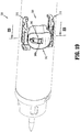
FIG. 23 is a cross-sectional end view taken along section line 23-23 shown inFIG. 19 , with the locking mechanism in a locked position; and -
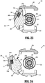
FIG. 24 is a cross-sectional end view taken along section line 23-23 shown inFIG. 19 , with the locking mechanism in an unlocked position. - Embodiments of the presently disclosed adapter assembly including a removable trocar assembly will now be described in detail with reference to the drawings in which like reference numerals designate identical or corresponding elements in each of the several views. As is common in the art, the term "proximal" refers to that part or component closer to the user or operator, i.e. surgeon or clinician, while the term "distal" refers to that part or component further away from the user.
- Referring initially to
FIG. 1 , an adapter assembly according to an embodiment of the present disclosure, shown generally asadapter assembly 100, is a component of an electromechanicalsurgical stapling device 10. Thesurgical stapling device 10 further includes apowered handle assembly 20, aloading unit 30, and ananvil assembly 40. Although shown and described with reference to the electromechanicalsurgical stapling device 10, the aspects of the present disclosure may be modified for use with manual surgical stapling devices having various configurations, and with powered surgical stapling devices having alternative configurations. For a detailed description of an exemplary powered handle assembly, please refer to commonly ownedU.S. Pat. Nos. 9,023,014 - With continued reference to
FIG. 1 , theadapter assembly 100 includes aproximal portion 102 configured for operable connection to thehandle assembly 20, and adistal portion 104 configured for operable connection to theloading unit 30 and for releasable attachment of atrocar assembly 120 to which theanvil assembly 40 is secured. Although shown and described as forming an integral unit, it is envisioned that the proximal anddistal portions - The
adapter assembly 100 will only be described to the extent necessary to fully disclose the aspects of the present disclosure. For a detailed description of an exemplary adapter assembly, please refer to commonly ownedU.S. Pat. Appl. Ser. No. 14/875,766 - With additional reference to
FIG. 2 , theadapter assembly 100 includes an outer sleeve 106 (FIG. 1 ), and aconnector housing 108 secured within a distal end of theouter sleeve 106. Theconnector housing 108 is configured to releasably secure an end effector, e.g., the loading unit 30 (FIG. 1 ), to theadapter assembly 100. - With continued reference to
FIG. 2 , theadapter assembly 100 includes adrive assembly 110 that extends through the outer sleeve 106 (FIG. 1 ) and that includes an innerflexible band assembly 112 and an outerflexible band assembly 114. The innerflexible band assembly 112 includes first and second innerflexible bands inner pusher member 112c connected to the distal ends of the first and second innerflexible bands flexible band assembly 114 includes first and second outerflexible bands outer pusher member 114c connected to the distal ends of the first and second outerflexible bands flexible bands flexible band assemblies upper band guide 116, and the second inner and outerflexible bands flexible band assemblies lower band guide 118. For a detailed description of the structure and function of an exemplary drive assembly, please refer to the '766 application, the content of which was previously incorporated herein by reference in its entirety. - With additional reference to
FIG. 3 , theadapter assembly 100 is configured to receive thetrocar assembly 120 within the connector housing 108 (FIG. 2 ) thereof, and includes a locking mechanism 130 (FIG. 2 ) for releasably securing thetrocar assembly 120 relative to and within theconnector housing 108 of theadapter assembly 100. - With reference now to
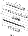
FIG. 4 , thetrocar assembly 120 of the adapter assembly 100 (FIG. 2 ) includes anouter housing 122 defining a lumen 122a therein, atrocar member 124 slidably disposed within the lumen 122a of theouter housing 122, and adrive screw 126 operably received within thetrocar member 124 for axially moving thetrocar member 124 relative to theouter housing 122. More specifically, aproximal end 124a of thetrocar member 124 defines a threadedbore 125 which is dimensioned to receive thedrive screw 126. The outer-surface of thedrive screw 126 is threaded such that rotation of thedrive screw 126 causes longitudinal movement of thetrocar member 124 within theouter housing 122 of thetrocar assembly 120. Thetrocar member 124 is keyed within theouter housing 122 such that thetrocar member 124 does not rotate relative to theouter housing 122 when thedrive screw 126 is rotated. For example, as shown inFIG. 4 , thetrocar member 124 includes a flattenedsurface 124c for engaging a surface (not shown) of theouter housing 122 to rotationally fixe thetrocar member 124 relative to theouter housing 122. Adistal end 124b oftrocar member 124 is configured to releasably engage an anvil assembly, e.g., the anvil assembly 40 (FIG. 1 ). - Proximal and
distal bearing assemblies outer housing 122 oftrocar assembly 120 for rotatably supporting thedrive screw 126 within theouter housing 122 and thetrocar member 124. As will be described in further detail below, theouter housing 122 defines first andsecond apertures FIG. 8 ) for receiving the respective first and second locking ends 148, 150 (FIG. 7 ) of the retainingmember 140 of thelocking mechanism 130 of theadapter assembly 100. - With reference now to
FIGS. 5-11 , thelocking mechanism 130 of theadapter assembly 100 includes a housing 132 (FIG. 8 ) through which thetrocar assembly 120 is received, and aretainer member 140 for securing thetrocar assembly 120 relative to thehousing 132. As seen inFIG. 8 , thehousing 132 of thelocking mechanism 130 is received between the first and second band guides 116, 118. As will be described in further detail below, theretainer member 140 is movable between a locked position (FIGS. 7 and 8 ) in which theretainer member 140 engages thetrocar assembly 120 to secure thetrocar assembly 120 relative to thehousing 132, and a unlocked position (FIGS. 10 and 11 ) in which theretainer member 140 is disengaged from thetrocar assembly 120 such that thetrocar assembly 120 may be removed from within thehousing 132 of thelocking mechanism 130. - With particular reference to
FIG. 8 , thehousing 132 of thelocking mechanism 130 is supported within theouter sleeve 106 of theadapter assembly 100 and defines athroughbore 131 through which thetrocar assembly 120 is received. Thehousing 132 further defines first andsecond openings throughbore 131. As will be described in further detail below, the first andsecond openings housing 132 are configured to align with the first andsecond apertures outer housing 122 of thetrocar assembly 120 when thetrocar assembly 120 is received within thethroughbore 131 of thehousing 132. - With additional reference to
FIG. 9 , theretainer member 140 of thelocking mechanism 130 includes a wire form curvedbody portion 142, curved first andsecond leg portions curved body portion 142, and first and second locking posts 148, 150 extending inwardly from the respective first andsecond leg portions retainer member 140 is secured to thehousing 132, thecurved body portion 142 of theretainer member 140 is received through a pair of slots 107 (FIG. 3 , only one visible) in theouter sleeve 106 of theadapter assembly 100 and is configured to be selectively received about thedrive assembly 110 and thetrocar assembly 120 to secure thetrocar assembly 120 relative tohousing 132 of thelocking mechanism 130. - In operation, the
ends FIG. 9 ) of thecurved body portion 142 of theretainer member 140 and/or the first andsecond leg portions retainer member 140 flex outwardly as theretainer member 140 is moved from the unlocked position (FIG. 10 ) to the locked position (FIG. 7 ). Additionally, when theretainer member 140 is in the locked position, theends curved body portion 142 and/or the first andsecond leg portions housing 132 of thelocking mechanism 130 to secure theretainer member 140 in the locked position. - With continued reference to
FIG. 9 , when theretainer member 140 is in a first or initial condition, the first and second locking posts 148, 150 thereof are separated by a first distance "d1". When theretainer member 140 is moved to a second or flexed condition, as indicated by arrows "A", the first and second locking posts 148, 150 are separated by a second distance "d2". As will be described in further detail below, the retainer remember 140 is in the first condition when thelocking mechanism 130 is in the locked position (FIG. 7 ) and theretainer member 140 is in the second condition when thelocking mechanism 130 is in the unlocked position (FIG. 10 ). - Each of the first and second locking posts 148, 150 of the
retainer member 140 may include atapered surface tapered surfaces retainer member 140 to its second condition during receipt of thetrocar assembly 120 within thethroughbore 131 of thehousing 132 of thelocking mechanism 130. In this manner, thetrocar assembly 120 may be received within thethroughbore 131 of thehousing 132 even when thelocking mechanism 130 is in the locked position. - To effect movement of the
retainer member 140 of thelocking mechanism 130 from the first condition to the second condition, thehousing 132 of thelocking mechanism 130 includes a pair of ramps 134 (FIG. 6 , shown in phantom, only one visible). The pair oframps 134 extend outwardly from thehousing 132 and are disposed adjacent the first andsecond openings housing 132. The pair oframps 134 are configured such that as theretainer member 140 is moved or pivoted from the locked position (FIG. 7 ) to the unlocked position (FIG. 10 ), the curved first andsecond leg portions retainer member 140 are flexed outwardly. - The pair of
ramps 134 may also assist in maintaining theretainer member 140 in the locked position. In particular, when theretainer member 140 is in the locked position, engagement of the first andsecond leg portions retainer member 140 with the pair oframps 134 frictionally prevents theretainer member 140 from pivoting to the open position without additional assistance from a clinician. - The operation of the
locking mechanism 130 will now be described with reference toFIGS. 1-11 , and specificallyFIGS. 7-11 . Theadapter assembly 100 may be provided to the clinician with thetrocar assembly 120 secured therein, or thetrocar assembly 120 may be provided separate from theadapter assembly 100. If thetrocar assembly 130 is provided to the clinician separately, prior to use, thetrocar assembly 120 must be secured to theadapter assembly 100, wherein a proximal end of thetrocar assembly 120 is inserted into and received through thethroughbore 131 of thehousing 132 of thelocking mechanism 130. As noted above, taperedsurfaces trocar assembly 120 through thehousing 132 when theretainer member 140 of thelocking mechanism 130 is in the locked position. More particularly, when theretainer member 140 is in the locked position, engagement of the taperedsurfaces trocar assembly 120 causes the first and second locking posts 148, 150 to flex outwardly to permit thetrocar assembly 120 to be passed through thehousing 132. When thetrocar assembly 120 is fully seated within theadapter assembly 100, theretainer member 140 springs back to its initial condition (FIG. 8 ) to secure thetrocar assembly 120 within theadapter assembly 100. When thetrocar assembly 120 is fully seated within theadapter assembly 100, first and second locking posts 148, 150 engage and enter the respective first andsecond apertures housing 122 of thetrocar assembly 120. (seeFIG. 8 ). - Alternatively, prior to insertion of the
trocar assembly 120 through thethroughbore 131 of thehousing 132 of thelocking mechanism 130, theretainer member 140 may be moved to the unlocked position to permit unobstructed receipt of thetrocar assembly 120 through thehousing 132. Once thetrocar assembly 120 is fully seated with theadapter assembly 100, the clinician may move theretainer member 140 to the locked position to allow theretainer member 140 to return to the initial condition such that the first and second locking posts 148, 150 engage and enter the first andsecond apertures housing 122 of thetrocar assembly 120. - Subsequent to the
trocar assembly 120 being secured within theadapter assembly 100, theadapter assembly 100 may be operated in a traditional manner. - With particular reference now to
FIGS. 10 and 11 , as discussed above, removal of thetrocar assembly 120 from theadapter assembly 100 requires movement of theretainer member 140 of thelocking mechanism 130 from the locked positon (FIG. 8 ) to the unlocked position, as indicated by arrow "B" inFIG. 10 . As theretainer member 140 is moved from the locked position to the unlocked position, the curved first andsecond leg portions ramps 134 on thehousing 132 of thelocking mechanism 130 to move the respective first and second locking posts 148, 150 outwardly to the flexed condition. When theretainer member 140 is in the flexed position, the first and second locking posts 148, 150 of theretainer member 140 are completely withdrawn from within the first andsecond apertures housing 122 of thetrocar assembly 120. In this manner, thetrocar assembly 120 is no longer secured within theadapter assembly 100, and may be removed therefrom. - With reference now to
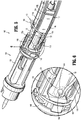
FIGS. 12-16 , an adapter assembly according to another embodiment of the present disclosure is shown generally asadapter assembly 200. Theadapter assembly 200 is substantially similar toadapter assembly 100 described hereinabove, and will only be described further hereinbelow as relates to the differences therebetween. - The
adapter assembly 200 includes aconnector housing 208, adrive assembly 210 extending through theconnector housing 208, and alocking mechanism 230 for releasably securing atrocar assembly 220 within theconnector housing 208. Thedrive assembly 210 includes an innerflexible band assembly 212 and an outerflexible band assembly 214. The inner and outerflexible band assemblies - With continued reference to
FIGS. 12-16 , thelocking mechanism 230 of theadapter assembly 200 includes aretainer member 240 for selective engagement with ahousing 222 of thetrocar assembly 220. The retainingmember 240 is in the form of a flexible clip having abase portion 242, first andsecond leg portions base portion 242, and first and secondcurved engagement portions second leg portions second leg portions FIG. 15 ) of thedrive assembly 210 of theadapter assembly 200. Theengagement portions retainer member 240 curve radially inward towards one another and are configured to be selectively received within first andsecond retention slots housing 222 of thetrocar assembly 220. The first andsecond leg portions retainer member 240 are configured to flex outwardly to cause therespective engagement portions - The
retainer member 240 further includes atab second leg portions tabs upper band guide 216 of thedrive assembly 210 when theretainer member 240 is received over theupper band guide 216 to maintain theretainer member 240 about theupper band guide 216. - With particular reference now to
FIG. 15 , thelocking mechanism 230 is shown with the retainingmember 240 in a locked position. In the locked position, thebase portion 242 and the first andsecond leg portions retainer member 240 are received about theupper band guide 216 of thedrive assembly 210, and the first andsecond engagement portions retainer member 240 engage thelower band guide 218 of thedrive assembly 210. Engagement of the first andsecond engagement portions lower band guide 218 biases theretainer member 240 radially outward. In this manner, thebase portion 242 of theretainer member 240 is radially spaced from theupper band guide 216. As noted above, thetabs retainer member 240 engage theupper band guide 216 to maintain theretainer member 240 about theupper band guide 216. - When the
trocar assembly 220 is fully received within theadapter assembly 200, and theretainer member 240 is in the locked position, theengagement portions retainer member 240 are received within the first andsecond retention slots trocar assembly 220. Theengagement portions retainer member 240 secure thetrocar member 240 within theadapter assembly 200. - With particular reference now to
FIG. 16 , thelocking mechanism 230 is shown with theretainer member 240 in a second position. When thelocking mechanism 230 is in the second position, theretainer member 240 is in a second or flexed condition. To move theretainer member 240 to the flexed condition, a clinician (not shown) depresses thebase portion 242 of theretainer member 240, as indicated by arrow "C", to cause radially inward movement of thebase portion 242 of theretainer member 240 with respect to theupper band guide 216. - As the
retainer member 240 is moved radially inwardly, the first andsecond engagement portions retainer member 240 engage thelower band guide 218, causing the first andsecond leg portions second engagement portions FIG. 16 . Movement of the first andsecond engagement portions second engagement portions second retention slots housing 220 of thetrocar assembly 220, thereby disengaging theretainer member 240 from thetrocar assembly 220. Once theretainer member 240 is in the unlocked position, i.e., disengaged from thetrocar assembly 220, thetrocar assembly 220 may be removed from theadapter assembly 200. - Release of the
retainer member 240 permits theretainer member 240 to return to the locked position (FIG. 15 ) due to the spring bias of the first andsecond engagement portions second engagement portions second retention slots trocar assembly 220, and thus move thebase portion 242 radially outward. Loading of thetrocar assembly 220 within theadapter assembly 200 may require theretainer member 240 to be moved to the unlocked position to permit thetrocar assembly 220 to be received through thelocking mechanism 230. - With reference to
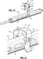
FIGS. 17 and 18 , alternative embodiments of a retainer member are shown generally asretainer members 240a (FIG. 17 ), 240b (FIG. 18 ). Theretainer member 240a includes a pair of flanges 248a (only one shown) extending inwardly from respective first andsecond leg portions flanges 248a, 250a are selectively receivable within first andsecond retention slots FIG. 16 ) of a trocar assembly 220 (for example, seeFIG. 16 ) for releasably securing the trocar assembly within an adapter assembly 200 (for example, seeFIG. 16 ). Similarly, theretainer member 240b includes a pair ofcurved engagement portions second leg portions curved engagement portions second retention slots trocar assembly 220. - With reference now to
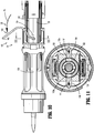
FIGS. 19-24 , an adapter assembly according to another embodiment of the present disclosure is shown generally as adapter assembly 300 (shown in phantom). Theadapter assembly 300 is substantially similar toadapter assemblies - The
adapter assembly 300 includes a locking mechanism 330that operates to maintain atrocar assembly 320 within the adapter assembly 300 (FIG. 19 ). Thelocking mechanism 330 includes aretainer member 340 pivotally secured to a lower band guide 318 (FIGS. 23 and 24 ) of a drive assembly (not shown) of the adapter assembly 300 (FIG. 19 ), and alatch member 346 operably received within acutout 341 of theretainer member 340. Theretainer member 340 includes aprotrusion 342 configured to be received within afirst retention slot 323a of ahousing 322 of thetrocar assembly 320 when thelocking mechanism 330 is in a locked position (FIG. 23 ). Thelatch member 346 includes anengagement portion 346a configured for operable engagement by a user, and alatch portion 346b configured to engage anupper band guide 316 of the drive assembly (not shown) of theadapter assembly 300. A biasing member, e.g., compression spring 338, biases the latch member 336 to a first position (FIG. 23 ). - With particular reference to
FIG. 24 , thelocking mechanism 330 is shown in the locked position. When thelocking mechanism 330 is in the locked position, theprotrusion 342 of theretainer member 340 is received within thefirst retention slot 323a of thehousing 322 of thetrocar assembly 320 and the lock portion 336b of the latch member 336 is engaged with the upper band guide 316 (FIGS. 23 and 24 ). Although shown only including asingle retainer member 340, it is envisioned that thelocking mechanism 340 may include a second retainer member (not shown) pivotally secured to thelower band guide 318 and including a protrusion (not shown) receivable within thesecond retention slot 323a of thehousing 322 of thetrocar assembly 320. - Turning now to FIG. 25, the
locking mechanism 330 is shown in the unlocked position. To move thelocking mechanism 330 to the unlocked position, the clinician presses downward against theengagement portion 346a of thelatch member 346, as indicated by arrow "D", to move thelock portion 346b of thelatch member 346 out of engagement withupper band guide 316. Once thelock portion 346b of thelatch member 346 is disengaged from theupper band guide 316, theretainer member 340 may be pivoted to the unlocked position, as indicated by arrow "E", to remove theprotrusion 342 of theretainer member 340 from within thefirst retention slot 323a of thetrocar assembly 320. Thetrocar assembly 320 may then be removed from theadapter assembly 300. - Although the illustrative embodiments of the present disclosure have been described herein with reference to the accompanying drawings, it is to be understood that the disclosure is not limited to those precise embodiments, and that various other changes and modifications may be effected therein by one skilled in the art without departing from the scope or spirit of the disclosure. For example, in any of the embodiments discussed herein, the trocar assembly may form part of a circular surgical stapler that is wholly or partially disposable and such instruments may have a separate adapter or the adapter may be formed as part of the handle assembly. The stapling instrument can be manually operated, powered through an integral or separate motor, or form part of a robotic system.
- The invention may be described by reference to the following numbered paragraphs:-
- 1. An adapter assembly for connecting a surgical loading unit to a handle assembly, the adapter assembly comprising:
- a sleeve;
- a trocar assembly releasably securable within the sleeve, the trocar assembly including a trocar housing defining first and second locking slots; and
- a locking mechanism configured to releasably secure the trocar assembly within the sleeve, the locking mechanism including a retaining member having first and second engagement portions configured for selective reception within the first and second locking slots, respectively, of the trocar housing.
- 2. The adapter assembly of paragraph 1, wherein the retainer member is a formed wire and the first and second engagement portions include first and second locking posts moveable between a first position engaged with the trocar assembly such that the trocar assembly is securely received within the sleeve, and a second position disengaged from the trocar assembly such that the trocar assembly is removable from within the sleeve.
- 3. The adapter assembly of paragraph 2, wherein the retainer member is configured to be pivoted between the first position and the second position.
- 4. The adapter assembly of paragraph 3, wherein the locking mechanism further includes a lock housing, and first and second ramp members extending from the lock housing, the first and second ramp members being configured to urge the first and second locking posts from an initial position in engagement with the trocar housing to a spaced apart position disengaged from the trocar housing as the retainer member is moved from the first position to the second position.
- 5. The adapter assembly of paragraph 1, wherein the retainer member includes a base portion, and first and second leg portions extending from the base portion, the first and second engagement portions extend from the respective first and second leg portions.
- 6. The adapter assembly of paragraph 5, further including upper and lower band guides, wherein the retainer member is slidably received over the upper band guide and engages the lower band guide.
- 7. The adapter assembly of
paragraph 6, wherein engagement of the retainer member with the lower band guide biases the retainer member radially outwardly. - 8. The adapter assembly of
paragraph 6, wherein the retainer member is moveable relative to the upper and lower band guides from a first position in engagement with the trocar housing, to a second position disengaged from the trocar housing. - 9. The adapter assembly of
paragraph 6, wherein the base portion of the retainer member is configured to be moved radially inward relative to the sleeve. - 10. The adapter assembly of
paragraph 6, wherein the retainer member further includes first and second posts for maintaining the retainer member about the upper band guide. - 11. The adapter assembly of
paragraph 6, wherein the first and second engagement portions include first and second tabs for engaging the trocar housing of the trocar assembly. - 12. The adapter assembly of
paragraph 6, wherein the first and second engagement portions are curved towards one another and are configured to engage the trocar housing of the trocar assembly. - 13. An adapter assembly for connecting a loading unit to a handle assembly, the adapter assembly comprising:
- a sleeve;
- upper and lower band guides disposed within the sleeve;
- a trocar assembly releasably securable within the sleeve, the trocar assembly including a trocar housing defining at least a first retention slot; and
- a locking mechanism configured to releasably secure the trocar assembly within the sleeve, the locking mechanism including a retaining member pivotally secured to the lower band guide and including a protrusion configured for selective reception within the at least first retention slot of the trocar housing.
- 14. The adapter assembly of paragraph 13, wherein the retainer member is movable between a first position engaged with the trocar housing and a second position disengaged from the trocar housing.
- 15. The adapter assembly of paragraph 14, wherein the locking mechanism includes a latch member having an engagement portion for facilitating movement of the latch member by a user.
- 16. The adapter assembly of
paragraph 15, wherein the locking mechanism further includes a spring for biasing the latch member to a locked position. - 17. The adapter assembly of
paragraph 15, wherein the latch member includes a locking portion for engaging the upper band guide when the retainer member is in the first position.
Claims (15)
- An adapter assembly for connecting a surgical loading unit to a handle assembly, the adapter assembly comprising:a sleeve;a trocar assembly releasably securable within the sleeve, the trocar assembly including a trocar housing defining first and second locking slots; anda locking mechanism configured to releasably secure the trocar assembly within the sleeve, the locking mechanism including a retaining member having first and second engagement portions configured for selective reception within the first and second locking slots, respectively, of the trocar housing.
- The adapter assembly of claim 1, wherein the retainer member is a formed wire and the first and second engagement portions include first and second locking posts moveable between a first position engaged with the trocar assembly such that the trocar assembly is securely received within the sleeve, and a second position disengaged from the trocar assembly such that the trocar assembly is removable from within the sleeve.
- The adapter assembly of claim 2, wherein the retainer member is configured to be pivoted between the first position and the second position.
- The adapter assembly of claim 3, wherein the locking mechanism further includes a lock housing, and first and second ramp members extending from the lock housing, the first and second ramp members being configured to urge the first and second locking posts from an initial position in engagement with the trocar housing to a spaced apart position disengaged from the trocar housing as the retainer member is moved from the first position to the second position.
- The adapter assembly of any preceding claim wherein the retainer member includes a base portion, and first and second leg portions extending from the base portion, the first and second engagement portions extend from the respective first and second leg portions.
- The adapter assembly of claim 5, further including upper and lower band guides, wherein the retainer member is slidably received over the upper band guide and engages the lower band guide.
- The adapter assembly of claim 6, wherein engagement of the retainer member with the lower band guide biases the retainer member radially outwardly.
- The adapter assembly of claim 6, wherein the retainer member is moveable relative to the upper and lower band guides from a first position in engagement with the trocar housing, to a second position disengaged from the trocar housing.
- The adapter assembly of claim 6, wherein the base portion of the retainer member is configured to be moved radially inward relative to the sleeve.
- The adapter assembly of claim 6, wherein the retainer member further includes first and second posts for maintaining the retainer member about the upper band guide.
- The adapter assembly of claim 6, wherein the first and second engagement portions include first and second tabs for engaging the trocar housing of the trocar assembly; and/or wherein the first and second engagement portions are curved towards one another and are configured to engage the trocar housing of the trocar assembly.
- An adapter assembly for connecting a loading unit to a handle assembly, the adapter assembly comprising:a sleeve;upper and lower band guides disposed within the sleeve;a trocar assembly releasably securable within the sleeve, the trocar assembly including a trocar housing defining at least a first retention slot; anda locking mechanism configured to releasably secure the trocar assembly within the sleeve, the locking mechanism including a retaining member pivotally secured to the lower band guide and including a protrusion configured for selective reception within the at least first retention slot of the trocar housing.
- The adapter assembly of claim 12, wherein the retainer member is movable between a first position engaged with the trocar housing and a second position disengaged from the trocar housing.
- The adapter assembly of claim 12 or claim 13, wherein the locking mechanism includes a latch member having an engagement portion for facilitating movement of the latch member by a user.
- The adapter assembly of claim 14, wherein the locking mechanism further includes a spring for biasing the latch member to a locked position; and/or wherein the latch member includes a locking portion for engaging the upper band guide when the retainer member is in the first position.
Applications Claiming Priority (1)
| Application Number | Priority Date | Filing Date | Title |
|---|---|---|---|
| US15/157,136 US10702302B2 (en) | 2016-05-17 | 2016-05-17 | Adapter assembly including a removable trocar assembly |
Publications (3)
| Publication Number | Publication Date |
|---|---|
| EP3245959A2 true EP3245959A2 (en) | 2017-11-22 |
| EP3245959A3 EP3245959A3 (en) | 2018-03-21 |
| EP3245959B1 EP3245959B1 (en) | 2022-11-16 |
Family
ID=58709883
Family Applications (1)
| Application Number | Title | Priority Date | Filing Date |
|---|---|---|---|
| EP17171265.6A Active EP3245959B1 (en) | 2016-05-17 | 2017-05-16 | Adapter assembly including a removable trocar assembly |
Country Status (7)
| Country | Link |
|---|---|
| US (1) | US10702302B2 (en) |
| EP (1) | EP3245959B1 (en) |
| JP (1) | JP6982981B2 (en) |
| CN (1) | CN107374686B (en) |
| AU (1) | AU2017203266B2 (en) |
| CA (1) | CA2967526A1 (en) |
| ES (1) | ES2931463T3 (en) |
Cited By (9)
| Publication number | Priority date | Publication date | Assignee | Title |
|---|---|---|---|---|
| EP3666198A3 (en) * | 2018-12-13 | 2020-09-30 | Covidien LP | Lockout mechanisms for surgical instruments |
| EP3730072A1 (en) * | 2019-04-22 | 2020-10-28 | Covidien LP | Electromechanical surgical stapler including trocar assembly release mechanism |
| EP3782560A1 (en) * | 2019-06-24 | 2021-02-24 | Covidien LP | Retaining mechanisms for trocar assembly |
| EP3760137A3 (en) * | 2019-07-05 | 2021-03-10 | Covidien LP | Trocar coupling assemblies for a surgical stapler |
| EP3845150A1 (en) * | 2020-01-06 | 2021-07-07 | Covidien LP | Assemblies for retaining a trocar assembly |
| EP3884879A1 (en) * | 2020-03-24 | 2021-09-29 | Covidien LP | Retaining mechanisms for trocar assemblies |
| US11426170B2 (en) | 2020-03-24 | 2022-08-30 | Covidien Lp | Retaining mechanisms for trocar assemblies |
| US11426169B2 (en) | 2020-03-24 | 2022-08-30 | Covidien Lp | Retaining mechanisms for trocar assemblies |
| US11969298B2 (en) | 2022-07-12 | 2024-04-30 | Covidien Lp | Lockout mechanisms for surgical instruments |
Families Citing this family (12)
| Publication number | Priority date | Publication date | Assignee | Title |
|---|---|---|---|---|
| US11534172B2 (en) | 2018-05-07 | 2022-12-27 | Covidien Lp | Electromechanical surgical stapler including trocar assembly release mechanism |
| US11399839B2 (en) | 2018-05-07 | 2022-08-02 | Covidien Lp | Surgical devices including trocar lock and trocar connection indicator |
| JP2021534841A (en) | 2018-08-31 | 2021-12-16 | プロ−デツクス・インコーポレイテツド | Surgical tool mounting equipment, systems, and methods |
| US10973544B2 (en) * | 2018-10-02 | 2021-04-13 | Covidien Lp | Retaining mechanism for trocar assembly |
| US11051819B2 (en) * | 2018-10-15 | 2021-07-06 | Cilag Gmbh International | Latch to prevent back-driving of circular surgical stapler |
| US11337701B2 (en) * | 2019-03-01 | 2022-05-24 | Covidien Lp | Devices and methods for assembling adapter assemblies |
| US11317945B2 (en) * | 2019-04-16 | 2022-05-03 | Covidien Lp | Trocar assemblies for adapter assemblies for surgical stapling instruments |
| CN111820981A (en) * | 2019-04-22 | 2020-10-27 | 柯惠Lp公司 | Surgical device including trocar lock and trocar connection indicator |
| US11123101B2 (en) * | 2019-07-05 | 2021-09-21 | Covidien Lp | Retaining mechanisms for trocar assemblies |
| US11446035B2 (en) * | 2019-06-24 | 2022-09-20 | Covidien Lp | Retaining mechanisms for trocar assemblies |
| US20210137590A1 (en) * | 2019-11-11 | 2021-05-13 | Jeffrey MacDonald | Electrical connector for colpotomy device |
| US11517317B2 (en) * | 2020-01-06 | 2022-12-06 | Covidien Lp | Trocar release assemblies for a surgical stapler |
Citations (2)
| Publication number | Priority date | Publication date | Assignee | Title |
|---|---|---|---|---|
| US9023014B2 (en) | 2007-09-21 | 2015-05-05 | Covidien Lp | Quick connect assembly for use between surgical handle assembly and surgical accessories |
| US9055943B2 (en) | 2007-09-21 | 2015-06-16 | Covidien Lp | Hand held surgical handle assembly, surgical adapters for use between surgical handle assembly and surgical end effectors, and methods of use |
Family Cites Families (362)
| Publication number | Priority date | Publication date | Assignee | Title |
|---|---|---|---|---|
| US2777340A (en) | 1955-09-28 | 1957-01-15 | Leonard J Hettwer | Offset drilling attachment |
| US2957353A (en) | 1958-08-26 | 1960-10-25 | Teleflex Inc | Connector |
| US3111328A (en) | 1961-07-03 | 1963-11-19 | Rito Vincent L J Di | Multiuse adapter for manipulators |
| US3734515A (en) | 1971-01-29 | 1973-05-22 | Thor Power Tool Co | Power wrench with interchangeable adapters |
| US3695058A (en) | 1971-05-26 | 1972-10-03 | Marvin W Keith Jr | Flexible link rotatable drive coupling |
| US3759336A (en) | 1972-01-21 | 1973-09-18 | D Marcovitz | Interchangeable power operated tools |
| US4162399A (en) | 1977-09-16 | 1979-07-24 | Bei Electronics, Inc. | Optical encoder with fiber optics |
| US4606343A (en) | 1980-08-18 | 1986-08-19 | United States Surgical Corporation | Self-powered surgical fastening instrument |
| US4705038A (en) | 1985-01-23 | 1987-11-10 | Dyonics, Inc. | Surgical system for powered instruments |
| US4722685A (en) | 1985-05-30 | 1988-02-02 | Estrada Juan M De | Tool for adapting a portable lathe to treat the back molar teeth of horses |
| US4823807A (en) | 1988-02-11 | 1989-04-25 | Board Of Regents, Univ. Of Texas System | Device for non-invasive diagnosis and monitoring of articular and periarticular pathology |
| US4874181A (en) | 1988-05-31 | 1989-10-17 | Hsu Shing Wang | Coupling member for securing a drilling head to the rotatable rod of a pneumatic tool body |
| US5301061A (en) | 1989-07-27 | 1994-04-05 | Olympus Optical Co., Ltd. | Endoscope system |
| US5152744A (en) | 1990-02-07 | 1992-10-06 | Smith & Nephew Dyonics | Surgical instrument |
| US5104025A (en) * | 1990-09-28 | 1992-04-14 | Ethicon, Inc. | Intraluminal anastomotic surgical stapler with detached anvil |
| JP3034019B2 (en) | 1990-11-26 | 2000-04-17 | 旭光学工業株式会社 | Endoscope tip |
| US5129570A (en) | 1990-11-30 | 1992-07-14 | Ethicon, Inc. | Surgical stapler |
| US5413267A (en) | 1991-05-14 | 1995-05-09 | United States Surgical Corporation | Surgical stapler with spent cartridge sensing and lockout means |
| US5129118A (en) | 1991-07-29 | 1992-07-14 | Walmesley Mark W | Accessory tool apparatus for use on power drills |
| US5312023A (en) | 1991-10-18 | 1994-05-17 | United States Surgical Corporation | Self contained gas powered surgical apparatus |
| US5326013A (en) | 1991-10-18 | 1994-07-05 | United States Surgical Corporation | Self contained gas powered surgical apparatus |
| US5478003A (en) | 1991-10-18 | 1995-12-26 | United States Surgical Corporation | Surgical apparatus |
| US5197649A (en) | 1991-10-29 | 1993-03-30 | The Trustees Of Columbia University In The City Of New York | Gastrointestinal endoscoptic stapler |
| US5383874A (en) | 1991-11-08 | 1995-01-24 | Ep Technologies, Inc. | Systems for identifying catheters and monitoring their use |
| US5433721A (en) | 1992-01-17 | 1995-07-18 | Ethicon, Inc. | Endoscopic instrument having a torsionally stiff drive shaft for applying fasteners to tissue |
| US5383880A (en) | 1992-01-17 | 1995-01-24 | Ethicon, Inc. | Endoscopic surgical system with sensing means |
| US5350355A (en) | 1992-02-14 | 1994-09-27 | Automated Medical Instruments, Inc. | Automated surgical instrument |
| US5389098A (en) | 1992-05-19 | 1995-02-14 | Olympus Optical Co., Ltd. | Surgical device for stapling and/or fastening body tissues |
| US5658300A (en) | 1992-06-04 | 1997-08-19 | Olympus Optical Co., Ltd. | Tissue fixing surgical instrument, tissue-fixing device, and method of fixing tissues |
| US5609560A (en) | 1992-08-19 | 1997-03-11 | Olympus Optical Co., Ltd. | Medical operation device control system for controlling a operation devices accessed respectively by ID codes |
| US5662662A (en) | 1992-10-09 | 1997-09-02 | Ethicon Endo-Surgery, Inc. | Surgical instrument and method |
| US5431323A (en) | 1992-10-09 | 1995-07-11 | Ethicon, Inc. | Endoscopic surgical instrument with pivotable and rotatable staple cartridge |
| US5626587A (en) | 1992-10-09 | 1997-05-06 | Ethicon Endo-Surgery, Inc. | Method for operating a surgical instrument |
| US5601224A (en) | 1992-10-09 | 1997-02-11 | Ethicon, Inc. | Surgical instrument |
| US5400267A (en) | 1992-12-08 | 1995-03-21 | Hemostatix Corporation | Local in-device memory feature for electrically powered medical equipment |
| US5540706A (en) | 1993-01-25 | 1996-07-30 | Aust; Gilbert M. | Surgical instrument |
| US5540375A (en) | 1993-04-20 | 1996-07-30 | United States Surgical Corporation | Endoscopic stapler |
| US5467911A (en) | 1993-04-27 | 1995-11-21 | Olympus Optical Co., Ltd. | Surgical device for stapling and fastening body tissues |
| CA2124109A1 (en) | 1993-05-24 | 1994-11-25 | Mark T. Byrne | Endoscopic surgical instrument with electromagnetic sensor |
| US5542594A (en) | 1993-10-06 | 1996-08-06 | United States Surgical Corporation | Surgical stapling apparatus with biocompatible surgical fabric |
| US5487499A (en) | 1993-10-08 | 1996-01-30 | United States Surgical Corporation | Surgical apparatus for applying surgical fasteners including a counter |
| US5476379A (en) | 1993-11-04 | 1995-12-19 | Disel; Jimmy D. | Illumination system and connector assembly for a dental handpiece |
| US5782397A (en) | 1994-01-04 | 1998-07-21 | Alpha Surgical Technologies, Inc. | Stapling device |
| US6165169A (en) | 1994-03-04 | 2000-12-26 | Ep Technologies, Inc. | Systems and methods for identifying the physical, mechanical, and functional attributes of multiple electrode arrays |
| US5526822A (en) | 1994-03-24 | 1996-06-18 | Biopsys Medical, Inc. | Method and apparatus for automated biopsy and collection of soft tissue |
| US5529235A (en) | 1994-04-28 | 1996-06-25 | Ethicon Endo-Surgery, Inc. | Identification device for surgical instrument |
| US5553675A (en) | 1994-06-10 | 1996-09-10 | Minnesota Mining And Manufacturing Company | Orthopedic surgical device |
| EP0699418A1 (en) | 1994-08-05 | 1996-03-06 | United States Surgical Corporation | Self-contained powered surgical apparatus |
| US5779130A (en) | 1994-08-05 | 1998-07-14 | United States Surgical Corporation | Self-contained powered surgical apparatus |
| EP0705571A1 (en) | 1994-10-07 | 1996-04-10 | United States Surgical Corporation | Self-contained powered surgical apparatus |
| US5549637A (en) | 1994-11-10 | 1996-08-27 | Crainich; Lawrence | Articulated medical instrument |
| US5868760A (en) | 1994-12-07 | 1999-02-09 | Mcguckin, Jr.; James F. | Method and apparatus for endolumenally resectioning tissue |
| US5713505A (en) | 1996-05-13 | 1998-02-03 | Ethicon Endo-Surgery, Inc. | Articulation transmission mechanism for surgical instruments |
| US5632432A (en) | 1994-12-19 | 1997-05-27 | Ethicon Endo-Surgery, Inc. | Surgical instrument |
| US5704534A (en) | 1994-12-19 | 1998-01-06 | Ethicon Endo-Surgery, Inc. | Articulation assembly for surgical instruments |
| US6321855B1 (en) | 1994-12-29 | 2001-11-27 | George Edward Barnes | Anti-vibration adaptor |
| US5649956A (en) | 1995-06-07 | 1997-07-22 | Sri International | System and method for releasably holding a surgical instrument |
| US5762256A (en) | 1995-08-28 | 1998-06-09 | United States Surgical Corporation | Surgical stapler |
| US5782396A (en) | 1995-08-28 | 1998-07-21 | United States Surgical Corporation | Surgical stapler |
| US6032849A (en) | 1995-08-28 | 2000-03-07 | United States Surgical | Surgical stapler |
| BR9607702A (en) | 1995-09-15 | 1998-01-13 | Robert Lee Thompson | Surgical device / diagnostic imaging |
| US7141049B2 (en) | 1999-03-09 | 2006-11-28 | Thermage, Inc. | Handpiece for treatment of tissue |
| US6010054A (en) | 1996-02-20 | 2000-01-04 | Imagyn Medical Technologies | Linear stapling instrument with improved staple cartridge |
| US6699177B1 (en) | 1996-02-20 | 2004-03-02 | Computer Motion, Inc. | Method and apparatus for performing minimally invasive surgical procedures |
| US5820009A (en) | 1996-02-20 | 1998-10-13 | Richard-Allan Medical Industries, Inc. | Articulated surgical instrument with improved jaw closure mechanism |
| US6119913A (en) | 1996-06-14 | 2000-09-19 | Boston Scientific Corporation | Endoscopic stapler |
| US5855312A (en) * | 1996-07-25 | 1999-01-05 | Toledano; Haviv | Flexible annular stapler for closed surgery of hollow organs |
| US6017354A (en) | 1996-08-15 | 2000-01-25 | Stryker Corporation | Integrated system for powered surgical tools |
| US6129547A (en) | 1997-05-06 | 2000-10-10 | Ballard Medical Products | Oral care system |
| US6126651A (en) | 1997-08-11 | 2000-10-03 | Mayer; Paul W. | Motorized motion-canceling suture tool holder |
| US6434507B1 (en) | 1997-09-05 | 2002-08-13 | Surgical Navigation Technologies, Inc. | Medical instrument and method for use with computer-assisted image guided surgery |
| US5865361A (en) | 1997-09-23 | 1999-02-02 | United States Surgical Corporation | Surgical stapling apparatus |
| US5863159A (en) | 1997-12-12 | 1999-01-26 | Lasko; Leonard J. | Drill angle attachment coupling |
| DE69922791T2 (en) | 1998-02-19 | 2005-12-08 | California Institute Of Technology, Pasadena | DEVICE FOR PROVIDING A SPHERICAL SEA FIELD DURING ENDOSCOPIC INTERVENTION |
| US6239732B1 (en) | 1998-04-13 | 2001-05-29 | Dallas Semiconductor Corporation | One-wire device with A-to-D converter |
| US6126058A (en) | 1998-06-19 | 2000-10-03 | Scimed Life Systems, Inc. | Method and device for full thickness resectioning of an organ |
| US6256859B1 (en) | 1998-09-25 | 2001-07-10 | Sherwood Services Ag | Method of manufacturing an aspiring tool |
| US5993454A (en) | 1998-09-29 | 1999-11-30 | Stryker Corporation | Drill attachment for a surgical drill |
| US7238021B1 (en) | 1998-12-03 | 2007-07-03 | Johnson Gary E | Powered cutting surface with protective guard for equine teeth |
| US6860892B1 (en) | 1999-05-28 | 2005-03-01 | General Surgical Innovations, Inc. | Specially shaped balloon device for use in surgery and method of use |
| US6716233B1 (en) | 1999-06-02 | 2004-04-06 | Power Medical Interventions, Inc. | Electromechanical driver and remote surgical instrument attachment having computer assisted control capabilities |
| US7951071B2 (en) | 1999-06-02 | 2011-05-31 | Tyco Healthcare Group Lp | Moisture-detecting shaft for use with an electro-mechanical surgical device |
| US8241322B2 (en) | 2005-07-27 | 2012-08-14 | Tyco Healthcare Group Lp | Surgical device |
| US6793652B1 (en) | 1999-06-02 | 2004-09-21 | Power Medical Interventions, Inc. | Electro-mechanical surgical device |
| US7032798B2 (en) | 1999-06-02 | 2006-04-25 | Power Medical Interventions, Inc. | Electro-mechanical surgical device |
| US6264087B1 (en) | 1999-07-12 | 2001-07-24 | Powermed, Inc. | Expanding parallel jaw device for use with an electromechanical driver device |
| US6491201B1 (en) | 2000-02-22 | 2002-12-10 | Power Medical Interventions, Inc. | Fluid delivery mechanism for use with anastomosing, stapling, and resecting instruments |
| US6315184B1 (en) | 1999-06-02 | 2001-11-13 | Powermed, Inc. | Stapling device for use with an electromechanical driver device for use with anastomosing, stapling, and resecting instruments |
| US6981941B2 (en) | 1999-06-02 | 2006-01-03 | Power Medical Interventions | Electro-mechanical surgical device |
| US6443973B1 (en) | 1999-06-02 | 2002-09-03 | Power Medical Interventions, Inc. | Electromechanical driver device for use with anastomosing, stapling, and resecting instruments |
| US8025199B2 (en) | 2004-02-23 | 2011-09-27 | Tyco Healthcare Group Lp | Surgical cutting and stapling device |
| US6451007B1 (en) | 1999-07-29 | 2002-09-17 | Dale E. Koop | Thermal quenching of tissue |
| US6611793B1 (en) | 1999-09-07 | 2003-08-26 | Scimed Life Systems, Inc. | Systems and methods to identify and disable re-use single use devices based on detecting environmental changes |
| US6368324B1 (en) | 1999-09-24 | 2002-04-09 | Medtronic Xomed, Inc. | Powered surgical handpiece assemblies and handpiece adapter assemblies |
| US8016855B2 (en) | 2002-01-08 | 2011-09-13 | Tyco Healthcare Group Lp | Surgical device |
| US7770773B2 (en) | 2005-07-27 | 2010-08-10 | Power Medical Interventions, Llc | Surgical device |
| US6533157B1 (en) | 2000-02-22 | 2003-03-18 | Power Medical Interventions, Inc. | Tissue stapling attachment for use with an electromechanical driver device |
| US6348061B1 (en) | 2000-02-22 | 2002-02-19 | Powermed, Inc. | Vessel and lumen expander attachment for use with an electromechanical driver device |
| US6488197B1 (en) | 2000-02-22 | 2002-12-03 | Power Medical Interventions, Inc. | Fluid delivery device for use with anastomosing resecting and stapling instruments |
| JP3897962B2 (en) | 2000-07-19 | 2007-03-28 | 株式会社モリタ製作所 | Identification-type instrument body, identification-type adapter, identification-type tube, and medical device using these |
| US6830174B2 (en) | 2000-08-30 | 2004-12-14 | Cerebral Vascular Applications, Inc. | Medical instrument |
| US6817508B1 (en) | 2000-10-13 | 2004-11-16 | Tyco Healthcare Group, Lp | Surgical stapling device |
| US6716226B2 (en) | 2001-06-25 | 2004-04-06 | Inscope Development, Llc | Surgical clip |
| US20050004559A1 (en) | 2003-06-03 | 2005-01-06 | Senorx, Inc. | Universal medical device control console |
| US8313496B2 (en) | 2001-02-02 | 2012-11-20 | Lsi Solutions, Inc. | System for endoscopic suturing |
| US7699835B2 (en) | 2001-02-15 | 2010-04-20 | Hansen Medical, Inc. | Robotically controlled surgical instruments |
| US7905897B2 (en) | 2001-03-14 | 2011-03-15 | Tyco Healthcare Group Lp | Trocar device |
| WO2002085218A2 (en) | 2001-04-20 | 2002-10-31 | Power Medical Interventions, Inc. | Bipolar or ultrasonic surgical device |
| WO2003001329A2 (en) | 2001-06-20 | 2003-01-03 | Power Medical Interventions, Inc. | A method and system for integrated medical tracking |
| CA2814279C (en) | 2001-06-22 | 2015-12-29 | Tyco Healthcare Group Lp | Electro-mechanical surgical device with data memory unit |
| US7044911B2 (en) | 2001-06-29 | 2006-05-16 | Philometron, Inc. | Gateway platform for biological monitoring and delivery of therapeutic compounds |
| DE60239812D1 (en) | 2001-08-08 | 2011-06-01 | Stryker Corp | SURGICAL TOOL SYSTEM WITH COMPONENTS THAT CARRY OUT AN INDUCTIVE DATA TRANSFER |
| DE10147145C2 (en) | 2001-09-25 | 2003-12-18 | Kunz Reiner | Multi-function instrument for micro-invasive surgery |
| ES2547219T3 (en) | 2001-10-05 | 2015-10-02 | Covidien Lp | Surgical stapling device |
| US7464847B2 (en) | 2005-06-03 | 2008-12-16 | Tyco Healthcare Group Lp | Surgical stapler with timer and feedback display |
| US10285694B2 (en) | 2001-10-20 | 2019-05-14 | Covidien Lp | Surgical stapler with timer and feedback display |
| US6783533B2 (en) | 2001-11-21 | 2004-08-31 | Sythes Ag Chur | Attachable/detachable reaming head for surgical reamer |
| ES2388729T3 (en) | 2001-12-04 | 2012-10-18 | Tyco Healthcare Group Lp | System and method to calibrate a surgical instrument |
| IL148702A (en) | 2002-03-14 | 2008-04-13 | Innoventions Inc | Insertion and retrieval system for inflatable devices |
| AU2003245246B2 (en) | 2002-04-25 | 2009-01-08 | Covidien Lp | Surgical instruments including micro-electromechanical systems (MEMS) |
| JP4464816B2 (en) | 2002-06-14 | 2010-05-19 | パワー メディカル インターベンションズ, エルエルシー | Surgical device |
| US20030038938A1 (en) | 2002-06-20 | 2003-02-27 | Jung Wayne D. | Apparatus and method for measuring optical characteristics of an object or material |
| US8182494B1 (en) | 2002-07-31 | 2012-05-22 | Cardica, Inc. | Minimally-invasive surgical system |
| US6645218B1 (en) | 2002-08-05 | 2003-11-11 | Endius Incorporated | Surgical instrument |
| US20040176751A1 (en) | 2002-08-14 | 2004-09-09 | Endovia Medical, Inc. | Robotic medical instrument system |
| CN1684626A (en) | 2002-09-30 | 2005-10-19 | 能量医学介入公司 | Self-contained sterilizable surgical system |
| CA2500785C (en) | 2002-10-04 | 2011-04-26 | Philip C. Roy | Pneumatic powered surgical stapling device |
| US7559927B2 (en) | 2002-12-20 | 2009-07-14 | Medtronic Xomed, Inc. | Surgical instrument with telescoping attachment |
| JP2004208922A (en) | 2002-12-27 | 2004-07-29 | Olympus Corp | Medical apparatus, medical manipulator and control process for medical apparatus |
| US20070084897A1 (en) | 2003-05-20 | 2007-04-19 | Shelton Frederick E Iv | Articulating surgical stapling instrument incorporating a two-piece e-beam firing mechanism |
| US7044352B2 (en) | 2003-05-20 | 2006-05-16 | Ethicon Endo-Surgery, Inc. | Surgical stapling instrument having a single lockout mechanism for prevention of firing |
| US6988649B2 (en) | 2003-05-20 | 2006-01-24 | Ethicon Endo-Surgery, Inc. | Surgical stapling instrument having a spent cartridge lockout |
| US7380695B2 (en) | 2003-05-20 | 2008-06-03 | Ethicon Endo-Surgery, Inc. | Surgical stapling instrument having a single lockout mechanism for prevention of firing |
| US7143923B2 (en) | 2003-05-20 | 2006-12-05 | Ethicon Endo-Surgery, Inc. | Surgical stapling instrument having a firing lockout for an unclosed anvil |
| US7140528B2 (en) | 2003-05-20 | 2006-11-28 | Ethicon Endo-Surgery, Inc. | Surgical stapling instrument having an electroactive polymer actuated single lockout mechanism for prevention of firing |
| US7380696B2 (en) | 2003-05-20 | 2008-06-03 | Ethicon Endo-Surgery, Inc. | Articulating surgical stapling instrument incorporating a two-piece E-beam firing mechanism |
| EP2591820B1 (en) | 2003-05-21 | 2015-02-18 | The Johns Hopkins University | Devices and systems for minimally invasive surgery of the throat and other portions of mammalian body |
| ES2551683T3 (en) | 2003-06-20 | 2015-11-23 | Covidien Lp | Surgical stapling instrument |
| US6981628B2 (en) | 2003-07-09 | 2006-01-03 | Ethicon Endo-Surgery, Inc. | Surgical instrument with a lateral-moving articulation control |
| US7055731B2 (en) | 2003-07-09 | 2006-06-06 | Ethicon Endo-Surgery Inc. | Surgical stapling instrument incorporating a tapered firing bar for increased flexibility around the articulation joint |
| US6964363B2 (en) | 2003-07-09 | 2005-11-15 | Ethicon Endo-Surgery, Inc. | Surgical stapling instrument having articulation joint support plates for supporting a firing bar |
| US7111769B2 (en) | 2003-07-09 | 2006-09-26 | Ethicon Endo-Surgery, Inc. | Surgical instrument incorporating an articulation mechanism having rotation about the longitudinal axis |
| JP4398813B2 (en) | 2003-07-18 | 2010-01-13 | ヤーマン株式会社 | Skin care equipment |
| US6959852B2 (en) | 2003-09-29 | 2005-11-01 | Ethicon Endo-Surgery, Inc. | Surgical stapling instrument with multistroke firing incorporating an anti-backup mechanism |
| US7364061B2 (en) | 2003-09-29 | 2008-04-29 | Ethicon Endo-Surgery, Inc. | Surgical stapling instrument incorporating a multistroke firing position indicator and retraction mechanism |
| US6905057B2 (en) | 2003-09-29 | 2005-06-14 | Ethicon Endo-Surgery, Inc. | Surgical stapling instrument incorporating a firing mechanism having a linked rack transmission |
| US20090090763A1 (en) | 2007-10-05 | 2009-04-09 | Tyco Healthcare Group Lp | Powered surgical stapling device |
| EP1677684B1 (en) | 2003-10-17 | 2012-12-05 | Tyco Healthcare Group LP | Surgical stapling device with independent tip rotation |
| US10588629B2 (en) | 2009-11-20 | 2020-03-17 | Covidien Lp | Surgical console and hand-held surgical device |
| US7364060B2 (en) | 2003-10-17 | 2008-04-29 | Tyco Healthcare Group Lp | Surgical stapling device with tiltable anvil head |
| US10105140B2 (en) | 2009-11-20 | 2018-10-23 | Covidien Lp | Surgical console and hand-held surgical device |
| US8806973B2 (en) | 2009-12-02 | 2014-08-19 | Covidien Lp | Adapters for use between surgical handle assembly and surgical end effector |
| US10022123B2 (en) | 2012-07-09 | 2018-07-17 | Covidien Lp | Surgical adapter assemblies for use between surgical handle assembly and surgical end effectors |
| US8968276B2 (en) | 2007-09-21 | 2015-03-03 | Covidien Lp | Hand held surgical handle assembly, surgical adapters for use between surgical handle assembly and surgical end effectors, and methods of use |
| US7172415B2 (en) | 2003-11-22 | 2007-02-06 | Flexi-Float, Llc | Equine dental grinding apparatus |
| DE10357105B3 (en) | 2003-12-06 | 2005-04-07 | Richard Wolf Gmbh | Medical instrument for medical applications comprises an insert and a handle detachedly connected to each other |
| US7172104B2 (en) | 2004-02-17 | 2007-02-06 | Tyco Healthcare Group Lp | Surgical stapling apparatus |
| WO2005084556A1 (en) | 2004-03-10 | 2005-09-15 | Olympus Corporation | Treatment tool for surgery |
| US7033363B2 (en) * | 2004-05-19 | 2006-04-25 | Sean Powell | Snap-lock for drill sleeve |
| US7059508B2 (en) | 2004-06-30 | 2006-06-13 | Ethicon Endo-Surgery, Inc. | Surgical stapling instrument incorporating an uneven multistroke firing mechanism having a rotary transmission |
| WO2006036287A2 (en) | 2004-07-27 | 2006-04-06 | Biolase Technology, Inc. | Identification connector for a medical laser handpiece |
| US7143926B2 (en) | 2005-02-07 | 2006-12-05 | Ethicon Endo-Surgery, Inc. | Surgical stapling instrument incorporating a multi-stroke firing mechanism with return spring rotary manual retraction system |
| US7487899B2 (en) | 2004-07-28 | 2009-02-10 | Ethicon Endo-Surgery, Inc. | Surgical instrument incorporating EAP complete firing system lockout mechanism |
| US7147138B2 (en) | 2004-07-28 | 2006-12-12 | Ethicon Endo-Surgery, Inc. | Surgical stapling instrument having an electroactive polymer actuated buttress deployment mechanism |
| US7143925B2 (en) | 2004-07-28 | 2006-12-05 | Ethicon Endo-Surgery, Inc. | Surgical instrument incorporating EAP blocking lockout mechanism |
| WO2006015319A2 (en) | 2004-07-30 | 2006-02-09 | Power Medical Interventions, Inc. | Flexible shaft extender and method of using same |
| US7922719B2 (en) | 2004-10-06 | 2011-04-12 | Biodynamics, Llc | Adjustable angle pawl handle for surgical instruments |
| EP1802245B8 (en) | 2004-10-08 | 2016-09-28 | Ethicon Endo-Surgery, LLC | Ultrasonic surgical instrument |
| US20060142656A1 (en) | 2004-12-09 | 2006-06-29 | Don Malackowski | Wireless system for providing instrument and implant data to a surgical navigation unit |
| US20060142740A1 (en) | 2004-12-29 | 2006-06-29 | Sherman Jason T | Method and apparatus for performing a voice-assisted orthopaedic surgical procedure |
| US7822458B2 (en) | 2005-05-19 | 2010-10-26 | The Johns Hopkins University | Distal bevel-tip needle control device and algorithm |
| EP1736112B1 (en) | 2005-06-20 | 2011-08-17 | Heribert Schmid | Medical device |
| US8627995B2 (en) | 2006-05-19 | 2014-01-14 | Ethicon Endo-Sugery, Inc. | Electrically self-powered surgical instrument with cryptographic identification of interchangeable part |
| US8573462B2 (en) | 2006-05-19 | 2013-11-05 | Ethicon Endo-Surgery, Inc. | Electrical surgical instrument with optimized power supply and drive |
| US8579176B2 (en) | 2005-07-26 | 2013-11-12 | Ethicon Endo-Surgery, Inc. | Surgical stapling and cutting device and method for using the device |
| CN101495046B (en) | 2005-07-27 | 2012-12-12 | Tyco医疗健康集团 | Shaft, e.g., for an electro-mechanical surgical device |
| US20070029363A1 (en) | 2005-08-07 | 2007-02-08 | Sergey Popov | Surgical apparatus with remote drive |
| US8348855B2 (en) | 2005-08-29 | 2013-01-08 | Galil Medical Ltd. | Multiple sensor device for measuring tissue temperature during thermal treatment |
| US7407078B2 (en) | 2005-09-21 | 2008-08-05 | Ehthicon Endo-Surgery, Inc. | Surgical stapling instrument having force controlled spacing end effector |
| CA2561653C (en) | 2005-09-30 | 2014-07-08 | Ethicon Endo-Surgery, Inc. | Electroactive polymer-based articulation mechanism for linear surgical stapler |
| US7641091B2 (en) | 2005-10-04 | 2010-01-05 | Tyco Healthcare Group Lp | Staple drive assembly |
| US20070102472A1 (en) | 2005-11-04 | 2007-05-10 | Ethicon Endo-Surgery, Inc. | Electrosurgical stapling instrument with disposable severing / stapling unit |
| US7328828B2 (en) | 2005-11-04 | 2008-02-12 | Ethicon Endo-Surgery, Inc, | Lockout mechanisms and surgical instruments including same |
| US7673780B2 (en) | 2005-11-09 | 2010-03-09 | Ethicon Endo-Surgery, Inc. | Articulation joint with improved moment arm extension for articulating an end effector of a surgical instrument |
| US20070106317A1 (en) | 2005-11-09 | 2007-05-10 | Shelton Frederick E Iv | Hydraulically and electrically actuated articulation joints for surgical instruments |
| US7799039B2 (en) | 2005-11-09 | 2010-09-21 | Ethicon Endo-Surgery, Inc. | Surgical instrument having a hydraulically actuated end effector |
| US7246734B2 (en) | 2005-12-05 | 2007-07-24 | Ethicon Endo-Surgery, Inc. | Rotary hydraulic pump actuated multi-stroke surgical instrument |
| US8672922B2 (en) | 2005-12-20 | 2014-03-18 | Intuitive Surgical Operations, Inc. | Wireless communication in a robotic surgical system |
| US7481824B2 (en) | 2005-12-30 | 2009-01-27 | Ethicon Endo-Surgery, Inc. | Surgical instrument with bending articulation controlled articulation pivot joint |
| US7670334B2 (en) | 2006-01-10 | 2010-03-02 | Ethicon Endo-Surgery, Inc. | Surgical instrument having an articulating end effector |
| US20070175955A1 (en) | 2006-01-31 | 2007-08-02 | Shelton Frederick E Iv | Surgical cutting and fastening instrument with closure trigger locking mechanism |
| US7575144B2 (en) | 2006-01-31 | 2009-08-18 | Ethicon Endo-Surgery, Inc. | Surgical fastener and cutter with single cable actuator |
| US7464849B2 (en) | 2006-01-31 | 2008-12-16 | Ethicon Endo-Surgery, Inc. | Electro-mechanical surgical instrument with closure system and anvil alignment components |
| US20070175951A1 (en) | 2006-01-31 | 2007-08-02 | Shelton Frederick E Iv | Gearing selector for a powered surgical cutting and fastening instrument |
| US8708213B2 (en) | 2006-01-31 | 2014-04-29 | Ethicon Endo-Surgery, Inc. | Surgical instrument having a feedback system |
| US7845537B2 (en) | 2006-01-31 | 2010-12-07 | Ethicon Endo-Surgery, Inc. | Surgical instrument having recording capabilities |
| US7464846B2 (en) | 2006-01-31 | 2008-12-16 | Ethicon Endo-Surgery, Inc. | Surgical instrument having a removable battery |
| US7568603B2 (en) | 2006-01-31 | 2009-08-04 | Ethicon Endo-Surgery, Inc. | Motor-driven surgical cutting and fastening instrument with articulatable end effector |
| US7422139B2 (en) | 2006-01-31 | 2008-09-09 | Ethicon Endo-Surgery, Inc. | Motor-driven surgical cutting fastening instrument with tactile position feedback |
| US7770775B2 (en) | 2006-01-31 | 2010-08-10 | Ethicon Endo-Surgery, Inc. | Motor-driven surgical cutting and fastening instrument with adaptive user feedback |
| US7766210B2 (en) | 2006-01-31 | 2010-08-03 | Ethicon Endo-Surgery, Inc. | Motor-driven surgical cutting and fastening instrument with user feedback system |
| US8186555B2 (en) | 2006-01-31 | 2012-05-29 | Ethicon Endo-Surgery, Inc. | Motor-driven surgical cutting and fastening instrument with mechanical closure system |
| US7644848B2 (en) | 2006-01-31 | 2010-01-12 | Ethicon Endo-Surgery, Inc. | Electronic lockouts and surgical instrument including same |
| US20070175950A1 (en) | 2006-01-31 | 2007-08-02 | Shelton Frederick E Iv | Disposable staple cartridge having an anvil with tissue locator for use with a surgical cutting and fastening instrument and modular end effector system therefor |
| US7416101B2 (en) | 2006-01-31 | 2008-08-26 | Ethicon Endo-Surgery, Inc. | Motor-driven surgical cutting and fastening instrument with loading force feedback |
| US8992422B2 (en) | 2006-03-23 | 2015-03-31 | Ethicon Endo-Surgery, Inc. | Robotically-controlled endoscopic accessory channel |
| US8551076B2 (en) | 2006-06-13 | 2013-10-08 | Intuitive Surgical Operations, Inc. | Retrograde instrument |
| US20080029574A1 (en) | 2006-08-02 | 2008-02-07 | Shelton Frederick E | Pneumatically powered surgical cutting and fastening instrument with actuator at distal end |
| US20080029575A1 (en) | 2006-08-02 | 2008-02-07 | Shelton Frederick E | Surgical cutting and fastening instrument with distally mounted pneumatically powered rotary drive member |
| US7740159B2 (en) | 2006-08-02 | 2010-06-22 | Ethicon Endo-Surgery, Inc. | Pneumatically powered surgical cutting and fastening instrument with a variable control of the actuating rate of firing with mechanical power assist |
| US9554843B2 (en) | 2006-09-01 | 2017-01-31 | Conmed Corporation | Adapter and method for converting gas-enhanced electrosurgical coagulation instrument for cutting |
| US7637410B2 (en) | 2006-10-06 | 2009-12-29 | Tyco Healthcare Group Lp | Surgical instrument including a locking assembly |
| US8733614B2 (en) | 2006-10-06 | 2014-05-27 | Covidien Lp | End effector identification by mechanical features |
| US7967178B2 (en) | 2006-10-06 | 2011-06-28 | Tyco Healthcare Group Lp | Grasping jaw mechanism |
| JP5085996B2 (en) | 2006-10-25 | 2012-11-28 | テルモ株式会社 | Manipulator system |
| US20080109012A1 (en) | 2006-11-03 | 2008-05-08 | General Electric Company | System, method and apparatus for tableside remote connections of medical instruments and systems using wireless communications |
| US8882113B2 (en) | 2006-11-09 | 2014-11-11 | Westport Medical, Inc. | Bit holders |
| US7721930B2 (en) | 2006-11-10 | 2010-05-25 | Thicon Endo-Surgery, Inc. | Disposable cartridge with adhesive for use with a stapling device |
| WO2008061313A1 (en) | 2006-11-24 | 2008-05-29 | Mems-Id Pty Ltd | Tagging methods and apparatus |
| US7900805B2 (en) | 2007-01-10 | 2011-03-08 | Ethicon Endo-Surgery, Inc. | Surgical instrument with enhanced battery performance |
| US7721931B2 (en) | 2007-01-10 | 2010-05-25 | Ethicon Endo-Surgery, Inc. | Prevention of cartridge reuse in a surgical instrument |
| US7954682B2 (en) | 2007-01-10 | 2011-06-07 | Ethicon Endo-Surgery, Inc. | Surgical instrument with elements to communicate between control unit and end effector |
| US7738971B2 (en) | 2007-01-10 | 2010-06-15 | Ethicon Endo-Surgery, Inc. | Post-sterilization programming of surgical instruments |
| ATE534341T1 (en) | 2007-02-05 | 2011-12-15 | Novian Health Inc | INTERSTITIAL LASER THERAPY SETS AND INTERSTITIAL LASER THERAPY CONTROL SYSTEM |
| US8413871B2 (en) | 2007-03-06 | 2013-04-09 | Covidien Lp | Surgical stapling apparatus |
| US8011550B2 (en) | 2009-03-31 | 2011-09-06 | Tyco Healthcare Group Lp | Surgical stapling apparatus |
| US7422136B1 (en) | 2007-03-15 | 2008-09-09 | Tyco Healthcare Group Lp | Powered surgical stapling device |
| US8391957B2 (en) | 2007-03-26 | 2013-03-05 | Hansen Medical, Inc. | Robotic catheter systems and methods |
| US8893946B2 (en) | 2007-03-28 | 2014-11-25 | Ethicon Endo-Surgery, Inc. | Laparoscopic tissue thickness and clamp load measuring devices |
| US8056787B2 (en) | 2007-03-28 | 2011-11-15 | Ethicon Endo-Surgery, Inc. | Surgical stapling and cutting instrument with travel-indicating retraction member |
| US20080251561A1 (en) | 2007-04-13 | 2008-10-16 | Chad Eades | Quick connect base plate for powder actuated tool |
| US20080255413A1 (en) | 2007-04-13 | 2008-10-16 | Michael Zemlok | Powered surgical instrument |
| US8800837B2 (en) | 2007-04-13 | 2014-08-12 | Covidien Lp | Powered surgical instrument |
| US20080281301A1 (en) | 2007-04-20 | 2008-11-13 | Deboer Charles | Personal Surgical Center |
| WO2008131357A1 (en) | 2007-04-20 | 2008-10-30 | Doheny Eye Institute | Independent surgical center |
| WO2008133956A2 (en) | 2007-04-23 | 2008-11-06 | Hansen Medical, Inc. | Robotic instrument control system |
| US7549564B2 (en) | 2007-06-22 | 2009-06-23 | Ethicon Endo-Surgery, Inc. | Surgical stapling instrument with an articulating end effector |
| US8931682B2 (en) | 2007-06-04 | 2015-01-13 | Ethicon Endo-Surgery, Inc. | Robotically-controlled shaft based rotary drive systems for surgical instruments |
| US8534528B2 (en) | 2007-06-04 | 2013-09-17 | Ethicon Endo-Surgery, Inc. | Surgical instrument having a multiple rate directional switching mechanism |
| US7588175B2 (en) | 2007-06-18 | 2009-09-15 | Ethicon Endo-Surgery, Inc. | Surgical stapling and cutting instrument with improved firing system |
| JP5425786B2 (en) | 2007-09-21 | 2014-02-26 | コヴィディエン リミテッド パートナーシップ | Surgical equipment |
| CA2698329C (en) | 2007-09-21 | 2016-04-26 | Power Medical Interventions, Llc | Surgical device |
| US8960520B2 (en) | 2007-10-05 | 2015-02-24 | Covidien Lp | Method and apparatus for determining parameters of linear motion in a surgical instrument |
| US8517241B2 (en) | 2010-04-16 | 2013-08-27 | Covidien Lp | Hand-held surgical devices |
| US20130214025A1 (en) | 2007-10-05 | 2013-08-22 | Covidien Lp | Powered surgical stapling device |
| US8967443B2 (en) | 2007-10-05 | 2015-03-03 | Covidien Lp | Method and apparatus for determining parameters of linear motion in a surgical instrument |
| CA2640345C (en) | 2007-10-05 | 2017-11-07 | Tyco Healthcare Group Lp | Surgical stapler having an articulation mechanism |
| US10779818B2 (en) | 2007-10-05 | 2020-09-22 | Covidien Lp | Powered surgical stapling device |
| US7922063B2 (en) | 2007-10-31 | 2011-04-12 | Tyco Healthcare Group, Lp | Powered surgical instrument |
| US8758342B2 (en) | 2007-11-28 | 2014-06-24 | Covidien Ag | Cordless power-assisted medical cauterization and cutting device |
| EP2214575A2 (en) | 2007-11-29 | 2010-08-11 | SurgiQuest, Incorporated | Surgical instruments with improved dexterity for use in minimally invasive surgical procedures |
| US20090171147A1 (en) | 2007-12-31 | 2009-07-02 | Woojin Lee | Surgical instrument |
| US8647258B2 (en) | 2008-01-10 | 2014-02-11 | Covidien Lp | Apparatus for endoscopic procedures |
| CN101969858B (en) | 2008-01-10 | 2013-11-27 | 柯惠Lp公司 | Imaging system for surgical device |
| TW200934621A (en) | 2008-02-01 | 2009-08-16 | Mobiletron Electronics Co Ltd | Extended transmission rod for power tool |
| US7857185B2 (en) | 2008-02-14 | 2010-12-28 | Ethicon Endo-Surgery, Inc. | Disposable loading unit for surgical stapling apparatus |
| US8758391B2 (en) | 2008-02-14 | 2014-06-24 | Ethicon Endo-Surgery, Inc. | Interchangeable tools for surgical instruments |
| US8657174B2 (en) | 2008-02-14 | 2014-02-25 | Ethicon Endo-Surgery, Inc. | Motorized surgical cutting and fastening instrument having handle based power source |
| US7793812B2 (en) | 2008-02-14 | 2010-09-14 | Ethicon Endo-Surgery, Inc. | Disposable motor-driven loading unit for use with a surgical cutting and stapling apparatus |
| US7819298B2 (en) | 2008-02-14 | 2010-10-26 | Ethicon Endo-Surgery, Inc. | Surgical stapling apparatus with control features operable with one hand |
| US7959051B2 (en) | 2008-02-15 | 2011-06-14 | Ethicon Endo-Surgery, Inc. | Closure systems for a surgical cutting and stapling instrument |
| US20090206131A1 (en) | 2008-02-15 | 2009-08-20 | Ethicon Endo-Surgery, Inc. | End effector coupling arrangements for a surgical cutting and stapling instrument |
| US8733611B2 (en) | 2008-03-12 | 2014-05-27 | Covidien Lp | Ratcheting mechanism for surgical stapling device |
| US20090254094A1 (en) | 2008-04-08 | 2009-10-08 | Knapp Troy D | Ratcheting mechanical driver for cannulated surgical systems |
| EP2278927A2 (en) | 2008-04-25 | 2011-02-02 | Downey, Earl C. | Laparoscopic surgical instrument |
| US7922061B2 (en) | 2008-05-21 | 2011-04-12 | Ethicon Endo-Surgery, Inc. | Surgical instrument with automatically reconfigurable articulating end effector |
| US8403926B2 (en) | 2008-06-05 | 2013-03-26 | Ethicon Endo-Surgery, Inc. | Manually articulating devices |
| JP5575379B2 (en) | 2008-07-25 | 2014-08-20 | 東京電力株式会社 | Compressor and refrigerator |
| US20100023022A1 (en) | 2008-07-25 | 2010-01-28 | Zeiner Mark S | Reloadable laparoscopic fastener deploying device with disposable cartridge use in a gastric volume reduction procedure |
| KR101056232B1 (en) | 2008-09-12 | 2011-08-11 | 정창욱 | Minimally invasive surgical instruments and how to use them |
| US20100069942A1 (en) | 2008-09-18 | 2010-03-18 | Ethicon Endo-Surgery, Inc. | Surgical instrument with apparatus for measuring elapsed time between actions |
| US8210411B2 (en) | 2008-09-23 | 2012-07-03 | Ethicon Endo-Surgery, Inc. | Motor-driven surgical cutting instrument |
| US9386983B2 (en) | 2008-09-23 | 2016-07-12 | Ethicon Endo-Surgery, Llc | Robotically-controlled motorized surgical instrument |
| US8372057B2 (en) | 2008-10-10 | 2013-02-12 | Coeur, Inc. | Luer lock adapter |
| US8020743B2 (en) | 2008-10-15 | 2011-09-20 | Ethicon Endo-Surgery, Inc. | Powered articulatable surgical cutting and fastening instrument with flexible drive member |
| DE102008053842B4 (en) | 2008-10-30 | 2010-08-26 | Kirchner, Hilmar O. | Surgical cutting device |
| US8517239B2 (en) | 2009-02-05 | 2013-08-27 | Ethicon Endo-Surgery, Inc. | Surgical stapling instrument comprising a magnetic element driver |
| US8016178B2 (en) | 2009-03-31 | 2011-09-13 | Tyco Healthcare Group Lp | Surgical stapling apparatus |
| US8348126B2 (en) | 2009-03-31 | 2013-01-08 | Covidien Lp | Crimp and release of suture holding buttress material |
| US8365972B2 (en) | 2009-03-31 | 2013-02-05 | Covidien Lp | Surgical stapling apparatus |
| US7967179B2 (en) | 2009-03-31 | 2011-06-28 | Tyco Healthcare Group Lp | Center cinch and release of buttress material |
| US8827134B2 (en) | 2009-06-19 | 2014-09-09 | Covidien Lp | Flexible surgical stapler with motor in the head |
| US8146790B2 (en) | 2009-07-11 | 2012-04-03 | Tyco Healthcare Group Lp | Surgical instrument with safety mechanism |
| US8314354B2 (en) | 2009-07-27 | 2012-11-20 | Apple Inc. | Accessory controller for electronic devices |
| US20110077673A1 (en) | 2009-09-29 | 2011-03-31 | Cardiovascular Systems, Inc. | Rotational atherectomy device with frictional clutch having magnetic normal force |
| ES2333509B2 (en) | 2009-10-07 | 2011-01-03 | Universidad De Cantabria | INSTRUMENT FOR ENDOSCOPIC SURGERY. |
| US8157151B2 (en) | 2009-10-15 | 2012-04-17 | Tyco Healthcare Group Lp | Staple line reinforcement for anvil and cartridge |
| US8322590B2 (en) | 2009-10-28 | 2012-12-04 | Covidien Lp | Surgical stapling instrument |
| US8561871B2 (en) | 2009-12-31 | 2013-10-22 | Covidien Lp | Indicators for surgical staplers |
| US8376937B2 (en) | 2010-01-28 | 2013-02-19 | Warsaw Orhtopedic, Inc. | Tissue monitoring surgical retractor system |
| KR101765727B1 (en) | 2010-09-01 | 2017-08-08 | (주)미래컴퍼니 | Coupling structure and zero point calibration method of surgical instrument |
| WO2011108840A2 (en) | 2010-03-05 | 2011-09-09 | 주식회사 이턴 | Surgical instrument, coupling structure of the surgical instrument, and method for adjusting origin point |
| US8756819B2 (en) * | 2010-04-12 | 2014-06-24 | Bettcher Industries, Inc. | Power operated rotary knife with disposable blade support assembly |
| US8562592B2 (en) | 2010-05-07 | 2013-10-22 | Ethicon Endo-Surgery, Inc. | Compound angle laparoscopic methods and devices |
| US8968337B2 (en) | 2010-07-28 | 2015-03-03 | Covidien Lp | Articulating clip applier |
| CN101966093B (en) | 2010-09-28 | 2012-01-11 | 常州市康迪医用吻合器有限公司 | Cavity mirror surgical incision anastomat with replaceable nail bin |
| US8292150B2 (en) | 2010-11-02 | 2012-10-23 | Tyco Healthcare Group Lp | Adapter for powered surgical devices |
| US20120116368A1 (en) | 2010-11-10 | 2012-05-10 | Viola Frank J | Surgical instrument with add-on power adapter for accessory |
| US8523043B2 (en) | 2010-12-07 | 2013-09-03 | Immersion Corporation | Surgical stapler having haptic feedback |
| US8348130B2 (en) | 2010-12-10 | 2013-01-08 | Covidien Lp | Surgical apparatus including surgical buttress |
| US8936614B2 (en) | 2010-12-30 | 2015-01-20 | Covidien Lp | Combined unilateral/bilateral jaws on a surgical instrument |
| US20120211542A1 (en) | 2011-02-23 | 2012-08-23 | Tyco Healthcare Group I.P | Controlled tissue compression systems and methods |
| US9549758B2 (en) | 2011-03-23 | 2017-01-24 | Covidien Lp | Surgical access assembly with adapter |
| CN102247182A (en) | 2011-04-29 | 2011-11-23 | 常州市康迪医用吻合器有限公司 | Electric anastomat for surgical department |
| US9017314B2 (en) | 2011-06-01 | 2015-04-28 | Covidien Lp | Surgical articulation assembly |
| US9381010B2 (en) | 2011-06-27 | 2016-07-05 | Covidien Lp | Surgical instrument with adapter for facilitating multi-direction end effector articulation |
| DE102011084499A1 (en) | 2011-10-14 | 2013-04-18 | Robert Bosch Gmbh | tool attachment |
| US9480492B2 (en) | 2011-10-25 | 2016-11-01 | Covidien Lp | Apparatus for endoscopic procedures |
| US9492146B2 (en) | 2011-10-25 | 2016-11-15 | Covidien Lp | Apparatus for endoscopic procedures |
| US8657177B2 (en) | 2011-10-25 | 2014-02-25 | Covidien Lp | Surgical apparatus and method for endoscopic surgery |
| US8899462B2 (en) | 2011-10-25 | 2014-12-02 | Covidien Lp | Apparatus for endoscopic procedures |
| US8672206B2 (en) | 2011-10-25 | 2014-03-18 | Covidien Lp | Apparatus for endoscopic procedures |
| US9113899B2 (en) | 2011-11-29 | 2015-08-25 | Covidien Lp | Coupling mechanisms for surgical instruments |
| US9168042B2 (en) | 2012-01-12 | 2015-10-27 | Covidien Lp | Circular stapling instruments |
| US9241757B2 (en) | 2012-01-13 | 2016-01-26 | Covidien Lp | System and method for performing surgical procedures with a reusable instrument module |
| AU2013203675B2 (en) | 2012-05-31 | 2014-11-27 | Covidien Lp | Hand held surgical handle assembly, surgical adapters for use between surgical handle assembly and surgical end effectors, and methods of use |
| US9597104B2 (en) | 2012-06-01 | 2017-03-21 | Covidien Lp | Handheld surgical handle assembly, surgical adapters for use between surgical handle assembly and surgical end effectors, and methods of use |
| US10080563B2 (en) | 2012-06-01 | 2018-09-25 | Covidien Lp | Loading unit detection assembly and surgical device for use therewith |
| US9868198B2 (en) | 2012-06-01 | 2018-01-16 | Covidien Lp | Hand held surgical handle assembly, surgical adapters for use between surgical handle assembly and surgical loading units, and methods of use |
| US9364220B2 (en) | 2012-06-19 | 2016-06-14 | Covidien Lp | Apparatus for endoscopic procedures |
| US9072536B2 (en) * | 2012-06-28 | 2015-07-07 | Ethicon Endo-Surgery, Inc. | Differential locking arrangements for rotary powered surgical instruments |
| US9839480B2 (en) | 2012-07-09 | 2017-12-12 | Covidien Lp | Surgical adapter assemblies for use between surgical handle assembly and surgical end effectors |
| US10492814B2 (en) | 2012-07-09 | 2019-12-03 | Covidien Lp | Apparatus for endoscopic procedures |
| US9402604B2 (en) | 2012-07-20 | 2016-08-02 | Covidien Lp | Apparatus for endoscopic procedures |
| US9421014B2 (en) | 2012-10-18 | 2016-08-23 | Covidien Lp | Loading unit velocity and position feedback |
| US9532783B2 (en) * | 2012-12-17 | 2017-01-03 | Ethicon Endo-Surgery, Llc | Circular stapler with selectable motorized and manual control, including a control ring |
| US9782187B2 (en) | 2013-01-18 | 2017-10-10 | Covidien Lp | Adapter load button lockout |
| US10828019B2 (en) | 2013-01-18 | 2020-11-10 | W.L. Gore & Associates, Inc. | Sealing device and delivery system |
| US10918364B2 (en) | 2013-01-24 | 2021-02-16 | Covidien Lp | Intelligent adapter assembly for use with an electromechanical surgical system |
| US9421003B2 (en) | 2013-02-18 | 2016-08-23 | Covidien Lp | Apparatus for endoscopic procedures |
| US9216013B2 (en) | 2013-02-18 | 2015-12-22 | Covidien Lp | Apparatus for endoscopic procedures |
| US9358003B2 (en) | 2013-03-01 | 2016-06-07 | Ethicon Endo-Surgery, Llc | Electromechanical surgical device with signal relay arrangement |
| US9492189B2 (en) | 2013-03-13 | 2016-11-15 | Covidien Lp | Apparatus for endoscopic procedures |
| US9775610B2 (en) | 2013-04-09 | 2017-10-03 | Covidien Lp | Apparatus for endoscopic procedures |
| US9700318B2 (en) | 2013-04-09 | 2017-07-11 | Covidien Lp | Apparatus for endoscopic procedures |
| US9801646B2 (en) | 2013-05-30 | 2017-10-31 | Covidien Lp | Adapter load button decoupled from loading unit sensor |
| US9797486B2 (en) | 2013-06-20 | 2017-10-24 | Covidien Lp | Adapter direct drive with manual retraction, lockout and connection mechanisms |
| US9629633B2 (en) | 2013-07-09 | 2017-04-25 | Covidien Lp | Surgical device, surgical adapters for use between surgical handle assembly and surgical loading units, and methods of use |
| US9955966B2 (en) | 2013-09-17 | 2018-05-01 | Covidien Lp | Adapter direct drive with manual retraction, lockout, and connection mechanisms for improper use prevention |
| US10271840B2 (en) | 2013-09-18 | 2019-04-30 | Covidien Lp | Apparatus and method for differentiating between tissue and mechanical obstruction in a surgical instrument |
| US9974540B2 (en) | 2013-10-18 | 2018-05-22 | Covidien Lp | Adapter direct drive twist-lock retention mechanism |
| US9295522B2 (en) | 2013-11-08 | 2016-03-29 | Covidien Lp | Medical device adapter with wrist mechanism |
| US9517070B2 (en) | 2013-11-13 | 2016-12-13 | Covidien Lp | Anvil assembly and delivery system |
| US20150150574A1 (en) | 2013-12-04 | 2015-06-04 | Covidien Lp | Adapter direct drive push button retention mechanism |
| US10236616B2 (en) | 2013-12-04 | 2019-03-19 | Covidien Lp | Adapter assembly for interconnecting surgical devices and surgical attachments, and surgical systems thereof |
| US10561417B2 (en) | 2013-12-09 | 2020-02-18 | Covidien Lp | Adapter assembly for interconnecting electromechanical surgical devices and surgical loading units, and surgical systems thereof |
| US9808245B2 (en) | 2013-12-13 | 2017-11-07 | Covidien Lp | Coupling assembly for interconnecting an adapter assembly and a surgical device, and surgical systems thereof |
| US9839424B2 (en) | 2014-01-17 | 2017-12-12 | Covidien Lp | Electromechanical surgical assembly |
| US10164466B2 (en) | 2014-04-17 | 2018-12-25 | Covidien Lp | Non-contact surgical adapter electrical interface |
| US10080552B2 (en) | 2014-04-21 | 2018-09-25 | Covidien Lp | Adapter assembly with gimbal for interconnecting electromechanical surgical devices and surgical loading units, and surgical systems thereof |
| US9913643B2 (en) | 2014-05-09 | 2018-03-13 | Covidien Lp | Interlock assemblies for replaceable loading unit |
| US9713466B2 (en) | 2014-05-16 | 2017-07-25 | Covidien Lp | Adaptor for surgical instrument for converting rotary input to linear output |
| US9839425B2 (en) | 2014-06-26 | 2017-12-12 | Covidien Lp | Adapter assembly for interconnecting electromechanical surgical devices and surgical loading units, and surgical systems thereof |
| US9763661B2 (en) | 2014-06-26 | 2017-09-19 | Covidien Lp | Adapter assembly for interconnecting electromechanical surgical devices and surgical loading units, and surgical systems thereof |
| US9987095B2 (en) | 2014-06-26 | 2018-06-05 | Covidien Lp | Adapter assemblies for interconnecting electromechanical handle assemblies and surgical loading units |
| US10163589B2 (en) | 2014-06-26 | 2018-12-25 | Covidien Lp | Adapter assemblies for interconnecting surgical loading units and handle assemblies |
| US10561418B2 (en) | 2014-06-26 | 2020-02-18 | Covidien Lp | Adapter assemblies for interconnecting surgical loading units and handle assemblies |
| US20150374372A1 (en) | 2014-06-26 | 2015-12-31 | Covidien Lp | Hand held surgical handle assembly, surgical adapters for use between surgical handle assembly and surgical end effectors, and methods of use |
| WO2016057225A1 (en) | 2014-10-07 | 2016-04-14 | Covidien Lp | Handheld electromechanical surgical system |
| US10226254B2 (en) | 2014-10-21 | 2019-03-12 | Covidien Lp | Adapter, extension, and connector assemblies for surgical devices |
| US9949737B2 (en) | 2014-10-22 | 2018-04-24 | Covidien Lp | Adapter assemblies for interconnecting surgical loading units and handle assemblies |
| US10085750B2 (en) | 2014-10-22 | 2018-10-02 | Covidien Lp | Adapter with fire rod J-hook lockout |
-
2016
- 2016-05-17 US US15/157,136 patent/US10702302B2/en active Active
-
2017
- 2017-05-16 AU AU2017203266A patent/AU2017203266B2/en not_active Ceased
- 2017-05-16 CN CN201710342941.7A patent/CN107374686B/en active Active
- 2017-05-16 JP JP2017096980A patent/JP6982981B2/en active Active
- 2017-05-16 EP EP17171265.6A patent/EP3245959B1/en active Active
- 2017-05-16 CA CA2967526A patent/CA2967526A1/en active Pending
- 2017-05-16 ES ES17171265T patent/ES2931463T3/en active Active
Patent Citations (2)
| Publication number | Priority date | Publication date | Assignee | Title |
|---|---|---|---|---|
| US9023014B2 (en) | 2007-09-21 | 2015-05-05 | Covidien Lp | Quick connect assembly for use between surgical handle assembly and surgical accessories |
| US9055943B2 (en) | 2007-09-21 | 2015-06-16 | Covidien Lp | Hand held surgical handle assembly, surgical adapters for use between surgical handle assembly and surgical end effectors, and methods of use |
Cited By (14)
| Publication number | Priority date | Publication date | Assignee | Title |
|---|---|---|---|---|
| EP3666198A3 (en) * | 2018-12-13 | 2020-09-30 | Covidien LP | Lockout mechanisms for surgical instruments |
| US11389263B2 (en) | 2018-12-13 | 2022-07-19 | Covidien Lp | Lockout mechanisms for surgical instruments |
| EP3730072A1 (en) * | 2019-04-22 | 2020-10-28 | Covidien LP | Electromechanical surgical stapler including trocar assembly release mechanism |
| EP3782560A1 (en) * | 2019-06-24 | 2021-02-24 | Covidien LP | Retaining mechanisms for trocar assembly |
| US11464541B2 (en) | 2019-06-24 | 2022-10-11 | Covidien Lp | Retaining mechanisms for trocar assembly |
| US11426168B2 (en) | 2019-07-05 | 2022-08-30 | Covidien Lp | Trocar coupling assemblies for a surgical stapler |
| EP3760137A3 (en) * | 2019-07-05 | 2021-03-10 | Covidien LP | Trocar coupling assemblies for a surgical stapler |
| EP3845150A1 (en) * | 2020-01-06 | 2021-07-07 | Covidien LP | Assemblies for retaining a trocar assembly |
| US11730481B2 (en) | 2020-01-06 | 2023-08-22 | Covidien Lp | Assemblies for retaining a trocar assembly |
| US11350939B2 (en) | 2020-03-24 | 2022-06-07 | Covidien Lp | Retaining mechanisms for trocar assemblies |
| US11426169B2 (en) | 2020-03-24 | 2022-08-30 | Covidien Lp | Retaining mechanisms for trocar assemblies |
| US11426170B2 (en) | 2020-03-24 | 2022-08-30 | Covidien Lp | Retaining mechanisms for trocar assemblies |
| EP3884879A1 (en) * | 2020-03-24 | 2021-09-29 | Covidien LP | Retaining mechanisms for trocar assemblies |
| US11969298B2 (en) | 2022-07-12 | 2024-04-30 | Covidien Lp | Lockout mechanisms for surgical instruments |
Also Published As
| Publication number | Publication date |
|---|---|
| CN107374686A (en) | 2017-11-24 |
| US20170333077A1 (en) | 2017-11-23 |
| CN107374686B (en) | 2021-06-22 |
| EP3245959B1 (en) | 2022-11-16 |
| JP2017205516A (en) | 2017-11-24 |
| AU2017203266A1 (en) | 2017-12-07 |
| JP6982981B2 (en) | 2021-12-17 |
| AU2017203266B2 (en) | 2021-09-09 |
| ES2931463T3 (en) | 2022-12-29 |
| US10702302B2 (en) | 2020-07-07 |
| EP3245959A3 (en) | 2018-03-21 |
| CA2967526A1 (en) | 2017-11-17 |
Similar Documents
| Publication | Publication Date | Title |
|---|---|---|
| EP3245959B1 (en) | Adapter assembly including a removable trocar assembly | |
| EP3146905B1 (en) | Adapter assembly including a removable trocar assembly | |
| US11129620B2 (en) | Adapter assembly including a removable trocar assembly | |
| EP3085316B1 (en) | Interlock assembly for replaceable loading units | |
| US10973544B2 (en) | Retaining mechanism for trocar assembly | |
| WO2015139197A1 (en) | Surgical fastener applying apparatus | |
| WO2015065484A1 (en) | Surgical fastener applying apparatus | |
| EP3701885A2 (en) | Devices and methods for assembling adapter assemblies | |
| US11446035B2 (en) | Retaining mechanisms for trocar assemblies | |
| EP3868311A1 (en) | Tip protector for ensuring trocar insertion | |
| CN219461268U (en) | Surgical anastomat |
Legal Events
| Date | Code | Title | Description |
|---|---|---|---|
| PUAI | Public reference made under article 153(3) epc to a published international application that has entered the european phase |
Free format text: ORIGINAL CODE: 0009012 |
|
| STAA | Information on the status of an ep patent application or granted ep patent |
Free format text: STATUS: THE APPLICATION HAS BEEN PUBLISHED |
|
| AK | Designated contracting states |
Kind code of ref document: A2 Designated state(s): AL AT BE BG CH CY CZ DE DK EE ES FI FR GB GR HR HU IE IS IT LI LT LU LV MC MK MT NL NO PL PT RO RS SE SI SK SM TR |
|
| AX | Request for extension of the european patent |
Extension state: BA ME |
|
| PUAL | Search report despatched |
Free format text: ORIGINAL CODE: 0009013 |
|
| AK | Designated contracting states |
Kind code of ref document: A3 Designated state(s): AL AT BE BG CH CY CZ DE DK EE ES FI FR GB GR HR HU IE IS IT LI LT LU LV MC MK MT NL NO PL PT RO RS SE SI SK SM TR |
|
| AX | Request for extension of the european patent |
Extension state: BA ME |
|
| RIC1 | Information provided on ipc code assigned before grant |
Ipc: A61B 17/115 20060101AFI20180214BHEP |
|
| STAA | Information on the status of an ep patent application or granted ep patent |
Free format text: STATUS: REQUEST FOR EXAMINATION WAS MADE |
|
| 17P | Request for examination filed |
Effective date: 20180920 |
|
| RBV | Designated contracting states (corrected) |
Designated state(s): AL AT BE BG CH CY CZ DE DK EE ES FI FR GB GR HR HU IE IS IT LI LT LU LV MC MK MT NL NO PL PT RO RS SE SI SK SM TR |
|
| GRAP | Despatch of communication of intention to grant a patent |
Free format text: ORIGINAL CODE: EPIDOSNIGR1 |
|
| STAA | Information on the status of an ep patent application or granted ep patent |
Free format text: STATUS: GRANT OF PATENT IS INTENDED |
|
| INTG | Intention to grant announced |
Effective date: 20220613 |
|
| GRAS | Grant fee paid |
Free format text: ORIGINAL CODE: EPIDOSNIGR3 |
|
| GRAA | (expected) grant |
Free format text: ORIGINAL CODE: 0009210 |
|
| STAA | Information on the status of an ep patent application or granted ep patent |
Free format text: STATUS: THE PATENT HAS BEEN GRANTED |
|
| AK | Designated contracting states |
Kind code of ref document: B1 Designated state(s): AL AT BE BG CH CY CZ DE DK EE ES FI FR GB GR HR HU IE IS IT LI LT LU LV MC MK MT NL NO PL PT RO RS SE SI SK SM TR |
|
| REG | Reference to a national code |
Ref country code: GB Ref legal event code: FG4D |
|
| REG | Reference to a national code |
Ref country code: CH Ref legal event code: EP |
|
| REG | Reference to a national code |
Ref country code: IE Ref legal event code: FG4D |
|
| REG | Reference to a national code |
Ref country code: DE Ref legal event code: R096 Ref document number: 602017063671 Country of ref document: DE |
|
| REG | Reference to a national code |
Ref country code: AT Ref legal event code: REF Ref document number: 1531277 Country of ref document: AT Kind code of ref document: T Effective date: 20221215 |
|
| REG | Reference to a national code |
Ref country code: ES Ref legal event code: FG2A Ref document number: 2931463 Country of ref document: ES Kind code of ref document: T3 Effective date: 20221229 |
|
| REG | Reference to a national code |
Ref country code: LT Ref legal event code: MG9D |
|
| REG | Reference to a national code |
Ref country code: NL Ref legal event code: MP Effective date: 20221116 |
|
| REG | Reference to a national code |
Ref country code: AT Ref legal event code: MK05 Ref document number: 1531277 Country of ref document: AT Kind code of ref document: T Effective date: 20221116 |
|
| PG25 | Lapsed in a contracting state [announced via postgrant information from national office to epo] |
Ref country code: SE Free format text: LAPSE BECAUSE OF FAILURE TO SUBMIT A TRANSLATION OF THE DESCRIPTION OR TO PAY THE FEE WITHIN THE PRESCRIBED TIME-LIMIT Effective date: 20221116 Ref country code: PT Free format text: LAPSE BECAUSE OF FAILURE TO SUBMIT A TRANSLATION OF THE DESCRIPTION OR TO PAY THE FEE WITHIN THE PRESCRIBED TIME-LIMIT Effective date: 20230316 Ref country code: NO Free format text: LAPSE BECAUSE OF FAILURE TO SUBMIT A TRANSLATION OF THE DESCRIPTION OR TO PAY THE FEE WITHIN THE PRESCRIBED TIME-LIMIT Effective date: 20230216 Ref country code: LT Free format text: LAPSE BECAUSE OF FAILURE TO SUBMIT A TRANSLATION OF THE DESCRIPTION OR TO PAY THE FEE WITHIN THE PRESCRIBED TIME-LIMIT Effective date: 20221116 Ref country code: FI Free format text: LAPSE BECAUSE OF FAILURE TO SUBMIT A TRANSLATION OF THE DESCRIPTION OR TO PAY THE FEE WITHIN THE PRESCRIBED TIME-LIMIT Effective date: 20221116 Ref country code: AT Free format text: LAPSE BECAUSE OF FAILURE TO SUBMIT A TRANSLATION OF THE DESCRIPTION OR TO PAY THE FEE WITHIN THE PRESCRIBED TIME-LIMIT Effective date: 20221116 |
|
| PG25 | Lapsed in a contracting state [announced via postgrant information from national office to epo] |
Ref country code: RS Free format text: LAPSE BECAUSE OF FAILURE TO SUBMIT A TRANSLATION OF THE DESCRIPTION OR TO PAY THE FEE WITHIN THE PRESCRIBED TIME-LIMIT Effective date: 20221116 Ref country code: PL Free format text: LAPSE BECAUSE OF FAILURE TO SUBMIT A TRANSLATION OF THE DESCRIPTION OR TO PAY THE FEE WITHIN THE PRESCRIBED TIME-LIMIT Effective date: 20221116 Ref country code: LV Free format text: LAPSE BECAUSE OF FAILURE TO SUBMIT A TRANSLATION OF THE DESCRIPTION OR TO PAY THE FEE WITHIN THE PRESCRIBED TIME-LIMIT Effective date: 20221116 Ref country code: IS Free format text: LAPSE BECAUSE OF FAILURE TO SUBMIT A TRANSLATION OF THE DESCRIPTION OR TO PAY THE FEE WITHIN THE PRESCRIBED TIME-LIMIT Effective date: 20230316 Ref country code: HR Free format text: LAPSE BECAUSE OF FAILURE TO SUBMIT A TRANSLATION OF THE DESCRIPTION OR TO PAY THE FEE WITHIN THE PRESCRIBED TIME-LIMIT Effective date: 20221116 Ref country code: GR Free format text: LAPSE BECAUSE OF FAILURE TO SUBMIT A TRANSLATION OF THE DESCRIPTION OR TO PAY THE FEE WITHIN THE PRESCRIBED TIME-LIMIT Effective date: 20230217 |
|
| PG25 | Lapsed in a contracting state [announced via postgrant information from national office to epo] |
Ref country code: NL Free format text: LAPSE BECAUSE OF FAILURE TO SUBMIT A TRANSLATION OF THE DESCRIPTION OR TO PAY THE FEE WITHIN THE PRESCRIBED TIME-LIMIT Effective date: 20221116 |
|
| PG25 | Lapsed in a contracting state [announced via postgrant information from national office to epo] |
Ref country code: SM Free format text: LAPSE BECAUSE OF FAILURE TO SUBMIT A TRANSLATION OF THE DESCRIPTION OR TO PAY THE FEE WITHIN THE PRESCRIBED TIME-LIMIT Effective date: 20221116 Ref country code: RO Free format text: LAPSE BECAUSE OF FAILURE TO SUBMIT A TRANSLATION OF THE DESCRIPTION OR TO PAY THE FEE WITHIN THE PRESCRIBED TIME-LIMIT Effective date: 20221116 Ref country code: EE Free format text: LAPSE BECAUSE OF FAILURE TO SUBMIT A TRANSLATION OF THE DESCRIPTION OR TO PAY THE FEE WITHIN THE PRESCRIBED TIME-LIMIT Effective date: 20221116 Ref country code: DK Free format text: LAPSE BECAUSE OF FAILURE TO SUBMIT A TRANSLATION OF THE DESCRIPTION OR TO PAY THE FEE WITHIN THE PRESCRIBED TIME-LIMIT Effective date: 20221116 Ref country code: CZ Free format text: LAPSE BECAUSE OF FAILURE TO SUBMIT A TRANSLATION OF THE DESCRIPTION OR TO PAY THE FEE WITHIN THE PRESCRIBED TIME-LIMIT Effective date: 20221116 |
|
| PGFP | Annual fee paid to national office [announced via postgrant information from national office to epo] |
Ref country code: IT Payment date: 20230420 Year of fee payment: 7 Ref country code: IE Payment date: 20230420 Year of fee payment: 7 Ref country code: FR Payment date: 20230420 Year of fee payment: 7 Ref country code: ES Payment date: 20230601 Year of fee payment: 7 Ref country code: DE Payment date: 20230419 Year of fee payment: 7 |
|
| REG | Reference to a national code |
Ref country code: DE Ref legal event code: R097 Ref document number: 602017063671 Country of ref document: DE |
|
| PG25 | Lapsed in a contracting state [announced via postgrant information from national office to epo] |
Ref country code: SK Free format text: LAPSE BECAUSE OF FAILURE TO SUBMIT A TRANSLATION OF THE DESCRIPTION OR TO PAY THE FEE WITHIN THE PRESCRIBED TIME-LIMIT Effective date: 20221116 Ref country code: AL Free format text: LAPSE BECAUSE OF FAILURE TO SUBMIT A TRANSLATION OF THE DESCRIPTION OR TO PAY THE FEE WITHIN THE PRESCRIBED TIME-LIMIT Effective date: 20221116 |
|
| PLBE | No opposition filed within time limit |
Free format text: ORIGINAL CODE: 0009261 |
|
| STAA | Information on the status of an ep patent application or granted ep patent |
Free format text: STATUS: NO OPPOSITION FILED WITHIN TIME LIMIT |
|
| 26N | No opposition filed |
Effective date: 20230817 |
|
| PGFP | Annual fee paid to national office [announced via postgrant information from national office to epo] |
Ref country code: GB Payment date: 20230420 Year of fee payment: 7 |
|
| PG25 | Lapsed in a contracting state [announced via postgrant information from national office to epo] |
Ref country code: SI Free format text: LAPSE BECAUSE OF FAILURE TO SUBMIT A TRANSLATION OF THE DESCRIPTION OR TO PAY THE FEE WITHIN THE PRESCRIBED TIME-LIMIT Effective date: 20221116 |
|
| REG | Reference to a national code |
Ref country code: CH Ref legal event code: PL |
|
| PG25 | Lapsed in a contracting state [announced via postgrant information from national office to epo] |
Ref country code: MC Free format text: LAPSE BECAUSE OF FAILURE TO SUBMIT A TRANSLATION OF THE DESCRIPTION OR TO PAY THE FEE WITHIN THE PRESCRIBED TIME-LIMIT Effective date: 20221116 |
|
| REG | Reference to a national code |
Ref country code: BE Ref legal event code: MM Effective date: 20230531 |
|
| PG25 | Lapsed in a contracting state [announced via postgrant information from national office to epo] |
Ref country code: MC Free format text: LAPSE BECAUSE OF FAILURE TO SUBMIT A TRANSLATION OF THE DESCRIPTION OR TO PAY THE FEE WITHIN THE PRESCRIBED TIME-LIMIT Effective date: 20221116 Ref country code: LU Free format text: LAPSE BECAUSE OF NON-PAYMENT OF DUE FEES Effective date: 20230516 Ref country code: LI Free format text: LAPSE BECAUSE OF NON-PAYMENT OF DUE FEES Effective date: 20230531 Ref country code: CH Free format text: LAPSE BECAUSE OF NON-PAYMENT OF DUE FEES Effective date: 20230531 |