EP3245919A1 - Cooking attachment for a heatable vessel of a kitchen appliance - Google Patents
Cooking attachment for a heatable vessel of a kitchen appliance Download PDFInfo
- Publication number
- EP3245919A1 EP3245919A1 EP17172746.4A EP17172746A EP3245919A1 EP 3245919 A1 EP3245919 A1 EP 3245919A1 EP 17172746 A EP17172746 A EP 17172746A EP 3245919 A1 EP3245919 A1 EP 3245919A1
- Authority
- EP
- European Patent Office
- Prior art keywords
- cooking attachment
- condensate
- vessel
- opening
- cooking
- Prior art date
- Legal status (The legal status is an assumption and is not a legal conclusion. Google has not performed a legal analysis and makes no representation as to the accuracy of the status listed.)
- Granted
Links
Images


Classifications
-
- A—HUMAN NECESSITIES
- A47—FURNITURE; DOMESTIC ARTICLES OR APPLIANCES; COFFEE MILLS; SPICE MILLS; SUCTION CLEANERS IN GENERAL
- A47J—KITCHEN EQUIPMENT; COFFEE MILLS; SPICE MILLS; APPARATUS FOR MAKING BEVERAGES
- A47J27/00—Cooking-vessels
- A47J27/04—Cooking-vessels for cooking food in steam; Devices for extracting fruit juice by means of steam ; Vacuum cooking vessels
-
- A—HUMAN NECESSITIES
- A47—FURNITURE; DOMESTIC ARTICLES OR APPLIANCES; COFFEE MILLS; SPICE MILLS; SUCTION CLEANERS IN GENERAL
- A47J—KITCHEN EQUIPMENT; COFFEE MILLS; SPICE MILLS; APPARATUS FOR MAKING BEVERAGES
- A47J36/00—Parts, details or accessories of cooking-vessels
- A47J36/06—Lids or covers for cooking-vessels
-
- A—HUMAN NECESSITIES
- A47—FURNITURE; DOMESTIC ARTICLES OR APPLIANCES; COFFEE MILLS; SPICE MILLS; SUCTION CLEANERS IN GENERAL
- A47J—KITCHEN EQUIPMENT; COFFEE MILLS; SPICE MILLS; APPARATUS FOR MAKING BEVERAGES
- A47J36/00—Parts, details or accessories of cooking-vessels
- A47J36/16—Inserts
- A47J36/20—Perforated bases or perforated containers to be placed inside a cooking utensil ; Draining baskets, inserts with separation wall
-
- A—HUMAN NECESSITIES
- A47—FURNITURE; DOMESTIC ARTICLES OR APPLIANCES; COFFEE MILLS; SPICE MILLS; SUCTION CLEANERS IN GENERAL
- A47J—KITCHEN EQUIPMENT; COFFEE MILLS; SPICE MILLS; APPARATUS FOR MAKING BEVERAGES
- A47J27/00—Cooking-vessels
- A47J27/04—Cooking-vessels for cooking food in steam; Devices for extracting fruit juice by means of steam ; Vacuum cooking vessels
- A47J2027/043—Cooking-vessels for cooking food in steam; Devices for extracting fruit juice by means of steam ; Vacuum cooking vessels for cooking food in steam
-
- A—HUMAN NECESSITIES
- A47—FURNITURE; DOMESTIC ARTICLES OR APPLIANCES; COFFEE MILLS; SPICE MILLS; SUCTION CLEANERS IN GENERAL
- A47J—KITCHEN EQUIPMENT; COFFEE MILLS; SPICE MILLS; APPARATUS FOR MAKING BEVERAGES
- A47J43/00—Implements for preparing or holding food, not provided for in other groups of this subclass
- A47J43/04—Machines for domestic use not covered elsewhere, e.g. for grinding, mixing, stirring, kneading, emulsifying, whipping or beating foodstuffs, e.g. power-driven
- A47J43/07—Parts or details, e.g. mixing tools, whipping tools
- A47J43/0716—Parts or details, e.g. mixing tools, whipping tools for machines with tools driven from the lower side
Definitions
- the invention relates to a cooking attachment according to the features of the preamble of the claim.
- Cooking attachments of this type are known in the art.
- the publication WO 1995/029615 A1 discloses a food processor with such a cooking attachment.
- the steam rising from the vessel is used to heat or to cook foodstuffs contained in the cooking attachment.
- the cooking attachment is placed on the vessel of the food processor, so that the steam rising upwards from the vessel can pass through the bottom openings of the cooking attachment into the interior of the cooking attachment.
- the bottom of the cooking attachment for example, has a perforation which includes a plurality of bottom openings. Through the bottom openings enters both the rising steam from the vessel, as well as the condensate formed in the cooking attachment, which flows into the vessel of the food processor.
- a steam cooking vessel in which the bottom has steam holes and separately formed condensate holes.
- a vapor opening or condensate opening is formed towards a certain side of the floor by a conical wall formation having the opening at its tip.
- the invention has the object to provide a cooking attachment for a heatable vessel of a food processor, which is advantageously designed with respect to a condensate opening.
- the condensate opening has a capillary with a first end portion and a second end portion, wherein the first end portion is arranged in the region of the bottom on the inside of the cooking attachment facing side, and wherein the second end region is guided out of the cooking attachment on the side of the cooking attachment facing the vessel of the food processor so that condensate located at the first end region can flow into the vessel via the capillary.
- the capillary effect to direct condensate collected in the cooking attachment without affecting the counter-directed steam flow in the vessel of the food processor, where it is then available again for a renewed steam cycle.
- the cooking attachment has a capillary, which is in contact with the condensate collected in the cooking attachment at a certain filling level.
- the condensate is conducted from the cooking attachment into the vessel due to the capillary effect via the capillary.
- the height of the minimum required level can be particularly easily varied by the distance of the first end portion of the bottom of the cooking attachment. The capillary effect only starts when the minimum filling level within the cooking attachment has been reached.
- the capillary can be designed in different ways.
- this may be a hose, pipe or the like with a diameter of preferably only a few microns. The smaller the diameter, the greater the capillary pressure and the distance traveled by the liquid within the capillary.
- a wall of the capillary can be formed by a collar element of the bottom of the cooking attachment, which surrounds a vapor opening.
- This collar element protrudes from the bottom and forms a collecting area for condensate formed in the cooking attachment. It is proposed to cover this collar element with a ring curved in a U-shape perpendicular to the circumferential direction, which engages with a first end region of the U-shape in the condensate collecting region and with a second end region of the U-shape into the vapor opening.
- a U-shaped capillary is formed between the collar member and the U-shaped ring, the diameter of which can be adjusted in the radial direction, for example by spacers.
- individual partial capillaries may be formed, for example by ribs arranged on the ring and / or on the collar element.
- the capillary effect works as known in the art so that the standing on the first end of the capillary condensate due to the surface tension can ascend into the capillary. By disturbing the surface tension in the region of the second end region, the liquid can emerge from the capillary again. This disorder can be effected, for example, by a wick protruding into the capillary or the like.
- the bottom of the cooking attachment may have a plurality of spacers protruding from the bottom for spacing a cooking product contained in the cooking attachment from the bottom opening on the side facing the interior of the cooking attachment, with a bottom opening circumferentially at least partially surrounded by the spacers.
- the cooking product contained in the cooking attachment is kept away from the bottom of the cooking attachment by means of the spacers.
- the preparation material is no longer directly adjacent to the bottom openings and closes them in the worst case, but it creates a space between a bottom opening and the preparation material, in which emerging from the vessel steam can enter and through which formed in the cooking attachment condensate in the direction of the vessel of the food processor can emerge. Due to the fact that the preparation goods no longer lie directly on the bottom openings, the flow resistance for the condensate or vapor streams flowing through the bottom opening is reduced. As a result, a faster preparation of the preparation material is possible without having to increase the heating power of the vessel of the food processor.
- the condensate formed in the cooking attachment can flow faster into the vessel of the food processor, so that it is available for reheating and thus less total water is needed for the steam cycle. Due to the lower amount of liquid required at the same time also the heating phase is reduced to vapor formation within the vessel.
- the bottom opening is surrounded in the circumferential direction by a plurality of spacers.
- the spacers should surround the bottom opening at least in an angular range of 90 °. Prefers However, an embodiment in which the bottom opening is completely, ie in an angular range of 360 °, surrounded by spacers, for example, of equidistantly arranged along the circumference spacers.
- the bottom of the cooking attachment has an arrangement of a plurality of bottom openings and an arrangement of a plurality of spacers, wherein the arrangement of the spacers superimposed on the arrangement of the bottom openings so that a bottom opening in the circumferential direction is surrounded by a plurality of spacers, and that Spacer is surrounded by several bottom openings.
- the bottom of the cooking attachment has a combination of bottom openings and spacers so that each bottom opening is associated with a plurality of spacers and each spacer with a plurality of bottom openings. This results in a design of the soil, which allows the simplified exchange of steam or condensate between the cooking attachment and the vessel of the food processor in the area of any large area.
- a bottom opening which is arranged in the center of this surface, be surrounded along its entire circumference by both spacers and other bottom openings, while a bottom opening, which is part of the edge region of this surface, only incompletely surrounded by spacers or bottom openings is.
- the overlapping arrangements of bottom openings and spacers can be formed regularly or irregularly, so that each bottom opening is assigned an essentially equal number or a different number of spacers.
- the arrangement of the bottom openings and the arrangement of the spacers form a regular, at least two-dimensional structure, in which between successive with respect to a first direction spacers extending in a deviating from the first direction second direction, successive bottom openings exhibiting flow channel for steam and / or condensate is formed.
- the regular structure of the bottom openings formed in the bottom and spacers arranged on the bottom can be designed specifically for flow channels for a low-resistance flow of steam and / or condensate.
- the spacers form at least locally limited wall sections of a flow channel, so that the steam or the condensate remains to a large extent within the flow channel, which has a flow connection to the bottom openings.
- each flow channel is associated with a plurality of bottom openings, a particularly rapid removal of the condensate from the cooking attachment is made possible in the vessel of the food processor.
- the condensate is thus not at a single bottom opening, but can be distributed to a plurality of successively arranged bottom openings, so that, for example, a blockage of a single bottom opening does not lead to a significant reduction in the condensate flow.
- steam rising from the vessel into the cooking attachment can also pass through a multiplicity of bottom openings into the cooking attachment, the vapor components flowing through different bottom openings being collected in the respective associated flow channels and flowing from there to a subregion of the bottom of the cooking attachment, which one lowest temperature.
- the steam can condense, for example, on a wall of the cooking attachment or on the preparation goods contained in the cooking attachment and transmit the heat energy for the cooking process accordingly. Subsequently, the resulting condensate passes through the flow channels back to the bottom openings and thus into the vessel of the food processor, where it is available for a new steam cycle.
- the spacers have pinnacles, cams, cylinders, ribs, tips, pyramids, filaments and / or corrugations. In principle, however, other forms are also suitable for forming spacers. It is important that the spacers allow the spacing of the preparations from the bottom of the cooking attachment so that the bottom openings are kept clear. The concrete arrangement of the spacers and their shape should thus enable that condensate can flow under any kind of preparation goods in the direction of the bottom openings. Likewise, the bottom openings should also be kept free for the flow of steam from the vessel into the cooking attachment.
- the spacers are, for example, ribs, filaments or corrugations with a non-negligible longitudinal extent, they should have interruptions in the direction of their longitudinal extent so that the vapor and / or the condensate can also flow transversely to the longitudinal extent of the spacers and thus out can flow out of the respective flow channel.
- the vapor opening may taper in a vapor flow direction from the vessel to the interior of the cooking attachment while the condensate port tapers in a direction of condensate flow from the interior of the cooking attachment into the vessel.
- the bottom openings are divided into steam openings for the passage of steam from the vessel into the cooking attachment and condensate openings for the passage of condensate from the cooking attachment into the vessel of the food processor.
- the deviations with respect to their flow directions can be optimized, in particular a faster flow of the condensate in the direction of the bottom opening and a low-resistance passage of the steam or condensate through the bottom openings is possible.
- the steam flowing upwards from the vessel is not hindered by the condensate flowing out of the cooking attachment.
- the distinction of the bottom openings in the steam openings and condensate openings is made by their design.
- the tapering of the bottom openings in one of the flow directions results in an enlarged opening cross section on one side of the bottom opening, while a reduced opening cross section results on the opposite side of the bottom.
- the medium flowing along one side of the bottom that is to say either the vapor or the condensate, preferably passes through those bottom openings which provide the larger opening cross-section.
- the bottom openings are now formed so that some of the bottom openings are tapered in the direction of the vessel and other bottom openings in the direction of the cooking attachment. In this respect, preferably the condensate or the steam flows through the bottom openings.
- the simultaneous flow through the same bottom opening by both steam and condensate is considerably reduced, so that the flow resistance is significantly reduced and thus a faster flow rate can be achieved, which in turn leads to a faster preparation of the cooking product contained in the cooking attachment.
- the tapering of the bottom opening creates a funnel-shaped opening which, however, does not have to be round with respect to a cross-section, but may also be oval, square, polygonal or similar.
- the slope of the taper can also be variable. For example, the slope may have an angle of 45 ° to the surface normal of the opening plane.
- the bottom opening is assigned on the facing in the direction of the cooking attachment side and / or on the side facing in the direction of the vessel a protruding from the bottom collar element.
- the collar element can continue the tapering of the opening cross-section of the bottom opening in the direction of the vessel or the cooking attachment.
- only the collar element has a taper, but not the bottom opening.
- the collar element may, for example, be a collar element that is at a certain angle to the vertical of the opening plane.
- the collar element may be formed integrally with the bottom of the cooking attachment or as a separate collar element.
- the collar element Due to the tapered design, according to which the collar element essentially has the shape of a funnel, a larger amount of the flow medium can be directed in the direction of the bottom opening on the side of the bottom having the larger opening cross section than on the opposite side of the bottom opening on which the collar element only provides a small opening cross-section.
- the collar element can have different shape configurations. For example, the collar element may expand steadily or alternatively stepwise. In particular, it is recommended that a distance between two bottom openings and a shape design of the associated collar elements correspond so that the collar elements of the bottom openings simultaneously form a collar element of a bottom opening arranged therebetween.
- This collar element then has a taper in relation to the other two collar elements with respect to the same side of the bottom on which the collar elements of the two other bottom openings are widened.
- this structure is recommended, for example, in collar elements which have a rectangular cross-section.
- the bottom of the cooking attachment thus has a multiplicity of bottom openings whose collar elements are alternately tapered or widened with respect to different flow directions, so that steam openings for the low-resistance passage of steam, on the one hand, and condensate openings for a low-resistance passage of condensate on the other hand are formed.
- the condensate flow and the steam flow are separated from each other, so that, for example, the condensate flowing into the vessel does not hinder the upwardly flowing vapor.
- the condensate flows over the inclined surfaces of the collar elements, which also serve as spacers for the preparation goods contained in the cooking vessel, in the direction of the bottom openings and finally along the taper of the collar elements in the direction of the vessel.
- those collar elements whose tapered opening cross-section points in the direction of the interior of the cooking vessel shield the bottom opening with respect to a passage of condensate, so that they remain free for the upwardly directed vapor flow.
- the collar elements may have differently shaped opening cross-sections, for example conceivable are round, polygonal or angular cross-sections.
- the opening cross sections of the provided for the flow of steam bottom openings or collar elements should be advantageously greater than a corresponding Opening cross-section for a vapor flow.
- a vapor to water opening area ratio of about 10: 1 has been found advantageous, that is, the area provided for vapor flow should be about ten times the area provided for condensate passage.
- the floor may be inclined at least partially in the direction of the vessel with respect to a horizontal plane of the food processor standing on a horizontal working surface, wherein the bottom opening, in particular a condensate opening for the escape of condensate from the cooking attachment into the vessel, with respect to a vertical direction is arranged in a lowermost portion of the inclined floor.
- the bottom opening is advantageously arranged in a lowermost portion of the inclined bottom, particularly advantageously at a lowest point.
- the measures provided for the passage of a vapor stream bottom openings that is, steam openings are arranged correspondingly in a higher lying portion of the inclined bottom, which lies above the lowest portion.
- the lowest portion of the inclined bottom is formed in a central region of the bottom or in an edge region of the bottom.
- the bottom is designed overall funnel-shaped, with condensate advantageously flowing radially from all sides onto the condensate opening arranged in the lowermost subregion.
- the condensate opening is formed in an edge region of the bottom.
- the edge area of the floor - in relation to a vertical direction of the food processor - lies deeper than a central area. The resulting in the cooking attachment condensate is thus guided into the edge region of the soil, where it can eventually pass through the condensate opening in the vessel of the food processor.
- the edge region of the bottom can be formed as an annular region, along whose circumferential direction a plurality of condensate openings is arranged side by side.
- At least one partial area of the floor arranged above the lowest subarea of the inclined floor has at least one steam opening for the entry of steam emerging from the vessel into the cooking top, at least one peripheral section of the steam opening facing away from the lowermost partial area being one of having the floor projecting collar element.
- the collar member protects the vapor opening from passage of the condensate streams flowing in the direction of the vessel. It is recommended that at least that peripheral portion of the steam opening has a collar element which faces away from the lowermost portion of the bottom, that is, points away from the condensate opening. This is at the same time the direction which precludes the flow direction of the condensate flow.
- the collar element is particularly advantageously arranged annularly along the entire circumference of the bottom opening, so that the bottom opening is protected against flow of condensate from all sides. In contrast, however, continue to rise from the vessel of the food processor rising steam in the cooking attachment, in particular without interaction with the condensate flow.
- a vibration actuator is associated with generating a forced oscillation of the cooking attachment and / or the cover, the oscillation being suitable for condensate from the cooking attachment and / or the cover solve, so that this can flow in the direction of the vessel.
- this embodiment of the invention can also be combined with features of the previously explained embodiments.
- the vibration actuator may be a pathogen arranged separately on the cooking attachment and / or the cover, such as a piezo shaker.
- the vibration actuator may also be an electric motor of the food processor.
- Particularly suitable for this purpose is a reluctance motor whose coils are driven in such a way that a vibration suitable for releasing the condensate from the wall is generated.
- the invention proposes additional measures for the rapid removal of the condensate from the cooking attachment in the direction of the vessel of the food processor.
- the features shown below can be combined in combination with each of the previously described embodiments.
- the cooking attachment has a lid whose side facing the interior of the cooking attachment is inclined at least partially in the direction of the bottom of the cooking attachment with respect to a horizontal plane of the cooking attachment.
- the cooking attachment may also have a lid whose side facing the interior of the cooking attachment has at least partially a structure comprising pinnacles, cams, cylinders, ribs, tips, pyramids, hairs, filaments and / or corrugations.
- the lid of the cooking attachment is in each case formed so that a dripping of the condensate formed is facilitated.
- the condensate drops are prevented by the proposed training from adhering to the wall of the lid.
- the proposed inclination and / or structure of the inside of the lid may be located localized or affect the entire inner wall of the lid.
- the structuring serves to increase the surface of the top wall in order to condense as much steam as possible on the top wall and allow it to drain quickly, so that the water flows as quickly as possible into the vessel of the food processor and is available for another steam cycle.
- the structure can - be designed so that form flow channels for the condensate - similar to the structure of the inside of the cooking attachment.
- the invention proposes in addition to the cooking attachment previously shown also a food processor with such a cooking attachment.
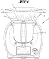
- FIG. 1 shows a food processor 1 according to the invention with a vessel 3 inserted therein and arranged on the vessel 3 cooking attachment 2.
- the food processor 1 is here for example designed as an electric motor driven agitator, which has a vessel 3 associated agitator, a vessel heater and similar facilities.
- the agitator, the heater and the like are controlled by means of a touch display or switches.
- the cooking attachment 2 has a bottom 4 with one or more bottom openings 5, through which steam emerging from the vessel 3 can enter into the cooking attachment in order to cook preparation goods contained in the cooking attachment 2. Likewise, condensate formed in the cooking attachment 2 can flow through the bottom openings 5 into the vessel in order to be available there for a renewed steam cycle.
- the cooking products 7 contained in the cooking attachment 2 can be, for example, vegetables, fish or the like.
- the cooking attachment 2 is advantageously closed by means of a lid 12, so that preferably a large part of the steam generated in the vessel 3 remains in the cooking attachment 2 and is not removed to the surroundings of the food processor 1.
- FIG. 2 shows a vertical section through a arranged on a vessel 3 cooking attachment 2 according to a first embodiment.
- the bottom 4 of the cooking attachment 2 has a plurality of bottom openings 5, which are separated by a plurality of spacers 6.
- the bottom openings 5 and the spacers 6 are arranged in rows, wherein flow channels 8 for steam flows and condensate flows remain between successive spacers 6.
- the arrangement of the spacers 6 and the arrangement of the bottom openings 5 are superimposed so that a bottom opening 5 is surrounded in the circumferential direction by a plurality of spacers 6, and that conversely a spacer 6 is surrounded by a plurality of bottom openings 5. This applies at least to the bottom openings 5 or spacers 6 arranged in a central region of the structure.
- bottom openings 5 and spacers 6 are correspondingly surrounded only over a certain peripheral portion of spacers 6 and bottom openings 5.
- the spacers 6 are formed as ribs, which are arranged parallel to adjacent ribs. Between the ribs are bottom openings 5, which are arranged in the region of the flow channels 8.
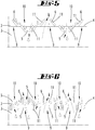
- FIG. 3 shows an enlarged plan view of a portion of the bottom 4 according to FIG. 2 ,
- the regular structure can be seen, which has a plurality of bottom openings 5 and a plurality of spacers 6.
- the bottom openings 5 are arranged in a plurality of mutually parallel rows.
- the spacers 6 are aligned in rows arranged parallel to one another, with a row of bottom openings 5 each alternating with a row of spacers 6.
- a spacer 6 is regularly surrounded by six bottom openings 5.
- Each bottom opening 5, on the other hand is surrounded either by two bottom openings 5 and two spacers 6 or by four spacers 6 and four bottom openings 5, depending on their position within the structure.
- the assignment is made by the ratio between the number of bottom openings 5 and the number of spacers 6, which is approximately 2: 1 here.
- FIG. 4 shows a cross section through adjacently arranged rows of bottom openings 5 and spacers 6.
- the rows of bottom openings 5 simultaneously form flow channels 8 for the flow of steam and / or condensate.
- the invention works in such a way that the preparation goods 7 contained in the cooking attachment 2 are spaced from the bottom openings 5 by means of the spacers 6, see above that the bottom openings 5 are not closed by the preparation goods 7. Rather, the flow channels 8 remain open between the bottom openings 5 and the preparation goods 7.
- the bottom openings 5 are at the same time steam openings 9 for the flow through the bottom opening 5 with steam and condensate openings 10 for the flow through the bottom openings 5 with condensate.
- the rising from the vessel 3 of the food processor 1 steam can flow through the bottom openings 5 in the cooking attachment 2 and are distributed there within the flow channels 8 on the bottom 4 of the cooking attachment 2.
- the hot steam preferably flows to those locations within the cooking attachment 2, which have the lowest temperature.
- a flow is made possible between the bottom 4 and the preparation goods 7 contained in the cooking attachment 2, so that a fast and homogeneous cooking result of the preparation goods 7 can be created.
- condensate is formed, which can be discharged through the flow channels 8 in the direction of the bottom openings 5.
- the condensate finally enters the vessel 3 of the food processor 1, where it is available for a renewed steam cycle.
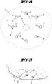
- FIGS. 5 and 6 show different embodiments of advantageous embodiments of the bottom openings 5.
- the bottom openings 5 are designed so that there are separate steam openings 9 for the flow of steam and condensate openings 10 for the flow of condensate. This is achieved in that the bottom openings 5 are surrounded by collar elements 11 whose opening cross-section tapers either in the direction of the cooking attachment 2 or in the direction of the vessel 3.
- the second opening bottom 5 shown on the left is, for example, a condensate opening 10.
- This has a collar element 11 which tapers in a direction from the interior of the cooking attachment 2 to the vessel 3.
- the protruding from the bottom 4 collar elements 11 simultaneously form spacers 6 for spacing a in
- a portion of the collar member 11 of the condensate opening 10 also forms a portion of a collar member 11 of an adjacent (in the figure to the left) steam opening 9.
- This steam opening 9 has an opening cross section, which is in a Direction of the vessel 3 tapers in the interior of the cooking attachment 2, that is, the taper extends in the direction opposite to the taper of the condensate opening 10 direction.
- the collar elements 11 have a polygonal, for example square, cross-sectional shape in a plan view, so that a partial region of a collar element 11 of a first bottom opening 5 can be formed by a partial region of a collar element 11 of an adjacent bottom opening 5.
- the collar member 11 may be formed of spaced apart individual sections, so that further flow channels 8 remain on the bottom 4 of the cooking attachment 2.
- the collar elements 11 may be substantially perpendicular to the bottom 4 of the cooking attachment 2.
- the collar element 11 can be tapered stepwise, so that, for example, the side facing the vessel 3 provides a larger opening cross-section than the side facing the interior of the cooking attachment 2.
- steam openings 9 and condensate openings 10 can again be formed next to one another, the taper running in opposite directions.
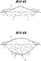
- FIG. 7 shows a third embodiment of the invention, according to which the bottom 4 of the cooking attachment 2 is inclined in the direction of the vessel 3 of the food processor 1.
- the lowest part of the inclined bottom 4 is located centrally in the middle of the bottom 4, so that in the cooking attachment 2 collected condensate can flow along the entire circumference of the bottom opening 5 to the bottom opening 5.
- the bottom 4 also has a plurality of bottom openings 5, which are formed as a steam opening 9.
- the vapor openings 9 are located with respect to the lowermost portion of the inclined bottom at a portion arranged above it, so that the condensate flows past the vapor openings 9 on its way in the direction of the condensate opening 10.
- the steam openings 9 have collar elements 11, which on the one hand serve as spacers 6 for the preparation items 7 arranged in the cooking attachment 2, and on the other hand for the protection of the vapor openings 9 against a flow through the condensate. In this way, the flows of steam and condensate, which regularly take place in opposite directions, are optimally separated from each other.
- FIG. 8 shows a plan view of a portion of the bottom 4 according to FIG. 7 , It can be seen that the condensate opening 10 in the circumferential direction of several, namely eight, steam openings 9 is surrounded. Each vapor opening 9 in this case has a collar element 11 which completely surrounds the bottom opening 5 in the circumferential direction.
- FIG. 9 shows an embodiment in which the vapor openings 9 are surrounded only in a certain peripheral portion of collar members 11.
- These collar elements 11 are advantageously located on that side of the bottom opening 5, which is first passed by a condensate flowing down the inclined bottom 4.
- the peripheral portion of the bottom opening 5, which is not protected by a collar element 11, is regularly not overflowed by condensate, since it lies deeper than the bottom opening 5.
- FIGS. 10 to 13 show inventive embodiments of a lid 12 of the cooking attachment 2, with the aid of the adhesion of condensate on the inner side of the lid 12 can be prevented.
- the FIGS. 10 and 11 show, for example, structures which are called peaks ( FIG. 10 ) or as ribs ( FIG. 11 ) are configured. These structures provide an increased surface area for condensing vapor on the lid 12.
- the FIGS. 12 and 13 show an inclined formation of the lid 12, so that formed on the inner side of the lid 12 condensate flows in the direction of the cooking attachment 2 due to gravity.
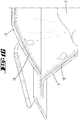
- FIG. 14 shows a fourth embodiment of the invention, in which a capillary 14 is formed on the cooking attachment 2.
- the capillary 14 is formed between a collar opening 11 delimiting a vapor opening 9 and a delimiting element 19 extending in a U-shaped manner over the collar element 11.
- the limiting element 19 is formed substantially annular and folded in the radial direction of the ring U-shaped.
- the capillary 14 advantageously has a diameter of a few ⁇ m in the radial direction of the bottom opening 5.
- the capillary 14 can be separated by walls (not shown) into individual partial capillaries.
- the capillary 14 has a first end region 15, which projects into the condensate collected on the bottom 4 of the cooking attachment 2.
- a second end region 16 of the capillary 14 is guided through the bottom opening 5 to the outside in the direction of the vessel 3. As soon as the condensate on the bottom 4 of the cooking attachment 2 comes into contact with the first end region 15, this can ascend into the capillary 14 due to the capillary effect and be conveyed in the direction of the vessel 3.
- FIGS. 15 and 16 show embodiments of a arranged on the inside of a cooking attachment 2 structure 18.
- the structure 8 according to FIG. 15 consists mutually parallel ribs, which assign substantially radially to a bottom opening 5.
- the condensate formed in the cooking attachment 2 can flow onto the bottom opening 5 between adjacent ribs.
- FIG. 16 In contrast, an embodiment is shown in which both the inside of the cooking attachment 2 and the inside of the lid 12 have different lengths of hairs.
- This structure 18 favors a solution of the condensate from the inner wall of the cooking attachment 2 or the lid 12, so that the condensate can be passed into the vessel 3 very quickly, where it is finally reheated and evaporated, to the preparation goods 7 in a new To heat cycle.
- FIG. 17 Finally shows a fifth embodiment of the invention, in which 12 vibration actuators 17 are arranged both on the cooking attachment 2 and on the lid.
- the vibration actuators 17 are here, for example, piezo-shakers, which are acted upon by means of a controller 13 so that they perform forced oscillations, which in turn are transmitted to the walls of the cooking attachment 2 and der Deckels 12. Due to the vibrations of the cooking attachment 2 or the cover 12, condensate adhering to the wall is released, so that it can quickly be returned to the vessel of the food processor 1 and is again available for heating the preparation goods 7.
Landscapes
- Engineering & Computer Science (AREA)
- Food Science & Technology (AREA)
- Cookers (AREA)
Abstract
Die Erfindung betrifft einen Garaufsatz (2) für ein aufheizbares Gefäß (3) einer Küchenmaschine (1), welcher Garaufsatz (2) einen Boden (4) mit Bodenöffnungen (5) aufweist, durch welche aus dem Gefäß (3) austretender Dampf in den Garaufsatz (2) eintreten und/ oder aus dem Garaufsatz (2) austretendes Kondensat in das Gefäß (3) eintreten kann, wobei die Bodenöffnungen (5) mindestens eine Dampföffnung (9) und mindestens eine von der Dampföffnung (9) separat ausgebildete Kondensatöffnung (10) aufweisen. Um einen Garaufsatz für ein aufheizbares Gefäß einer Küchenmaschine anzugeben, das hinsichtlich einer Kondensatöffnung vorteilhaft ausgestaltet ist, schlägt die Erfindung vor, dass die Kondensatöffnung (10) eine Kapillare (14) mit einem ersten Endbereich (15) und einem zweiten Endbereich (16) aufweist, wobei der erste Endbereich (15) im Bereich des Bodens (4) auf der dem Inneren des Garaufsatzes (2) zugewandten Seite angeordnet ist, und wobei der zweite Endbereich (16) auf der dem Gefäß (3) der Küchenmaschine (1) zugewandten Seite des Garaufsatzes (2) aus dem Garaufsatz (2) geführt ist, so dass an dem ersten Endbereich (15) befindliches Kondensat via der Kapillare (14) in das Gefäß (3) fließen kann.The invention relates to a cooking attachment (2) for a heatable vessel (3) of a food processor (1), which cooking attachment (2) has a bottom (4) with bottom openings (5), through which out of the vessel (3) exiting steam in the 2) can enter the vessel (3), the bottom openings (5) having at least one vapor opening (9) and at least one condensate opening separately formed from the vapor opening (9) ( 10). In order to specify a cooking attachment for a heatable vessel of a food processor, which is advantageously designed with regard to a condensate opening, the invention proposes that the condensate opening (10) has a capillary (14) with a first end region (15) and a second end region (16) , wherein the first end region (15) in the region of the bottom (4) on the inside of the cooking attachment (2) facing side is arranged, and wherein the second end region (16) on the said vessel (3) of the food processor (1) facing Side of the cooking attachment (2) from the cooking attachment (2) is guided, so that at the first end region (15) located condensate via the capillary (14) can flow into the vessel (3).
Description
Die Erfindung betrifft einen Garaufsatz nach den Merkmalen des Oberbegriffes des Anspruches.The invention relates to a cooking attachment according to the features of the preamble of the claim.
Garaufsätze dieser Art sind im Stand der Technik bekannt. Die Druckschrift
Aus der
Aus der
Aus der
Aus der
Aus der
Aus der
Aus der
Ausgehend von dem zuletzt vorgenannten Stand der Technik beschäftigt sich die Erfindung mit der Aufgabe, einen Garaufsatz für ein aufheizbares Gefäß einer Küchenmaschine anzugeben, das hinsichtlich einer Kondensatöffnung vorteilhaft ausgestaltet ist.Based on the last-mentioned prior art, the invention has the object to provide a cooking attachment for a heatable vessel of a food processor, which is advantageously designed with respect to a condensate opening.
Diese Aufgabe ist beim Gegenstand des Anspruches 1 gelöst, wobei darauf abgestellt ist, dass die Kondensatöffnung eine Kapillare mit einem ersten Endbereich und einem zweiten Endbereich aufweist, wobei der erste Endbereich im Bereich des Bodens auf der dem Inneren des Garaufsatzes zugewandten Seite angeordnet ist, und wobei der zweite Endbereich auf der dem Gefäß der Küchenmaschine zugewandten Seite des Garaufsatzes aus dem Garaufsatz geführt ist, so dass an dem ersten Endbereich befindliches Kondensat via der Kapillare in das Gefäß fließen kann.This object is achieved in the subject matter of claim 1, wherein it is based on the fact that the condensate opening has a capillary with a first end portion and a second end portion, wherein the first end portion is arranged in the region of the bottom on the inside of the cooking attachment facing side, and wherein the second end region is guided out of the cooking attachment on the side of the cooking attachment facing the vessel of the food processor so that condensate located at the first end region can flow into the vessel via the capillary.
Es wird bei dieser Ausgestaltung der Kapillareffekt genutzt, um in dem Garaufsatz gesammeltes Kondensat ohne Beeinflussung des entgegen gerichteten Dampfstroms in das Gefäß der Küchenmaschine zu leiten, wo es dann wieder für einen erneuten Dampfzyklus zur Verfügung steht.It is used in this embodiment, the capillary effect to direct condensate collected in the cooking attachment without affecting the counter-directed steam flow in the vessel of the food processor, where it is then available again for a renewed steam cycle.
Dazu weist der Garaufsatz eine Kapillare auf, welche ab einer bestimmten Füllhöhe mit dem in dem Garaufsatz gesammelten Kondensat in Kontakt steht. Sobald in dem Garaufsatz eine solche Menge Kondensat gebildet ist, dass der erste Teilbereich der Kapillare in das Kondensatvolumen eintaucht, wird das Kondensat aufgrund des Kapillareffektes via der Kapillare von dem Garaufsatz in das Gefäß geleitet. Die Höhe des mindestens benötigten Füllstandes kann besonders einfach durch den Abstand des ersten Endbereiches von dem Boden des Garaufsatzes variiert werden. Der Kapillareffekt setzt hierbei erst dann ein, wenn der Mindest-Füllstand innerhalb des Garaufsatzes erreicht ist.For this purpose, the cooking attachment has a capillary, which is in contact with the condensate collected in the cooking attachment at a certain filling level. As soon as such an amount of condensate is formed in the cooking attachment that the first portion of the capillary dips into the condensate volume, the condensate is conducted from the cooking attachment into the vessel due to the capillary effect via the capillary. The height of the minimum required level can be particularly easily varied by the distance of the first end portion of the bottom of the cooking attachment. The capillary effect only starts when the minimum filling level within the cooking attachment has been reached.
Die Kapillare kann auf unterschiedliche Art und Weise ausgebildet sein. Beispielsweise kann diese ein Schlauch, Rohr oder dergleichen mit einem Durchmesser von vorzugsweise nur wenigen µm sein. Je kleiner der Durchmesser ist, desto größer sind der Kapillardruck und der zurückgelegte Weg der Flüssigkeit innerhalb der Kapillare.The capillary can be designed in different ways. For example, this may be a hose, pipe or the like with a diameter of preferably only a few microns. The smaller the diameter, the greater the capillary pressure and the distance traveled by the liquid within the capillary.
Gemäß einer Variante kann eine Wandung der Kapillare durch ein Kragenelement des Bodens des Garaufsatzes gebildet sein, welches eine Dampföffnung umgibt. Dieses Kragenelement steht von dem Boden ab und bildet einen Sammelbereich für in dem Garaufsatz gebildetes Kondensat. Es wird vorgeschlagen, dieses Kragenelement mit einem senkrecht zur Umfangsrichtung U-förmig gekrümmten Ring zu überdecken, welcher mit einem ersten Endbereich der U-Form in den Kondensat-Sammelbereich eingreift und mit einem zweiten Endbereich der U-Form in die Dampföffnung. Dabei bildet sich zwischen dem Kragenelement und dem U-förmigen Ring eine U-förmige Kapillare aus, deren Durchmesser in radialer Richtung beispielsweise durch Abstandshalter eingestellt werden kann.According to a variant, a wall of the capillary can be formed by a collar element of the bottom of the cooking attachment, which surrounds a vapor opening. This collar element protrudes from the bottom and forms a collecting area for condensate formed in the cooking attachment. It is proposed to cover this collar element with a ring curved in a U-shape perpendicular to the circumferential direction, which engages with a first end region of the U-shape in the condensate collecting region and with a second end region of the U-shape into the vapor opening. Here, a U-shaped capillary is formed between the collar member and the U-shaped ring, the diameter of which can be adjusted in the radial direction, for example by spacers.
In Umfangsrichtung können einzelne Teil-Kapillare ausgebildet sein, beispielsweise durch an dem Ring und/ oder an dem Kragenelement angeordnete Rippen. Der Kapillareffekt funktioniert dabei wie im Stand der Technik bekannt so, dass das an dem ersten Endbereich der Kapillare stehende Kondensat aufgrund der Oberflächenspannung in die Kapillare aufsteigen kann. Durch eine Störung der Oberflächenspannung im Bereich des zweiten Endbereichs kann die Flüssigkeit wieder aus der Kapillare austreten. Diese Störung kann bspw. durch einen in die Kapillare hineinragenden Docht oder ähnliches bewirkt werden.In the circumferential direction, individual partial capillaries may be formed, for example by ribs arranged on the ring and / or on the collar element. The capillary effect works as known in the art so that the standing on the first end of the capillary condensate due to the surface tension can ascend into the capillary. By disturbing the surface tension in the region of the second end region, the liquid can emerge from the capillary again. This disorder can be effected, for example, by a wick protruding into the capillary or the like.
Weiter kann der Boden des Garaufsatzes auf der in Richtung des Inneren des Garaufsatzes gewandten Seite eine Mehrzahl von von dem Boden abstehenden Abstandshaltern zur Beabstandung eines in dem Garaufsatz enthaltenen Zubereitungsgutes von der Bodenöffnung aufweisen, wobei eine Bodenöffnung in Umfangsrichtung zumindest teilweise von den Abstandshaltern umgeben ist.Furthermore, the bottom of the cooking attachment may have a plurality of spacers protruding from the bottom for spacing a cooking product contained in the cooking attachment from the bottom opening on the side facing the interior of the cooking attachment, with a bottom opening circumferentially at least partially surrounded by the spacers.
Das in dem Garaufsatz enthaltene Zubereitungsgut wird hierbei mittels der Abstandshalter von dem Boden des Garaufsatzes ferngehalten. Dadurch liegt das Zubereitungsgut nicht mehr unmittelbar an den Bodenöffnungen an und verschließt diese im ungünstigen Fall, sondern es wird ein Freiraum zwischen einer Bodenöffnung und dem Zubereitungsgut geschaffen, in welchen aus dem Gefäß austretender Dampf eintreten kann und durch welchen in dem Garaufsatz gebildetes Kondensat in Richtung des Gefäßes der Küchenmaschine austreten kann. Dadurch, dass die Zubereitungsgüter nun nicht mehr unmittelbar auf den Bodenöffnungen liegen, wird der Strömungswiderstand für die durch die Bodenöffnung strömenden Kondensat- bzw. Dampfströme verringert. Dadurch wird eine schnellere Zubereitung des Zubereitungsgutes ermöglicht, ohne die Heizleistung des Gefäßes der Küchenmaschine erhöhen zu müssen. Darüber hinaus kann auch das in dem Garaufsatz gebildete Kondensat schneller in das Gefäß der Küchenmaschine strömen, so dass dieses für eine erneute Erwärmung zur Verfügung steht und somit insgesamt weniger Wasser für den Dampfkreislauf benötigt wird. Durch die geringer benötigte Menge Flüssigkeit wird gleichzeitig auch die Aufheizphase bis zur Dampfbildung innerhalb des Gefäßes reduziert. Um die Bodenöffnung für Dampf- bzw. Kondensatströme aus unterschiedlichen Strömungsrichtungen offenzuhalten, wird die Bodenöffnung in Umfangsrichtung von mehreren Abstandshaltern umgeben. Die Abstandshalter sollten die Bodenöffnung zumindest in einem Winkelbereich von 90° umgeben. Bevorzugt ist jedoch eine Ausführungsform, bei welcher die Bodenöffnung vollständig, d. h. in einem Winkelbereich von 360°, von Abstandshaltern umgeben ist, beispielsweise von äquidistant entlang des Umfangs angeordneten Abstandshaltern.The cooking product contained in the cooking attachment is kept away from the bottom of the cooking attachment by means of the spacers. As a result, the preparation material is no longer directly adjacent to the bottom openings and closes them in the worst case, but it creates a space between a bottom opening and the preparation material, in which emerging from the vessel steam can enter and through which formed in the cooking attachment condensate in the direction of the vessel of the food processor can emerge. Due to the fact that the preparation goods no longer lie directly on the bottom openings, the flow resistance for the condensate or vapor streams flowing through the bottom opening is reduced. As a result, a faster preparation of the preparation material is possible without having to increase the heating power of the vessel of the food processor. In addition, the condensate formed in the cooking attachment can flow faster into the vessel of the food processor, so that it is available for reheating and thus less total water is needed for the steam cycle. Due to the lower amount of liquid required at the same time also the heating phase is reduced to vapor formation within the vessel. In order to keep open the bottom opening for steam or condensate flows from different flow directions, the bottom opening is surrounded in the circumferential direction by a plurality of spacers. The spacers should surround the bottom opening at least in an angular range of 90 °. Prefers However, an embodiment in which the bottom opening is completely, ie in an angular range of 360 °, surrounded by spacers, for example, of equidistantly arranged along the circumference spacers.
Es wird vorgeschlagen, dass der Boden des Garaufsatzes eine Anordnung einer Mehrzahl von Bodenöffnungen und eine Anordnung einer Mehrzahl von Abstandshaltern aufweist, wobei die Anordnung der Abstandshalter die Anordnung der Bodenöffnungen so überlagert, dass eine Bodenöffnung in Umfangsrichtung von mehreren Abstandshaltern umgeben ist, und dass ein Abstandshalter von mehreren Bodenöffnungen umgeben ist. Gemäß dieser Ausführungsform weist der Boden des Garaufsatzes eine Kombination von Bodenöffnungen und Abstandshaltern auf, so dass jeder Bodenöffnung eine Mehrzahl von Abstandshaltern und jedem Abstandshalter eine Mehrzahl von Bodenöffnungen zugeordnet ist. Es ergibt sich somit eine Ausbildung des Bodens, welche im Bereich einer beliebig großen Fläche den vereinfachten Austausch von Dampf bzw. Kondensat zwischen dem Garaufsatz und dem Gefäß der Küchenmaschine erlaubt. Dabei kann beispielsweise eine Bodenöffnung, welche in der Mitte dieser Fläche angeordnet ist, entlang ihres gesamten Umfangs von sowohl Abstandshaltern als auch weiteren Bodenöffnungen umgeben sein, während eine Bodenöffnung, welche Teil des Randbereiches dieser Fläche ist, nur unvollständig von Abstandshaltern bzw. auch Bodenöffnungen umgeben ist. Die sich überlappenden Anordnungen von Bodenöffnungen und Abstandshaltern können dabei regelmäßig oder unregelmäßig ausgebildet sein, so dass jeder Bodenöffnung im Wesentlichen eine gleiche Anzahl oder eine abweichende Anzahl von Abstandshaltern zugeordnet ist.It is proposed that the bottom of the cooking attachment has an arrangement of a plurality of bottom openings and an arrangement of a plurality of spacers, wherein the arrangement of the spacers superimposed on the arrangement of the bottom openings so that a bottom opening in the circumferential direction is surrounded by a plurality of spacers, and that Spacer is surrounded by several bottom openings. According to this embodiment, the bottom of the cooking attachment has a combination of bottom openings and spacers so that each bottom opening is associated with a plurality of spacers and each spacer with a plurality of bottom openings. This results in a design of the soil, which allows the simplified exchange of steam or condensate between the cooking attachment and the vessel of the food processor in the area of any large area. In this case, for example, a bottom opening, which is arranged in the center of this surface, be surrounded along its entire circumference by both spacers and other bottom openings, while a bottom opening, which is part of the edge region of this surface, only incompletely surrounded by spacers or bottom openings is. The overlapping arrangements of bottom openings and spacers can be formed regularly or irregularly, so that each bottom opening is assigned an essentially equal number or a different number of spacers.
Es wird insbesondere vorgeschlagen, dass die Anordnung der Bodenöffnungen und die Anordnung der Abstandshalter eine regelmäßige, zumindest zweidimensionale Struktur bilden, in welcher zwischen in Bezug auf eine erste Richtung aufeinanderfolgenden Abstandshaltern ein sich in eine von der ersten Richtung abweichende zweite Richtung erstreckender, aufeinander folgende Bodenöffnungen aufweisender Strömungskanal für Dampf und/oder Kondensat ausgebildet ist. Durch die erfindungsgemäße regelmäßige Struktur der in dem Boden ausgebildeten Bodenöffnungen und an dem Boden angeordneten Abstandshalter können gezielt Strömungskanäle für eine widerstandsarme Strömung von Dampf und/oder Kondensat ausgebildet sein. Die Abstandshalter bilden dabei zumindest örtlich begrenzte Wandungsabschnitte eines Strömungskanals, so dass der Dampf bzw. das Kondensat zu einem großen Teil innerhalb des Strömungskanals verbleibt, welcher eine Strömungsverbindung zu den Bodenöffnungen aufweist. Da jedem Strömungskanal eine Vielzahl von Bodenöffnungen zugeordnet ist, wird eine besonders schnelle Abführung des Kondensates aus dem Garaufsatz in das Gefäß der Küchenmaschine ermöglicht. Das Kondensat steht somit nicht an einer einzigen Bodenöffnung an, sondern kann auf eine Vielzahl von hintereinander angeordnete Bodenöffnungen verteilt werden, so dass beispielsweise eine Verstopfung einer einzelnen Bodenöffnung nicht zu einer maßgeblichen Reduzierung der Kondensatströmung führt. Ebenso kann auch aus dem Gefäß in den Garaufsatz aufsteigender Dampf durch eine Vielzahl von Bodenöffnungen in den Garaufsatz gelangen, wobei die durch unterschiedliche Bodenöffnungen strömenden Dampfanteile in den jeweils zugeordneten Strömungskanälen gesammelt werden und von dort aus zu einem Teilbereich des Bodens des Garaufsatzes strömen, welcher eine geringste Temperatur aufweist. Dort kann der Dampf beispielsweise an einer Wandung des Garaufsatzes oder auch an den in dem Garaufsatz enthaltenen Zubereitungsgütern kondensieren und entsprechend die Wärmeenergie für den Garprozess übertragen. Anschließend gelangt das entstehende Kondensat über die Strömungskanäle zurück zu den Bodenöffnungen und damit auch in das Gefäß der Küchenmaschine, wo es für einen erneuten Dampfzyklus zur Verfügung steht.It is in particular proposed that the arrangement of the bottom openings and the arrangement of the spacers form a regular, at least two-dimensional structure, in which between successive with respect to a first direction spacers extending in a deviating from the first direction second direction, successive bottom openings exhibiting flow channel for steam and / or condensate is formed. By the invention The regular structure of the bottom openings formed in the bottom and spacers arranged on the bottom can be designed specifically for flow channels for a low-resistance flow of steam and / or condensate. The spacers form at least locally limited wall sections of a flow channel, so that the steam or the condensate remains to a large extent within the flow channel, which has a flow connection to the bottom openings. Since each flow channel is associated with a plurality of bottom openings, a particularly rapid removal of the condensate from the cooking attachment is made possible in the vessel of the food processor. The condensate is thus not at a single bottom opening, but can be distributed to a plurality of successively arranged bottom openings, so that, for example, a blockage of a single bottom opening does not lead to a significant reduction in the condensate flow. Likewise, steam rising from the vessel into the cooking attachment can also pass through a multiplicity of bottom openings into the cooking attachment, the vapor components flowing through different bottom openings being collected in the respective associated flow channels and flowing from there to a subregion of the bottom of the cooking attachment, which one lowest temperature. There, the steam can condense, for example, on a wall of the cooking attachment or on the preparation goods contained in the cooking attachment and transmit the heat energy for the cooking process accordingly. Subsequently, the resulting condensate passes through the flow channels back to the bottom openings and thus into the vessel of the food processor, where it is available for a new steam cycle.
Es wird vorgeschlagen, dass die Abstandshalter Zinnen, Nocken, Zylinder, Rippen, Spitzen, Pyramiden, Filamente und/oder Riffel aufweisen. Grundsätzlich eignen sich jedoch auch andere Formen zur Ausbildung von Abstandshaltern. Wichtig ist, dass die Abstandshalter die Beabstandung der Zubereitungsgüter von dem Boden des Garaufsatzes ermöglichen, so dass die Bodenöffnungen freigehalten werden. Die konkrete Anordnung der Abstandshalter und deren Form sollten somit ermöglichen, dass Kondensat unter jeglicher Art von Zubereitungsgütern hindurch in Richtung der Bodenöffnungen fließen kann. Ebenso sollen die Bodenöffnungen auch zur Durchströmung von Dampf aus dem Gefäß in den Garaufsatz freigehalten werden. Sofern es sich bei den Abstandshaltern beispielsweise um Rippen, Filamente oder Riffel mit einer nicht zu vernachlässigenden Längserstreckung handelt, sollten diese in Richtung ihrer Längserstreckung Unterbrechungen aufweisen, damit der Dampf und/oder das Kondensat auch quer zu der Längserstreckung der Abstandshalter strömen kann und somit aus dem jeweiligen Strömungskanal herausströmen kann.It is proposed that the spacers have pinnacles, cams, cylinders, ribs, tips, pyramids, filaments and / or corrugations. In principle, however, other forms are also suitable for forming spacers. It is important that the spacers allow the spacing of the preparations from the bottom of the cooking attachment so that the bottom openings are kept clear. The concrete arrangement of the spacers and their shape should thus enable that condensate can flow under any kind of preparation goods in the direction of the bottom openings. Likewise, the bottom openings should also be kept free for the flow of steam from the vessel into the cooking attachment. If the spacers are, for example, ribs, filaments or corrugations with a non-negligible longitudinal extent, they should have interruptions in the direction of their longitudinal extent so that the vapor and / or the condensate can also flow transversely to the longitudinal extent of the spacers and thus out can flow out of the respective flow channel.
Weiter kann sich die Dampföffnung in eine Dampfströmungsrichtung von dem Gefäß in das Innere des Garaufsatzes verjüngen, während sich die Kondensatöffnung in eine Kondensatströmungsrichtung von dem Inneren des Garaufsatzes in das Gefäß verjüngt.Further, the vapor opening may taper in a vapor flow direction from the vessel to the interior of the cooking attachment while the condensate port tapers in a direction of condensate flow from the interior of the cooking attachment into the vessel.
Hierbei werden die Bodenöffnungen in Dampföffnungen zum Durchtritt von Dampf aus dem Gefäß in den Garaufsatz und Kondensatöffnungen zum Durchtritt von Kondensat aus dem Garaufsatz in das Gefäß der Küchenmaschine geteilt. Durch diese separate Ausbildung lassen sich die in Bezug auf ihre Strömungsrichtungen abweichenden Strömungen optimieren, insbesondere ist eine schnellere Strömung des Kondensats in Richtung der Bodenöffnung und ein widerstandsarmer Durchtritt des Dampfes bzw. Kondensats durch die Bodenöffnungen möglich. Vorteilhaft wird der aus dem Gefäß nach oben strömende Dampf nicht durch das aus dem Garaufsatz ausströmende Kondensat behindert. Die Unterscheidung der Bodenöffnungen in Dampföffnungen und Kondensatöffnungen erfolgt durch ihre Formgestaltung. Durch die Verjüngung der Bodenöffnungen in eine der Strömungsrichtungen (Dampf/Kondensat) ergibt sich ein vergrößerter Öffnungsquerschnitt auf einer Seite der Bodenöffnung, während sich auf der gegenüberliegenden Seite des Bodens ein verringerter Öffnungsquerschnitt ergibt. Dadurch gelangt das auf einer Seite des Bodens entlang strömende Medium, das heißt entweder der Dampf oder das Kondensat, bevorzugt durch diejenigen Bodenöffnungen, welche den größeren Öffnungsquerschnitt zur Verfügung stellen. Erfindungsgemäß sind die Bodenöffnungen nun so ausgebildet, dass einige der Bodenöffnungen in Richtung des Gefäßes und andere Bodenöffnungen in Richtung des Garaufsatzes verjüngt sind. Insofern durchströmt bevorzugt das Kondensat bzw. der Dampf die Bodenöffnungen. Die gleichzeitige Durchströmung derselben Bodenöffnung durch sowohl Dampf als auch Kondensat wird erheblich reduziert, so dass der Strömungswiderstand deutlich reduziert ist und somit eine schnellere Strömungsgeschwindigkeit erreicht werden kann, was wiederum zu einer schnelleren Zubereitung der in dem Garaufsatz enthaltenen Zubereitungsgüter führt. Durch die Verjüngung der Bodenöffnung entsteht eine trichterförmige Öffnung, welche jedoch in Bezug auf einen Querschnitt nicht rund sein muss, sondern auch oval, quadratisch, polygonal oder auf ähnliche Art und Weise ausgebildet sein kann. Die Steigung der Verjüngung kann dabei ebenfalls variabel sein. Beispielsweise kann die Steigung einen Winkel von 45° zur Flächennormalen der Öffnungsebene aufweisen. Alternativ zu einem stetigen Verlauf der Verjüngung ist es auch möglich, dass die Verjüngung stufenartig erfolgt, so dass Teilbereiche der Bodenöffnung einen Winkel von 90° zu der Flächennormalen der Öffnungsebene aufweisen.Here, the bottom openings are divided into steam openings for the passage of steam from the vessel into the cooking attachment and condensate openings for the passage of condensate from the cooking attachment into the vessel of the food processor. By means of this separate embodiment, the deviations with respect to their flow directions can be optimized, in particular a faster flow of the condensate in the direction of the bottom opening and a low-resistance passage of the steam or condensate through the bottom openings is possible. Advantageously, the steam flowing upwards from the vessel is not hindered by the condensate flowing out of the cooking attachment. The distinction of the bottom openings in the steam openings and condensate openings is made by their design. The tapering of the bottom openings in one of the flow directions (steam / condensate) results in an enlarged opening cross section on one side of the bottom opening, while a reduced opening cross section results on the opposite side of the bottom. As a result, the medium flowing along one side of the bottom, that is to say either the vapor or the condensate, preferably passes through those bottom openings which provide the larger opening cross-section. According to the invention, the bottom openings are now formed so that some of the bottom openings are tapered in the direction of the vessel and other bottom openings in the direction of the cooking attachment. In this respect, preferably the condensate or the steam flows through the bottom openings. The simultaneous flow through the same bottom opening by both steam and condensate is considerably reduced, so that the flow resistance is significantly reduced and thus a faster flow rate can be achieved, which in turn leads to a faster preparation of the cooking product contained in the cooking attachment. The tapering of the bottom opening creates a funnel-shaped opening which, however, does not have to be round with respect to a cross-section, but may also be oval, square, polygonal or similar. The slope of the taper can also be variable. For example, the slope may have an angle of 45 ° to the surface normal of the opening plane. As an alternative to a steady course of the taper, it is also possible for the taper to be stepped, so that portions of the bottom opening have an angle of 90 ° to the surface normal of the opening plane.
Des Weiteren wird vorgeschlagen, dass der Bodenöffnung auf der in Richtung des Garaufsatzes gewandten Seite und/oder auf der in Richtung des Gefäßes gewandten Seite ein von dem Boden abstehendes Kragenelement zugeordnet ist. Das Kragenelement kann dabei die Verjüngung des Öffnungsquerschnitts der Bodenöffnung in Richtung des Gefäßes bzw. des Garaufsatzes fortsetzen. Alternativ ist es auch möglich, dass nur das Kragenelement eine Verjüngung aufweist, nicht jedoch die Bodenöffnung. Das Kragenelement kann beispielsweise ein in einem bestimmten Winkel zu der Senkrechten der Öffnungsebene stehendes Kragenelement sein. Das Kragenelement kann dabei einstückig mit dem Boden des Garaufsatzes oder auch als separates Kragenelement ausgebildet sein. Durch die sich verjüngende Ausbildung, nach welcher das Kragenelement im Wesentlichen die Form eines Trichters aufweist, kann auf der den größeren Öffnungsquerschnitt aufweisenden Seite des Bodens eine größere Menge des Strömungsmediums in Richtung der Bodenöffnung geleitet werden als auf der gegenüberliegenden Seite der Bodenöffnung, auf welcher das Kragenelement lediglich einen kleinen Öffnungsquerschnitt bereitstellt. Grundsätzlich kann das Kragenelement unterschiedliche Formgestaltungen aufweisen. Beispielsweise kann sich das Kragenelement stetig aufweiten oder alternativ dazu stufenartig. Insbesondere empfiehlt es sich, dass ein Abstand zwischen zwei Bodenöffnungen und eine Formgestaltung der zugehörigen Kragenelemente so korrespondiert, dass die Kragenelemente der Bodenöffnungen gleichzeitig ein Kragenelement einer dazwischen angeordneten Bodenöffnung bilden. Dieses Kragenelement weist dann im Gegensatz zu den beiden anderen Kragenelementen in Bezug auf dieselbe Seite des Bodens, auf welcher die Kragenelemente der beiden anderen Bodenöffnungen aufgeweitet sind, eine Verjüngung auf. Dadurch entsteht eine Struktur, in welcher die Kragenelemente benachbarter Bodenöffnungen in entgegengesetzte Richtungen verjüngt sind. Insbesondere empfiehlt sich diese Struktur beispielsweise bei Kragenelementen, welche einen rechteckigen Querschnitt aufweisen. Der Boden des Garaufsatzes weist somit eine Vielzahl von Bodenöffnungen auf, deren Kragenelemente abwechselnd in Bezug auf unterschiedliche Durchströmungsrichtungen verjüngt bzw. aufgeweitet sind, so dass einerseits Dampföffnungen für den widerstandsarmen Durchtritt von Dampf, und andererseits Kondensatöffnungen für einen widerstandsarmen Durchtritt von Kondensat gebildet sind. Durch diese Ausgestaltung werden die Kondensatströmung und die Dampfströmung voneinander getrennt, so dass beispielsweise das in das Gefäß fließende Kondensat nicht den nach oben strömenden Dampf behindert. Das Kondensat fließt über die geneigten Flächen der Kragenelemente, welche gleichzeitig als Abstandshalter für die in dem Gargefäß enthaltenen Zubereitungsgüter dienen, in Richtung der Bodenöffnungen und schließlich entlang der Verjüngung der Kragenelemente in Richtung des Gefäßes. Demgegenüber schirmen diejenigen Kragenelemente, deren verjüngter Öffnungsquerschnitt in Richtung des Inneren des Gargefäßes zeigt, die Bodenöffnung gegenüber einem Durchtritt von Kondensat ab, so dass diese für den nach oben gerichteten Dampfstrom freibleiben. Grundsätzlich können die Kragenelemente unterschiedlich geformte Öffnungsquerschnitte aufweisen, beispielsweise denkbar sind rund, eckige oder polygonal geformte Querschnitte. Die Öffnungsquerschnitte der zur Durchströmung von Dampf vorgesehenen Bodenöffnungen bzw. Kragenelemente sollte dabei vorteilhaft größer sein als ein entsprechender Öffnungsquerschnitt für eine Dampfströmung. In der Praxis hat sich ein Verhältnis der Öffnungsquerschnitte von Dampf zu Wasser von ungefähr 10 : 1 als vorteilhaft herausgestellt, das heißt, dass die zur Durchströmung von Dampf bereitgestellte Fläche ungefähr das Zehnfache der für einen Durchtritt von Kondensat bereitgestellten Fläche betragen sollte.Furthermore, it is proposed that the bottom opening is assigned on the facing in the direction of the cooking attachment side and / or on the side facing in the direction of the vessel a protruding from the bottom collar element. The collar element can continue the tapering of the opening cross-section of the bottom opening in the direction of the vessel or the cooking attachment. Alternatively, it is also possible that only the collar element has a taper, but not the bottom opening. The collar element may, for example, be a collar element that is at a certain angle to the vertical of the opening plane. The collar element may be formed integrally with the bottom of the cooking attachment or as a separate collar element. Due to the tapered design, according to which the collar element essentially has the shape of a funnel, a larger amount of the flow medium can be directed in the direction of the bottom opening on the side of the bottom having the larger opening cross section than on the opposite side of the bottom opening on which the collar element only provides a small opening cross-section. In principle, the collar element can have different shape configurations. For example, the collar element may expand steadily or alternatively stepwise. In particular, it is recommended that a distance between two bottom openings and a shape design of the associated collar elements correspond so that the collar elements of the bottom openings simultaneously form a collar element of a bottom opening arranged therebetween. This collar element then has a taper in relation to the other two collar elements with respect to the same side of the bottom on which the collar elements of the two other bottom openings are widened. This results in a structure in which the collar elements of adjacent bottom openings are tapered in opposite directions. In particular, this structure is recommended, for example, in collar elements which have a rectangular cross-section. The bottom of the cooking attachment thus has a multiplicity of bottom openings whose collar elements are alternately tapered or widened with respect to different flow directions, so that steam openings for the low-resistance passage of steam, on the one hand, and condensate openings for a low-resistance passage of condensate on the other hand are formed. By this configuration, the condensate flow and the steam flow are separated from each other, so that, for example, the condensate flowing into the vessel does not hinder the upwardly flowing vapor. The condensate flows over the inclined surfaces of the collar elements, which also serve as spacers for the preparation goods contained in the cooking vessel, in the direction of the bottom openings and finally along the taper of the collar elements in the direction of the vessel. In contrast, those collar elements whose tapered opening cross-section points in the direction of the interior of the cooking vessel shield the bottom opening with respect to a passage of condensate, so that they remain free for the upwardly directed vapor flow. In principle, the collar elements may have differently shaped opening cross-sections, for example conceivable are round, polygonal or angular cross-sections. The opening cross sections of the provided for the flow of steam bottom openings or collar elements should be advantageously greater than a corresponding Opening cross-section for a vapor flow. In practice, a vapor to water opening area ratio of about 10: 1 has been found advantageous, that is, the area provided for vapor flow should be about ten times the area provided for condensate passage.
Des Weiteren kann der Boden bezogen auf eine horizontale Ebene der auf einer horizontalen Arbeitsfläche stehenden Küchenmaschine zumindest teilweise in Richtung des Gefäßes geneigt sein, wobei die Bodenöffnung, insbesondere eine Kondensatöffnung zum Austreten von Kondensat aus dem Garaufsatz in das Gefäß, in Bezug auf eine vertikale Richtung in einem untersten Teilbereich des geneigten Bodens angeordnet ist.Furthermore, the floor may be inclined at least partially in the direction of the vessel with respect to a horizontal plane of the food processor standing on a horizontal working surface, wherein the bottom opening, in particular a condensate opening for the escape of condensate from the cooking attachment into the vessel, with respect to a vertical direction is arranged in a lowermost portion of the inclined floor.
Durch die Neigung des Bodens relativ zu einer horizontalen Ebene wird der Abfluss von Kondensat aus dem Garaufsatz via der Bodenöffnung in das Gefäß der Küchenmaschine erleichtert. Dazu ist die Bodenöffnung vorteilhaft in einem untersten Teilbereich des geneigten Bodens, besonders vorteilhaft an einem tiefsten Punkt, angeordnet. Die für den Durchtritt eines Dampfstroms vorgesehenen Bodenöffnungen, das heißt Dampföffnungen, sind entsprechend in einem höher liegenden Teilbereich des geneigten Bodens angeordnet, welcher über dem untersten Teilbereich liegt. Insofern erfolgt auch gemäß dieser Ausführungsvariante eine Trennung des Kondensatstroms von dem Dampfstrom, so dass der Garprozess optimiert werden kann.Due to the inclination of the soil relative to a horizontal plane, the drainage of condensate from the cooking attachment via the bottom opening in the vessel of the food processor is facilitated. For this purpose, the bottom opening is advantageously arranged in a lowermost portion of the inclined bottom, particularly advantageously at a lowest point. The measures provided for the passage of a vapor stream bottom openings, that is, steam openings are arranged correspondingly in a higher lying portion of the inclined bottom, which lies above the lowest portion. In this respect, according to this embodiment, a separation of the condensate flow from the steam flow, so that the cooking process can be optimized.
Vorteilhaft ist der unterste Teilbereich des geneigten Bodens in einem Zentralbereich des Bodens oder in einem Randbereich des Bodens ausgebildet. Gemäß einer ersten Ausführungsform, bei welcher der unterste Teilbereich zentral an dem Boden angeordnet ist, ist der Boden insgesamt trichterförmig ausgebildet, wobei Kondensat vorteilhaft von allen Seiten radial auf die in dem untersten Teilbereich angeordnete Kondensatöffnung zuströmt. Gemäß einer zweiten Ausführungsform ist die Kondensatöffnung in einem Randbereich des Bodens ausgebildet. Dabei liegt der Randbereich des Bodens - in Bezug auf eine vertikale Richtung der Küchenmaschine - tiefer als ein Zentralbereich. Das in dem Garaufsatz entstehende Kondensat wird somit in den Randbereich des Bodens geführt, wo es schließlich durch die Kondensatöffnung in das Gefäß der Küchenmaschine gelangen kann. Besonders vorteilhaft kann der Randbereich des Bodens als ringförmiger Bereich ausgebildet sein, entlang dessen Umfangsrichtung eine Vielzahl von Kondensatöffnungen nebeneinander angeordnet ist.Advantageously, the lowest portion of the inclined bottom is formed in a central region of the bottom or in an edge region of the bottom. According to a first embodiment, in which the lowermost subregion is arranged centrally on the ground, the bottom is designed overall funnel-shaped, with condensate advantageously flowing radially from all sides onto the condensate opening arranged in the lowermost subregion. According to a second embodiment, the condensate opening is formed in an edge region of the bottom. The edge area of the floor - in relation to a vertical direction of the food processor - lies deeper than a central area. The resulting in the cooking attachment condensate is thus guided into the edge region of the soil, where it can eventually pass through the condensate opening in the vessel of the food processor. Particularly advantageously, the edge region of the bottom can be formed as an annular region, along whose circumferential direction a plurality of condensate openings is arranged side by side.
Es wird vorgeschlagen, dass zumindest ein in Bezug auf den untersten Teilbereich des geneigten Bodens darüber angeordneter Teilbereich des Bodens zumindest eine Dampföffnung zum Eintreten von aus dem Gefäß austretendem Dampf in den Garaufsatz aufweist, wobei zumindest ein von dem untersten Teilbereich abgewandter Umfangsabschnitt der Dampföffnung ein von dem Boden abstehendes Kragenelement aufweist. Das Kragenelement schützt die Dampföffnung vor einem Durchtritt der in Richtung des Gefäßes strömenden Kondensatströme. Es empfiehlt sich, dass zumindest derjenige Umfangsabschnitt der Dampföffnung ein Kragenelement aufweist, welcher dem untersten Teilbereich des Bodens abgewandt ist, das heißt von der Kondensatöffnung weg zeigt. Dies ist gleichzeitig die Richtung, welche der Strömungsrichtung der Kondensatströmung entgegensteht. Besonders vorteilhaft ist das Kragenelement jedoch ringförmig entlang des gesamten Umfanges der Bodenöffnung angeordnet, so dass die Bodenöffnung von allen Seiten vor einer Durchströmung von Kondensat geschützt ist. Demgegenüber kann jedoch weiterhin der aus dem Gefäß der Küchenmaschine aufsteigende Dampf in den Garaufsatz gelangen, insbesondere ohne Wechselwirkung mit der Kondensatströmung.It is proposed that at least one partial area of the floor arranged above the lowest subarea of the inclined floor has at least one steam opening for the entry of steam emerging from the vessel into the cooking top, at least one peripheral section of the steam opening facing away from the lowermost partial area being one of having the floor projecting collar element. The collar member protects the vapor opening from passage of the condensate streams flowing in the direction of the vessel. It is recommended that at least that peripheral portion of the steam opening has a collar element which faces away from the lowermost portion of the bottom, that is, points away from the condensate opening. This is at the same time the direction which precludes the flow direction of the condensate flow. However, the collar element is particularly advantageously arranged annularly along the entire circumference of the bottom opening, so that the bottom opening is protected against flow of condensate from all sides. In contrast, however, continue to rise from the vessel of the food processor rising steam in the cooking attachment, in particular without interaction with the condensate flow.
Es wird auch vorgeschlagen, dass in dem Garaufsatz und/oder einem den Garaufsatz verschließenden Deckel ein Schwingungsaktor zur Erzeugung einer erzwungenen Schwingung des Garaufsatzes und/oder des Deckels zugeordnet ist, wobei die Schwingung geeignet ist, Kondensat von dem Garaufsatz und/oder dem Deckel zu lösen, so dass dieses in Richtung des Gefäßes fließen kann. Vorteilhaft kann diese Ausführungsvariante der Erfindung auch mit Merkmalen der zuvor erläuterten Ausführungsvarianten kombiniert werden.It is also proposed that in the cooking attachment and / or a cover closing the cooking attachment, a vibration actuator is associated with generating a forced oscillation of the cooking attachment and / or the cover, the oscillation being suitable for condensate from the cooking attachment and / or the cover solve, so that this can flow in the direction of the vessel. Advantageously, this embodiment of the invention can also be combined with features of the previously explained embodiments.
Hierbei liegt die Erkenntnis zugrunde, dass an einer Wandung des Garaufsatzes und/oder des Deckels anhaftendes Kondensat durch Schwingungen der Wandung von der Wandung gelöst werden kann und somit unmittelbar nach der Kondensatbildung in Richtung der Bodenöffnung strömt. Die erzwungene Schwingung des Garaufsatzes und/oder des Deckels ist dabei so auszulegen, dass deren Frequenz und Amplitude geeignet ist, die Kondensattropfen von der Wandung zu lösen. Grundsätzlich kann der Schwingungsaktor ein separat an dem Garaufsatz und/oder dem Deckel angeordneter Erreger, wie beispielsweise ein Piezo-Shaker, sein.This is based on the finding that adhering to a wall of the cooking attachment and / or the lid condensate can be released by vibrations of the wall of the wall and thus flows immediately after the condensation in the direction of the bottom opening. The forced oscillation of the cooking attachment and / or the lid is to be interpreted in such a way that its frequency and amplitude are suitable for releasing the condensate droplets from the wall. In principle, the vibration actuator may be a pathogen arranged separately on the cooking attachment and / or the cover, such as a piezo shaker.
Alternativ kann der Schwingungsaktor auch ein Elektromotor der Küchenmaschine sein. Besonders geeignet ist hierzu ein Reluktanzmotor, dessen Spulen derart angesteuert werden, dass eine zum Lösen des Kondensates von der Wandung geeignete Schwingung erzeugt wird.Alternatively, the vibration actuator may also be an electric motor of the food processor. Particularly suitable for this purpose is a reluctance motor whose coils are driven in such a way that a vibration suitable for releasing the condensate from the wall is generated.
Des Weiteren werden mit der Erfindung zusätzliche Maßnahmen zur schnellen Abführung des Kondensats aus dem Garaufsatz in Richtung des Gefäßes der Küchenmaschine vorgeschlagen. Die im Folgenden dargestellten Merkmale können dabei in Kombination mit jeder der zuvor erläuterten Ausführungsvarianten kombiniert werden.Furthermore, the invention proposes additional measures for the rapid removal of the condensate from the cooking attachment in the direction of the vessel of the food processor. The features shown below can be combined in combination with each of the previously described embodiments.
Beispielsweise wird vorgeschlagen, dass der Garaufsatz einen Deckel aufweist, dessen in Richtung des Inneren des Garaufsatzes gewandte Seite bezogen auf eine horizontale Ebene des Garaufsatzes zumindest teilweise in Richtung des Bodens des Garaufsatzes geneigt ist.For example, it is proposed that the cooking attachment has a lid whose side facing the interior of the cooking attachment is inclined at least partially in the direction of the bottom of the cooking attachment with respect to a horizontal plane of the cooking attachment.
Darüber hinaus kann der Garaufsatz auch einen Deckel aufweisen, dessen in Richtung des Inneren des Garaufsatzes gewandte Seite zumindest teilweise eine Struktur aufweist, welche Zinnen, Nocken, Zylinder, Rippen, Spitzen Pyramiden, Härchen, Filamente und/oder Riffel aufweist.In addition, the cooking attachment may also have a lid whose side facing the interior of the cooking attachment has at least partially a structure comprising pinnacles, cams, cylinders, ribs, tips, pyramids, hairs, filaments and / or corrugations.
Der Deckel des Garaufsatzes ist dabei jeweils so ausgeformt, dass ein Abtropfen des gebildeten Kondensates erleichtert wird. Die Kondensattropfen werden durch die vorgeschlagenen Ausbildungen daran gehindert, an der Wandung des Deckels anzuhaften. Die vorgeschlagene Neigung und/ oder Struktur der Innenseite des Deckels kann örtlich begrenzt angeordnet sein oder auch die gesamte Innenwandung des Deckels betreffen. Die Strukturierung dient dazu, die Oberfläche der Deckelwandung zu vergrößern, um möglichst viel Dampf an der Deckelwandung kondensieren und schnell abtropfen zu lassen, so dass das Wasser möglichst schnell in das Gefäß der Küchenmaschine fließt und für einen weiteren Dampfzyklus zur Verfügung steht. Die Struktur kann dabei - ähnlich der Struktur der Innenseite des Garaufsatzes - so gestaltet sein, dass sich Strömungskanäle für das Kondensat bilden. Dabei ist darauf zu achten, dass zwischen den einzelnen Elementen der Struktur, beispielsweise zwischen benachbarten Rippen, ausreichend Platz zur Verfügung steht, um das Kondensat widerstandsarm in Richtung der Bodenöffnungen zu leiten, so dass dieses nicht länger als gewünscht an der Deckelwandung verbleibt. Beispielsweise lässt sich durch die Ausbildung von Härchen oder Filamenten an der Innenseite des Deckels (und/oder der Innenwandung des Garaufsatzes) ein Lotuseffekt bewirken, bei welchem die Benetzbarkeit der Wandung reduziert ist.The lid of the cooking attachment is in each case formed so that a dripping of the condensate formed is facilitated. The condensate drops are prevented by the proposed training from adhering to the wall of the lid. The proposed inclination and / or structure of the inside of the lid may be located localized or affect the entire inner wall of the lid. The structuring serves to increase the surface of the top wall in order to condense as much steam as possible on the top wall and allow it to drain quickly, so that the water flows as quickly as possible into the vessel of the food processor and is available for another steam cycle. The structure can - be designed so that form flow channels for the condensate - similar to the structure of the inside of the cooking attachment. It is important to ensure that between the individual elements of the structure, for example, between adjacent ribs, sufficient space is available to conduct the condensate low resistance in the direction of the bottom openings, so that this no longer than desired remains on the top wall. For example, can be caused by the formation of hairs or filaments on the inside of the lid (and / or the inner wall of the cooking attachment) a lotus effect, in which the wettability of the wall is reduced.
Schließlich schlägt die Erfindung neben dem zuvor dargestellten Garaufsatz ebenfalls eine Küchenmaschine mit einem derartigen Garaufsatz vor.Finally, the invention proposes in addition to the cooking attachment previously shown also a food processor with such a cooking attachment.
Im Folgenden wird die Erfindung anhand von Ausführungsbeispielen näher erläutert. Es zeigen:
- Fig. 1:
- eine Küchenmaschine mit einem Gefäß und einem daran angeordneten Garaufsatz;
- Fig. 2:
- einen Garaufsatz gemäß einer ersten Ausführungsvariante in einer Querschnittsansicht;
- Fig. 3:
- einen Teilausschnitt des Garaufsatzes gemäß
Fig. 2 in einer Draufsicht; - Fig. 4:
- einen Teilausschnitt des Garaufsatzes gemäß
Fig. 2 in einer vergrößerten Querschnittsansicht; - Fig. 5:
- einen Teilbereich des Garaufsatzes gemäß einer zweiten Ausführungsvariante;
- Fig. 6:
- eine abgewandelte Ausführungsform des Garaufsatzes gemäß
Fig. 5 ; - Fig. 7:
- einen Garaufsatz gemäß einer dritten Ausführungsvariante;
- Fig. 8:
- einen Teilbereich des Garaufsatzes gemäß
Fig. 7 in einer Draufsicht; - Fig. 9:
- eine abgewandelte Ausführungsform des Garaufsatzes gemäß
Fig. 7 ; - Fig. 10:
- einen Garaufsatz mit einem strukturierten Deckel gemäß einer ersten Ausführungsform;
- Fig. 11:
- einen strukturierten Deckel gemäß einer zweiten Ausführungsform;
- Fig. 12:
- einen Garaufsatz mit einem Deckel gemäß einer dritten Ausführungsform;
- Fig. 13:
- einen Garaufsatz mit einem Deckel gemäß einer vierten Ausführungsform;
- Fig. 14:
- einen Garaufsatz gemäß einer vierten Ausführungsvariante;
- Fig. 15:
- einen Garaufsatz mit einer strukturierten Innenwandung gemäß einer ersten Ausführungsform;
- Fig. 16:
- einen Garaufsatz sowie einen Deckel mit einer strukturierten Innenwandung gemäß einer zweiten Ausführungsform;
- Fig. 17:
- einen Garaufsatz gemäß einer fünften Ausführungsvariante.
- Fig. 1:
- a food processor with a vessel and a cooking attachment arranged thereon;
- Fig. 2:
- a cooking attachment according to a first embodiment in a cross-sectional view;
- 3:
- a partial section of the cooking attachment according to
Fig. 2 in a plan view; - 4:
- a partial section of the cooking attachment according to
Fig. 2 in an enlarged cross-sectional view; - Fig. 5:
- a portion of the cooking attachment according to a second embodiment;
- Fig. 6:
- a modified embodiment of the cooking attachment according to
Fig. 5 ; - Fig. 7:
- a cooking attachment according to a third embodiment;
- Fig. 8:
- a portion of the cooking attachment according to
Fig. 7 in a plan view; - Fig. 9:
- a modified embodiment of the cooking attachment according to
Fig. 7 ; - Fig. 10:
- a cooking cap with a structured lid according to a first embodiment;
- Fig. 11:
- a structured lid according to a second embodiment;
- Fig. 12:
- a cooking attachment with a lid according to a third embodiment;
- Fig. 13:
- a cooking attachment with a lid according to a fourth embodiment;
- Fig. 14:
- a cooking attachment according to a fourth embodiment;
- Fig. 15:
- a cooking attachment with a structured inner wall according to a first embodiment;
- Fig. 16:
- a cooking attachment and a lid with a structured inner wall according to a second embodiment;
- Fig. 17:
- a cooking attachment according to a fifth embodiment.
Der Garaufsatz 2 weist einen Boden 4 mit einer oder mehreren Bodenöffnungen 5 auf, durch welche aus dem Gefäß 3 austretender Dampf in den Garaufsatz eintreten kann, um in dem Garaufsatz 2 enthaltene Zubereitungsgüter zu garen. Ebenso kann in dem Garaufsatz 2 gebildetes Kondensat durch die Bodenöffnungen 5 in das Gefäß fließen, um dort für einen erneuten Dampfzyklus zur Verfügung zu stehen. Die in dem Garaufsatz 2 enthaltenen Zubereitungsgüter 7 können beispielsweise Gemüse, Fisch oder Ähnliches sein. Zur Optimierung des Garprozesses ist der Garaufsatz 2 vorteilhaft mittels eines Deckels 12 verschlossen, so dass bevorzugt ein Großteil des in dem Gefäß 3 erzeugten Dampfes in dem Garaufsatz 2 verbleibt und nicht an die Umgebung der Küchenmaschine 1 abgeführt wird.The
Die
Bei der in Bezug auf die Zeichnungsebene der
Grundsätzlich ist es im Sinne der Erfindung auch möglich, sich verjüngende Öffnungsquerschnitte nicht nur durch von dem Boden 4 abstehende Kragenelemente 11 zu verwirklichen, sondern die Verjüngung in der Ebene des Bodens 4 auszubilden, so dass die Endbereiche der Bodenöffnungen 5 auf den gegenüberliegenden Seiten des Bodens 4 unterschiedlich groß sind. In diesem Fall entfällt die Beabstandung der Zubereitungsgüter 7 von den Bodenöffnungen 5 durch Abstandshalter 6. Jedoch können selbstverständlich separate Abstandshalter 6 auf dem Boden 4 angeordnet sein.In principle, it is also possible according to the invention to realize tapering opening cross-sections not only by projecting from the bottom 4
Die
Die
Obwohl die zuvor beschriebenen Figuren nicht alle erfindungsgemäßen Merkmale in einer Ausführungsform zeigen, ist es selbstverständlich auch möglich, unterschiedliche Merkmale zu kombinieren, welche allesamt dem erfindungsgemäßen Zweck dienen, den Garprozess besonders effektiv zu gestalten.Although the figures described above do not show all the features according to the invention in one embodiment, it is of course also possible to combine different features which all serve the purpose according to the invention of making the cooking process particularly effective.
- 11
- Küchenmaschinefood processor
- 22
- GaraufsatzGaraufsatz
- 33
- Gefäßvessel
- 44
- Bodenground
- 55
- Bodenöffnungbottom opening
- 66
- Abstandshalterspacer
- 77
- ZubereitungsgutZubereitungsgut
- 88th
- Strömungskanalflow channel
- 99
- Dampföffnungsteam port
- 1010
- Kondensatöffnungcondensate opening
- 1111
- Kragenelementcollar element
- 1212
- Deckelcover
- 1313
- Steuerungcontrol
- 1414
- Kapillarecapillary
- 1515
- erster Endbereichfirst end area
- 1616
- zweiter Endbereichsecond end area
- 1717
- SchwingungsaktorSchwingungsaktor
- 1818
- Strukturstructure
- 1919
- Begrenzungselementlimiting element
Claims (15)
Priority Applications (1)
| Application Number | Priority Date | Filing Date | Title |
|---|---|---|---|
| PL17172746T PL3245919T3 (en) | 2014-10-28 | 2015-10-12 | Cooking attachment for a heatable vessel of a kitchen appliance |
Applications Claiming Priority (2)
| Application Number | Priority Date | Filing Date | Title |
|---|---|---|---|
| DE102014115649.8A DE102014115649A1 (en) | 2014-10-28 | 2014-10-28 | Cooking attachment for a heatable container of a food processor |
| EP15189261.9A EP3023040B1 (en) | 2014-10-28 | 2015-10-12 | Cooking attachment for a heatable vessel of a kitchen appliance |
Related Parent Applications (2)
| Application Number | Title | Priority Date | Filing Date |
|---|---|---|---|
| EP15189261.9A Division EP3023040B1 (en) | 2014-10-28 | 2015-10-12 | Cooking attachment for a heatable vessel of a kitchen appliance |
| EP15189261.9A Division-Into EP3023040B1 (en) | 2014-10-28 | 2015-10-12 | Cooking attachment for a heatable vessel of a kitchen appliance |
Publications (2)
| Publication Number | Publication Date |
|---|---|
| EP3245919A1 true EP3245919A1 (en) | 2017-11-22 |
| EP3245919B1 EP3245919B1 (en) | 2019-11-27 |
Family
ID=54330605
Family Applications (5)
| Application Number | Title | Priority Date | Filing Date |
|---|---|---|---|
| EP17172746.4A Active EP3245919B1 (en) | 2014-10-28 | 2015-10-12 | Cooking attachment for a heatable vessel of a kitchen appliance |
| EP15189261.9A Active EP3023040B1 (en) | 2014-10-28 | 2015-10-12 | Cooking attachment for a heatable vessel of a kitchen appliance |
| EP17172751.4A Active EP3245920B1 (en) | 2014-10-28 | 2015-10-12 | Cooking attachment for a heatable vessel of a kitchen appliance |
| EP17170775.5A Active EP3241467B9 (en) | 2014-10-28 | 2015-10-12 | Cooking attachment for a heatable vessel of a kitchen appliance |
| EP17172483.4A Active EP3245918B1 (en) | 2014-10-28 | 2015-10-12 | Cooking attachment for a heatable vessel of a kitchen appliance |
Family Applications After (4)
| Application Number | Title | Priority Date | Filing Date |
|---|---|---|---|
| EP15189261.9A Active EP3023040B1 (en) | 2014-10-28 | 2015-10-12 | Cooking attachment for a heatable vessel of a kitchen appliance |
| EP17172751.4A Active EP3245920B1 (en) | 2014-10-28 | 2015-10-12 | Cooking attachment for a heatable vessel of a kitchen appliance |
| EP17170775.5A Active EP3241467B9 (en) | 2014-10-28 | 2015-10-12 | Cooking attachment for a heatable vessel of a kitchen appliance |
| EP17172483.4A Active EP3245918B1 (en) | 2014-10-28 | 2015-10-12 | Cooking attachment for a heatable vessel of a kitchen appliance |
Country Status (7)
| Country | Link |
|---|---|
| US (1) | US10285530B2 (en) |
| EP (5) | EP3245919B1 (en) |
| CN (1) | CN105534323B (en) |
| DE (1) | DE102014115649A1 (en) |
| ES (5) | ES2666825T3 (en) |
| PL (5) | PL3241467T3 (en) |
| PT (5) | PT3245919T (en) |
Families Citing this family (7)
| Publication number | Priority date | Publication date | Assignee | Title |
|---|---|---|---|---|
| CN107232996A (en) * | 2017-08-07 | 2017-10-10 | 杨玄星 | Fast ripe steaming vegetable dish |
| CN112716274A (en) | 2017-08-09 | 2021-04-30 | 沙克忍者运营有限责任公司 | Cooking system |
| GB2569095B (en) * | 2017-10-16 | 2020-06-17 | Wilkinson China Ltd | Heatproof carrier for food preparation and method |
| CN109349920B (en) * | 2018-11-08 | 2024-04-30 | 珠海格力电器股份有限公司 | Cooking equipment |
| US11751710B2 (en) | 2019-02-25 | 2023-09-12 | Sharkninja Operating Llc | Guard for cooking system |
| US11051654B2 (en) | 2019-02-25 | 2021-07-06 | Sharkninja Operating Llc | Cooking device and components thereof |
| US11647861B2 (en) | 2020-03-30 | 2023-05-16 | Sharkninja Operating Llc | Cooking device and components thereof |
Citations (9)
| Publication number | Priority date | Publication date | Assignee | Title |
|---|---|---|---|---|
| US1922419A (en) | 1932-02-17 | 1933-08-15 | Earl V Coulston | Accessory for cooking vessels |
| EP0326105A1 (en) | 1988-01-25 | 1989-08-02 | Henning Morgan Henderson | Cooking apparatus for steam cooking food |
| US5097753A (en) | 1991-06-10 | 1992-03-24 | Black & Decker Inc. | Steam cooking utensil |
| US5275094A (en) | 1993-05-17 | 1994-01-04 | Black & Decker Inc. | Divider basket for steam cooking utensil |
| US5301604A (en) | 1992-11-04 | 1994-04-12 | Kazuo Takahashi | Reduced-pressure fryer machine |
| WO1995029615A1 (en) | 1994-04-28 | 1995-11-09 | Vorwerk & Co. Interholding Gmbh | Food processor with a mixing vessel and a drive mechanism for an agitator in the mixing vessel |
| US5676042A (en) * | 1995-10-31 | 1997-10-14 | Ken Sakuma | Apparatus for producing fried food product |
| WO2014013417A2 (en) * | 2012-07-19 | 2014-01-23 | Koninklijke Philips N.V. | Device for steaming food |
| DE202014003418U1 (en) | 2013-08-02 | 2014-05-06 | Compania Espanola de Electromenaje, S.A. | Device for preparing food including steaming and with a steaming vessel |
Family Cites Families (9)
| Publication number | Priority date | Publication date | Assignee | Title |
|---|---|---|---|---|
| US4650968A (en) * | 1984-10-03 | 1987-03-17 | Williams James T | Steamer cooking device |
| US4920251A (en) * | 1989-02-28 | 1990-04-24 | Acry Industries, Incorporated | Compact, efficient, easy-to-clean food steamer for home use, with safety features and versatile modular food compartment |
| US5391262A (en) * | 1990-04-23 | 1995-02-21 | Wilkerson, Jr.; William | Solar still vibrator |
| CN2246475Y (en) * | 1995-01-24 | 1997-02-05 | 杜春涯 | Steeping-proof grid |
| AT409582B (en) * | 2000-08-09 | 2002-09-25 | Holl Josef | HOT AIR COVER |
| JP3958601B2 (en) * | 2001-03-13 | 2007-08-15 | 三星電子株式会社 | Cooking container |
| EP2042060A1 (en) * | 2007-09-25 | 2009-04-01 | Proprieta' Industriali S.r.l. | An electrical domestic appliance for food processing, with a steam cooking group |
| KR101255960B1 (en) * | 2011-11-29 | 2013-04-23 | 삼성전기주식회사 | Mechanically commutated switched reluctance motor |
| CN202775923U (en) * | 2012-08-30 | 2013-03-13 | 韩景敏 | Water diversion type grate and water diversion type cage drawer |
-
2014
- 2014-10-28 DE DE102014115649.8A patent/DE102014115649A1/en not_active Withdrawn
-
2015
- 2015-10-12 ES ES15189261.9T patent/ES2666825T3/en active Active
- 2015-10-12 ES ES17172751T patent/ES2773986T3/en active Active
- 2015-10-12 EP EP17172746.4A patent/EP3245919B1/en active Active
- 2015-10-12 PT PT171727464T patent/PT3245919T/en unknown
- 2015-10-12 PT PT171707755T patent/PT3241467T/en unknown
- 2015-10-12 PT PT171724834T patent/PT3245918T/en unknown
- 2015-10-12 EP EP15189261.9A patent/EP3023040B1/en active Active
- 2015-10-12 PL PL17170775T patent/PL3241467T3/en unknown
- 2015-10-12 PL PL17172483T patent/PL3245918T3/en unknown
- 2015-10-12 PL PL15189261T patent/PL3023040T3/en unknown
- 2015-10-12 EP EP17172751.4A patent/EP3245920B1/en active Active
- 2015-10-12 ES ES17172746T patent/ES2762112T3/en active Active
- 2015-10-12 EP EP17170775.5A patent/EP3241467B9/en active Active
- 2015-10-12 EP EP17172483.4A patent/EP3245918B1/en active Active
- 2015-10-12 PL PL17172746T patent/PL3245919T3/en unknown
- 2015-10-12 PL PL17172751T patent/PL3245920T3/en unknown
- 2015-10-12 ES ES17170775T patent/ES2791067T3/en active Active
- 2015-10-12 PT PT171727514T patent/PT3245920T/en unknown
- 2015-10-12 ES ES17172483T patent/ES2767360T3/en active Active
- 2015-10-12 PT PT151892619T patent/PT3023040T/en unknown
- 2015-10-27 US US14/923,601 patent/US10285530B2/en active Active
- 2015-10-28 CN CN201511022637.1A patent/CN105534323B/en active Active
Patent Citations (10)
| Publication number | Priority date | Publication date | Assignee | Title |
|---|---|---|---|---|
| US1922419A (en) | 1932-02-17 | 1933-08-15 | Earl V Coulston | Accessory for cooking vessels |
| EP0326105A1 (en) | 1988-01-25 | 1989-08-02 | Henning Morgan Henderson | Cooking apparatus for steam cooking food |
| US5097753A (en) | 1991-06-10 | 1992-03-24 | Black & Decker Inc. | Steam cooking utensil |
| US5097753B1 (en) | 1991-06-10 | 1997-03-18 | Black & Decker Inc | Steam cooking utensil |
| US5301604A (en) | 1992-11-04 | 1994-04-12 | Kazuo Takahashi | Reduced-pressure fryer machine |
| US5275094A (en) | 1993-05-17 | 1994-01-04 | Black & Decker Inc. | Divider basket for steam cooking utensil |
| WO1995029615A1 (en) | 1994-04-28 | 1995-11-09 | Vorwerk & Co. Interholding Gmbh | Food processor with a mixing vessel and a drive mechanism for an agitator in the mixing vessel |
| US5676042A (en) * | 1995-10-31 | 1997-10-14 | Ken Sakuma | Apparatus for producing fried food product |
| WO2014013417A2 (en) * | 2012-07-19 | 2014-01-23 | Koninklijke Philips N.V. | Device for steaming food |
| DE202014003418U1 (en) | 2013-08-02 | 2014-05-06 | Compania Espanola de Electromenaje, S.A. | Device for preparing food including steaming and with a steaming vessel |
Also Published As
| Publication number | Publication date |
|---|---|
| ES2773986T3 (en) | 2020-07-16 |
| EP3245920B1 (en) | 2019-12-11 |
| DE102014115649A1 (en) | 2016-04-28 |
| ES2666825T3 (en) | 2018-05-08 |
| EP3023040A3 (en) | 2016-08-17 |
| EP3241467B1 (en) | 2020-02-12 |
| ES2762112T3 (en) | 2020-05-22 |
| ES2791067T3 (en) | 2020-10-30 |
| EP3241467B9 (en) | 2020-06-10 |
| PL3245918T3 (en) | 2020-06-01 |
| PL3245919T3 (en) | 2020-05-18 |
| PL3245920T3 (en) | 2020-06-01 |
| PL3023040T3 (en) | 2019-01-31 |
| EP3023040B1 (en) | 2018-04-04 |
| EP3245918B1 (en) | 2019-12-11 |
| EP3245918A1 (en) | 2017-11-22 |
| PT3023040T (en) | 2018-05-02 |
| EP3023040A2 (en) | 2016-05-25 |
| PT3245920T (en) | 2020-01-21 |
| CN105534323A (en) | 2016-05-04 |
| CN105534323B (en) | 2020-08-18 |
| EP3241467A1 (en) | 2017-11-08 |
| ES2767360T3 (en) | 2020-06-17 |
| PT3245918T (en) | 2020-01-29 |
| US10285530B2 (en) | 2019-05-14 |
| US20160113432A1 (en) | 2016-04-28 |
| PL3241467T3 (en) | 2020-06-29 |
| EP3245920A1 (en) | 2017-11-22 |
| PT3245919T (en) | 2019-12-11 |
| EP3245919B1 (en) | 2019-11-27 |
| PT3241467T (en) | 2020-03-04 |
Similar Documents
| Publication | Publication Date | Title |
|---|---|---|
| EP3245919B1 (en) | Cooking attachment for a heatable vessel of a kitchen appliance | |
| DE1519711C3 (en) | Feeding a vapor-liquid mixture into mass transfer columns | |
| DE60317166T2 (en) | DEVICE AND METHOD FOR TREATING LIQUIDS | |
| EP3225139A1 (en) | Vaporiser device for water | |
| EP3358957B1 (en) | Baking oven with combined heat transmission | |
| EP2941309B1 (en) | Mass transfer tray | |
| WO2017157535A1 (en) | Separating device for coiled heat exchangers for separating a gaseous phase from a liquid phase of a two-phase medium conveyed on the jacket side | |
| EP2927632A1 (en) | Heat exchanger | |
| EP2468376A1 (en) | Liquid distibutor for column with packing | |
| WO2018114969A1 (en) | Cooling channel having dam and funnel | |
| DE1942433C3 (en) | Fuel assembly for nuclear reactors | |
| DE3405752C2 (en) | Continuously working centrifuge | |
| EP2047020B1 (en) | Device for the production of perforated nonwoven fabrics | |
| DE2554071C3 (en) | Distribution device for falling film evaporators | |
| DE2140783C3 (en) | Mass transfer column | |
| DE1619719A1 (en) | Bell for the bottom of washing, distillation or rectification columns | |
| EP3640537B1 (en) | Evaporator device and electric appliance comprising an evaporator device | |
| EP1486126B1 (en) | Method and apparatus for thermal processing of sugar product masses | |
| DE102004012607A1 (en) | Assembly for heating a confectionery mass has a tubular mantle, with a lower inflow and upper outflow, around a bundle of tubes to carry a heating medium and a center cylinder supporting a spiral flow guide | |
| DE102006026726A1 (en) | Distillation or gas washer column has central fluid reservoir that is essentially a circular overflow weir located on top of an inner cover | |
| DD275619B5 (en) | LIQUID DISTRIBUTION DEVICE WITH STEAM LUBRICATION SECTION FOR COUNTERFILL FILTER EVAPORATOR | |
| DE596566C (en) | Centrifugal drum with insert plates spaced around the center tube | |
| DE728271C (en) | Device for separating steam in sprinkling evaporators | |
| DE2657486B2 (en) | Sauna heater | |
| EP3712241A1 (en) | Distillery |
Legal Events
| Date | Code | Title | Description |
|---|---|---|---|
| PUAI | Public reference made under article 153(3) epc to a published international application that has entered the european phase |
Free format text: ORIGINAL CODE: 0009012 |
|
| STAA | Information on the status of an ep patent application or granted ep patent |
Free format text: STATUS: THE APPLICATION HAS BEEN PUBLISHED |
|
| AC | Divisional application: reference to earlier application |
Ref document number: 3023040 Country of ref document: EP Kind code of ref document: P |
|
| AK | Designated contracting states |
Kind code of ref document: A1 Designated state(s): AL AT BE BG CH CY CZ DE DK EE ES FI FR GB GR HR HU IE IS IT LI LT LU LV MC MK MT NL NO PL PT RO RS SE SI SK SM TR |
|
| STAA | Information on the status of an ep patent application or granted ep patent |
Free format text: STATUS: REQUEST FOR EXAMINATION WAS MADE |
|
| 17P | Request for examination filed |
Effective date: 20171213 |
|
| RBV | Designated contracting states (corrected) |
Designated state(s): AL AT BE BG CH CY CZ DE DK EE ES FI FR GB GR HR HU IE IS IT LI LT LU LV MC MK MT NL NO PL PT RO RS SE SI SK SM TR |
|
| RIC1 | Information provided on ipc code assigned before grant |
Ipc: A47J 43/07 20060101ALN20190425BHEP Ipc: A47J 27/04 20060101ALI20190425BHEP Ipc: A47J 36/20 20060101AFI20190425BHEP |
|
| GRAP | Despatch of communication of intention to grant a patent |
Free format text: ORIGINAL CODE: EPIDOSNIGR1 |
|
| STAA | Information on the status of an ep patent application or granted ep patent |
Free format text: STATUS: GRANT OF PATENT IS INTENDED |
|
| INTG | Intention to grant announced |
Effective date: 20190531 |
|
| GRAS | Grant fee paid |
Free format text: ORIGINAL CODE: EPIDOSNIGR3 |
|
| GRAA | (expected) grant |
Free format text: ORIGINAL CODE: 0009210 |
|
| STAA | Information on the status of an ep patent application or granted ep patent |
Free format text: STATUS: THE PATENT HAS BEEN GRANTED |
|
| AC | Divisional application: reference to earlier application |
Ref document number: 3023040 Country of ref document: EP Kind code of ref document: P |
|
| AK | Designated contracting states |
Kind code of ref document: B1 Designated state(s): AL AT BE BG CH CY CZ DE DK EE ES FI FR GB GR HR HU IE IS IT LI LT LU LV MC MK MT NL NO PL PT RO RS SE SI SK SM TR |
|
| REG | Reference to a national code |
Ref country code: GB Ref legal event code: FG4D Free format text: NOT ENGLISH |
|
| REG | Reference to a national code |
Ref country code: CH Ref legal event code: EP |
|
| REG | Reference to a national code |
Ref country code: PT Ref legal event code: SC4A Ref document number: 3245919 Country of ref document: PT Date of ref document: 20191211 Kind code of ref document: T Free format text: AVAILABILITY OF NATIONAL TRANSLATION Effective date: 20191129 |
|
| REG | Reference to a national code |
Ref country code: DE Ref legal event code: R096 Ref document number: 502015011094 Country of ref document: DE |
|
| REG | Reference to a national code |
Ref country code: AT Ref legal event code: REF Ref document number: 1205769 Country of ref document: AT Kind code of ref document: T Effective date: 20191215 |
|
| REG | Reference to a national code |
Ref country code: IE Ref legal event code: FG4D Free format text: LANGUAGE OF EP DOCUMENT: GERMAN |
|
| REG | Reference to a national code |
Ref country code: NL Ref legal event code: MP Effective date: 20191127 |
|
| REG | Reference to a national code |
Ref country code: LT Ref legal event code: MG4D |
|
| PG25 | Lapsed in a contracting state [announced via postgrant information from national office to epo] |
Ref country code: NL Free format text: LAPSE BECAUSE OF FAILURE TO SUBMIT A TRANSLATION OF THE DESCRIPTION OR TO PAY THE FEE WITHIN THE PRESCRIBED TIME-LIMIT Effective date: 20191127 Ref country code: SE Free format text: LAPSE BECAUSE OF FAILURE TO SUBMIT A TRANSLATION OF THE DESCRIPTION OR TO PAY THE FEE WITHIN THE PRESCRIBED TIME-LIMIT Effective date: 20191127 Ref country code: LV Free format text: LAPSE BECAUSE OF FAILURE TO SUBMIT A TRANSLATION OF THE DESCRIPTION OR TO PAY THE FEE WITHIN THE PRESCRIBED TIME-LIMIT Effective date: 20191127 Ref country code: LT Free format text: LAPSE BECAUSE OF FAILURE TO SUBMIT A TRANSLATION OF THE DESCRIPTION OR TO PAY THE FEE WITHIN THE PRESCRIBED TIME-LIMIT Effective date: 20191127 Ref country code: NO Free format text: LAPSE BECAUSE OF FAILURE TO SUBMIT A TRANSLATION OF THE DESCRIPTION OR TO PAY THE FEE WITHIN THE PRESCRIBED TIME-LIMIT Effective date: 20200227 Ref country code: GR Free format text: LAPSE BECAUSE OF FAILURE TO SUBMIT A TRANSLATION OF THE DESCRIPTION OR TO PAY THE FEE WITHIN THE PRESCRIBED TIME-LIMIT Effective date: 20200228 Ref country code: FI Free format text: LAPSE BECAUSE OF FAILURE TO SUBMIT A TRANSLATION OF THE DESCRIPTION OR TO PAY THE FEE WITHIN THE PRESCRIBED TIME-LIMIT Effective date: 20191127 Ref country code: BG Free format text: LAPSE BECAUSE OF FAILURE TO SUBMIT A TRANSLATION OF THE DESCRIPTION OR TO PAY THE FEE WITHIN THE PRESCRIBED TIME-LIMIT Effective date: 20200227 |
|
| REG | Reference to a national code |
Ref country code: ES Ref legal event code: FG2A Ref document number: 2762112 Country of ref document: ES Kind code of ref document: T3 Effective date: 20200522 |
|
| PG25 | Lapsed in a contracting state [announced via postgrant information from national office to epo] |
Ref country code: RS Free format text: LAPSE BECAUSE OF FAILURE TO SUBMIT A TRANSLATION OF THE DESCRIPTION OR TO PAY THE FEE WITHIN THE PRESCRIBED TIME-LIMIT Effective date: 20191127 Ref country code: IS Free format text: LAPSE BECAUSE OF FAILURE TO SUBMIT A TRANSLATION OF THE DESCRIPTION OR TO PAY THE FEE WITHIN THE PRESCRIBED TIME-LIMIT Effective date: 20200327 Ref country code: HR Free format text: LAPSE BECAUSE OF FAILURE TO SUBMIT A TRANSLATION OF THE DESCRIPTION OR TO PAY THE FEE WITHIN THE PRESCRIBED TIME-LIMIT Effective date: 20191127 |
|
| PG25 | Lapsed in a contracting state [announced via postgrant information from national office to epo] |
Ref country code: AL Free format text: LAPSE BECAUSE OF FAILURE TO SUBMIT A TRANSLATION OF THE DESCRIPTION OR TO PAY THE FEE WITHIN THE PRESCRIBED TIME-LIMIT Effective date: 20191127 |
|
| PG25 | Lapsed in a contracting state [announced via postgrant information from national office to epo] |
Ref country code: RO Free format text: LAPSE BECAUSE OF FAILURE TO SUBMIT A TRANSLATION OF THE DESCRIPTION OR TO PAY THE FEE WITHIN THE PRESCRIBED TIME-LIMIT Effective date: 20191127 Ref country code: DK Free format text: LAPSE BECAUSE OF FAILURE TO SUBMIT A TRANSLATION OF THE DESCRIPTION OR TO PAY THE FEE WITHIN THE PRESCRIBED TIME-LIMIT Effective date: 20191127 Ref country code: EE Free format text: LAPSE BECAUSE OF FAILURE TO SUBMIT A TRANSLATION OF THE DESCRIPTION OR TO PAY THE FEE WITHIN THE PRESCRIBED TIME-LIMIT Effective date: 20191127 Ref country code: CZ Free format text: LAPSE BECAUSE OF FAILURE TO SUBMIT A TRANSLATION OF THE DESCRIPTION OR TO PAY THE FEE WITHIN THE PRESCRIBED TIME-LIMIT Effective date: 20191127 |
|
| REG | Reference to a national code |
Ref country code: DE Ref legal event code: R097 Ref document number: 502015011094 Country of ref document: DE |
|
| PG25 | Lapsed in a contracting state [announced via postgrant information from national office to epo] |
Ref country code: SK Free format text: LAPSE BECAUSE OF FAILURE TO SUBMIT A TRANSLATION OF THE DESCRIPTION OR TO PAY THE FEE WITHIN THE PRESCRIBED TIME-LIMIT Effective date: 20191127 Ref country code: SM Free format text: LAPSE BECAUSE OF FAILURE TO SUBMIT A TRANSLATION OF THE DESCRIPTION OR TO PAY THE FEE WITHIN THE PRESCRIBED TIME-LIMIT Effective date: 20191127 |
|
| PLBE | No opposition filed within time limit |
Free format text: ORIGINAL CODE: 0009261 |
|
| STAA | Information on the status of an ep patent application or granted ep patent |
Free format text: STATUS: NO OPPOSITION FILED WITHIN TIME LIMIT |
|
| 26N | No opposition filed |
Effective date: 20200828 |
|
| PG25 | Lapsed in a contracting state [announced via postgrant information from national office to epo] |
Ref country code: SI Free format text: LAPSE BECAUSE OF FAILURE TO SUBMIT A TRANSLATION OF THE DESCRIPTION OR TO PAY THE FEE WITHIN THE PRESCRIBED TIME-LIMIT Effective date: 20191127 |
|
| REG | Reference to a national code |
Ref country code: CH Ref legal event code: PL |
|
| PG25 | Lapsed in a contracting state [announced via postgrant information from national office to epo] |
Ref country code: MC Free format text: LAPSE BECAUSE OF FAILURE TO SUBMIT A TRANSLATION OF THE DESCRIPTION OR TO PAY THE FEE WITHIN THE PRESCRIBED TIME-LIMIT Effective date: 20191127 Ref country code: LU Free format text: LAPSE BECAUSE OF NON-PAYMENT OF DUE FEES Effective date: 20201012 |
|
| REG | Reference to a national code |
Ref country code: BE Ref legal event code: MM Effective date: 20201031 |
|
| PG25 | Lapsed in a contracting state [announced via postgrant information from national office to epo] |
Ref country code: LI Free format text: LAPSE BECAUSE OF NON-PAYMENT OF DUE FEES Effective date: 20201031 Ref country code: BE Free format text: LAPSE BECAUSE OF NON-PAYMENT OF DUE FEES Effective date: 20201031 Ref country code: CH Free format text: LAPSE BECAUSE OF NON-PAYMENT OF DUE FEES Effective date: 20201031 |
|
| PG25 | Lapsed in a contracting state [announced via postgrant information from national office to epo] |
Ref country code: IE Free format text: LAPSE BECAUSE OF NON-PAYMENT OF DUE FEES Effective date: 20201012 |
|
| REG | Reference to a national code |
Ref country code: AT Ref legal event code: MM01 Ref document number: 1205769 Country of ref document: AT Kind code of ref document: T Effective date: 20201012 |
|
| PG25 | Lapsed in a contracting state [announced via postgrant information from national office to epo] |
Ref country code: AT Free format text: LAPSE BECAUSE OF NON-PAYMENT OF DUE FEES Effective date: 20201012 |
|
| PG25 | Lapsed in a contracting state [announced via postgrant information from national office to epo] |
Ref country code: MT Free format text: LAPSE BECAUSE OF FAILURE TO SUBMIT A TRANSLATION OF THE DESCRIPTION OR TO PAY THE FEE WITHIN THE PRESCRIBED TIME-LIMIT Effective date: 20191127 Ref country code: CY Free format text: LAPSE BECAUSE OF FAILURE TO SUBMIT A TRANSLATION OF THE DESCRIPTION OR TO PAY THE FEE WITHIN THE PRESCRIBED TIME-LIMIT Effective date: 20191127 |
|
| PG25 | Lapsed in a contracting state [announced via postgrant information from national office to epo] |
Ref country code: MK Free format text: LAPSE BECAUSE OF FAILURE TO SUBMIT A TRANSLATION OF THE DESCRIPTION OR TO PAY THE FEE WITHIN THE PRESCRIBED TIME-LIMIT Effective date: 20191127 |
|
| PGFP | Annual fee paid to national office [announced via postgrant information from national office to epo] |
Ref country code: FR Payment date: 20221020 Year of fee payment: 8 |
|
| PGFP | Annual fee paid to national office [announced via postgrant information from national office to epo] |
Ref country code: PT Payment date: 20221011 Year of fee payment: 8 Ref country code: IT Payment date: 20221031 Year of fee payment: 8 Ref country code: GB Payment date: 20221024 Year of fee payment: 8 Ref country code: ES Payment date: 20221118 Year of fee payment: 8 Ref country code: DE Payment date: 20221020 Year of fee payment: 8 |
|
| PGFP | Annual fee paid to national office [announced via postgrant information from national office to epo] |
Ref country code: PL Payment date: 20220930 Year of fee payment: 8 |
|
| P01 | Opt-out of the competence of the unified patent court (upc) registered |
Effective date: 20230517 |