EP3245378B1 - Lösbare gewindeverbindung mit asymmetrischer beschichtung - Google Patents
Lösbare gewindeverbindung mit asymmetrischer beschichtung Download PDFInfo
- Publication number
- EP3245378B1 EP3245378B1 EP15820024.6A EP15820024A EP3245378B1 EP 3245378 B1 EP3245378 B1 EP 3245378B1 EP 15820024 A EP15820024 A EP 15820024A EP 3245378 B1 EP3245378 B1 EP 3245378B1
- Authority
- EP
- European Patent Office
- Prior art keywords
- layer
- screw joint
- joint according
- contact surfaces
- cooperate
- Prior art date
- Legal status (The legal status is an assumption and is not a legal conclusion. Google has not performed a legal analysis and makes no representation as to the accuracy of the status listed.)
- Active
Links
Images


Classifications
-
- F—MECHANICAL ENGINEERING; LIGHTING; HEATING; WEAPONS; BLASTING
- F16—ENGINEERING ELEMENTS AND UNITS; GENERAL MEASURES FOR PRODUCING AND MAINTAINING EFFECTIVE FUNCTIONING OF MACHINES OR INSTALLATIONS; THERMAL INSULATION IN GENERAL
- F16L—PIPES; JOINTS OR FITTINGS FOR PIPES; SUPPORTS FOR PIPES, CABLES OR PROTECTIVE TUBING; MEANS FOR THERMAL INSULATION IN GENERAL
- F16L15/00—Screw-threaded joints; Forms of screw-threads for such joints
- F16L15/08—Screw-threaded joints; Forms of screw-threads for such joints with supplementary elements
-
- E—FIXED CONSTRUCTIONS
- E21—EARTH OR ROCK DRILLING; MINING
- E21B—EARTH OR ROCK DRILLING; OBTAINING OIL, GAS, WATER, SOLUBLE OR MELTABLE MATERIALS OR A SLURRY OF MINERALS FROM WELLS
- E21B17/00—Drilling rods or pipes; Flexible drill strings; Kellies; Drill collars; Sucker rods; Cables; Casings; Tubings
- E21B17/02—Couplings; joints
- E21B17/04—Couplings; joints between rod or the like and bit or between rod and rod or the like
- E21B17/042—Threaded
-
- B—PERFORMING OPERATIONS; TRANSPORTING
- B05—SPRAYING OR ATOMISING IN GENERAL; APPLYING FLUENT MATERIALS TO SURFACES, IN GENERAL
- B05D—PROCESSES FOR APPLYING FLUENT MATERIALS TO SURFACES, IN GENERAL
- B05D1/00—Processes for applying liquids or other fluent materials
- B05D1/02—Processes for applying liquids or other fluent materials performed by spraying
-
- B—PERFORMING OPERATIONS; TRANSPORTING
- B05—SPRAYING OR ATOMISING IN GENERAL; APPLYING FLUENT MATERIALS TO SURFACES, IN GENERAL
- B05D—PROCESSES FOR APPLYING FLUENT MATERIALS TO SURFACES, IN GENERAL
- B05D1/00—Processes for applying liquids or other fluent materials
- B05D1/18—Processes for applying liquids or other fluent materials performed by dipping
-
- F—MECHANICAL ENGINEERING; LIGHTING; HEATING; WEAPONS; BLASTING
- F16—ENGINEERING ELEMENTS AND UNITS; GENERAL MEASURES FOR PRODUCING AND MAINTAINING EFFECTIVE FUNCTIONING OF MACHINES OR INSTALLATIONS; THERMAL INSULATION IN GENERAL
- F16L—PIPES; JOINTS OR FITTINGS FOR PIPES; SUPPORTS FOR PIPES, CABLES OR PROTECTIVE TUBING; MEANS FOR THERMAL INSULATION IN GENERAL
- F16L57/00—Protection of pipes or objects of similar shape against external or internal damage or wear
- F16L57/06—Protection of pipes or objects of similar shape against external or internal damage or wear against wear
-
- F—MECHANICAL ENGINEERING; LIGHTING; HEATING; WEAPONS; BLASTING
- F16—ENGINEERING ELEMENTS AND UNITS; GENERAL MEASURES FOR PRODUCING AND MAINTAINING EFFECTIVE FUNCTIONING OF MACHINES OR INSTALLATIONS; THERMAL INSULATION IN GENERAL
- F16L—PIPES; JOINTS OR FITTINGS FOR PIPES; SUPPORTS FOR PIPES, CABLES OR PROTECTIVE TUBING; MEANS FOR THERMAL INSULATION IN GENERAL
- F16L58/00—Protection of pipes or pipe fittings against corrosion or incrustation
- F16L58/02—Protection of pipes or pipe fittings against corrosion or incrustation by means of internal or external coatings
- F16L58/04—Coatings characterised by the materials used
- F16L58/10—Coatings characterised by the materials used by rubber or plastics
- F16L58/1009—Coatings characterised by the materials used by rubber or plastics the coating being placed inside the pipe
-
- F—MECHANICAL ENGINEERING; LIGHTING; HEATING; WEAPONS; BLASTING
- F16—ENGINEERING ELEMENTS AND UNITS; GENERAL MEASURES FOR PRODUCING AND MAINTAINING EFFECTIVE FUNCTIONING OF MACHINES OR INSTALLATIONS; THERMAL INSULATION IN GENERAL
- F16L—PIPES; JOINTS OR FITTINGS FOR PIPES; SUPPORTS FOR PIPES, CABLES OR PROTECTIVE TUBING; MEANS FOR THERMAL INSULATION IN GENERAL
- F16L58/00—Protection of pipes or pipe fittings against corrosion or incrustation
- F16L58/02—Protection of pipes or pipe fittings against corrosion or incrustation by means of internal or external coatings
- F16L58/04—Coatings characterised by the materials used
- F16L58/14—Coatings characterised by the materials used by ceramic or vitreous materials
-
- F—MECHANICAL ENGINEERING; LIGHTING; HEATING; WEAPONS; BLASTING
- F16—ENGINEERING ELEMENTS AND UNITS; GENERAL MEASURES FOR PRODUCING AND MAINTAINING EFFECTIVE FUNCTIONING OF MACHINES OR INSTALLATIONS; THERMAL INSULATION IN GENERAL
- F16L—PIPES; JOINTS OR FITTINGS FOR PIPES; SUPPORTS FOR PIPES, CABLES OR PROTECTIVE TUBING; MEANS FOR THERMAL INSULATION IN GENERAL
- F16L15/00—Screw-threaded joints; Forms of screw-threads for such joints
- F16L15/001—Screw-threaded joints; Forms of screw-threads for such joints with conical threads
-
- F—MECHANICAL ENGINEERING; LIGHTING; HEATING; WEAPONS; BLASTING
- F16—ENGINEERING ELEMENTS AND UNITS; GENERAL MEASURES FOR PRODUCING AND MAINTAINING EFFECTIVE FUNCTIONING OF MACHINES OR INSTALLATIONS; THERMAL INSULATION IN GENERAL
- F16L—PIPES; JOINTS OR FITTINGS FOR PIPES; SUPPORTS FOR PIPES, CABLES OR PROTECTIVE TUBING; MEANS FOR THERMAL INSULATION IN GENERAL
- F16L58/00—Protection of pipes or pipe fittings against corrosion or incrustation
- F16L58/02—Protection of pipes or pipe fittings against corrosion or incrustation by means of internal or external coatings
- F16L58/04—Coatings characterised by the materials used
- F16L58/06—Coatings characterised by the materials used by cement, concrete, or the like
Definitions
- the invention relates to a screw connection comprising a tubular element provided with an internal thread and a tubular element provided with an external thread, the external thread and the internal thread having interacting first contact surfaces and the tubular elements preferably having second contact surfaces adjacent to the internal or external thread, wherein the first contact areas and possibly the second contact areas are each provided with a coating which comprises at least a first and a second layer, the first layer in each case being designed as a conversion layer.
- the invention further relates to a method for the surface treatment of threads of a threaded connection of tubular elements, comprising the application of a coating on the interacting first contact surfaces of an internal thread and an external thread of the threaded connection and preferably the application of a coating on the internal or external thread of adjacent, interacting second Contact surfaces of the tubular elements, the coating comprising the application of at least one first layer and the application of a second layer to the first layer, a conversion layer being applied to the contact surface as the first layer.
- the invention relates to screw connections, as are required for the screwing of steel pipes for the oil and gas industry. It is known that the threaded connections for the oil and gas production industry are exposed to very high surface pressures due to the screwing and the payload. Many of these connections must be screwed several times and loosened again. Pipes for the oil and gas production industry (commonly referred to as OCTG pipes - Oil Country Tubular Goods) are used in particular as casing and riser pipes for developing oil and gas deposits.
- the present invention therefore aims to improve a threaded connection in such a way that the greasing of the threaded connection (in particular the threads, the metallic sealing seat and the shoulder surface) of pipes can be avoided even when the pipe pieces are connected several times.
- the tendency to eat should be significantly reduced.
- the number of multiple screw connections should be increased while the torque behavior for screwing and loosening remains approximately the same, whereby the tightness of the screw connection must be ensured.
- the invention essentially consists in a threaded connection of the type mentioned at the outset that one of the interacting first and possibly second contact surfaces as the second layer is a layer of a ceramic material with a friction-reducing effect and the other of the interacting contact surfaces as the second Layer carries a lacquer layer with a binder made of an organic polymer, in which solid lubricant particles are distributed.
- the two interacting contact surfaces thus each carry a total of at least two layers, the layer referred to as "second layer" in the context of the invention preferably being the outermost layer at which the external and internal threads contact one another.
- the second layer of the internal thread is made of one different material than the second layer of the external thread, namely made of a ceramic material with a friction-reducing effect on the one hand and a paint with a binder made of an organic polymer on the other hand, the material being chosen so that the second layers do not chemically bond with each other, ie do not form a chemical bond with one another. This can drastically reduce the tendency to seize and the connection can be detached several times.
- the second layer of ceramic material is formed on the tubular element provided with the internal thread and the second layer, which is designed as a lacquer layer, on the tubular element provided with the external thread.
- the second layer made of the ceramic material significantly increases the corrosion protection on paint-free thread surfaces. Furthermore, this layer, in combination with the first layer, in particular if it is designed as a manganese phosphate layer in accordance with a preferred embodiment, has a particularly friction-reducing effect.
- the first layer is preferably designed as a phosphate layer, it preferably consisting of manganese phosphate, iron phosphate and / or zinc phosphate with the addition of at most nickel salts, particularly preferably of manganese phosphate and zinc phosphate and particularly preferably of manganese phosphate.
- a very low sliding friction is achieved at the contact surface between the friction-reducing layer consisting of ceramic material and the lacquer layer provided with solid lubricant particles without greasing is required.
- the low sliding friction is maintained over a long time and is guaranteed in particular even after repeated screwing without significant deterioration in the sliding properties.
- the layer thickness of the lacquer layer and the proportion of lubricant are selected such that they can be screwed and unscrewed at least more than 10 times in oil production pipes without cold welding of the material and preferably even more than 100 times in oil drilling pipes without the lubricating effect of Destroy paint layer.
- the aim is to keep the thickness of the applied layers as small as possible.
- a preferred embodiment provides that the thickness of the coating of the interacting first contact surfaces is less than 120 ⁇ m, preferably less than 70 ⁇ m.
- the ceramic layer can be made particularly thin without impairing its friction-reducing and corrosion-protecting properties.
- this layer can be designed as a nano-coating, it preferably being provided that the layer thickness of the ceramic layer is less than 1 ⁇ m, preferably less than 200 nm, in particular 10-100 nm.
- the ceramic layer consists of a wet chemical, self-precipitating precipitate or of a ceramic prepolymer with organic components applied by lacquer technology.
- the ceramic layer is a resin, such as e.g. Contains melamine resin, or hydrophobizing agent, in particular impregnated with it, in order to increase the corrosion resistance.
- a resin such as e.g. Contains melamine resin, or hydrophobizing agent, in particular impregnated with it, in order to increase the corrosion resistance.
- the resin or hydrophobizing agent used to impregnate the nano-layers serves as temporary protection against corrosion, but also compresses the porous nano-layer in the long term and increases its ductility (the brittle properties of the ceramic are thus deliberately reduced).
- hydrophobizing agents In order to avoid the ingress of water, various resins and technically known hydrophobizing agents can be applied. All resins with sufficient stability can serve as resin e.g. technically well characterized melamine resins or siloxanes (e.g. based on PDMS). These often have to be burned in to obtain sufficient stability. Alkoxysilanes with hydrophobic side groups or their oligo- and polymers are known as hydrophobizing agents, e.g. Dynasilane types F8815 or F8261.
- the ceramic layer preferably comprises oxides of titanium, zirconium, niobium, tantalum, molybdenum, chromium, silicon and / or germanium.
- the ceramic layer consists of an oxide selected from the group consisting of oxides of titanium, zircon, niobium, tantalum, molybdenum, chromium, silicon, vanadium, tungsten and germanium and their mixtures.
- the ceramic layer particularly preferably consists of silicon oxide, namely quartz.
- the first layer is preferably a layer produced by phosphating the contact area.
- this is a manganese phosphate layer
- both the first layer formed on the external thread and the first layer formed on the internal thread is produced by phosphating, in particular in the form of manganese phosphate layers.
- the manganese phosphate layer is preferably produced in a hot bath process and can alternatively be electrodeposited.
- the lacquer layer serves on the one hand to increase corrosion protection and on the other hand serves as a carrier for the solid lubricant particles distributed therein.
- the layer thickness of the lacquer layer in the area of the first contact surfaces is preferably 5-80 ⁇ m, particularly preferably 10-40 ⁇ m, in order not to impair the thread geometry.
- the coating according to the invention can also be applied to the second contact surfaces of the two tubular elements adjacent to the thread. These are preferably sealing surfaces which interact with one another to form a sealing seat and, if appropriate, shoulder surfaces which interact with one another, the sealing surfaces preferably being conical and preferably being arranged in the screwing-in direction on the internal or external thread.
- the thickness of the coating, in particular of the lacquer layer can be chosen greater on the second sealing surfaces than on the threaded surfaces, ie the first contact surfaces.
- a preferred embodiment provides that the layer thickness of the lacquer layer in the region of the second contact areas is 10-500 ⁇ m, preferably 40-300 ⁇ m.
- the layer thickness of the lacquer layer in the area of the sealing surfaces is 10-300 ⁇ m, preferably 40-150 ⁇ m.
- the layer thickness of the lacquer layer can be 50-500 ⁇ m, preferably 150-300 ⁇ m.
- the thickness of the coating of the interacting second contact surfaces in the area of the sealing surfaces can be less than 340 ⁇ m, preferably less than 180 ⁇ m.
- the thickness of the coating of the interacting second contact surfaces in the region of the shoulder surfaces can be less than 540 ⁇ m, preferably less than 330 ⁇ m.
- the organic polymer of the binder of the lacquer layer is a crosslinking-curing polymer.
- the lacquer layer consists of a stoving lacquer with a synthetic resin binder or comprises as a binder a two-component system made of a synthetic resin and a hardener.
- the synthetic resin is preferably an alkyd resin, in particular an epoxy resin-modified alkyd resin.
- SILVATHERM 2312-3009-90 with mixed wax (polypropylene wax) can be used.
- the solid lubricant particles are preferably polymer-based, in particular they consist of a synthetic wax, preferably polyolefin or polyamide or fluoropolymer, in particular polypropylene wax.
- the proportion of solid lubricant particles in the lacquer layer can be 1-50% by weight, preferably 1-20% by weight, more preferably 1-10% by weight, in particular 5% by weight. Such an amount of wax particles significantly reduces sliding friction and increases long-term stable sliding behavior.
- first and the second layer made of ceramic material are formed together as a conversion layer, preferably produced via phosphating.
- the lubricant particles consist of non-crystalline fluorohydrocarbons or not highly polymeric, optionally derivatized hydrocarbons or silicones.
- the paint layer is less crosslinked for use at temperatures below freezing.
- a layer of a ceramic material with a friction-reducing effect is applied to one of the interacting contact surfaces as the second layer and a lacquer layer is applied to the other of the interacting contact surfaces as the second layer a binder made of an organic polymer is applied, in which solid lubricant particles are distributed.
- a preferred procedure provides that the layer of ceramic material is applied as a second layer on the contact surface of the internal thread and the lacquer layer as a second layer on the contact surface of the external thread.
- the ceramic layer is applied with a layer thickness of less than 1 ⁇ m, preferably less than 200 nm, in particular 10-100 nm.
- the ceramic layer can advantageously be produced from a solution by wet-chemical precipitation of nanoparticles, in particular SiO 2 nanoparticles.
- the solution can consist of ethyl diglycol or reaction ethanol, ammonia and tetraethyl orthosilicate (TEOS) and water.
- the tubular element with its substantially vertical tube axis and its thread can be immersed in a bath of the solution, the level of the bath preferably being increased by arranging a displacement body in the interior of the tubular element.
- the procedure can be such that the tubular element with a substantially horizontal tube axis with a circumferential section is immersed in a bath of the solution and rotated about the tube axis.
- the lacquer layer can preferably be applied by spraying.
- the varnish is advantageously applied using a spray gun and then cured at 130-180 ° C for 7-20 minutes. Tests have shown that layers of paint below 5 ⁇ m tend to rub in early, layers of paint above 80 ⁇ m show momentary anomalies when screwing on.
- the tubular element provided with an internal thread and the tubular element provided with an external thread can be, for example, two pipes or a pipe and a sleeve.
- Fig. 1 the individual coatings of the internal and external thread, 2 and 3 the course of the torque measured when screwing and unscrewing the threaded connection as a function of the revolutions and Fig. 4 a section of a screw connection in the screwed state.
- a pipe section 1 provided with an external thread 6 and a pipe section 2 provided as a sleeve with an internal thread 7 is shown.
- the pipe section 1 has one Pipe axis 3, the wall being designated 4.
- the wall of the pipe section 2 is designated 5.
- the external thread 6 and the internal thread 7 are formed with mutually interacting contact surfaces, so that the pipe section 1 can be screwed into the pipe section 2 designed as a sleeve in order to produce a threaded connection between the two pipe sections.
- the manganese phosphate coatings 8 and 9 have a thickness of 5 to 20 ⁇ m, preferably 10-15 ⁇ m.
- the lacquer layer 10 is preferably realized with a lacquer with the brand name SILVATHERM 2312-3009-90. It is a stoving enamel based on an epoxy-modified alkyd resin.
- the wax particles are preferably particles made of polypropylene wax, a particle diameter of less than 20 ⁇ m, in particular 2-10 ⁇ m, being preferred.
- the lacquer is applied to the metallic sealing seat, the shoulder surfaces and the external thread 10 and then cured at 130-180 ° C. for about 7-20 minutes in a temperature chamber.
- the lacquer layer has a thickness of 5-80 ⁇ m, in particular 10-40 ⁇ m.
- a baked enamel based on an epoxy-modified alkyd resin shows no significant deterioration in the tribological properties even at low temperatures down to -40 ° C.
- a nano quartz layer 11 with a layer thickness of ⁇ 1 ⁇ m is arranged on the manganese phosphate layer 9 of the tube section 2.
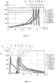
- In 2 and 3 are measurements of the torque curve when screwing ( Fig. 2 ) and unscrew ( Fig. 3 ) according to the threaded connection Fig. 4 shown depending on the revolutions.
- the revolutions are shown on the x-axis and the torque in Nm on the y-axis.
- the measurements of ten successive screwing or unscrewing operations are shown, the measured values being numbered 1 to 10 in accordance with the sequence of the screwing or unscrewing operations.
- FIG. 4 An embodiment of the invention is shown, the two pipe sections 1 and 2 being shown screwed together.
- the external thread 6 and the internal thread 7 are conical and have interacting first contact surfaces.
- the pipe sections 1, 2 each have interacting second contact surfaces, namely cooperating sealing surfaces 12 and 13 lying flat against one another and cooperating shoulder surfaces 14 and 15 lying flat against one another.
- Sealing surfaces 12, 13 are preferred conical educated.
- the shoulder surfaces 14, 15 usually run inclined to the axis 3, so that the two pipe sections 1 and 2 are pressed together when the screw connection is tightened on the shoulder surfaces 14, 15, but also on the sealing surfaces 12, 13.
Landscapes
- Engineering & Computer Science (AREA)
- General Engineering & Computer Science (AREA)
- Mechanical Engineering (AREA)
- Geology (AREA)
- Life Sciences & Earth Sciences (AREA)
- Mining & Mineral Resources (AREA)
- Fluid Mechanics (AREA)
- Environmental & Geological Engineering (AREA)
- General Life Sciences & Earth Sciences (AREA)
- Geochemistry & Mineralogy (AREA)
- Physics & Mathematics (AREA)
- Chemical & Material Sciences (AREA)
- Ceramic Engineering (AREA)
- Non-Disconnectible Joints And Screw-Threaded Joints (AREA)
- Lubricants (AREA)
- Paints Or Removers (AREA)
- Protection Of Pipes Against Damage, Friction, And Corrosion (AREA)
- Laminated Bodies (AREA)
- Dowels (AREA)
- Fishing Rods (AREA)
- Application Of Or Painting With Fluid Materials (AREA)
Description
- Die Erfindung betrifft eine Schraubverbindung umfassend ein mit einem Innengewinde versehenes rohrförmiges Element und ein mit einem Außengewinde versehenes rohrförmiges Element, wobei das Außengewinde und das Innengewinde miteinander zusammenwirkende erste Kontaktflächen aufweisen und die rohrförmigen Elemente vorzugsweise dem Innen- bzw. Außengewinde benachbarte zweite Kontaktflächen aufweisen, wobei die ersten Kontaktflächen und ggf. die zweiten Kontaktflächen jeweils mit einer Beschichtung versehen sind, die wenigstens eine erste und eine zweite Schicht umfasst, wobei die erste Schicht jeweils als Konversionsschicht ausgebildet ist.
- Die Erfindung betrifft weiters ein Verfahren zur Oberflächenbehandlung von Gewinden einer Gewindeverbindung von rohrförmigen Elementen umfassend das Aufbringen einer Beschichtung auf die miteinander zusammenwirkenden ersten Kontaktflächen eines Innengewindes und eines Außengewindes der Gewindeverbindung und vorzugsweise das Aufbringen einer Beschichtung auf dem Innen- bzw. Außengewinde benachbarte miteinander zusammenwirkende zweite Kontaktflächen der rohrförmigen Elemente, wobei die Beschichtung das Aufbringen wenigstens einer ersten Schicht und das Aufbringen einer zweiten Schicht auf der ersten Schicht umfasst, wobei als erste Schicht jeweils eine Konversionsschicht auf die Kontaktfläche aufgebracht wird.
- Insbesondere bezieht sich die Erfindung auf Schraubverbindungen, wie sie für die Verschraubung von Stahlrohren für die Erdöl- und Erdgasförderindustrie erforderlich sind. Es ist bekannt, dass die Gewindeverbindungen für die Erdöl- und Erdgasförderindustrie durch das Verschrauben und die Nutzbelastung sehr hohen Flächenpressungen ausgesetzt sind. Viele dieser Verbindungen müssen mehrfach verschraubt und wieder gelöst werden. Rohre für die Erdöl- und Erdgasförderindustrie (gemeinhin als OCTG-Rohre - Oil Country Tubular Goods - bezeichnet) werden insbesondere als Futter- und Steigrohre zur Erschließung von Erdöl- und Erdgaslagerstätten eingesetzt.
- An die Verschraubung der genannten Rohre werden hohe Anforderungen gestellt. Da die Gewinde auf Grund des hohen Anpressdrucks der miteinander zusammenwirkenden Gewindeflächen zum Fressen neigen, müssen Vorkehrungen getroffen werden, um ein Fressen und allgemein eine gegenseitige Beschädigung zu vermeiden. Weiters muss eine ausreichende Korrosionsbeständigkeit gegeben sein. Einschlägige Normen geben außerdem vor, dass die Gewindeverbindung zum mehrmaligen (bis zu 10 Mal) Verschrauben und Lösen der Verschraubung geeignet sein soll. Andere Normen im Bereich der Erdölbohrrohre fordern sogar eine 100 malige Wiederverschraubbarkeit.
- Im einfachsten Fall versucht man durch Auftragen von Gewindepaste die Beschädigung der Gewinde zu vermeiden. Allerdings ist die Notwendigkeit des Einfettens möglichst zu vermeiden, da der hierdurch verursachte Aufwand groß ist, insbesondere wenn im Zuge von mehrmaligen Verschraubungen ein Nachfetten erforderlich wird.
- Außerdem ist es bekannt, den Werkstoff der Gewindeflächen oberflächlich chemisch umzuwandeln oder ein fremdes Material aufzutragen, wodurch eine Konversionsschicht erhalten wird. Konversionsschichten werden in der Regel durch die chemische Reaktion einer wässrigen Behandlungslösung mit dem metallischen Untergrund erzeugt und bilden eine sehr gute Grundlage zur Anhaftung nachfolgender Beschichtungen und steigern signifikant die Korrosionsbeständigkeit des Grundmaterials im Vergleich zu unbehandelten Werkstoffoberflächen. Hierzu zählt das Phosphatieren der Gewindeflächen. Im Stand der Technik ist weiters die Oberflächenbeschichtung der Gewindeflächen mit den verschiedensten Stoffen beschrieben, welche die Verschraubungseigenschaften verbessern sollen. Ein Beispiel für derartige Beschichtungen zeigt
US-A1-2009/033087 . - Die bekannten Beschichtungen sind jedoch unzureichend, um sämtlichen Anforderungen in ausreichendem Maße gerecht zu werden.
- Die vorliegende Erfindung zielt daher darauf ab, eine Gewindeverbindung dahingehend zu verbessern, dass das Einfetten der Gewindeverbindung (insbesondere der Gewindegänge, des metallischen Dichtsitzes und der Schulterfläche) von Rohren auch beim mehrmaligen Verbinden der Rohrstücke vermieden werden kann. Die Fressneigung soll deutlich vermindert werden. Weiters soll die Anzahl der Mehrfachverschraubungen bei etwa gleichbleibendem Drehmomentverhalten für das Verschrauben und das Lösen erhöht werden, wobei die Dichtheit der Verschraubung sicher gestellt sein muss.
- Zur Lösung dieser Aufgabe besteht die Erfindung bei einer Gewindeverbindung der eingangs genannten Art im Wesentlichen darin, dass eine der miteinander zusammenwirkenden ersten und ggf. zweiten Kontaktflächen als zweite Schicht eine Schicht aus einem keramischen Material mit reibungsminderndem Effekt und die andere der miteinander zusammenwirkenden Kontaktflächen als zweite Schicht eine Lackschicht mit einem Bindemittel aus einem organischen Polymer trägt, in der feste Schmierstoffpartikel verteilt sind. Die beiden miteinander zusammenwirkenden Kontaktflächen tragen somit insgesamt jeweils mindestens zwei Schichten, wobei die im Rahmen der Erfindung als "zweite Schicht" bezeichnete Schicht bevorzugt jeweils die äußerste Schicht ist, an der das Außen- und das Innengewinde einander kontaktieren. Die zweite Schicht des Innengewindes ist aus einem anderen Material gebildet als die zweite Schicht des Außengewindes, nämlich aus einem keramischen Material mit reibungsminderndem Effekt einerseits und einem Lack mit einem Bindemittel aus einem organischen Polymer andererseits, wobei das Material jeweils so gewählt ist, dass sich die zweiten Schichten chemisch nicht miteinander verbinden, d.h. keine chemische Verbindung miteinander eingehen. Dadurch kann die Fressneigung drastisch gesenkt und die mehrmalige Lösbarkeit der Verbindung erreicht werden.
- Bevorzugt ist vorgesehen, dass die zweite Schicht aus keramischem Material an dem mit dem Innengewinde versehenen rohrförmigen Element und die als Lackschicht ausgeführte zweite Schicht an dem mit dem Außengewinde versehenen rohrförmigen Element ausgebildet ist.
- Die zweite Schicht aus dem keramischen Material erhöht den Korrosionsschutz an lackfreien Gewindeoberflächen deutlich. Weiters hat diese Schicht in Kombination mit der ersten Schicht, insbesondere wenn diese gemäß einer bevorzugten Ausbildung als Manganphosphatschicht ausgebildet ist, eine besonders reibungsmindernde Wirkung.
- Bevorzugt ist die erste Schicht als Phosphatschicht ausgebildet ist, wobei sie bevorzugt aus Manganphosphat, Eisenphosphat und/oder Zinkphosphat unter Zusatz von allenfalls Nickelsalzen, besonders bevorzugt aus Manganphosphat und Zinkphosphat und insbesondere bevorzugt aus Manganphosphat besteht.
- An der Kontaktfläche zwischen der aus keramischem Material bestehenden reibungsmindernden Schicht und der mit festen Schmierstoffpartikeln versehenen Lackschicht wird erfindungsgemäß eine sehr geringe Gleitreibung erzielt ohne dass ein Einfetten erforderlich ist. Die niedrige Gleitreibung wird hierbei über lange Zeit aufrechterhalten und ist insbesondere auch nach mehrmaligen Verschraubungen ohne wesentliche Verschlechterung der Gleiteigenschaften gewährleistet.
- Bevorzugt ist vorgesehen, dass die Schichtdicke der Lackschicht und der Anteil an Schmiermittel derart gewählt ist, dass diese bei Erdölförderrohren ohne Kaltverschweißung des Materials zumindest mehr als 10 mal und bei Erdölbohrrohren bevorzugt sogar mehr als 100 mal verschraubt und entschraubt werden können, ohne die Schmierwirkung der Lackschicht zu zerstören.
- Damit die Gewindegeometrie der beschichteten Gewinde im Vergleich zur unbeschichteten Ausführung unverändert bleibt, ist man bestrebt die Dicke der aufgebrachten Schichten möglichst gering zu halten. Eine bevorzugte Ausbildung sieht in diesem Zusammenhang vor, dass die Dicke der Beschichtung der miteinander zusammenwirkenden ersten Kontaktflächen weniger als 120 µm, bevorzugt weniger als 70 µm beträgt.
- Die keramische Schicht kann im Rahmen der Erfindung besonders dünn ausgebildet sein ohne ihre reibungsvermindernde und korrosionsschützende Eigenschaft zu beeinträchtigen. Insbesondere kann diese Schicht als Nanobeschichtung ausgebildet sein, wobei bevorzugt vorgesehen ist, dass die Schichtdicke der keramischen Schicht weniger als 1 µm, vorzugsweise weniger als 200 nm, insbesondere 10-100 nm beträgt.
- Ein solch dünner Auftrag gelingt vorzugsweise dadurch, dass die keramische Schicht aus einem nasschemischen, selbstabscheidenden Präzipitat oder aus einem lacktechnisch aufgebrachten Keramikpräpolymer mit organischen Anteilen besteht.
- Bevorzugt ist vorgesehen, dass die keramische Schicht ein Harz, wie z.B. Melaminharz, oder Hydrophobisierungsmittel enthält, insbesondere mit diesem imprägniert ist, um die Korrosionsfestigkeit zu erhöhen.
- Das Harz oder Hydrophobisierungsmittel zur Imprägnierung der Nanoschichten dient dem temporären Korrosionsschutz, verdichtet aber auch die poröse Nanoschicht langfristig und erhöht ihre Duktilität (somit werden die spröden Eigenschaften der Keramik gezielt reduziert).
- Um das Eindringen von Wasser zu vermeiden, können diverse Harze und technisch bekannte Hydrophobisierungsmittel aufgebracht werden. Als Harz können alle Harze mit ausreichender Stabilität dienen z.B. technisch gut charakterisierte Melaminharze oder Siloxane (z.B. auf PDMS-Basis). Diese müssen oft eingebrannt werden, um eine ausreichende Stabilität zu erhalten. Als Hydrophobisierungsmittel sind Alkoxysilane mit hydrophoben Seitengruppen oder deren Oligo- und Polymere bekannt, z.B. Dynasilane der Typen F8815 oder F8261.
- Die keramische Schicht umfasst vorzugweise Oxide von Titan, Zirkon, Niob, Tantal, Molybdän, Chrom, Silizium und/oder Germanium. Insbesondere besteht die keramische Schicht aus einem Oxid ausgewählt aus der Gruppe bestehend aus Oxiden von Titan, Zirkon, Niob, Tantal, Molybdän, Chrom, Silizium, Vanadium, Wolfram und Germanium und deren Gemischen. Besonders bevorzugt besteht die keramische Schicht aus Siliziumoxid, nämlich Quarz.
- Wie bereits erwähnt ist die erste Schicht bevorzugt eine durch Phosphatierung der Kontaktfläche erzeugte Schicht. Insbesondere handelt es sich hierbei um eine Manganphosphatschicht, wobei sowohl die am Außengewinde ausgebildete erste Schicht als auch die am Innengewinde ausgebildete erste Schicht durch Phosphatierung erzeugt, insbesondere als Manganphosphatschichten ausgebildet sind. Die Manganphosphatschicht wird vorzugsweise in einem heißen Badprozess erzeugt und kann alternativ galvanisch abgeschieden werden.
- Die Lackschicht dient einerseits der Erhöhung des Korrosionsschutzes und andererseits als Träger für die darin verteilten festen Schmierstoffpartikel. Die Schichtdicke der Lackschicht beträgt im Bereich der ersten Kontaktflächen bevorzugt 5-80 µm, besonders bevorzugt 10-40 µm, um die Gewindegeometrie nicht zu beeinträchtigen.
- Die erfindungsgemäße Beschichtung kann zusätzlich auch auf den dem Gewinde benachbarten, zweiten Kontaktflächen der beiden rohrförmigen Elemente aufgebracht sein. Dabei handelt es sich vorzugsweise um zur Ausbildung eines Dichtsitzes miteinander zusammenwirkende Dichtflächen und ggf. um miteinander zusammenwirkende Schulterflächen, wobei die Dichtflächen bevorzugt konisch ausgebildet sind und bevorzugt in Einschraubrichtung an das Innen- bzw. Außengewinde anschließend angeordnet sind. Die Dicke der Beschichtung, insbesondere der Lackschicht kann an den zweiten Dichtflächen größer gewählt sein als auf den Gewindeflächen, d.h. den ersten Kontaktflächen. Eine bevorzugte Ausbildung sieht hierbei vor, dass die Schichtdicke der Lackschicht im Bereich der zweiten Kontaktflächen 10-500 pm, bevorzugt 40-300 µm beträgt. Insbesondere kann vorgesehen sein, dass die Schichtdicke der Lackschicht im Bereich der Dichtflächen 10-300 µm, bevorzugt 40-150 µm beträgt. Im Bereich der Schulterflächen kann die Schichtdicke der Lackschicht 50-500 pm, bevorzugt 150-300 µm betragen.
- Hinsichtlich der Ausbildung der Gesamtschichtdicke sind folgende Ausführungsformen bevorzugt. Die Dicke der Beschichtung der miteinander zusammenwirkenden zweiten Kontaktflächen im Bereich der Dichtflächen kann weniger als 340 µm, bevorzugt weniger als 180 µm betragen. Die Dicke der Beschichtung der miteinander zusammenwirkenden zweiten Kontaktflächen im Bereich der Schulterflächen kann weniger als 540 µm, bevorzugt weniger als 330 µm betragen.
- Gemäß einer bevorzugten Weiterbildung der Erfindung ist das organische Polymer des Bindemittels der Lackschicht ein vernetzend-aushärtendes Polymer. Insbesondere besteht die Lackschicht aus einem Einbrennlack mit einem Kunstharz-Bindemittel oder umfasst als Bindemittel ein Zweikomponentensystem aus einem Kunstharz und einem Härter. Das Kunstharz ist bevorzugt ein Alkydharz, insbesondere ein epoxiharzmodifiziertes Alkydharz. Zum Beispiel kann ein SW Lack SILVATHERM 2312-3009-90 mit eingemischtem Wachs (Polypropylenwachs) eingesetzt werden.
- Die festen Schmierstoffpartikel sind bevorzugt polymerbasiert, insbesondere bestehen sie aus einem synthetischen Wachs, bevorzugt Polyolefin- oder Polyamid- oder Fluoropolymer-, insbesondere Polypropylenwachs. Der Anteil der festen Schmierstoffpartikel in der Lackschicht kann 1-50 Gew.-%, bevorzugt 1-20 Gew.-%, bevorzugter 1-10 Gew.-%, insbesondere 5 Gew.-% betragen. Eine solche Menge von Wachspartikeln setzt die Gleitreibung deutlich herab und erhöht das langzeitstabile Gleitverhalten.
- Bevorzugt ist vorgesehen, dass die erste und die zweite Schicht aus keramischem Material zusammen als Konversionsschicht, bevorzugt erzeugt über Phosphatierung, ausgebildet sind.
- Weiters ist bevorzugt vorgesehen, dass die Schmierstoffpartikel aus nicht kristallinen Fluorkohlenwasserstoffen bzw. nicht hochpolymeren, gegebenenfalls derivatisierten Kohlenwasserstoffen oder Silikonen bestehen.
- Bevorzugt ist vorgesehen, dass für den Einsatz bei Temperaturen unter dem Gefrierpunkt die Lackschicht geringer vernetzt ist.
- Gemäß einem weiteren Aspekt der Erfindung wird bei einem Verfahren der eingangs genannten Art so vorgegangen, dass auf eine der miteinander zusammenwirkenden Kontaktflächen als zweite Schicht eine Schicht aus einem keramischen Material mit reibungsminderndem Effekt und auf die andere der miteinander zusammenwirkenden Kontaktflächen als zweite Schicht eine Lackschicht mit einem Bindemittel aus einem organischen Polymer aufgebracht wird, in der feste Schmierstoffpartikel verteilt sind.
- Eine bevorzugte Verfahrensweise sieht vor, dass die Schicht aus keramischem Material als zweite Schicht auf die Kontaktfläche des Innengewindes und die Lackschicht als zweite Schicht auf die Kontaktfläche des Außengewindes aufgebracht wird.
- Eine weitere bevorzugte Verfahrensweise sieht vor, dass die keramische Schicht mit einer Schichtdicke von weniger als 1 µm, vorzugsweise weniger als 200 nm, insbesondere 10-100 nm aufgetragen wird. Insbesondere kann die keramische Schicht mit Vorteil durch nasschemische Ausfällung von Nanopartikeln, insbesondere SiO2-Nanopartikeln aus einer Lösung erzeugt werden. Die Lösung kann hierbei aus Ethyldiglykol oder Reaktionsethanol, Ammoniak und Tetraethylorthosilicat (TEOS) und Wasser bestehen.
- Dazu kann das rohrförmige Element mit im Wesentlichen senkrechter Rohrachse mit seinem Gewinde in ein Bad der Lösung getaucht werden, wobei bevorzugt das Niveau des Bads durch Anordnen eines Verdrängungskörpers im Inneren des rohrförmigen Elements erhöht wird. Alternativ kann so vorgegangen werden, dass das rohrförmige Element mit im Wesentlichen waagrechter Rohrachse mit einem umfangsmäßigen Abschnitt in ein Bad der Lösung getaucht und um die Rohrachse rotiert wird.
- Die Lackschicht kann bevorzugt durch Sprühen aufgebracht werden. Der Lack wird vorteilhaft mittels Sprühpistole aufgebracht und danach bei 130-180°C für 7-20 min ausgehärtet. Versuche haben gezeigt, dass Lackschichten unter 5 µm zu frühzeitigem Verreiben neigen, Lackschichten über 80 µm zeigen Momentanomalien bei Verschraubung. Günstige Lackschichtdicken, insbesondere solche für den Bereich der ersten Kontaktflächen, betragen 10-40 µm.
- Das mit einem Innengewinde versehene rohrförmige Element und das ein mit einem Außengewinde versehene rohrförmige Element können bspw. zwei Rohre oder ein Rohr und eine Muffe sein.
- Die Erfindung wird nachfolgend anhand eines in der Zeichnung schematisch dargestellten Ausführungsbeispiels näher erläutert. In dieser zeigen
Fig. 1 die einzelnen Beschichtungen des Innen- und des Außengewindes,Fig. 2 und 3 den Verlauf des beim Ver- und Entschrauben der Gewindeverbindung gemessenen Drehmoments als Funktion der Umdrehungen undFig. 4 einen Schnitt einer Schraubverbindung im zusammengeschraubten Zustand. - In
Fig. 1 ist ein mit einem Außengewinde 6 versehener Rohrabschnitt 1 und ein als Muffe mit einem Innengewinde 7 versehener Rohrabschnitt 2 dargestellt. Der Rohrabschnitt 1 weist eine Rohrachse 3 auf, wobei die Wand mit 4 bezeichnet ist. Die Wand des Rohrabschnitts 2 ist mit 5 bezeichnet. Das Außengewinde 6 und das Innengewinde 7 sind mit miteinander zusammenwirkenden Kontaktflächen ausgebildet, sodass der Rohrabschnitt 1 in den als Muffe ausgebildeten Rohrabschnitt 2 eingeschraubt werden kann, um eine Gewindeverbindung zwischen den beiden Rohrabschnitten herzustellen. - Auf der Kontaktfläche des Außengewindes 6 und der Kontaktfläche des Innengewindes 7 ist jeweils unmittelbar eine erste Schicht 8 bzw. 9 aufgebracht, die jeweils eine Manganphosphatschicht ist. Die Manganphosphatbeschichtungen 8 und 9 weisen eine Dicke von 5 bis 20 µm, bevorzugt 10-15 µm auf.
- Auf der Manganphosphatschicht 8 des Rohrabschnitts 1 ist eine Lackschicht 10 angeordnet, in welche Wachspartikel dispergiert sind. Die Lackschicht 10 ist bevorzugt mit einem Lack mit der Markenbezeichnung SILVATHERM 2312-3009-90 verwirklicht. Dabei handelt es sich um einen Einbrennlack auf Basis eines epoxidharzmodifizierten Alkydharzes. Bei den Wachspartikeln handelt es sich vorzugsweise um Partikel aus Polypropylenwachs, wobei ein Partikeldurchmesser von kleiner als 20 µm, insbesondere von 2-10 µm bevorzugt ist. Der Lack wird auf den metallischen Dichtsitz, die Schulterflächen und dem Außengewinde 10 aufgebracht und danach bei 130-180°C für ca. 7-20 min in einer Temperaturkammer ausgehärtet. Die Lackschicht weist eine Dicke von 5-80 µm, insbesondere 10-40 µm auf. Ein Einbrennlack auf Basis eines epoxidharzmodifizierten Alkydharzes zeigt auch bei tiefen Temperaturen von bis zu -40°C keine signifikante Verschlechterung der tribologischen Eigenschaften.
- Auf der Manganphosphatschicht 9 des Rohrabschnitts 2 ist eine Nanoquarzschicht 11 mit einer Schichtdicke von < 1 µm angeordnet.
- Versuche mit einer solchen Materialpaarung an den Kontaktflächen der Gewindeverbindung haben ergeben, dass eine konstante Reibzahl von ca. 0,06 über eine Prüfdauer von 400 Zyklen gegeben war.
- In
Fig. 2 und 3 sind Messungen des Drehmomentverlaufs beim Verschrauben (Fig. 2 ) und Entschrauben (Fig. 3 ) der Gewindeverbindung gemäßFig. 4 in Abhängigkeit von den Umdrehungen dargestellt. Auf der x-Achse sind jeweils die Umdrehungen dargestellt, auf der y-Achse das Drehmoment in Nm. Es sind die Messungen von zehn aufeinanderfolgenden Verschraubungs- bzw. Entschraubungsvorgängen eingezeichnet, wobei die Messwerte entsprechend der Reihenfolge der Verschraubungs- bzw. Entschraubungsvorgänge mit 1 bis 10 nummeriert sind. - Es ist ersichtlich, dass ohne Zusatzschmierung ein konstanter Drehmomentverlauf auch bei 10 aufeinanderfolgenden Verschraubungen gegeben ist.
- In
Fig. 4 ist eine Ausführungsform der Erfindung dargestellt, wobei die beiden Rohrabschnitte 1 und 2 in miteinander verschraubtem Zustand dargestellt sind. Das Außengewinde 6 und das Innengewinde 7 sind konisch ausgebildet und weisen zusammenwirkende erste Kontaktflächen auf. Im Anschluss an das Außen- und Innengewinde 6,7 weisen die Rohrabschnitte 1,2 jeweils miteinander zusammenwirkende zweite Kontaktflächen auf, nämlich flächig aneinander liegende zusammenwirkende Dichtflächen 12 und 13 sowie flächig aneinander liegende zusammenwirkende Schulterflächen 14 und 15. Die Dichtflächen 12,13 sind bevorzugt konisch ausgebildet. Die Schulterflächen 14,15 verlaufen zumeist geneigt zur Achse 3, sodass die beiden Rohrabschnitte 1 und 2 beim Festziehen der Schraubverbindung an den Schulterflächen 14,15, aber auch an den Dichtflächen 12,13 aneinandergepresst werden.
Claims (31)
- Schraubverbindung umfassend ein mit einem Innengewinde versehenes rohrförmiges Element und ein mit einem Außengewinde versehenes rohrförmiges Element, wobei das Außengewinde und das Innengewinde miteinander zusammenwirkende erste Kontaktflächen aufweisen und die rohrförmigen Elemente vorzugsweise dem Innen- bzw. Außengewinde benachbarte zweite Kontaktflächen aufweisen, wobei die ersten Kontaktflächen und ggf. die zweiten Kontaktflächen jeweils mit einer Beschichtung versehen sind, die wenigstens eine erste und eine zweite Schicht umfasst, wobei die erste Schicht jeweils als Konversionsschicht ausgebildet ist, dadurch gekennzeichnet, dass eine der miteinander zusammenwirkenden ersten und ggf. zweiten Kontaktflächen als zweite Schicht eine Schicht (11) aus einem keramischen Material mit reibungsminderndem Effekt und die andere der miteinander zusammenwirkenden Kontaktflächen als zweite Schicht eine Lackschicht (10) mit einem Bindemittel aus einem organischen Polymer trägt, in der feste Schmierstoffpartikel verteilt sind.
- Schraubverbindung nach Anspruch 1, dadurch gekennzeichnet, dass die zweite Schicht aus keramischem Material (11) an dem mit dem Innengewinde (7) versehenen rohrförmigen Element (2) ausgebildet ist und die als Lackschicht (10) ausgeführte zweite Schicht an dem mit dem Außengewinde (6) versehenen rohrförmigen Element (1) ausgebildet ist.
- Schraubverbindung nach Anspruch 1 oder 2, dadurch gekennzeichnet, dass die Schichtdicke der keramischen Schicht (11) weniger als 1 µm, vorzugsweise weniger als 200 nm, insbesondere 10-100 nm beträgt.
- Schraubverbindung nach Anspruch 1, 2 oder 3, dadurch gekennzeichnet, dass die keramische Schicht (11) ein Harz, wie z.B. Melaminharz, oder Hydrophobisierungsmittel enthält, insbesondere mit diesem imprägniert ist, um die Korrosionsfestigkeit zu erhöhen.
- Schraubverbindung nach einem der Ansprüche 1 bis 4, dadurch gekennzeichnet, dass die keramische Schicht (11) Oxide von Titan, Zirkon, Niob, Tantal, Molybdän, Chrom, Silizium, Vanadium, Wolfram, Germanium und/oder und deren Gemische umfasst.
- Schraubverbindung nach einem der Ansprüche 1 bis 5, dadurch gekennzeichnet, dass die keramische Schicht (11) aus einem nasschemischen, selbstabscheidenden Präzipitat oder aus einem lacktechnisch aufgebrachten Keramikpräpolymer mit organischen Anteilen besteht.
- Schraubverbindung nach einem der Ansprüche 1 bis 6, dadurch gekennzeichnet, dass die erste Schicht (8,9) als Phosphatschicht ausgebildet ist, wobei sie bevorzugt aus Manganphosphat, Eisenphosphat und/oder Zinkphosphat unter Zusatz von allenfalls Nickelsalzen, besonders bevorzugt aus Manganphosphat und Zinkphosphat und insbesondere bevorzugt aus Manganphosphat besteht.
- Schraubverbindung nach einem der Ansprüche 1 bis 7, dadurch gekennzeichnet, dass die zweiten Kontaktflächen zur Ausbildung eines Dichtsitzes miteinander zusammenwirkende Dichtflächen (12,13) und weiters miteinander zusammenwirkende Schulterflächen (14,15) umfassen, wobei die Dichtflächen (12,13) bevorzugt konisch ausgebildet sind und bevorzugt in Einschraubrichtung an das Innen- bzw. Außengewinde (7,6) anschließend angeordnet sind.
- Schraubverbindung nach einem der Ansprüche 1 bis 8, dadurch gekennzeichnet, dass die Schichtdicke der Lackschicht (10) im Bereich der ersten Kontaktflächen 5-80 µm, bevorzugt 10-40 µm beträgt.
- Schraubverbindung nach einem der Ansprüche 1 bis 9, dadurch gekennzeichnet, dass die Schichtdicke der Lackschicht (10) im Bereich der zweiten Kontaktflächen 10-500 µm, bevorzugt 40-300 µm beträgt.
- Schraubverbindung nach einem der Ansprüche 1 bis 10, dadurch gekennzeichnet, dass die Schichtdicke der Lackschicht (10) im Bereich der ersten Kontaktflächen geringer gewählt ist als im Bereich der zweiten Kontaktflächen.
- Schraubverbindung nach einem der Ansprüche 8 bis 11, dadurch gekennzeichnet, dass die Schichtdicke der Lackschicht (10) im Bereich der Dichtflächen (12,13) 10-300 µm, bevorzugt 40-150 µm beträgt.
- Schraubverbindung nach einem der Ansprüche 8 bis 12, dadurch gekennzeichnet, dass die Schichtdicke der Lackschicht (10) im Bereich der Schulterflächen (14,15) 50-500 µm, bevorzugt 150-300 µm beträgt.
- Schraubverbindung nach einem der Ansprüche 1 bis 13, dadurch gekennzeichnet, dass das organische Polymer des Bindemittels der Lackschicht ein vernetzend-aushärtendes Polymer ist.
- Schraubverbindung nach einem der Ansprüche 1 bis 14, dadurch gekennzeichnet, dass die Lackschicht (10) aus einem Einbrennlack mit einem Kunstharz-Bindemittel besteht oder als Bindemittel ein Zweikomponentensystem aus einem Kunstharz und einem Härter umfasst.
- Schraubverbindung nach Anspruch 15, dadurch gekennzeichnet, dass das Kunstharz ein Alkydharz, insbesondere ein epoxiharzmodifiziertes Alkydharz ist.
- Schraubverbindung nach einem der Ansprüche 1 bis 16, dadurch gekennzeichnet, dass die festen Schmierstoffpartikel polymerbasiert sind, insbesondere aus einem synthetischen Wachs, bevorzugt Polyolefin-, oder Polyamid- oder Fluoropolymer, insbesondere Polypropylenwachs bestehen.
- Schraubverbindung nach einem der Ansprüche 1 bis 17, dadurch gekennzeichnet, dass der Anteil der festen Schmierstoffpartikel in der Lackschicht (10) 1-50 Gew.-%, bevorzugt 1-20 Gew.-%, bevorzugter 1-10 Gew.-%, insbesondere 5 Gew.-% beträgt.
- Schraubverbindung nach einem der Ansprüche 1 bis 18, dadurch gekennzeichnet, dass die Dicke der Beschichtung der miteinander zusammenwirkenden ersten Kontaktflächen weniger als 120 µm, bevorzugt weniger als 70 µm beträgt.
- Schraubverbindung nach einem der Ansprüche 8 bis 19, dadurch gekennzeichnet, dass die Dicke der Beschichtung der miteinander zusammenwirkenden zweiten Kontaktflächen im Bereich der Dichtflächen (12,13) weniger als 340 µm, bevorzugt weniger als 180 µm beträgt.
- Schraubverbindung nach einem der Ansprüche 8 bis 20, dadurch gekennzeichnet, dass die Dicke der Beschichtung der miteinander zusammenwirkenden zweiten Kontaktflächen im Bereich der Schulterflächen (14,15) weniger als 540 µm, bevorzugt weniger als 330 µm beträgt.
- Schraubverbindung nach einem der Ansprüche 1 bis 21, dadurch gekennzeichnet, dass die erste und die zweite Schicht aus keramischem Material zusammen als Konversionsschicht, bevorzugt erzeugt über Phosphatierung, ausgebildet sind.
- Schraubverbindung nach einem der Ansprüche 1 bis 22, dadurch gekennzeichnet, dass die Schmierstoffpartikel aus nicht kristallinen Fluorkohlenwasserstoffen bzw. nicht hochpolymeren, gegebenenfalls derivatisierten Kohlenwasserstoffen oder Silikonen bestehen.
- Verfahren zur Oberflächenbehandlung von Gewinden einer Gewindeverbindung von rohrförmigen Elementen umfassend das Aufbringen einer Beschichtung auf die miteinander zusammenwirkenden ersten Kontaktflächen eines Innengewindes und eines Außengewindes der Gewindeverbindung und vorzugsweise das Aufbringen einer Beschichtung auf dem Innen- bzw. Außengewinde benachbarte, miteinander zusammenwirkende zweite Kontaktflächen der rohrförmigen Elemente, wobei die Beschichtung das Aufbringen wenigstens einer ersten Schicht und das Aufbringen einer zweiten Schicht auf der ersten Schicht umfasst, wobei als erste Schicht jeweils eine Konversionsschicht auf die Kontaktfläche aufgebracht wird, dadurch gekennzeichnet, dass auf eine der miteinander zusammenwirkenden ersten und ggf. zweiten Kontaktflächen als zweite Schicht eine Schicht (11) aus einem keramischen Material mit reibungsminderndem Effekt und auf die andere der miteinander zusammenwirkenden Kontaktflächen als zweite Schicht eine Lackschicht (10) mit einem Bindemittel aus einem organischen Polymer aufgebracht wird, in der feste Schmierstoffpartikel verteilt sind.
- Verfahren nach Anspruch 24, dadurch gekennzeichnet, dass die Schicht (11) aus keramischem Material als zweite Schicht auf die Kontaktfläche des Innengewindes (7) und die Lackschicht (10) als zweite Schicht auf die Kontaktfläche des Außengewindes (6) aufgebracht wird.
- Verfahren nach Anspruch 24 oder 25, dadurch gekennzeichnet, dass die keramische Schicht (11) mit einer Schichtdicke von weniger als 1 µm, vorzugsweise weniger als 200 nm, insbesondere 10-100 nm aufgetragen wird.
- Verfahren nach Anspruch 24, 25 oder 26, dadurch gekennzeichnet, dass die keramische Schicht (11) durch nasschemische Ausfällung von Nanopartikeln, insbesondere SiO2-Nanopartikeln aus einer Lösung erzeugt wird.
- Verfahren nach Anspruch 27, dadurch gekennzeichnet, dass das rohrförmige Element (2) mit im Wesentlichen senkrechter Rohrachse mit seinem Gewinde (7) in ein Bad der Lösung getaucht wird, wobei bevorzugt das Niveau des Bads durch Anordnen eines Verdrängungskörpers im Inneren des rohrförmigen Elements erhöht wird.
- Verfahren nach Anspruch 27, dadurch gekennzeichnet, dass das rohrförmige Element (2) mit im Wesentlichen waagrechter Rohrachse mit einem umfangsmäßigen Abschnitt in ein Bad der Lösung getaucht und um die Rohrachse rotiert wird.
- Verfahren nach einem der Ansprüche 24 bis 29, dadurch gekennzeichnet, dass die Lackschicht (10) im Bereich der ersten Kontaktflächen mit einer Schichtdicke von 5-80 µm, bevorzugt 10-40 µm aufgetragen wird.
- Verfahren nach einem der Ansprüche 24 bis 30, dadurch gekennzeichnet, dass die Lackschicht (10) durch Sprühen aufgebracht wird.
Priority Applications (4)
| Application Number | Priority Date | Filing Date | Title |
|---|---|---|---|
| RS20200289A RS60060B1 (sr) | 2015-01-13 | 2015-12-29 | Rastavljiva navojna veza sa asimetričnom prevlakom |
| SI201531195T SI3245378T1 (sl) | 2015-01-13 | 2015-12-29 | Ločljiva navojna povezava z asimetrično prevleko |
| HRP20200443TT HRP20200443T1 (hr) | 2015-01-13 | 2015-12-29 | Odvojivi navojni spoj s asimetričnom oblogom |
| PL15820024T PL3245378T3 (pl) | 2015-01-13 | 2015-12-29 | Rozłączne połączenie gwintowe z asymetryczną powłoką |
Applications Claiming Priority (2)
| Application Number | Priority Date | Filing Date | Title |
|---|---|---|---|
| ATA16/2015A AT516684B1 (de) | 2015-01-13 | 2015-01-13 | Lösbare Gewindeverbindung mit asymmetrischer Beschichtung |
| PCT/AT2015/000165 WO2016112415A1 (de) | 2015-01-13 | 2015-12-29 | Lösbare gewindeverbindung mit asymmetrischer beschichtung |
Publications (2)
| Publication Number | Publication Date |
|---|---|
| EP3245378A1 EP3245378A1 (de) | 2017-11-22 |
| EP3245378B1 true EP3245378B1 (de) | 2020-02-05 |
Family
ID=55069637
Family Applications (1)
| Application Number | Title | Priority Date | Filing Date |
|---|---|---|---|
| EP15820024.6A Active EP3245378B1 (de) | 2015-01-13 | 2015-12-29 | Lösbare gewindeverbindung mit asymmetrischer beschichtung |
Country Status (22)
| Country | Link |
|---|---|
| US (1) | US11105457B2 (de) |
| EP (1) | EP3245378B1 (de) |
| JP (1) | JP6531176B2 (de) |
| CN (1) | CN107208462B (de) |
| AT (1) | AT516684B1 (de) |
| AU (1) | AU2015376846B2 (de) |
| CA (1) | CA2973476C (de) |
| EA (1) | EA033700B1 (de) |
| ES (1) | ES2786176T3 (de) |
| HR (1) | HRP20200443T1 (de) |
| HU (1) | HUE049512T2 (de) |
| IL (1) | IL253270B (de) |
| MX (1) | MX386077B (de) |
| MY (1) | MY184927A (de) |
| PL (1) | PL3245378T3 (de) |
| RS (1) | RS60060B1 (de) |
| SG (1) | SG11201705341TA (de) |
| SI (1) | SI3245378T1 (de) |
| TN (1) | TN2017000279A1 (de) |
| UA (1) | UA120956C2 (de) |
| WO (1) | WO2016112415A1 (de) |
| ZA (1) | ZA201704603B (de) |
Families Citing this family (1)
| Publication number | Priority date | Publication date | Assignee | Title |
|---|---|---|---|---|
| WO2023153274A1 (ja) * | 2022-02-10 | 2023-08-17 | 日本製鉄株式会社 | 油井用金属管 |
Family Cites Families (33)
| Publication number | Priority date | Publication date | Assignee | Title |
|---|---|---|---|---|
| US4468309A (en) * | 1983-04-22 | 1984-08-28 | White Engineering Corporation | Method for resisting galling |
| JPS60205091A (ja) * | 1984-03-29 | 1985-10-16 | 住友金属工業株式会社 | 油井管用管継手 |
| JPH01199088A (ja) * | 1988-02-03 | 1989-08-10 | Nippon Steel Corp | 耐隙間腐食性に優れた高合金油井管用継手 |
| JPH0694036A (ja) | 1992-09-11 | 1994-04-05 | Daido Metal Co Ltd | 耐フレッチング特性に優れた多層すべり軸受 |
| JPH06109173A (ja) * | 1992-09-28 | 1994-04-19 | Nippon Steel Corp | 油井管継手 |
| US5454605A (en) | 1993-06-15 | 1995-10-03 | Hydril Company | Tool joint connection with interlocking wedge threads |
| US5494566A (en) | 1994-05-26 | 1996-02-27 | Mobil Oil Corporation | Lubricating oil dewaxing with membrane separation of cold solvent |
| JP3775122B2 (ja) * | 1999-08-27 | 2006-05-17 | 住友金属工業株式会社 | 油井管用ねじ継手 |
| EP1211451B1 (de) * | 1999-08-27 | 2011-10-05 | Sumitomo Metal Industries, Ltd. | Schraubverbindung für ölfeldrohre |
| EP1892449B1 (de) | 2001-04-11 | 2010-12-29 | Sumitomo Metal Industries, Ltd. | Schraubverbindung für Stahlrohre |
| JP3870732B2 (ja) * | 2001-07-25 | 2007-01-24 | 住友金属工業株式会社 | 耐焼付き性に優れた鋼管用ねじ継手 |
| JP4680446B2 (ja) * | 2001-08-31 | 2011-05-11 | Jfeスチール株式会社 | 油井鋼管用継手 |
| US20050176592A1 (en) * | 2004-02-11 | 2005-08-11 | Tenaris Ag | Method of using intrinsically conductive polymers with inherent lubricating properties, and a composition having an intrinsically conductive polymer, for protecting metal surfaces from galling and corrosion |
| WO2006075774A1 (en) * | 2005-01-13 | 2006-07-20 | Sumitomo Metal Industries, Ltd. | Threaded joint for steel pipes |
| WO2006104251A1 (en) | 2005-03-29 | 2006-10-05 | Sumitomo Metal Industries, Ltd. | Threaded joint for steel pipes |
| AR057940A1 (es) * | 2005-11-30 | 2007-12-26 | Tenaris Connections Ag | Conexiones roscadas con recubrimientos de alta y baja friccion |
| US20080038083A1 (en) * | 2006-07-17 | 2008-02-14 | General Electric Company | Fasteners Coated with Boron Nitride and Means for Securing Fasteners |
| JP5028923B2 (ja) | 2006-09-14 | 2012-09-19 | 住友金属工業株式会社 | 鋼管用ねじ継手 |
| JP4924103B2 (ja) | 2007-03-02 | 2012-04-25 | 住友金属工業株式会社 | 油井管用ねじ継手 |
| FR2914926B1 (fr) * | 2007-04-11 | 2013-11-01 | Vallourec Mannesmann Oil & Gas | Composition de lubrification a coefficient de frottement adaptable, pour un element filete d'un composant de joint filete tubulaire. |
| BRPI0820002B1 (pt) * | 2007-12-04 | 2019-01-22 | Nippon Steel & Sumitomo Metal Corp | junta rosqueada para tubos |
| US8561707B2 (en) * | 2009-08-18 | 2013-10-22 | Exxonmobil Research And Engineering Company | Ultra-low friction coatings for drill stem assemblies |
| US20110084477A1 (en) * | 2009-10-13 | 2011-04-14 | Hydril Company | Wedge threads with a solid lubricant coating |
| BR112013001505B1 (pt) * | 2010-07-20 | 2019-03-19 | Tenaris Connections B.V. | Método de montagem de uma junta e junta |
| UA104975C2 (uk) | 2010-11-05 | 2014-03-25 | Ніппон Стіл Енд Сумітомо Метал Корпорейшн | Нарізне з'єднання труб, що має поліпшені характеристики при низькій температурі |
| FR2970028B1 (fr) * | 2010-12-29 | 2012-12-28 | Vallourec Mannesmann Oil & Gas | Procede de revetement d'un composant tubulaire filete, composant filete et joint resultant |
| FR2981395B1 (fr) * | 2011-10-14 | 2016-04-01 | Vallourec Mannesmann Oil & Gas | Composant filete tubulaire et joint resultant |
| JP5722752B2 (ja) * | 2011-11-18 | 2015-05-27 | 新日鐵住金株式会社 | 高トルク締結性能に優れた管状ねじ継手 |
| DE102012108433C9 (de) * | 2012-09-10 | 2022-11-24 | Cooper-Standard Automotive (Deutschland) Gmbh | Rohrschraube zur Befestigung einer Rohrleitung und ein Verfahren zur Herstellung einer solchen Rohrschraube |
| MY169937A (en) * | 2012-09-12 | 2019-06-18 | Nippon Steel Corp | Composition for solid coating formation and tubular threaded joint |
| DE102012023349B4 (de) * | 2012-11-29 | 2022-10-13 | Hochschule München | Verfahren und Vorrichtung zur strukturierten Beschichtung der Innenseite eines Schlauchs oder Rohrs |
| FR3000168B1 (fr) | 2012-12-21 | 2015-01-02 | Vallourec Mannesmann Oil & Gas | Ensemble pour la realisation d'un joint filete tubulaire resistant au grippage |
| CN203939451U (zh) * | 2013-10-11 | 2014-11-12 | 杨林 | 镍基合金油管或套管 |
-
2015
- 2015-01-13 AT ATA16/2015A patent/AT516684B1/de active
- 2015-12-29 RS RS20200289A patent/RS60060B1/sr unknown
- 2015-12-29 US US15/542,683 patent/US11105457B2/en active Active
- 2015-12-29 WO PCT/AT2015/000165 patent/WO2016112415A1/de not_active Ceased
- 2015-12-29 CN CN201580073303.9A patent/CN107208462B/zh active Active
- 2015-12-29 ES ES15820024T patent/ES2786176T3/es active Active
- 2015-12-29 JP JP2017537304A patent/JP6531176B2/ja active Active
- 2015-12-29 TN TNP/2017/000279A patent/TN2017000279A1/en unknown
- 2015-12-29 MX MX2017009084A patent/MX386077B/es unknown
- 2015-12-29 UA UAA201708317A patent/UA120956C2/uk unknown
- 2015-12-29 HR HRP20200443TT patent/HRP20200443T1/hr unknown
- 2015-12-29 AU AU2015376846A patent/AU2015376846B2/en active Active
- 2015-12-29 HU HUE15820024A patent/HUE049512T2/hu unknown
- 2015-12-29 MY MYPI2017702436A patent/MY184927A/en unknown
- 2015-12-29 EA EA201791583A patent/EA033700B1/ru not_active IP Right Cessation
- 2015-12-29 SI SI201531195T patent/SI3245378T1/sl unknown
- 2015-12-29 CA CA2973476A patent/CA2973476C/en active Active
- 2015-12-29 EP EP15820024.6A patent/EP3245378B1/de active Active
- 2015-12-29 SG SG11201705341TA patent/SG11201705341TA/en unknown
- 2015-12-29 PL PL15820024T patent/PL3245378T3/pl unknown
-
2017
- 2017-07-02 IL IL253270A patent/IL253270B/en active IP Right Grant
- 2017-07-07 ZA ZA2017/04603A patent/ZA201704603B/en unknown
Also Published As
| Publication number | Publication date |
|---|---|
| JP6531176B2 (ja) | 2019-06-12 |
| HRP20200443T1 (hr) | 2020-06-12 |
| CA2973476C (en) | 2021-05-25 |
| ES2786176T3 (es) | 2020-10-09 |
| HUE049512T2 (hu) | 2020-09-28 |
| US11105457B2 (en) | 2021-08-31 |
| MX2017009084A (es) | 2018-03-01 |
| WO2016112415A1 (de) | 2016-07-21 |
| AU2015376846B2 (en) | 2020-04-02 |
| RS60060B1 (sr) | 2020-04-30 |
| AT516684A1 (de) | 2016-07-15 |
| TN2017000279A1 (en) | 2019-01-16 |
| EP3245378A1 (de) | 2017-11-22 |
| AU2015376846A1 (en) | 2017-08-10 |
| ZA201704603B (en) | 2019-06-26 |
| SG11201705341TA (en) | 2017-07-28 |
| MY184927A (en) | 2021-04-30 |
| EA033700B1 (ru) | 2019-11-18 |
| NZ733578A (en) | 2021-05-28 |
| IL253270B (en) | 2021-06-30 |
| AT516684B1 (de) | 2018-08-15 |
| EA201791583A1 (ru) | 2018-03-30 |
| MX386077B (es) | 2025-03-18 |
| IL253270A0 (en) | 2017-08-31 |
| PL3245378T3 (pl) | 2020-09-07 |
| CN107208462B (zh) | 2019-10-11 |
| SI3245378T1 (sl) | 2020-07-31 |
| US20180031170A1 (en) | 2018-02-01 |
| JP2018508719A (ja) | 2018-03-29 |
| CA2973476A1 (en) | 2016-07-21 |
| UA120956C2 (uk) | 2020-03-10 |
| CN107208462A (zh) | 2017-09-26 |
Similar Documents
| Publication | Publication Date | Title |
|---|---|---|
| EP2952796B1 (de) | Schraubelement für den anschluss von rohrleitungen und rohranschlusseinrichtung mit diesem schraubelement | |
| DE102009010110B4 (de) | Erosionsschutz-Beschichtungssystem für Gasturbinenbauteile | |
| DE3021628A1 (de) | Korrosionsbestaendiges waermetauscherbauteil und verfahren zu seiner herstellung | |
| WO2013017638A1 (de) | Stossdämpfer für ein fahrzeug in leichtbauweise | |
| WO2016131700A1 (de) | Fitting mit beschichtung, rohrleitungssystem und verwendung des fittings oder des rohrleitungssystems | |
| EP2884145A1 (de) | Element einer Schellen-Flansch-Verbindung | |
| EP3485173A1 (de) | Spreizdübel mit zinklegierungs-beschichtung | |
| WO2015135745A1 (de) | Korrosionsschützendes schichtsystem, korrosionsgeschütztes lagerbauteil und verfahren zum schutz eines lagerbauteils vor korrosion | |
| DE2818184C3 (de) | Verfahren zur Herstellung eines Schichtwerkstoffs mit reibungsarmer Oberfläche für geformte Werkstücke | |
| EP1455101A1 (de) | Schraube und Verfahren zur Herstellung einer Schutzschicht auf einer Schraube | |
| EP3594969B1 (de) | Verfahren zur herstellung eines mit elektroisolierlack beschichteten leiterdrahtes und elektroisolierlack | |
| WO2020002542A2 (de) | Tragevorrichtung zur aufnahme eines rohrleitungselements, betreffendes transportsystem sowie herstellungsverfahren | |
| WO2009015647A2 (de) | Verfahren zum herstellen einer gleitschicht auf einer gleitlagerkomponente sowie gleitlagerkomponente | |
| AT516684B1 (de) | Lösbare Gewindeverbindung mit asymmetrischer Beschichtung | |
| AT513361A1 (de) | Transport- oder Prozessband | |
| EP3961078B1 (de) | Verfahren zur beschichtung eines schraubelementes, schraubelement und rohranschlusseinrichtung | |
| EP3000977B1 (de) | Schaufel einer turbine mit wasserabweisendem beschichtetem schaufelblatt | |
| EP3746689B1 (de) | Leitungselement mit reibmindernder schicht | |
| DE102008048020A1 (de) | Gleitlager | |
| EP3961077B1 (de) | Verfahren zur behandlung einer rohrleitung, rohrleitung und rohranschlusseinrichtung | |
| DE10311142B4 (de) | Lacksystem als Oberflächenschicht für Substrate und Verfahren zum Herstellen des Lacksystems | |
| DE102009053487B4 (de) | Verfahren zur Herstellung einer pneumatischen Zentralausrückeranordnung | |
| EP3325831B1 (de) | Lagerring für ein lagerelement und verfahren zur herstellung eines lagerrings | |
| WO2006087072A1 (de) | Gelenkzapfen für ein kugelgelenk und verfahren zum herstellen eines solchen | |
| DE29501626U1 (de) | Schwebekörper-Durchflußmesser |
Legal Events
| Date | Code | Title | Description |
|---|---|---|---|
| STAA | Information on the status of an ep patent application or granted ep patent |
Free format text: STATUS: THE INTERNATIONAL PUBLICATION HAS BEEN MADE |
|
| PUAI | Public reference made under article 153(3) epc to a published international application that has entered the european phase |
Free format text: ORIGINAL CODE: 0009012 |
|
| STAA | Information on the status of an ep patent application or granted ep patent |
Free format text: STATUS: REQUEST FOR EXAMINATION WAS MADE |
|
| 17P | Request for examination filed |
Effective date: 20170622 |
|
| AK | Designated contracting states |
Kind code of ref document: A1 Designated state(s): AL AT BE BG CH CY CZ DE DK EE ES FI FR GB GR HR HU IE IS IT LI LT LU LV MC MK MT NL NO PL PT RO RS SE SI SK SM TR |
|
| AX | Request for extension of the european patent |
Extension state: BA ME |
|
| RAP1 | Party data changed (applicant data changed or rights of an application transferred) |
Owner name: VOESTALPINE TUBULARS GMBH & CO KG |
|
| DAX | Request for extension of the european patent (deleted) | ||
| RAV | Requested validation state of the european patent: fee paid |
Extension state: MA Effective date: 20170622 |
|
| GRAP | Despatch of communication of intention to grant a patent |
Free format text: ORIGINAL CODE: EPIDOSNIGR1 |
|
| STAA | Information on the status of an ep patent application or granted ep patent |
Free format text: STATUS: GRANT OF PATENT IS INTENDED |
|
| INTG | Intention to grant announced |
Effective date: 20190910 |
|
| GRAS | Grant fee paid |
Free format text: ORIGINAL CODE: EPIDOSNIGR3 |
|
| GRAA | (expected) grant |
Free format text: ORIGINAL CODE: 0009210 |
|
| STAA | Information on the status of an ep patent application or granted ep patent |
Free format text: STATUS: THE PATENT HAS BEEN GRANTED |
|
| AK | Designated contracting states |
Kind code of ref document: B1 Designated state(s): AL AT BE BG CH CY CZ DE DK EE ES FI FR GB GR HR HU IE IS IT LI LT LU LV MC MK MT NL NO PL PT RO RS SE SI SK SM TR |
|
| REG | Reference to a national code |
Ref country code: GB Ref legal event code: FG4D Free format text: NOT ENGLISH |
|
| REG | Reference to a national code |
Ref country code: AT Ref legal event code: REF Ref document number: 1230014 Country of ref document: AT Kind code of ref document: T Effective date: 20200215 |
|
| REG | Reference to a national code |
Ref country code: DE Ref legal event code: R096 Ref document number: 502015011656 Country of ref document: DE |
|
| REG | Reference to a national code |
Ref country code: IE Ref legal event code: FG4D Free format text: LANGUAGE OF EP DOCUMENT: GERMAN |
|
| REG | Reference to a national code |
Ref country code: HR Ref legal event code: TUEP Ref document number: P20200443 Country of ref document: HR |
|
| REG | Reference to a national code |
Ref country code: CH Ref legal event code: EP |
|
| REG | Reference to a national code |
Ref country code: SE Ref legal event code: TRGR |
|
| REG | Reference to a national code |
Ref country code: NL Ref legal event code: FP |
|
| REG | Reference to a national code |
Ref country code: RO Ref legal event code: EPE |
|
| REG | Reference to a national code |
Ref country code: SK Ref legal event code: T3 Ref document number: E 33741 Country of ref document: SK |
|
| REG | Reference to a national code |
Ref country code: NO Ref legal event code: T2 Effective date: 20200205 |
|
| REG | Reference to a national code |
Ref country code: HR Ref legal event code: T1PR Ref document number: P20200443 Country of ref document: HR |
|
| PG25 | Lapsed in a contracting state [announced via postgrant information from national office to epo] |
Ref country code: PT Free format text: LAPSE BECAUSE OF FAILURE TO SUBMIT A TRANSLATION OF THE DESCRIPTION OR TO PAY THE FEE WITHIN THE PRESCRIBED TIME-LIMIT Effective date: 20200628 Ref country code: FI Free format text: LAPSE BECAUSE OF FAILURE TO SUBMIT A TRANSLATION OF THE DESCRIPTION OR TO PAY THE FEE WITHIN THE PRESCRIBED TIME-LIMIT Effective date: 20200205 |
|
| REG | Reference to a national code |
Ref country code: LT Ref legal event code: MG4D |
|
| PG25 | Lapsed in a contracting state [announced via postgrant information from national office to epo] |
Ref country code: GR Free format text: LAPSE BECAUSE OF FAILURE TO SUBMIT A TRANSLATION OF THE DESCRIPTION OR TO PAY THE FEE WITHIN THE PRESCRIBED TIME-LIMIT Effective date: 20200506 Ref country code: LV Free format text: LAPSE BECAUSE OF FAILURE TO SUBMIT A TRANSLATION OF THE DESCRIPTION OR TO PAY THE FEE WITHIN THE PRESCRIBED TIME-LIMIT Effective date: 20200205 Ref country code: IS Free format text: LAPSE BECAUSE OF FAILURE TO SUBMIT A TRANSLATION OF THE DESCRIPTION OR TO PAY THE FEE WITHIN THE PRESCRIBED TIME-LIMIT Effective date: 20200605 |
|
| REG | Reference to a national code |
Ref country code: HU Ref legal event code: AG4A Ref document number: E049512 Country of ref document: HU |
|
| REG | Reference to a national code |
Ref country code: ES Ref legal event code: FG2A Ref document number: 2786176 Country of ref document: ES Kind code of ref document: T3 Effective date: 20201009 |
|
| PG25 | Lapsed in a contracting state [announced via postgrant information from national office to epo] |
Ref country code: LT Free format text: LAPSE BECAUSE OF FAILURE TO SUBMIT A TRANSLATION OF THE DESCRIPTION OR TO PAY THE FEE WITHIN THE PRESCRIBED TIME-LIMIT Effective date: 20200205 Ref country code: EE Free format text: LAPSE BECAUSE OF FAILURE TO SUBMIT A TRANSLATION OF THE DESCRIPTION OR TO PAY THE FEE WITHIN THE PRESCRIBED TIME-LIMIT Effective date: 20200205 Ref country code: SM Free format text: LAPSE BECAUSE OF FAILURE TO SUBMIT A TRANSLATION OF THE DESCRIPTION OR TO PAY THE FEE WITHIN THE PRESCRIBED TIME-LIMIT Effective date: 20200205 Ref country code: DK Free format text: LAPSE BECAUSE OF FAILURE TO SUBMIT A TRANSLATION OF THE DESCRIPTION OR TO PAY THE FEE WITHIN THE PRESCRIBED TIME-LIMIT Effective date: 20200205 |
|
| REG | Reference to a national code |
Ref country code: DE Ref legal event code: R097 Ref document number: 502015011656 Country of ref document: DE |
|
| PLBE | No opposition filed within time limit |
Free format text: ORIGINAL CODE: 0009261 |
|
| STAA | Information on the status of an ep patent application or granted ep patent |
Free format text: STATUS: NO OPPOSITION FILED WITHIN TIME LIMIT |
|
| REG | Reference to a national code |
Ref country code: HR Ref legal event code: ODRP Ref document number: P20200443 Country of ref document: HR Payment date: 20201204 Year of fee payment: 6 |
|
| 26N | No opposition filed |
Effective date: 20201106 |
|
| VS25 | Lapsed in a validation state [announced via postgrant information from nat. office to epo] |
Ref country code: MA Free format text: LAPSE BECAUSE OF FAILURE TO SUBMIT A TRANSLATION OF THE DESCRIPTION OR TO PAY THE FEE WITHIN THE PRESCRIBED TIME-LIMIT Effective date: 20200205 |
|
| REG | Reference to a national code |
Ref country code: CH Ref legal event code: PL |
|
| PG25 | Lapsed in a contracting state [announced via postgrant information from national office to epo] |
Ref country code: MC Free format text: LAPSE BECAUSE OF FAILURE TO SUBMIT A TRANSLATION OF THE DESCRIPTION OR TO PAY THE FEE WITHIN THE PRESCRIBED TIME-LIMIT Effective date: 20200205 |
|
| REG | Reference to a national code |
Ref country code: BE Ref legal event code: MM Effective date: 20201231 |
|
| PG25 | Lapsed in a contracting state [announced via postgrant information from national office to epo] |
Ref country code: IE Free format text: LAPSE BECAUSE OF NON-PAYMENT OF DUE FEES Effective date: 20201229 |
|
| PG25 | Lapsed in a contracting state [announced via postgrant information from national office to epo] |
Ref country code: LI Free format text: LAPSE BECAUSE OF NON-PAYMENT OF DUE FEES Effective date: 20201231 Ref country code: CH Free format text: LAPSE BECAUSE OF NON-PAYMENT OF DUE FEES Effective date: 20201231 |
|
| REG | Reference to a national code |
Ref country code: HR Ref legal event code: ODRP Ref document number: P20200443 Country of ref document: HR Payment date: 20211203 Year of fee payment: 7 |
|
| PG25 | Lapsed in a contracting state [announced via postgrant information from national office to epo] |
Ref country code: MT Free format text: LAPSE BECAUSE OF FAILURE TO SUBMIT A TRANSLATION OF THE DESCRIPTION OR TO PAY THE FEE WITHIN THE PRESCRIBED TIME-LIMIT Effective date: 20200205 Ref country code: CY Free format text: LAPSE BECAUSE OF FAILURE TO SUBMIT A TRANSLATION OF THE DESCRIPTION OR TO PAY THE FEE WITHIN THE PRESCRIBED TIME-LIMIT Effective date: 20200205 |
|
| PG25 | Lapsed in a contracting state [announced via postgrant information from national office to epo] |
Ref country code: AL Free format text: LAPSE BECAUSE OF FAILURE TO SUBMIT A TRANSLATION OF THE DESCRIPTION OR TO PAY THE FEE WITHIN THE PRESCRIBED TIME-LIMIT Effective date: 20200205 |
|
| PG25 | Lapsed in a contracting state [announced via postgrant information from national office to epo] |
Ref country code: BE Free format text: LAPSE BECAUSE OF NON-PAYMENT OF DUE FEES Effective date: 20201231 |
|
| REG | Reference to a national code |
Ref country code: HR Ref legal event code: ODRP Ref document number: P20200443 Country of ref document: HR Payment date: 20221207 Year of fee payment: 8 |
|
| P01 | Opt-out of the competence of the unified patent court (upc) registered |
Effective date: 20230706 |
|
| REG | Reference to a national code |
Ref country code: HR Ref legal event code: ODRP Ref document number: P20200443 Country of ref document: HR Payment date: 20231206 Year of fee payment: 9 |
|
| REG | Reference to a national code |
Ref country code: HR Ref legal event code: ODRP Ref document number: P20200443 Country of ref document: HR Payment date: 20241219 Year of fee payment: 10 |
|
| PGFP | Annual fee paid to national office [announced via postgrant information from national office to epo] |
Ref country code: DE Payment date: 20251211 Year of fee payment: 11 |
|
| PGFP | Annual fee paid to national office [announced via postgrant information from national office to epo] |
Ref country code: GB Payment date: 20251219 Year of fee payment: 11 |
|
| PGFP | Annual fee paid to national office [announced via postgrant information from national office to epo] |
Ref country code: AT Payment date: 20251222 Year of fee payment: 11 Ref country code: MK Payment date: 20251120 Year of fee payment: 11 |
|
| PGFP | Annual fee paid to national office [announced via postgrant information from national office to epo] |
Ref country code: IT Payment date: 20251223 Year of fee payment: 11 |
|
| PGFP | Annual fee paid to national office [announced via postgrant information from national office to epo] |
Ref country code: LU Payment date: 20251219 Year of fee payment: 11 Ref country code: HR Payment date: 20251219 Year of fee payment: 11 Ref country code: HU Payment date: 20251223 Year of fee payment: 11 Ref country code: NL Payment date: 20251219 Year of fee payment: 11 Ref country code: FR Payment date: 20251229 Year of fee payment: 11 |
|
| PGFP | Annual fee paid to national office [announced via postgrant information from national office to epo] |
Ref country code: TR Payment date: 20251224 Year of fee payment: 11 |
|
| REG | Reference to a national code |
Ref country code: HR Ref legal event code: ODRP Ref document number: P20200443 Country of ref document: HR Payment date: 20251219 Year of fee payment: 11 |
|
| PGFP | Annual fee paid to national office [announced via postgrant information from national office to epo] |
Ref country code: SE Payment date: 20251219 Year of fee payment: 11 |
|
| PGFP | Annual fee paid to national office [announced via postgrant information from national office to epo] |
Ref country code: CZ Payment date: 20251223 Year of fee payment: 11 |
|
| PGFP | Annual fee paid to national office [announced via postgrant information from national office to epo] |
Ref country code: PL Payment date: 20251219 Year of fee payment: 11 Ref country code: BG Payment date: 20251219 Year of fee payment: 11 |
|
| PGFP | Annual fee paid to national office [announced via postgrant information from national office to epo] |
Ref country code: RO Payment date: 20251223 Year of fee payment: 11 Ref country code: SK Payment date: 20251223 Year of fee payment: 11 |
|
| PGFP | Annual fee paid to national office [announced via postgrant information from national office to epo] |
Ref country code: RS Payment date: 20251219 Year of fee payment: 11 |
|
| PGFP | Annual fee paid to national office [announced via postgrant information from national office to epo] |
Ref country code: SI Payment date: 20251219 Year of fee payment: 11 |
|
| PGFP | Annual fee paid to national office [announced via postgrant information from national office to epo] |
Ref country code: ES Payment date: 20260130 Year of fee payment: 11 |
|
| PGFP | Annual fee paid to national office [announced via postgrant information from national office to epo] |
Ref country code: NO Payment date: 20251230 Year of fee payment: 11 |