EP3245041B1 - Fabrication additive - Google Patents
Fabrication additive Download PDFInfo
- Publication number
- EP3245041B1 EP3245041B1 EP15878214.4A EP15878214A EP3245041B1 EP 3245041 B1 EP3245041 B1 EP 3245041B1 EP 15878214 A EP15878214 A EP 15878214A EP 3245041 B1 EP3245041 B1 EP 3245041B1
- Authority
- EP
- European Patent Office
- Prior art keywords
- build material
- slice
- layer
- agent
- instructions
- Prior art date
- Legal status (The legal status is an assumption and is not a legal conclusion. Google has not performed a legal analysis and makes no representation as to the accuracy of the status listed.)
- Active
Links
- 238000004519 manufacturing process Methods 0.000 title claims description 37
- 239000000654 additive Substances 0.000 title claims description 31
- 230000000996 additive effect Effects 0.000 title claims description 31
- 239000000463 material Substances 0.000 claims description 119
- 239000003795 chemical substances by application Substances 0.000 claims description 99
- 239000003607 modifier Substances 0.000 claims description 53
- 238000004581 coalescence Methods 0.000 claims description 29
- 238000000034 method Methods 0.000 claims description 12
- 239000007788 liquid Substances 0.000 claims description 9
- 238000004590 computer program Methods 0.000 claims description 8
- 239000000126 substance Substances 0.000 claims description 5
- 238000010438 heat treatment Methods 0.000 claims description 4
- 238000001035 drying Methods 0.000 claims 2
- 239000010410 layer Substances 0.000 description 31
- 239000002245 particle Substances 0.000 description 20
- 238000002844 melting Methods 0.000 description 12
- 230000008018 melting Effects 0.000 description 12
- 238000011960 computer-aided design Methods 0.000 description 9
- 238000010586 diagram Methods 0.000 description 8
- 239000000976 ink Substances 0.000 description 7
- -1 polyethylene Polymers 0.000 description 7
- 238000007711 solidification Methods 0.000 description 7
- 230000008023 solidification Effects 0.000 description 7
- 229920000642 polymer Polymers 0.000 description 6
- 230000015654 memory Effects 0.000 description 5
- 239000004677 Nylon Substances 0.000 description 4
- 230000004888 barrier function Effects 0.000 description 4
- 230000000694 effects Effects 0.000 description 4
- 230000004927 fusion Effects 0.000 description 4
- 239000000203 mixture Substances 0.000 description 4
- 229920001778 nylon Polymers 0.000 description 4
- 239000006096 absorbing agent Substances 0.000 description 3
- 238000001816 cooling Methods 0.000 description 3
- 239000012530 fluid Substances 0.000 description 3
- 238000009472 formulation Methods 0.000 description 3
- 239000007787 solid Substances 0.000 description 3
- 239000005995 Aluminium silicate Substances 0.000 description 2
- 239000004135 Bone phosphate Substances 0.000 description 2
- 229920000299 Nylon 12 Polymers 0.000 description 2
- 229920000572 Nylon 6/12 Polymers 0.000 description 2
- NBIIXXVUZAFLBC-UHFFFAOYSA-N Phosphoric acid Chemical class OP(O)(O)=O NBIIXXVUZAFLBC-UHFFFAOYSA-N 0.000 description 2
- VYPSYNLAJGMNEJ-UHFFFAOYSA-N Silicium dioxide Chemical compound O=[Si]=O VYPSYNLAJGMNEJ-UHFFFAOYSA-N 0.000 description 2
- 239000004115 Sodium Silicate Substances 0.000 description 2
- UIIMBOGNXHQVGW-UHFFFAOYSA-M Sodium bicarbonate Chemical compound [Na+].OC([O-])=O UIIMBOGNXHQVGW-UHFFFAOYSA-M 0.000 description 2
- 239000013543 active substance Substances 0.000 description 2
- 235000012211 aluminium silicate Nutrition 0.000 description 2
- 239000000440 bentonite Substances 0.000 description 2
- 235000012216 bentonite Nutrition 0.000 description 2
- 235000019347 bone phosphate Nutrition 0.000 description 2
- 235000012215 calcium aluminium silicate Nutrition 0.000 description 2
- 239000000404 calcium aluminium silicate Substances 0.000 description 2
- 235000012251 calcium ferrocyanide Nutrition 0.000 description 2
- 239000000279 calcium ferrocyanide Substances 0.000 description 2
- 239000001506 calcium phosphate Substances 0.000 description 2
- 239000000378 calcium silicate Substances 0.000 description 2
- 235000012241 calcium silicate Nutrition 0.000 description 2
- 239000004205 dimethyl polysiloxane Substances 0.000 description 2
- 235000013870 dimethyl polysiloxane Nutrition 0.000 description 2
- 239000000194 fatty acid Substances 0.000 description 2
- 229910017053 inorganic salt Inorganic materials 0.000 description 2
- 239000000391 magnesium silicate Substances 0.000 description 2
- HQKMJHAJHXVSDF-UHFFFAOYSA-L magnesium stearate Chemical compound [Mg+2].CCCCCCCCCCCCCCCCCC([O-])=O.CCCCCCCCCCCCCCCCCC([O-])=O HQKMJHAJHXVSDF-UHFFFAOYSA-L 0.000 description 2
- 229920000139 polyethylene terephthalate Polymers 0.000 description 2
- 239000005020 polyethylene terephthalate Substances 0.000 description 2
- 229920002635 polyurethane Polymers 0.000 description 2
- 239000004814 polyurethane Substances 0.000 description 2
- 235000012219 potassium aluminium silicate Nutrition 0.000 description 2
- 239000000441 potassium aluminium silicate Substances 0.000 description 2
- 239000000276 potassium ferrocyanide Substances 0.000 description 2
- 235000012249 potassium ferrocyanide Nutrition 0.000 description 2
- 235000019814 powdered cellulose Nutrition 0.000 description 2
- 230000005855 radiation Effects 0.000 description 2
- 235000012239 silicon dioxide Nutrition 0.000 description 2
- 239000000377 silicon dioxide Substances 0.000 description 2
- 238000005245 sintering Methods 0.000 description 2
- 235000012217 sodium aluminium silicate Nutrition 0.000 description 2
- 239000000429 sodium aluminium silicate Substances 0.000 description 2
- 235000012247 sodium ferrocyanide Nutrition 0.000 description 2
- 239000000264 sodium ferrocyanide Substances 0.000 description 2
- 230000003746 surface roughness Effects 0.000 description 2
- QORWJWZARLRLPR-UHFFFAOYSA-H tricalcium bis(phosphate) Chemical compound [Ca+2].[Ca+2].[Ca+2].[O-]P([O-])([O-])=O.[O-]P([O-])([O-])=O QORWJWZARLRLPR-UHFFFAOYSA-H 0.000 description 2
- XLYOFNOQVPJJNP-UHFFFAOYSA-N water Substances O XLYOFNOQVPJJNP-UHFFFAOYSA-N 0.000 description 2
- KQMCGGGTJKNIMC-UHFFFAOYSA-N 2-hydroxy-3-propyl-2h-furan-5-one Chemical compound CCCC1=CC(=O)OC1O KQMCGGGTJKNIMC-UHFFFAOYSA-N 0.000 description 1
- 238000010146 3D printing Methods 0.000 description 1
- UFHFLCQGNIYNRP-UHFFFAOYSA-N Hydrogen Chemical compound [H][H] UFHFLCQGNIYNRP-UHFFFAOYSA-N 0.000 description 1
- JHWNWJKBPDFINM-UHFFFAOYSA-N Laurolactam Chemical compound O=C1CCCCCCCCCCCN1 JHWNWJKBPDFINM-UHFFFAOYSA-N 0.000 description 1
- 229910000503 Na-aluminosilicate Inorganic materials 0.000 description 1
- 229920000571 Nylon 11 Polymers 0.000 description 1
- 229920002292 Nylon 6 Polymers 0.000 description 1
- 229920002302 Nylon 6,6 Polymers 0.000 description 1
- 239000004952 Polyamide Substances 0.000 description 1
- 239000004698 Polyethylene Substances 0.000 description 1
- 239000002202 Polyethylene glycol Chemical class 0.000 description 1
- 239000004743 Polypropylene Substances 0.000 description 1
- 239000004793 Polystyrene Substances 0.000 description 1
- 235000021355 Stearic acid Nutrition 0.000 description 1
- 239000011149 active material Substances 0.000 description 1
- 150000008431 aliphatic amides Chemical class 0.000 description 1
- 150000003973 alkyl amines Chemical class 0.000 description 1
- 229910000147 aluminium phosphate Inorganic materials 0.000 description 1
- 229910000323 aluminium silicate Inorganic materials 0.000 description 1
- PZZYQPZGQPZBDN-UHFFFAOYSA-N aluminium silicate Chemical compound O=[Al]O[Si](=O)O[Al]=O PZZYQPZGQPZBDN-UHFFFAOYSA-N 0.000 description 1
- 235000012213 anti-caking agent fatty acid Nutrition 0.000 description 1
- YSJGOMATDFSEED-UHFFFAOYSA-M behentrimonium chloride Chemical compound [Cl-].CCCCCCCCCCCCCCCCCCCCCC[N+](C)(C)C YSJGOMATDFSEED-UHFFFAOYSA-M 0.000 description 1
- 229940075506 behentrimonium chloride Drugs 0.000 description 1
- 229910000278 bentonite Inorganic materials 0.000 description 1
- SVPXDRXYRYOSEX-UHFFFAOYSA-N bentoquatam Chemical compound O.O=[Si]=O.O=[Al]O[Al]=O SVPXDRXYRYOSEX-UHFFFAOYSA-N 0.000 description 1
- 239000011230 binding agent Substances 0.000 description 1
- 230000015572 biosynthetic process Effects 0.000 description 1
- WNCYAPRTYDMSFP-UHFFFAOYSA-N calcium aluminosilicate Chemical compound [Al+3].[Al+3].[Ca+2].[O-][Si]([O-])=O.[O-][Si]([O-])=O.[O-][Si]([O-])=O.[O-][Si]([O-])=O WNCYAPRTYDMSFP-UHFFFAOYSA-N 0.000 description 1
- 229940078583 calcium aluminosilicate Drugs 0.000 description 1
- 235000011010 calcium phosphates Nutrition 0.000 description 1
- 229910052918 calcium silicate Inorganic materials 0.000 description 1
- OYACROKNLOSFPA-UHFFFAOYSA-N calcium;dioxido(oxo)silane Chemical compound [Ca+2].[O-][Si]([O-])=O OYACROKNLOSFPA-UHFFFAOYSA-N 0.000 description 1
- 239000006229 carbon black Substances 0.000 description 1
- 230000015556 catabolic process Effects 0.000 description 1
- 239000001913 cellulose Substances 0.000 description 1
- MRUAUOIMASANKQ-UHFFFAOYSA-N cocamidopropyl betaine Chemical compound CCCCCCCCCCCC(=O)NCCC[N+](C)(C)CC([O-])=O MRUAUOIMASANKQ-UHFFFAOYSA-N 0.000 description 1
- 229940073507 cocamidopropyl betaine Drugs 0.000 description 1
- 239000012809 cooling fluid Substances 0.000 description 1
- 239000011258 core-shell material Substances 0.000 description 1
- 239000006184 cosolvent Substances 0.000 description 1
- 238000006731 degradation reaction Methods 0.000 description 1
- 235000014113 dietary fatty acids Nutrition 0.000 description 1
- GXGAKHNRMVGRPK-UHFFFAOYSA-N dimagnesium;dioxido-bis[[oxido(oxo)silyl]oxy]silane Chemical compound [Mg+2].[Mg+2].[O-][Si](=O)O[Si]([O-])([O-])O[Si]([O-])=O GXGAKHNRMVGRPK-UHFFFAOYSA-N 0.000 description 1
- FPAFDBFIGPHWGO-UHFFFAOYSA-N dioxosilane;oxomagnesium;hydrate Chemical compound O.[Mg]=O.[Mg]=O.[Mg]=O.O=[Si]=O.O=[Si]=O.O=[Si]=O.O=[Si]=O FPAFDBFIGPHWGO-UHFFFAOYSA-N 0.000 description 1
- 239000006185 dispersion Substances 0.000 description 1
- 229920006351 engineering plastic Polymers 0.000 description 1
- 238000005516 engineering process Methods 0.000 description 1
- 239000003623 enhancer Substances 0.000 description 1
- 150000002148 esters Chemical class 0.000 description 1
- 238000001704 evaporation Methods 0.000 description 1
- 229930195729 fatty acid Natural products 0.000 description 1
- 150000002334 glycols Chemical class 0.000 description 1
- 229910052736 halogen Inorganic materials 0.000 description 1
- 150000002367 halogens Chemical class 0.000 description 1
- 230000002209 hydrophobic effect Effects 0.000 description 1
- 239000011229 interlayer Substances 0.000 description 1
- 230000031700 light absorption Effects 0.000 description 1
- 235000010933 magnesium salts of fatty acid Nutrition 0.000 description 1
- 239000001778 magnesium salts of fatty acids Substances 0.000 description 1
- 235000019359 magnesium stearate Nutrition 0.000 description 1
- 229940099273 magnesium trisilicate Drugs 0.000 description 1
- 229910000386 magnesium trisilicate Inorganic materials 0.000 description 1
- 235000019793 magnesium trisilicate Nutrition 0.000 description 1
- 239000000155 melt Substances 0.000 description 1
- QIQXTHQIDYTFRH-UHFFFAOYSA-N octadecanoic acid Chemical compound CCCCCCCCCCCCCCCCCC(O)=O QIQXTHQIDYTFRH-UHFFFAOYSA-N 0.000 description 1
- OQCDKBAXFALNLD-UHFFFAOYSA-N octadecanoic acid Natural products CCCCCCCC(C)CCCCCCCCC(O)=O OQCDKBAXFALNLD-UHFFFAOYSA-N 0.000 description 1
- 230000003287 optical effect Effects 0.000 description 1
- 239000000049 pigment Substances 0.000 description 1
- 239000001042 pigment based ink Substances 0.000 description 1
- 229920000435 poly(dimethylsiloxane) Polymers 0.000 description 1
- 229920002647 polyamide Polymers 0.000 description 1
- 239000004417 polycarbonate Substances 0.000 description 1
- 229920000515 polycarbonate Polymers 0.000 description 1
- 229920000728 polyester Polymers 0.000 description 1
- 229920000573 polyethylene Polymers 0.000 description 1
- 229920001223 polyethylene glycol Chemical class 0.000 description 1
- 229920005862 polyol Polymers 0.000 description 1
- 150000003077 polyols Chemical class 0.000 description 1
- 229920006324 polyoxymethylene Polymers 0.000 description 1
- 229920001155 polypropylene Polymers 0.000 description 1
- 229920002223 polystyrene Polymers 0.000 description 1
- 239000000843 powder Substances 0.000 description 1
- 229920003124 powdered cellulose Polymers 0.000 description 1
- 238000007639 printing Methods 0.000 description 1
- 150000003242 quaternary ammonium salts Chemical class 0.000 description 1
- 238000001953 recrystallisation Methods 0.000 description 1
- 239000012266 salt solution Substances 0.000 description 1
- 239000004065 semiconductor Substances 0.000 description 1
- 238000000926 separation method Methods 0.000 description 1
- URGAHOPLAPQHLN-UHFFFAOYSA-N sodium aluminosilicate Chemical compound [Na+].[Al+3].[O-][Si]([O-])=O.[O-][Si]([O-])=O URGAHOPLAPQHLN-UHFFFAOYSA-N 0.000 description 1
- 235000017557 sodium bicarbonate Nutrition 0.000 description 1
- 229910000030 sodium bicarbonate Inorganic materials 0.000 description 1
- CDBYLPFSWZWCQE-UHFFFAOYSA-L sodium carbonate Substances [Na+].[Na+].[O-]C([O-])=O CDBYLPFSWZWCQE-UHFFFAOYSA-L 0.000 description 1
- 235000011182 sodium carbonates Nutrition 0.000 description 1
- GTSHREYGKSITGK-UHFFFAOYSA-N sodium ferrocyanide Chemical compound [Na+].[Na+].[Na+].[Na+].[Fe+2].N#[C-].N#[C-].N#[C-].N#[C-].N#[C-].N#[C-] GTSHREYGKSITGK-UHFFFAOYSA-N 0.000 description 1
- NTHWMYGWWRZVTN-UHFFFAOYSA-N sodium silicate Chemical compound [Na+].[Na+].[O-][Si]([O-])=O NTHWMYGWWRZVTN-UHFFFAOYSA-N 0.000 description 1
- 229910052911 sodium silicate Inorganic materials 0.000 description 1
- 239000008117 stearic acid Substances 0.000 description 1
- 238000003860 storage Methods 0.000 description 1
- 239000004094 surface-active agent Substances 0.000 description 1
- 239000000454 talc Substances 0.000 description 1
- 235000012222 talc Nutrition 0.000 description 1
- XOGGUFAVLNCTRS-UHFFFAOYSA-N tetrapotassium;iron(2+);hexacyanide Chemical compound [K+].[K+].[K+].[K+].[Fe+2].N#[C-].N#[C-].N#[C-].N#[C-].N#[C-].N#[C-] XOGGUFAVLNCTRS-UHFFFAOYSA-N 0.000 description 1
- 239000012815 thermoplastic material Substances 0.000 description 1
- 235000019731 tricalcium phosphate Nutrition 0.000 description 1
- 229940078499 tricalcium phosphate Drugs 0.000 description 1
- 229910000391 tricalcium phosphate Inorganic materials 0.000 description 1
- 238000009736 wetting Methods 0.000 description 1
Images


Classifications
-
- B—PERFORMING OPERATIONS; TRANSPORTING
- B29—WORKING OF PLASTICS; WORKING OF SUBSTANCES IN A PLASTIC STATE IN GENERAL
- B29C—SHAPING OR JOINING OF PLASTICS; SHAPING OF MATERIAL IN A PLASTIC STATE, NOT OTHERWISE PROVIDED FOR; AFTER-TREATMENT OF THE SHAPED PRODUCTS, e.g. REPAIRING
- B29C64/00—Additive manufacturing, i.e. manufacturing of three-dimensional [3D] objects by additive deposition, additive agglomeration or additive layering, e.g. by 3D printing, stereolithography or selective laser sintering
- B29C64/20—Apparatus for additive manufacturing; Details thereof or accessories therefor
- B29C64/264—Arrangements for irradiation
- B29C64/291—Arrangements for irradiation for operating globally, e.g. together with selectively applied activators or inhibitors
-
- B—PERFORMING OPERATIONS; TRANSPORTING
- B29—WORKING OF PLASTICS; WORKING OF SUBSTANCES IN A PLASTIC STATE IN GENERAL
- B29C—SHAPING OR JOINING OF PLASTICS; SHAPING OF MATERIAL IN A PLASTIC STATE, NOT OTHERWISE PROVIDED FOR; AFTER-TREATMENT OF THE SHAPED PRODUCTS, e.g. REPAIRING
- B29C64/00—Additive manufacturing, i.e. manufacturing of three-dimensional [3D] objects by additive deposition, additive agglomeration or additive layering, e.g. by 3D printing, stereolithography or selective laser sintering
- B29C64/10—Processes of additive manufacturing
- B29C64/141—Processes of additive manufacturing using only solid materials
- B29C64/153—Processes of additive manufacturing using only solid materials using layers of powder being selectively joined, e.g. by selective laser sintering or melting
-
- B—PERFORMING OPERATIONS; TRANSPORTING
- B29—WORKING OF PLASTICS; WORKING OF SUBSTANCES IN A PLASTIC STATE IN GENERAL
- B29C—SHAPING OR JOINING OF PLASTICS; SHAPING OF MATERIAL IN A PLASTIC STATE, NOT OTHERWISE PROVIDED FOR; AFTER-TREATMENT OF THE SHAPED PRODUCTS, e.g. REPAIRING
- B29C64/00—Additive manufacturing, i.e. manufacturing of three-dimensional [3D] objects by additive deposition, additive agglomeration or additive layering, e.g. by 3D printing, stereolithography or selective laser sintering
- B29C64/10—Processes of additive manufacturing
- B29C64/165—Processes of additive manufacturing using a combination of solid and fluid materials, e.g. a powder selectively bound by a liquid binder, catalyst, inhibitor or energy absorber
-
- B—PERFORMING OPERATIONS; TRANSPORTING
- B29—WORKING OF PLASTICS; WORKING OF SUBSTANCES IN A PLASTIC STATE IN GENERAL
- B29C—SHAPING OR JOINING OF PLASTICS; SHAPING OF MATERIAL IN A PLASTIC STATE, NOT OTHERWISE PROVIDED FOR; AFTER-TREATMENT OF THE SHAPED PRODUCTS, e.g. REPAIRING
- B29C64/00—Additive manufacturing, i.e. manufacturing of three-dimensional [3D] objects by additive deposition, additive agglomeration or additive layering, e.g. by 3D printing, stereolithography or selective laser sintering
- B29C64/10—Processes of additive manufacturing
- B29C64/188—Processes of additive manufacturing involving additional operations performed on the added layers, e.g. smoothing, grinding or thickness control
-
- B—PERFORMING OPERATIONS; TRANSPORTING
- B29—WORKING OF PLASTICS; WORKING OF SUBSTANCES IN A PLASTIC STATE IN GENERAL
- B29C—SHAPING OR JOINING OF PLASTICS; SHAPING OF MATERIAL IN A PLASTIC STATE, NOT OTHERWISE PROVIDED FOR; AFTER-TREATMENT OF THE SHAPED PRODUCTS, e.g. REPAIRING
- B29C64/00—Additive manufacturing, i.e. manufacturing of three-dimensional [3D] objects by additive deposition, additive agglomeration or additive layering, e.g. by 3D printing, stereolithography or selective laser sintering
- B29C64/30—Auxiliary operations or equipment
- B29C64/386—Data acquisition or data processing for additive manufacturing
- B29C64/393—Data acquisition or data processing for additive manufacturing for controlling or regulating additive manufacturing processes
-
- B—PERFORMING OPERATIONS; TRANSPORTING
- B33—ADDITIVE MANUFACTURING TECHNOLOGY
- B33Y—ADDITIVE MANUFACTURING, i.e. MANUFACTURING OF THREE-DIMENSIONAL [3-D] OBJECTS BY ADDITIVE DEPOSITION, ADDITIVE AGGLOMERATION OR ADDITIVE LAYERING, e.g. BY 3-D PRINTING, STEREOLITHOGRAPHY OR SELECTIVE LASER SINTERING
- B33Y10/00—Processes of additive manufacturing
-
- B—PERFORMING OPERATIONS; TRANSPORTING
- B33—ADDITIVE MANUFACTURING TECHNOLOGY
- B33Y—ADDITIVE MANUFACTURING, i.e. MANUFACTURING OF THREE-DIMENSIONAL [3-D] OBJECTS BY ADDITIVE DEPOSITION, ADDITIVE AGGLOMERATION OR ADDITIVE LAYERING, e.g. BY 3-D PRINTING, STEREOLITHOGRAPHY OR SELECTIVE LASER SINTERING
- B33Y30/00—Apparatus for additive manufacturing; Details thereof or accessories therefor
-
- B—PERFORMING OPERATIONS; TRANSPORTING
- B33—ADDITIVE MANUFACTURING TECHNOLOGY
- B33Y—ADDITIVE MANUFACTURING, i.e. MANUFACTURING OF THREE-DIMENSIONAL [3-D] OBJECTS BY ADDITIVE DEPOSITION, ADDITIVE AGGLOMERATION OR ADDITIVE LAYERING, e.g. BY 3-D PRINTING, STEREOLITHOGRAPHY OR SELECTIVE LASER SINTERING
- B33Y40/00—Auxiliary operations or equipment, e.g. for material handling
-
- B—PERFORMING OPERATIONS; TRANSPORTING
- B33—ADDITIVE MANUFACTURING TECHNOLOGY
- B33Y—ADDITIVE MANUFACTURING, i.e. MANUFACTURING OF THREE-DIMENSIONAL [3-D] OBJECTS BY ADDITIVE DEPOSITION, ADDITIVE AGGLOMERATION OR ADDITIVE LAYERING, e.g. BY 3-D PRINTING, STEREOLITHOGRAPHY OR SELECTIVE LASER SINTERING
- B33Y50/00—Data acquisition or data processing for additive manufacturing
- B33Y50/02—Data acquisition or data processing for additive manufacturing for controlling or regulating additive manufacturing processes
-
- B—PERFORMING OPERATIONS; TRANSPORTING
- B33—ADDITIVE MANUFACTURING TECHNOLOGY
- B33Y—ADDITIVE MANUFACTURING, i.e. MANUFACTURING OF THREE-DIMENSIONAL [3-D] OBJECTS BY ADDITIVE DEPOSITION, ADDITIVE AGGLOMERATION OR ADDITIVE LAYERING, e.g. BY 3-D PRINTING, STEREOLITHOGRAPHY OR SELECTIVE LASER SINTERING
- B33Y70/00—Materials specially adapted for additive manufacturing
Definitions
- Additive manufacturing machines produce 3D (three-dimensional) objects by building up layers of material. Some additive manufacturing machines are commonly referred to as “3D printers” because they often use inkjet or other printing technology to apply some of the manufacturing materials. 3D printers and other additive manufacturing machines make it possible to convert a CAD (computer aided design) model or other digital representation of an object directly into the physical object.
- 3D printers Some additive manufacturing machines are commonly referred to as “3D printers” because they often use inkjet or other printing technology to apply some of the manufacturing materials. 3D printers and other additive manufacturing machines make it possible to convert a CAD (computer aided design) model or other digital representation of an object directly into the physical object.
- CAD computer aided design
- additive manufacturing machines make a 3D object by coalescing layers of powdered build material.
- Additive manufacturing machines make objects based on data in a 3D model created, for example, with a CAD computer program product. The model data is processed into slices, each defining that part of a layer or layers of build material to be coalesced.
- the examples of additive manufacturing described below use a technique in which a light absorbing ink or other suitable coalescing agent is "printed" on to a layer of build material in the desired pattern and then exposed to light to coalesce the patterned build material.
- Coalescing agents increase light absorption to generate sufficient heat to sinter, melt or otherwise coalesce the patterned build material for solidification directly (as in sintering) or indirectly through cooling (as in melting).
- Coalescing agent may bleed into build material outside the desired pattern, causing the unwanted coalescence and solidification of build material. Also, heat generated in the patterned build material can, under some circumstances, propagate into and solidify surrounding, unpatterned build material. The unwanted solidification of build material can degrade the overall dimensional accuracy and appearance of the manufactured object. Such degradation is often manifested, for example, in poorly defined edges.
- Modifier agents have been developed to block or neutralize the effects of a coalescing agent. The unwanted solidification of build material may be controlled by dispensing a coalescence modifier agent on to unpatterned build material surrounding build material patterned with a coalescing agent. For example, modifier agents and additive manufacturing processes are described in international patent application no. PCT/US2014/036169 filed April 30, 2014 , titled Three Dimensional Printing Method, to prevent or reduce the degree of coalescence of targeted areas of build material to help control dimensional accuracy and surface roughness along the edges in each layer of the manufactured object.
- coalescence modifier agents may also be used to control unwanted fusing between build material and object slices, fusing that can lead to excessive surface roughness in objects with an underhang (that part of an underlying slice that extends past an overlying slice). Accordingly, a new additive manufacturing process has been developed to inhibit or prevent interlayer fusing to obtain smooth, well defined underhangs.
- the new process includes applying a coalescence modifier agent on to a first object slice formed in a first layer of build material as a fusion barrier to protect the top surface of the first slice during formation of a second slice.
- the modifier agent is applied at locations bordering the area where the second slice will cover the first slice, covering at least part of the underhang.
- the fusion barrier prevents, or at least inhibits, heated build material in the second layer from fusing with the first slice in the underhang area so that the top of the underhang on the second slice will remain smooth and well defined.
- a processor readable medium with instructions for underhang surface control using a coalescence modifier agent may be implemented, for example, in a CAD computer program product, in an object model processor, or in the controller for the additive manufacturing machine.
- a "coalescing agent” means a substance that causes or helps cause a build material to coalesce
- a "coalescence modifier agent” means a substance that inhibits or prevents coalescence of a build material including, for example, modifying the effect of a coalescing agent
- a "slice” means a slice of a multi-slice object
- an "underhang” means that part of an underlying slice that extends past an overlying slice (i.e., an upside down overhang).
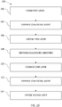
- FIG. 10 is a flow diagram illustrating one example of an additive manufacturing process 100 implemented in Figs. 1A-9A, 1B-9B .
- a first layer 12 of build material 14 is formed, as shown in Figs. 1A, 1B (block 102 in Fig. 10 ).
- a coalescing agent 16 is dispensed on to build material 14, as shown in Figs. 2A, 2B , in a pattern 20 corresponding to an object slice, for example with an inkjet type dispenser 18 (block 104 in Fig. 13 ).
- Coalescing agent pattern 20 is depicted by dense stippling in the figures. Any suitable build material 14 may be used to make object 10, shown in Figs. 9A and 9B , which may be hard or soft, rigid or flexible, elastic or inelastic. Also, while a powdered build material 14 is depicted by particles 22 in this example, suitable non-powdered build materials could also be used.
- the area 20 of layer 12 patterned with coalescing agent is exposed to light 24 from a light source 26 to coalesce build material and, upon solidification, form a first object slice 28 (block 106 in Fig. 10 ).
- the build material may coalesce, for example, by melting to a liquid or by sintering to a solid. If the build material melts, then solidification occurs upon cooling.
- a coalescence modifier agent 30 is dispensed on to slice 28 in a pattern 32 covering an area 34 where a second object slice will underhang the first slice (block 108 in Fig. 10 ), for example with an inkjet type dispenser 36.
- Modifier agent pattern 32 is depicted by sparse stippling in the figures. In the example shown, the pattern 32 for modifier agent 30 is coextensive with underhang area 34. Other underhang patterns 32 are possible.
- light source 26 is configured to selectively illuminate only those portions of build material patterned with coalescing agent, then it may be desirable to limit pattern 32 to locations immediately bordering the second slice pattern in the underhang areas. (Second slice pattern 44 is shown in Figs. 7A, 7B .) If, however, light source 26 is configured to illuminate most or all of each layer of build material, then it usually will be desirable for modifier agent pattern 32 to completely cover underhang area 34 as shown in Figs. 4A and 4B .
- Coalescence modifier agent 30 may also be dispensed on to other areas of build material in each layer to help define other aspects of the object slices including, for example, interspersed with the pattern of the coalescing agent to change the material characteristics of the slice.
- agents 16 and 30 could be dispensed from the same dispensers integrated into a single device, for example using different printheads (or groups of printheads) in a single inkjet printhead assembly.
- a liquid modifier agent 30 it may be desirable to dry the patterned area 32 before forming the next layer of build material.
- the area of slice 28 patterned with modifier agent is heated to dry the modifier agent and form a solid fusion barrier 38.
- Heater 40 in Fig. 5A represents generally any suitable heater, which may include one or more of thermal radiation, convection and conduction.
- a second layer 42 of build material 14 is formed over first layer 12 covering first slice 28 (block 110 in Fig. 10 ).
- a coalescing agent 16 is dispensed on to build material 14 in layer 42 in a pattern 44 corresponding to a second object slice underhanging first slice 28 (block 112 in Fig. 10 ).
- area 44 patterned with coalescing agent is exposed to light 24 to coalesce build material and, upon solidification, form a second object slice 46 (block 114 in Fig. 10 ). While distinct first and second slices 28, 46 are shown in Figs.
- Second slice 46 includes part 48 that underhangs first slice 46. While a simple two-slice object 10 is shown, the same process steps may be used to form more complex, multi-slice objects.
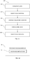
- Fig. 11 is a flow diagram illustrating another example of an additive manufacturing process 120.
- a first layer of build material is formed (block 122) and build material in the first layer solidified to form a first slice (block 124), for example as described above with reference to Figs. 1A-3A, 1B-3B .
- a coalescence modifier agent is dispensed on to the first slice covering an area where the first slice will underhang the second slice (block 126), for example as described above with reference to Figs. 4A and 4B .
- a second layer of build material is formed on the first layer of build material (block 128) and build material in the second layer is solidified to form a second slice on the first slice (block 130), for example as described above with reference to Figs.
- the modifier agent may be dried before forming the second layer of build material, for example by actively heating the modifier agent as shown in Figs. 5A and 5B .
- the heat in a newly formed slice may be sufficient to dry the liquid modifier agent without additional heating.
- FIG. 12 is a block diagram illustrating a processor readable medium 50 with instructions 52 to help form an underhang during the manufacture of a 3D object.
- a processor readable medium 50 is any non-transitory tangible medium that can embody, contain, store, or maintain instructions for use by a processor.
- Processor readable media include, for example, electronic, magnetic, optical, electromagnetic, or semiconductor media. More specific examples of suitable processor readable media include a hard drive, a random access memory (RAM), a read-only memory (ROM), memory cards and sticks and other portable storage devices.
- Underhang instructions 52 include instructions to inhibit build material in an overlying layer of build material from fusing with a first slice formed in an underlying layer of build material, for example by dispensing a coalescing modifier agent at block 126 in Fig. 11 .
- Instructions 52 may include other additive manufacturing instructions, for example instructions to form and solidify shown at blocks 122, 124, 128 and 130 in Fig. 11 .
- Processor readable medium 50 with instructions 52 may be implemented, for example, in a CAD computer program product, in an object model processor, or in a controller for an additive manufacturing machine. Control data to inhibit fusing can be generated, for example, by processor readable instructions on the source application, usually a CAD computer program product, in an object model processor, or by processor readable instructions on the additive manufacturing machine.
- Fig. 13 is a block diagram illustrating one example of an additive manufacturing machine 54 implementing a controller 56 with overhang instructions 52.
- machine 54 includes controller 56, a manufacturing bed or other suitable support 58, a roller or other suitable build material layering device 60, a coalescing agent dispenser 18, a coalescence modifier agent dispenser 36, a heater 40 and a light source 26.
- the in-process object structure is supported on support 58 during manufacturing.
- support 58 may be movable at the urging of controller 56 to compensate for the changing thickness of the in-process structure, for example as layers of build material are added during manufacturing.
- Build material layering device 60 layers build material on support 58 and on the in-process structures and may include, for example, a device to dispense the build material and a blade or roller to distribute the build material uniformly to the desired thickness for each layer.
- Coalescing agent dispenser 18 dispenses coalescing agent selectively at the direction of controller 56 on to build material, for example as described above with reference to Figs. 2A and 7A .
- Coalescence modifier agent dispenser 36 dispenses modifier agent selectively at the direction of controller 56 on to build material, for example as described above with reference to Fig. 4A .
- Manufacturing machine 54 may include a heater 40 if it is desired to pre-heat build material or to heat modifier agent.
- Light source 26 applies light 24 selectively at the direction of controller 56 to coalesce build material treated with coalescing agent, for example as described above with reference to Figs. 3A and 8A .
- Controller 56 represents the processor (or multiple processors), the associated memory (or multiple memories) and instructions, and the electronic circuitry and components needed to control the operative elements of machine 54.
- controller 56 includes a memory 62 having a processor readable medium 50 with underhang instructions 52, and a processor 64 to read and execute instructions 52.
- controller 56 would receive control data and other instructions from a CAD program to make an object that includes an overhang and execute local underhang instructions 52 as part of the process of making the object.
- underhang instructions 52 may be embodied in a processor readable medium 50 separate from controller 56, for example as part of a CAD computer program product shown in Fig. 14 .
- an additive manufacturing system 66 includes an additive manufacturing machine 54 operatively connected to a CAD computer program product 68 with underhang instructions 52 residing on a processor readable medium 50. Any suitable connection between machine 54 and CAD program product 68 may be used to communicate instructions and control data to machine 54 including, for example, a wired link, a wireless link, and a portable connection such as a flash drive or compact disk.
- Light source 26 applies light energy to build material to cause the coalescence of portions of the build material according to where coalescing agent has been delivered or has penetrated.
- light source 26 is an infra-red (IR) or near infra-red light source, or a halogen light source.
- IR infra-red
- Light source 26 may be a single light source or an array of multiple light sources.
- light source 26 is configured to apply light energy in a substantially uniform manner simultaneously to the whole surface of a layer of build material. In other examples, light source 26 is configured to apply energy to only select areas of the whole surface of a layer of build material.
- Build material may be a powder, a liquid, a paste, or a gel.
- Examples of build material include semi-crystalline thermoplastic materials with a processing window of greater than 5°C (i.e., the temperature range between the melting point and the re-crystallization temperature).
- Suitable build materials may include polyamides (e.g., PA or nylon 11, PA or nylon 12, PA or nylon 6, PA or nylon 8, PA or nylon 9, PA or nylon 66, PA or nylon 612, PA or nylon 812, PA or nylon 912), polyethylene, polyethylene terephthalate (PET), polystyrene, polyacetals, polypropylene, polycarbonate, polyester, thermal polyurethanes, other engineering plastics, and blends of any two or more of the polymers listed. Core shell polymer particles of these materials may also be used.
- Build material may have a melting point ranging from about 50°C to about 400°C. In some implementations, it is desirable that the melting point of the build material be less than (lower than) the melting point of an inorganic salt used in the modifier agent.
- polyamide 12 having a melting point of 180° may be used, or thermal polyurethanes having a melting point ranging from about 100°C to about 165°C may be used.
- at least one of the particles has a melting point below the melting point of the inorganic salt in the modifier agent.
- Build material may include, in addition to polymer particles, a charging agent and a flow aid.
- a charging agent may be added to suppress tribo-charging.
- Suitable charging agents may include aliphatic amines (which may be ethoxylated), aliphatic amides, quaternary ammonium salts (e.g., behentrimonium chloride or cocamidopropyl betaine), esters of phosphoric acid, polyethylene glycol esters, or polyols.
- HOSTASTAT® FA 38 natural based ethoxylated alkylamine
- HOSTASTAT® FE2 fatty acid ester
- HOSTASTAT® HS 1 alkane sulfonate
- Suitable flow aids include tricalcium phosphate (E341), powdered cellulose (E460(ii)), magnesium stearate (E470b), sodium bicarbonate (E500), sodium ferrocyanide (E535), potassium ferrocyanide (E536), calcium ferrocyanide (E538), bone phosphate (E542), sodium silicate (E550), silicon dioxide (E551), calcium silicate (E552), magnesium trisilicate (E553a), talcum powder (E553b), sodium aluminosilicate (E554), potassium aluminium silicate (E555), calcium aluminosilicate (E556), bentonite (E558), aluminium silicate (E559), stearic acid (E570), or polydimethylsiloxane (E900).
- the flow aid is added in an amount ranging from greater than 0 wt% to less than 5 wt% based upon the total wt% of the particles.
- Suitable coalescence modifier agents may separate individual particles of the build material to prevent the particles from coalescing.
- this type of modifier agent include colloidal, dye-based, and polymer-based inks, as well as solid particles that have an average size less than the average size of particles of the build material.
- the molecular mass of the modifier agent and its surface tension may be such that it enables the agent to penetrate sufficiently into the build material to achieve the desired mechanical separation.
- a salt solution may be used as a coalescence modifier agent.
- inks commercially known as CM996A and CN673A available from Hewlett-Packard Company may be used as a coalescence modifier agent.
- Suitable coalescence modifier agents may act to modify the effects of a coalescing agent by preventing build material from reaching the melting point.
- a fluid that exhibits a suitable cooling effect may be used as this type of coalescence modifier agent.
- energy applied to the build material may be absorbed evaporating the fluid to help prevent build material from reaching its melting point.
- a fluid with a high water content may be a suitable coalescence modifier agent.
Landscapes
- Chemical & Material Sciences (AREA)
- Engineering & Computer Science (AREA)
- Materials Engineering (AREA)
- Manufacturing & Machinery (AREA)
- Physics & Mathematics (AREA)
- Optics & Photonics (AREA)
- Mechanical Engineering (AREA)
- Health & Medical Sciences (AREA)
- Toxicology (AREA)
Claims (11)
- Procédé de fabrication additive (120), comprenant :la formation (122) d'une première couche de matériau de construction ;la solidification (124) de matériau de construction dans la première couche pour former une première tranche ;la distribution (126) d'un agent modificateur de coalescence comprenant une substance pour inhiber ou empêcher la coalescence du matériau de construction sur la première tranche couvrant une zone où la première tranche sera en retrait d'une seconde tranche ;la formation (128) d'une seconde couche de matériau de construction sur la première tranche ;la distribution d'un agent coalescent sur le matériau de construction dans la seconde couche ; etla solidification (130) de matériau de construction dans la seconde couche pour former la seconde tranche sur la première tranchela solidification de matériau de construction comportant la distribution d'un agent de coalescence sur le matériau de construction selon un modèle d'une tranche, puis l'application d'énergie lumineuse pour construire un matériau modelé à l'aide d'un agent de coalescence.
- Procédé selon la revendication 1, dans lequel l'agent modificateur est un agent modificateur liquide et le procédé comprend le séchage de l'agent modificateur sur la première tranche avant la formation de la seconde couche de matériau de construction.
- Procédé selon la revendication 2, dans lequel le séchage de l'agent modificateur comporte le chauffage de l'agent modificateur.
- Support lisible par processeur non transitoire (50) ayant des instructions (52) qui, lorsqu'elles sont exécutées, amènent une machine de fabrication additive à inhiber la fusion de matériau de construction dans une couche superposée de matériau de construction avec une première tranche formée dans une couche sous-jacente de matériau de construction, le support lisible par processeur non transitoire étant caractérisé en ce que les instructions pour inhiber la fusion de matériau de construction comportent des instructions pour :distribuer un agent modificateur de coalescence liquide, comprenant une substance pour inhiber ou empêcher une coalescence du matériau de construction sur la première tranche bordant une zone où une seconde tranche dans la couche superposée couvrira la première tranche ;le support lisible par processeur non transitoire possédant d'autres instructions qui, lorsqu'elles sont exécutées, amènent la machine de fabrication additive à :former une seconde couche de matériau de construction sur la première tranche : etsolidifier le matériau de construction dans la seconde couche pour former la seconde tranche sur la première tranche, la solidification d'un matériau de construction comportant le fait que la machine de fabrication additive distribue un agent de coalescence sur le matériau de construction selon un modèle de tranche, puis applique de l'énergie lumineuse au matériau de construction modelé à l'aide d'un agent de coalescence.
- Support selon la revendication 4, dans lequel les instructions pour inhiber la fusion de matériau de construction comportent des instructions pour :
sécher l'agent modificateur distribué sur la première tranche avant de former la couche superposée de matériau de construction. - Produit programme d'ordinateur qui comporte le support lisible par processeur de la revendication 5.
- Dispositif de commande de machine de fabrication additive qui comporte le support lisible par processeur de la revendication 4.
- Machine de fabrication additive (54), comprenant :un premier dispositif (60) pour superposer un matériau de construction en poudre ;un deuxième dispositif (18) étant adapté à distribuer un agent de coalescence sur un matériau de construction ;un troisième dispositif (36) étant adapté à distribuer un agent modificateur de coalescence comprenant une substance pour inhiber ou empêcher la coalescence du matériau de construction, sur un matériau de construction ;une source de lumière (26) pour appliquer de l'énergie lumineuse à un matériau de construction ; etun dispositif de commande (56) pour exécuter des instructions (52) pour :amener le premier dispositif à superposer un matériau de construction dans une première couche ;amener le deuxième dispositif à distribuer un agent de coalescence sur un matériau de construction dans la première couche selon un premier modèle d'une première tranche ;amener la source de lumière à appliquer de l'énergie lumineuse à un matériau de construction dans la première couche où l'agent coalescent a été distribué, pour former la première tranche ;amener le troisième dispositif à distribuer un agent modificateur de coalescence sur la première tranche bordant une zone où une seconde tranche couvrira la première tranche ;amener le premier dispositif à superposer un matériau de construction dans une seconde couche sur la première couche ;amener le deuxième dispositif à distribuer un agent de coalescence sur un matériau de construction dans la seconde couche selon un second modèle d'une seconde tranche ; etamener la source de lumière à appliquer de l'énergie lumineuse sur un matériau de construction dans la seconde couche où l'agent de coalescence a été distribué, pour former la seconde tranche sur la première tranche.
- Machine selon la revendication 8, dans laquelle l'agent modificateur est un agent modificateur liquide et le dispositif de commande doit exécuter des instructions pour sécher l'agent modificateur sur la première tranche avant de former la seconde couche de matériau de construction.
- Machine selon la revendication 9, dans laquelle les instructions pour sécher l'agent modificateur comportent des instructions pour chauffer l'agent modificateur.
- Machine selon la revendication 10, dans laquelle les instructions pour amener le troisième dispositif à distribuer un agent modificateur de coalescence sur la première tranche se trouvent dans le dispositif de commande.
Applications Claiming Priority (1)
| Application Number | Priority Date | Filing Date | Title |
|---|---|---|---|
| PCT/US2015/011368 WO2016114772A1 (fr) | 2015-01-14 | 2015-01-14 | Fabrication additive |
Publications (3)
| Publication Number | Publication Date |
|---|---|
| EP3245041A1 EP3245041A1 (fr) | 2017-11-22 |
| EP3245041A4 EP3245041A4 (fr) | 2018-08-22 |
| EP3245041B1 true EP3245041B1 (fr) | 2020-10-14 |
Family
ID=56406171
Family Applications (1)
| Application Number | Title | Priority Date | Filing Date |
|---|---|---|---|
| EP15878214.4A Active EP3245041B1 (fr) | 2015-01-14 | 2015-01-14 | Fabrication additive |
Country Status (4)
| Country | Link |
|---|---|
| US (2) | US11117322B2 (fr) |
| EP (1) | EP3245041B1 (fr) |
| CN (1) | CN107107471B (fr) |
| WO (1) | WO2016114772A1 (fr) |
Families Citing this family (2)
| Publication number | Priority date | Publication date | Assignee | Title |
|---|---|---|---|---|
| CN109070467B (zh) | 2016-04-04 | 2021-04-13 | 惠普发展公司,有限责任合伙企业 | 用于增材制造的防护特征的定义 |
| CN109562564B (zh) * | 2016-10-19 | 2021-07-23 | 惠普发展公司,有限责任合伙企业 | 增材制造 |
Family Cites Families (16)
| Publication number | Priority date | Publication date | Assignee | Title |
|---|---|---|---|---|
| US20020020945A1 (en) | 2000-08-18 | 2002-02-21 | Uichung Cho | Forming three dimensional objects through bulk heating of layers with differential material properties |
| EP1583652B1 (fr) * | 2002-12-20 | 2011-02-09 | University Of Southern California | Procedes de reduction des dechets de poudre dans un frittage a inhibition selective |
| US20040169699A1 (en) * | 2003-02-28 | 2004-09-02 | Hunter Shawn D. | Methods and systems for producing an object through solid freeform fabrication using immiscible fluids |
| DE102004020452A1 (de) * | 2004-04-27 | 2005-12-01 | Degussa Ag | Verfahren zur Herstellung von dreidimensionalen Objekten mittels elektromagnetischer Strahlung und Auftragen eines Absorbers per Inkjet-Verfahren |
| US7521652B2 (en) | 2004-12-07 | 2009-04-21 | 3D Systems, Inc. | Controlled cooling methods and apparatus for laser sintering part-cake |
| DE102006017194B4 (de) | 2006-04-12 | 2010-11-04 | Birgit Riesinger | Flüssigkeitsdurchlässiger Primärverband |
| US8765045B2 (en) | 2007-01-12 | 2014-07-01 | Stratasys, Inc. | Surface-treatment method for rapid-manufactured three-dimensional objects |
| WO2011065920A1 (fr) * | 2009-11-26 | 2011-06-03 | Yu En Tan | Procédé de construction d'objets en trois dimensions |
| EP2643148B1 (fr) * | 2010-11-28 | 2016-02-03 | Stratasys Ltd. | Système et procédé pour fabrication additive d'un objet |
| US8460755B2 (en) | 2011-04-07 | 2013-06-11 | Stratasys, Inc. | Extrusion-based additive manufacturing process with part annealing |
| US9943996B2 (en) | 2012-05-22 | 2018-04-17 | University Of Southern California | Process planning of meniscus shapes for fabricating smooth surfaces in mask image projection based additive manufacturing |
| US9636868B2 (en) | 2012-08-16 | 2017-05-02 | Stratasys, Inc. | Additive manufacturing system with extended printing volume, and methods of use thereof |
| US9403725B2 (en) | 2013-03-12 | 2016-08-02 | University Of Southern California | Inserting inhibitor to create part boundary isolation during 3D printing |
| WO2015108554A1 (fr) * | 2014-01-16 | 2015-07-23 | Hewlett-Packard Development Company, L.P. | Barrière de pénétration pour la fabrication additive |
| JP2015139977A (ja) * | 2014-01-30 | 2015-08-03 | セイコーエプソン株式会社 | 三次元造形物の製造方法および三次元造形物 |
| EP3188896B1 (fr) * | 2014-09-02 | 2021-05-26 | Hewlett-Packard Development Company, L.P. | Fabrication d'additifs pour porte-à-faux |
-
2015
- 2015-01-14 WO PCT/US2015/011368 patent/WO2016114772A1/fr active Application Filing
- 2015-01-14 US US15/520,826 patent/US11117322B2/en active Active
- 2015-01-14 CN CN201580058913.1A patent/CN107107471B/zh active Active
- 2015-01-14 EP EP15878214.4A patent/EP3245041B1/fr active Active
-
2021
- 2021-08-12 US US17/401,026 patent/US20210370597A1/en active Pending
Non-Patent Citations (1)
| Title |
|---|
| None * |
Also Published As
| Publication number | Publication date |
|---|---|
| WO2016114772A1 (fr) | 2016-07-21 |
| EP3245041A4 (fr) | 2018-08-22 |
| CN107107471B (zh) | 2021-01-15 |
| US20210370597A1 (en) | 2021-12-02 |
| US20170326799A1 (en) | 2017-11-16 |
| EP3245041A1 (fr) | 2017-11-22 |
| US11117322B2 (en) | 2021-09-14 |
| CN107107471A (zh) | 2017-08-29 |
Similar Documents
| Publication | Publication Date | Title |
|---|---|---|
| RU2693131C2 (ru) | Формирование трехмерного объекта | |
| US10434708B2 (en) | Three-dimensional (3D) printing method | |
| CN106232331B (zh) | 计算机模型和三维(3d)印刷方法 | |
| EP3233425B1 (fr) | Fabrication additive | |
| US20200114639A1 (en) | Additive manufacturing for an overhang | |
| US10688716B2 (en) | Consolidating a build material for additive manufacturing | |
| US20210370597A1 (en) | Additive manufacturing | |
| EP3389994B1 (fr) | Définition d'un élément de protection pour la fabrication additive | |
| KR20170100000A (ko) | 다중-구조의 3d 물체의 프린팅 | |
| BR112017015945B1 (pt) | Método de impressão tridimensional, sistema para impressão tridimensional e meio de armazenamento legível por máquina não transitório | |
| US20190176390A1 (en) | Three dimensional (3d) printing | |
| CN107206667A (zh) | 生成三维对象 | |
| JP2019089348A (ja) | 付加製造 | |
| JP6546306B2 (ja) | 三次元物体の生成 |
Legal Events
| Date | Code | Title | Description |
|---|---|---|---|
| STAA | Information on the status of an ep patent application or granted ep patent |
Free format text: STATUS: THE INTERNATIONAL PUBLICATION HAS BEEN MADE |
|
| PUAI | Public reference made under article 153(3) epc to a published international application that has entered the european phase |
Free format text: ORIGINAL CODE: 0009012 |
|
| STAA | Information on the status of an ep patent application or granted ep patent |
Free format text: STATUS: REQUEST FOR EXAMINATION WAS MADE |
|
| 17P | Request for examination filed |
Effective date: 20170413 |
|
| AK | Designated contracting states |
Kind code of ref document: A1 Designated state(s): AL AT BE BG CH CY CZ DE DK EE ES FI FR GB GR HR HU IE IS IT LI LT LU LV MC MK MT NL NO PL PT RO RS SE SI SK SM TR |
|
| AX | Request for extension of the european patent |
Extension state: BA ME |
|
| DAX | Request for extension of the european patent (deleted) | ||
| REG | Reference to a national code |
Ref country code: DE Ref legal event code: R079 Ref document number: 602015060629 Country of ref document: DE Free format text: PREVIOUS MAIN CLASS: B29C0067000000 Ipc: B29C0064165000 |
|
| A4 | Supplementary search report drawn up and despatched |
Effective date: 20180723 |
|
| RIC1 | Information provided on ipc code assigned before grant |
Ipc: B33Y 30/00 20150101ALN20180717BHEP Ipc: B33Y 50/02 20150101ALN20180717BHEP Ipc: B33Y 70/00 20150101ALN20180717BHEP Ipc: B33Y 10/00 20150101ALN20180717BHEP Ipc: B29C 64/165 20170101AFI20180717BHEP |
|
| RAP1 | Party data changed (applicant data changed or rights of an application transferred) |
Owner name: HEWLETT-PACKARD DEVELOPMENT COMPANY, L.P. |
|
| GRAP | Despatch of communication of intention to grant a patent |
Free format text: ORIGINAL CODE: EPIDOSNIGR1 |
|
| STAA | Information on the status of an ep patent application or granted ep patent |
Free format text: STATUS: GRANT OF PATENT IS INTENDED |
|
| INTG | Intention to grant announced |
Effective date: 20200107 |
|
| GRAJ | Information related to disapproval of communication of intention to grant by the applicant or resumption of examination proceedings by the epo deleted |
Free format text: ORIGINAL CODE: EPIDOSDIGR1 |
|
| STAA | Information on the status of an ep patent application or granted ep patent |
Free format text: STATUS: REQUEST FOR EXAMINATION WAS MADE |
|
| GRAP | Despatch of communication of intention to grant a patent |
Free format text: ORIGINAL CODE: EPIDOSNIGR1 |
|
| STAA | Information on the status of an ep patent application or granted ep patent |
Free format text: STATUS: GRANT OF PATENT IS INTENDED |
|
| INTC | Intention to grant announced (deleted) | ||
| INTG | Intention to grant announced |
Effective date: 20200608 |
|
| GRAS | Grant fee paid |
Free format text: ORIGINAL CODE: EPIDOSNIGR3 |
|
| GRAA | (expected) grant |
Free format text: ORIGINAL CODE: 0009210 |
|
| STAA | Information on the status of an ep patent application or granted ep patent |
Free format text: STATUS: THE PATENT HAS BEEN GRANTED |
|
| AK | Designated contracting states |
Kind code of ref document: B1 Designated state(s): AL AT BE BG CH CY CZ DE DK EE ES FI FR GB GR HR HU IE IS IT LI LT LU LV MC MK MT NL NO PL PT RO RS SE SI SK SM TR |
|
| REG | Reference to a national code |
Ref country code: GB Ref legal event code: FG4D |
|
| REG | Reference to a national code |
Ref country code: AT Ref legal event code: REF Ref document number: 1323149 Country of ref document: AT Kind code of ref document: T Effective date: 20201015 Ref country code: CH Ref legal event code: EP |
|
| REG | Reference to a national code |
Ref country code: DE Ref legal event code: R096 Ref document number: 602015060629 Country of ref document: DE |
|
| REG | Reference to a national code |
Ref country code: IE Ref legal event code: FG4D |
|
| REG | Reference to a national code |
Ref country code: AT Ref legal event code: MK05 Ref document number: 1323149 Country of ref document: AT Kind code of ref document: T Effective date: 20201014 |
|
| REG | Reference to a national code |
Ref country code: NL Ref legal event code: MP Effective date: 20201014 |
|
| PG25 | Lapsed in a contracting state [announced via postgrant information from national office to epo] |
Ref country code: PT Free format text: LAPSE BECAUSE OF FAILURE TO SUBMIT A TRANSLATION OF THE DESCRIPTION OR TO PAY THE FEE WITHIN THE PRESCRIBED TIME-LIMIT Effective date: 20210215 Ref country code: RS Free format text: LAPSE BECAUSE OF FAILURE TO SUBMIT A TRANSLATION OF THE DESCRIPTION OR TO PAY THE FEE WITHIN THE PRESCRIBED TIME-LIMIT Effective date: 20201014 Ref country code: FI Free format text: LAPSE BECAUSE OF FAILURE TO SUBMIT A TRANSLATION OF THE DESCRIPTION OR TO PAY THE FEE WITHIN THE PRESCRIBED TIME-LIMIT Effective date: 20201014 Ref country code: NO Free format text: LAPSE BECAUSE OF FAILURE TO SUBMIT A TRANSLATION OF THE DESCRIPTION OR TO PAY THE FEE WITHIN THE PRESCRIBED TIME-LIMIT Effective date: 20210114 Ref country code: NL Free format text: LAPSE BECAUSE OF FAILURE TO SUBMIT A TRANSLATION OF THE DESCRIPTION OR TO PAY THE FEE WITHIN THE PRESCRIBED TIME-LIMIT Effective date: 20201014 Ref country code: GR Free format text: LAPSE BECAUSE OF FAILURE TO SUBMIT A TRANSLATION OF THE DESCRIPTION OR TO PAY THE FEE WITHIN THE PRESCRIBED TIME-LIMIT Effective date: 20210115 |
|
| REG | Reference to a national code |
Ref country code: LT Ref legal event code: MG4D |
|
| PG25 | Lapsed in a contracting state [announced via postgrant information from national office to epo] |
Ref country code: ES Free format text: LAPSE BECAUSE OF FAILURE TO SUBMIT A TRANSLATION OF THE DESCRIPTION OR TO PAY THE FEE WITHIN THE PRESCRIBED TIME-LIMIT Effective date: 20201014 Ref country code: AT Free format text: LAPSE BECAUSE OF FAILURE TO SUBMIT A TRANSLATION OF THE DESCRIPTION OR TO PAY THE FEE WITHIN THE PRESCRIBED TIME-LIMIT Effective date: 20201014 Ref country code: BG Free format text: LAPSE BECAUSE OF FAILURE TO SUBMIT A TRANSLATION OF THE DESCRIPTION OR TO PAY THE FEE WITHIN THE PRESCRIBED TIME-LIMIT Effective date: 20210114 Ref country code: LV Free format text: LAPSE BECAUSE OF FAILURE TO SUBMIT A TRANSLATION OF THE DESCRIPTION OR TO PAY THE FEE WITHIN THE PRESCRIBED TIME-LIMIT Effective date: 20201014 Ref country code: PL Free format text: LAPSE BECAUSE OF FAILURE TO SUBMIT A TRANSLATION OF THE DESCRIPTION OR TO PAY THE FEE WITHIN THE PRESCRIBED TIME-LIMIT Effective date: 20201014 Ref country code: SE Free format text: LAPSE BECAUSE OF FAILURE TO SUBMIT A TRANSLATION OF THE DESCRIPTION OR TO PAY THE FEE WITHIN THE PRESCRIBED TIME-LIMIT Effective date: 20201014 Ref country code: IS Free format text: LAPSE BECAUSE OF FAILURE TO SUBMIT A TRANSLATION OF THE DESCRIPTION OR TO PAY THE FEE WITHIN THE PRESCRIBED TIME-LIMIT Effective date: 20210214 |
|
| PG25 | Lapsed in a contracting state [announced via postgrant information from national office to epo] |
Ref country code: HR Free format text: LAPSE BECAUSE OF FAILURE TO SUBMIT A TRANSLATION OF THE DESCRIPTION OR TO PAY THE FEE WITHIN THE PRESCRIBED TIME-LIMIT Effective date: 20201014 |
|
| REG | Reference to a national code |
Ref country code: DE Ref legal event code: R097 Ref document number: 602015060629 Country of ref document: DE |
|
| PG25 | Lapsed in a contracting state [announced via postgrant information from national office to epo] |
Ref country code: SK Free format text: LAPSE BECAUSE OF FAILURE TO SUBMIT A TRANSLATION OF THE DESCRIPTION OR TO PAY THE FEE WITHIN THE PRESCRIBED TIME-LIMIT Effective date: 20201014 Ref country code: RO Free format text: LAPSE BECAUSE OF FAILURE TO SUBMIT A TRANSLATION OF THE DESCRIPTION OR TO PAY THE FEE WITHIN THE PRESCRIBED TIME-LIMIT Effective date: 20201014 Ref country code: EE Free format text: LAPSE BECAUSE OF FAILURE TO SUBMIT A TRANSLATION OF THE DESCRIPTION OR TO PAY THE FEE WITHIN THE PRESCRIBED TIME-LIMIT Effective date: 20201014 Ref country code: CZ Free format text: LAPSE BECAUSE OF FAILURE TO SUBMIT A TRANSLATION OF THE DESCRIPTION OR TO PAY THE FEE WITHIN THE PRESCRIBED TIME-LIMIT Effective date: 20201014 Ref country code: SM Free format text: LAPSE BECAUSE OF FAILURE TO SUBMIT A TRANSLATION OF THE DESCRIPTION OR TO PAY THE FEE WITHIN THE PRESCRIBED TIME-LIMIT Effective date: 20201014 Ref country code: LT Free format text: LAPSE BECAUSE OF FAILURE TO SUBMIT A TRANSLATION OF THE DESCRIPTION OR TO PAY THE FEE WITHIN THE PRESCRIBED TIME-LIMIT Effective date: 20201014 |
|
| PLBE | No opposition filed within time limit |
Free format text: ORIGINAL CODE: 0009261 |
|
| STAA | Information on the status of an ep patent application or granted ep patent |
Free format text: STATUS: NO OPPOSITION FILED WITHIN TIME LIMIT |
|
| PG25 | Lapsed in a contracting state [announced via postgrant information from national office to epo] |
Ref country code: DK Free format text: LAPSE BECAUSE OF FAILURE TO SUBMIT A TRANSLATION OF THE DESCRIPTION OR TO PAY THE FEE WITHIN THE PRESCRIBED TIME-LIMIT Effective date: 20201014 Ref country code: MC Free format text: LAPSE BECAUSE OF FAILURE TO SUBMIT A TRANSLATION OF THE DESCRIPTION OR TO PAY THE FEE WITHIN THE PRESCRIBED TIME-LIMIT Effective date: 20201014 |
|
| REG | Reference to a national code |
Ref country code: CH Ref legal event code: PL |
|
| 26N | No opposition filed |
Effective date: 20210715 |
|
| PG25 | Lapsed in a contracting state [announced via postgrant information from national office to epo] |
Ref country code: LU Free format text: LAPSE BECAUSE OF NON-PAYMENT OF DUE FEES Effective date: 20210114 |
|
| REG | Reference to a national code |
Ref country code: BE Ref legal event code: MM Effective date: 20210131 |
|
| PG25 | Lapsed in a contracting state [announced via postgrant information from national office to epo] |
Ref country code: AL Free format text: LAPSE BECAUSE OF FAILURE TO SUBMIT A TRANSLATION OF THE DESCRIPTION OR TO PAY THE FEE WITHIN THE PRESCRIBED TIME-LIMIT Effective date: 20201014 Ref country code: IT Free format text: LAPSE BECAUSE OF FAILURE TO SUBMIT A TRANSLATION OF THE DESCRIPTION OR TO PAY THE FEE WITHIN THE PRESCRIBED TIME-LIMIT Effective date: 20201014 |
|
| PG25 | Lapsed in a contracting state [announced via postgrant information from national office to epo] |
Ref country code: SI Free format text: LAPSE BECAUSE OF FAILURE TO SUBMIT A TRANSLATION OF THE DESCRIPTION OR TO PAY THE FEE WITHIN THE PRESCRIBED TIME-LIMIT Effective date: 20201014 Ref country code: CH Free format text: LAPSE BECAUSE OF NON-PAYMENT OF DUE FEES Effective date: 20210131 Ref country code: LI Free format text: LAPSE BECAUSE OF NON-PAYMENT OF DUE FEES Effective date: 20210131 |
|
| PG25 | Lapsed in a contracting state [announced via postgrant information from national office to epo] |
Ref country code: IE Free format text: LAPSE BECAUSE OF NON-PAYMENT OF DUE FEES Effective date: 20210114 |
|
| PG25 | Lapsed in a contracting state [announced via postgrant information from national office to epo] |
Ref country code: IS Free format text: LAPSE BECAUSE OF FAILURE TO SUBMIT A TRANSLATION OF THE DESCRIPTION OR TO PAY THE FEE WITHIN THE PRESCRIBED TIME-LIMIT Effective date: 20210214 |
|
| PG25 | Lapsed in a contracting state [announced via postgrant information from national office to epo] |
Ref country code: BE Free format text: LAPSE BECAUSE OF NON-PAYMENT OF DUE FEES Effective date: 20210131 |
|
| PG25 | Lapsed in a contracting state [announced via postgrant information from national office to epo] |
Ref country code: HU Free format text: LAPSE BECAUSE OF FAILURE TO SUBMIT A TRANSLATION OF THE DESCRIPTION OR TO PAY THE FEE WITHIN THE PRESCRIBED TIME-LIMIT; INVALID AB INITIO Effective date: 20150114 |
|
| PGFP | Annual fee paid to national office [announced via postgrant information from national office to epo] |
Ref country code: DE Payment date: 20221220 Year of fee payment: 9 |
|
| PG25 | Lapsed in a contracting state [announced via postgrant information from national office to epo] |
Ref country code: CY Free format text: LAPSE BECAUSE OF FAILURE TO SUBMIT A TRANSLATION OF THE DESCRIPTION OR TO PAY THE FEE WITHIN THE PRESCRIBED TIME-LIMIT Effective date: 20201014 |
|
| PGFP | Annual fee paid to national office [announced via postgrant information from national office to epo] |
Ref country code: GB Payment date: 20231219 Year of fee payment: 10 |
|
| PGFP | Annual fee paid to national office [announced via postgrant information from national office to epo] |
Ref country code: FR Payment date: 20231219 Year of fee payment: 10 |
|
| PG25 | Lapsed in a contracting state [announced via postgrant information from national office to epo] |
Ref country code: MK Free format text: LAPSE BECAUSE OF FAILURE TO SUBMIT A TRANSLATION OF THE DESCRIPTION OR TO PAY THE FEE WITHIN THE PRESCRIBED TIME-LIMIT Effective date: 20201014 |
|
| PGFP | Annual fee paid to national office [announced via postgrant information from national office to epo] |
Ref country code: DE Payment date: 20231219 Year of fee payment: 10 |