EP3245012B1 - Support for tensioned screening media - Google Patents
Support for tensioned screening media Download PDFInfo
- Publication number
- EP3245012B1 EP3245012B1 EP15701136.2A EP15701136A EP3245012B1 EP 3245012 B1 EP3245012 B1 EP 3245012B1 EP 15701136 A EP15701136 A EP 15701136A EP 3245012 B1 EP3245012 B1 EP 3245012B1
- Authority
- EP
- European Patent Office
- Prior art keywords
- capping
- media
- neck
- arms
- flanges
- Prior art date
- Legal status (The legal status is an assumption and is not a legal conclusion. Google has not performed a legal analysis and makes no representation as to the accuracy of the status listed.)
- Active
Links
Images


Classifications
-
- B—PERFORMING OPERATIONS; TRANSPORTING
- B07—SEPARATING SOLIDS FROM SOLIDS; SORTING
- B07B—SEPARATING SOLIDS FROM SOLIDS BY SIEVING, SCREENING, SIFTING OR BY USING GAS CURRENTS; SEPARATING BY OTHER DRY METHODS APPLICABLE TO BULK MATERIAL, e.g. LOOSE ARTICLES FIT TO BE HANDLED LIKE BULK MATERIAL
- B07B1/00—Sieving, screening, sifting, or sorting solid materials using networks, gratings, grids, or the like
- B07B1/12—Apparatus having only parallel elements
- B07B1/16—Apparatus having only parallel elements the elements being movable and in other than roller form
-
- B—PERFORMING OPERATIONS; TRANSPORTING
- B07—SEPARATING SOLIDS FROM SOLIDS; SORTING
- B07B—SEPARATING SOLIDS FROM SOLIDS BY SIEVING, SCREENING, SIFTING OR BY USING GAS CURRENTS; SEPARATING BY OTHER DRY METHODS APPLICABLE TO BULK MATERIAL, e.g. LOOSE ARTICLES FIT TO BE HANDLED LIKE BULK MATERIAL
- B07B1/00—Sieving, screening, sifting, or sorting solid materials using networks, gratings, grids, or the like
- B07B1/46—Constructional details of screens in general; Cleaning or heating of screens
-
- B—PERFORMING OPERATIONS; TRANSPORTING
- B07—SEPARATING SOLIDS FROM SOLIDS; SORTING
- B07B—SEPARATING SOLIDS FROM SOLIDS BY SIEVING, SCREENING, SIFTING OR BY USING GAS CURRENTS; SEPARATING BY OTHER DRY METHODS APPLICABLE TO BULK MATERIAL, e.g. LOOSE ARTICLES FIT TO BE HANDLED LIKE BULK MATERIAL
- B07B1/00—Sieving, screening, sifting, or sorting solid materials using networks, gratings, grids, or the like
- B07B1/46—Constructional details of screens in general; Cleaning or heating of screens
- B07B1/4609—Constructional details of screens in general; Cleaning or heating of screens constructional details of screening surfaces or meshes
-
- B—PERFORMING OPERATIONS; TRANSPORTING
- B07—SEPARATING SOLIDS FROM SOLIDS; SORTING
- B07B—SEPARATING SOLIDS FROM SOLIDS BY SIEVING, SCREENING, SIFTING OR BY USING GAS CURRENTS; SEPARATING BY OTHER DRY METHODS APPLICABLE TO BULK MATERIAL, e.g. LOOSE ARTICLES FIT TO BE HANDLED LIKE BULK MATERIAL
- B07B1/00—Sieving, screening, sifting, or sorting solid materials using networks, gratings, grids, or the like
- B07B1/46—Constructional details of screens in general; Cleaning or heating of screens
- B07B1/4609—Constructional details of screens in general; Cleaning or heating of screens constructional details of screening surfaces or meshes
- B07B1/4645—Screening surfaces built up of modular elements
-
- B—PERFORMING OPERATIONS; TRANSPORTING
- B07—SEPARATING SOLIDS FROM SOLIDS; SORTING
- B07B—SEPARATING SOLIDS FROM SOLIDS BY SIEVING, SCREENING, SIFTING OR BY USING GAS CURRENTS; SEPARATING BY OTHER DRY METHODS APPLICABLE TO BULK MATERIAL, e.g. LOOSE ARTICLES FIT TO BE HANDLED LIKE BULK MATERIAL
- B07B1/00—Sieving, screening, sifting, or sorting solid materials using networks, gratings, grids, or the like
- B07B1/46—Constructional details of screens in general; Cleaning or heating of screens
- B07B1/48—Stretching devices for screens
-
- B—PERFORMING OPERATIONS; TRANSPORTING
- B07—SEPARATING SOLIDS FROM SOLIDS; SORTING
- B07B—SEPARATING SOLIDS FROM SOLIDS BY SIEVING, SCREENING, SIFTING OR BY USING GAS CURRENTS; SEPARATING BY OTHER DRY METHODS APPLICABLE TO BULK MATERIAL, e.g. LOOSE ARTICLES FIT TO BE HANDLED LIKE BULK MATERIAL
- B07B1/00—Sieving, screening, sifting, or sorting solid materials using networks, gratings, grids, or the like
- B07B1/28—Moving screens not otherwise provided for, e.g. swinging, reciprocating, rocking, tilting or wobbling screens
- B07B1/36—Moving screens not otherwise provided for, e.g. swinging, reciprocating, rocking, tilting or wobbling screens jigging or moving to-and-fro in more than one direction
Definitions
- the present invention relates to a capping to support tensioned screening media at a screen deck.
- Screening apparatus such as vibrating screen decks are used for a variety of applications and may comprise interchangeable square or rectangular screen elements that provide a screen surface upon which bulk material may be deposited and graded by size.
- the screen (commonly referred to as the screening media) may be of a cross-tensioned, length-tensioned or pre-tensioned media type having a sheet-like structure that extends between lengthwise extending sides of the screen deck.
- the tensioned screening media may be formed from wire mesh, metal sheet or reinforced polyurethane/rubber.
- Wire mesh media is advantageous as it is easy to mount, relatively low cost and includes a large open structure to facilitate screening a greater range of stone or gravel fractions.
- Cross-tensioned and length-tensioned screening media is mounted in the vibrating screen using hooks or fastenings attached to the side or end walls of the screen deck whilst pre-tensioned media is typically pressed downwardly onto the lower support frame by abutment brackets also mounted at the side or end walls.
- the screen media is supported from below by support beams spaced apart and arranged parallel to the sidewalls.
- the support beams are typically arranged at different heights in order to support media between the sidewalls in a crowned profile (or upwardly raised or hump-shaped) when secured in position.
- Vibrating screen decks may also comprise modular screen elements in which the screening media comprises interchangeable panels that are tessellated together between the deck walls.
- An example modular screening deck is described in US 4,219,412 .
- Hybrid screen decks are also known comprising both the tensioned and modular media as described in US 2008/0257719 .
- Modular screen decks are disadvantageous as the modular panels are manufacturer specific and are therefore higher cost and not as accessible as tensioned screening media.
- Example tensioned screening media decks are described in JP 2012/076054 , US2255939 and WO 2005/092523 .
- JP 2012/076054 discloses ' cappings ' that are mounted on top of the parallel support beams to provide a cushioned support for the media and avoid accelerated wear due to friction.
- the media comprises a continuously open structure along its length
- stones or gravel it is common for stones or gravel to become lodged between the media and the cappings which both affects how the media sits upon the deck frame (by changing its orientation angle) and significantly increases the abrasion contact between the capping and the media to accelerate wear.
- screening media with ' blinds ' (elongate strip regions of the media that are devoid of screening apertures) spaced apart along the length of the media with these blinds configured to be supported directly from below by the cappings in an attempt to address the problem of stone entrapment.
- alignment of the ' blinds ' with the cappings is not always optimised and also such non-standardised media tends to be higher cost and not as accessible. Accordingly, what is required is screening apparatus that addresses the above problems.
- a capping having arms configured to clamp onto the media support beam and a head configured to support an underside surface of the screening media where the head is flexible so as to provide and maintain close-touching contact with the underside surface of the media to effectively ' close ' the open mesh or apertures of the media at its underside surface.
- the head of the capping is separated from the arms by a neck such that the head comprises laterally outward extending flanges that are configured to flex and compress downwardly towards the arms when positioned to support the media from below.
- a media contact surface of the head When in the supporting configuration, in contact with the underside surface of the media, a media contact surface of the head is arranged to be substantially co-planar with the media underside surface and in particular not to curve or be declined downwardly away from the media underside surface that would otherwise create pockets between the media surface and the head for entrapment of stones and gravel.
- an elongate capping to support tensioned screening media at a screen deck comprising: a pair of opposed spaced apart arms between which is defined a channel to receive and mount the capping on a longitudinal carrier beam of the screen deck; characterised by: a neck provided at one end of and forming a bridge between the arms; and a head provided at the neck and having flexible flanges that extend laterally outward from the neck, the flanges configured to flex and resiliently compress towards the arms to support the screen media when mounted under tension on the head.
- the head comprises a media contact surface that extends over the flanges, the contact surface being generally concave in a lateral widthwise direction of the head between respective endmost edges of the flanges.
- the contact surface may be considered to be inclined over each flange in a lateral widthwise direction of the head relative to a central region positioned over the neck.
- a distance by which each flange extends laterally outward from the neck is in a range 40 to 80%, 50 to 70% or more preferably 55 to 65% of a thickness of the neck in a lateral widthwise direction of the capping.
- This relative ' overhang ' of the flanges beyond the neck ensures the flanges are provided with sufficient flex to bend downwardly towards the arms to support the media in the crowned or upwardly curved orientation.
- the flanges are separated from the arms in a height direction of the capping by a length of the neck in the height direction and a shoulder region of each arm at a junction with the neck is declined to slope downwardly away from each respective flange.
- the downwardly sloping shoulders of the upper ends of arm increase the range of available flex of each flange to provide appropriate cushioning of the media during use.
- a thickness of each flange in a height direction of the capping increases in a lateral widthwise direction of the head such that widthwise outer regions of the flanges are thicker than corresponding widthwise inner regions of the flanges that form a junction with the neck.
- the capping further comprises a plurality of fingers extending from each of the arms into the channel.
- the fingers are inclined to extend in a direction within the channel towards the neck.
- each capping comprises two arms and three fingers on each of the respective arms, the fingers spaced apart in a height direction of the capping between a first end of each arm furthest from the neck and a second end of each arm connected to the neck.
- the fingers comprise a uniform thickness between their innermost ends positioned at the inner region of the channel and a base region of each finger provided at the junction with each arm.
- the thicknesses of the fingers may taper.
- the fingers may comprise barbed, profiled, ribbed or dimpled surface profiles to increase the frictional contact with the carrier beam to provide a secure mounting of the capping.
- the capping comprises a flexible material such that the flanges are resiliently compressible towards the arms.
- the fingers are resiliently compressible towards each respective arm.
- the fingers and flanges are configured to bend when positioned in contact with the carrier beam and media, respectively and to return to their non-flexed configuration when the capping is either detached from the carrier beam or the media.
- the arms are resiliently expandable to open the channel to receive and mount the capping.
- the flexible fingers and/or arms are advantageous to provide a universal capping suitable for mounting upon support beams of different dimensions and geometries.
- the capping is formed as a moulded single unitary body and comprises a rubber or a polyurethane material.
- a screen deck comprising: a frame having a plurality of carrier beams; a tensioned screening media supported upon the carrier beams; and a plurality of cappings as claimed herein mounting upon the carrier beams to support in touching contact the screening media.
- the screening media comprises an open structure or a plurality of apertures to allow the downward passage of media, the open structure or apertures extending continuously along a length of the media in a direction perpendicular to the carrier beams such that the cappings are positioned directly below the open structure or apertures and are configured to blind the open structure or apertures at a region of the media immediately above each respective capping.
- the screening media comprises a mesh, a steel mesh, a sheet material, a metal sheet, a rubber or polyurethane layer or sheet all comprising gaps or apertures to allow the downward passage of material to be screened such as gravel, stones and the like.
- a vibrating screen deck comprises sheet-like cross-tensioned screening media 100 onto which may be deposited bulk material to be screened such as stones, gravel and the like.
- Media 100 typically comprises rubber or polyurethane and comprises an open structure (aperture) through which the bulk material may fall when deposited on an uppermost surface 201.
- Media 100 at its endmost edges 106 comprises hooks (not shown) for attachment to a fastening (not shown) provided on the sidewalls (not shown) of the screen deck so as to mount the media 100 under tension.
- a plurality of support beams 101 extend parallel to one another and to the sidewalls of the screen deck so as to be aligned generally perpendicular to the length of media 100 between end edges 106.
- Beams 101 typically comprise steel and have a generally rectangular cross-sectional profile having a lower elongate end surface 202 and an upper elongate end surface 203 positioned closest to and directly below an underside surface 200 of media 100.
- each capping 102 is mounted on the end surface 203 so as to shroud the upper half of each support beam 101 and provide a cushioned mounting and support of the media 100 at the screen deck.
- each capping 102 is formed from a resiliently deformable material such as a rubber or a polyurethane.
- the open structure or apertures within the media 100 extend continuously between the endmost edges 106 such that the cappings 102 are positioned directly below the open structure or apertures so as to ' blind ' them from the underside surface 200. That is, media 100 is devoid of any generally solid or non-aperture regions (as is known in the art) positioned conventionally immediately above the cappings 102.
- Each capping 102 comprises a first lower region 105 configured for mounting and gripping onto the generally upper half of a respective support beam 101, and a second upper region 104 for positioning in contact with the lower planar surface 200 of media 100.
- Second region 104 comprises a media contact surface 103 positioned in direct contact with media underside surface 200.
- the lowermost end surface 202 of beams 101 is attached or mounted to further frame parts (not shown) of the screen deck.
- each capping 102 is generally elongate so as to comprise a main length in the z axis and a corresponding width in the lateral sideways direction of axis y. Accordingly, capping 102 is divided in the x axis (corresponding to a height of the capping 102) into the lower first region 105 configured to grip and mount at a respective support beam 101 and the generally upper second region 104 to support directly media 100 via its lowermost or downward facing surface 200.
- Lower region 105 is formed generally by a pair of elongate arms 105 whilst upper region 104 is formed generally by an elongate head 104 mounted at arms 105 via a neck 301.
- Arms 105 are spaced apart in the y axis so as to define a channel 303 being elongate in the z direction.
- channel 303 is defined between opposed inner faces 400 of each of the opposed arms 105 and a generally downward facing abutment surface 306 positioned directly below neck 301.
- a width of channel 303 in the y axis is slightly greater than a corresponding width of a support beam 101 so as to allow capping 102 to be mounted onto the uppermost end of beam 101 via abutment between capping abutment surface 306 and beam end surface 203.
- each arm 105 When mounted in position as illustrated in figure 3 , the inner faces 400 of each arm 105 are positioned opposed and substantially coplanar with the side faces 300 of support beam 101 that extend in the x axis between the upper and lower end surfaces 202, 203.
- a plurality of flexible elongate fingers 304 project into channel 303 from each of the opposed inner faces 400 of each arm 105.
- Each of the fingers 304 are spaced apart at each face 300 in the height direction of capping 102 (x axis) and are inclined upwardly such that the innermost ends of each finger 304 are positioned closest to neck 301 relative to base regions of each finger 304 (formed at the junction with each respective arm 105).
- each of the fingers 304 is configured to flex and bend in the upward direction towards abutment surface 306 as the tips of each of the fingers brush against each of the beam side faces 300.
- the flexible fingers 304 are advantageous to provide a universal capping 102 suitable for mounting upon beams 101 of different width in the y axis. That is, wider support beams may be accommodated within channel 303 as fingers 304 are capable of flexing upwardly into the space between the adjacent arms 105 and the beam side faces 300.
- the inclined orientation of the fingers 304 is further advantageous to both increase the contact surface area with the beam side faces 300 and to be resistant to decoupling of the capping 102 from each beam 101 via a downward movement of beam 101 involving separation of the mating contact between abutment surface 306 and beam end face 203.
- neck 301 provides a junction or bridge between the spaced apart arms 105 in the widthwise y direction and also provides separation in the height direction (x axis) of capping 102 between arms 105 and head 104.
- a height of neck 301 in the x axis is approximately equal to or slightly less than a height of head 104 (immediately above neck 301).
- a width B of neck 301 in the y axis is less than a corresponding width of head 104 such that lateral end regions of head 104 overhand neck 301.
- a cross sectional profile of capping 102 perpendicular to its longitudinal length in the z axis comprises a generally T-shaped profile.
- Head 104 may therefore be considered to comprise lengthwise extending flanges 302 that extend laterally outward beyond neck 301 (in the y axis) being spatially separated in the height direction of capping 102 (in the x axis) by a distance corresponding to the height of neck 301 above arms 105. Accordingly, flanges 302 are separated from arms 105 by respective lengthwise extending channels 305 that allow flanges 302 to compress and bend downwardly in the x axis towards arms 105 when media contact surface 103 is positioned in contact with the underside surface 200 of media 100. According to the specific implementation, a height in the x axis of each channel 305 is approximately equal to a corresponding height of neck 301.
- a width of each channel 305 increases in the laterally outward direction from neck 301 as an upper surface 502 at a shoulder region of each arm 105 is declined downwardly at an angle ⁇ relative to an opposed downward facing surface 503 of each flange 302.
- ⁇ is in the range 25 to 35°.
- the upward facing media contact surface 103 at each flange 302 is inclined in the upward direction by an angle ⁇ . That is, head 104 at the media contact surface 103 may be divided in the widthwise direction into three sections including a central elongate section 500a positioned directly above neck 301 and two lateral side sections 500b positioned immediately above each flange 302. According to the specific implementation, surface 103 at sections 500b is orientated to be upwardly inclined at an angle 10 to 15° relative to the surface 103 at central section 500a.
- flanges 302 are configured to deflect downwardly into respective channels 305 to ensure the entire surface area of media contact surface 103 is positioned in complete contact with the media underside surface 200.
- Such an arrangement is advantageous to close or ' blind ' the open structure of the media 100 directly above each capping 102 and accordingly prevent stones or gravel becoming entrapped in the regions immediately above the cappings 102.
- media contact surface 103 in the y axis may be considered to be concave or to comprise central innermost section 500a that is depressed in the height direction of axis x relative to the flange side sections 500b.
- Stabilisation of the mounted position of the cappings 102 is achieved, in part, due to the extended surface area contact between head 104 and media surface 200 in the widthwise y axis. Stones and gravel are inhibited further from becoming entrapped at the region of capping head 104 as the flanges 302 comprise an undercut surface 504 that tapers inwardly towards neck 301 from a laterally outermost edge 501 of each flange 302. Flanges 302 overhang arms 105 in the lateral widthwise direction (y axis) such that head 104 is wider than arms 105.
- a maximum width A across both arms 105 at a region immediately above channel 303 is approximately 80% of a maximum width D of head 104.
- arms 105 may also be configured to flex or bend laterally outward in the y axis so as to accommodate support beams 101 of different thickness. Such an arrangement provides a universal capping 102 suitable for mounting upon support beams 101 of different dimensions and geometries.
- capping 102 comprising arms 105, neck 301, and head 104 is formed as a unitary body from a resiliently compressible material.
- head 104 (and optionally neck 301) may be formed from a first material being different to arms 105 (and optionally fingers 304) formed from a second material having different mechanical and physical properties relative to the first material.
Landscapes
- Combined Means For Separation Of Solids (AREA)
- Ink Jet (AREA)
- Toys (AREA)
- User Interface Of Digital Computer (AREA)
- Investigating Strength Of Materials By Application Of Mechanical Stress (AREA)
Description
- The present invention relates to a capping to support tensioned screening media at a screen deck.
- Screening apparatus such as vibrating screen decks are used for a variety of applications and may comprise interchangeable square or rectangular screen elements that provide a screen surface upon which bulk material may be deposited and graded by size. Alternatively, the screen (commonly referred to as the screening media) may be of a cross-tensioned, length-tensioned or pre-tensioned media type having a sheet-like structure that extends between lengthwise extending sides of the screen deck. In particular, the tensioned screening media may be formed from wire mesh, metal sheet or reinforced polyurethane/rubber.
- Wire mesh media is advantageous as it is easy to mount, relatively low cost and includes a large open structure to facilitate screening a greater range of stone or gravel fractions. Cross-tensioned and length-tensioned screening media is mounted in the vibrating screen using hooks or fastenings attached to the side or end walls of the screen deck whilst pre-tensioned media is typically pressed downwardly onto the lower support frame by abutment brackets also mounted at the side or end walls. The screen media is supported from below by support beams spaced apart and arranged parallel to the sidewalls. The support beams are typically arranged at different heights in order to support media between the sidewalls in a crowned profile (or upwardly raised or hump-shaped) when secured in position.
Vibrating screen decks may also comprise modular screen elements in which the screening media comprises interchangeable panels that are tessellated together between the deck walls. An example modular screening deck is described inUS 4,219,412 . Hybrid screen decks are also known comprising both the tensioned and modular media as described inUS 2008/0257719 . Modular screen decks are disadvantageous as the modular panels are manufacturer specific and are therefore higher cost and not as accessible as tensioned screening media. - Example tensioned screening media decks are described in
JP 2012/076054 US2255939 andWO 2005/092523 .JP 2012/076054 - It is an objective of the present invention to provide screening apparatus and in particular a capping for a screening media support beam that is configured to support tensioned screening media having an open structure or apertures that extend continuously along the length of the screening media between its lengthwise ends (positioned at the sidewalls of the screen deck). It is a further specific objective to provide a support capping that does not facilitate entrapment of stones or gravel between the capping and the screening media during use. It is a yet further objective to provide a capping that facilitates mounting of cross-tensioned, length-tensioned or pre-tensioned screening mediate to create a crowned or humped-shaped screen deck that is effective to 'blind' the media from below so as to effectively close the open structure or apertures at the region of each capping.
- The objectives are achieved by providing a capping having arms configured to clamp onto the media support beam and a head configured to support an underside surface of the screening media where the head is flexible so as to provide and maintain close-touching contact with the underside surface of the media to effectively 'close' the open mesh or apertures of the media at its underside surface. In particular, the head of the capping is separated from the arms by a neck such that the head comprises laterally outward extending flanges that are configured to flex and compress downwardly towards the arms when positioned to support the media from below. When in the supporting configuration, in contact with the underside surface of the media, a media contact surface of the head is arranged to be substantially co-planar with the media underside surface and in particular not to curve or be declined downwardly away from the media underside surface that would otherwise create pockets between the media surface and the head for entrapment of stones and gravel.
- According to a first aspect of the present invention there is provided an elongate capping to support tensioned screening media at a screen deck, the capping comprising: a pair of opposed spaced apart arms between which is defined a channel to receive and mount the capping on a longitudinal carrier beam of the screen deck; characterised by: a neck provided at one end of and forming a bridge between the arms; and a head provided at the neck and having flexible flanges that extend laterally outward from the neck, the flanges configured to flex and resiliently compress towards the arms to support the screen media when mounted under tension on the head.
- Preferably, the head comprises a media contact surface that extends over the flanges, the contact surface being generally concave in a lateral widthwise direction of the head between respective endmost edges of the flanges. Optionally, the contact surface may be considered to be inclined over each flange in a lateral widthwise direction of the head relative to a central region positioned over the neck. Such an arrangement is advantageous to provide complete contact between the surface of the capping head and the underside surface of the media to completely close or blind the media open structure or apertures at a region directly above the capping. Stones and gravel are accordingly prevented from being entrapped at the region of each capping.
- Preferably, a distance by which each flange extends laterally outward from the neck is in a range 40 to 80%, 50 to 70% or more preferably 55 to 65% of a thickness of the neck in a lateral widthwise direction of the capping. This relative 'overhang' of the flanges beyond the neck ensures the flanges are provided with sufficient flex to bend downwardly towards the arms to support the media in the crowned or upwardly curved orientation.
- Preferably, the flanges are separated from the arms in a height direction of the capping by a length of the neck in the height direction and a shoulder region of each arm at a junction with the neck is declined to slope downwardly away from each respective flange. The downwardly sloping shoulders of the upper ends of arm increase the range of available flex of each flange to provide appropriate cushioning of the media during use. Preferably, a thickness of each flange in a height direction of the capping increases in a lateral widthwise direction of the head such that widthwise outer regions of the flanges are thicker than corresponding widthwise inner regions of the flanges that form a junction with the neck. Such an arrangement is convenient for manufacture and provides the concave or laterally raised shaped profile of the media contact surface of the head without compromising the integrity of the capping.
- Preferably, the capping further comprises a plurality of fingers extending from each of the arms into the channel. Preferably, the fingers are inclined to extend in a direction within the channel towards the neck. Optionally, each capping comprises two arms and three fingers on each of the respective arms, the fingers spaced apart in a height direction of the capping between a first end of each arm furthest from the neck and a second end of each arm connected to the neck. Optionally, the fingers comprise a uniform thickness between their innermost ends positioned at the inner region of the channel and a base region of each finger provided at the junction with each arm. However, according to further implementations, the thicknesses of the fingers may taper. Optionally, the fingers may comprise barbed, profiled, ribbed or dimpled surface profiles to increase the frictional contact with the carrier beam to provide a secure mounting of the capping.
- Preferably, the capping comprises a flexible material such that the flanges are resiliently compressible towards the arms. Preferably, the fingers are resiliently compressible towards each respective arm. Accordingly, the fingers and flanges are configured to bend when positioned in contact with the carrier beam and media, respectively and to return to their non-flexed configuration when the capping is either detached from the carrier beam or the media. Preferably, the arms are resiliently expandable to open the channel to receive and mount the capping. The flexible fingers and/or arms are advantageous to provide a universal capping suitable for mounting upon support beams of different dimensions and geometries. Optionally, the capping is formed as a moulded single unitary body and comprises a rubber or a polyurethane material.
- According to a second aspect of the present invention there is provided a screen deck comprising: a frame having a plurality of carrier beams; a tensioned screening media supported upon the carrier beams; and a plurality of cappings as claimed herein mounting upon the carrier beams to support in touching contact the screening media.
- Preferably, the screening media comprises an open structure or a plurality of apertures to allow the downward passage of media, the open structure or apertures extending continuously along a length of the media in a direction perpendicular to the carrier beams such that the cappings are positioned directly below the open structure or apertures and are configured to blind the open structure or apertures at a region of the media immediately above each respective capping. Optionally, the screening media comprises a mesh, a steel mesh, a sheet material, a metal sheet, a rubber or polyurethane layer or sheet all comprising gaps or apertures to allow the downward passage of material to be screened such as gravel, stones and the like.
- A specific implementation of the present invention will now be described, by way of example only, and with reference to the accompanying drawings in which:
-
Figure 1 is a perspective view of a part of a vibrating screen deck comprising cross-tensioned screening media supported upon a plurality of support beams and cappings according to a specific implementation of the present invention; -
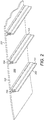
Figure 2 is an underside perspective view of the screening media and cappings offigure 1 ; -
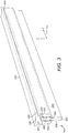
Figure 3 is a perspective view of a support beam and capping offigure 2 ; -
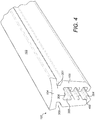
Figure 4 is a perspective view of the capping offigure 3 ; -
Figure 5 is an end view of the capping offigure 4 . - Referring to
figures 1 and2 , a vibrating screen deck comprises sheet-likecross-tensioned screening media 100 onto which may be deposited bulk material to be screened such as stones, gravel and the like.Media 100 typically comprises rubber or polyurethane and comprises an open structure (aperture) through which the bulk material may fall when deposited on anuppermost surface 201.Media 100 at itsendmost edges 106 comprises hooks (not shown) for attachment to a fastening (not shown) provided on the sidewalls (not shown) of the screen deck so as to mount themedia 100 under tension. A plurality ofsupport beams 101 extend parallel to one another and to the sidewalls of the screen deck so as to be aligned generally perpendicular to the length ofmedia 100 betweenend edges 106.Beams 101 typically comprise steel and have a generally rectangular cross-sectional profile having a lowerelongate end surface 202 and an upperelongate end surface 203 positioned closest to and directly below anunderside surface 200 ofmedia 100. -
Media 100 is supported indirectly from below by the support beams 101. Direct support is provided by a plurality ofcappings 102 mounted on the upper ends of thebeams 101 such that thecappings 102 are positionedintermediate media 100 and each of thebeams 101. In particular, each capping 102 is mounted on theend surface 203 so as to shroud the upper half of eachsupport beam 101 and provide a cushioned mounting and support of themedia 100 at the screen deck. Such an arrangement is advantageous to avoid accelerated wear of themedia 100 andbeams 101 due to the frictional contact during use. To provide the cushion support, each capping 102 is formed from a resiliently deformable material such as a rubber or a polyurethane. - According to the specific implementation, the open structure or apertures within the
media 100 extend continuously between theendmost edges 106 such that thecappings 102 are positioned directly below the open structure or apertures so as to 'blind' them from theunderside surface 200. That is,media 100 is devoid of any generally solid or non-aperture regions (as is known in the art) positioned conventionally immediately above thecappings 102. - Each capping 102 comprises a first
lower region 105 configured for mounting and gripping onto the generally upper half of arespective support beam 101, and a secondupper region 104 for positioning in contact with the lowerplanar surface 200 ofmedia 100.Second region 104 comprises amedia contact surface 103 positioned in direct contact withmedia underside surface 200. As will be appreciated, thelowermost end surface 202 ofbeams 101 is attached or mounted to further frame parts (not shown) of the screen deck. - Referring to
figures 3 and4 , each capping 102 is generally elongate so as to comprise a main length in the z axis and a corresponding width in the lateral sideways direction of axis y. Accordingly, capping 102 is divided in the x axis (corresponding to a height of the capping 102) into the lowerfirst region 105 configured to grip and mount at arespective support beam 101 and the generally uppersecond region 104 to support directlymedia 100 via its lowermost or downward facingsurface 200.Lower region 105 is formed generally by a pair ofelongate arms 105 whilstupper region 104 is formed generally by anelongate head 104 mounted atarms 105 via aneck 301.Arms 105 are spaced apart in the y axis so as to define achannel 303 being elongate in the z direction. In particular,channel 303 is defined between opposedinner faces 400 of each of theopposed arms 105 and a generally downward facingabutment surface 306 positioned directly belowneck 301. A width ofchannel 303 in the y axis is slightly greater than a corresponding width of asupport beam 101 so as to allow capping 102 to be mounted onto the uppermost end ofbeam 101 via abutment between cappingabutment surface 306 andbeam end surface 203. When mounted in position as illustrated infigure 3 , the inner faces 400 of eacharm 105 are positioned opposed and substantially coplanar with the side faces 300 ofsupport beam 101 that extend in the x axis between the upper and lower end surfaces 202, 203. A plurality of flexibleelongate fingers 304 project intochannel 303 from each of the opposed inner faces 400 of eacharm 105. Each of thefingers 304 are spaced apart at eachface 300 in the height direction of capping 102 (x axis) and are inclined upwardly such that the innermost ends of eachfinger 304 are positioned closest toneck 301 relative to base regions of each finger 304 (formed at the junction with each respective arm 105). Accordingly, during mounting of capping 102 ontosupport beam 101, each of thefingers 304 is configured to flex and bend in the upward direction towardsabutment surface 306 as the tips of each of the fingers brush against each of the beam side faces 300. Theflexible fingers 304 are advantageous to provide auniversal capping 102 suitable for mounting uponbeams 101 of different width in the y axis. That is, wider support beams may be accommodated withinchannel 303 asfingers 304 are capable of flexing upwardly into the space between theadjacent arms 105 and the beam side faces 300. The inclined orientation of thefingers 304 is further advantageous to both increase the contact surface area with the beam side faces 300 and to be resistant to decoupling of the capping 102 from eachbeam 101 via a downward movement ofbeam 101 involving separation of the mating contact betweenabutment surface 306 andbeam end face 203. - Referring to
figures 3 to 5 ,neck 301 provides a junction or bridge between the spaced apartarms 105 in the widthwise y direction and also provides separation in the height direction (x axis) of capping 102 betweenarms 105 andhead 104. Referring tofigure 5 , a height ofneck 301 in the x axis is approximately equal to or slightly less than a height of head 104 (immediately above neck 301). Advantageously, a width B ofneck 301 in the y axis is less than a corresponding width ofhead 104 such that lateral end regions ofhead 104overhand neck 301. Accordingly, a cross sectional profile of capping 102 perpendicular to its longitudinal length in the z axis comprises a generally T-shaped profile.Head 104 may therefore be considered to comprise lengthwise extendingflanges 302 that extend laterally outward beyond neck 301 (in the y axis) being spatially separated in the height direction of capping 102 (in the x axis) by a distance corresponding to the height ofneck 301 abovearms 105. Accordingly,flanges 302 are separated fromarms 105 by respective lengthwise extendingchannels 305 that allowflanges 302 to compress and bend downwardly in the x axis towardsarms 105 whenmedia contact surface 103 is positioned in contact with theunderside surface 200 ofmedia 100. According to the specific implementation, a height in the x axis of eachchannel 305 is approximately equal to a corresponding height ofneck 301. However, according to the specific implementation, a width of eachchannel 305 increases in the laterally outward direction fromneck 301 as anupper surface 502 at a shoulder region of eacharm 105 is declined downwardly at an angle θ relative to an opposed downward facingsurface 503 of eachflange 302. According to the specific implementation, θ is in the range 25 to 35°. Such an arrangement is advantageous to provide sufficient clearance for the flex offlanges 302 when capping 102 is placed in contact to support the underside ofmedia 100 in the crowned orientation between the screen deck sidewalls (not shown). Also, to ensure the head in both its lengthwise and widthwise directions (corresponding to the z and x axes) is maintained in close touching contact with themedia underside surface 200, the upward facingmedia contact surface 103 at eachflange 302 is inclined in the upward direction by an angle α. That is,head 104 at themedia contact surface 103 may be divided in the widthwise direction into three sections including a centralelongate section 500a positioned directly aboveneck 301 and twolateral side sections 500b positioned immediately above eachflange 302. According to the specific implementation,surface 103 atsections 500b is orientated to be upwardly inclined at an angle 10 to 15° relative to thesurface 103 atcentral section 500a. Accordingly, as thehead 104 is brought into contact withmedia surface 200,flanges 302 are configured to deflect downwardly intorespective channels 305 to ensure the entire surface area ofmedia contact surface 103 is positioned in complete contact with themedia underside surface 200. Such an arrangement is advantageous to close or 'blind' the open structure of themedia 100 directly above each capping 102 and accordingly prevent stones or gravel becoming entrapped in the regions immediately above thecappings 102. As theuppermost surfaces 103 offlanges 302 atsections 500b are inclined upwardly,media contact surface 103 in the y axis may be considered to be concave or to comprise centralinnermost section 500a that is depressed in the height direction of axis x relative to theflange side sections 500b. - Stabilisation of the mounted position of the
cappings 102 is achieved, in part, due to the extended surface area contact betweenhead 104 and media surface 200 in the widthwise y axis. Stones and gravel are inhibited further from becoming entrapped at the region of cappinghead 104 as theflanges 302 comprise an undercutsurface 504 that tapers inwardly towardsneck 301 from a laterallyoutermost edge 501 of eachflange 302.Flanges 302overhang arms 105 in the lateral widthwise direction (y axis) such thathead 104 is wider thanarms 105. In particular, a maximum width A across botharms 105 at a region immediately abovechannel 303 is approximately 80% of a maximum width D ofhead 104. - In addition to the flexing of
flanges 302 andfingers 304,arms 105 may also be configured to flex or bend laterally outward in the y axis so as to accommodatesupport beams 101 of different thickness. Such an arrangement provides auniversal capping 102 suitable for mounting upon support beams 101 of different dimensions and geometries. - According to the specific implementation, capping 102 comprising
arms 105,neck 301, andhead 104 is formed as a unitary body from a resiliently compressible material. - However, according to further specific implementations, head 104 (and optionally neck 301) may be formed from a first material being different to arms 105 (and optionally fingers 304) formed from a second material having different mechanical and physical properties relative to the first material.
Claims (15)
- An elongate capping (102) to support tensioned screening media (100) at a screen deck, the capping (102) comprising:a pair of opposed spaced apart arms (105) between which is defined a channel (303) to receive and mount the capping (102) on a longitudinal carrier beam (101) of the screen deck;characterised by:a neck (301) provided at one end of and forming a bridge between the arms (105); anda head (104) provided at the neck (301) and having flexible flanges (302) that extend laterally outward from the neck (301), the flanges (302) configured to flex and resiliently compress towards the arms (105) to support the screen media (100) when mounted under tension on the head (104).
- The capping as claimed in claim 1 wherein the head (104) comprises a media (100) contact surface (103) that extends over the flanges (302), the contact surface (103) being generally concave in a lateral widthwise direction of the head (104) between respective endmost edges (501) of the flanges (302).
- The capping as claimed in claim 1 wherein the head (104) comprises a media contact surface (103) that extends over the flanges (302), the contact surface (103) being inclined over each flange (302) in a lateral widthwise direction of the head (104) relative to a central region (500a) positioned over the neck (301).
- The capping as claimed in any preceding claim wherein a distance by which each flange (302) extends laterally outward from the neck (301) is in a range 40 to 80% of a thickness of the neck (301) in a lateral widthwise direction of the capping (102).
- The capping as claimed in claim 4 wherein the range is 50 to 70%.
- The capping as claimed in any preceding claim wherein the flanges (302) are separated from the arms (105) in a height direction of the capping (102) by a length of the neck (301) in the height direction and a shoulder region (502) of each arm (105) at a junction with the neck (301) is declined to slope downwardly away from each respective flange (302).
- The capping as claimed in any preceding claim wherein a thickness of each flange (302) in a height direction of the capping (102) increases in a lateral widthwise direction of the head (104) such that widthwise outer regions of the flanges (302) are thicker than corresponding widthwise inner regions of the flanges (302) that form a junction with the neck (301).
- The capping as claimed in any preceding claim further comprising a plurality of fingers (304) extending from each of the arms (105) into the channel (303).
- The capping as claimed in claim 8 wherein the fingers (304) are inclined to extend in a direction within the channel (303) towards the neck (301).
- The capping as claimed in claims 8 or 9 comprising two arms (105) and three fingers (304) on each of the respective arms (105), the fingers (304) spaced apart in a height direction of the capping (102) between a first end of each arm furthest from the neck (301) and a second end of each arm (105) connected to the neck (301).
- The capping as claimed in any preceding claim comprising a flexible material such that the flanges (302) are resiliently compressible towards the arms (105).
- The capping as claimed in claim 11 when dependent on any one of claims 8 to 10 wherein the fingers (304) are resiliently compressible towards each respective arm (105) and/or the arms (105) are resiliently expandable to open the channel (303) to receive and mount the capping (102).
- The capping as claimed in claims 11 or 12 wherein the flexible material comprises a rubber or a polyurethane.
- A screen deck comprising:a frame having a plurality of carrier beams (101);a tensioned screening media (100) supported upon the carrier beams (101); anda plurality of cappings (102) as claimed in any preceding claim mounting upon the carrier beams (101) to support in touching contact the screening media (100).
- The screen deck as claimed in claim 14 wherein the screening media (100) comprises an open structure or a plurality of apertures to allow the downward passage of media (100), the open structure or apertures extending continuously along a length of the media (100) in a direction perpendicular to the carrier beams (101) such that the cappings (102) are positioned directly below the open structure or apertures and are configured to blind the open structure or apertures at a region of the media (100) immediately above each respective capping (102).
Priority Applications (1)
| Application Number | Priority Date | Filing Date | Title |
|---|---|---|---|
| PL15701136T PL3245012T3 (en) | 2015-01-16 | 2015-01-16 | Support for tensioned screening media |
Applications Claiming Priority (1)
| Application Number | Priority Date | Filing Date | Title |
|---|---|---|---|
| PCT/EP2015/050777 WO2016112994A1 (en) | 2015-01-16 | 2015-01-16 | Support for tensioned screening media |
Publications (2)
| Publication Number | Publication Date |
|---|---|
| EP3245012A1 EP3245012A1 (en) | 2017-11-22 |
| EP3245012B1 true EP3245012B1 (en) | 2018-12-19 |
Family
ID=52396667
Family Applications (1)
| Application Number | Title | Priority Date | Filing Date |
|---|---|---|---|
| EP15701136.2A Active EP3245012B1 (en) | 2015-01-16 | 2015-01-16 | Support for tensioned screening media |
Country Status (12)
| Country | Link |
|---|---|
| US (1) | US9962739B2 (en) |
| EP (1) | EP3245012B1 (en) |
| CN (1) | CN107206430B (en) |
| AU (1) | AU2015377940B2 (en) |
| BR (1) | BR112017015232B1 (en) |
| CA (1) | CA2970961C (en) |
| DK (1) | DK3245012T3 (en) |
| ES (1) | ES2716684T3 (en) |
| PL (1) | PL3245012T3 (en) |
| RU (1) | RU2664082C1 (en) |
| WO (1) | WO2016112994A1 (en) |
| ZA (1) | ZA201704218B (en) |
Families Citing this family (5)
| Publication number | Priority date | Publication date | Assignee | Title |
|---|---|---|---|---|
| WO2020057719A1 (en) | 2018-09-17 | 2020-03-26 | Sandvik Srp Ab | Support for screening media |
| US11091077B2 (en) * | 2019-08-30 | 2021-08-17 | Lear Corporation | Retaining arrangement for a vehicle seat |
| US12318812B2 (en) * | 2023-01-13 | 2025-06-03 | Derrick Corporation | Apparatuses, methods, and systems for vibratory screening |
| CN117259196B (en) * | 2023-09-25 | 2024-02-06 | 四川沃耐稀新材料科技有限公司 | Lanthanum chloride cooling crystallization screening plant |
| EP4725619A1 (en) * | 2024-10-08 | 2026-04-15 | Bühler AG | Seal for a screen frame |
Family Cites Families (23)
| Publication number | Priority date | Publication date | Assignee | Title |
|---|---|---|---|---|
| US2255939A (en) * | 1939-02-25 | 1941-09-16 | Gustave A Overstrom | Screen |
| US2790552A (en) * | 1953-01-07 | 1957-04-30 | Nordberg Manufacturing Co | Heavy duty rod grizzly |
| FR1089947A (en) * | 1953-04-09 | 1955-03-24 | Screening device and its applications | |
| DE2706277C3 (en) * | 1977-02-15 | 1979-12-13 | Hein, Lehmann Ag, 4000 Duesseldorf | Sieve bottom |
| GB1600604A (en) | 1977-04-07 | 1981-10-21 | Greening N Ltd | Support frame for a screeing machine |
| ZA774472B (en) * | 1977-07-25 | 1979-06-27 | Herrmann Screens Mfg Co Ltd | Improvements in or relating to screening apparatus |
| DE3425485A1 (en) * | 1984-07-11 | 1986-01-16 | Hein, Lehmann AG, 4000 Düsseldorf | SCREENING |
| SU1505601A1 (en) * | 1987-09-16 | 1989-09-07 | Специальное конструкторско-технологическое бюро Института геотехнической механики АН УССР | Arrangement for securing elastic sieve |
| US5248043A (en) * | 1992-02-28 | 1993-09-28 | Dorn Lloyd A | Modular retro-fit screen system for a screening deck |
| AUPO213796A0 (en) * | 1996-09-05 | 1996-09-26 | Lettela Proprietary Limited | Modular screen panel |
| WO2002074454A1 (en) * | 2001-03-19 | 2002-09-26 | Ludwig Krieger Draht- Und Kunststofferzeugnisse Gmbh | Screening panel and screening machine fitted with same |
| US6957741B2 (en) * | 2001-08-07 | 2005-10-25 | Manfred Franz Axel Freissle | Screening arrangement |
| DE20204123U1 (en) * | 2002-03-15 | 2002-05-23 | Ludwig Krieger Draht- und Kunststofferzeugnisse GmbH, 76139 Karlsruhe | Screen covering, side protection for a screen covering and screening device with such a screen covering |
| SE527499C2 (en) | 2004-03-26 | 2006-03-21 | Sandvik Intellectual Property | Adapter device and vibration screen including an adapter device |
| CN101010149A (en) * | 2004-08-20 | 2007-08-01 | 瓦克I/P公司 | Screen assembly and shale shaker |
| SE530929C2 (en) * | 2007-04-19 | 2008-10-21 | Sandvik Intellectual Property | Support structure for a vibration layer and a support carrier thereof |
| US20080257719A1 (en) | 2007-04-21 | 2008-10-23 | Ted Suratt | Apparatus And Method For Making Flammable Gas |
| SE534711C2 (en) * | 2010-03-15 | 2011-11-29 | Sandvik Intellectual Property | Support carriers of a vibration screen support structure |
| US8887922B2 (en) * | 2010-04-12 | 2014-11-18 | Norris Screen And Manufacturing, Llc | Screen deck assembly |
| JP2012076054A (en) * | 2010-10-05 | 2012-04-19 | Hitachi Constr Mach Co Ltd | Vibrating screen |
| CN203030523U (en) * | 2012-10-22 | 2013-07-03 | 河南太行振动机械股份有限公司 | Support tensioning device for sieve plate |
| CN203155536U (en) * | 2013-03-04 | 2013-08-28 | 安徽方园塑胶有限责任公司 | Rail chair type durable support member for sieve plate |
| CA2932099C (en) * | 2015-06-05 | 2021-06-29 | Drilling Fluids Treatment Systems Inc. | Dual deck vibratory separator |
-
2015
- 2015-01-16 BR BR112017015232-0A patent/BR112017015232B1/en not_active IP Right Cessation
- 2015-01-16 CA CA2970961A patent/CA2970961C/en active Active
- 2015-01-16 AU AU2015377940A patent/AU2015377940B2/en not_active Ceased
- 2015-01-16 WO PCT/EP2015/050777 patent/WO2016112994A1/en not_active Ceased
- 2015-01-16 PL PL15701136T patent/PL3245012T3/en unknown
- 2015-01-16 RU RU2017128926A patent/RU2664082C1/en active
- 2015-01-16 ES ES15701136T patent/ES2716684T3/en active Active
- 2015-01-16 CN CN201580072709.5A patent/CN107206430B/en not_active Expired - Fee Related
- 2015-01-16 EP EP15701136.2A patent/EP3245012B1/en active Active
- 2015-01-16 DK DK15701136.2T patent/DK3245012T3/en active
- 2015-01-16 US US15/543,520 patent/US9962739B2/en active Active
-
2017
- 2017-06-21 ZA ZA2017/04218A patent/ZA201704218B/en unknown
Non-Patent Citations (1)
| Title |
|---|
| None * |
Also Published As
| Publication number | Publication date |
|---|---|
| ZA201704218B (en) | 2019-06-26 |
| WO2016112994A1 (en) | 2016-07-21 |
| PL3245012T3 (en) | 2019-07-31 |
| EP3245012A1 (en) | 2017-11-22 |
| BR112017015232A2 (en) | 2018-01-09 |
| AU2015377940A1 (en) | 2017-06-29 |
| US9962739B2 (en) | 2018-05-08 |
| CN107206430B (en) | 2019-11-19 |
| BR112017015232B1 (en) | 2020-12-29 |
| RU2664082C1 (en) | 2018-08-15 |
| ES2716684T3 (en) | 2019-06-14 |
| CA2970961A1 (en) | 2016-07-21 |
| US20170368577A1 (en) | 2017-12-28 |
| DK3245012T3 (en) | 2019-03-11 |
| CN107206430A (en) | 2017-09-26 |
| CA2970961C (en) | 2022-03-08 |
| AU2015377940B2 (en) | 2018-07-12 |
Similar Documents
| Publication | Publication Date | Title |
|---|---|---|
| AU2015377940B2 (en) | Support for tensioned screening media | |
| CA2681085C (en) | Supporting structure and a support carrier | |
| AU608392B2 (en) | Screening arrangement | |
| EP2008951B1 (en) | Reciprocating slat conveyors | |
| CN104837571A (en) | Snap fit fixing system for screen panels | |
| US8887922B2 (en) | Screen deck assembly | |
| CA2547114C (en) | A screening module | |
| US20130008833A1 (en) | Screen surface forming system | |
| CA2605711C (en) | A screening module | |
| CA2920437C (en) | Screen panel locking system | |
| AU2011221605B2 (en) | A vibrating screen having modular screening media | |
| US8196753B2 (en) | Screening panel | |
| EP4397603A1 (en) | Conveyor belt cleat | |
| US9085415B2 (en) | Conveyer belt for round produce | |
| AU2019283997B2 (en) | Method and apparatuses for screening | |
| AU2004292332B2 (en) | A screening module | |
| AU2013204826B2 (en) | Supporting structure and a support carrier | |
| AU2006238330B2 (en) | A screening module | |
| KR20160003654A (en) | Liner unit for chute wall |
Legal Events
| Date | Code | Title | Description |
|---|---|---|---|
| STAA | Information on the status of an ep patent application or granted ep patent |
Free format text: STATUS: THE INTERNATIONAL PUBLICATION HAS BEEN MADE |
|
| PUAI | Public reference made under article 153(3) epc to a published international application that has entered the european phase |
Free format text: ORIGINAL CODE: 0009012 |
|
| STAA | Information on the status of an ep patent application or granted ep patent |
Free format text: STATUS: REQUEST FOR EXAMINATION WAS MADE |
|
| 17P | Request for examination filed |
Effective date: 20170816 |
|
| AK | Designated contracting states |
Kind code of ref document: A1 Designated state(s): AL AT BE BG CH CY CZ DE DK EE ES FI FR GB GR HR HU IE IS IT LI LT LU LV MC MK MT NL NO PL PT RO RS SE SI SK SM TR |
|
| AX | Request for extension of the european patent |
Extension state: BA ME |
|
| DAX | Request for extension of the european patent (deleted) | ||
| GRAP | Despatch of communication of intention to grant a patent |
Free format text: ORIGINAL CODE: EPIDOSNIGR1 |
|
| STAA | Information on the status of an ep patent application or granted ep patent |
Free format text: STATUS: GRANT OF PATENT IS INTENDED |
|
| RIC1 | Information provided on ipc code assigned before grant |
Ipc: F16B 2/22 20060101ALI20180730BHEP Ipc: B07B 1/36 20060101ALI20180730BHEP Ipc: B07B 1/48 20060101ALI20180730BHEP Ipc: B07B 1/46 20060101AFI20180730BHEP |
|
| INTG | Intention to grant announced |
Effective date: 20180824 |
|
| GRAS | Grant fee paid |
Free format text: ORIGINAL CODE: EPIDOSNIGR3 |
|
| GRAA | (expected) grant |
Free format text: ORIGINAL CODE: 0009210 |
|
| STAA | Information on the status of an ep patent application or granted ep patent |
Free format text: STATUS: THE PATENT HAS BEEN GRANTED |
|
| AK | Designated contracting states |
Kind code of ref document: B1 Designated state(s): AL AT BE BG CH CY CZ DE DK EE ES FI FR GB GR HR HU IE IS IT LI LT LU LV MC MK MT NL NO PL PT RO RS SE SI SK SM TR |
|
| REG | Reference to a national code |
Ref country code: GB Ref legal event code: FG4D |
|
| REG | Reference to a national code |
Ref country code: CH Ref legal event code: EP |
|
| REG | Reference to a national code |
Ref country code: IE Ref legal event code: FG4D |
|
| REG | Reference to a national code |
Ref country code: DE Ref legal event code: R096 Ref document number: 602015021812 Country of ref document: DE |
|
| REG | Reference to a national code |
Ref country code: AT Ref legal event code: REF Ref document number: 1078129 Country of ref document: AT Kind code of ref document: T Effective date: 20190115 |
|
| REG | Reference to a national code |
Ref country code: DK Ref legal event code: T3 Effective date: 20190307 |
|
| REG | Reference to a national code |
Ref country code: SE Ref legal event code: TRGR |
|
| REG | Reference to a national code |
Ref country code: NL Ref legal event code: MP Effective date: 20181219 |
|
| PG25 | Lapsed in a contracting state [announced via postgrant information from national office to epo] |
Ref country code: LV Free format text: LAPSE BECAUSE OF FAILURE TO SUBMIT A TRANSLATION OF THE DESCRIPTION OR TO PAY THE FEE WITHIN THE PRESCRIBED TIME-LIMIT Effective date: 20181219 Ref country code: LT Free format text: LAPSE BECAUSE OF FAILURE TO SUBMIT A TRANSLATION OF THE DESCRIPTION OR TO PAY THE FEE WITHIN THE PRESCRIBED TIME-LIMIT Effective date: 20181219 Ref country code: BG Free format text: LAPSE BECAUSE OF FAILURE TO SUBMIT A TRANSLATION OF THE DESCRIPTION OR TO PAY THE FEE WITHIN THE PRESCRIBED TIME-LIMIT Effective date: 20190319 Ref country code: HR Free format text: LAPSE BECAUSE OF FAILURE TO SUBMIT A TRANSLATION OF THE DESCRIPTION OR TO PAY THE FEE WITHIN THE PRESCRIBED TIME-LIMIT Effective date: 20181219 |
|
| REG | Reference to a national code |
Ref country code: LT Ref legal event code: MG4D |
|
| REG | Reference to a national code |
Ref country code: NO Ref legal event code: T2 Effective date: 20181219 |
|
| REG | Reference to a national code |
Ref country code: AT Ref legal event code: MK05 Ref document number: 1078129 Country of ref document: AT Kind code of ref document: T Effective date: 20181219 |
|
| PG25 | Lapsed in a contracting state [announced via postgrant information from national office to epo] |
Ref country code: AL Free format text: LAPSE BECAUSE OF FAILURE TO SUBMIT A TRANSLATION OF THE DESCRIPTION OR TO PAY THE FEE WITHIN THE PRESCRIBED TIME-LIMIT Effective date: 20181219 Ref country code: RS Free format text: LAPSE BECAUSE OF FAILURE TO SUBMIT A TRANSLATION OF THE DESCRIPTION OR TO PAY THE FEE WITHIN THE PRESCRIBED TIME-LIMIT Effective date: 20181219 Ref country code: GR Free format text: LAPSE BECAUSE OF FAILURE TO SUBMIT A TRANSLATION OF THE DESCRIPTION OR TO PAY THE FEE WITHIN THE PRESCRIBED TIME-LIMIT Effective date: 20190320 |
|
| REG | Reference to a national code |
Ref country code: ES Ref legal event code: FG2A Ref document number: 2716684 Country of ref document: ES Kind code of ref document: T3 Effective date: 20190614 |
|
| PG25 | Lapsed in a contracting state [announced via postgrant information from national office to epo] |
Ref country code: NL Free format text: LAPSE BECAUSE OF FAILURE TO SUBMIT A TRANSLATION OF THE DESCRIPTION OR TO PAY THE FEE WITHIN THE PRESCRIBED TIME-LIMIT Effective date: 20181219 |
|
| PG25 | Lapsed in a contracting state [announced via postgrant information from national office to epo] |
Ref country code: PT Free format text: LAPSE BECAUSE OF FAILURE TO SUBMIT A TRANSLATION OF THE DESCRIPTION OR TO PAY THE FEE WITHIN THE PRESCRIBED TIME-LIMIT Effective date: 20190419 Ref country code: IT Free format text: LAPSE BECAUSE OF FAILURE TO SUBMIT A TRANSLATION OF THE DESCRIPTION OR TO PAY THE FEE WITHIN THE PRESCRIBED TIME-LIMIT Effective date: 20181219 Ref country code: CZ Free format text: LAPSE BECAUSE OF FAILURE TO SUBMIT A TRANSLATION OF THE DESCRIPTION OR TO PAY THE FEE WITHIN THE PRESCRIBED TIME-LIMIT Effective date: 20181219 |
|
| PG25 | Lapsed in a contracting state [announced via postgrant information from national office to epo] |
Ref country code: IS Free format text: LAPSE BECAUSE OF FAILURE TO SUBMIT A TRANSLATION OF THE DESCRIPTION OR TO PAY THE FEE WITHIN THE PRESCRIBED TIME-LIMIT Effective date: 20190419 Ref country code: RO Free format text: LAPSE BECAUSE OF FAILURE TO SUBMIT A TRANSLATION OF THE DESCRIPTION OR TO PAY THE FEE WITHIN THE PRESCRIBED TIME-LIMIT Effective date: 20181219 Ref country code: SK Free format text: LAPSE BECAUSE OF FAILURE TO SUBMIT A TRANSLATION OF THE DESCRIPTION OR TO PAY THE FEE WITHIN THE PRESCRIBED TIME-LIMIT Effective date: 20181219 Ref country code: EE Free format text: LAPSE BECAUSE OF FAILURE TO SUBMIT A TRANSLATION OF THE DESCRIPTION OR TO PAY THE FEE WITHIN THE PRESCRIBED TIME-LIMIT Effective date: 20181219 Ref country code: SM Free format text: LAPSE BECAUSE OF FAILURE TO SUBMIT A TRANSLATION OF THE DESCRIPTION OR TO PAY THE FEE WITHIN THE PRESCRIBED TIME-LIMIT Effective date: 20181219 |
|
| REG | Reference to a national code |
Ref country code: CH Ref legal event code: PL |
|
| REG | Reference to a national code |
Ref country code: DE Ref legal event code: R097 Ref document number: 602015021812 Country of ref document: DE |
|
| PG25 | Lapsed in a contracting state [announced via postgrant information from national office to epo] |
Ref country code: LU Free format text: LAPSE BECAUSE OF NON-PAYMENT OF DUE FEES Effective date: 20190116 |
|
| REG | Reference to a national code |
Ref country code: BE Ref legal event code: MM Effective date: 20190131 |
|
| PLBE | No opposition filed within time limit |
Free format text: ORIGINAL CODE: 0009261 |
|
| STAA | Information on the status of an ep patent application or granted ep patent |
Free format text: STATUS: NO OPPOSITION FILED WITHIN TIME LIMIT |
|
| REG | Reference to a national code |
Ref country code: IE Ref legal event code: MM4A |
|
| PG25 | Lapsed in a contracting state [announced via postgrant information from national office to epo] |
Ref country code: AT Free format text: LAPSE BECAUSE OF FAILURE TO SUBMIT A TRANSLATION OF THE DESCRIPTION OR TO PAY THE FEE WITHIN THE PRESCRIBED TIME-LIMIT Effective date: 20181219 Ref country code: MC Free format text: LAPSE BECAUSE OF FAILURE TO SUBMIT A TRANSLATION OF THE DESCRIPTION OR TO PAY THE FEE WITHIN THE PRESCRIBED TIME-LIMIT Effective date: 20181219 |
|
| 26N | No opposition filed |
Effective date: 20190920 |
|
| PG25 | Lapsed in a contracting state [announced via postgrant information from national office to epo] |
Ref country code: BE Free format text: LAPSE BECAUSE OF NON-PAYMENT OF DUE FEES Effective date: 20190131 |
|
| PG25 | Lapsed in a contracting state [announced via postgrant information from national office to epo] |
Ref country code: CH Free format text: LAPSE BECAUSE OF NON-PAYMENT OF DUE FEES Effective date: 20190131 Ref country code: LI Free format text: LAPSE BECAUSE OF NON-PAYMENT OF DUE FEES Effective date: 20190131 |
|
| PG25 | Lapsed in a contracting state [announced via postgrant information from national office to epo] |
Ref country code: IE Free format text: LAPSE BECAUSE OF NON-PAYMENT OF DUE FEES Effective date: 20190116 |
|
| PG25 | Lapsed in a contracting state [announced via postgrant information from national office to epo] |
Ref country code: SI Free format text: LAPSE BECAUSE OF FAILURE TO SUBMIT A TRANSLATION OF THE DESCRIPTION OR TO PAY THE FEE WITHIN THE PRESCRIBED TIME-LIMIT Effective date: 20181219 |
|
| PG25 | Lapsed in a contracting state [announced via postgrant information from national office to epo] |
Ref country code: TR Free format text: LAPSE BECAUSE OF FAILURE TO SUBMIT A TRANSLATION OF THE DESCRIPTION OR TO PAY THE FEE WITHIN THE PRESCRIBED TIME-LIMIT Effective date: 20181219 |
|
| PG25 | Lapsed in a contracting state [announced via postgrant information from national office to epo] |
Ref country code: MT Free format text: LAPSE BECAUSE OF NON-PAYMENT OF DUE FEES Effective date: 20190116 |
|
| PG25 | Lapsed in a contracting state [announced via postgrant information from national office to epo] |
Ref country code: CY Free format text: LAPSE BECAUSE OF FAILURE TO SUBMIT A TRANSLATION OF THE DESCRIPTION OR TO PAY THE FEE WITHIN THE PRESCRIBED TIME-LIMIT Effective date: 20181219 |
|
| PG25 | Lapsed in a contracting state [announced via postgrant information from national office to epo] |
Ref country code: HU Free format text: LAPSE BECAUSE OF FAILURE TO SUBMIT A TRANSLATION OF THE DESCRIPTION OR TO PAY THE FEE WITHIN THE PRESCRIBED TIME-LIMIT; INVALID AB INITIO Effective date: 20150116 |
|
| PG25 | Lapsed in a contracting state [announced via postgrant information from national office to epo] |
Ref country code: MK Free format text: LAPSE BECAUSE OF FAILURE TO SUBMIT A TRANSLATION OF THE DESCRIPTION OR TO PAY THE FEE WITHIN THE PRESCRIBED TIME-LIMIT Effective date: 20181219 |
|
| P01 | Opt-out of the competence of the unified patent court (upc) registered |
Effective date: 20230603 |
|
| PGFP | Annual fee paid to national office [announced via postgrant information from national office to epo] |
Ref country code: SE Payment date: 20231213 Year of fee payment: 10 Ref country code: FR Payment date: 20231222 Year of fee payment: 10 Ref country code: FI Payment date: 20231219 Year of fee payment: 10 |
|
| PGFP | Annual fee paid to national office [announced via postgrant information from national office to epo] |
Ref country code: PL Payment date: 20231219 Year of fee payment: 10 |
|
| PGFP | Annual fee paid to national office [announced via postgrant information from national office to epo] |
Ref country code: ES Payment date: 20240205 Year of fee payment: 10 |
|
| PGFP | Annual fee paid to national office [announced via postgrant information from national office to epo] |
Ref country code: DE Payment date: 20231205 Year of fee payment: 10 |
|
| PGFP | Annual fee paid to national office [announced via postgrant information from national office to epo] |
Ref country code: NO Payment date: 20240108 Year of fee payment: 10 Ref country code: DK Payment date: 20240111 Year of fee payment: 10 |
|
| PGFP | Annual fee paid to national office [announced via postgrant information from national office to epo] |
Ref country code: GB Payment date: 20241128 Year of fee payment: 11 |
|
| REG | Reference to a national code |
Ref country code: DE Ref legal event code: R119 Ref document number: 602015021812 Country of ref document: DE |
|
| REG | Reference to a national code |
Ref country code: DK Ref legal event code: EBP Effective date: 20250131 |
|
| REG | Reference to a national code |
Ref country code: SE Ref legal event code: EUG |
|
| PG25 | Lapsed in a contracting state [announced via postgrant information from national office to epo] |
Ref country code: DE Free format text: LAPSE BECAUSE OF NON-PAYMENT OF DUE FEES Effective date: 20250801 Ref country code: FI Free format text: LAPSE BECAUSE OF NON-PAYMENT OF DUE FEES Effective date: 20250116 |
|
| PG25 | Lapsed in a contracting state [announced via postgrant information from national office to epo] |
Ref country code: NO Free format text: LAPSE BECAUSE OF NON-PAYMENT OF DUE FEES Effective date: 20250131 |
|
| PG25 | Lapsed in a contracting state [announced via postgrant information from national office to epo] |
Ref country code: FR Free format text: LAPSE BECAUSE OF NON-PAYMENT OF DUE FEES Effective date: 20250131 |
|
| PG25 | Lapsed in a contracting state [announced via postgrant information from national office to epo] |
Ref country code: DK Free format text: LAPSE BECAUSE OF NON-PAYMENT OF DUE FEES Effective date: 20250131 |
|
| REG | Reference to a national code |
Ref country code: ES Ref legal event code: FD2A Effective date: 20260302 |
|
| PG25 | Lapsed in a contracting state [announced via postgrant information from national office to epo] |
Ref country code: ES Free format text: LAPSE BECAUSE OF NON-PAYMENT OF DUE FEES Effective date: 20250117 |