EP3244670A1 - Procédé pour la transmission de radiomessagerie dans un système de communication sans fil et dispositif associé - Google Patents
Procédé pour la transmission de radiomessagerie dans un système de communication sans fil et dispositif associé Download PDFInfo
- Publication number
- EP3244670A1 EP3244670A1 EP16735211.1A EP16735211A EP3244670A1 EP 3244670 A1 EP3244670 A1 EP 3244670A1 EP 16735211 A EP16735211 A EP 16735211A EP 3244670 A1 EP3244670 A1 EP 3244670A1
- Authority
- EP
- European Patent Office
- Prior art keywords
- paging
- level
- enb
- message
- mme
- Prior art date
- Legal status (The legal status is an assumption and is not a legal conclusion. Google has not performed a legal analysis and makes no representation as to the accuracy of the status listed.)
- Withdrawn
Links
- 238000000034 method Methods 0.000 title claims abstract description 196
- 238000004891 communication Methods 0.000 title claims abstract description 72
- 230000005540 biological transmission Effects 0.000 abstract description 145
- 239000010410 layer Substances 0.000 description 77
- 230000004044 response Effects 0.000 description 61
- 230000011664 signaling Effects 0.000 description 39
- 238000010586 diagram Methods 0.000 description 35
- 230000006870 function Effects 0.000 description 34
- 238000007726 management method Methods 0.000 description 25
- 238000010295 mobile communication Methods 0.000 description 18
- 230000004048 modification Effects 0.000 description 11
- 238000012986 modification Methods 0.000 description 11
- 230000008859 change Effects 0.000 description 7
- 238000005516 engineering process Methods 0.000 description 7
- 238000011522 transarterial infusion chemotherapy Methods 0.000 description 7
- 238000012384 transportation and delivery Methods 0.000 description 7
- 230000001960 triggered effect Effects 0.000 description 7
- 238000013507 mapping Methods 0.000 description 5
- 230000007704 transition Effects 0.000 description 5
- 230000005641 tunneling Effects 0.000 description 5
- 230000002159 abnormal effect Effects 0.000 description 4
- 230000001276 controlling effect Effects 0.000 description 4
- 230000000694 effects Effects 0.000 description 4
- 230000008569 process Effects 0.000 description 4
- 238000013468 resource allocation Methods 0.000 description 4
- 230000002776 aggregation Effects 0.000 description 3
- 238000004220 aggregation Methods 0.000 description 3
- 239000000872 buffer Substances 0.000 description 3
- 238000012544 monitoring process Methods 0.000 description 3
- 208000013641 Cerebrofacial arteriovenous metameric syndrome Diseases 0.000 description 2
- 101000741965 Homo sapiens Inactive tyrosine-protein kinase PRAG1 Proteins 0.000 description 2
- 102100038659 Inactive tyrosine-protein kinase PRAG1 Human genes 0.000 description 2
- 101150096310 SIB1 gene Proteins 0.000 description 2
- 230000003466 anti-cipated effect Effects 0.000 description 2
- 230000006835 compression Effects 0.000 description 2
- 238000007906 compression Methods 0.000 description 2
- 230000003247 decreasing effect Effects 0.000 description 2
- 238000001914 filtration Methods 0.000 description 2
- 230000000717 retained effect Effects 0.000 description 2
- 108020001568 subdomains Proteins 0.000 description 2
- 230000001360 synchronised effect Effects 0.000 description 2
- 238000012546 transfer Methods 0.000 description 2
- 101150039363 SIB2 gene Proteins 0.000 description 1
- 230000004308 accommodation Effects 0.000 description 1
- 230000009471 action Effects 0.000 description 1
- 230000004913 activation Effects 0.000 description 1
- 238000012937 correction Methods 0.000 description 1
- 125000004122 cyclic group Chemical group 0.000 description 1
- 230000009849 deactivation Effects 0.000 description 1
- 230000009977 dual effect Effects 0.000 description 1
- 239000002360 explosive Substances 0.000 description 1
- 239000002346 layers by function Substances 0.000 description 1
- 230000007774 longterm Effects 0.000 description 1
- 230000014759 maintenance of location Effects 0.000 description 1
- 238000005259 measurement Methods 0.000 description 1
- 230000006855 networking Effects 0.000 description 1
- 238000011017 operating method Methods 0.000 description 1
- 230000001151 other effect Effects 0.000 description 1
- 230000000704 physical effect Effects 0.000 description 1
- 238000012545 processing Methods 0.000 description 1
- 230000001105 regulatory effect Effects 0.000 description 1
- 238000011160 research Methods 0.000 description 1
- 230000011218 segmentation Effects 0.000 description 1
- 230000035945 sensitivity Effects 0.000 description 1
- 230000003068 static effect Effects 0.000 description 1
- CSRZQMIRAZTJOY-UHFFFAOYSA-N trimethylsilyl iodide Substances C[Si](C)(C)I CSRZQMIRAZTJOY-UHFFFAOYSA-N 0.000 description 1
Images


Classifications
-
- H—ELECTRICITY
- H04—ELECTRIC COMMUNICATION TECHNIQUE
- H04W—WIRELESS COMMUNICATION NETWORKS
- H04W68/00—User notification, e.g. alerting and paging, for incoming communication, change of service or the like
- H04W68/02—Arrangements for increasing efficiency of notification or paging channel
-
- H—ELECTRICITY
- H04—ELECTRIC COMMUNICATION TECHNIQUE
- H04W—WIRELESS COMMUNICATION NETWORKS
- H04W36/00—Hand-off or reselection arrangements
- H04W36/24—Reselection being triggered by specific parameters
- H04W36/30—Reselection being triggered by specific parameters by measured or perceived connection quality data
-
- H—ELECTRICITY
- H04—ELECTRIC COMMUNICATION TECHNIQUE
- H04W—WIRELESS COMMUNICATION NETWORKS
- H04W72/00—Local resource management
- H04W72/20—Control channels or signalling for resource management
- H04W72/23—Control channels or signalling for resource management in the downlink direction of a wireless link, i.e. towards a terminal
-
- H—ELECTRICITY
- H04—ELECTRIC COMMUNICATION TECHNIQUE
- H04W—WIRELESS COMMUNICATION NETWORKS
- H04W88/00—Devices specially adapted for wireless communication networks, e.g. terminals, base stations or access point devices
- H04W88/08—Access point devices
-
- H—ELECTRICITY
- H04—ELECTRIC COMMUNICATION TECHNIQUE
- H04W—WIRELESS COMMUNICATION NETWORKS
- H04W88/00—Devices specially adapted for wireless communication networks, e.g. terminals, base stations or access point devices
- H04W88/14—Backbone network devices
-
- H—ELECTRICITY
- H04—ELECTRIC COMMUNICATION TECHNIQUE
- H04W—WIRELESS COMMUNICATION NETWORKS
- H04W68/00—User notification, e.g. alerting and paging, for incoming communication, change of service or the like
- H04W68/005—Transmission of information for alerting of incoming communication
-
- H—ELECTRICITY
- H04—ELECTRIC COMMUNICATION TECHNIQUE
- H04W—WIRELESS COMMUNICATION NETWORKS
- H04W76/00—Connection management
- H04W76/30—Connection release
Definitions
- the present invention relates to wireless communication systems, and more particularly, to a method for performing or supporting transmission of paging message to a user equipment and an apparatus for supporting the same.
- Mobile communication systems have been developed to provide voice services, while guaranteeing user activity.
- Service coverage of mobile communication systems has extended even to data services, as well as voice services, and currently, an explosive increase in traffic has resulted in shortage of resource and user demand for a high speed services, requiring advanced mobile communication systems.
- the requirements of the next-generation mobile communication system may include supporting huge data traffic, a remarkable increase in the transfer rate of each user, the accommodation of a significantly increased number of connection devices, very low end-to-end latency, and high energy efficiency.
- various techniques such as small cell enhancement, dual connectivity, massive Multiple Input Multiple Output (MIMO), in-band full duplex, non-orthogonal multiple access (NOMA), supporting super-wide band, and device networking, have been researched.
- An object of the present invention is to propose a method for transmitting paging to a user equipment in coverage enhancement.
- Another object of the present invention is to propose a method for determining a coverage enhancement level which is applied when transmitting (retransmitting) paging to a user equipment in coverage enhancement.
- a yet another object of the present invention is to propose S1 release procedure in order to determine a coverage enhancement level which is applied when transmitting (retransmitting) paging to a user equipment in coverage enhancement.
- a method for transmitting paging by a mobility management entity (MME) in a wireless communication system may include receiving a downlink data notification message from a serving gateway (S-GW) and in case of receiving the downlink data notification message from the S-GW, transmitting a paging message including paging count and a coverage enhancement (CE) level value to a eNodeB (eNB), wherein the CE level value may be a CE level received from a eNB to which a user equipment (UE) is lastly connected.
- S-GW serving gateway
- CE coverage enhancement
- eNB eNodeB
- a mobility management entity (MME) apparatus for transmitting paging in a wireless communication system.
- the apparatus may include a communication module for transmitting and receiving signals and a processor controlling the communication module, wherein the processor is configured to perform receiving a downlink data notification message from a serving gateway (S-GW) and in case of receiving the downlink data notification message from the S-GW, transmitting a paging message including paging count and a coverage enhancement (CE) level value to a eNodeB (eNB), wherein the CE level value may be a CE level received from a eNB to which a user equipment (UE) is lastly connected.
- S-GW serving gateway
- CE coverage enhancement
- eNB eNodeB
- the paging message may include an E-UTRAN cell global identifier (ECGI) of a cell to which the CE level value is applied.
- ECGI E-UTRAN cell global identifier
- the CE level may be received through an S1 UE context release complete message during an S1 release procedure.
- the CE level value included in the paging message may be determined to be one of a lowest value, an average value, a medium value and a highest value among the total CE level values by the MME.
- the CE level value included in the paging message may be identical regardless of the paging count.
- the CE level value included in the paging message may be the CE level which is received through the S1 UE context release complete message, and if the paging count is 2 or more, the CE level value included in the paging message may be a CE level value which is ramped-up according to the paging count.
- the CE level value may be transmitted only to the eNB that transmits the CE level value of the UE through the S1 UE context release complete message.
- the CE level value may be one of a lowest value, an average value, a medium value and a highest value among the total CE level values which is determined by the MME, and if the paging count is 2 or more, the CE level value included in the paging message may be a CE level value which is ramped-up according to the paging count.
- the CE level value may be determined for each eNB.
- the paging message may include the paging count and the CE level value, and if the paging count is 2 or more, the paging message may include the paging count and does not include the CE level.
- paging reception efficiency of a user equipment in coverage enhancement can be increased.
- unnecessary consumption of radio resources can be prevented by transmitting (retransmitting) using appropriate coverage enhancement level paging to a user equipment in coverage enhancement.
- inefficient power consumption owing to a user equipment's decoding by transmitting (retransmitting) using appropriate coverage enhancement level paging to a user equipment within coverage enhancement.
- a base station in this document is regarded as a terminal node of a network, which performs communication directly with a UE.
- particular operations regarded to be performed by the base station may be performed by a upper node of the base station depending on situations.
- various operations performed for communication with a UE can be performed by the base station or by network nodes other than the base station.
- the term Base Station (BS) can be replaced with a fixed station, Node B, evolved-NodeB (eNB), Base Transceiver System (BTS), or Access Point (AP).
- a terminal can be fixed or mobile; and the term can be replaced with User Equipment (UE), Mobile Station (MS), User Terminal (UT), Mobile Subscriber Station (MSS), Subscriber Station (SS), Advanced Mobile Station (AMS), Wireless Terminal (WT), Machine-Type Communication (MTC) device, Machine-to-Machine (M2M) device, or Device-to-Device (D2D) device.
- UE User Equipment
- MS Mobile Station
- MSS User Terminal
- SS Mobile Subscriber Station
- AMS Advanced Mobile Station
- WT Wireless Terminal
- MTC Machine-Type Communication
- M2M Machine-to-Machine
- D2D Device-to-Device
- downlink refers to communication from a base station to a terminal
- uplink refers to communication from a terminal to a base station.
- DL downlink
- UL uplink
- a transmitter can be part of the base station
- a receiver can be part of the terminal
- uplink transmission a transmitter can be part of the terminal, and a receiver can be part of the base station.
- CDMA Code Division Multiple Access
- FDMA Frequency Division Multiple Access
- TDMA Time Division Multiple Access
- OFDMA Orthogonal Frequency Division Multiple Access
- SC-FDMA Single Carrier Frequency Division Multiple Access
- NOMA Non-Orthogonal Multiple Access
- CDMA can be implemented by such radio technology as Universal Terrestrial Radio Access (UTRA) or CDMA2000.
- TDMA can be implemented by such radio technology as Global System for Mobile communications (GSM), General Packet Radio Service (GPRS), or Enhanced Data rates for GSM Evolution (EDGE).
- GSM Global System for Mobile communications
- GPRS General Packet Radio Service
- EDGE Enhanced Data rates for GSM Evolution
- OFDMA can be implemented by such radio technology as the IEEE 802.11 (Wi-Fi), the IEEE 802.16 (WiMAX), the IEEE 802-20, or Evolved UTRA (E-UTRA).
- UTRA is part of the Universal Mobile Telecommunications System (UMTS).
- the 3rd Generation Partnership Project (3GPP) Long Term Evolution (LTE) is part of the Evolved UMTS (E-UMTS) which uses the E-UTRA, employing OFDMA for downlink and SC-FDMA for uplink transmission.
- LTE-A Advanced
- Embodiments of the present invention can be supported by standard documents disclosed in at least one of wireless access systems including the IEEE 802, 3GPP, and 3GPP2 specifications.
- those steps or parts omitted for the purpose of clearly describing technical principles of the present invention can be supported by the documents above.
- all of the terms disclosed in this document can be explained with reference to the standard documents.
- FIG. 1 illustrates an Evolved Packet System (EPS) to which the present invention can be applied.
- EPS Evolved Packet System
- FIG. 1 is a simplified diagram restructured from an Evolved Packet System (EPS) including Evolved Packet Core (EPC).
- EPS Evolved Packet System
- EPC Evolved Packet Core
- the EPC is a main component of the System Architecture Evolution (SAE) intended for improving performance of the 3GPP technologies.
- SAE is a research project for determining a network structure supporting mobility between multiple heterogeneous networks.
- SAE is intended to provide an optimized packet-based system which supports various IP-based wireless access technologies, provides much more improved data transmission capability, and so on.
- the EPC is the core network of an IP-based mobile communication system for the 3GPP LTE system and capable of supporting packet-based real-time and non-real time services.
- functions of the core network have been implemented through two separate sub-domains: a Circuit-Switched (CS) sub-domain for voice and a Packet-Switched (PS) sub-domain for data.
- CS Circuit-Switched
- PS Packet-Switched
- 3GPP LTE an evolution from the 3rd mobile communication system, the CS and PS sub-domains have been unified into a single IP domain.
- connection between UEs having IP capabilities can be established through an IP-based base station (for example, eNodeB), EPC, and application domain (for example, IMS).
- eNodeB IP-based base station
- EPC EPC
- application domain for example, IMS
- the EPC provides the architecture essential for implementing end-to-end IP services.
- the EPC comprises various components, where FIG. 1 illustrates part of the EPC components, including a Serving Gateway (SGW or S-GW), Packet Data Network Gateway (PDN GW or PGW or P-GW), Mobility Management Entity (MME), Serving GPRS Supporting Node (SGSN), and enhanced Packet Data Gateway (ePDG).
- SGW Serving Gateway
- PDN GW Packet Data Network Gateway
- MME Mobility Management Entity
- SGSN Serving GPRS Supporting Node
- ePDG enhanced Packet Data Gateway
- the SGW operates as a boundary point between the Radio Access Network (RAN) and the core network and maintains a data path between the eNodeB and the PDN GW. Also, in case the UE moves across serving areas by the eNodeB, the SGW acts as an anchor point for local mobility. In other words, packets can be routed through the SGW to ensure mobility within the E-UTRAN (Evolved-UMTS (Universal Mobile Telecommunications System) Terrestrial Radio Access Network defined for the subsequent versions of the 3GPP release 8).
- E-UTRAN Evolved-UMTS (Universal Mobile Telecommunications System) Terrestrial Radio Access Network defined for the subsequent versions of the 3GPP release 8).
- the SGW may act as an anchor point for mobility between the E-UTRAN and other 3GPP networks (the RAN defined before the 3GPP release 8, for example, UTRAN or GERAN (GSM (Global System for Mobile Communication)/EDGE (Enhanced Data rates for Global Evolution) Radio Access Network).
- GSM Global System for Mobile Communication
- EDGE Enhanced Data rates for Global Evolution
- the PDN GW corresponds to a termination point of a data interface to a packet data network.
- the PDN GW can support policy enforcement features, packet filtering, charging support, and so on.
- the PDN GW can act as an anchor point for mobility management between the 3GPP network and non-3GPP networks (for example, an unreliable network such as the Interworking Wireless Local Area Network (I-WLAN) or reliable networks such as the Code Division Multiple Access (CDMA) network and Wimax).
- I-WLAN Interworking Wireless Local Area Network
- CDMA Code Division Multiple Access
- the SGW and the PDN GW are treated as separate gateways; however, the two gateways can be implemented according to single gateway configuration option.
- the MME performs signaling for the UE's access to the network, supporting allocation, tracking, paging, roaming, handover of network resources, and so on; and control functions.
- the MME controls control plane functions related to subscribers and session management.
- the MME manages a plurality of eNodeBs and performs signaling of the conventional gateway's selection for handover to other 2G/3G networks. Also, the MME performs such functions as security procedures, terminal-to-network session handling, idle terminal location management, and so on.
- the SGSN deals with all kinds of packet data including the packet data for mobility management and authentication of the user with respect to other 3GPP networks (for example, the GPRS network).
- 3GPP networks for example, the GPRS network.
- the ePDG acts as a security node with respect to an unreliable, non-3GPP network (for example, I-WLAN, WiFi hotspot, and so on).
- an unreliable, non-3GPP network for example, I-WLAN, WiFi hotspot, and so on.
- a UE with the IP capability can access the IP service network (for example, the IMS) that a service provider (namely, an operator) provides, via various components within the EPC based not only on the 3GPP access but also on the non-3GPP access.
- the IP service network for example, the IMS
- a service provider namely, an operator
- FIG. 1 illustrates various reference points (for example, S1-U, S1-MME, and so on).
- the 3GPP system defines a reference point as a conceptual link which connects two functions defined in disparate functional entities of the E-UTAN and the EPC.
- Table 1 below summarizes reference points shown in FIG. 1 .
- various other reference points can be defined according to network structures.
- S1-U Reference point between E-UTRAN and Serving GW for the per bearer user plane tunneling and inter eNodeB path switching during handover S3 It enables user and bearer information exchange for inter 3GPP access network mobility in idle and/or active state.
- This reference point can be used intra-PLMN or inter-PLMN (e.g. in the case of Inter-PLMN HO).
- S4 It provides related control and mobility support between GPRS core and the 3GPP anchor function of Serving GW. In addition, if direct tunnel is not established, it provides the user plane tunneling.
- S5 It provides user plane tunneling and tunnel management between Serving GW and PDN GW.
- Packet data network may be an operator external public or private packet data network or an intra-operator packet data network (e.g., for provision of IMS services). This reference point corresponds to Gi for 3GPP accesses.
- S2a and S2b corresponds to non-3GPP interfaces.
- S2a is a reference point which provides reliable, non-3GPP access, related control between PDN GWs, and mobility resources to the user plane.
- S2b is a reference point which provides related control and mobility resources to the user plane between ePDG and PDN GW.
- FIG. 2 illustrates one example of an Evolved Universal Terrestrial Radio Access Network (E-UTRAN) to which the present invention can be applied.
- E-UTRAN Evolved Universal Terrestrial Radio Access Network
- the E-UTRAN system is an evolved version of the existing UTRAN system, for example, and is also referred to as 3GPP LTE/LTE-A system.
- Communication network is widely deployed in order to provide various communication services such as voice (e.g., Voice over Internet Protocol (VoIP)) through IMS and packet data.
- voice e.g., Voice over Internet Protocol (VoIP)
- VoIP Voice over Internet Protocol
- E-UMTS network includes E-UTRAN, EPC and one or more UEs.
- the E-UTRAN includes eNBs that provide control plane and user plane protocol, and the eNBs are interconnected with each other by means of the X2 interface.
- the X2 user plane interface (X2-U) is defined among the eNBs.
- the X2-U interface provides non-guaranteed delivery of the user plane Packet Data Unit (PDU).
- the X2 control plane interface (X2-CP) is defined between two neighboring eNBs.
- the X2-CP performs the functions of context delivery between eNBs, control of user plane tunnel between a source eNB and a target eNB, delivery of handover-related messages, uplink load management, and so on.
- the eNB is connected to the UE through a radio interface and is connected to the Evolved Packet Core (EPC) through the S1 interface.
- EPC Evolved Packet Core
- the S1 user plane interface (S1-U) is defined between the eNB and the Serving Gateway (S-GW).
- the S1 control plane interface (S1-MME) is defined between the eNB and the Mobility Management Entity (MME).
- the S1 interface performs the functions of EPS bearer service management, non-access stratum (NAS) signaling transport, network sharing, MME load balancing management, and so on.
- the S1 interface supports many-to-many-relation between the eNB and the MME/S-GW.
- the MME may perform various functions such as NAS signaling security, Access Stratum (AS) security control, Core Network (CN) inter-node signaling for supporting mobility between 3GPP access network, IDLE mode UE reachability (including performing paging retransmission and control), Tracking Area Identity (TAI) management (for UEs in idle and active mode), selecting PDN GW and SGW, selecting MME for handover of which the MME is changed, selecting SGSN for handover to 2G or 3G 3GPP access network, roaming, authentication, bearer management function including dedicated bearer establishment, Public Warning System (PWS) (including Earthquake and Tsunami Warning System (ETWS) and Commercial Mobile Alert System (CMAS), supporting message transmission and so on.
- PWS Public Warning System
- ETWS Earthquake and Tsunami Warning System
- CMAS Commercial Mobile Alert System
- FIG. 3 exemplifies a structure of E-UTRAN and EPC in a wireless communication system to which the present invention can be applied.
- an eNB may perform functions of selecting gateway (e.g., MME), routing to gateway during radio resource control (RRC) is activated, scheduling and transmitting broadcast channel (BCH), dynamic resource allocation to UE in uplink and downlink, mobility control connection in LTE_ACTIVE state.
- gateway e.g., MME
- RRC radio resource control
- BCH broadcast channel
- the gateway in EPC may perform functions of paging origination, LTE_IDLE state management, ciphering of user plane, bearer control of System Architecture Evolution (SAE), ciphering of NAS signaling and intergrity protection.
- SAE System Architecture Evolution
- FIG. 4 illustrates a radio interface protocol structure between a UE and an E-UTRAN in a wireless communication system to which the present invention can be applied.
- FIG. 4(a) illustrates a radio protocol structure for the control plane
- FIG. 4(b) illustrates a radio protocol structure for the user plane.
- layers of the radio interface protocol between the UE and the E-UTRAN can be divided into a first layer (L1), a second layer (L2), and a third layer (L3) based on the lower three layers of the Open System Interconnection (OSI) model, widely known in the technical field of communication systems.
- the radio interface protocol between the UE and the E-UTRAN consists of the physical layer, data link layer, and network layer in the horizontal direction, while in the vertical direction, the radio interface protocol consists of the user plane, which is a protocol stack for delivery of data information, and the control plane, which is a protocol stack for delivery of control signals.
- the control plane acts as a path through which control messages used for the UE and the network to manage calls are transmitted.
- the user plane refers to the path through which the data generated in the application layer, for example, voice data, Internet packet data, and so on are transmitted. In what follows, described will be each layer of the control and the user plane of the radio protocol.
- the physical layer which is the first layer (L1), provides information transfer service to upper layers by using a physical channel.
- the physical layer is connected to the Medium Access Control (MAC) layer located at the upper level through a transport channel through which data are transmitted between the MAC layer and the physical layer. Transport channels are classified according to how and with which features data are transmitted through the radio interface. And data are transmitted through the physical channel between different physical layers and between the physical layer of a transmitter and the physical layer of a receiver.
- the physical layer is modulated according to the Orthogonal Frequency Division Multiplexing (OFDM) scheme and employs time and frequency as radio resources.
- OFDM Orthogonal Frequency Division Multiplexing
- the Physical Downlink Control Channel informs the UE of resource allocation of the Paging Channel (PCH) and the Downlink Shared Channel (DL-SCH); and Hybrid Automatic Repeat reQuest (HARQ) information related to the Uplink Shared Channel (UL-SCH).
- the PDCCH can carry a UL grant used for informing the UE of resource allocation of uplink transmission.
- the Physical Control Format Indicator Channel (PCFICH) informs the UE of the number of OFDM symbols used by PDCCHs and is transmitted at each subframe.
- the Physical HARQ Indicator Channel carries a HARQ ACK (ACKnowledge)/NACK (Non-ACKnowledge) signal in response to uplink transmission.
- the Physical Uplink Control Channel (PUCCH) carries uplink control information such as HARQ ACK/NACK with respect to downlink transmission, scheduling request, Channel Quality Indicator (CQI), and so on.
- the Physical Uplink Shared Channel (PUSCH) carries the UL-SCH.
- the MAC layer of the second layer provides a service to the Radio Link Control (RLC) layer, which is an upper layer thereof, through a logical channel. Also, the MAC layer provides a function of mapping between a logical channel and a transport channel; and multiplexing/demultiplexing a MAC Service Data Unit (SDU) belonging to the logical channel to the transport block, which is provided to a physical channel on the transport channel.
- RLC Radio Link Control
- the RLC layer of the second layer supports reliable data transmission.
- the function of the RLC layer includes concatenation, segmentation, reassembly of the RLC SDU, and so on.
- QoS Quality of Service
- RB Radio Bearer
- the RLC layer provides three operation modes: Transparent Mode (TM), Unacknowledged Mode (UM), and Acknowledge Mode (AM).
- TM Transparent Mode
- UM Unacknowledged Mode
- AM Acknowledge Mode
- the AM RLC provides error correction through Automatic Repeat reQuest (ARQ).
- ARQ Automatic Repeat reQuest
- the RLC layer can be incorporated into the MAC layer as a functional block.
- the Packet Data Convergence Protocol (PDCP) layer of the second layer (L2) performs the function of delivering, header compression, ciphering of user data in the user plane, and so on.
- Header compression refers to the function of reducing the size of the Internet Protocol (IP) packet header which is relatively large and contains unnecessary control to efficiently transmit IP packets such as the IPv4 (Internet Protocol version 4) or IPv6 (Internet Protocol version 6) packets through a radio interface with narrow bandwidth.
- IP Internet Protocol
- the function of the PDCP layer in the control plane includes delivering control plane data and ciphering/integrity protection.
- the Radio Resource Control (RRC) layer in the lowest part of the third layer (L3) is defined only in the control plane.
- the RRC layer performs the role of controlling radio resources between the UE and the network. To this purpose, the UE and the network exchange RRC messages through the RRC layer.
- the RRC layer controls a logical channel, transport channel, and physical channel with respect to configuration, re-configuration, and release of radio bearers.
- a radio bearer refers to a logical path that the second layer (L2) provides for data transmission between the UE and the network. Configuring a radio bearer indicates that characteristics of a radio protocol layer and channel are defined to provide specific services; and each individual parameter and operating methods thereof are determined.
- Radio bearers can be divided into Signaling Radio Bearers (SRBs) and Data RBs (DRBs).
- SRBs Signaling Radio Bearers
- DRBs Data RBs
- An SRB is used as a path for transmitting an RRC message in the control plane, while a DRB is used as a path for transmitting user data in the user plane.
- the Non-Access Stratum (NAS) layer in the upper of the RRC layer performs the function of session management, mobility management, and so on.
- NAS Non-Access Stratum
- a cell constituting the base station is set to one of 1.25, 2.5, 5, 10, and 20 MHz bandwidth, providing downlink or uplink transmission services to a plurality of UEs. Different cells can be set to different bandwidths.
- Downlink transport channels transmitting data from a network to a UE include a Broadcast Channel (BCH) transmitting system information, PCH transmitting paging messages, DL-SCH transmitting user traffic or control messages, and so on. Traffic or a control message of a downlink multi-cast or broadcast service can be transmitted through the DL-SCH or through a separate downlink Multicast Channel (MCH).
- uplink transport channels transmitting data from a UE to a network include a Random Access Channel (RACH) transmitting the initial control message and a Uplink Shared Channel (UL-SCH) transmitting user traffic or control messages.
- RACH Random Access Channel
- UL-SCH Uplink Shared Channel
- Logical channels which are located above the transport channels and are mapped to the transport channels.
- the logical channels may be distinguished by control channels for delivering control area information and traffic channels for delivering user area information.
- the control channels include a Broadcast Control Channel (BCCH), a Paging Control Channel (PCCH), a Common Control Channel (CCCH), a dedicated control channel (DCCH), a Multicast Control Channel (MCCH), and etc.
- BCCH Broadcast Control Channel
- PCCH Paging Control Channel
- CCCH Common Control Channel
- DCCH dedicated control channel
- MCCH Multicast Control Channel
- the traffic channels include a dedicated traffic channel (DTCH), and a Multicast Traffic Channel (MTCH), etc.
- the PCCH is a downlink channel that delivers paging information, and is used when network does not know the cell where a UE belongs.
- the CCCH is used by a UE that does not have RRC connection with network.
- the MCCH is a point-to-multipoint downlink channel which is used for delivering Multimedia Broadcast and Multicast Service (MBMS) control information from network to UE.
- the DCCH is a point-to-point bi-directional channel which is used by a UE that has RRC connection delivering dedicated control information between UE and network.
- the DTCH is a point-to-point channel which is dedicated to a UE for delivering user information that may be existed in uplink and downlink.
- the MTCH is a point-to-multipoint downlink channel for delivering traffic data from network to UE.
- the DCCH may be mapped to UL-SCH
- the DTCH may be mapped to UL-SCH
- the CCCH may be mapped to UL-SCH.
- the BCCH may be mapped to BCH or DL-SCH
- the PCCH may be mapped to PCH
- the DCCH may be mapped to DL-SCH
- the DTCH may be mapped to DL-SCH
- the MCCH may be mapped to MCH
- the MTCH may be mapped to MCH.
- FIG. 5 illustrates an S1 interface protocol structure in a wireless communication system to which the present invention can be applied.
- FIG. 5(a) illustrates the control plane protocol stack in the S1 interface
- FIG. 5(b) illustrates the user plane interface protocol structure in the S1 interface.
- the S1 control plane interface (S1-MME) is defined between the eNB and the MME. Similar to the user plane, the transport network layer is based on IP transmission. However, to ensure reliable transmission of message signaling, the transport network layer is added to the Stream Control Transmission Protocol (SCTP) layer which sits on top of the IP layer.
- SCTP Stream Control Transmission Protocol
- the application layer signaling protocol is called S1 Application Protocol (S1-AP).
- the SCTP layer provides guaranteed delivery of application layer messages.
- the transport IP layer employs point-to-point transmission for Protocol Data Unit (PDU) signaling transmission.
- PDU Protocol Data Unit
- single SCTP association uses a pair of stream identifiers for the S-MME common procedure. Only part of stream identifier pairs is used for the S1-MME dedicated procedure.
- the MME communication context identifier is allocated by the MME for the S1-MME dedicated procedure, and the eNB communication context identifier is allocated by the eNB for the S1-MME dedicated procedure.
- the MME communication context identifier and the eNB communication context identifier are used for identifying a UE-specific S1-MME signaling transmission bearer.
- the communication context identifier is delivered within each S1-AP message.
- the MME changes the state of the UE which has used the corresponding signaling connection to ECM-IDLE state. And the eNB releases RRC connection of the corresponding UE.
- the S1 user plane interface (S1-U) is defined between eNB and S-GW.
- the S1-U interface provides non-guaranteed delivery of the user plane PDU between the eNB and the S-GW.
- the transport network layer is based on IP transmission, and the GPRS Tunneling Protocol User Plane (GTP-U) layer is used on top of the UDP/IP layer to deliver the user plane PDU between the eNB and the S-GW.
- GTP-U GPRS Tunneling Protocol User Plane
- FIG. 6 is a diagram schematically exemplifying a structure of physical channel in a wireless communication system to which the present invention can be applied.
- the physical channel delivers signaling and data through radio resources including one or more subcarriers in frequency domain and one or more symbols in time domain.
- One subframe that has a length of 1.0 ms includes a plurality of symbols.
- a specific symbol (s) of subframe (e.g., the first symbol of subframe) may be used for PDCCH.
- the PDCCH carries information for resources which are dynamically allocated (e.g., resource block, modulation and coding scheme (MCS), etc.).
- EMM EPS Mobility Management
- ECM EPS Connection Management
- FIG. 7 illustrates an EMM and ECM states in a wireless communication system to which the present invention can be applied.
- EMM-REGISTERED and EMM-DEREGISTERED states can be defined according to the UE is attached to or detached from a network.
- the EMM-REGISTERED and the EMM-DEREGISTERED states can be applied to the UE and the MME.
- the UE stays in the EMM-DEREGISTERED state as when the UE is first powered on and performs registering to a network through an initial attach procedure to connect to the network. If the connection procedure is performed successfully, the UE and the MME makes transition to the EMM-REGISTERED state. Also, in case the UE is powered off or the UE fails to establish a radio link (namely, a packet error rate for a radio link exceeds a reference value), the UE is detached from the network and makes a transition to the EMM-DEREGISTERED state.
- a radio link namely, a packet error rate for a radio link exceeds a reference value
- ECM-CONNECTED and ECM-IDLE states can be defined.
- the ECM-CONNECTED and ECM-IDLE states can also be applied to the UE and the MME.
- ECM connection consists of RRC connection formed between the UE and the eNB; and S1 signaling connection formed between the eNB and the MME.
- establishing/releasing an ECM connection indicates that both of the RRC connection and S1 signaling connection have been established/released.
- the RRC state indicates whether the RRC layer of the UE is logically connected to the RRC layer of the eNB. In other words, in case the RRC layer of the UE is connected to the RRC layer of the eNB, the UE stays in the RRC_CONNECTED state. If the RRC layer of the UE is not connected to the RRC layer of the eNB, the UE stays in the RRC_IDLE state.
- the network can identify the UE staying in the ECM-CONNECTED state at the level of cell unit and can control the UE in an effective manner.
- the network is unable to know the existence of the UE staying in the ECM-IDLE state, and a Core Network (CN) manages the UE on the basis of a tracking area unit which is an area unit larger than the cell.
- a Core Network CN
- the UE performs Discontinuous Reception (DRX) that the NAS has configured by using the ID allocated uniquely in the tracking area.
- DRX Discontinuous Reception
- the UE can receive a broadcast signal of system information and paging information by monitoring a paging signal at a specific paging occasion for each UE-specific paging DRX cycle.
- the network does not carry context information of the UE. Therefore, the UE staying in the ECM-IDLE state can perform a mobility-related procedure based on the UE such as cell selection or cell reselection without necessarily following an order of the network.
- the UE can inform the network of the corresponding position of the UE through a Tracking Area Update (TAU) procedure.
- TAU Tracking Area Update
- the network when the UE is in the ECM-CONNECTED state, mobility of the UE is managed by an order of the network. While the UE stays in the ECM-CONNECTED state, the network knows to which cell the UE currently belongs. Therefore, the network can transit and/or receiver data to or from the UE, control mobility of the UE such as handover, and perform cell measurement with respect to neighboring cells.
- the UE has to make a transition to the ECM-CONNECTED state in order to receive a general mobile communication service such as a voice or data communication service.
- a general mobile communication service such as a voice or data communication service.
- the UE in its initial state stays in the ECM-IDLE state as in the EMM state, and if the UE successfully registers to the corresponding network through an initial attach procedure, the UE and the MEE make a transition to the ECM connection state.
- the UE stays in the ECM-IDLE state, and if new uplink or downlink traffic is generated for the corresponding UE, the UE and the MME make a transition to the ECM-CONNECTED state through a Service Request procedure.
- FIG. 8 illustrates a bearer structure in a wireless communication system to which the present invention can be applied.
- PDN Packet Data Network
- IMS IP Multimedia Subsystem
- An EPS session comprises one or more EPS bearers.
- the EPS bearer refers to the transmission path of traffic generated between the UE and the PDN GW for the EPS to deliver user traffic.
- One or more EPS bearers can be set up for each UE.
- Each EPS bearer can be classified into E-UTRAN Radio Access Bearer (E-RAB) or S5/S8 bearer, and the E-RAB can be further divided into a Radio Bearer (RB) and S1 bearer.
- E-RAB E-UTRAN Radio Access Bearer
- RB Radio Bearer
- one EPS bearer corresponds to one RB, one S1 bearer, and one S5/S8 bearer.
- the E-RAB delivers packets of the EPS bearer between the UE and the EPC. If an E-RAB is generated, the E-RAB bearer is one-to-one mapped to the EPS bearer.
- a Data Radio Bearer (DRB) delivers packets of the EPS bearer between the UE and the eNB. If a DRB is generated, it is one-to-one mapped to the EPS bearer/E-RAB.
- the S1 bearer delivers packets of the EPS bearer between the eNB and the S-GW.
- the S5/S8 bearer delivers EPS bearer packets between the S-GW and the P-GW.
- the UE binds the EPS bearer in the uplink direction with a Service Data Flow (SDF).
- SDF is a group of IP flow(s) obtained by classifying (or filtering) user traffic according to individual services.
- a plurality of SDFs can be multiplexed to the same EPS bearer by including a plurality of uplink packet filters.
- the UE stores mapping information between the uplink packet filter and the DRB to bind the SDF and the DRB with each other for uplink transmission.
- the P-GW binds the SDF with the EPS bearer in the downlink direction.
- a plurality of SDFs can be multiplexed to the same EPS bearer by including a plurality of downlink packet filters.
- the P-GW stores mapping information between the downlink packet filter and the S5/S8 bearer to bind the SDF and the S5/S8 bearer with each other for downlink transmission.
- the eNB stores one-to-one mapping information between the DRB and the S1 bearer to bind the DRB and the S1 bearer with each other.
- the S-GW stores one-to-one mapping information between the S1 bearer and the S5/S8 bearer to bind the S1 bearer and the S5/S8 bearer with each other for uplink/downlink transmission.
- the EPS bearer can be one of two types: a default bearer and a dedicated bearer.
- the UE can have one default bearer and one or more dedicated bearers for each PDN.
- the minimum basic bearer that the EPS session can have with respect to one PDN is called default bearer.
- the EPS bearer can be classified on the basis of its identity.
- the EPS bearer identity is allocated by the UE or the MME.
- the dedicated bearer(s) is combined with the default bearer by a Linked EPS Bearer Identity (LBI).
- LBI Linked EPS Bearer Identity
- an IP address is allocated to the UE to generate a PDN connection, and a default bearer is generated in the EPS interval.
- the default bearer is not released but maintained even when there is no traffic between the UE and the corresponding PDN; the default bearer is released when the corresponding PDN connection is terminated.
- the S5 bearer connected directly to the PDN is maintained, and the E-RAB bearer related to radio resources (namely, DRB and S1 bearer) is released.
- the E-RAB bearer is reconfigured to deliver traffic.
- a dedicated bearer is created when the UE demands the high QoS service. In case there is no traffic from the UE, the dedicated bearer is released.
- QoS Quality of Service
- VoIP Video on Demand
- the UE or the network can create a plurality of dedicated bearers depending on needs.
- the IP flow can have different QoS characteristics.
- the network allocates network resources; or determines a control policy about QoS and applies the policy while the EPS session is maintained.
- the aforementioned operation is called Policy and Charging Control (PCC).
- PCC Policy and Charging Control
- a PCC rule is determined based on the operation policy (for example, a QoS policy, gate status, and charging method).
- the PCC rule is determined in SDF unit.
- the IP flow can have different QoS characteristics, IP flows having the same QoS are mapped to the same SDF, and the SDF becomes the unit by which the PCC rule is applied.
- PCC Policy and Charging Rules Function
- PCEF Policy and Charging Enforcement Function
- the PCRF determines a PCC rule for each SDF when the EPS session is established or modified and provides the PCC rule to the P-GW (or PCEF). After determining a PCC rule for the corresponding SDF, the P-GW detects the SDF for each IP packet transmitted or received and applies the PCC rule relevant to the corresponding SDF. When the SDF is transmitted to the UE via the EPS, the SDF is mapped to the EPS bearer capable of providing appropriate QoS according to the QoS rule stored in the P-GW.
- PCC rules can be classified by dynamic PCC rules and pre-defined PCC rules.
- a dynamic PCC rule is provided dynamically from the PCRF to the P-GW when the EPS session is established or modified.
- a pre-defined PCC rule is predefined in the P-GW and activated/deactivated by the PCRF.
- the EPS bearer includes a QoS Class Identifier (QCI) and Allocation and Retention Priority (ARP) as basic QoS parameters.
- QCI QoS Class Identifier
- ARP Allocation and Retention Priority
- a QCI is a scalar used as a reference for accessing node-specific parameters which control bearer level packet forwarding treatment, where the scalar value is pre-configured by a network operator.
- the scalar can be pre-configured by one of integer values ranging from 1 to 9.
- the main purpose of the ARP is to determine whether a request for an establishment or modification of a bearer can be accepted or refused when only limited amount of resources are available. Also, the ARP can be used for the eNB to determine which bearer(s) to drop under the situation of limited resources (for example, handover).
- EPS bearers can be classified to Guaranteed Bit Rate (GBR)-type bearers and non-GBR type bearers depending on QCI resource type.
- GBR Guaranteed Bit Rate
- a default bearer is always a non-GBR type bearer, but a dedicated bearer can be a GBR or non-GBR type bearer.
- a GBR-type bearer has GBR and Maximum Bit Rate (MBR) as QoS parameters in addition to the QCI and the ARP.
- MBR Maximum Bit Rate
- the MBR indicates that fixed resources are allocated (bandwidth is guaranteed) for each bearer.
- a non-GBR type bearer has an Aggregated MBR (AMBR) as a QoS parameter in addition to the QCI and the ARP.
- AMBR Aggregated MBR indicates that instead of allocating resources to individual bearers, maximum bandwidth is allocated, where other non-GBR type bearers can be used together.
- QoS of the EPS bearer is determined, QoS of each bearer is determined for each interface. Since the bearer of each interface provides QoS of the EPS bearer according to the interface, the EPS bearer, RB, and S1 bearer all have a one-to-one relationship among them.
- a dedicated bearer is created.
- FIG. 9 illustrates transmission paths of a control plane and a user plane in an EMM registration state in a wireless communication system to which the present invention can be applied.
- FIG. 9(a) illustrates ECM-CONNECTED state
- FIG. 9(b) illustrates ECM-IDLE state.
- the UE If the UE successfully attaches to the network and enters the EMM-Registered state, the UE receives a service by using an EPS bearer.
- the EPS bearer is divided into the DRB, S1 bearer, and S5 bearer according to the respective intervals.
- NAS signaling connection namely, ECM connection (RRC connection and S1 signaling connection) is established. Also, S11 GTP-C (GPRS Tunneling Protocol Control Plane) connection is established between the MME and the SGW, and S5 GTP-C connection is established between the SGW and the PDN GW.
- ECM connection RRC connection and S1 signaling connection
- S11 GTP-C GPRS Tunneling Protocol Control Plane
- the ECM connection (namely, RRC connection and S1 signaling connection) is released.
- the S11 GTP-C connection between the MME and the SGW; and the S5 GTP-C connection between the SGW and the PDN GW are retained.
- the DRB and the S1 bearer are all released, but the S5 bearer is retained (namely, radio or network resources are allocated).
- FIG. 10 is a diagram exemplifying an ECM connection establishment procedure in a wireless communication system to which the present invention can be applied.
- a UE transmits a RRC connection request message to an eNB for requesting RRC connection (step, S1001).
- the RRC connection request message includes a UE Identity (e.g., SAE temporary mobile subscriber identity (S-TMSI) or random ID) and an establishment cause.
- UE Identity e.g., SAE temporary mobile subscriber identity (S-TMSI) or random ID
- the establishment cause may be determined according to NAS procedure (e.g., attach, detach, tracking area update, service request and extended service request).
- NAS procedure e.g., attach, detach, tracking area update, service request and extended service request.
- the eNB transmits a RRC connection setup message to the UE in response to the RRC connection request message (step, S1002).
- the UE After receiving the RRC connection setup message, the UE transits to RRC_CONNECTED mode.
- the UE transmits a RRC connection setup complete message to the eNB for verifying successful completion of the RRC connection establishment (step, S1003).
- the UE transmits the RRC connection setup complete message with NAS message (e.g., initial attach message, service request message, etc.) being included to the eNB.
- NAS message e.g., initial attach message, service request message, etc.
- the eNB acquires the service request message from the RRC connection setup complete message, and transmits this to the MME through the Initial UE message, which is S1AP message (step, S1004).
- the control signals between the eNB and the MME may be delivered through S1AP message with S1-MME interface.
- the S1AP message is delivered through S1 signaling connection for each user, and the S1 signaling connection is defined by an identity pair (i.e., eNB UE S1AP ID and MME UE S1AP ID) such that the eNB and the MME distinguish the UE.
- the eNB transmits the Initial UE message including eNB UE S1AP ID by allocating eNB UE S1AP ID, and the MME setup S1 signaling connection between the eNB and the MME by allocating MME S1AP UE ID by receiving the Initial UE message.
- the random access procedure is used for a UE to obtain the UL synchronization with an eNB or to be allocated with UL radio resource.
- the UE acquires the DL synchronization with an initial cell and receives the system information.
- the UE gains the information of the set of usable random access preamble and that of the radio resource which is used for the transmission of random access preamble.
- the radio resource that is used for the transmission of random access preamble may be specified as the combination of at least one subframe index and an index on the frequency domain.
- the UE transmits the random access preamble that is randomly selected from the set of random access preamble, and the eNB that receives the random access preamble transmits the timing alignment (TA) value for the UL synchronization to the UE through the random access response.
- the UE acquires the UL synchronization in this way.
- the random access procedure shows common in frequency division duplex (FDD) and time division duplex (TDD).
- FDD frequency division duplex
- TDD time division duplex
- the following shows the case that a UE performs the random access procedure.
- the timing advance (TA) value that is applicable to a specific cell (for example, PCell) in a wireless access system that supports the carrier aggregation is applied to a plurality of cells in common.
- the UE may aggregate a plurality of cells that are included in different frequency bands (that is, spaced apart on the frequency domain) or a plurality of cells that have different propagation characteristics.
- a specific cell for the extension of coverage or the removal of coverage hole, in a condition that small cells such as a remote radio header (RRH) (that is, repeater), a femto cell, or a pico cell, etc.
- RRH remote radio header
- a secondary eNB (SeNB) is arranged in the cell
- the UE performs a communication with the eNB (that is, macro eNB), in case of performing the communication with the secondary eNB through another cell, a plurality of cell may have different characteristics of the propagation delay.
- the UL transmission is performed in a way that one TA value is commonly applied to a plurality of cells, it may profoundly affect the synchronization of UL signals that are transmitted on a plurality of cells.
- the TAG may include one or more cell(s), and the same TA may be commonly applied in one more cell (s) that are included in the TAG.
- the MAC TA command control element is configured with 2-bit TAG ID and 6-bit TAG command field.
- the UE on which a carrier aggregation is configured performs the random access procedure in case that the random access procedure previously described is required in connection with PCell.
- TAG that is, primary TAG (pTAG)
- pTAG primary TAG
- the TA which is determined based on PCell same as the existing case, or regulated through the random access procedure that accompanies PCell, may be applied to all the cells within the pTAG.
- the TA which is determined based on a specific SCell within sTAG, may be applied to all the cells within the relevant sTAG, and in this time, the TA may be acquired through the random access procedure by being initiated by the eNB.
- the SCell in the sTAG is set to be RACH resource, and the eNB requests a RACH access in SCell for determining TA. That is, the eNB initiates the RACH transmission on the SCells by PDCCH order that is transmitted from PCell.
- the response message for the SCell preamble is transmitted through PCell by using Random Access Radio Network Temporary Identifier (RA-RNTI).
- RA-RNTI Random Access Radio Network Temporary Identifier
- the TA that is determined based on SCell that successfully completes the random access may be applied to all the cells in the relevant sTAG by the UE.
- the random access procedure may be performed in SCell as well in order to acquire timing alignment of the sTAG to which the relevant SCell belongs.
- the LTE/LTE-A system provides both of the contention-based random access procedure that the UE randomly selects to use one preamble in a specific set and the non-contention-based random access procedure that the eNB uses the random access preamble that is allocated to a specific UE.
- the non-contention-based random access procedure may be used only for the handover procedure, the UE positioning, case of being requested by the order of eNB and/or the timing advance alignment for the STAG. After the random access procedure is completed, a normal UL/DL transmission is made.
- relay node also supports both of the contention-based random access procedure and the non-contention-based random access procedure.
- the RN suspends the RN subframe configuration at the moment. That is, it means that the RN subframe configuration is temporarily terminated. But, the RN subframe configuration is initiated at the time when the random access procedure has been successfully completed.
- FIG. 11 is a diagram for describing the contention-based random access procedure in the wireless communication system to which the present invention can be applied.
- the UE randomly selects one random access preamble (RACH preamble) from the set of the random access preamble that is instructed through system information or handover command, selects and transmits physical RACH (PRACH) resource which is able to transmit the random access preamble.
- RACH preamble random access preamble
- PRACH physical RACH
- the random access preamble is transmitted by 6 bits in the RACH transmission channel, and the 6-bit consists of 5-bit random identity for identifying the RACH transmitted UE and the rest 1-bit (for example, indicating the size of msg 3) for representing additional information.
- the eNB that receives the random access preamble from the UE decodes the preamble and acquires RA-RNTI.
- the RA-RNTI associated with the PRACH to which the random access preamble is transmitted is determined according to the time-frequency resource of the random access preamble that is transmitted by the corresponding UE.
- the eNB transmits the random access response that is addressed to RA-RNTI that is acquired through the preamble on the Msg 1 to the UE.
- the random access response may include RA preamble index/identifier, UL grant that informs the UL radio resource, temporary cell RNTI (TC-RNTI), and time alignment command (TAC).
- TAC is the information indicating a time synchronization value that is transmitted by the eNB in order to keep the UL time alignment.
- the UE renews the UL transmission timing using the time synchronization value. On the renewal of the time synchronization value, the UE renews or restarts the time alignment timer.
- the UL grant includes the UL resource allocation that is used for transmission of the scheduling message to be described later (Message 3) and the transmit power command (TPC).
- TCP is used for determination of the transmission power for the scheduled PUSCH.
- the UE after transmitting the random access preamble, tries to receive the random access response of its own within the random access response window that is instructed by the eNB with system information or handover command, detects the PDCCH masked with RA-RNTI that corresponds to PRACH, and receives the PDSCH that is indicated by the detected PDCCH.
- the random access response information may be transmitted in a MAC packet data unit and the MAC PDU may be delivered through PDSCH. It is desirable to include the information of UE that is to receive the PDSCH, frequency and the time information of the PDSCH radio resource, and transmission type of the PDSCH, etc in the PDCCH. As described above, if succeeding in detecting the PDCCH that is transmitted to the UE itself, the UE may receive properly the random access response that is transmitted on the PDSCH according to the PDCCH information.
- the random access response window represents the maximum time duration when the UE that transmits the preamble is waiting for the random access response message.
- the random access response window has the length of 'ra-ResponseWindowSize', which starts from the subframe after 3 subframes from the last subframe in which the preamble is transmitted. That is, the UE is waiting for receiving the random access response during the random access window secured after 3 subframes from the subframe in which the preamble transmission is completed.
- the UE may acquire the random access window size ('ra-ResponseWindowsize') parameter value through the system information, and the random access window size may be determined as a value from 2 to 10.
- the UE terminates monitoring of the random access response if successfully receiving the random access response having the random access preamble index/identifier same as the random access preamble that is transmitted to the eNB. Meanwhile, if the random access response message has not been received until the random access response window is terminated, or if not received a valid random access response having the random access preamble index same as the random access preamble that is transmitted to the eNB, it is considered that the receipt of random access response is failed, and after that, the UE may perform the retransmission of preamble.
- the reason why the random access preamble index is needed in the random access response is that one random access response may include the random access response information for one or more UEs, and so there is required an index to instruct for which UE the above UL grant, TC-RNTI, and TAC are available.
- the UE In case that the UE receives the random access response that is effective with the UE itself, the UE processes the information included in the random access response respectively. That is, the UE applies TAC and stores TC-RNTI. Also, by using UL grant, the UE transmits the data stored in the buffer of UE or the data newly generated to the eNB.
- the RRC connection request that is delivered through CCCH after generating in RRC layer may be transmitted with being included in the message 3.
- the RRC connection reestablishment procedure the RRC connection reestablishment request that is delivered through CCCH after generating in RRC layer may be transmitted with being included in the message 3.
- NAS access request message may be included.
- the message 3 should include the identifier of UE.
- the eNB may not identify which UEs perform the random access procedure, but the eNB is required to identify the UE in order to solve the collision later on.
- the first method is that the UE transmits the cell RNTI (C-RNTI) of its own through the UL transmission signal corresponding to the UL grant, if the UE has a valid C-RNTI that is already allocated by the corresponding cell before the random access procedure. Meanwhile, if the UE has not been allocated a valid C-RNTI before the random access procedure, the UE transmits including unique identifier of its own (for example, S-TMSI or random number). Normally the above unique identifier is longer that C-RNTI.
- C-RNTI cell RNTI
- the UE-specific scrambling is used for the transmission on the UL SCH. If the UE has been allocated C-RNTI, the scrambling is performed based on the C-RNTI. However, if the UE has not been allocated C-RNTI yet, the scrambling is not performed based on the C-RNTI but uses TC-RNTI that is received from the random access response instead. If transmitting the data corresponding to the UL grant, the UE initiates a contention resolution timer.
- the eNB in case of receiving the C-RNTI of corresponding UE through the message 3 from the UE, transmits the message 4 to the UE by using the received C-RNTI. Meanwhile, in case of receiving the unique identifier (that is, S-TMSI or random number) through the message 3 from the UE, the eNB transmits the 4 message to the UE by using the TC-RNTI that is allocated from the random access response to the corresponding UE.
- the 4 message may includes the RRC connection setup message.
- the UE waits for the instruction of eNB for collision resolution after transmitting the data including the identifier of its own through the UL grant included the random access response. That is, the UE attempts the receipt of PDCCH in order to receive a specific message.
- the message 3 transmitted in response to the UL grant includes C-RNTI as an identifier of its own
- the UE attempts the receipt of PDCCH using the C-RNTI of itself
- the above identifier is the unique identifier (that is, S-TMSI or random number)
- the UE tries to receive PDCCH using the TC-RNTI that is included in the random access response.
- the UE determines that the random access procedure is performed and terminates the procedure.
- the UE checks on the data that is delivered by PDSCH, which is addressed by the PDCCH. If the content of the data includes the unique identifier of its own, the UE terminates the random access procedure determining that a normal procedure has been performed. The UE acquires C-RNTI through the 4 message, and after that, the UE and network are to transmit and receive a UE-specific message by using the C-RNTI.
- the reason why a collision is occurred in performing the random access is that the number of random access preamble is limited basically. That is, it is not available that the eNB assigns a unique random access preamble for the UE to all the UEs, and the UE should randomly select one among the common random access preambles and transmit. According to this, a case is occurred that two or more UEs select the identical random access preamble through the identical radio resource (PRACH resource) and transmit, but the eNB recognizes it as one random access preamble that is transmitted from one UE. Accordingly, the eNB transmits the random access response to the UE and the random access response is supposed to be received by one UE.
- PRACH resource radio resource
- contention resolution There are two ways of contention resolution. The one is to use the contention resolution timer, and the other is to transmit the identifier of successful UE to UEs.
- the former is applied to the case that the UE already has a unique C-RNTI before the random access procedure. That is, the UE that already has the C-RNTI transmits the data including the C-RNTI of itself according to the random access response and operates the contention resolution timer. And if the PDCCH information that is addressed by the C-RNTI of its own is received before the contention resolution timer is terminated, the UE determines itself to succeed in the contention and normally terminates the random access.
- the UE determines itself to fail in the contention and reinitiates the random access procedure, or informs the fact of failure to the higher layer.
- the ways of contention resolution that is, the case that is to transmit the identifier of successful UE, is used for what the UE does not have a unique C-RNTI before the random access procedure. That is, in case that the UE itself does not have C-RNTI, the UE transmits including a higher identifier (S-TMSI or random number) more than the C-RNTI of data according to the UL Grant information included in the random access response, and operates the contention resolution timer.
- the UE determines that the random access procedure is successful.
- the UE determines that the random access procedure is failed.
- the operation of the non-contention-based random access procedure is terminated with the transmission of message 1 and message 2 only.
- the UE is going to be allocated a random access preamble from the eNB before transmitting the random access preamble to the eNB as the message 1.
- the UE transmits the allocated random access preamble to the eNB as the message 1, and terminates the random access procedure by receiving the random access response from the eNB.
- a UE-triggered service request procedure is performed when trying to start new service initiated by UE.
- FIG. 12 illustrates a UE trigger Service Request procedure in a wireless communication system to which the present invention can be applied
- a network-triggered Service Request procedure is usually performed when the network attempts to transmit downlink data to the UE staying in the ECM-IDLE state.
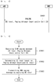
- FIG. 13 is a diagram exemplifying a network trigger service request procedure in a wireless communication system to which the present invention can be applied.
- the eNB/RNC calculates a paging occasion using an IMSI value and a DRX cycle of UE and transmits the paging message on the corresponding paging occasion.
- the MME may regard it as paging transmission failure and command a Paging retransmission to the eNB/RNC (or BSC) or cells.
- the Paging retransmission is determined in case that the Service request of UE is not received at the MME, and the eNB does not supervise whether the paging is received or retransmit.
- the MME transmits the paging to a great many cells
- the eNB may determine that the corresponding UE is not existed in its cell.
- the MME/SGSN in case that the MME/SGSN is unable to receive a response from the UE even after the paging repetition/retransmission procedure, the MME/SGSN notifies Paging failure to the S-GW using a downlink data notification reject message.
- the S-GW may delete packet(s) which is buffered.
- the paging procedure is used in order to transmit paging information to a UE in RRC_IDLE mode in network, or to notify change of system information to a UE in RRC_IDLE/RRC_CONNECTED mode, or to notify ETWS primary notification and/or ETWS secondary notification to all UEs in RRC_IDLE/RRC_CONNECTED mode, or to notify CMAS notification to a UE in RRC_IDLE/RRC_CONNECTED mode.
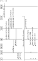
- FIG. 14 is a diagram exemplifying a paging procedure in a wireless communication system to which the present invention can be applied.
- an MME initiates a paging procedure by transmitting a paging message to an eNB (step, S1401).
- locations of UE in ECM-IDLE state is managed in the MME based on Tracking Area (TA).
- the MME may transmit a paging message to a plurality of eNBs that cover the cell belonged to the TA(s) where the UE is registered.
- each cell may be belonged to only one TA, and each eNB may include cells belonged to different TAs.
- the MME transmits a paging message to each eNB through S1AP interface (or S1AP protocol).
- S1AP interface or S1AP protocol
- this may be referred to 'S1AP paging message' (or paging request).
- the paging response replied to the MME is initiated in NAS layer, and the paging response may be transmitted by an eNB based on NAS-level routing information (step, S1402).
- the paging response may be corresponded to a service request NAS message transmitted from a UE.
- the service request NAS message may be transmitted to an eNB with being included in the RRC connection setup complete message, and may be transmitted to the MME with being included in the Initial UE message from the eNB.
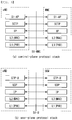
- Table 2 exemplifies the S1AP paging message.
- IE/Group Name Presence Range IE type and reference Semantic s description Criticality Assigne d Criticality Message Type M 9.2.1.1 YES ignore UE Identity Index value M 9.2.3.1 0 YES ignore UE Paging Identity M 9.2.3.1 3 YES ignore Paging DRX O 9.2.1.1 6 YES ignore CN Domain M 9.2.3.2 2 YES ignore List of TAIs 1 YES ignore >TAI List Item 1 .. ⁇ maxno ofTAIs > EACH ignore >>TAI M 9.2.3.1 6 - CSG Id List 0..1 GLOBAL ignore >CSG Id 1 .. ⁇ maxno ofCSGI d> 9.2.1.6 2 - Paging Priority O 9.2.1.7 8 YES ignore UE Radio Capability for Paging O 9.2.1.9 8 YES ignore
- IE/Group Name represents a name of an information element (IE) or an IE group.
- IE information element
- 'M' in the Presence field is a mandatory IE, and represents an IE/IE group included in a message always.
- 'O' is an optional IE and represents an IE/IE group included or may not be included in a message.
- 'C' is a conditional IE and represents an IE/IE group included in a message only when a specific condition is satisfied.
- the Range field represents a number of which repeated IEs/IE groups is available to be repeated.
- the IE type and reference field represents a type of the corresponding IE (e.g., ENUMERATED, INTEGER, OCTET STRING, etc.), and in case that a range of a value that the corresponding IE may have is existed, represents the range of the value.
- the Criticality field represents criticality information that is applied to an IE/IE group.
- the criticality information means information indicating how a reception terminal operates in case that the reception terminal does not understand all or a part of the IE/IE group.
- the sign, '-' represents that the criticality information is not applied, and the sign 'YES' represents the criticality information is applied.
- 'GLOBAL' represents that an IE and repeated IE have one piece of common criticality information.
- 'EACH' represents that each of repeated IE has unique criticality information.
- Assigned Criticality field represents actual criticality information.
- the information element (IE) or IE group included in the S1AP paging message will be described in more detail below.
- Message type IE identifies a message which is transmitted.
- PF Paging Frame
- UE Paging Identity IE is an identity for identifying a UE to be paged, and is indicated by one of SAE temporary mobile subscriber identity (S-TMSI).
- S-TMSI means an identity that is available to uniquely identify a UE among one MME group.
- S-TMSI is used as a UE paging identity.
- IMSI being used as a UE paging identity, this is paging with IMSI.
- the UE receives paging with the IMSI value, the UE performs a re-attach procedure.
- Paging DRX IE is used to calculate paging frame (PF) at an eNB.
- the UE may specify the DRX cycle length in the attach request message or tracking area update (TAU) message.
- CN Domain IE indicates whether the paging is generated in circuit switched (CS) domain or packet switched (PS) domain.
- TAI Tracking Area Identity
- List IE is used to notify a TA in which a paging message should be broadcasted to an eNB.
- the TAI means an identity which is used to uniquely identify TA.
- Closed Subscriber Group (CSG) ID List IE represents a CSG set where a UE is subscribed. This prevents an eNB from paging to a UE in a CSG cell where the UE is not subscribed.
- Paging Priority IE indicates a paging priority for paging UE.
- UE Radio Capability for Paging IE for paging includes paging-specific UE radio capability information.
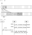
- the eNB that receives S1AP paging message from the MME configures a paging message (hereinafter, referred to 'RRC paging message' (or paging information)).
- 'RRC paging message' or paging information
- Table 3 exemplifies a RRC paging message.
- a single RRC paging message of UE may carry information of multiple S1AP paging messages. That is, the RRC paging message may include multiple paging records (e.g., 16) for paging multiple UEs.
- Each paging record includes a UE-Identity field and a CN domain field. This is a content which is transmitted from a S1AP paging message.
- the systemInfoModification field is not delivered from the S1AP paging message, but is generated by an eNB. This field is used for triggering such that a UE re-acquires a system information block (SIB) set.
- SIB system information block
- EAB-ParamModification field is used to indicate change of EAB parameter (SIB 14).
- the ETWS-Indication field is not delivered from the S1AP paging message, but is generated by an eNB. This field is applied only to an ETWS capable UE, and is used to trigger such that the corresponding UE re-acquires SIB 1.
- the SIB 1 content indicates ETWS content in SIB 10 and SIB 11 to a UE.
- the CMAS-Indication field is applied only to a CMAS capable UE, and is used to trigger such that the corresponding UE re-acquires SIB 1.
- the SIB 1 content indicates CMAS content in SIB 12 to a UE.
- the eNB that configures the RRC paging message transmits downlink control information (DCI) where cyclic redundancy check (CRC) which is scrambled to paging-RNTI (P-RNTI) to a UE in the PDCCH, and transmits the RRC paging message to the UE through the PDSCH.
- DCI downlink control information
- CRC cyclic redundancy check
- P-RNTI paging-RNTI
- an eNB delivers the RRC paging message through the PCCH logical channel, the PCH transport channel and the PDSCH physical channel to a UE.
- the eNB determines a PDCCH format according to the DCI that will be sent to the UE, and attaches CRC to the DCI.
- a unique radio network temporary identifier (RNTI) is scrambled (or masked) to CRC.
- RNTI radio network temporary identifier
- a unique identity of UE e.g., cell-RNTI; C-RNTI
- a paging indication identity e.g., paging-RNTI; P-RNTI
- P-RNTI paging indication identity
- a UE monitors the PDCCH based on P-RNTI in a subframe belonged to its paging occasion. And if the UE detects the PDCCH masked by P-RNTI, the UE decodes the DCI transmitted on the PDCCH. The DCI indicates the PDSCH resource where the paging message is transmitted. And the UE decodes the RRC paging message from the PDSCH resource indicated in the DCI.
- the paging cycle may be determined in a cell-specific manner, or determined in a UE-specific manner.
- the paging occasion is determined based on its paging cycle and its identity (i.e., IMSI) for each UE. Accordingly, the paging message is not transmitted to all UEs on an available paging occasion from an eNB, but the paging message is transmitted on the paging occasion of the corresponding UE.
- IMSI identity
- the paging procedure may be used for change of system information, reception of cell broadcast message (i.e., ETWS/CAMS warning message) and notification of EAB as well as notifying reception of individual UE's Mobile Terminated (MT) call.
- ETWS/CAMS warning message i.e., ETWS/CAMS warning message
- MT Mobile Terminated
- a UE identity e.g., IMSI or S-TMSI
- the UE in RRC_IDLE mode initiates a random access procedure for establishing RRC connection (e.g., transmitting service request) with network.
- system information modification (systemInfoModification) is included in the RRC paging message
- a UE re-acquires the system information which is required by using a system information acquisition procedure.
- the UE re-acquires SIB 1 immediately. That is, the UE does not wait for the boundary of the next system information modification cycle. And if the scheduling information list (schedulingInfoList) included in SIB 1 indicates that SIB 10 is existed, the UE acquires SIB 10 based on the scheduling information (schedulingInfor). In addition, if the scheduling information list (schedulingInfoList) included in SIB 1 indicates that SIB 11 is existed, the UE acquires SIB 11 based on the scheduling information (schedulingInfor).
- CMAS indication (cmas-Indication) is included in the RRC paging message and a UE supports CMAS, the UE re-acquires SIB 1 immediately. That is, the UE does not wait for the boundary of the next system information modification cycle. And if the scheduling information list (schedulingInfoList) included in SIB 1 indicates that SIB 12 is existed, the UE acquires SIB 12 based on the scheduling information (schedulingInfor).
- a UE receives SIB 10, SIB 11 and SIB 12 by referring to schedulingInfoList of SIB 1.
- the received SIB 10, SIB 11 and SIB 12 are delivered to a higher layer (e.g., RRC layer) of UE.
- the UE displays the message identifier included in the cell broadcast message which is delivered through SIB 10, SIB 11 and SIB 12 if the message identifier is included in a search list of the UE. And otherwise, the UE discard it.
- the UE regards SIB 14 which is stored before is not valid, and re-acquires SIB 1 immediately. That is, the UE does not wait for the boundary of the next system information modification cycle. And the UE re-acquires SIB 14 using the system information acquisition procedure.
- 3GPP LTE/LTE-A system defines discontinuous reception (DRX) technique of UE in order to minimize the power consumption of UE.
- DRX discontinuous reception
- a UE that uses the DRX monitors whether a paging message is transmitted only one paging occasion for every Paging cycle (i.e., DRX cycle).
- One Paging Frame means one radio frame that may include one or more paging occasion(s).
- One paging occasion means one subframe where the P-RNTI transmitted on the PDCCH that addresses a paging message may be existed. That is, the paging occasion is defined as a specific subframe in a PF that a UE checks a paging message.
- the PF and the PO are determined by using IMSI and DRX values of UE.
- the UE may calculate the PF and the PO using its IMSI and DRX values.
- an eNB may also calculate the PF and the PO for each UE through the IMSI value which is delivered from the MME.
- the DRX parameter (i.e., paging/PCCH configuration information) may be transmitted with being included in a common radio resource configuration ('RadioResourceConfigCommon') IE which is a RRC message used for specifying common radio resource configurations.
- the common radio resource configuration IE may be transmitted through a RRC message such as a RRC connection reconfiguration message or an S1 message.
- the S1 message is a message which is used for transmitting one or more SIBs.
- a UE may also request its DRX cycle through an attach request or a tracking area update (TAU) request message.
- TAU tracking area update
- a DRX cycle length set that the UE may request is identical to the length set which is used in the system information.
- Table 4 exemplifies the PCCH configuration information in the common radio resource configuration IE. [Table 4]
- the PCCH configuration information includes the 'defaultPagingCycle' field that indicates a default paging cycle length and the parameter 'nB' for acquiring the paging frame and the paging occasion.
- the 'defaultPagingCycle' field has a default paging cycle length, and setup as one value of ⁇ rf32, rf64, rf128, rf256 ⁇ .
- the rf means radio frame
- 'T' represents a DRX cycle of UE.
- 'T' is determined to the smallest value among a UE-specific DRX cycle and the basic DRX cycle ('defaultPagingCycle' field value) which is broadcasted in the system information.
- 'T' is determined to the default DRX cycle.
- the PF is determined according to Equation 1 below.
- SFN mod T T div N * UE_ID mod N
- a UE does not monitor all subframes of the PF which is determined as above, but monitors only the subframe which is distinguished by the PO determined by Equation 2 below and Table 5 (or Table 6).
- i_s floor UE_ID / N mod Ns
- Ns represents max(1, nB/T).
- Table 6 exemplifies a subframe pattern for determining the PO in TDD.
- the subframe index that corresponds to the PO is determined. That is, a UE monitors only the subframe that corresponds to the PO in the PF which is determined.
- An S1 release procedure is used for releasing logical S1-AP signaling connection (through S1-MME) for UE and all S1 bearers (in S1-U).
- This procedure changes UE state from an ECM-CONNECTED state to an ECM-IDLE state, and all UE related context information in an eNB are deleted. For example, when S1-AP signaling connection is lost owing to loss of signaling transmission or to failure of an eNB or MME, the S1 release procedure is locally performed by the eNB or the MME. When the S1 release procedure is locally performed by the eNB or the MME, each node locally performs the operations according to the flow of procedure shown in FIG. 15 below.
- Start of the S1 release procedure is on any one of the followings.
- FIG. 15 is a diagram exemplifying an S1 release procedure in a wireless communication system to which the present invention can be applied.
- both of the eNB-initiation and the MME-initiation are exemplified.
- the MME deletes eNB-related information ("eNB address used for S1-MME", "MME UE S1 AP ID” and "eNB UE S1AP ID”) from the MME context. However, the MME maintains the remaining information of the MME context of UE including the S1-U configuration information (address and TEID) of S-GW. All non-guaranteed beat ratio (non-GBR) EPS bearers which are established for the corresponding UE are preserved in the MME and the S-GW.
- eNB address used for S1-MME "MME UE S1 AP ID”
- eNB UE S1AP ID eNB UE S1AP ID
- the MME preserves the GBR bearers. If the cause of S1 release is due to CS fallback trigger, a procedure for bearer handling may be performed. Otherwise (e.g., in case that radio connection with UE is disconnected, S1 signaling connection is disconnected, eNB failure, etc.), the MME triggers an MME initiated dedicated bearer deactivation procedure for GBR bearers of UE after the S1 release procedure is completed.
- LIPA local IP access
- HeNB home eNB
- L-GW collocated local gateway
- the coverage enhancement means operations for supporting such that a UE is available to receive data successfully in a coverage enhancement level (CE level) by transmitting the same data (or signal/channel) repeatedly according to the CE level (e.g., 0dB, 6dB, 12dB and 18dB) that the corresponding UE requires, considering the case that a UE (e.g., UE for M2M use, low complexity UE, MTC UE, etc.) supporting the coverage enhancement is located in a shadow area (e.g., buried under the ground, underground, etc.) or cell edge. That is, the UE in the enhanced coverage means a UE that requires use of the enhanced coverage functionality in order to access a cell.
- CE level e.g., 0dB, 6dB, 12dB and 18dB
- the UE may access cell by using the enhanced coverage functionality. Otherwise, the UE may determine that access to cell is barred.
- system information e.g., master information block (MIB)
- a UE in the enhanced coverage receives a system information block (SIB) transmitted using different time/frequency resources in comparison with normal UE.
- SIB system information block
- a UE in the enhanced coverage may have a limited transport block size (TBS; e.g., 1000 bits) for broadcasting and unicasting.
- TBS transport block size
- a UE in the enhanced coverage determines scheduling information for SIB1 which is specified for the UE in the enhanced coverage based on information in a Master Information Block (MIB).
- MIB Master Information Block
- the scheduling information for other SIB is given in SIB 1 which is specified for the UE in the enhanced coverage.
- a BCCH modification cycle for a UE in the enhanced coverage may correspond to a multiple of the BCCH modification cycle provided in SIB2.
- SIB1 system information
- SIB1 system information
- a UE in the enhanced coverage may acquire an S1 message in S1 window.
- the maximum count (e.g., 4) of the SI message that may be acquired in the S1 window may be fixed.
- a UE in the enhanced coverage may use or acquire legacy system information when it is in a normal coverage.
- a UE in the enhanced coverage is not required to detect change of SIB when it is in RRC_CONNECTED state.
- a UE in RRC_IDLE state does not notify change of CE level to network.
- FIG. 16 is a diagram exemplifying coverage enhancement operations in a wireless communication system to which the present invention can be applied.
- a UE may aggregate the data which are repeatedly received, and owing to this, successful data transmission of UE located in a shaded area is available.
- an example of the single data may be correspond to random access preamble, random access response, paging message, (E)PDCCH, PUSCH, PDSCH, and so on.
- the CE level may be defined by whether the UE/eNB is required to perform repetition for transmitting a certain single data (or signal/channel) (1601) for successful UL/DL transmission/reception.
- CE level 0 may indicate the repetition is not needed
- CE level 1 may indicate the repetition is needed
- the CE level may be defined by the (maximum) number of times of repetition (or the (maximum) amount of repetition, for example, resource blocks, subframes) for transmitting a certain single data (or signal/channel) (1601) required for successful UL/DL transmission/reception.
- CE level 0 indicates that the repetition is not needed
- CE level 1 indicates that the repetition is needed by some number of times (or some amount)
- CE level 2 indicates that the repetition is needed by more number of times (or more amount) than that needed for CE level 1, and so on.
- the number of times of repetition (or repetition amount) for transmitting a single data (or signal/channel) according to the CE level may be determined for each eNB.
- the CE level may be predefined by N levels. And number of times of repetition (or repetition amount) of the single data (or signal/channel) (1601) may be determined (or predefined) for each CE level.
- maximum number of times of repetition (or maximum amount of repetition) of the single data (or signal/channel) (1601) may be determined (or predefined) for each CE level.
- the eNB may determine actual number of times of repetition (or amount of repetition) within maximum number of times of repetition (or maximum amount of repetition).
- a decibel may be used as a unit of CE level (e.g., 0dB, 6dB, 12dB, 18dB, etc).
- the single data (or signal/channel) may be transmitted once in case of CE level 0dB (i.e., no repetition), the single data (or signal/channel) may be transmitted repeatedly by some number of times (or some amount) in case of CE level 6dB, the single data (or signal/channel) may be transmitted repeatedly by more number of times (or more amount) than that needed for CE level 6dB in case of CE level 12dB, and the single data (or signal/channel) may be transmitted repeatedly by more number of times (or more amount) than that needed for CE level 12dB in case of CE level 18dB.
- an eNB In case that a UE requires the coverage enhancement, an eNB should be aware of this and transmit downlink data (or signal/channel) which is fit to the CE level that the UE requires.
- the coverage enhancement is defined as 4 levels of 0dB, 6dB, 12dB and 18dB, it is the most efficient that an eNB transmits downlink data in a format (i.e., repetition count (or repetition amount) that corresponds to the CE level of UE) corresponding to the coverage enhancement that a UE requires.
- a format i.e., repetition count (or repetition amount) that corresponds to the CE level of UE
- an eNB should use more radio resources due to the repeated transmission.
- inefficient power consumption for UE is anticipated due to repeated reception of unnecessary downlink data and decoding.
- an eNB since the paging procedure is an operation performed in an idle mode by a UE, an eNB simply forwards S1AP paging message which is received from an MME to a UE. Accordingly, the eNB is unable to transmit by considering physical properties of individual UE.
- the subscriber information e.g., the subscription information stored in HLR/HSS
- whether the corresponding UE is Rel-13 low complexity UE e.g., MTC UE, etc.
- the eNB may transmit a RRC paging message by considering the coverage enhancement of the biggest CE level (i.e., transmitting the RRC paging message as many as the maximum repetition count), but this may cause unnecessary consumption of radio resources.
- the present invention proposes a method for increasing paging reception efficiency of UE that supports the coverage enhancement (or the coverage enhancement is applied) and for decreasing unnecessary consumption of radio resources in an eNB.
- the present invention proposes a method for providing paging transmission count and/or CE level information of UE to an eNB by an MME during the paging procedure such that the eNB may transmit a RRC paging message according to the CE level of UE.
- the present invention proposes a method for transmitting paging to a UE according to the CE level which is determined based on the paging transmission count and/or CE level information received from an MME by an eNB.
- the meaning of ramping-up a CE level may be interpreted as a meaning of increasing the CE level value itself, but also interpreted as meaning of increasing a repetition count of paging message according to the CE level in order to increase reception gain of paging in a UE, not the CE level value itself.
- Each coverage enhancement level (CE level) and the related PRACH resource set (e.g., time resource, frequency resource and preamble; i.e., PRACH configuration) are provided in an SIB.
- PRACH repetition count and maximum preamble transmission trial count per CE level are provided in the SIB.
- a UE may select the PRACH resources (e.g., time resource, frequency resource and preamble) that correspond to a CE level which is proper to its reception sensitivity (e.g., RSRP, etc.) by reading the SIB and PRACH resource information. That is, an initial CE level of UE is selected by the UE.
- PRACH resources e.g., time resource, frequency resource and preamble
- reception sensitivity e.g., RSRP, etc.
- the UE transmits the PRACH to an eNB by using the selected PRACH resource.
- the eNB may know the initial CE level of the corresponding UE from the PRACH configuration.
- the UE transmits PRACH in the next higher (or lower) CE level.
- the UE in an identical CE level uses a random access resource related to the identical CE level.
- the time/frequency resource and repetition factor of the random access response message for the UE in the enhanced coverage is derived from the used PRACH resources.
- the CE level of UE may be changed according to movement of UE, and the eNB may determine the CE level of UE by the change of CE level of UE. And the eNB may notify information such as a repetition count of data (or signal/channel) according to the CE level using DCI, and so on.
- the CE level value of UE may be transmitted to an MME during an S1 release procedure.
- an IDLE e.g., RRC_IDLE/ECM-IDLE
- a CONNECTED mode e.g., RRC_CONNECTED/ECM-CONNECTED
- an eNB may notify the CE level value of UE to an MME on the S1 release. For example, the eNB provides the CE level that a UE used most recently to the MME. And while the MME stores the CE level received from the eNB in the context information of UE, the MME may transmit an S1AP paging message (or paging request) for the corresponding UE with the stored CE level to the eNB. This will be described by reference to the drawing below.
- FIG. 17 is a drawing exemplifying an S1 release procedure for determining a coverage enhancement level in a paging procedure according to an embodiment of the present invention.
- the S1 release procedure according to the present invention includes both of eNB-initiated and MME-initiated S1 release procedures like the description according to FIG. 15 .
- the parts which are different from the example of FIG. 15 will be mainly described for the convenience of description below.
- an eNB transmits a UE context release request message to an MME (through S1-AP protocol) (step, S1701).
- the UE context release request message is a message transmitted by the eNB in order to request release of S1-logical connection which is UE-associated through the S1 interface.
- the eNB may transmit a RRC connection release message to a UE in order to release signaling connection of UE before transmitting the UE context release request message to the MME or with the transmission. That is, step S1703 may be performed before or with step S1701.
- step S1701 may be performed only in case that the eNB-initiated S1 release procedure is considered, and may not be performed in case that the MME-initiated S1 release procedure is performed.
- the MME transmits a UE context release command message to the eNB (through S1-AP protocol).
- the eNB may transmit a RRC connection release message to the UE (step, S1703).
- the eNB transmits a UE context release complete message to the MME (through S1-AP protocol) in response to the UE context release command message (step, S1704).
- the UE context release command message is a message which is transmitted by the eNB in order to confirm the release of UE-associated S1-logical connection through S1 interface.
- the UE context release complete message may include CE level information.
- the UE context release complete message may include CE level and cell ID (e.g., ECGI). That is, the eNB may forward the CE level to the MME for each cell.
- CE level e.g., ECGI
- the CE level of UE may be transmitted with being included in the S1-AP UE context release complete message (i.e., step S1704).
- the CE level of UE may also be transmitted with being included in the S1-AP UE context release request message (i.e., step S1701) to the MME.
- the CE level which is transmitted to the MME may be corresponded to the CE level which is used most recently before the S1 release procedure. This may be interpreted to the CE level which is lastly used in the CONNECTED mode of UE or most recently used before being switched from the CONNECTED mode to the IDLE mode.
- the UE/eNB transmits uplink/downlink data using a specific CE level and is unable to receive the response to it, the UE/eNB retransmits the uplink/downlink data by ramping CE level. Accordingly, the CE level may be interpreted as the CE level of being successfully used most recently.
- the eNB may forward the CE level of UE to the MME when performing an S1 release procedure, and the MME may notify this again so as to use the corresponding CE level (i.e., the CE level which is received when performing S1 release) in the eNB when paging for the corresponding UE.
- the MME may forward the CE level to the eNB when transmitting paging to the corresponding cell by storing the cell ID (e.g., ECGI).
- Table 7 exemplifies the UE context release request message.
- the Message Type IE uniquely identifies a message which is transmitted.
- the MME UE S1AP ID IE identifies a UE association through S1 interface in the MME.
- the eNB UE S1AP ID IE identifies a UE association through S1 interface in the eNB.
- the cause IE indicates a cause of a specific event for S1AP protocol. That is, the cause IE indicates a cause of transmitting a UE context release request message.
- the GW context release Indication IE is set by the eNB in order to provide an instruction of which resources related to S1 UE context where the MME is signaled is to be released.
- the UE coverage enhancement level IE indicates a CE level of UE.
- the UE coverage enhancement level IE is included in a UE context release request message, this may correspond to the CE level which is used most recently before the S1 release procedure.
- Table. 8 exemplifies the UE coverage enhancement level IE.
- UE Coverage Enhancement level M ENUMERATED (CE level1, CElevel2, CElevel3...
- the UE coverage enhancement level IE indicates a CE level of UE.
- the UE coverage enhancement level IE may include ENUMERATED type (CElevel1, CElevel2, CElevel3, etc.). And the UE coverage enhancement level IE may indicate any one of N CE levels which are predefined (or preconfigured). For example, the UE coverage enhancement level IE may indicates one of CElevel1, CElevel2, CElevel3, and so on.
- Table 9 exemplifies a UE context release complete message.
- Table 9 *IE/Group Name Presen ce Range IE type and referen ce Semanti CS descrip tion Critic ality Assign ed Critic ality Message Type M 9.2.1.1 YES reject MME UE S1AP ID M 9.2.3.3 YES ignore eNB UE S1AP ID M 9.2.3.4 YES ignore Criticality Diagnostics O 9.2.1.2 1 YES ignore User Location Information O 9.2.1.9 3 YES ignore UE Coverage Enhancement level O 9.2.1.X X YES ignore
- the Criticality Diagnostics IE is transmitted by the eNB or the MME.
- this IE includes information on which IE is not comprehended or lost.
- the User Location Information IE provides location information of UE.
- the UE coverage enhancement level IE indicates a CE level of UE.
- the UE coverage enhancement level IE is included in the UE context release complete message, this may correspond to the CE level which is used most recently before the S1 release procedure.
- the UE coverage enhancement level IE may indicate any one of N CE levels which are predefined (or preconfigured) similar to those of Table 8 above.
- the MME may store the CE level which is received through a UE context release complete message (or a UE context release request message) from the eNB, and use the CE level for the next paging.
- the MME may check forwarding the CE level when transmitting paging to the corresponding cell by storing a cell identity (e.g., ECGI) when storing the CE level in UE context information.
- a cell identity e.g., ECGI
- An MME stores a CE level which is received from an eNB through the S1 release procedure described above in context information of UE. And the MME may transmit a S1AP paging message with a paging count and/or a CE level being included in order to increase transmission efficiency of paging when transmitting the S1AP paging message for the corresponding UE. This will be described by reference to the drawing below.
- FIG. 18 is a diagram exemplifying a paging transmission method according to an embodiment of the present invention.
- an MME transmits a S1AP paging message (or paging request) to an eNB (step, S1801).
- the S1AP paging message may include a CE level of UE, paging transmission count (or paging attempt count) and/or a cell identity (cell ID; e.g., ECGI, etc.).
- cell ID e.g., ECGI, etc.
- the MME may retransmit a CE level by ramping-up the previous CE level. That is, when retransmitting paging, the MME may retransmit the S1AP paging message (or paging request) with a higher CE level than the CE level included in the previous paging message (or paging request) being included.
- the MME may transmit an S1AP paging message (or paging request) with a CE level by ramping-up the CE level which is transmitted with an initial S1AP paging message (or paging request) to the eNB.
- the MME may transmit an S1AP paging message (or paging request) with a CE level by ramping-up the CE level which is transmitted with the second S1AP paging message (or paging request) to the eNB.
- a method of transmitting a CE level by ramping-up the previous value by the MME may be used when retransmitting paging.
- the MME may transmit a S1AP paging message with the CE level being included when transmitting paging of the corresponding UE. And when retransmitting paging, the already stored CE level may be used as a default value and also used by ramping-up the default CE level. That is, the CE level included in the S1AP paging message may be a CE level received (through S1 UE Context Release Complete during an S1 release procedure) from the last eNB to which the UE was connected.
- the MME may store a CE level which is received from the eNB during the S1 release procedure for a specific UE, and transmit an initial S1AP paging message (or paging request) with the stored CE level being included for the corresponding UE. And when retransmitting the S1AP paging message (or paging request) for the corresponding UE, as described above, the MME may transmit the S1AP paging message with a CE level by ramping-up the previous CE level.
- the CE level may be started from a predetermined CE level value (e.g., one of the lowest CE level value, the highest CE level value, medium value or an average value). That is, when transmitting an initial S1AP paging message to a specific UE, in case that total N CE levels are predefined (or preconfigured), the MME may transmit the predetermined CE level with being included in the S1AP paging message. And when retransmitting the S1AP paging message to the corresponding UE, the MME may transmit the S1AP paging message with the CE level by ramping-up the previous CE level being included.
- a predetermined CE level value e.g., one of the lowest CE level value, the highest CE level value, medium value or an average value.
- the MME may transmit the S1AP paging message with the CE level being included only in case of transmitting paging to the eNB (or cell) that provides the CE level of the corresponding UE.
- Table 10 exemplifies an S1AP paging message according to an embodiment of the present invention.
- Table 10 IE/Group Name Presence Range IE type and reference Semanti CS description Criticality Assigned Criticality Message Type M 9.2.1.1 YES ignore UE Identity Index value M 9.2.3.1 0 YES ignore UE Paging Identity M 9.2.3.1 3 YES ignore Paging DRX O 9.2.1.1 6 YES ignore CN Domain M 9.2.3.2 2 YES ignore List of TAIs 1 YES ignore >TAI List Item 1 .. ⁇ maxnoof TAIs> EACH ignore >>TAI M 9.2.3.1 6 - CSG Id List 0..1 GLOBAL ignore >CSG Id 1 ..
- the S1AP paging message may include the UE coverage enhancement level IE.
- the UE coverage enhancement level IE may also be included in the UE Radio Capability for Paging IE.
- Table 11 exemplifies the UE coverage enhancement level IE according to an embodiment of the present invention.
- UE Coverage Enhancement level M ENUMERATED (CE level1, CElevel2, CElevel3...
- the UE coverage enhancement level IE may indicate UE coverage enhancement levels (e.g., CElevel1, CElevel2, CElevel3, etc.) for paging by an eNB.
- UE coverage enhancement levels e.g., CElevel1, CElevel2, CElevel3, etc.
- the MME when the MME transmits an initial S1AP paging message to a specific UE, the MME indicate '1' as the paging attempt count (or paging transmission count) included in the S1AP paging message. And when the MME transmits the second S1AP paging message to the corresponding UE, the MME may indicate '2' as the paging attempt count (or paging transmission count) included in the S1AP paging message.
- Table 12 exemplifies an S1AP paging message according to an embodiment of the present invention.
- IE/Group Name Presence Range IE type and reference Semantics description Criticality Assign ed Criticality Message Type M 9.2.1.1 YES ignore UE Identity Index value M 9.2.3.1 0 YES ignore UE Paging Identity M 9.2.3.1 3 YES ignore Paging DRX O 9.2.1.1 6 YES ignore CN Domain M 9.2.3.2 2 YES ignore List of TAIs 1 YES ignore >TAI List Item 1 .. ⁇ maxnoof TAIs> EACH ignore >>TAI M 9.2.3.1 6 - CSG Id List 0..1 GLOBAL ignore >CSG Id 1 .. ⁇ maxnoof CSGId> 9.2.1.6 2 - Paging Priority O 9.2.1.7 8 YES ignore UE Radio Capability for Paging O 9.2.1.9 8 YES ignore Paging Count O 9.2.1.X X YES ignore IE/Group Name Presence Range
- the S1AP paging message may include a paging count (or paging attempt count) IE.
- Table 13 exemplifies the paging count IE according to an embodiment of the present invention.
- IE/Group Name Presence Range IE type and reference Semantics description Paging count M ENUMERATED (0, 1, 2 , 3...
- the paging count IE indicates count (0, 1, 2, 3, etc.) of paging retransmission trial (or attempt).
- the UE may move in IDLE duration, so the CE level may vary due to the mobility of the UE.
- MME may transmit the S1AP paging message including the CE level before changing to the eNB.
- the eNB transmits the RRC paging message using inappropriate CE level to the UE.
- the UE moves the area which is required higher CE level due to the mobility of UE, paging failure may occur owing to lower paging repetition.
- the eNB doesn't manage the history for transmitting the paging for each UE, the eNB cannot be aware of whether paging retransmission is required.
- the eNB cannot perform appropriate action (e.g., retransmission RRC paging message using higher CE level), and the paging failure may occur repeatedly.
- the MME may inform the paging attempt count to the eNB, so that the eNB can determine whether the CE level of the corresponding UE is appropriate. Further, the eNB can determine whether to ramp up the CE level of the corresponding UE autonomously (i.e., ramping up the CE level according to higher paging attempt count), the possibility of paging failure can be decreased.
- an S1AP paging message may include a paging attempt count (or paging transmission count) together with a CE level. That is, embodiment 1) and embodiment 2) described above may be applied together.
- the MME may transmit a S1AP paging message with the CE level being included when transmitting paging of the corresponding UE.
- the already stored CE level may be used as a default value and also used by ramping-up the default CE level.
- the MME may store a CE level which is received from the eNB during the S1 release procedure for a specific UE, and transmit an initial S1AP paging message (or paging request) with the stored CE level being included for the corresponding UE.
- the MME may transmit a ramping-up the previous CE level.
- the CE level may be started from a value (e.g., in case that total N CE levels are predefined (or preconfigured), one of medium value, an average value, the lowest CE level value or the highest CE level value of N CE levels which are predefined (or preconfigured)) which is determined by the MME. That is, when transmitting an initial S1AP paging message to a specific UE, in case that total N CE levels are predefined (or preconfigured), the MME may transmit the S1AP paging message with the CE level which is determined by the MME. And when retransmitting the S1AP paging message to the corresponding UE, the MME may transmit the S1AP paging message with the CE level by ramping-up the previous CE level being included.
- a value e.g., in case that total N CE levels are predefined (or preconfigured), one of medium value, an average value, the lowest CE level value or the highest CE level value of N CE levels which are predefined (or preconfigured) which is determined by
- the MME may transmit the S1AP paging message with the CE level being included only in case of transmitting paging to the eNB (or cell) that provides the CE level of the corresponding UE. That is, when performing S1 release, only paging transmission count (or paging attempt count) without CE level may be transmitted to an eNB except the eNB that provides the CE level of the corresponding UE.
- Table 14 exemplifies an S1AP paging message according to an embodiment of the present invention.
- IE/Group Name Presence Range IE type and reference Semantics description Criticality Assigned Criticality Message Type M 9.2.1.1 YES ignore UE Identity Index value M 9.2.3.1 0 YES ignore UE Paging Identity M 9.2.3.1 3 YES ignore Paging DRX O 9.2.1.1 6 YES ignore CN Domain M 9.2.3.2 2 YES ignore List of TAIs 1 YES ignore >TAI List Item 1 .. ⁇ maxnoof TAIs> EACH ignore >>TAI M 9.2.3.1 6 - CSG Id List 0..1 GLOBAL ignore >CSG Id 1 ..
- the S1AP paging message may include the UE coverage enhancement level IE and the paging count (or paging attempt count) IE.
- the UE coverage enhancement level IE may be included in the UE radio capability for Paging IE.
- Table 15 exemplifies the UE coverage enhancement level IE according to an embodiment of the present invention.
- UE Coverage Enhancement level M ENUMERATED (CE level1, CElevel2, CElevel3...
- the UE coverage enhancement level IE may indicate a UE coverage enhancement level (CE level; e.g., CElevel1, CElevel2, CElevel3, etc.) for paging by an eNB.
- CE level e.g., CElevel1, CElevel2, CElevel3, etc.
- Table 16 exemplifies the paging count IE according to an embodiment of the present invention.
- IE/Group Name Presence Range IE type and reference Semantics description Paging count M ENUMERATED (0, 1, 2, 3...
- the paging count IE indicates a paging trial (or attempt) count (0, 1, 2, 3, etc.).
- the first S1AP paging message (or paging request) may include the paging transmission count (or paging attempt count) together with the CE level, but the retransmitted S1AP paging message (or paging request) may include only the paging transmission count (or paging attempt count).
- the MME may transmit an initial S1AP paging message with the CE level being included when transmitting the paging of the corresponding UE. That is, an MME may store a CE level received from an eNB during an S1 release procedure for a specific UE, then transmit an initial S1AP paging message (or paging request) for the corresponding UE with the stored CE level being included.
- the CE level may correspond to a value (e.g., in case that total N CE levels are predefined (or preconfigured), one of medium value, an average value, the lowest CE level value or the highest CE level value of N CE levels which are predefined (or preconfigured)) which is determined by the MME. That is, when transmitting an initial S1AP paging message to a specific UE, the MME may transmit an initial S1AP paging message with the CE level which is determined by the MME.
- the MME may transmit the S1AP paging message with the CE level being included only in case of transmitting paging to the eNB (or cell) that provides the CE level of the corresponding UE. That is, when performing S1 release, only paging transmission count (or paging attempt count) without CE level may be transmitted to an eNB except the eNB that provides the CE level of the corresponding UE.
- an initial S1AP paging message may be configured as Table 14, and the S1AP paging message which is retransmitted later may be configured as Table 12.
- FIG. 19 is a diagram exemplifying a paging transmission method according to an embodiment of the present invention.
- an eNB receives an S1AP paging message (or paging request) from an MME (step, S1901).
- the S1AP paging message may include a CE level of UE, paging transmission count (or paging attempt count) and/or a cell identity (e.g., ECGI, etc.).
- a CE level of UE paging transmission count (or paging attempt count)
- a cell identity e.g., ECGI, etc.
- the eNB determines a CE level of the corresponding UE based on the paging transmission count (or paging attempt count) and/or the CE level of UE (step, S1902).
- the eNB transmits a RRC paging message (or paging information) to the corresponding UE by applying the CE level which is determined (step, S1903).
- the eNB setup the RRC paging message (refer to Table 3 above), transmits a DCI to which a CRC which is scrambled by P-RNTI in a PDCCH, and transmits the RRC paging message to the UE through a PDSCH which is indicated by the PDCCH. That is, the eNB transmits the RRC paging message through a PCCH logical channel, a PCH transmission channel and a PDSCH physical channel.
- the eNB may transmit the RRC paging message to the corresponding UE on a paging occasion of the corresponding paged UE which is determined by using IMSI and DRX values of the paged UE.
- the eNB when the eNB transmits a RRC paging message (or paging information) to a UE using the received paging transmission count (or paging attempt count), the eNB may apply a CE level to the corresponding UE for paging in various ways.
- an initial CE level may be determined for each eNB.
- each of the eNB may individually determine an initial CE level for paging to each cell that the eNB serves.
- the eNB may determine a CE level as one of medium value, an average value or the lowest value among N CE levels which are predefined (or preconfigured).
- the eNB may determine an initial CE level based on (considering) paging resources and/or a number of UE (i.e., paging queue) to which the RRC paging message is transmitted, and so on.
- a paging occasion may be determined for each UE by using IMSI and DRX values of the UE. And the eNB may transmit the RRC paging message to the corresponding UE on a paging occasion of the paged UE.
- the maximum number i.e., the maximum number or paging resource of UE that is available to be paged
- the maximum number of a paging record that may be included in a single RRC paging message that the eNB transmits may be predefined.
- the eNB that receives an S1AP paging message from an MME may determine an initial CE level for paging based on paging resources and/or a number of UE to which paging will be transmitted, and so on. And the eNB transmits a RRC paging message on the paging occasion of the corresponding UE by applying the initial CE level which is determined by the eNB.
- the eNB may determine a CE level for paging by ramping-up the initial CE level depending on the paging attempt count (or paging transmission count) included in the S1AP paging message. For example, if the paging attempt count (or paging transmission count) is 2, the eNB may determine a CE level by ramping-up the initial CE level by one step.
- the eNB may transmit a RRC paging message to a UE by applying a CE level included in the S1AP paging message.
- the eNB may transmit a RRC paging message to a UE by applying a CE level by ramping-up (for example, by one step) the CE level included in the corresponding S1AP paging message.
- the (maximum) number of times of repetition (or the (maximum) amount of repetition) of RRC paging message corresponding to the CE level 0 (e.g., 0dB), CE level 1 (e.g., 6dB), CE level 2 (e.g., 12dB) and CE level 3 (e.g., 18dB) are 1, 2, 3 and 4 times (or resource blocks, subframes) respectively.
- the eNB may transmit the RRC paging message to the corresponding UE at (maximum) 3 times (or (maximum) 3 resource blocks or (maximum) 3 subframes) corresponding to CE level 2 (ramping up the CE level 1 by one step) repeatedly.
- the eNB may transmit the RRC paging message to the corresponding UE at (maximum) 2 times (or (maximum) 2 resource blocks or (maximum) 2 subframes) corresponding to the received CE level 1 repeatedly regardless the paging attempt count.
- the eNB may transmit a RRC paging message to a UE by applying a CE level by ramping-up (for example, by two steps) the CE level included in the corresponding S1AP paging message.
- the eNB may transmit the RRC paging message to the corresponding UE at (maximum) 4 times (or (maximum) 4 resource blocks, (maximum) 4 subframes) corresponding to CE level 3 repeatedly.
- the eNB may transmit the RRC paging message to the corresponding UE at (maximum) 2 times (or (maximum) 2 resource blocks, (maximum) 2 subframes) corresponding to the received CE level 1 repeatedly regardless the paging attempt count.
- the MME may retransmit a CE level by ramping-up the previous CE level.
- an MME may transmit the initial S1AP paging message with an initial CE level, and when retransmitting the S1AP paging message to the same UE, the MME may transmit the S1AP paging message with a CE level by ramping-up the initial CE level.
- the S1AP paging message (or paging request) may include paging attempt count (or paging transmission count; e.g., 1, 2, 3, etc.).
- the eNB may transmit a RRC paging message (or paging information) by applying the CE level received from the MME.
- the eNB may apply its maximum CE level.
- the eNB may transmit a RRC paging message to a UE by applying a CE level included in the S1AP paging message.
- the eNB may transmit a RRC paging message to a UE by applying a CE level by ramping-up the CE level included in the corresponding S1AP paging message of which the paging transmission count (or paging attempt count) is 1 by one step.
- the eNB may transmit a RRC paging message to a UE by applying a CE level by ramping-up the CE level included in the corresponding S1AP paging message of which the paging transmission count (or paging attempt count) is 1 by two steps.
- the eNB may apply its maximum CE level.
- an eNB when an eNB transmits a RRC paging message to a cell that corresponds to a cell identity (e.g., ECGI, etc.) which is received through the S1AP paging message (or paging request), the eNB may determine a CE level based on the CE level and/or the paging transmission count (or paging attempt count) received from an MME.
- a cell identity e.g., ECGI, etc.
- an S1AP paging message included a cell identity (e.g., ECGI, etc.) similar to embodiment 5) above.
- FIG. 20 is a diagram exemplifying a paging transmission method according to an embodiment of the present invention.
- an S-GW transmits a downlink data notification message to an MME (step, S2001).
- the P-GW forwards the downlink data to the S-GW.
- the S-GW transmits the downlink data notification message to the MME to which a UE is registered for a signaling connection and a bearer configuration of the corresponding UE.
- the MME transmits an S1AP paging message to the eNB which is belonged to a tracking area where the UE is registered most recently (step, S2002).
- the S1AP paging message may include, for example, a CE level and a cell ID (e.g., ECGI) of the corresponding UE.
- a CE level e.g., ECGI
- ECGI cell ID
- the MME may transmit the S1AP paging message with the CE level being included.
- the CE level may correspond to a value which is determined by the MME (e.g., in case that total N CE levels are predefined (or preconfigured), one of medium value, an average value, the lowest CE level value or the highest CE level value of N CE levels which are predefined (or preconfigured).
- the eNB that receives the S1AP paging message determines a CE level of the corresponding UE based on the received CE level (step, S2003).
- the eNB may determine the CE level received from the MME as it is to be a CE level of the corresponding UE.
- the eNB transmits a RRC paging message (or paging information) to the corresponding UE by applying the CE level determined in step, S2003 (step, S2004).
- the MME retransmits the S1AP paging message to the eNB (step, S2005).
- the S1AP paging message may include a CE level and a cell ID (e.g., ECGI) of the corresponding UE.
- a CE level e.g., ECGI
- ECGI cell ID
- a CE level in the second paging message may be a CE level which is ramping-up the CE level in the initial S1AP paging message (i.e., step S2002).
- the eNB that receives the S1AP paging message determines a CE level of the corresponding UE based on the received CE level (step, S2006).
- the eNB may determine the CE level received from the MME as it is to be a CE level of the corresponding UE.
- the eNB transmits a RRC paging message (or paging information) to the corresponding UE by applying the CE level determined in step, S2006 (step, S2007).
- FIG. 21 is a diagram exemplifying a paging transmission method according to an embodiment of the present invention.
- an S-GW transmits a downlink data notification message to an MME (step, S2101).
- the MME transmits an S1AP paging message to an eNB which is belonged to a tracking area where a UE registered most recently (step, S2102).
- the S1AP paging message may include paging transmission count (or paging attempt count) and a cell ID (e.g., ECGI).
- paging transmission count or paging attempt count
- cell ID e.g., ECGI
- step S2102 is the first paging transmission
- the paging transmission count (or paging attempt count) may indicate 1.
- the eNB that receives the S1AP paging message determines a CE level of the corresponding UE based on the received paging transmission count (or paging attempt count) (step, S2103).
- the eNB may determine a CE level of the corresponding UE to be one of medium value, an average value and the lowest value among N CE levels which are predefined (or preconfigured).
- the eNB may determine a CE level of the corresponding UE based on (considering) paging resources and/or a number of UE to which a RRC paging message is transmitted, and so on.
- the eNB transmits a RRC paging message (or paging information) to the corresponding UE by applying the CE level which is determined in step, S2103 (step, S2104).
- the MME retransmits the S1AP paging message to the eNB (step, S2105).
- the S1AP paging message may include paging transmission count (or paging attempt count) and a cell ID (e.g., ECGI) of the corresponding UE.
- paging transmission count or paging attempt count
- cell ID e.g., ECGI
- step S2105 is the second paging transmission
- the paging transmission count (or paging attempt count) may indicate 2.
- the eNB that receives the S1AP paging message determines a CE level of the corresponding UE based on the received paging transmission count (or paging attempt count) (step, S2106).
- the eNB may determine the corresponding CE level by ramping-up the previous CE level (i.e., the CE level determined in step, S2103) of the corresponding UE.
- the eNB transmits a RRC paging message (or paging information) to the corresponding UE by applying the CE level which is determined in step, S2106 (step, S2107).
- FIG. 22 is a diagram exemplifying a paging transmission method according to an embodiment of the present invention.
- an S-GW transmits a downlink data notification message to an MME (step, S2201).
- the MME transmits an S1AP paging message to an eNB which is belonged to a tracking area where a UE registered most recently (step, S2202).
- the S1AP paging message may include a CE level, paging transmission count (or paging attempt count) and a cell ID (e.g., ECGI) of the corresponding UE.
- a CE level paging transmission count (or paging attempt count)
- a cell ID e.g., ECGI
- the MME may transmit the S1AP paging message with the CE level being included.
- the CE level may correspond to a value which is determined by the MME (e.g., in case that total N CE levels are predefined (or preconfigured), one of medium value, an average value, the lowest CE level value or the highest CE level value of N CE levels which are predefined (or preconfigured).
- step S2202 is the first paging transmission
- the paging transmission count (or paging attempt count) may indicate 1.
- the eNB that receives the S1AP paging message determines a CE level of the corresponding UE based on the received CE level and the paging transmission count (or paging attempt count) (step, S2203).
- the eNB may determine the CE level received from the MME as it is to be a CE level of the corresponding UE.
- the eNB transmits a RRC paging message (or paging information) to the corresponding UE by applying the CE level determined in step, S2203 (step, S2204).
- the MME retransmits the S1AP paging message to the eNB (step, S2205).
- the S1AP paging message may include a CE level, paging transmission count (or paging attempt count) and a cell ID (e.g., ECGI) of the corresponding UE.
- a CE level paging transmission count (or paging attempt count)
- a cell ID e.g., ECGI
- the MME may transmit a CE level which is the same as a CE level in the first S1AP paging message (i.e., step S2202).
- step S2205 is the second paging transmission
- the paging transmission count (or paging attempt count) may indicate 2.
- the eNB that receives the S1AP paging message determines a CE level of the corresponding UE based on the received CE level, the paging transmission count (or paging attempt count) (step, S2206).
- the eNB may determine the corresponding CE level by ramping-up the CE level which is received from the MME.
- the eNB transmits a RRC paging message (or paging information) to the corresponding UE by applying the CE level which is determined in step, S2206 (step, S2207).
- the MME may transmit a CE level which is higher than that of in the first S1AP paging message.
- the eNB may determine the CE level as it is received from the MME to be a CE level of the corresponding UE, and in step S2207, transmit a RRC paging message by applying the CE level which is determined.
- FIG. 23 is a diagram exemplifying a paging transmission method according to an embodiment of the present invention.
- an S-GW transmits a downlink data notification message to an MME (step, S2301).
- the MME transmits an S1AP paging message to an eNB which is belonged to a tracking area where a UE registered most recently (step, S2302).
- the S1AP paging message may include a CE level, paging transmission count (or paging attempt count) and a cell ID (e.g., ECGI) of the corresponding UE.
- the paging transmission count (or paging attempt count) may indicate 1.
- the MME may transmit the S1AP paging message with the CE level being included.
- the CE level may correspond to a value which is determined by the MME (e.g., in case that total N CE levels are predefined (or preconfigured), one of medium value, an average value, the lowest CE level value or the highest CE level value of N CE levels which are predefined (or preconfigured).
- the eNB that receives the S1AP paging message determines a CE level of the corresponding UE based on the received CE level and the paging transmission count (or paging attempt count) (step, S2303).
- the eNB may determine the CE level received from the MME as it is to be a CE level of the corresponding UE.
- the eNB transmits a RRC paging message (or paging information) to the corresponding UE by applying the CE level determined in step, S2303 (step, S2304).
- the MME retransmits the S1AP paging message to the eNB (step, S2305).
- the S1AP paging message may include paging transmission count (or paging attempt count) and a cell ID (e.g., ECGI) of the corresponding UE.
- the paging transmission count (or paging attempt count) may indicate 2.
- the eNB that receives the S1AP paging message determines a CE level of the corresponding UE based on the received CE level, the paging transmission count (or paging attempt count) (step, S2306).
- a CE level is included in the first S1AP paging message, and the S1AP paging message which is retransmitted later does not include a CE level.
- the eNB may determine a CE level of the corresponding UE based on the CE level received in the first S1AP paging message and the paging transmission count (or paging attempt count) in the S1AP paging message which is currently received.
- the eNB may determine the corresponding CE level by ramping-up the CE level which is included in the first S1AP paging message.
- the eNB transmits a RRC paging message (or paging information) to the corresponding UE by applying the CE level which is determined in step, S2306 (step, S2207).
- a CE level may be replaced by a paging power level and/or paging priority.
- the power level means a power level for transmitting a RRC paging message (or for transmitting a PDSCH that carries the RRC paging message).
- the paging priority means a reference for determining an order of each paging message being transmitted (i.e., for each UE) with respect to a plurality of paging messages which are available to be transmitted on a single paging occasion.
- the maximum number of paging records that may be included in a single RRC paging message is predefined, a case that an eNB is unable to transmit paging on the corresponding paging occasion to all UEs which are paged. In this case, the eNB may determine a paging message which will be transmitted on the corresponding paging occasion by considering the paging priority.
- the eNB may deliver a paging power level and/or paging priority for the corresponding UE with a CE level or regardless of the CE level to the MME.
- the MME may deliver a paging power level and/or paging priority for the corresponding UE instead of the CE level to the eNB.
- the eNB may determine a paging power level and/or paging priority for transmitting a RRC paging message for the corresponding UE by considering the received paging power level and/or paging priority. And the eNB may transmit the RRC paging message by applying the paging power level and/or paging priority which is determined.
- the eNB may determine a power level and/or paging priority for transmitting a RRC paging message for the corresponding UE by using the received paging attempt count (or paging transmission count). And the eNB may transmit the RRC paging message by applying the determined power level and/or paging priority. As an example, the eNB may increase the power level and/or the paging priority for the corresponding UE as the paging attempt count increases.
- a paging reception efficiency may be increased and unnecessary consumption of radio resources owing to paging retransmission may be prevented.
- FIG. 24 illustrates a block diagram of a communication device according to one embodiment of the present invention.
- a wireless communication system comprises a network node 2410 and a plurality of UEs 2420.
- a network node 2410 comprises a processor 2411, memory 2412, and communication module 2413.
- the processor 2411 implements proposed functions, processes and/or methods proposed through FIG. 1 to FIG. 23 .
- the processor 2411 can implement layers of wired/wireless interface protocol.
- the memory 2412 being connected to the processor 2411, stores various types of information for driving the processor 2411.
- the communication module 2413 being connected to the processor 2411, transmits and/or receives wired/wireless signals. Examples of the network node 2410 include an eNB, MME, HSS, SGW, PGW, application server and so on.
- the communication module 2413 can include an Radio Frequency (RF) unit for transmitting/receiving a radio signal.
- RF Radio Frequency
- the UE 2420 comprises a processor 2421, memory 2422, and communication module (or RF unit) 2423.
- the processor 2421 implements proposed functions, processes and/or methods proposed through FIG. 1 to FIG. 23 .
- the processor 2421 can implement layers of wired/wireless interface protocol.
- the memory 2422 being connected to the processor 2421, stores various types of information for driving the processor 2421.
- the communication module 2423 being connected to the processor 2421, transmits and/or receives wired/wireless signals.
- the memory 2412, 2422 can be installed inside or outside the processor 2411, 2421 and can be connected to the processor 2411, 2421 through various well-known means. Also, the network node 2410 (in the case of an eNB) and/or the UE 2420 can have a single antenna or multiple antennas.
- FIG. 25 illustrates a block diagram of a wireless communication apparatus according to an embodiment of the present invention.
- Fig. 25 the UE described above Fig. 24 will be exemplified in more detail.
- the UE includes a processor (or digital signal processor) 2510, RF module (RF unit) 2535, power management module 2505, antenna 2540, battery 2555, display 2515, keypad 2520, memory 2530, Subscriber Identification Module (SIM) card 2525 (which may be optional), speaker 2545 and microphone 2550.
- the UE may include a single antenna or multiple antennas.
- the processor 2510 may be configured to implement the functions, procedures and/or methods proposed by the present invention as described in FIG. 1-23 . Layers of a wireless interface protocol may be implemented by the processor 2510.
- the memory 2530 is connected to the processor 2510 and stores information related to operations of the processor 2510.
- the memory 2530 may be located inside or outside the processor 2510 and may be connected to the processors 2510 through various well-known means.
- a user enters instructional information, such as a telephone number, for example, by pushing the buttons of a keypad 2520 or by voice activation using the microphone 2550.
- the microprocessor 2510 receives and processes the instructional information to perform the appropriate function, such as to dial the telephone number. Operational data may be retrieved from the SIM card 2525 or the memory module 2530 to perform the function. Furthermore, the processor 2510 may display the instructional and operational information on the display 2515 for the user's reference and convenience.
- the RF module 2535 is connected to the processor 2510, transmits and/or receives an RF signal.
- the processor 2510 issues instructional information to the RF module 2535, to initiate communication, for example, transmits radio signals comprising voice communication data.
- the RF module 2535 comprises a receiver and a transmitter to receive and transmit radio signals.
- An antenna 2540 facilitates the transmission and reception of radio signals.
- the RF module 2535 may forward and convert the signals to baseband frequency for processing by the processor 2510. The processed signals would be transformed into audible or readable information outputted via the speaker 2545.
Landscapes
- Engineering & Computer Science (AREA)
- Computer Networks & Wireless Communication (AREA)
- Signal Processing (AREA)
- Mobile Radio Communication Systems (AREA)
Applications Claiming Priority (3)
| Application Number | Priority Date | Filing Date | Title |
|---|---|---|---|
| US201562101339P | 2015-01-08 | 2015-01-08 | |
| US201562101381P | 2015-01-09 | 2015-01-09 | |
| PCT/KR2016/000205 WO2016111590A1 (fr) | 2015-01-08 | 2016-01-08 | Procédé pour la transmission de radiomessagerie dans un système de communication sans fil et dispositif associé |
Publications (1)
| Publication Number | Publication Date |
|---|---|
| EP3244670A1 true EP3244670A1 (fr) | 2017-11-15 |
Family
ID=56356202
Family Applications (2)
| Application Number | Title | Priority Date | Filing Date |
|---|---|---|---|
| EP16735211.1A Withdrawn EP3244670A1 (fr) | 2015-01-08 | 2016-01-08 | Procédé pour la transmission de radiomessagerie dans un système de communication sans fil et dispositif associé |
| EP16735212.9A Withdrawn EP3244671A1 (fr) | 2015-01-08 | 2016-01-08 | Procédé de transmission de radiomessagerie dans un système de communication sans fil et dispositif associé |
Family Applications After (1)
| Application Number | Title | Priority Date | Filing Date |
|---|---|---|---|
| EP16735212.9A Withdrawn EP3244671A1 (fr) | 2015-01-08 | 2016-01-08 | Procédé de transmission de radiomessagerie dans un système de communication sans fil et dispositif associé |
Country Status (7)
| Country | Link |
|---|---|
| US (2) | US20160205660A1 (fr) |
| EP (2) | EP3244670A1 (fr) |
| JP (2) | JP2018501731A (fr) |
| KR (2) | KR20170106989A (fr) |
| CN (2) | CN107211393A (fr) |
| TW (2) | TWI600304B (fr) |
| WO (2) | WO2016111590A1 (fr) |
Cited By (1)
| Publication number | Priority date | Publication date | Assignee | Title |
|---|---|---|---|---|
| TWI815884B (zh) * | 2018-05-11 | 2023-09-21 | 美商高通公司 | 具有簡訊指示符的傳呼設計 |
Families Citing this family (65)
| Publication number | Priority date | Publication date | Assignee | Title |
|---|---|---|---|---|
| WO2016070418A1 (fr) * | 2014-11-07 | 2016-05-12 | 华为技术有限公司 | Procédé de transmission de message de radiomessagerie, station de base, entité de gestion de mobilité et équipement utilisateur |
| WO2016072814A1 (fr) | 2014-11-07 | 2016-05-12 | Samsung Electronics Co., Ltd. | Procédé et appareil pour la transmission d'un message d'identification de groupe à un équipement utilisateur (ue) |
| US10419990B2 (en) * | 2015-01-16 | 2019-09-17 | Sharp Kabushiki Kaisha | Wireless terminals, base stations, communication systems, communication methods, and integrated circuits |
| US10015781B2 (en) | 2015-01-27 | 2018-07-03 | Telefonaktiebolaget Lm Ericsson (Publ) | GSM evolution packet data traffic channel resource transmission management—fixed uplink allocation technique |
| US9974049B2 (en) * | 2015-01-29 | 2018-05-15 | Intel IP Corporation | Adaptive paging techniques for extended coverage-capable devices |
| US9894637B2 (en) * | 2015-03-23 | 2018-02-13 | Qualcomm Incorporated | Low cost paging |
| US10631330B2 (en) * | 2015-04-03 | 2020-04-21 | Qualcomm Incorporated | Random access procedures under coverage limitations |
| EP3273725B1 (fr) | 2015-04-17 | 2019-01-30 | Panasonic Intellectual Property Corporation of America | Signalisation de niveau d'amélioration de couverture et compression efficace d'informations de système mtc |
| US9930516B2 (en) | 2015-05-15 | 2018-03-27 | Samsung Electronics Co., Ltd. | UE monitoring configuration method and apparatus |
| WO2017010589A1 (fr) * | 2015-07-15 | 2017-01-19 | 엘지전자(주) | Procédé et appareil de transmission et de réception de données, par un terminal, dans un système de communication sans fil |
| WO2017024453A1 (fr) * | 2015-08-07 | 2017-02-16 | 华为技术有限公司 | Appareil et procédé de contrôle de connexion |
| US11700555B2 (en) * | 2015-08-14 | 2023-07-11 | Qualcomm Incorporated | Mobility design for eMTC |
| KR102371203B1 (ko) * | 2015-10-30 | 2022-03-07 | 삼성전자 주식회사 | 이동 통신 시스템에서 페이징 메시지를 송수신하는 방법 및 장치 |
| US9788208B2 (en) * | 2015-12-31 | 2017-10-10 | Mediatek Inc. | Apparatuses and methods for recovering from security mode command failures |
| US9788300B2 (en) * | 2016-01-08 | 2017-10-10 | Nokia Technologies Oy | Paging optimization for narrow band internet of things (NB-IoT) |
| EP3412100B1 (fr) * | 2016-02-05 | 2020-10-07 | Telefonaktiebolaget LM Ericsson (publ) | Procédure d'augmentation de niveau d'amplification de couverture d'accès aléatoire |
| US10278212B2 (en) * | 2016-04-01 | 2019-04-30 | Htc Corporation | Device and method of handling random access procedure |
| CN113556811B (zh) | 2016-05-13 | 2024-04-05 | 北京三星通信技术研究有限公司 | 一种轻连接控制的方法及设备 |
| CN110140416B (zh) * | 2016-07-27 | 2021-02-23 | 华为技术有限公司 | 用户设备上下文管理方法、装置和设备 |
| KR102463290B1 (ko) * | 2016-08-02 | 2022-11-04 | 삼성전자 주식회사 | 차세대 이동통신 시스템에서 네트워크 소모 전력을 효과적으로 절감시키는 방법 및 장치 |
| CN109565691B (zh) * | 2016-08-04 | 2022-11-01 | 株式会社Ntt都科摩 | 用户终端以及无线通信方法 |
| KR101895170B1 (ko) | 2016-08-11 | 2018-09-05 | 주식회사 케이티 | 멀티캐스트 통신 방법 및 장치 |
| EP3487193B1 (fr) * | 2016-08-12 | 2020-05-27 | Huawei Technologies Co., Ltd. | Procédé de transmission de service et dispositif de communication sans fil |
| CN109565667B (zh) * | 2016-08-12 | 2023-11-03 | 华为技术有限公司 | 通信方法、终端设备和接入网设备 |
| BR112019002373A2 (pt) * | 2016-08-12 | 2019-06-04 | Huawei Tech Co Ltd | método de paginação e dispositivo de paginação |
| WO2018035687A1 (fr) * | 2016-08-22 | 2018-03-01 | 华为技术有限公司 | Procédé, dispositif, et système de génération de fichier de données de facturation (cdr) |
| CN108124245B (zh) * | 2016-11-25 | 2021-05-14 | 北京小米移动软件有限公司 | 寻呼信令消息的处理方法、生成方法及装置 |
| WO2018114258A1 (fr) * | 2016-12-23 | 2018-06-28 | Sony Corporation | Appareil de télécommunications et procédés de radiomessagerie d'un dispositif mobile |
| CN112492653B (zh) * | 2017-01-05 | 2023-03-28 | 华为技术有限公司 | 通信的方法、接入网设备和终端 |
| US10798642B2 (en) | 2017-01-06 | 2020-10-06 | Mediatek Inc. | On-demand system information delivery procedure |
| US11523319B2 (en) * | 2017-01-09 | 2022-12-06 | Lg Electronics Inc. | Method for managing PDU session in wireless communication system and device for same |
| US10945099B2 (en) * | 2017-02-03 | 2021-03-09 | Telefonaktiebolaget Lm Ericsson (Publ) | Methods, user equipment and radio network node for multimedia broadcast multicast service |
| US10356751B2 (en) | 2017-02-09 | 2019-07-16 | Apple Inc. | Efficient paging and idle mode wakeup for wireless devices supporting coverage enhanced mode |
| CN110402610B (zh) * | 2017-03-14 | 2023-01-03 | Lg 电子株式会社 | 无线通信系统中在终端和基站之间执行随机接入过程的方法和支持该方法的设备 |
| KR102222830B1 (ko) | 2017-03-21 | 2021-03-04 | 삼성전자 주식회사 | 이동통신에서 연결 모드의 비연속 수신 모드를 지원하는 방법 및 장치 |
| EP3603299B1 (fr) * | 2017-03-24 | 2021-08-11 | Convida Wireless, LLC | Réglage de délai d'interruption |
| CN108738087B (zh) * | 2017-04-24 | 2022-01-25 | 中兴通讯股份有限公司 | 一种切换方法、基站及终端 |
| CN109246791A (zh) * | 2017-04-28 | 2019-01-18 | 夏普株式会社 | 用户设备、基站和相关方法 |
| CN108966346B (zh) * | 2017-05-17 | 2021-03-05 | 电信科学技术研究院 | 一种寻呼参数配置方法及接入网实体 |
| WO2018231000A1 (fr) * | 2017-06-15 | 2018-12-20 | 엘지전자 주식회사 | Procédés et dispositifs de transmission et de réception d'un canal de radiorecherche dans un système de communication sans fil |
| CN110999390B (zh) * | 2017-06-15 | 2022-11-01 | Lg电子株式会社 | 在无线通信系统中执行切换过程的方法及其装置 |
| CN109392103B (zh) * | 2017-08-04 | 2020-08-28 | 大唐移动通信设备有限公司 | 一种资源分配方法及装置 |
| TWI638264B (zh) * | 2017-11-03 | 2018-10-11 | 隆宸星股份有限公司 | 應用於智慧型機器人的開機系統及其開機方法 |
| KR102596431B1 (ko) * | 2017-11-16 | 2023-10-31 | 삼성전자주식회사 | 무선통신시스템에서 신호를 송수신하는 방법 및 장치 |
| US20190141773A1 (en) | 2017-11-09 | 2019-05-09 | Samsung Electronics Co., Ltd | Method and apparatus for transmitting and receiving signals in wireless communication system |
| KR102340492B1 (ko) | 2017-11-10 | 2021-12-17 | 광동 오포 모바일 텔레커뮤니케이션즈 코포레이션 리미티드 | 정보 전송 방법 및 기기 |
| CN110022610A (zh) * | 2018-01-10 | 2019-07-16 | 维沃移动通信有限公司 | 一种收发信息的方法、终端设备及网络设备 |
| CN110035482B (zh) * | 2018-01-12 | 2021-01-15 | 中国移动通信有限公司研究院 | 一种寻呼方法、设备及计算机可读存储介质 |
| CN110267343B (zh) * | 2018-03-12 | 2020-11-03 | 电信科学技术研究院有限公司 | 一种寻呼管理方法、网络数据分析功能及网络侧设备 |
| KR102430660B1 (ko) * | 2018-03-28 | 2022-08-09 | 삼성전자 주식회사 | 차세대 이동통신 시스템에서 주파수 분할 다중 방식으로 페이징을 송수신하는 방법 및 장치 |
| KR102490382B1 (ko) * | 2018-05-10 | 2023-01-19 | 삼성전자 주식회사 | 차세대 이동 통신 시스템에서 페이징을 지원하는 방법 및 장치 |
| CN110474708B (zh) * | 2018-05-11 | 2022-03-01 | 维沃移动通信有限公司 | 提前指示信号的检测方法、传输方法、终端及网络侧设备 |
| US20220046542A1 (en) * | 2018-08-09 | 2022-02-10 | Lg Electronics Inc. | Method and apparatus for receiving signal in wireless communication system |
| WO2020030711A1 (fr) * | 2018-08-09 | 2020-02-13 | Sony Corporation | Dispositif de communications, équipement d'infrastructure et procédés |
| CN109068306A (zh) * | 2018-09-29 | 2018-12-21 | Oppo(重庆)智能科技有限公司 | 一种数据传输方法及终端、存储介质 |
| WO2020034572A1 (fr) * | 2019-01-11 | 2020-02-20 | Zte Corporation | Transmission d'informations pour préconfigurer des ressources dédiées en mode de veille |
| US20200245334A1 (en) * | 2019-01-25 | 2020-07-30 | Qualcomm Incorporated | Preconfigured uplink resource techniques in wireless communications |
| US11284470B2 (en) | 2019-01-28 | 2022-03-22 | Qualcomm Incorporated | User equipment specific discontinuous reception cycle |
| US20210360737A1 (en) * | 2019-03-08 | 2021-11-18 | Telefonaktiebolaget Lm Ericsson (Publ) | Bearer connection handling of a communications network |
| US11412549B2 (en) | 2019-03-27 | 2022-08-09 | Mediatek Singapore Pte. Ltd. | Broadcast and group-based handover in NR-based LEO-NTN |
| US11265845B2 (en) * | 2019-05-02 | 2022-03-01 | Mediatek Singapore Pte. Ltd. | Backup paging opportunities in new radio unlicensed |
| CN112243257B (zh) * | 2019-07-17 | 2024-01-26 | 中兴通讯股份有限公司 | 一种无线小区的覆盖黑洞识别方法及系统 |
| US11800362B2 (en) * | 2019-11-14 | 2023-10-24 | Qualcomm Incorporated | Methods and apparatus to estimate performance of a radio link in a wireless communications system |
| CN112888065B (zh) * | 2019-11-30 | 2022-04-12 | 华为技术有限公司 | 一种寻呼消息的处理方法及相关设备 |
| EP4179739A4 (fr) * | 2020-08-07 | 2023-11-01 | ZTE Corporation | Configuration et sélection de porteuses multiples sans fil |
Family Cites Families (32)
| Publication number | Priority date | Publication date | Assignee | Title |
|---|---|---|---|---|
| US5574975A (en) * | 1995-09-05 | 1996-11-12 | Motorola, Inc. | Paging method using power shifted transmitters |
| US5918174A (en) * | 1996-03-29 | 1999-06-29 | Ericsson, Inc. | Circuitry and method for initiating communication between communication stations of a radio communication system |
| US6823192B2 (en) * | 2001-01-12 | 2004-11-23 | Qualcomm Incorporated | Method and apparatus for quick paging in a wireless communication system |
| CN101669392B (zh) * | 2007-04-27 | 2013-04-24 | 日本电气株式会社 | 通信系统、基站、移动台、通信方法以及程序 |
| WO2008156308A2 (fr) * | 2007-06-18 | 2008-12-24 | Lg Electronics Inc. | Procédé de transmission d'informations de radiomessagerie pour l'établissement d'un appel efficace |
| CN102098783B (zh) * | 2007-12-03 | 2012-12-12 | 华为技术有限公司 | 确定寻呼时刻的设备 |
| US8509196B1 (en) * | 2009-08-26 | 2013-08-13 | Sprint Spectrum L.P. | Method and system for allocating power among concurrent transmission attempts |
| MY159641A (en) * | 2009-09-02 | 2017-01-13 | ERICSSON TELEFON AB L M (publ) | Solution for paging differentiation in communication network |
| CN102111722B (zh) * | 2009-12-25 | 2013-07-24 | 普天信息技术研究院有限公司 | 一种快速接续组呼业务的方法 |
| CN102143553B (zh) * | 2010-01-29 | 2013-09-18 | 普天信息技术研究院有限公司 | 一种组呼释放方法 |
| US9232544B2 (en) * | 2010-05-26 | 2016-01-05 | Telefonaktiebolaget L M Ericsson (Publ) | Connection states for a user entity in a serving gateway of an evolved packet core system |
| WO2012111255A1 (fr) * | 2011-02-14 | 2012-08-23 | パナソニック株式会社 | Procédé de radiomessagerie, système de radiomessagerie, dispositif de communication et nœud correspondant |
| KR101830200B1 (ko) * | 2011-07-07 | 2018-04-11 | 삼성전자 주식회사 | 이동통신 망의 디바이스 트리거링 제어 장치 및 방법 |
| AU2012281288B2 (en) * | 2011-07-14 | 2015-01-15 | Lg Electronics Inc. | Method and apparatus for performing membership verification or access control in wireless communication system |
| EP4246848A3 (fr) * | 2011-09-30 | 2023-12-20 | InterDigital Patent Holdings, Inc. | Communication de dispositif utilisant une largeur de bande de canal réduite |
| US9414249B2 (en) * | 2011-10-27 | 2016-08-09 | Nokia Solutions And Networks Oy | Providing enhanced CSI coverage by reporting the same measure in multiple sub-frames |
| CN108391284A (zh) * | 2012-01-27 | 2018-08-10 | 三菱电机株式会社 | 移动通信系统 |
| JP5926112B2 (ja) * | 2012-05-14 | 2016-05-25 | 株式会社Nttドコモ | 移動通信方法、無線基地局及び移動管理ノード |
| US9351274B2 (en) * | 2012-07-24 | 2016-05-24 | Telefonaktiebolaget Lm Ericsson (Publ) | Node and method for priority of application based handling of a paging request |
| DK3185615T3 (en) * | 2012-10-05 | 2019-03-18 | Interdigital Patent Holdings Inc | Method and apparatus for improving coverage of machine-type communication devices (MTC) |
| US20150223196A1 (en) * | 2012-10-10 | 2015-08-06 | Lg Electronics Inc. | Method for processing paging and method for relaying downlink data |
| EP2725852B1 (fr) * | 2012-10-29 | 2016-07-20 | Alcatel Lucent | Optimisation d'une charge de signalisation de réseau et/ou de la consommation d'énergie d'équipement utilisateur dans un système mobile de paquets |
| US9893853B2 (en) * | 2012-11-01 | 2018-02-13 | Lg Electronics Inc. | Method and apparatus for transceiving reference signal in wireless communication system |
| GB2509910B (en) * | 2013-01-16 | 2019-02-20 | Sony Corp | Telecommunications apparatus and methods |
| ES2690098T3 (es) * | 2013-02-27 | 2018-11-19 | Huawei Technologies Co., Ltd. | Procedimiento y aparato de optimización de radiolocalización |
| CN105324946B (zh) * | 2013-06-21 | 2018-09-18 | Lg电子株式会社 | 用于增强用户设备的覆盖范围的方法和利用该方法的装置 |
| US10091763B2 (en) * | 2013-08-21 | 2018-10-02 | Telefonaktiebolaget L M Ericsson (Publ) | Paging in coverage extension mode |
| BR112016008389B1 (pt) * | 2013-10-16 | 2023-03-14 | Telefonaktiebolaget Lm Ericsson (Publ) | Métodos para gerenciamento de radiolocalização de um dispositivo sem fio, primeiro nó de rede e segundo nó de rede para gerenciamento de radiolocalização de um dispositivo sem fio |
| US9667386B2 (en) * | 2013-11-13 | 2017-05-30 | Samsung Electronics Co., Ltd | Transmission of control channel and data channels for coverage enhancements |
| CN109743775B (zh) * | 2014-01-28 | 2021-10-15 | 华为技术有限公司 | 一种覆盖增强场景下确定发射功率的方法和设备 |
| US10225698B2 (en) * | 2014-07-03 | 2019-03-05 | Cisco Technology, Inc. | System and method for providing message delivery and paging to a group of users in a network environment |
| WO2016008200A1 (fr) * | 2014-07-17 | 2016-01-21 | 华为技术有限公司 | Procédé de réglage de période de mesure de signal, dispositif de communication sans fil et terminal |
-
2016
- 2016-01-08 US US14/991,717 patent/US20160205660A1/en not_active Abandoned
- 2016-01-08 TW TW105100636A patent/TWI600304B/zh not_active IP Right Cessation
- 2016-01-08 TW TW105100638A patent/TWI615052B/zh not_active IP Right Cessation
- 2016-01-08 JP JP2017536260A patent/JP2018501731A/ja active Pending
- 2016-01-08 EP EP16735211.1A patent/EP3244670A1/fr not_active Withdrawn
- 2016-01-08 CN CN201680010085.9A patent/CN107211393A/zh active Pending
- 2016-01-08 CN CN201680009263.6A patent/CN107211392A/zh active Pending
- 2016-01-08 US US14/991,731 patent/US20160205661A1/en not_active Abandoned
- 2016-01-08 KR KR1020177022062A patent/KR20170106989A/ko not_active Application Discontinuation
- 2016-01-08 KR KR1020177022058A patent/KR20170106988A/ko not_active Application Discontinuation
- 2016-01-08 WO PCT/KR2016/000205 patent/WO2016111590A1/fr active Application Filing
- 2016-01-08 WO PCT/KR2016/000206 patent/WO2016111591A1/fr active Application Filing
- 2016-01-08 JP JP2017536261A patent/JP2018505595A/ja active Pending
- 2016-01-08 EP EP16735212.9A patent/EP3244671A1/fr not_active Withdrawn
Cited By (2)
| Publication number | Priority date | Publication date | Assignee | Title |
|---|---|---|---|---|
| TWI815884B (zh) * | 2018-05-11 | 2023-09-21 | 美商高通公司 | 具有簡訊指示符的傳呼設計 |
| US11871424B2 (en) | 2018-05-11 | 2024-01-09 | Qualcomm Incorporated | Paging design with short message indicator |
Also Published As
| Publication number | Publication date |
|---|---|
| JP2018501731A (ja) | 2018-01-18 |
| JP2018505595A (ja) | 2018-02-22 |
| TWI615052B (zh) | 2018-02-11 |
| CN107211393A (zh) | 2017-09-26 |
| TW201628386A (zh) | 2016-08-01 |
| TW201630446A (zh) | 2016-08-16 |
| KR20170106988A (ko) | 2017-09-22 |
| CN107211392A (zh) | 2017-09-26 |
| WO2016111590A1 (fr) | 2016-07-14 |
| US20160205661A1 (en) | 2016-07-14 |
| WO2016111591A1 (fr) | 2016-07-14 |
| US20160205660A1 (en) | 2016-07-14 |
| KR20170106989A (ko) | 2017-09-22 |
| TWI600304B (zh) | 2017-09-21 |
| EP3244671A1 (fr) | 2017-11-15 |
Similar Documents
| Publication | Publication Date | Title |
|---|---|---|
| US10721713B2 (en) | Method and apparatus for monitoring user equipment reachability in wireless communication system | |
| EP3244670A1 (fr) | Procédé pour la transmission de radiomessagerie dans un système de communication sans fil et dispositif associé | |
| US11375471B2 (en) | Method for performing service request procedure and apparatus therefor in wireless communication system | |
| US11160134B2 (en) | Method for performing RRC connection procedure in wireless communication system and apparatus therefor | |
| EP3562231B1 (fr) | Procédé de réalisation d'une communication v2x dans un système de communication sans fil et dispositif associé | |
| US10595188B2 (en) | Method for group message transmission in wireless communication system and apparatus therefor | |
| US10231089B2 (en) | Method for managing area of terminal in wireless communication system and apparatus therefor | |
| US10375564B2 (en) | Method for updating area in wireless communication system, and device therefor | |
| US10750568B2 (en) | Method for adjusting tracking area update timing in wireless communication system, and apparatus therefor | |
| US20170374644A1 (en) | Method for transmitting paging in wireless communication system, and apparatus therefor | |
| EP3367735B1 (fr) | Procédé pour commander la réduction de signalisation en mode de veille d'un terminal dans un système de communication sans fil et appareil s'y rapportant | |
| US20190230723A1 (en) | Method for performing service request procedure in wireless communication system and device therefor | |
| US20210084528A1 (en) | Overload control method in wireless communication system and device for same |
Legal Events
| Date | Code | Title | Description |
|---|---|---|---|
| PUAI | Public reference made under article 153(3) epc to a published international application that has entered the european phase |
Free format text: ORIGINAL CODE: 0009012 |
|
| 17P | Request for examination filed |
Effective date: 20170726 |
|
| AK | Designated contracting states |
Kind code of ref document: A1 Designated state(s): AL AT BE BG CH CY CZ DE DK EE ES FI FR GB GR HR HU IE IS IT LI LT LU LV MC MK MT NL NO PL PT RO RS SE SI SK SM TR |
|
| AX | Request for extension of the european patent |
Extension state: BA ME |
|
| DAV | Request for validation of the european patent (deleted) | ||
| DAX | Request for extension of the european patent (deleted) | ||
| STAA | Information on the status of an ep patent application or granted ep patent |
Free format text: STATUS: THE APPLICATION HAS BEEN WITHDRAWN |
|
| 18W | Application withdrawn |
Effective date: 20180503 |