EP3244594A1 - Mounting member - Google Patents
Mounting member Download PDFInfo
- Publication number
- EP3244594A1 EP3244594A1 EP16735138.6A EP16735138A EP3244594A1 EP 3244594 A1 EP3244594 A1 EP 3244594A1 EP 16735138 A EP16735138 A EP 16735138A EP 3244594 A1 EP3244594 A1 EP 3244594A1
- Authority
- EP
- European Patent Office
- Prior art keywords
- mounting member
- ring
- receiving groove
- pressing portion
- horizontal direction
- Prior art date
- Legal status (The legal status is an assumption and is not a legal conclusion. Google has not performed a legal analysis and makes no representation as to the accuracy of the status listed.)
- Withdrawn
Links
Images






Classifications
-
- F—MECHANICAL ENGINEERING; LIGHTING; HEATING; WEAPONS; BLASTING
- F16—ENGINEERING ELEMENTS AND UNITS; GENERAL MEASURES FOR PRODUCING AND MAINTAINING EFFECTIVE FUNCTIONING OF MACHINES OR INSTALLATIONS; THERMAL INSULATION IN GENERAL
- F16M—FRAMES, CASINGS OR BEDS OF ENGINES, MACHINES OR APPARATUS, NOT SPECIFIC TO ENGINES, MACHINES OR APPARATUS PROVIDED FOR ELSEWHERE; STANDS; SUPPORTS
- F16M11/00—Stands or trestles as supports for apparatus or articles placed thereon ; Stands for scientific apparatus such as gravitational force meters
- F16M11/02—Heads
- F16M11/04—Means for attachment of apparatus; Means allowing adjustment of the apparatus relatively to the stand
- F16M11/041—Allowing quick release of the apparatus
-
- B—PERFORMING OPERATIONS; TRANSPORTING
- B60—VEHICLES IN GENERAL
- B60R—VEHICLES, VEHICLE FITTINGS, OR VEHICLE PARTS, NOT OTHERWISE PROVIDED FOR
- B60R11/00—Arrangements for holding or mounting articles, not otherwise provided for
- B60R11/02—Arrangements for holding or mounting articles, not otherwise provided for for radio sets, television sets, telephones, or the like; Arrangement of controls thereof
-
- F—MECHANICAL ENGINEERING; LIGHTING; HEATING; WEAPONS; BLASTING
- F16—ENGINEERING ELEMENTS AND UNITS; GENERAL MEASURES FOR PRODUCING AND MAINTAINING EFFECTIVE FUNCTIONING OF MACHINES OR INSTALLATIONS; THERMAL INSULATION IN GENERAL
- F16B—DEVICES FOR FASTENING OR SECURING CONSTRUCTIONAL ELEMENTS OR MACHINE PARTS TOGETHER, e.g. NAILS, BOLTS, CIRCLIPS, CLAMPS, CLIPS OR WEDGES; JOINTS OR JOINTING
- F16B47/00—Suction cups for attaching purposes; Equivalent means using adhesives
- F16B47/003—Suction cups for attaching purposes; Equivalent means using adhesives using adhesives for attaching purposes
-
- F—MECHANICAL ENGINEERING; LIGHTING; HEATING; WEAPONS; BLASTING
- F16—ENGINEERING ELEMENTS AND UNITS; GENERAL MEASURES FOR PRODUCING AND MAINTAINING EFFECTIVE FUNCTIONING OF MACHINES OR INSTALLATIONS; THERMAL INSULATION IN GENERAL
- F16M—FRAMES, CASINGS OR BEDS OF ENGINES, MACHINES OR APPARATUS, NOT SPECIFIC TO ENGINES, MACHINES OR APPARATUS PROVIDED FOR ELSEWHERE; STANDS; SUPPORTS
- F16M11/00—Stands or trestles as supports for apparatus or articles placed thereon ; Stands for scientific apparatus such as gravitational force meters
- F16M11/02—Heads
- F16M11/04—Means for attachment of apparatus; Means allowing adjustment of the apparatus relatively to the stand
- F16M11/06—Means for attachment of apparatus; Means allowing adjustment of the apparatus relatively to the stand allowing pivoting
- F16M11/10—Means for attachment of apparatus; Means allowing adjustment of the apparatus relatively to the stand allowing pivoting around a horizontal axis
-
- F—MECHANICAL ENGINEERING; LIGHTING; HEATING; WEAPONS; BLASTING
- F16—ENGINEERING ELEMENTS AND UNITS; GENERAL MEASURES FOR PRODUCING AND MAINTAINING EFFECTIVE FUNCTIONING OF MACHINES OR INSTALLATIONS; THERMAL INSULATION IN GENERAL
- F16M—FRAMES, CASINGS OR BEDS OF ENGINES, MACHINES OR APPARATUS, NOT SPECIFIC TO ENGINES, MACHINES OR APPARATUS PROVIDED FOR ELSEWHERE; STANDS; SUPPORTS
- F16M13/00—Other supports for positioning apparatus or articles; Means for steadying hand-held apparatus or articles
-
- F—MECHANICAL ENGINEERING; LIGHTING; HEATING; WEAPONS; BLASTING
- F16—ENGINEERING ELEMENTS AND UNITS; GENERAL MEASURES FOR PRODUCING AND MAINTAINING EFFECTIVE FUNCTIONING OF MACHINES OR INSTALLATIONS; THERMAL INSULATION IN GENERAL
- F16M—FRAMES, CASINGS OR BEDS OF ENGINES, MACHINES OR APPARATUS, NOT SPECIFIC TO ENGINES, MACHINES OR APPARATUS PROVIDED FOR ELSEWHERE; STANDS; SUPPORTS
- F16M13/00—Other supports for positioning apparatus or articles; Means for steadying hand-held apparatus or articles
- F16M13/02—Other supports for positioning apparatus or articles; Means for steadying hand-held apparatus or articles for supporting on, or attaching to, an object, e.g. tree, gate, window-frame, cycle
- F16M13/022—Other supports for positioning apparatus or articles; Means for steadying hand-held apparatus or articles for supporting on, or attaching to, an object, e.g. tree, gate, window-frame, cycle repositionable
-
- H—ELECTRICITY
- H04—ELECTRIC COMMUNICATION TECHNIQUE
- H04M—TELEPHONIC COMMUNICATION
- H04M1/00—Substation equipment, e.g. for use by subscribers
- H04M1/02—Constructional features of telephone sets
- H04M1/04—Supports for telephone transmitters or receivers
-
- B—PERFORMING OPERATIONS; TRANSPORTING
- B60—VEHICLES IN GENERAL
- B60R—VEHICLES, VEHICLE FITTINGS, OR VEHICLE PARTS, NOT OTHERWISE PROVIDED FOR
- B60R11/00—Arrangements for holding or mounting articles, not otherwise provided for
- B60R2011/0042—Arrangements for holding or mounting articles, not otherwise provided for characterised by mounting means
- B60R2011/0049—Arrangements for holding or mounting articles, not otherwise provided for characterised by mounting means for non integrated articles
- B60R2011/005—Connection with the vehicle part
- B60R2011/0056—Connection with the vehicle part using suction cups
-
- B—PERFORMING OPERATIONS; TRANSPORTING
- B60—VEHICLES IN GENERAL
- B60R—VEHICLES, VEHICLE FITTINGS, OR VEHICLE PARTS, NOT OTHERWISE PROVIDED FOR
- B60R11/00—Arrangements for holding or mounting articles, not otherwise provided for
- B60R2011/0042—Arrangements for holding or mounting articles, not otherwise provided for characterised by mounting means
- B60R2011/0049—Arrangements for holding or mounting articles, not otherwise provided for characterised by mounting means for non integrated articles
- B60R2011/0078—Quick-disconnect two-parts mounting means
-
- F—MECHANICAL ENGINEERING; LIGHTING; HEATING; WEAPONS; BLASTING
- F16—ENGINEERING ELEMENTS AND UNITS; GENERAL MEASURES FOR PRODUCING AND MAINTAINING EFFECTIVE FUNCTIONING OF MACHINES OR INSTALLATIONS; THERMAL INSULATION IN GENERAL
- F16M—FRAMES, CASINGS OR BEDS OF ENGINES, MACHINES OR APPARATUS, NOT SPECIFIC TO ENGINES, MACHINES OR APPARATUS PROVIDED FOR ELSEWHERE; STANDS; SUPPORTS
- F16M2200/00—Details of stands or supports
- F16M2200/02—Locking means
- F16M2200/021—Locking means for rotational movement
- F16M2200/022—Locking means for rotational movement by friction
-
- F—MECHANICAL ENGINEERING; LIGHTING; HEATING; WEAPONS; BLASTING
- F16—ENGINEERING ELEMENTS AND UNITS; GENERAL MEASURES FOR PRODUCING AND MAINTAINING EFFECTIVE FUNCTIONING OF MACHINES OR INSTALLATIONS; THERMAL INSULATION IN GENERAL
- F16M—FRAMES, CASINGS OR BEDS OF ENGINES, MACHINES OR APPARATUS, NOT SPECIFIC TO ENGINES, MACHINES OR APPARATUS PROVIDED FOR ELSEWHERE; STANDS; SUPPORTS
- F16M2200/00—Details of stands or supports
- F16M2200/02—Locking means
- F16M2200/021—Locking means for rotational movement
- F16M2200/024—Locking means for rotational movement by positive interaction, e.g. male-female connections
-
- F—MECHANICAL ENGINEERING; LIGHTING; HEATING; WEAPONS; BLASTING
- F16—ENGINEERING ELEMENTS AND UNITS; GENERAL MEASURES FOR PRODUCING AND MAINTAINING EFFECTIVE FUNCTIONING OF MACHINES OR INSTALLATIONS; THERMAL INSULATION IN GENERAL
- F16M—FRAMES, CASINGS OR BEDS OF ENGINES, MACHINES OR APPARATUS, NOT SPECIFIC TO ENGINES, MACHINES OR APPARATUS PROVIDED FOR ELSEWHERE; STANDS; SUPPORTS
- F16M2200/00—Details of stands or supports
- F16M2200/02—Locking means
- F16M2200/025—Locking means for translational movement
- F16M2200/027—Locking means for translational movement by friction
-
- F—MECHANICAL ENGINEERING; LIGHTING; HEATING; WEAPONS; BLASTING
- F16—ENGINEERING ELEMENTS AND UNITS; GENERAL MEASURES FOR PRODUCING AND MAINTAINING EFFECTIVE FUNCTIONING OF MACHINES OR INSTALLATIONS; THERMAL INSULATION IN GENERAL
- F16M—FRAMES, CASINGS OR BEDS OF ENGINES, MACHINES OR APPARATUS, NOT SPECIFIC TO ENGINES, MACHINES OR APPARATUS PROVIDED FOR ELSEWHERE; STANDS; SUPPORTS
- F16M2200/00—Details of stands or supports
- F16M2200/02—Locking means
- F16M2200/025—Locking means for translational movement
- F16M2200/028—Locking means for translational movement by positive interaction, e.g. male-female connections
Definitions
- Example embodiments of the present invention relate to a mounting member. More particularly, example embodiments of the present invention relate to a mounting member for mounting a mobile device and a mobile device accessory including a ring to be fixed to a face of the mobile device to an object.
- a mobile device such as a portable media player (PMP) has come into wide use. Users have utilized various accessories in order to carry the mobile device easily. For example, a strap-type accessory which can bind one side of the mobile device helps the users to carry the mobile device conveniently.
- PMP portable media player
- the mobile device While the mobile device generally operates while grasping the mobile device with hands, the mobile device may work occasionally with being positioned on a bottom face of a desk when the users watch a video for a long time.
- a fixing member may be required for fixing the mobile device by using a clamping structure or a spring elastic structure.
- the disadvantage of the clamping structure is that a size of the clamping structure must increase as a size of the mobile device increases.
- a size of the clamping structure must increase as a size of the mobile device increases.
- the size of a fixing member included in the clamping structure has to increase proportionally.
- the fixing member may be very obstructive to a view of a driver while driving the vehicle, and even when not in use, the clamping structure may occupy a wide area of a dashboard of the vehicle.
- the fixing member included in the clamping structure can grip the mobile device using a spring.
- the clamping structure is very vulnerable to external impacts such that there is a high possibility that a breakage of the spring occurs due to a shock while driving the vehicle or the bicycle on an uneven road.
- the spring may leave out of a clamper of holding the mobile device due to elastic characteristics.
- Example embodiments of the present invention provide a mounting member for mounting a mobile device on an object stably.
- a mounting member for mounting a mobile device and a mobile device accessory of being fixed to one face of the mobile device and having a ring on an object
- the mounting member includes a body, a slot portion being formed in a part of the body and having a receiving groove for receiving the ring and a pressing portion disposed inside the receiving groove and configured to elastically press the ring to be located in the receiving groove.
- the slot portion and the pressing portion may be formed parallel to each other.
- the pressing portion may be formed using polymer resin.
- the mounting member may further include a pressurizing part disposed to penetrate through a side wall of the body in a horizontal direction, the pressurizing part being configured to press the pressing portion to fix the ring.
- the pressurizing part may have a screw structure or a lever structure.
- the pressing portion may be disposed on one side wall or both side walls of the receiving groove
- the mounting member may further include a pressurizing part disposed to penetrate through the body to the pressing portion along a horizontal direction of the body to press the pressing portion disposed on one side wall or both side walls of the receiving groove such that the pressing portion fixes the ring.
- the pressurizing part may include a bolt passing through the body and the pressing portion along the horizontal direction and a nut fastened to the bolt to press the pressing portion together with the bolt.
- the pressurizing part may include a shaft passing through the body and the pressing portion along the horizontal direction and having one end fixed to the body and a lever hinged to the other end of the shaft opposite to the one end, and the lever capable of rotating with respect to the other end of the shaft to press or release the pressing portion.
- the mounting member may further include a release preventing part being disposed to penetrate through a sidewall of the body in a horizontal direction to fix the ring received in the receiving groove to prevent the ring from being released from the receiving groove.
- the release preventing part may include a protrusion penetrating the pressing portion and being slidable in the horizontal direction to make contact with an inside of the ring or to be spaced from the inside of the ring
- the release preventing part may include a push portion being provided inside the body to surround the slot portion, and having a button movable in the horizontal direction by a force externally pressed at one end, a hook formed at the other end of the push portion and adapted to fix the ring in the receiving groove as the ring is received in the receiving groove, and an elastic member being adjacent to the hook and being resiliently connected to the push portion to fix the hook in the receiving groove.
- the body may include a fastening portion formed on a lower surface of the body to be fastend to the object by a screw or a sliding method.
- the mounting member may further include an attaching part to attach a lower surface of the body to the object.
- the attaching part may include a base housing coupled to a lower surface of the body and an adhesive member interposed between a lower surface of the base housing and the object to providing an adhesive force therebewteen.
- the attaching part may include a base housing coupled to a lower surface of the body, a base bottom plate disposed at a lower face of the base housing, and a suction plate being configured to be fastened to the base housing through the base bottom plate and to adsorb the object.
- the attaching part may include a clamp being coupled to a lower surface of the body and having a through-hole formed in a horizontal direction.
- a mounting member for mounting a mobile device and a mobile device accessory of being fixed to one face of the mobile device and having a ring on an object
- the mounting member includes a body, a slot portion being formed in a part of the body and having a receiving groove for receiving the ring, and a release preventing part being disposed to penetrate through a sidewall of the body in a horizontal direction to fix the ring received in the receiving groove to prevent the ring from being released from the receiving groove.
- the release preventing part may include a protrusion being slidable in the horizontal direction to make contact with an inside of the ring or to be spaced from the inside of the ring
- the release preventing part may include a push portion being provided inside the body to surround the slot portion, and having a button movable in the horizontal direction by a force externally pressed at one end, a hook formed at the other end of the push portion and adapted to fix the ring in the receiving groove as the ring is received in the receiving groove, and an elastic member being adjacent to the hook and being resiliently connected to the push portion to fix the hook in the receiving groove.
- the mounting member includes a pressing portion on the side wall of the receiving groove formed in the slot portion, so that the ring received in the receiving groove can be stably mounted, even though the external impact is applied. Since the pressing portion is made of polymer resin having elasticity, the ring may be suppressed from slipping and further the abrasion of the pressing portion can be suppressed.
- the pressurizing part is provided to press the pressing portion, the pressing portion can press the ring received in the receiving groove more strongly. As a result, the pressing portion can stably fasten the ring in the receiving groove.
- the mounting member includes the release preventing part, so that the ring received in the receiving groove can be fixed to prevent the ring from being released from the receiving groove.
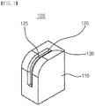
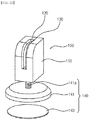
- FIG. 1 is a perspective view illustrating a mounting member in accordance with an example embodiment of the present invention.
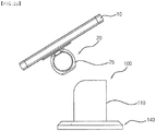
- FIG. 2a is a side view illustrating a status of a mobile device and an accessory to be adapted to the mounting member in FIG. 1 .
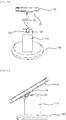
- FIG. 2b is a perspective view illustrating a status of a mobile device and an accessory to be adapted to the mounting member in FIG. 1 .
- FIG. 3a is a side view illustrating a status of a mobile device and an accessory being adapted to the mounting member in FIG. 1 .
- FIG. 3b is a perspective view illustrating a status of a mobile device and an accessory being adapted to the mounting member in FIG. 1 .
- a mounting meber 100 in accordance with an example embodiment includes a body 110, a slot portion 120 and a pressing portion 130.
- the mounting member 100 can be used for mounting a mobile device 10 and a mobile device accessory 20 having a ring 25 and being secured to one side of the mobile device 10 on an object.
- Examples of the mobile device 10 include a mobile phone, a PMP, an MP3 player, an electronic dictionary, a tablet PC, and the like.
- Examples of the object include a cradle, a plate, a dashboard for a vehicle, a selfie stick, a handle bar of a bicycle and a motorcycle, and the like.
- the mobile device accessory 20 is described in detail in the specification of the Korean Patent Application No. 10-2013-0040554 filed on March 12, 2013 , the details of which will be omitted. Further, the mobile device accessory 20 may be variously modified as long as it has a ring 25 and is fixed to one face of the mobile device 10.
- the body 110 may have a rectangular parallelepiped shape. A lower face of the body 110 may be fixed to an upper face of the object.
- a chamfer is formed on an upper edge of the body 110. Accordingly, one side of the mobile device 10 can be supported on the body 110 in a state where the ring 25 is fastened to the mounting member 100.
- the slot portion 120 is formed at a portion of the body 110. That is, the slot portion 120 may be formed at a side wall, an upper portion, or an edge of the body 110. For example, the slot portion 120 is formed at an edge where the chamfer is formed.
- the slot portion 120 is formed with a receiving groove 125 in a vertical direction. Therefore, the receiving groove 125 may receive the ring 25.
- the slot portion 120 may also be formed in a horizontal direction.
- the receiving groove 125 may be formed along an outer periphery of the ring 25. Thus, the ring 25 can be stably received in the receiving groove 125.
- the pressing portion 130 is disposed inside the receiving groove 125, for example, on the side wall.
- the pressing portion 130 is provided so as to be in close contact with the side wall of the receiving groove 125.
- the pressing portion 130 can elastically press the ring 25 located in the receiving groove 125.
- the pressing portion 130 can stably hold the ring 25 located in the receiving groove 125.
- the pressing portion 130 may have a plate shape.
- the pressing portion 130 may be provided on one side wall of the receiving groove 125 or may be disposed on both of the side walls to form a pair.
- the pressing portion 130 may be formed using a polymer resin having elasticity. Thus, when the pressing portion 130 directly contacts the ring 25, the pressing portion 130 may suppress the ring 25 from slipping. Further, the wear of the pressing portion 130 may be suppressed.
- the pressing portion 130 may be made using an engineering plastic having excellent abrasion resistance such as polyacetal, MC nylon, polyurethane, polyisoprene, polybutadiene rubber, polyacrylate rubber, polyether rubber and the like.
- the mounting member 100 includes the pressing portion 130 on the side wall of the receiving groove 125 formed in the slot portion 120 so that the ring 25 received in the receiving groove 125 can be stably clamped from an external impact. Since the pressing portion 130 is made of a polymer resin having elasticity, the slip of the ring 25 can be suppressed and further the wear of the pressing portion 130 can be suppressed.
- FIG. 4 is a front view illustrating a mounting member in accordance with an example embodiment of the present invention.
- a mounting member 100 includes a body 110, a slot portion 120, a pressing portion 130, and a pressurizing part 150.
- a datailed description of the body 110, the slot portion 120, and the pressing portion 130 is substantially the same as that of the body 110, the slot portion 120, and the pressing portion 130 with reference to 130 of FIGS. 1 to 3b , thus to be omitted.
- the pressurizing part 150 is provided to penetrate one side of the body 110.
- the pressurizing part 150 passes through the body 110 in a horizontal direction.
- the pressurizing part 150 can press the pressing portion 130 to press a ring 25 received in a receiving groove 125 more strongly.
- the pressing portion 130 can stably fasten the ring 25 in the receiving groove 125.
- the pressurizing part 150 may have a screw structure, for example.
- the pressurizing part 150 has a handle 151 at an end thereof. The user can press or relax the pressing portion 130 by rotating the pressurzing part 150 using the handle 151.
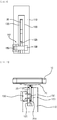
- FIG. 5 is a front view illustrating a mounting member in accordance with an example embodiment of the present invention.
- FIG. 6 is a plan view of the mounting member in FIG. 5 .
- a mounting member 100 includes a body 110, a slot portion 120, a pressing portion 130, and a pressurizing part 152.
- a datailed description of the body 110, the slot portion 120, and the pressing portion 130 is substantially the same as that of the body 110, the slot portion 120, and the pressing portion 130 with reference to 130 of FIGS. 1 to 3b , thus to be omitted.
- the pressurizing part 152 penetrates the body 110 and the pressing portion 130.
- the pressurizing part 152 may pass through the body 110 and the pressing portion 130 along the horizontal direction of the body 110.
- the pressurrizing part 152 presses the pressing portion 130 disposed on one side wall or both side walls of a receiving groove 125 so that the pressing portion 130 presses the ring 25 accommodated in the receiving groove 125 to press the ring 25 more strongly.
- the pressing portion 130 can stably fasten the ring 25 in the receiving groove 125.
- the pressurizing part 152 may include a bolt 153 and a nut 154.
- the bolt 153 penetrates the pressing portion 130 disposed on one side wall or both side walls of the body 110 and the receiving groove 125 along the horizontal direction. At this time, the bolt 153 may have a handle at one end. The bolt 153 can be easily rotated by using the handle.
- the nut 154 is fastened to the bolt 153 and presses the pressing portion 130 together with the bolt 153.
- the bolt 153 and the nut 154 are tightened or loosened by rotating the bolt 153 by using the handle.
- the bolt 153 and the nut 154 When the bolt 153 and the nut 154 are tightened, the bolt 153 and the nut 154 can simultaneously press the pressing portion 130 disposed on one side wall or both side walls. Therefore, the pressing portion 130 can press the ring 25 received in the receiving groove 125 more strongly.
- the pressing portion 130 may be relaxed.
- FIG. 7 is a perspective view illustrating a mounting member in accordance with an example embodiment of the present invention.
- a mounting member 100 includes a body 110, a slot portion 120, a pressing portion 130, and a pressurizing part 156.
- a datailed description of the body 110, the slot portion 120, and the pressing portion 130 is substantially the same as that of the body 110, the slot portion 120, and the pressing portion 130 with reference to 130 of FIGS. 1 to 3b , thus to be omitted.
- the pressurizing part 156 has, for example, a lever structure including a lever. At this time, the pressurizing part 156 can press or relax the pressing portion 130 by rotating the pressurzing part 156 by a user in a manner of rotating the lever.
- FIG. 8 is a front view illustrating a mounting member in accordance with an example embodiment of the present invention.
- FIG. 9 is a plan view of the mounting member in FIG. 8 .
- a mounting member 100 includes a body 110, a slot portion 120, a pressing portion 130, and a pressurizing part 157.
- a datailed description of the body 110, the slot portion 120, and the pressing portion 130 is substantially the same as that of the body 110, the slot portion 120, and the pressing portion 130 with reference to 130 of FIGS. 1 to 3b , thus to be omitted.
- the pressurizing part 157 is provided to pass through the body 110 and the pressing portion 130.
- the pressurizing part 157 pass through the body 110 and the pressing portion 130 along the horizontal direction of the body 110.
- the pressurizing part 157 presses the pressing portion 130 disposed on one side wall or both side walls of a receiving groove 125 so that the pressing portion 130 presses a ring 25 accommodated in the receiving groove 125 more strongly.
- the pressing portion 130 can stably fasten the ring 25 in the receiving groove 125.
- the pressurizing part 157 may include a shaft 158 and a lever 159.
- the shaft 158 passes through the pressing portion 130 disposed on one side wall or both side walls of the body 110 and in the receiving groove 125 along the horizontal direction. At this time, one end of the shaft 158 is fixed to the body 110.
- the shaft 158 has a projection portion at the one end and can be fixed to the body 110 by the projection portion.
- the lever 159 is hinged to other end of the shaft 158, opposite to the one end of the shaft 158.
- the lever 159 rotates with respect to the other end of the shaft 158 so that the projection portion of the shaft 158 and the lever 159 can press the pressing portion 130 or relax the pressing portion 130.
- both the shaft 158 and the lever 159 simultaneously press the pressing portion 130 disposed on the one side wall or the both side walls as well. Therefore, the pressing portion 130 can press the ring 25 received in the receiving groove 125 more strongly.
- FIG. 10 is a pespective view illustrating a mounting member in accordance with an example embodiment of the present invention.
- a mounting member 100 includes a body 110, a slot portion 120, a pressing portion 130, and a release preventing part 160.
- a datailed description of the body 110, the slot portion 120, and the pressing portion 130 is substantially the same as that of the body 110, the slot portion 120, and the pressing portion 130 with reference to 130 of FIGS. 1 to 3b , thus to be omitted.
- the release preventing part 160 is disposed to pass through the side wall of the body 110 in a horizontal direction.
- the release preventing part 160 can secure a ring 25 received in a receiving groove 125 to prevent the ring 25 from being released from the receiving groove 125.
- the release preventing part 160 passes through the pressing portion 130 and includes a protrusion portion 161.
- the protrusion portion 161 is provided so as to be slidable in the horizontal direction so as to make in contact with an inside of the ring 25 or to be spaced from the inside of the ring 25. Accordingly, when the user presses the release preventing part 160, the protrusion portion 161 included in the release preventing part 160 moves to the receiving groove 125 to make contact with the inside of the ring 25. Thus, the release preventing part 160 can prevent the ring 25 from being released from the receiving groove 125.
- FIG. 11 is a pespective view illustrating a mounting member in accordance with an example embodiment of the present invention.
- a mounting member 100 includes a body 110, a slot portion 120, a pressing portion 130, and a release preventing part 160.
- a datailed description of the body 110, the slot portion 120, and the pressing portion 130 is substantially the same as that of the body 110, the slot portion 120, and the pressing portion 130 with reference to 130 of FIGS. 1 to 3b , thus to be omitted.
- the release preventing part 160 includes a push portion 165, a hook 166 and an elastic member 168.
- the push portion 165 is provided inside the body 110 so as to surround the slot portion 120.
- the push portion 165 may have a U-shape.
- the push portion 165 may include a button formed at one end thereof, and movable in the horizontal direction by a force externally applied. Accordingly, when the user presses the button, the push portion 165 can move in the horizontal direction as a whole.
- the hook 166 is formed at the other end of the push portion 165.
- the hook 166 is provided to fix a ring 25 in a receiving groove 125 when the ring 25 is received. in the slot portion 120.
- the hook 166 includes an inclined face inclined toward the inside of the push portion 165.
- the elastic member 168 is adjacent to the hook 166 and is resiliently connected to the push portion 165.
- the elastic member 168 fixes the hook 166 to the receiving groove 125.
- the push portion 165 moves in the horizontal direction as a whole and the elastic member 168 is compressed.
- the ring 25 is mounted on the receiving groove 125 along the inclined face formed on the hook 166.
- the pushing portion 165 returns to an initial position by a restoring force of the elastic member 168. At this time, as the ring 25 is fastened to the hook 166, the ring 25 can be fixed to the receiving groove 125.
- the push portion 165 when the push portion 165 is pressed by an external force, the push portion 165 is moved in the horizontal direction as a whole, so that the hook 166 can release the ring 25.
- FIG. 12 is a pespective view illustrating a mounting member in accordance with an example embodiment of the present invention.
- a mounting member 100 includes a body 110, a slot portion 120, a pressing portion 130, and an attaching part 140.
- a datailed description of the body 110, the slot portion 120, and the pressing portion 130 is substantially the same as that of the body 110, the slot portion 120, and the pressing portion 130 with reference to 130 of FIGS. 1 to 3b , thus to be omitted.
- the mounting member 100 may further include the pressurizing part 150, the pressurizing part 152, the pressurizing part 156, the pressurizing part 157 or the release preventing part 160 as illustrated with reference to FIGS. 4 to 11 .
- the attaching part 140 includes a base housing 141 and an adhesive member 143.
- the base housing 141 is connected to a lower surface of the body 110.
- the upper face of the base housing 141 is provided with a joint portion 141a having a thread.
- a screw groove (not shown) is formed on the lower surface of the body 110.
- the joint portion 141a is screwed into the screw groove so that the attaching part 140 can be mounted on the body 110. That is, the attaching portion 140 and the body 110 have a screw connection structure.
- the joint portion may be formed on the lower surface of the body 110, and a screw groove may be formed on the upper surface of the base housing 141.
- the adhesive member 143 is interposed between the lower face of the base housing 141 and an object to provide an adhesive force.
- the adhesive member 143 includes an adhesive tape or a magnetic substance having magnetism.
- FIGS. 13 and 14 are front views illustrating a combining structure between the body and the attaching part in FIG. 12 ;
- a protrusion 141b extending in one direction may be formed on the upper surface of the base housing 141.
- the protrusion 141b has a substantially 'T' shape.
- a coupling groove 111 having a shape corresponding to the shape of the projection 141b is formed on the lower surface of the body 110.
- the coupling groove 111 extends to one side of the body 110.
- the protrusion 141b slides through one side of the body 110 and is inserted into the coupling groove 111.
- the attaching part 140 can be mounted on the body 110. That is, the attaching part 140 and the body 110 have a sliding coupling structure.
- the protrusion 141b may be formed on the lower surface of the body 110 and the coupling groove 111 may be formed on the upper surface of the base housing 141.
- a hook 112 may be provided on one side of the body 110 where the coupling groove 111 is formed.
- the hook 112 opens the coupling groove 111.
- the hook 112 is moved to block off the coupling groove 111. Therefore, it is possible to prevent the protrusion 141 b from being detached from the coupling groove 111. That is, the attaching part 140 and the body 110 have a sliding coupling structure or a hook fixing structure.
- the protrusion 141 b may be formed on the lower surface of the body 110 and the coupling groove 111 and the hook 112 may be formed on the upper surface of the base housing 141.
- the body 110 and the attachment portion 140 may be coupled to each other with various coupling structures.
- FIG. 15 is a pespective view illustrating a mounting member in accordance with an example embodiment of the present invention.
- a mounting member 100 includes a body 110, a slot portion 120, a pressing portion 130, and an attaching part 140.
- a datailed description of the body 110, the slot portion 120, and the pressing portion 130 is substantially the same as that of the body 110, the slot portion 120, and the pressing portion 130 with reference to 130 of FIGS. 1 to 3b , thus to be omitted.
- the mounting member 100 may further include the pressurizing part 150, the pressurizing part 152, the pressurizing part 156, the pressurizing part 157 or the release preventing part 160 as illustrated with reference to FIGS. 4 to 11 .
- the attaching part 140 includes a base housing 141, a base bottom plate 142 and a suction plate 144.
- the base housing 141 is coupled to a lower surface of the body 110.
- the base housing 141 and the bottom surface of the body 110 are coupled to each other with a screw-coupling structure, a sliding-coupling structure, or a sliding-coupling structure and a hook-coupling structure.
- the base bottom plate 142 is disposed at a lower portion of the base housing 141.
- the base bottom plate 142 may have a dome shape so that the suction plate 144 can be fastened.
- the suction plate 144 is fastened to the base housing 141 through the lower base plate 142.
- the suction plate 144 is adsorbed on an object.
- the suction plate 144 may be adsorbed to the object using a vacuum force.
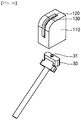
- FIG. 16 is a perspective view illustrating a status of the mounting member in FIG. 1 to be mounted on an object.
- a mounting member 100 includes a body 110, a slot portion 120 and a pressing portion 130 in order to mount a mobile device accessory on an object.
- a datailed description of the body 110, the slot portion 120, and the pressing portion 130 is substantially the same as that of the body 110, the slot portion 120, and the pressing portion 130 with reference to 130 of FIGS. 1 to 3b , thus to be omitted.
- the mounting member 100 may further include the pressurizing part 150, the pressurizing part 152, the pressurizing part 156, the pressurizing part 157 or the release preventing part 160 as illustrated with reference to FIGS. 4 to 11 .
- the object 30 is a selfie stick capable of taking an image using a mobile device in a self-camera mode.
- the selfie stick is provided with a fastening portion 31 formed with threads.
- a screw groove (not shown) is formed on the lower surface of the body 110.
- the mounting member 100 can be mounted on the object by screwing the fastening portion 31 into the screw groove. That is, the mounting member 100 and the object have a threaded connection structure.
- the mounting member 100 and the object may have a sliding coupling structure, or may have the sliding coupling structure and the hook coupling structure.
- FIG. 17a is a perspective view illustrating illustrating a status of the mounting member in FIG. 1 being mounted on an object.
- FIG. 17b is a side view of the mounting member in FIG. 17a .
- a mounting member 100 includes a body 110, a slot portion 120, a pressing portion 130 and an attacing part 140 in order to mount a mobile device accessory on an object.
- a datailed description of the body 110, the slot portion 120, and the pressing portion 130 is substantially the same as that of the body 110, the slot portion 120, and the pressing portion 130 with reference to 130 of FIGS. 1 to 3b , thus to be omitted.
- the mounting member 100 may further include the pressurizing part 150, the pressurizing part 152, the pressurizing part 156, the pressurizing part 157 or the release preventing part 160 as illustrated with reference to FIGS. 4 to 11 .
- the attaching part 140 is coupled to a lower surface of the body 110.
- the attaching part 140 and on a lower surface of the body 110 are connected to each other by the screw coupling structure, the sliding coupling structure or the sliding coupling structure and the hook coupling structure.
- the attaching part 140 includes a clamp 146 formed with a through-hole 145 in a horizontal direction.
- the object 30 may be fixed to the clamp 146 along the through-hole 145.
- the mounting member according to the present invention can stably mount both the mobile device and the accessory having the ring and being attached to one side of the mobile device to the object.
Landscapes
- Engineering & Computer Science (AREA)
- General Engineering & Computer Science (AREA)
- Mechanical Engineering (AREA)
- Signal Processing (AREA)
- Telephone Set Structure (AREA)
- Casings For Electric Apparatus (AREA)
- Connection Of Plates (AREA)
- Clamps And Clips (AREA)
- Hooks, Suction Cups, And Attachment By Adhesive Means (AREA)
Abstract
Description
- This application claims priority under 35 USC § 119 to Korean Patent Application No.
10-2015-0001282 filed on January 6, 2015 20-2015-0008298 filed on December 16, 2015 - Example embodiments of the present invention relate to a mounting member. More particularly, example embodiments of the present invention relate to a mounting member for mounting a mobile device and a mobile device accessory including a ring to be fixed to a face of the mobile device to an object.
- Recently, a mobile device such as a portable media player (PMP) has come into wide use. Users have utilized various accessories in order to carry the mobile device easily. For example, a strap-type accessory which can bind one side of the mobile device helps the users to carry the mobile device conveniently.
- While the mobile device generally operates while grasping the mobile device with hands, the mobile device may work occasionally with being positioned on a bottom face of a desk when the users watch a video for a long time.
- When the mobile device is mounted on a particular position such as a vehicle, a bicycle, etc., a fixing member may be required for fixing the mobile device by using a clamping structure or a spring elastic structure.
- The disadvantage of the clamping structure is that a size of the clamping structure must increase as a size of the mobile device increases. In recent years, as the sizes of smart phones and tablets have become larger and larger, there has been a problem that the size of a fixing member included in the clamping structure has to increase proportionally. Furthermore, the fixing member may be very obstructive to a view of a driver while driving the vehicle, and even when not in use, the clamping structure may occupy a wide area of a dashboard of the vehicle.
- Further, the fixing member included in the clamping structure can grip the mobile device using a spring. Thus, the clamping structure is very vulnerable to external impacts such that there is a high possibility that a breakage of the spring occurs due to a shock while driving the vehicle or the bicycle on an uneven road. As a result, the spring may leave out of a clamper of holding the mobile device due to elastic characteristics.
- Example embodiments of the present invention provide a mounting member for mounting a mobile device on an object stably.
- According to one aspect of the present invention, there is provided a mounting member for mounting a mobile device and a mobile device accessory of being fixed to one face of the mobile device and having a ring on an object, the mounting member includes a body, a slot portion being formed in a part of the body and having a receiving groove for receiving the ring and a pressing portion disposed inside the receiving groove and configured to elastically press the ring to be located in the receiving groove.
- In an example embodiment, the slot portion and the pressing portion may be formed parallel to each other.
- In an example embodiment, the pressing portion may be formed using polymer resin.
- In an example embodiment, the mounting member may further include a pressurizing part disposed to penetrate through a side wall of the body in a horizontal direction, the pressurizing part being configured to press the pressing portion to fix the ring.
- In an example embodiment, the pressurizing part may have a screw structure or a lever structure.
- In an example embodiment, the pressing portion may be disposed on one side wall or both side walls of the receiving groove, and the mounting member may further include a pressurizing part disposed to penetrate through the body to the pressing portion along a horizontal direction of the body to press the pressing portion disposed on one side wall or both side walls of the receiving groove such that the pressing portion fixes the ring.
- In an example embodiment, the pressurizing part may include a bolt passing through the body and the pressing portion along the horizontal direction and a nut fastened to the bolt to press the pressing portion together with the bolt.
- In an example embodiment, the pressurizing part may include a shaft passing through the body and the pressing portion along the horizontal direction and having one end fixed to the body and a lever hinged to the other end of the shaft opposite to the one end, and the lever capable of rotating with respect to the other end of the shaft to press or release the pressing portion.
- In an example embodiment, the mounting member may further include a release preventing part being disposed to penetrate through a sidewall of the body in a horizontal direction to fix the ring received in the receiving groove to prevent the ring from being released from the receiving groove.
- In an example embodiment, the release preventing part may include a protrusion penetrating the pressing portion and being slidable in the horizontal direction to make contact with an inside of the ring or to be spaced from the inside of the ring
- In an example embodiment, the release preventing part may include a push portion being provided inside the body to surround the slot portion, and having a button movable in the horizontal direction by a force externally pressed at one end, a hook formed at the other end of the push portion and adapted to fix the ring in the receiving groove as the ring is received in the receiving groove, and an elastic member being adjacent to the hook and being resiliently connected to the push portion to fix the hook in the receiving groove.
- In an example embodiment, the body may include a fastening portion formed on a lower surface of the body to be fastend to the object by a screw or a sliding method.
- In an example embodiment, the mounting member may further include an attaching part to attach a lower surface of the body to the object.
- In an example embodiment, the attaching part may include a base housing coupled to a lower surface of the body and an adhesive member interposed between a lower surface of the base housing and the object to providing an adhesive force therebewteen.
- In an example embodiment, the attaching part may include a base housing coupled to a lower surface of the body, a base bottom plate disposed at a lower face of the base housing, and a suction plate being configured to be fastened to the base housing through the base bottom plate and to adsorb the object.
- In an example embodiment, the attaching part may include a clamp being coupled to a lower surface of the body and having a through-hole formed in a horizontal direction.
- According to one aspect of the present invention, there is provided a mounting member for mounting a mobile device and a mobile device accessory of being fixed to one face of the mobile device and having a ring on an object, the mounting member includes a body, a slot portion being formed in a part of the body and having a receiving groove for receiving the ring, and a release preventing part being disposed to penetrate through a sidewall of the body in a horizontal direction to fix the ring received in the receiving groove to prevent the ring from being released from the receiving groove.
- In an example embodiment, wherein the release preventing part may include a protrusion being slidable in the horizontal direction to make contact with an inside of the ring or to be spaced from the inside of the ring
- In an example embodiment, wherein the release preventing part may include a push portion being provided inside the body to surround the slot portion, and having a button movable in the horizontal direction by a force externally pressed at one end, a hook formed at the other end of the push portion and adapted to fix the ring in the receiving groove as the ring is received in the receiving groove, and an elastic member being adjacent to the hook and being resiliently connected to the push portion to fix the hook in the receiving groove.
- According to example embodiments, the mounting member includes a pressing portion on the side wall of the receiving groove formed in the slot portion, so that the ring received in the receiving groove can be stably mounted, even though the external impact is applied. Since the pressing portion is made of polymer resin having elasticity, the ring may be suppressed from slipping and further the abrasion of the pressing portion can be suppressed.
- Further, since the pressurizing part is provided to press the pressing portion, the pressing portion can press the ring received in the receiving groove more strongly. As a result, the pressing portion can stably fasten the ring in the receiving groove.
- In addition, the mounting member includes the release preventing part, so that the ring received in the receiving groove can be fixed to prevent the ring from being released from the receiving groove.
- The above and other features and advantages of the present invention will become more apparent by describing in detailed example embodiments thereof with reference to the accompanying drawings, in which:
-
FIG. 1 is a perspective view illustrating a mounting member in accordance with an example embodiment of the present invention; -
FIG. 2a is a side view illustrating a status of a mobile device and an accessory to be adapted to the mounting member inFIG. 1 ; -
FIG. 2b is a perspective view illustrating a status of a mobile device and an accessory to be adapted to the mounting member inFIG. 1 ; -
FIG. 3a is a side view illustrating a status of a mobile device and an accessory being adapted to the mounting member inFIG. 1 ; -
FIG. 3b is a perspective view illustrating a status of a mobile device and an accessory being adapted to the mounting member inFIG. 1 ; -
FIG. 4 is a front view illustrating a mounting member in accordance with an example embodiment of the present invention; -
FIG. 5 is a front view illustrating a mounting member in accordance with an example embodiment of the present invention; -
FIG. 6 is a plan view of the mounting member inFIG. 5 ; -
FIG. 7 is a perspective view illustrating a mounting member in accordance with an example embodiment of the present invention; -
FIG. 8 is a front view illustrating a mounting member in accordance with an example embodiment of the present invention; -
FIG. 9 is a plan view of the mounting member inFIG. 8 ; -
FIG. 10 is a pespective view illustrating a mounting member in accordance with an example embodiment of the present invention; -
FIG. 11 is a pespective view illustrating a mounting member in accordance with an example embodiment of the present invention; -
FIG. 12 is a pespective view illustrating a mounting member in accordance with an example embodiment of the present invention; -
FIGS. 13 and 14 are front views illustrating a combining structure between the body and the attaching part inFIG. 12 ; -
FIG. 15 is a pespective view illustrating a mounting member in accordance with an example embodiment of the present invention; -
FIG. 16 is a perspective view illustrating a status of the mounting member inFIG. 1 to be mounted on an object; -
FIG. 17a is a perspective view illustrating illustrating a status of the mounting member inFIG. 1 being mounted on an object; and -
FIG. 17b is a side view of the mounting member inFIG. 17a . - Hereinafter, mounting members are described more fully hereinafter with reference to the accompanying drawings, in which embodiments of the invention are shown. This invention may, however, be embodied in many different forms and should not be construed as limited to the embodiments set forth herein. Rather, these embodiments are provided so that this disclosure will be thorough and complete, and will fully convey the scope of the invention to those skilled in the art. In the drawings, the sizes and relative sizes of layers and regions may be exaggerated for clarity.
- It will be understood that, although the terms first, second, etc. may be used herein to describe various elements, components, regions, layers and/or sections, these elements, components, regions, layers and/or sections should not be limited by these terms. These terms are only used to distinguish one element, component, region, layer or section from another region, layer or section. Thus, a first element discussed below could be termed a second element without departing from the teachings of the present invention.
- The terminology used herein is for the purpose of describing particular embodiments only and is not intended to be limiting of the invention. As used herein, the singular forms "a", "an" and "the" are intended to include the plural forms as well, unless the context clearly indicates otherwise. It will be further understood that the terms "comprises" and/or "comprising," when used in this specification, specify the presence of stated features, integers, steps, operations, elements, and/or components, but do not preclude the presence or addition of one or more other features, integers, steps, operations, elements, components, and/or groups thereof.
- Unless otherwise defined, all terms (including technical and scientific terms) used herein have the same meaning as commonly understood by one of ordinary skill in the art to which this invention belongs. It will be further understood that terms, such as those defined in commonly used dictionaries, should be interpreted as having a meaning that is consistent with their meaning in the context of the relevant art and will not be interpreted in an idealized or overly formal sense unless expressly so defined herein.
-
FIG. 1 is a perspective view illustrating a mounting member in accordance with an example embodiment of the present invention.FIG. 2a is a side view illustrating a status of a mobile device and an accessory to be adapted to the mounting member inFIG. 1 .FIG. 2b is a perspective view illustrating a status of a mobile device and an accessory to be adapted to the mounting member inFIG. 1 .FIG. 3a is a side view illustrating a status of a mobile device and an accessory being adapted to the mounting member inFIG. 1 .FIG. 3b is a perspective view illustrating a status of a mobile device and an accessory being adapted to the mounting member inFIG. 1 . - Referring to
FIGS. 1 to 3b , a mountingmeber 100 in accordance with an example embodiment includes abody 110, aslot portion 120 and apressing portion 130. The mountingmember 100 can be used for mounting amobile device 10 and amobile device accessory 20 having aring 25 and being secured to one side of themobile device 10 on an object. Examples of themobile device 10 include a mobile phone, a PMP, an MP3 player, an electronic dictionary, a tablet PC, and the like. - Examples of the object include a cradle, a plate, a dashboard for a vehicle, a selfie stick, a handle bar of a bicycle and a motorcycle, and the like.
- An example of the
mobile device accessory 20 is described in detail in the specification of the Korean Patent Application No.10-2013-0040554 filed on March 12, 2013 mobile device accessory 20 may be variously modified as long as it has aring 25 and is fixed to one face of themobile device 10. - The
body 110 may have a rectangular parallelepiped shape. A lower face of thebody 110 may be fixed to an upper face of the object. - A chamfer is formed on an upper edge of the
body 110. Accordingly, one side of themobile device 10 can be supported on thebody 110 in a state where thering 25 is fastened to the mountingmember 100. - The
slot portion 120 is formed at a portion of thebody 110. That is, theslot portion 120 may be formed at a side wall, an upper portion, or an edge of thebody 110. For example, theslot portion 120 is formed at an edge where the chamfer is formed. - The
slot portion 120 is formed with a receivinggroove 125 in a vertical direction. Therefore, the receivinggroove 125 may receive thering 25. Theslot portion 120 may also be formed in a horizontal direction. - The receiving
groove 125 may be formed along an outer periphery of thering 25. Thus, thering 25 can be stably received in the receivinggroove 125. - The
pressing portion 130 is disposed inside the receivinggroove 125, for example, on the side wall. Thepressing portion 130 is provided so as to be in close contact with the side wall of the receivinggroove 125. Thepressing portion 130 can elastically press thering 25 located in the receivinggroove 125. Thus, thepressing portion 130 can stably hold thering 25 located in the receivinggroove 125. Thepressing portion 130 may have a plate shape. - The
pressing portion 130 may be provided on one side wall of the receivinggroove 125 or may be disposed on both of the side walls to form a pair. Thepressing portion 130 may be formed using a polymer resin having elasticity. Thus, when thepressing portion 130 directly contacts thering 25, thepressing portion 130 may suppress thering 25 from slipping. Further, the wear of thepressing portion 130 may be suppressed. - The
pressing portion 130 may be made using an engineering plastic having excellent abrasion resistance such as polyacetal, MC nylon, polyurethane, polyisoprene, polybutadiene rubber, polyacrylate rubber, polyether rubber and the like. - The mounting
member 100 according to an embodiment of the present invention includes thepressing portion 130 on the side wall of the receivinggroove 125 formed in theslot portion 120 so that thering 25 received in the receivinggroove 125 can be stably clamped from an external impact. Since thepressing portion 130 is made of a polymer resin having elasticity, the slip of thering 25 can be suppressed and further the wear of thepressing portion 130 can be suppressed. -
FIG. 4 is a front view illustrating a mounting member in accordance with an example embodiment of the present invention. - Referring to
FIG. 4 , a mountingmember 100 according to an embodiment of the present invention includes abody 110, aslot portion 120, apressing portion 130, and a pressurizingpart 150. - A datailed description of the
body 110, theslot portion 120, and thepressing portion 130 is substantially the same as that of thebody 110, theslot portion 120, and thepressing portion 130 with reference to 130 ofFIGS. 1 to 3b , thus to be omitted. - The pressurizing
part 150 is provided to penetrate one side of thebody 110. For example, the pressurizingpart 150 passes through thebody 110 in a horizontal direction. The pressurizingpart 150 can press thepressing portion 130 to press aring 25 received in a receivinggroove 125 more strongly. Thus, thepressing portion 130 can stably fasten thering 25 in the receivinggroove 125. - The pressurizing
part 150 may have a screw structure, for example. At this case, the pressurizingpart 150 has ahandle 151 at an end thereof. The user can press or relax thepressing portion 130 by rotating thepressurzing part 150 using thehandle 151. -
FIG. 5 is a front view illustrating a mounting member in accordance with an example embodiment of the present invention.FIG. 6 is a plan view of the mounting member inFIG. 5 . - Referring to
FIGS. 5 and6 , a mountingmember 100 according to an embodiment of the present invention includes abody 110, aslot portion 120, apressing portion 130, and a pressurizingpart 152. - A datailed description of the
body 110, theslot portion 120, and thepressing portion 130 is substantially the same as that of thebody 110, theslot portion 120, and thepressing portion 130 with reference to 130 ofFIGS. 1 to 3b , thus to be omitted. - The pressurizing
part 152 penetrates thebody 110 and thepressing portion 130. For example, the pressurizingpart 152 may pass through thebody 110 and thepressing portion 130 along the horizontal direction of thebody 110. Thepressurrizing part 152 presses thepressing portion 130 disposed on one side wall or both side walls of a receivinggroove 125 so that thepressing portion 130 presses thering 25 accommodated in the receivinggroove 125 to press thering 25 more strongly. Thus, thepressing portion 130 can stably fasten thering 25 in the receivinggroove 125. - The pressurizing
part 152 may include abolt 153 and anut 154. - The
bolt 153 penetrates thepressing portion 130 disposed on one side wall or both side walls of thebody 110 and the receivinggroove 125 along the horizontal direction. At this time, thebolt 153 may have a handle at one end. Thebolt 153 can be easily rotated by using the handle. - The
nut 154 is fastened to thebolt 153 and presses thepressing portion 130 together with thebolt 153. Thebolt 153 and thenut 154 are tightened or loosened by rotating thebolt 153 by using the handle. - When the
bolt 153 and thenut 154 are tightened, thebolt 153 and thenut 154 can simultaneously press thepressing portion 130 disposed on one side wall or both side walls. Therefore, thepressing portion 130 can press thering 25 received in the receivinggroove 125 more strongly. - When the
bolt 153 and thenut 154 are loosened, thepressing portion 130 may be relaxed. -
FIG. 7 is a perspective view illustrating a mounting member in accordance with an example embodiment of the present invention. - Referring to
FIG. 7 , a mountingmember 100 according to an embodiment of the present invention includes abody 110, aslot portion 120, apressing portion 130, and a pressurizingpart 156. - A datailed description of the
body 110, theslot portion 120, and thepressing portion 130 is substantially the same as that of thebody 110, theslot portion 120, and thepressing portion 130 with reference to 130 ofFIGS. 1 to 3b , thus to be omitted. - The pressurizing
part 156 has, for example, a lever structure including a lever. At this time, the pressurizingpart 156 can press or relax thepressing portion 130 by rotating thepressurzing part 156 by a user in a manner of rotating the lever. -
FIG. 8 is a front view illustrating a mounting member in accordance with an example embodiment of the present invention.FIG. 9 is a plan view of the mounting member inFIG. 8 . - Referring to
FIGS. 8 and9 , a mountingmember 100 according to an embodiment of the present invention includes abody 110, aslot portion 120, apressing portion 130, and a pressurizingpart 157. - A datailed description of the
body 110, theslot portion 120, and thepressing portion 130 is substantially the same as that of thebody 110, theslot portion 120, and thepressing portion 130 with reference to 130 ofFIGS. 1 to 3b , thus to be omitted. - The pressurizing
part 157 is provided to pass through thebody 110 and thepressing portion 130. For example, the pressurizingpart 157 pass through thebody 110 and thepressing portion 130 along the horizontal direction of thebody 110. The pressurizingpart 157 presses thepressing portion 130 disposed on one side wall or both side walls of a receivinggroove 125 so that thepressing portion 130 presses aring 25 accommodated in the receivinggroove 125 more strongly. Thus, thepressing portion 130 can stably fasten thering 25 in the receivinggroove 125. - The pressurizing
part 157 may include ashaft 158 and alever 159. - The
shaft 158 passes through thepressing portion 130 disposed on one side wall or both side walls of thebody 110 and in the receivinggroove 125 along the horizontal direction. At this time, one end of theshaft 158 is fixed to thebody 110. For example, theshaft 158 has a projection portion at the one end and can be fixed to thebody 110 by the projection portion. - The
lever 159 is hinged to other end of theshaft 158, opposite to the one end of theshaft 158. Thelever 159 rotates with respect to the other end of theshaft 158 so that the projection portion of theshaft 158 and thelever 159 can press thepressing portion 130 or relax thepressing portion 130. - The projection portion of the
shaft 158 and thelever 159 pressed against thepressing portion 130. In detail, both theshaft 158 and thelever 159 simultaneously press thepressing portion 130 disposed on the one side wall or the both side walls as well. Therefore, thepressing portion 130 can press thering 25 received in the receivinggroove 125 more strongly. -
FIG. 10 is a pespective view illustrating a mounting member in accordance with an example embodiment of the present invention. - Referring to
FIG. 10 , a mountingmember 100 according to an embodiment of the present invention includes abody 110, aslot portion 120, apressing portion 130, and arelease preventing part 160. - A datailed description of the
body 110, theslot portion 120, and thepressing portion 130 is substantially the same as that of thebody 110, theslot portion 120, and thepressing portion 130 with reference to 130 ofFIGS. 1 to 3b , thus to be omitted. - The
release preventing part 160 is disposed to pass through the side wall of thebody 110 in a horizontal direction. Therelease preventing part 160 can secure aring 25 received in a receivinggroove 125 to prevent thering 25 from being released from the receivinggroove 125. - The
release preventing part 160 passes through thepressing portion 130 and includes aprotrusion portion 161. Theprotrusion portion 161 is provided so as to be slidable in the horizontal direction so as to make in contact with an inside of thering 25 or to be spaced from the inside of thering 25. Accordingly, when the user presses therelease preventing part 160, theprotrusion portion 161 included in therelease preventing part 160 moves to the receivinggroove 125 to make contact with the inside of thering 25. Thus, therelease preventing part 160 can prevent thering 25 from being released from the receivinggroove 125. -
FIG. 11 is a pespective view illustrating a mounting member in accordance with an example embodiment of the present invention. - Referring to
FIG. 11 , a mountingmember 100 according to an embodiment of the present invention includes abody 110, aslot portion 120, apressing portion 130, and arelease preventing part 160. - A datailed description of the
body 110, theslot portion 120, and thepressing portion 130 is substantially the same as that of thebody 110, theslot portion 120, and thepressing portion 130 with reference to 130 ofFIGS. 1 to 3b , thus to be omitted. - The
release preventing part 160 includes apush portion 165, ahook 166 and anelastic member 168. - The
push portion 165 is provided inside thebody 110 so as to surround theslot portion 120. Thus, thepush portion 165 may have a U-shape. Thepush portion 165 may include a button formed at one end thereof, and movable in the horizontal direction by a force externally applied. Accordingly, when the user presses the button, thepush portion 165 can move in the horizontal direction as a whole. - The
hook 166 is formed at the other end of thepush portion 165. Thehook 166 is provided to fix aring 25 in a receivinggroove 125 when thering 25 is received. in theslot portion 120. Thehook 166 includes an inclined face inclined toward the inside of thepush portion 165. - The
elastic member 168 is adjacent to thehook 166 and is resiliently connected to thepush portion 165. Theelastic member 168 fixes thehook 166 to the receivinggroove 125. - When the
ring 25 is drawn into the receivinggroove 125 from the outside, thepush portion 165 moves in the horizontal direction as a whole and theelastic member 168 is compressed. Thering 25 is mounted on the receivinggroove 125 along the inclined face formed on thehook 166. - Then, when the
ring 25 passes the inclined face completely, the pushingportion 165 returns to an initial position by a restoring force of theelastic member 168. At this time, as thering 25 is fastened to thehook 166, thering 25 can be fixed to the receivinggroove 125. - On the other hand, when the
push portion 165 is pressed by an external force, thepush portion 165 is moved in the horizontal direction as a whole, so that thehook 166 can release thering 25. -
FIG. 12 is a pespective view illustrating a mounting member in accordance with an example embodiment of the present invention. - Referring to
FIG. 12 , a mountingmember 100 according to an embodiment of the present invention includes abody 110, aslot portion 120, apressing portion 130, and an attachingpart 140. - A datailed description of the
body 110, theslot portion 120, and thepressing portion 130 is substantially the same as that of thebody 110, theslot portion 120, and thepressing portion 130 with reference to 130 ofFIGS. 1 to 3b , thus to be omitted. - Further, the mounting
member 100 may further include the pressurizingpart 150, the pressurizingpart 152, the pressurizingpart 156, the pressurizingpart 157 or therelease preventing part 160 as illustrated with reference toFIGS. 4 to 11 . - The attaching
part 140 includes abase housing 141 and anadhesive member 143. - The
base housing 141 is connected to a lower surface of thebody 110. The upper face of thebase housing 141 is provided with ajoint portion 141a having a thread. A screw groove (not shown) is formed on the lower surface of thebody 110. Thejoint portion 141a is screwed into the screw groove so that the attachingpart 140 can be mounted on thebody 110. That is, the attachingportion 140 and thebody 110 have a screw connection structure. - In another example embodiment, the joint portion may be formed on the lower surface of the
body 110, and a screw groove may be formed on the upper surface of thebase housing 141. - The
adhesive member 143 is interposed between the lower face of thebase housing 141 and an object to provide an adhesive force. For example, theadhesive member 143 includes an adhesive tape or a magnetic substance having magnetism. -
FIGS. 13 and 14 are front views illustrating a combining structure between the body and the attaching part inFIG. 12 ; - Referring to
FIG. 13 , aprotrusion 141b extending in one direction may be formed on the upper surface of thebase housing 141. For example, theprotrusion 141b has a substantially 'T' shape. Acoupling groove 111 having a shape corresponding to the shape of theprojection 141b is formed on the lower surface of thebody 110. Thecoupling groove 111 extends to one side of thebody 110. Theprotrusion 141b slides through one side of thebody 110 and is inserted into thecoupling groove 111. Accordingly, the attachingpart 140 can be mounted on thebody 110. That is, the attachingpart 140 and thebody 110 have a sliding coupling structure. - In the meantime, the
protrusion 141b may be formed on the lower surface of thebody 110 and thecoupling groove 111 may be formed on the upper surface of thebase housing 141. - Referring to
FIG. 14 , ahook 112 may be provided on one side of thebody 110 where thecoupling groove 111 is formed. When theprotrusion 141b is inserted into thecoupling groove 111, thehook 112 opens thecoupling groove 111. When theprotrusion 141b is inserted into thecoupling groove 111, thehook 112 is moved to block off thecoupling groove 111. Therefore, it is possible to prevent theprotrusion 141 b from being detached from thecoupling groove 111. That is, the attachingpart 140 and thebody 110 have a sliding coupling structure or a hook fixing structure. - The
protrusion 141 b may be formed on the lower surface of thebody 110 and thecoupling groove 111 and thehook 112 may be formed on the upper surface of thebase housing 141. - In addition, the
body 110 and theattachment portion 140 may be coupled to each other with various coupling structures. -
FIG. 15 is a pespective view illustrating a mounting member in accordance with an example embodiment of the present invention. - Referring to
FIG. 15 , a mountingmember 100 according to an embodiment of the present invention includes abody 110, aslot portion 120, apressing portion 130, and an attachingpart 140. - A datailed description of the
body 110, theslot portion 120, and thepressing portion 130 is substantially the same as that of thebody 110, theslot portion 120, and thepressing portion 130 with reference to 130 ofFIGS. 1 to 3b , thus to be omitted. - Further, the mounting
member 100 may further include the pressurizingpart 150, the pressurizingpart 152, the pressurizingpart 156, the pressurizingpart 157 or therelease preventing part 160 as illustrated with reference toFIGS. 4 to 11 . - The attaching
part 140 includes abase housing 141, a basebottom plate 142 and asuction plate 144. - The
base housing 141 is coupled to a lower surface of thebody 110. For example, thebase housing 141 and the bottom surface of thebody 110 are coupled to each other with a screw-coupling structure, a sliding-coupling structure, or a sliding-coupling structure and a hook-coupling structure. - The base
bottom plate 142 is disposed at a lower portion of thebase housing 141. The basebottom plate 142 may have a dome shape so that thesuction plate 144 can be fastened. - The
suction plate 144 is fastened to thebase housing 141 through thelower base plate 142. Thesuction plate 144 is adsorbed on an object. Thesuction plate 144 may be adsorbed to the object using a vacuum force. -
FIG. 16 is a perspective view illustrating a status of the mounting member inFIG. 1 to be mounted on an object. - Referring to
FIG. 16 , a mountingmember 100 according to an embodiment of the present invention includes abody 110, aslot portion 120 and apressing portion 130 in order to mount a mobile device accessory on an object. - A datailed description of the
body 110, theslot portion 120, and thepressing portion 130 is substantially the same as that of thebody 110, theslot portion 120, and thepressing portion 130 with reference to 130 ofFIGS. 1 to 3b , thus to be omitted. - Further, the mounting
member 100 may further include the pressurizingpart 150, the pressurizingpart 152, the pressurizingpart 156, the pressurizingpart 157 or therelease preventing part 160 as illustrated with reference toFIGS. 4 to 11 . - For example, the
object 30 is a selfie stick capable of taking an image using a mobile device in a self-camera mode. the selfie stick is provided with afastening portion 31 formed with threads. - A screw groove (not shown) is formed on the lower surface of the
body 110. The mountingmember 100 can be mounted on the object by screwing thefastening portion 31 into the screw groove. That is, the mountingmember 100 and the object have a threaded connection structure. - Meanwhile, the mounting
member 100 and the object may have a sliding coupling structure, or may have the sliding coupling structure and the hook coupling structure. -
FIG. 17a is a perspective view illustrating illustrating a status of the mounting member inFIG. 1 being mounted on an object.FIG. 17b is a side view of the mounting member inFIG. 17a . - Referring to
FIG. 17a and 17b , a mountingmember 100 according to an embodiment of the present invention includes abody 110, aslot portion 120, apressing portion 130 and anattacing part 140 in order to mount a mobile device accessory on an object. - A datailed description of the
body 110, theslot portion 120, and thepressing portion 130 is substantially the same as that of thebody 110, theslot portion 120, and thepressing portion 130 with reference to 130 ofFIGS. 1 to 3b , thus to be omitted. - Further, the mounting
member 100 may further include the pressurizingpart 150, the pressurizingpart 152, the pressurizingpart 156, the pressurizingpart 157 or therelease preventing part 160 as illustrated with reference toFIGS. 4 to 11 . - The attaching
part 140 is coupled to a lower surface of thebody 110. For example, the attachingpart 140 and on a lower surface of thebody 110 are connected to each other by the screw coupling structure, the sliding coupling structure or the sliding coupling structure and the hook coupling structure. - The attaching
part 140 includes aclamp 146 formed with a through-hole 145 in a horizontal direction. Theobject 30 may be fixed to theclamp 146 along the through-hole 145. - The mounting member according to the present invention can stably mount both the mobile device and the accessory having the ring and being attached to one side of the mobile device to the object.
- The foregoing is illustrative of the present invention and is not to be construed as limiting thereof. Although a few exemplary embodiments of this invention have been described, those skilled in the art will readily appreciate that many modifications are possible in the exemplary embodiments without materially departing from the novel teachings and advantages of the present invention.
Claims (19)
- A mounting member for mounting a mobile device and a mobile device accessory of being fixed to one face of the mobile device and having a ring on an object, the mounting member comprising:a body;a slot portion being formed in a part of the body and having a receiving groove for receiving the ring; anda pressing portion disposed inside the receiving groove and configured to elastically press the ring to be located in the receiving groove.
- The mounting member of claim 1, wherein the slot portion and the pressing portion are formed parallel to each other.
- The mounting member of claim 1, wherein the pressing portion includes polymer resin.
- The mounting member of claim 1, further comprising a pressurizing part disposed to penetrate through a side wall of the body in a horizontal direction, the pressurizing part being configured to press the pressing portion to fix the ring.
- The mounting member of claim 4, wherein the pressurizing part has a screw structure or a lever structure.
- The mounting member of claim 1, wherein the pressing portion is disposed on one side wall or both side walls of the receiving groove, and further comprising:a pressurizing part disposed to penetrate through the body to the pressing portion along a horizontal direction of the body to press the pressing portion disposed on one side wall or both side walls of the receiving groove such that the pressing portion fixes the ring.
- The mounting member of claim 6, wherein the pressurizing part comprises:a bolt passing through the body and the pressing portion along the horizontal direction; anda nut fastened to the bolt to press the pressing portion together with the bolt.
- The mounting member of claim 6, wherein the pressurizing part comprises:a shaft passing through the body and the pressing portion along the horizontal direction and having one end fixed to the body; anda lever hinged to the other end of the shaft opposite to the one end, and the lever capable of rotating with respect to the other end of the shaft to press or release the pressing portion.
- The mounting member of claim 1, further comprising a release preventing part being disposed to penetrate through a sidewall of the body in a horizontal direction to fix the ring received in the receiving groove to prevent the ring from being released from the receiving groove.
- The mounting member of claim 9, wherein the release preventing part comprises a protrusion penetrating the pressing portion and being slidable in the horizontal direction to make contact with an inside of the ring or to be spaced from the inside of the ring.
- The mounting member of claim 9, wherein the release preventing part comprises:a push portion being provided inside the body to surround the slot portion, and having a button movable in the horizontal direction by a force externally pressed at one end;a hook formed at the other end of the push portion and adapted to fix the ring in the receiving groove as the ring is received in the receiving groove; andan elastic member being adjacent to the hook and being resiliently connected to the push portion to fix the hook in the receiving groove.
- The mounting member of claim 1, wherein the body includes a fastening portion formed on a lower surface of the body to be fastend to the object by a screw or a sliding method.
- The mounting member of claim 1, further comprising an attaching part to attach a lower surface of the body to the object.
- The mounting member of claim 13, wherein the attaching part comprises:a base housing coupled to a lower surface of the body; andan adhesive member interposed between a lower surface of the base housing and the object to providing an adhesive force therebewteen.
- The mounting member of claim 13, wherein the attaching part comprises:a base housing coupled to a lower surface of the body;a base bottom plate disposed at a lower face of the base housing; anda suction plate being configured to be fastened to the base housing through the base bottom plate and to adsorb the object.
- The mounting member of claim 13, wherein the attaching part comprises a clamp being coupled to a lower surface of the body and having a through-hole formed in a horizontal direction.
- A mounting member for mounting a mobile device and a mobile device accessory of being fixed to one face of the mobile device and having a ring on an object, the mounting member comprising:a body;a slot portion being formed in a part of the body and having a receiving groove for receiving the ring; anda release preventing part being disposed to penetrate through a sidewall of the body in a horizontal direction to fix the ring received in the receiving groove to prevent the ring from being released from the receiving groove.
- The mounting member of claim 17, wherein the release preventing part comprises a protrusion being slidable in the horizontal direction to make contact with an inside of the ring or to be spaced from the inside of the ring
- The mounting member of claim 17, wherein the release preventing part comprises:a push portion being provided inside the body to surround the slot portion, and having a button movable in the horizontal direction by a force externally pressed at one end;a hook formed at the other end of the push portion and adapted to fix the ring in the receiving groove as the ring is received in the receiving groove; andan elastic member being adjacent to the hook and being resiliently connected to the push portion to fix the hook in the receiving groove.
Applications Claiming Priority (3)
| Application Number | Priority Date | Filing Date | Title |
|---|---|---|---|
| KR1020150001282A KR101650766B1 (en) | 2015-01-06 | 2015-01-06 | Mounting member |
| KR2020150008298U KR200483925Y1 (en) | 2015-12-16 | 2015-12-16 | Mounting member |
| PCT/KR2016/000044 WO2016111517A1 (en) | 2015-01-06 | 2016-01-05 | Mounting member |
Publications (2)
| Publication Number | Publication Date |
|---|---|
| EP3244594A1 true EP3244594A1 (en) | 2017-11-15 |
| EP3244594A4 EP3244594A4 (en) | 2018-08-15 |
Family
ID=56356154
Family Applications (1)
| Application Number | Title | Priority Date | Filing Date |
|---|---|---|---|
| EP16735138.6A Withdrawn EP3244594A4 (en) | 2015-01-06 | 2016-01-05 | Mounting member |
Country Status (5)
| Country | Link |
|---|---|
| US (1) | US10428997B2 (en) |
| EP (1) | EP3244594A4 (en) |
| JP (1) | JP6564863B2 (en) |
| HK (1) | HK1244134A1 (en) |
| WO (1) | WO2016111517A1 (en) |
Families Citing this family (9)
| Publication number | Priority date | Publication date | Assignee | Title |
|---|---|---|---|---|
| US20180328533A1 (en) * | 2017-05-09 | 2018-11-15 | Innovative Office Products, Llc | Tool-less locking base mount for a display support system |
| USD855048S1 (en) * | 2017-05-15 | 2019-07-30 | Spigen Korea Co., Ltd. | Stand for electronic device |
| WO2019028502A1 (en) * | 2017-08-07 | 2019-02-14 | Arb Corporation Ltd | Assembly for mounting an accessory to a vehicle |
| KR101986914B1 (en) * | 2017-11-27 | 2019-06-21 | 주식회사 억스코리아 | Accessory of a mobile device |
| CN108819862A (en) * | 2018-06-29 | 2018-11-16 | 赵清汉 | A kind of mobile phone clamping device being adapted to different Vehicular air conditioner air outlets |
| US10627046B1 (en) * | 2018-09-28 | 2020-04-21 | Aauxx Usa, Inc. | Detachable ring holder, compatible with wireless charging, for smartphone |
| CN110848212A (en) * | 2019-10-29 | 2020-02-28 | 耿琳婷 | A kind of hidden connection device and magnetic suction disassembly method |
| CN112113122B (en) * | 2020-09-27 | 2022-02-22 | 深圳市美格智联信息技术有限公司 | Visual positioning device based on artificial intelligence |
| CN112728336A (en) * | 2021-03-09 | 2021-04-30 | 安徽赛沃电气科技股份有限公司 | Outdoor multifunctional electromechanical device mounting frame |
Family Cites Families (21)
| Publication number | Priority date | Publication date | Assignee | Title |
|---|---|---|---|---|
| US1320439A (en) * | 1919-11-04 | Adjtjstabi | ||
| US2481271A (en) * | 1946-08-24 | 1949-09-06 | Matthew K Willey | Holding device for voice receivers |
| US3632073A (en) * | 1968-08-24 | 1972-01-04 | Koma Nakatani | Tripod |
| US3873996A (en) * | 1974-07-05 | 1975-04-01 | Levon Antoine Varteressian | Articulated head and neck protector apparatus |
| US4634016A (en) * | 1985-09-12 | 1987-01-06 | Voss Bros., Inc. | Fish formula container assembly |
| JP3110890B2 (en) | 1992-09-29 | 2000-11-20 | 京セラ株式会社 | Coated cemented carbide |
| JP3159054B2 (en) | 1996-06-05 | 2001-04-23 | 株式会社村田製作所 | Non-reciprocal circuit device |
| KR200270455Y1 (en) | 2001-12-28 | 2002-04-04 | 주식회사 창의시스템 | Supporting structure having cigar-plug for hand free system |
| JP4273326B2 (en) * | 2004-01-20 | 2009-06-03 | ソニー株式会社 | Electronic equipment and accessories and accessory shoe device |
| JP3110890U (en) * | 2005-01-17 | 2005-07-07 | 株式会社シモダ道路 | Stretchable handle with elliptical cross section and its fixing mechanism |
| KR200411439Y1 (en) | 2005-11-29 | 2006-03-14 | 이경호 | Mounting device for easy angle adjustment. |
| JP3159054U (en) * | 2010-02-15 | 2010-05-06 | ▲き▼晟股▲ふん▼有限公司 | Quick release structure |
| KR20120041348A (en) * | 2010-10-21 | 2012-05-02 | 신재범 | Support for portable electronic appliance |
| KR200453348Y1 (en) * | 2010-12-15 | 2011-04-28 | 인철우 | Protective Cases for Multimedia Devices |
| KR20120005943U (en) * | 2011-02-15 | 2012-08-23 | 한진복 | cell-phone holder |
| CN102644655B (en) * | 2011-02-18 | 2016-08-03 | 富泰华工业(深圳)有限公司 | Attachment means and the support with attachment means |
| CN102878402B (en) * | 2011-07-15 | 2016-03-30 | 富泰华工业(深圳)有限公司 | Support |
| DE102012209124A1 (en) * | 2012-05-30 | 2013-12-19 | BSH Bosch und Siemens Hausgeräte GmbH | Receiving device for a removable filter of a household appliance |
| JP5514930B1 (en) | 2012-09-27 | 2014-06-04 | 哲夫 田中 | Information tags and products with information tags |
| KR101481256B1 (en) | 2013-04-12 | 2015-01-15 | 주식회사 억스코리아 | Accessary for a portable device |
| MX352244B (en) * | 2013-04-12 | 2017-11-15 | Aauxx Korea Co Ltd | Accessory for mobile device and device for mounting mobile device having same on vehicle. |
-
2016
- 2016-01-05 HK HK18103595.3A patent/HK1244134A1/en unknown
- 2016-01-05 JP JP2017535827A patent/JP6564863B2/en not_active Expired - Fee Related
- 2016-01-05 EP EP16735138.6A patent/EP3244594A4/en not_active Withdrawn
- 2016-01-05 WO PCT/KR2016/000044 patent/WO2016111517A1/en not_active Ceased
- 2016-01-05 US US15/541,777 patent/US10428997B2/en active Active
Also Published As
| Publication number | Publication date |
|---|---|
| WO2016111517A1 (en) | 2016-07-14 |
| JP2018508717A (en) | 2018-03-29 |
| JP6564863B2 (en) | 2019-08-21 |
| US20180010727A1 (en) | 2018-01-11 |
| US10428997B2 (en) | 2019-10-01 |
| EP3244594A4 (en) | 2018-08-15 |
| HK1244134A1 (en) | 2018-07-27 |
Similar Documents
| Publication | Publication Date | Title |
|---|---|---|
| US10428997B2 (en) | Mounting member | |
| US7661648B2 (en) | Sucker device for a fixing support | |
| CN109196265B (en) | System and method for adjustable electronic device holder | |
| US9651069B2 (en) | Mounting system for portable device | |
| EP3429085B1 (en) | Apparatus for mounting a mobile device on an automotive | |
| US9695977B2 (en) | Electronic device holder with tripod mount and hand grip | |
| US9366383B2 (en) | Holder for portable electronic | |
| US9416814B2 (en) | Cradle for a portable device | |
| KR200476134Y1 (en) | Apparatus for mounting a mobile device on a vehicle | |
| US20150351531A1 (en) | Smartphone or tablet mounting device and method | |
| US20100282930A1 (en) | Holder | |
| US20100213335A1 (en) | Swivelable fixing seat | |
| KR101650766B1 (en) | Mounting member | |
| KR20120125931A (en) | Ball joint and device support having the ball joint | |
| KR20090075379A (en) | Car Cradle for Portable Terminals | |
| KR101756172B1 (en) | Mounting member | |
| KR200483925Y1 (en) | Mounting member | |
| KR20130057926A (en) | Device supporter | |
| KR200487229Y1 (en) | Mounting member | |
| KR101693298B1 (en) | Hoder for mobile device | |
| WO2009117865A1 (en) | Sucker device for a fixing support | |
| CN208924299U (en) | A mobile phone holder | |
| GB2457286A (en) | Sucker device for a fixing support | |
| KR101555235B1 (en) | Mobile mount with various thickness | |
| HK40001219A (en) | Apparatus for mounting a mobile device on an automotive |
Legal Events
| Date | Code | Title | Description |
|---|---|---|---|
| PUAI | Public reference made under article 153(3) epc to a published international application that has entered the european phase |
Free format text: ORIGINAL CODE: 0009012 |
|
| 17P | Request for examination filed |
Effective date: 20170705 |
|
| AK | Designated contracting states |
Kind code of ref document: A1 Designated state(s): AL AT BE BG CH CY CZ DE DK EE ES FI FR GB GR HR HU IE IS IT LI LT LU LV MC MK MT NL NO PL PT RO RS SE SI SK SM TR |
|
| AX | Request for extension of the european patent |
Extension state: BA ME |
|
| DAV | Request for validation of the european patent (deleted) | ||
| DAX | Request for extension of the european patent (deleted) | ||
| REG | Reference to a national code |
Ref country code: HK Ref legal event code: DE Ref document number: 1244134 Country of ref document: HK |
|
| A4 | Supplementary search report drawn up and despatched |
Effective date: 20180717 |
|
| RIC1 | Information provided on ipc code assigned before grant |
Ipc: H04M 1/04 20060101AFI20180709BHEP Ipc: F16B 47/00 20060101ALI20180709BHEP Ipc: B60R 11/02 20060101ALI20180709BHEP Ipc: F16M 11/10 20060101ALI20180709BHEP Ipc: F16M 13/00 20060101ALI20180709BHEP Ipc: F16M 11/04 20060101ALI20180709BHEP Ipc: F16M 13/02 20060101ALI20180709BHEP |
|
| 17Q | First examination report despatched |
Effective date: 20190513 |
|
| STAA | Information on the status of an ep patent application or granted ep patent |
Free format text: STATUS: THE APPLICATION IS DEEMED TO BE WITHDRAWN |
|
| 18D | Application deemed to be withdrawn |
Effective date: 20200603 |
|
| REG | Reference to a national code |
Ref country code: HK Ref legal event code: WD Ref document number: 1244134 Country of ref document: HK |