EP3244423A1 - Three core power cables with plastic armor - Google Patents
Three core power cables with plastic armor Download PDFInfo
- Publication number
- EP3244423A1 EP3244423A1 EP16305547.8A EP16305547A EP3244423A1 EP 3244423 A1 EP3244423 A1 EP 3244423A1 EP 16305547 A EP16305547 A EP 16305547A EP 3244423 A1 EP3244423 A1 EP 3244423A1
- Authority
- EP
- European Patent Office
- Prior art keywords
- cable
- power cable
- cores
- cable according
- layer
- Prior art date
- Legal status (The legal status is an assumption and is not a legal conclusion. Google has not performed a legal analysis and makes no representation as to the accuracy of the status listed.)
- Withdrawn
Links
Images

Classifications
-
- H—ELECTRICITY
- H01—ELECTRIC ELEMENTS
- H01B—CABLES; CONDUCTORS; INSULATORS; SELECTION OF MATERIALS FOR THEIR CONDUCTIVE, INSULATING OR DIELECTRIC PROPERTIES
- H01B7/00—Insulated conductors or cables characterised by their form
- H01B7/17—Protection against damage caused by external factors, e.g. sheaths or armouring
- H01B7/18—Protection against damage caused by wear, mechanical force or pressure; Sheaths; Armouring
- H01B7/1855—Sheaths comprising helical wrapped non-metallic layers
Definitions
- the invention relates to impact resistant power cables, in particular to multipolar power cables, more particularly to three-core power cables.
- Impact resistant multipolar cables are employed in a number of industries. Such cables provide protection against accidental impact to the cable.
- the cables can provide distribution of low, medium or high voltage electrical power.
- low voltage means voltage less than about 1 kV.
- intermediate voltage means voltage between about 1kV - 36 kV.
- high voltage means voltage greater than about 36 kV.
- a particular type of cable known as a “steel wire armored cable” commonly abbreviated "SWA" is a hard wearing power cable designed for the supply of mains electricity. It is one type of a number of armored electrical cables, and is used in underground systems, power networks and subsea applications.
- SWA is an armored three-core power cable, known to one skilled in the art of power cables.
- Interstitial zone refers to the generally triangular shaped area defined by the space between two adjacent cores and the immediately opposing inner surface of the outer layer.
- immediate opposing is meant the general area of the portion of the outer covering at a point that intersects the shortest segment of a line that is perpendicular to a line bisecting the two cores.
- triangular is only meant in a general sense, as the opposing segment of the outer cover is obviously curved, as are the cores themselves.
- An extruded plastic profile known as a "filler” is arranged to fill the interstitial zones and hold the three conductors in a relative position so as to maintain the cable's circular cross section.
- a binder layer is often arranged about the filler, and a layer of wound metallic armoring wires is arranged between the binder and the outer covering.
- the primary purpose of the metallic armoring wires in SWA cables is to provide impact resistance for the power cable.
- the metallic armoring provides a benefit in terms of impact protection, the armoring has drawbacks.
- the metallic armoring adds weight to the cable, as well as cost.
- the metallic armoring causes a condition known as "armor loss", that can decrease the current rating of the cable. Armor loss occurs due to circulating currents in the armoring due to fluctuating electrical fields and due to charging current.
- the current rating and current loss of three-core power cables is calculated using the IEC 60287 standard.
- GB1497737 describes electrical conduits (ten «quads» 7) surrounded by plastic sheath 8.
- the exterior has a metal sheath 9.
- high tensile layer 10 which may comprise bundles of or untwisted yarns of high tensile plastic filaments.
- the "high tensile" plastic filaments are not intended as impact resistant armoring, however, and the disclosed cable is not a three-core power cable.
- the present invention has as its object to overcome the deficiencies of the prior art, in particular the disadvantages caused by metallic armoring wires, while providing a simple and cost effective arrangement for impact-resistant armoring in three-core power cables.
- a three-core power cable is provided.
- the cable has essentially the components and structure of a traditional three-core power cable.
- the steel or metallic armoring wires are replaced, however, with elongated plastic members or rods.
- elongated plastic member or “plastic rods” are meant to describe an elongated plastic member, similar in structure to a metallic armoring wire, albeit made from a plastic material.
- the plastic rods are arranged along the length of the cable, in a twisted fashion similar to the manner in which metal armor wires are arranged about a SWA cable.
- the cable comprises a plurality of elongated plastic fillers.
- the fillers are preferably an extruded plastic material.
- the plastic fillers have an interstices-filling portion and a curved outer surface, the curvature of the outer surface corresponding to the curvature of the cable.
- the interstices-filling portion has two inner, curved surfaces.
- the inner curved surfaces of adjacent fillers cooperate to form a semi-circular channel in which is arranged a core.
- the fillers have a plurality of internal walls forming a honey-combed, cellular structure. The honey-combed structure reduces weight and provides structural integrity for the filler.
- the binder layer surrounds the fillers, and the plastic rods are arranged intermediate the binder layer and the outer covering of the cable.
- Figures 1 and 2 illustrate an embodiment of a cable according to the invention.
- the cable is a three core power cable, for transmitting, high, medium or low voltage electrical power.
- the cable comprises three cores 10 that comprise a conductor, insulation layers and the like, in a manner well known to one skilled in the art of power cables. While particular arrangement of the cores of a three-core power cable is illustrated, the arrangement of the cores may comprise different types and numbers of insulating and functional layers, known to one skilled in the art of power cables
- the three cores 10 are arranged in the center of the cable, and the interstitial zones are filled by plastic fillers 12.
- the fillers help, inter alia, to maintain the circular cross section of the cable.
- the plastic fillers have an interstices-filling portion and a curved outer surface, the curvature of the outer surface corresponding to the curvature of the cable.
- the interstices-filling portion has two inner, curved surfaces.
- the inner curved surfaces of adjacent fillers cooperate to form a semi-circular channel in which is arranged a core.
- the fillers have a plurality of internal walls forming a honey-combed, cellular structure. The honey-combed structure reduces weight and provides structural integrity for the filler.
- honey-combed structure reduces weight and provides structural integrity for the filler.
- An auxiliary cable 14, for example a fiber optic cable, may be arranged at the interior of the cable.
- the armor elements 20 are elongated plastic filaments or rods, twisted about the cores as shown in figure 2 .
- the plastic rods are arranged adjacent to one another, such that a protective barrier is formed about the cores.
- the material and dimensions of the plastic rods are chosen so as to provide impact resistance to the cable for a given application.
Landscapes
- Insulated Conductors (AREA)
Abstract
Description
- The invention relates to impact resistant power cables, in particular to multipolar power cables, more particularly to three-core power cables.
- Impact resistant multipolar cables are employed in a number of industries. Such cables provide protection against accidental impact to the cable. The cables can provide distribution of low, medium or high voltage electrical power.
- As used herein, "low voltage" means voltage less than about 1 kV.
- As used herein, "medium voltage" means voltage between about 1kV - 36 kV..
- As used herein, "high voltage" means voltage greater than about 36 kV.
- A particular type of cable, known as a "steel wire armored cable" commonly abbreviated "SWA", is a hard wearing power cable designed for the supply of mains electricity. It is one type of a number of armored electrical cables, and is used in underground systems, power networks and subsea applications. A particular type of SWA is an armored three-core power cable, known to one skilled in the art of power cables.
- Traditional three-core power cables comprise three insulated conductors grouped together in the center of the cable, and surrounded by an outer covering or roving. The cable has so-called interstitial zones between any two adjacent cores and the outer covering. As used herein, the term "interstitial zone" refers to the generally triangular shaped area defined by the space between two adjacent cores and the immediately opposing inner surface of the outer layer. By "immediately opposing" is meant the general area of the portion of the outer covering at a point that intersects the shortest segment of a line that is perpendicular to a line bisecting the two cores. The term "triangular" is only meant in a general sense, as the opposing segment of the outer cover is obviously curved, as are the cores themselves.
- An extruded plastic profile known as a "filler" is arranged to fill the interstitial zones and hold the three conductors in a relative position so as to maintain the cable's circular cross section. A binder layer is often arranged about the filler, and a layer of wound metallic armoring wires is arranged between the binder and the outer covering. The primary purpose of the metallic armoring wires in SWA cables is to provide impact resistance for the power cable.
- While the metallic armoring provides a benefit in terms of impact protection, the armoring has drawbacks. The metallic armoring adds weight to the cable, as well as cost. In addition, the metallic armoring causes a condition known as "armor loss", that can decrease the current rating of the cable. Armor loss occurs due to circulating currents in the armoring due to fluctuating electrical fields and due to charging current. The current rating and current loss of three-core power cables is calculated using the IEC 60287 standard.
-
GB1497737 plastic sheath 8. The exterior has a metal sheath 9. This is surrounded byhigh tensile layer 10, which may comprise bundles of or untwisted yarns of high tensile plastic filaments. The "high tensile" plastic filaments are not intended as impact resistant armoring, however, and the disclosed cable is not a three-core power cable. -
DE2516472 describes a single cable core surrounded by strands of high tensile strength plastic reinforcement 7. Again, the "high tensile" plastic filaments are not arranged as impact-resistant armoring and the referenced does not disclose a three-core power cable. - The present invention has as its object to overcome the deficiencies of the prior art, in particular the disadvantages caused by metallic armoring wires, while providing a simple and cost effective arrangement for impact-resistant armoring in three-core power cables.
- According to one aspect of the invention, a three-core power cable is provided. The cable has essentially the components and structure of a traditional three-core power cable. The steel or metallic armoring wires are replaced, however, with elongated plastic members or rods. As used herein the term "elongated plastic member" or "plastic rods" are meant to describe an elongated plastic member, similar in structure to a metallic armoring wire, albeit made from a plastic material. The plastic rods are arranged along the length of the cable, in a twisted fashion similar to the manner in which metal armor wires are arranged about a SWA cable.
- According to one aspect, the cable comprises a plurality of elongated plastic fillers. The fillers are preferably an extruded plastic material. The plastic fillers have an interstices-filling portion and a curved outer surface, the curvature of the outer surface corresponding to the curvature of the cable. The interstices-filling portion has two inner, curved surfaces. The inner curved surfaces of adjacent fillers cooperate to form a semi-circular channel in which is arranged a core. In one embodiment, the fillers have a plurality of internal walls forming a honey-combed, cellular structure. The honey-combed structure reduces weight and provides structural integrity for the filler.
- According to one aspect, the binder layer surrounds the fillers, and the plastic rods are arranged intermediate the binder layer and the outer covering of the cable.
- The invention will be described in detail with reference to the following figures, wherein:
-
Figure 1 is a cross sectional view of an embodiment of the invention -
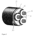
Figure 2 is a perspective view of an embodiment of the invention -
Figures 1 and2 illustrate an embodiment of a cable according to the invention. According to one aspect, the cable is a three core power cable, for transmitting, high, medium or low voltage electrical power. The cable comprises threecores 10 that comprise a conductor, insulation layers and the like, in a manner well known to one skilled in the art of power cables. While particular arrangement of the cores of a three-core power cable is illustrated, the arrangement of the cores may comprise different types and numbers of insulating and functional layers, known to one skilled in the art of power cables - The three
cores 10 are arranged in the center of the cable, and the interstitial zones are filled byplastic fillers 12. The fillers help, inter alia, to maintain the circular cross section of the cable. As seen infigure 1 , the plastic fillers have an interstices-filling portion and a curved outer surface, the curvature of the outer surface corresponding to the curvature of the cable. The interstices-filling portion has two inner, curved surfaces. The inner curved surfaces of adjacent fillers cooperate to form a semi-circular channel in which is arranged a core. In one embodiment, the fillers have a plurality of internal walls forming a honey-combed, cellular structure. The honey-combed structure reduces weight and provides structural integrity for the filler. One skilled in the art of three-core power cables will recognize that different arrangements of fillers may be employed. - An
auxiliary cable 14, for example a fiber optic cable, may be arranged at the interior of the cable. - Surrounding the three cores is a
binder layer 16, and an outerprotective layer 18. Arranged between the binder layer and the outer layer is arranged a plurality ofelongated armor elements 20. According to one aspect of the invention, thearmor elements 20 are elongated plastic filaments or rods, twisted about the cores as shown infigure 2 . The plastic rods are arranged adjacent to one another, such that a protective barrier is formed about the cores. The material and dimensions of the plastic rods are chosen so as to provide impact resistance to the cable for a given application.
Claims (10)
- A power cable, comprising one or more cores (10) comprising a conducting element, a binder layer (16) surrounding the cores, an outer protective layer (18) arranged outside the binder layer, and a twisted layer of elongated plastic rods (20) arranged intermediate the binder layer and the outer layer, the plastic rods forming an impact-resistant armoring layer.
- A power cable according to claim 1, wherein the cable is a three-core power cable.
- A power cable according to claims 1 or 2, wherein the cores are arranged at the center of the cable thereby forming interstitial zones between the cores and the outer covering, the cable further comprising a plurality of filler members (12) arranged in the interstitial zones.
- A power cable according to claim 3, wherein the filler members are elongated plastic elements having an interstice-filling portion and a curved outer surface, the curvature of the outer surface corresponding to the curvature of the cable.
- A power cable according to claim 4, wherein the interstices-filling portions of the filler members have curved inner surfaces, and wherein the curved inner surfaces of adjacent filler members cooperate to form a semi-circular channel in which is arranged a core.
- A power cable according to one of the preceding claims, wherein the filler members have internal walls forming a plurality of cells.
- A power cable according to one of the preceding claims, wherein the cable is a high voltage cable.
- A power cable according to one of the preceding claims, wherein the cable is a medium voltage cable.
- A power cable according to one of the preceding claims, wherein the cable is a low voltage cable.
- A power cable according to one of the preceding claims, wherein the plastic rods are arranged immediately adjacent to one another so as to form a protective barrier.
Priority Applications (1)
| Application Number | Priority Date | Filing Date | Title |
|---|---|---|---|
| EP16305547.8A EP3244423A1 (en) | 2016-05-11 | 2016-05-11 | Three core power cables with plastic armor |
Applications Claiming Priority (1)
| Application Number | Priority Date | Filing Date | Title |
|---|---|---|---|
| EP16305547.8A EP3244423A1 (en) | 2016-05-11 | 2016-05-11 | Three core power cables with plastic armor |
Publications (1)
| Publication Number | Publication Date |
|---|---|
| EP3244423A1 true EP3244423A1 (en) | 2017-11-15 |
Family
ID=56098185
Family Applications (1)
| Application Number | Title | Priority Date | Filing Date |
|---|---|---|---|
| EP16305547.8A Withdrawn EP3244423A1 (en) | 2016-05-11 | 2016-05-11 | Three core power cables with plastic armor |
Country Status (1)
| Country | Link |
|---|---|
| EP (1) | EP3244423A1 (en) |
Cited By (4)
| Publication number | Priority date | Publication date | Assignee | Title |
|---|---|---|---|---|
| WO2020081955A1 (en) * | 2018-10-18 | 2020-04-23 | Saudi Arabian Oil Company | Power cable with non-conductive armor |
| CN113793722A (en) * | 2021-08-21 | 2021-12-14 | 陈万周 | Steel wire armored power cable |
| CN114300193A (en) * | 2021-12-29 | 2022-04-08 | 安徽森联信息科技有限公司 | Composite cable capable of being used simultaneously by combining three networks |
| CN116230299A (en) * | 2023-04-14 | 2023-06-06 | 叶曹世 | Flame-retardant power cable and processing system and processing method thereof |
Citations (7)
| Publication number | Priority date | Publication date | Assignee | Title |
|---|---|---|---|---|
| US3634607A (en) * | 1970-06-18 | 1972-01-11 | Coleman Cable & Wire Co | Armored cable |
| US3980808A (en) * | 1974-09-19 | 1976-09-14 | The Furukawa Electric Co., Ltd. | Electric cable |
| DE2516472B1 (en) | 1975-04-15 | 1976-09-16 | Felten & Guilleaume Carlswerk | Electric high-voltage, high-frequency, impulse submarine cable, especially for deterring sharks |
| GB1497737A (en) | 1974-07-10 | 1978-01-12 | Felten & Guilleaume Kabelwerk | Electric cables with tension-supporting elements |
| WO2012049508A1 (en) * | 2010-10-12 | 2012-04-19 | Artificial Lift Company Limited | Armoured cable for down hole electrical submersible pump |
| EP2515606A2 (en) * | 2011-04-19 | 2012-10-24 | Nexans | Subsea pipeline direct electric heating cable with a protection system |
| WO2014202141A1 (en) * | 2013-06-19 | 2014-12-24 | Abb Technology Ltd | A power cable assembly device and a power cable provided with such a device |
-
2016
- 2016-05-11 EP EP16305547.8A patent/EP3244423A1/en not_active Withdrawn
Patent Citations (7)
| Publication number | Priority date | Publication date | Assignee | Title |
|---|---|---|---|---|
| US3634607A (en) * | 1970-06-18 | 1972-01-11 | Coleman Cable & Wire Co | Armored cable |
| GB1497737A (en) | 1974-07-10 | 1978-01-12 | Felten & Guilleaume Kabelwerk | Electric cables with tension-supporting elements |
| US3980808A (en) * | 1974-09-19 | 1976-09-14 | The Furukawa Electric Co., Ltd. | Electric cable |
| DE2516472B1 (en) | 1975-04-15 | 1976-09-16 | Felten & Guilleaume Carlswerk | Electric high-voltage, high-frequency, impulse submarine cable, especially for deterring sharks |
| WO2012049508A1 (en) * | 2010-10-12 | 2012-04-19 | Artificial Lift Company Limited | Armoured cable for down hole electrical submersible pump |
| EP2515606A2 (en) * | 2011-04-19 | 2012-10-24 | Nexans | Subsea pipeline direct electric heating cable with a protection system |
| WO2014202141A1 (en) * | 2013-06-19 | 2014-12-24 | Abb Technology Ltd | A power cable assembly device and a power cable provided with such a device |
Cited By (7)
| Publication number | Priority date | Publication date | Assignee | Title |
|---|---|---|---|---|
| WO2020081955A1 (en) * | 2018-10-18 | 2020-04-23 | Saudi Arabian Oil Company | Power cable with non-conductive armor |
| CN113793722A (en) * | 2021-08-21 | 2021-12-14 | 陈万周 | Steel wire armored power cable |
| CN113793722B (en) * | 2021-08-21 | 2024-04-09 | 广州市明兴电缆有限公司 | Steel wire armored power cable |
| CN114300193A (en) * | 2021-12-29 | 2022-04-08 | 安徽森联信息科技有限公司 | Composite cable capable of being used simultaneously by combining three networks |
| CN114300193B (en) * | 2021-12-29 | 2024-03-08 | 付国平 | Composite cable capable of being used simultaneously through three-network integration |
| CN116230299A (en) * | 2023-04-14 | 2023-06-06 | 叶曹世 | Flame-retardant power cable and processing system and processing method thereof |
| CN116230299B (en) * | 2023-04-14 | 2023-12-08 | 江苏远方电缆厂有限公司 | Flame-retardant power cable and processing system and processing method thereof |
Similar Documents
| Publication | Publication Date | Title |
|---|---|---|
| US10847286B2 (en) | Metal sheathed cable with jacketed, cabled conductor subassembly | |
| US8088997B2 (en) | Metal sheathed cable assembly | |
| US8658900B2 (en) | Metal sheathed cable assembly | |
| CN101807450B (en) | Sea electric power cable | |
| EP3244422B1 (en) | Three core power cables with surrounding plastic filler | |
| US20170229215A1 (en) | Electrical cable | |
| CN104715842A (en) | Insulated control cable for petrochemical industry | |
| KR20250006774A (en) | Conductor, wire and cable | |
| JP2016167335A (en) | Manufacturing method of power distribution cables and cables | |
| US20170352451A1 (en) | Metal clad cable having parallel laid conductors | |
| CN201725627U (en) | Undersea power cable | |
| EP3043357B1 (en) | Metal sheathed cable with jacketed, cabled conductor subassembly | |
| CN204732188U (en) | The control cables of spiral armouring | |
| CN203910320U (en) | Cold-resistant, twist-resistant and flame-retardant wind energy power cable | |
| CN205656899U (en) | Compound environmental protection cable of multipurpose | |
| CN107068286A (en) | A kind of anti-extrusion armouring power transmission cable | |
| CN104715811A (en) | Acid and alkali resistant cable for petrochemical industry | |
| CN104821194A (en) | Armored shielding flexible cable for coal cutter | |
| CN205158928U (en) | Flexible fire -retardant fireproof cable | |
| CN210245105U (en) | High-reliability and high-strength shielding charging cable of new energy automobile | |
| CN104616767A (en) | Copper-plastic nickel strip armor ethylene-propylene sheath motor leading cable | |
| CN202855373U (en) | Shield compensation wire | |
| CN202996336U (en) | Radio-resisting light copper-conductor control cable | |
| CN205264382U (en) | Anti stretch -proof cable that pulls for computer | |
| CN104715809A (en) | Shielded and armored control cable for mining |
Legal Events
| Date | Code | Title | Description |
|---|---|---|---|
| PUAI | Public reference made under article 153(3) epc to a published international application that has entered the european phase |
Free format text: ORIGINAL CODE: 0009012 |
|
| STAA | Information on the status of an ep patent application or granted ep patent |
Free format text: STATUS: THE APPLICATION HAS BEEN PUBLISHED |
|
| AK | Designated contracting states |
Kind code of ref document: A1 Designated state(s): AL AT BE BG CH CY CZ DE DK EE ES FI FR GB GR HR HU IE IS IT LI LT LU LV MC MK MT NL NO PL PT RO RS SE SI SK SM TR |
|
| AX | Request for extension of the european patent |
Extension state: BA ME |
|
| STAA | Information on the status of an ep patent application or granted ep patent |
Free format text: STATUS: REQUEST FOR EXAMINATION WAS MADE |
|
| 17P | Request for examination filed |
Effective date: 20180403 |
|
| RBV | Designated contracting states (corrected) |
Designated state(s): AL AT BE BG CH CY CZ DE DK EE ES FI FR GB GR HR HU IE IS IT LI LT LU LV MC MK MT NL NO PL PT RO RS SE SI SK SM TR |
|
| STAA | Information on the status of an ep patent application or granted ep patent |
Free format text: STATUS: EXAMINATION IS IN PROGRESS |
|
| 17Q | First examination report despatched |
Effective date: 20181015 |
|
| STAA | Information on the status of an ep patent application or granted ep patent |
Free format text: STATUS: THE APPLICATION IS DEEMED TO BE WITHDRAWN |
|
| 18D | Application deemed to be withdrawn |
Effective date: 20200901 |