EP3244330B1 - Ensemble adaptateur comportant un système de poulie et entraînement à engrenage à vis sans fin permettant d'interconnecter des dispositifs chirurgicaux électromécaniques et des effecteurs d'extrémité chirurgicaux - Google Patents
Ensemble adaptateur comportant un système de poulie et entraînement à engrenage à vis sans fin permettant d'interconnecter des dispositifs chirurgicaux électromécaniques et des effecteurs d'extrémité chirurgicaux Download PDFInfo
- Publication number
- EP3244330B1 EP3244330B1 EP17170006.5A EP17170006A EP3244330B1 EP 3244330 B1 EP3244330 B1 EP 3244330B1 EP 17170006 A EP17170006 A EP 17170006A EP 3244330 B1 EP3244330 B1 EP 3244330B1
- Authority
- EP
- European Patent Office
- Prior art keywords
- cable
- assembly
- gear
- adapter assembly
- capstan
- Prior art date
- Legal status (The legal status is an assumption and is not a legal conclusion. Google has not performed a legal analysis and makes no representation as to the accuracy of the status listed.)
- Active
Links
- 239000012636 effector Substances 0.000 title claims description 66
- 238000010304 firing Methods 0.000 claims description 42
- 230000004044 response Effects 0.000 claims description 10
- 230000000712 assembly Effects 0.000 description 23
- 238000000429 assembly Methods 0.000 description 23
- 230000007246 mechanism Effects 0.000 description 6
- 238000004891 communication Methods 0.000 description 4
- 238000000034 method Methods 0.000 description 4
- 230000003872 anastomosis Effects 0.000 description 3
- 238000004519 manufacturing process Methods 0.000 description 2
- 230000013011 mating Effects 0.000 description 2
- 238000012986 modification Methods 0.000 description 2
- 230000004048 modification Effects 0.000 description 2
- 230000003213 activating effect Effects 0.000 description 1
- 230000008901 benefit Effects 0.000 description 1
- 230000000994 depressogenic effect Effects 0.000 description 1
- 210000005069 ears Anatomy 0.000 description 1
- 230000014759 maintenance of location Effects 0.000 description 1
Images


Classifications
-
- A—HUMAN NECESSITIES
- A61—MEDICAL OR VETERINARY SCIENCE; HYGIENE
- A61B—DIAGNOSIS; SURGERY; IDENTIFICATION
- A61B17/00—Surgical instruments, devices or methods, e.g. tourniquets
- A61B17/068—Surgical staplers, e.g. containing multiple staples or clamps
- A61B17/072—Surgical staplers, e.g. containing multiple staples or clamps for applying a row of staples in a single action, e.g. the staples being applied simultaneously
- A61B17/07207—Surgical staplers, e.g. containing multiple staples or clamps for applying a row of staples in a single action, e.g. the staples being applied simultaneously the staples being applied sequentially
-
- A—HUMAN NECESSITIES
- A61—MEDICAL OR VETERINARY SCIENCE; HYGIENE
- A61B—DIAGNOSIS; SURGERY; IDENTIFICATION
- A61B17/00—Surgical instruments, devices or methods, e.g. tourniquets
- A61B2017/00017—Electrical control of surgical instruments
-
- A—HUMAN NECESSITIES
- A61—MEDICAL OR VETERINARY SCIENCE; HYGIENE
- A61B—DIAGNOSIS; SURGERY; IDENTIFICATION
- A61B17/00—Surgical instruments, devices or methods, e.g. tourniquets
- A61B17/00234—Surgical instruments, devices or methods, e.g. tourniquets for minimally invasive surgery
- A61B2017/00292—Surgical instruments, devices or methods, e.g. tourniquets for minimally invasive surgery mounted on or guided by flexible, e.g. catheter-like, means
- A61B2017/003—Steerable
- A61B2017/00318—Steering mechanisms
- A61B2017/00323—Cables or rods
- A61B2017/00327—Cables or rods with actuating members moving in opposite directions
-
- A—HUMAN NECESSITIES
- A61—MEDICAL OR VETERINARY SCIENCE; HYGIENE
- A61B—DIAGNOSIS; SURGERY; IDENTIFICATION
- A61B17/00—Surgical instruments, devices or methods, e.g. tourniquets
- A61B2017/00367—Details of actuation of instruments, e.g. relations between pushing buttons, or the like, and activation of the tool, working tip, or the like
- A61B2017/00398—Details of actuation of instruments, e.g. relations between pushing buttons, or the like, and activation of the tool, working tip, or the like using powered actuators, e.g. stepper motors, solenoids
-
- A—HUMAN NECESSITIES
- A61—MEDICAL OR VETERINARY SCIENCE; HYGIENE
- A61B—DIAGNOSIS; SURGERY; IDENTIFICATION
- A61B17/00—Surgical instruments, devices or methods, e.g. tourniquets
- A61B2017/0046—Surgical instruments, devices or methods, e.g. tourniquets with a releasable handle; with handle and operating part separable
- A61B2017/00473—Distal part, e.g. tip or head
-
- A—HUMAN NECESSITIES
- A61—MEDICAL OR VETERINARY SCIENCE; HYGIENE
- A61B—DIAGNOSIS; SURGERY; IDENTIFICATION
- A61B17/00—Surgical instruments, devices or methods, e.g. tourniquets
- A61B2017/00477—Coupling
-
- A—HUMAN NECESSITIES
- A61—MEDICAL OR VETERINARY SCIENCE; HYGIENE
- A61B—DIAGNOSIS; SURGERY; IDENTIFICATION
- A61B17/00—Surgical instruments, devices or methods, e.g. tourniquets
- A61B2017/00681—Aspects not otherwise provided for
- A61B2017/00725—Calibration or performance testing
-
- A—HUMAN NECESSITIES
- A61—MEDICAL OR VETERINARY SCIENCE; HYGIENE
- A61B—DIAGNOSIS; SURGERY; IDENTIFICATION
- A61B17/00—Surgical instruments, devices or methods, e.g. tourniquets
- A61B2017/00681—Aspects not otherwise provided for
- A61B2017/00734—Aspects not otherwise provided for battery operated
-
- A—HUMAN NECESSITIES
- A61—MEDICAL OR VETERINARY SCIENCE; HYGIENE
- A61B—DIAGNOSIS; SURGERY; IDENTIFICATION
- A61B17/00—Surgical instruments, devices or methods, e.g. tourniquets
- A61B17/068—Surgical staplers, e.g. containing multiple staples or clamps
- A61B17/072—Surgical staplers, e.g. containing multiple staples or clamps for applying a row of staples in a single action, e.g. the staples being applied simultaneously
- A61B2017/07214—Stapler heads
- A61B2017/07271—Stapler heads characterised by its cartridge
-
- A—HUMAN NECESSITIES
- A61—MEDICAL OR VETERINARY SCIENCE; HYGIENE
- A61B—DIAGNOSIS; SURGERY; IDENTIFICATION
- A61B17/00—Surgical instruments, devices or methods, e.g. tourniquets
- A61B17/28—Surgical forceps
- A61B17/29—Forceps for use in minimally invasive surgery
- A61B2017/2926—Details of heads or jaws
- A61B2017/2927—Details of heads or jaws the angular position of the head being adjustable with respect to the shaft
-
- A—HUMAN NECESSITIES
- A61—MEDICAL OR VETERINARY SCIENCE; HYGIENE
- A61B—DIAGNOSIS; SURGERY; IDENTIFICATION
- A61B90/00—Instruments, implements or accessories specially adapted for surgery or diagnosis and not covered by any of the groups A61B1/00 - A61B50/00, e.g. for luxation treatment or for protecting wound edges
- A61B90/08—Accessories or related features not otherwise provided for
- A61B2090/0803—Counting the number of times an instrument is used
Definitions
- the present disclosure relates to adapter assemblies for use in surgical systems. More specifically, the present disclosure relates to adapter assemblies for use with, and to electrically and mechanically interconnect, electromechanical surgical devices and surgical end effectors, and to surgical systems including handheld electromechanical surgical devices and adapter assemblies for connecting surgical end effectors to the handheld electromechanical surgical devices.
- the surgical devices include a powered handle assembly, which is reusable, and a disposable end effector or the like that is selectively connected to the powered handle assembly prior to use and then disconnected from the end effector following use in order to be disposed of or in some instances, sterilized for re-use.
- end effectors for use with many of the existing powered surgical devices and/or handle assemblies are driven by a linear force.
- end effectors for performing endo-gastrointestinal anastomosis procedures, end-to-end anastomosis procedures and transverse anastomosis procedures each typically require a linear driving force in order to be operated.
- end effectors are not compatible with surgical devices and/or handle assemblies that use a rotary motion to deliver power or the like.
- adapters and/or adapter assemblies are used to interface between and interconnect the linear driven end effectors with the powered rotary driven surgical devices and/or handle assemblies.
- Many of these adapter and/or adapter assemblies are complex devices including many parts and requiring extensive labor to assemble.
- Adapter concepts often include a cable system for distal rotation and/or articulation.
- Some designs of cable systems include pulleys or lead screws with counter-directional threads to generate linear motion. Consistent with stroke dynamics, lead screw designs can require additional length to accommodate coordinated cable take-up and release. By comparison, pulley designs can be more compact than lead screw designs, but typically require different considerations including those associated with assembly and tensioning.
- an adapter assembly selectively interconnects an end effector that is configured to perform a function and a surgical device that is configured to operate the end effector.
- the adapter assembly includes an outer tube having a distal end and a proximal end, a housing secured to the proximal end of the outer tube, and a cable drive assembly supported by the housing.
- the cable drive assembly includes a worm gear, a cable gear coupled to the worm gear and rotatable in response to rotation of the worm gear, a capstan coupled to the cable gear and rotatable in response to rotation of the cable gear, and a cable coupled to the capstan.
- the cable may be axially translatable in response rotation of the capstan to actuate a function of the end effector while connected to the distal end of the outer tube.
- the cable drive assembly may include a second worm gear, a second cable gear coupled to the second worm gear, a second capstan coupled to the second cable gear, and a second cable coupled to the second capstan.
- the second cable may be axially translatable in response to rotation of one or more of the second worm gear, the second cable gear, and the second capstan.
- the cable drive assembly may further include one or more pulleys supporting the cable and configured to direct the cable into the outer tube.
- the cable drive assembly may further include a body portion that supports the worm gear and the cable gear in contacting relation with one another.
- the adapter assembly may further include a firing assembly that extends through the cable drive assembly and into the outer tube.
- the firing assembly may include a firing shaft that rotates independent of the cable drive assembly to actuate a firing function of the end effector.
- the housing of the adapter assembly may include an outer housing and an inner housing that support the cable drive assembly therein.
- the outer tube defines a longitudinal axis that extends between the proximal and distal ends of the outer tube.
- the worm gear may be supported on a shaft member that extends in parallel relationship to the longitudinal axis of the outer tube.
- the shaft member may be rotatable to rotate the worm gear.
- a surgical stapling apparatus includes an end effector, a surgical device configured to operate the end effector, and an adapter assembly for selectively interconnecting the end effector and the surgical device.
- the adapter assembly of the surgical stapling apparatus includes an outer tube having a distal end and a proximal end, a housing secured to the proximal end of the outer tube, and a cable drive assembly supported by the housing.
- the cable drive assembly includes a worm gear, a cable gear coupled to the worm gear, a capstan coupled to the cable gear, and a cable coupled to the capstan.
- the cable may be axially translatable in response rotation of one or more of the worm gear, the cable gear, and the capstan.
- the adapter assembly of the surgical stapling apparatus may further include a firing assembly that extends through the cable drive assembly and into the outer tube.
- the firing assembly may include a firing shaft that rotates independent of the cable drive assembly to actuate a firing function of the end effector.
- the cable drive assembly may further include a second worm gear, a second cable gear coupled to the second worm gear, a second capstan coupled to the second cable gear, and a second cable coupled to the second capstan.
- the second cable may be axially translatable in response to rotation of one or more of the second worm gear, the second cable gear, and the second capstan.
- the housing of the adapter assembly may include an outer housing and an inner housing.
- the inner and outer housings may support the cable drive assembly therein.
- the cable drive assembly may further include one or more pulleys supporting the cable and configured to direct the cable into the outer tube.
- the cable drive assembly may further include a body portion that supports the worm gear and the cable gear in contacting relation with one another.
- the outer tube of the adapter assembly defines a longitudinal axis that extends between the proximal and distal ends of the outer tube.
- the worm gear may be supported on a shaft member that extends in parallel relationship to the longitudinal axis of the outer tube.
- the shaft member may be rotatable to rotate the worm gear.
- an adapter assembly for selective connection to a surgical device.
- the adapter assembly includes an outer tube having a distal end and a proximal end, a housing secured to the proximal end of the outer tube, and a cable drive assembly supported by the housing.
- the cable drive assembly includes a worm gear drive assembly, a cable gear assembly coupled to the worm gear drive assembly, and one or more cables coupled to the cable gear assembly and axially translatable within the outer tube.
- the cable drive assembly may further include a second worm gear, a second cable gear coupled to the second worm gear, a second capstan coupled to the second cable gear, and a second cable coupled to the second capstan.
- Electromechanical surgical systems of the present disclosure include surgical devices in the form of powered handheld electromechanical instruments configured for selective attachment to a plurality of different end effectors that are each configured for actuation and manipulation by the powered handheld electromechanical surgical instrument.
- the presently described electromechanical surgical systems include adapter assemblies that interconnect the powered handheld electromechanical surgical instruments to the plurality of different end effectors.
- Each adapter assembly includes an articulation assembly and a firing assembly that is operatively coupled to a powered handheld electromechanical surgical instrument for effectuating actuation and/or manipulation of the plurality of different end effectors.
- distal refers to that portion of the system, assembly, device, and/or component thereof, farther from the user
- proximal refers to that portion of the system, assembly, device, and/or component thereof, closer to the user.
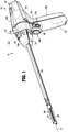
- an electromechanical surgical system in accordance with the present disclosure, generally referred to as 10, includes a surgical device 100 in the form of a powered handheld electromechanical instrument, an adapter assembly 200, and a surgical loading unit (e.g., multiple- or single-use loading unit) or end effector 300.
- Surgical device 100 is configured for selective connection with adapter assembly 200, and, in turn, adapter assembly 200 is configured for selective connection with end effector 300. Together, surgical device 100 and adapter assembly 200 may cooperate to actuate end effector 300.
- Surgical device 100 of electromechanical surgical system 10 includes a handle housing 102 including a controller or circuit board (not shown) and a drive mechanism 106 situated therein.
- the circuit board is configured to control the various operations of surgical device 100.
- Handle housing 102 defines a cavity therein (not shown) for selective removable receipt of a rechargeable battery 103 therein.
- the battery 103 is configured to supply power to any electrical components of surgical device 100.
- the drive mechanism 106 within the handle housing 102 is configured to drive rotatable shafts 106a-106c (and/or gear components - not shown) within handle housing 102 in order to perform the various operations of surgical device 100.
- drive mechanism 106 (and/or components thereof) is operable to selectively articulate end effector 300 about a longitudinal axis "X" and relative to a distal end of adapter assembly 200, to selectively rotate end effector 300 about longitudinal axis "X” and relative to handle housing 102, to selectively move/approximate/separate an anvil assembly 310 and a cartridge assembly 320 of end effector 300 relative to one another, and/or to fire a stapling and cutting cartridge within cartridge assembly 320 of end effector 300.
- Handle housing 102 of surgical device 100 includes an upper housing portion 102a that houses various components of surgical device 100, and a lower hand grip portion 102b extending from upper housing portion 102a.
- Lower hand grip portion 102b of handle housing 102 may be disposed distally of a proximal-most end of upper housing portion 102a of handle housing 102. The location of lower hand grip portion 102b relative to upper housing portion 102a is selected to balance a weight of surgical device 100 while surgical device 100 is connected to or supports adapter assembly 200 and/or end effector 300.
- connection portion 104 of handle housing 102 is configured to secure to a proximal end of adapter assembly 200.
- Connection portion 104 houses an articulation contact surface 105 in electrical communication with the circuit board (not shown) of surgical device 100 to control drive mechanism 106.
- Each rotatable drive shaft 106a-106c of drive mechanism 106 can be independently, and/or dependently, actuatable and rotatable.
- rotatable drive shafts, 106a, 106b, and 106c may be arranged in a common plane or line with one another. As can be appreciated, any number of rotatable drive shafts can be arranged in any suitable configuration.
- Handle housing 102 of surgical device 100 supports finger-actuated control buttons, rocker devices, and/or the like for activating various functions of surgical device 100.
- handle housing 102 may support actuators including an actuation pad 108 in operative registration with sensors 108a that cooperate with actuation pad 108 to effectuate, for instance, opening, closing, and/or firing of end effector 300.
- Handle housing 102 can support actuators 107a, 107b which can be disposed in electrical communication with one or more motors (not shown) of drive mechanism 106 to effectuate rotation of rotatable drive shafts 106a, 106b, and/or 106c for actuation thereof to enable adjustment of one or more of the components of adapter assembly 200.
- Any of the presently described actuators can have any suitable configuration (e.g., button, knob, toggle, slide, etc.).
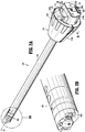
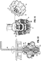
- adapter assembly 200 of electromechanical surgical system 10 includes a housing 202 at a proximal end portion thereof and an outer tube 204 that extends distally from housing 202 along longitudinal axis "X" to a distal end portion 206.
- Distal end portion 206 of outer tube 204 couples a distal end of adapter assembly 200 to a proximal end of end effector 300.
- the distal end portion may support a gimbal or the like that couple to an articulation assembly such as the articulation or cable drive assembly described herein to enable end effectors, such as end effector 300 of electromechanical surgical system 10, to articulate relative to adapter assembly 200 of electromechanical surgical system 10.
- Such distal end portions 206 may support a rotatable gear 206a that engages with a proximal end of end effector 300 to effectuate a firing thereof as described in greater detail below.
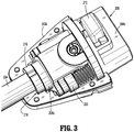
- housing 202 of adapter assembly 200 includes an inner housing 202a and an outer housing 202b having first and second housing halves 202c, 202d.
- Inner housing 202a includes a housing body 208 having a proximal housing body 208a and a distal housing body 208b that couple together via fastener-receiving arms 208c, 208d of proximal housing body 208a and fastener-receiving ears 208e, 208f of distal housing body 208b.
- Proximal housing body 208a of inner housing 202a supports an electrical assembly 209 therein and a mounting assembly 210 thereon.
- Electrical assembly 209 of housing 202 may include a circuit board with contact pins 209a for electrical connection to a corresponding electrical plug (not shown) disposed in connection portion 104 of surgical device 100 (e.g., for calibration and communication of life-cycle information to the circuit board of the surgical device 100).
- Mounting assembly 210 of housing 202 includes a mounting button 212 that is biased in an extended position and is configured to be depressed downwardly to a compressed position. In the compressed position, mounting button 212 is disposed in close approximation with housing body 208 of inner housing 202a and offset from the extended position thereof. Mounting button 212 includes sloped engagement features 212a that are configured to contact connection portion 104 ( FIG. 1 ) of handle housing 102 while mounting button 212 is in the extended position to facilitate securement of housing 202 of adapter assembly 200 to connection portion 104 of handle housing 102.
- connection portion 104 FIG. 1
- Outer housing 202b of housing 202 is disposed around inner housing 202a of housing 202 to support an articulation or cable drive assembly 220 and a firing assembly 230 within housing 202 of adapter assembly 200.
- Distal housing body 208b of inner housing 208 includes a distal shaft 214a that is received within a proximal end of outer tube 204 and coupled thereto by a bearing 216 mounted within a channel 218 defined within outer housing 202b of housing 202.
- distal housing body 208b further includes mirrored arms 214b, 214c each defining a U-shaped passage 214d.
- U-shaped passages 214d of distal housing body 208b extend through arms 214b, 214c of distal housing body 208b and are configured to receive first and second cable gear assemblies 224, 225 of cable drive assembly 220 therein.
- Distal housing body 208b also includes pins or bosses 214e, 214f that extend proximally from a proximal surface of distal housing body 208b. The proximal surface of distal housing body 208b also defines distal pulley recesses 214g-214j therein.
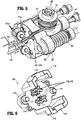
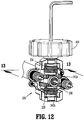
- cable drive assembly 220 includes a body portion 222, a first cable gear assembly 224, a second cable gear assembly 225, a first worm gear drive assembly 226, and a second worm gear drive assembly 227, proximal guide pulleys 228a-228d, and distal guide pulleys 229a-229d.
- Body portion 222 of cable drive assembly 220 defines proximal pulley recesses 222a-222d that receive respective proximal guide pulleys 228a-228d therein to enable the respective proximal guide pulleys 228a-228d to rotate therein as cables 240a, 240b of cable drive assembly 220 rotate around respective proximal guide pulleys 228a-228d to manipulate end effector 300.
- distal guide pulleys 229a-229d of cable drive assembly 220 are received within respective distal pulley recesses 214g-214j of distal housing body 208b of inner housing 202a to enable distal guide pulleys 229a-229d to rotate therein as cables 240a, 240b of cable drive assembly 220 rotate around respective distal guide pulleys 229a-229d to manipulate end effector 300.
- Body portion 222 of cable drive assembly 220 includes an upper mounting projection 222e extending therefrom and positioned to partially receive first cable gear assembly 224 of cable drive assembly 220 therein for supporting first cable gear assembly 224 on upper mounting projection 222e of body portion 222.
- a lower mounting projection 222f also extends from body portion 222 of cable drive assembly 220 in a direction opposite upper mounting projection 222e of body portion 222.
- Lower mounting projection 222f of body portion 222 is positioned to support second cable gear assembly 225 of cable drive assembly 220 thereon.
- Body portion 222 of cable drive assembly 220 further defines worm gear recesses 222g, 222h therein that rotatably receive first and second worm drive assemblies 226, 227, respectively in a proximal end thereof and pins 214e, 214f of distal housing body 208b in a distal end thereof.
- a firing shaft passage 222i is defined centrally through body portion 222 to receive a firing assembly 230 therein.
- first cable gear assembly 224 of cable drive assembly 220 includes an upper gear 224a, an upper capstan 224b supported on upper gear 224a, and an upper fastener 224c that couples upper capstan 224b to upper gear 224a while upper capstan 224b is coupled to upper mounting projection 222e of body portion 222 of cable drive assembly 220.
- second cable gear assembly 225 which mirrors first cable gear assembly 224, includes a lower gear 225a, a lower capstan 225b supported on lower gear 225a, and a lower fastener 225c that couples lower capstan 225b to lower gear 225a while lower capstan 225b is coupled to lower mounting projection 222f of body portion 222 of cable drive assembly 220.
- Each of upper and lower gears 224a, 225a of respective first and second gear assemblies 224, 225 include a center protuberance 2245 that is received in respective upper and lower mounting projections 222e, 222f of body portion 222 to enable respective first and second gear assemblies 224, 225 to rotate about respective upper and lower mounting projections 222e, 222f of body portion 222.
- First and second cables 240a, 240b are wound around respective upper and lower capstans 224b, 225b and around respective proximal and distal guide pulleys 228a-228d, 229a-229d so that opposite ends/sides of each of the respective cables 240a, 240b extends distally through outer tube 204 to operatively couple to end effector 300 (e.g., to effectuate rotation and/or articulation thereof).
- First worm gear drive assembly 226 of cable drive assembly 220 includes a first worm drive 226a rotatably supported between bearings 226b, 226c.
- First worm drive 226a includes a worm gear 226d secured on a shaft member 226e.
- Shaft member 226e has a proximal driving end 226f received in bearing 226b and a distal end 226g received in bearing 226c.
- second worm gear drive assembly 227 of cable drive assembly 220 includes a first worm drive 227a rotatably supported between bearings 227b, 227c.
- Second worm drive 227a includes a worm gear 227d secured on a shaft member 227e.
- Shaft member 227e has a proximal driving end 227f received in bearing 227b and a distal end 227g received in bearing 227c.
- firing assembly 230 of adapter assembly 200 includes a firing shaft 232, a bearing 234 supported on firing shaft 232, and an input socket 236 secured to a proximal end 232a of firing shaft 232.
- Firing shaft 232 of firing assembly 230 includes spaced collars 232b, 232c and a distal driving end 232d.
- Collar 232b of firing shaft 232 supports bearing 234 thereon and collar 232c of firing shaft 232 supports firing shaft 232 against distal housing body 208b of inner housing 202a.
- Distal driving end 232d of firing shaft 232 is extends to distal end portion 206 of outer tube 204 to effectuate a firing of end effector 300 as described in greater detail below.
- End effector 300 includes an anvil 310 and a cartridge assembly 320 that are pinned together by pins 315a, 315b and movable between open and closed conditions.
- Anvil 310 and cartridge assembly 320 cooperate to apply linear rows of fasteners "F” (e.g., staples).
- fasteners "F” are of various sizes, and, in certain embodiments, fasteners "F” are loaded into various lengths or rows of cartridge assembly 320 of end effector 300 (e.g., about 30, 45 and 60 mm in length).
- Cartridge assembly 320 of end effector 300 includes a base 322 secured to a mounting portion 324, a frame portion 326, and a cartridge portion 328.
- Cartridge portion 328 has a tissue engaging surface that defines fastener retaining slots 328a and a knife slot 328b therein.
- Mounting portion 324 of cartridge assembly 320 has mating surfaces 324a, 324b on a proximal end thereof and defines a receiving channel 324c therein that supports frame portion 326, cartridge portion 328, and a fastener firing assembly 330 therein.
- Cartridge assembly 320 supports a biasing member 340 (e.g., a leaf spring) that engages anvil 310.
- a biasing member 340 e.g., a leaf spring
- Fastener firing assembly 330 of end effector 300 includes an electrical contact member 332 for electrical communication with the circuit board of surgical device 100, a bearing member 334, a gear member 336 that engages rotatable gear 206a of adapter assembly 200, and a screw assembly 338.
- Screw assembly 338 of fastener firing assembly 330 includes a lead screw 338a, a drive beam 338b, and an actuation sled 338c that is engagable with pusher members 338d.
- Cartridge assembly 320 of end effector 300 also supports plunger assemblies 350a, 350b.
- Each of plunger assemblies 350a, 350b includes a spring 352, a plunger 354, and a pin 356 that secures each plunger assembly to mounting portion 324 of cartridge assembly 320.
- Plunger assemblies 350a, 350b cooperate with the proximal end of cartridge portion 328 to facilitate securement of cartridge portion 328 within mounting portion 324.
- the proximal end of end effector 300 is aligned with distal end portion 206 of adapter assembly 200 so that the proximal end of end effector 300 can be coupled to distal end portion 206 of adapter assembly 200 such that mating surfaces 324a and 324b of end effector 300 engage with distal end portion 206 of adapter assembly 200 and the teeth of gear member 336 of end effector 300 enmesh with the teeth of rotatable gear 206a of distal end portion 206 of adapter assembly 200.
- actuation pad 108 of surgical device 100 is actuated to rotate one or both of rotatable drive shafts 106a, 106c (e.g., clockwise and/or counterclockwise) of surgical device 100 via motors (not shown) disposed within surgical device 100.
- Rotation of rotatable drive shaft 106a of surgical device 100 causes a corresponding rotation of worm gear 227d of worm drive assembly 227 and thus, rotation of lower gear 225a of gear assembly 225.
- Rotation of lower gear 225a of gear assembly 225 rotates lower capstan 225b of gear assembly 225 to draw/retract/tighten one side/end of cable 240a of cable drive assembly 220 while letting out/releasing the opposite side/end of cable 240a.
- rotation of rotatable drive shaft 106c of surgical device 100 causes a corresponding rotation of worm gear 226d of worm drive assembly 226 and thus, rotation of upper gear 224a of gear assembly 226.
- actuation pad 108 of surgical device 100 is actuated to rotate rotatable drive shaft 106b via a motor 103a (see FIG. 1 ) within handle housing 102, and to effectuate rotation of firing shaft 232 of firing assembly 230 about longitudinal axis "X" of adapter assembly 200.
- Rotation of firing shaft 232 of firing assembly 230 rotates rotatable gear 206a of distal end portion 206 of adapter assembly 200, which in turn, causes rotation of gear member 336 of end effector 300.
- Rotation of gear member 336 of firing assembly 330 rotates lead screw 338a of firing assembly 330 and enables drive beam 338b of firing assembly 330 to axially advance along lead screw 338a and through longitudinal knife slot 328b of cartridge portion 328 by virtue of a threaded engagement between lead screw 338a and drive beam 338b.
- Drive beam 338b of firing assembly 330 engages anvil 310 of end effector 300 to maintain anvil 310 and cartridge assembly 320 of end effector 300 in approximation.
- Distal advancement of drive beam 338b of firing assembly 330 advances actuation sled 338c of firing assembly 330 into engagement with pusher members 338d of end effector 300 and fires the fasteners "F" from fastener retention slots 328a of cartridge portion 328 for forming against corresponding fastener forming pockets (not shown) defined within anvil 310.
- End effector 300 can be reset and cartridge portion 328 of cartridge assembly 320 can be replaced so that end effector 300 can then be re-fired as needed or desired.
- upper capstan 224b of first cable gear assembly 224 defines a slot 224d therein and lower capstan 225b of second cable gear assembly 225 defines a slot 225d therein.
- Slots 224d, 225d of respective upper and lower capstans 224b, 225b are configured to selectively receive detents 402 of a rotatable knob 400 therein to enable tension in cables 240a, 240b to be adjusted upon rotation of upper and/or lower capstans 224b, 225b via rotation of rotatable knob 400.
- Rotatable knob 400 further defines a central channel 404 therethrough configured to selectively receive a fastener driver 500 (e.g., an Allen wrench) therethrough for tightening and/or loosening respective upper and lower fasteners 224c, 225c of respective first and second gear assemblies 224, 225 to further facilitate tension adjustments as needed or desired.
- a fastener driver 500 e.g., an Allen wrench
Claims (9)
- Ensemble adaptateur (200) permettant d'interconnecter de manière sélective un effecteur d'extrémité (300) qui est conçu pour exécuter une fonction et un dispositif chirurgical (100) qui est conçu pour faire fonctionner l'effecteur d'extrémité (300), l'ensemble adaptateur (200) comprenant :un tube extérieur (204) ayant une extrémité distale (206) et une extrémité proximale ;un boîtier (202) fixé à l'extrémité proximale du tube extérieur (204) ; etun ensemble d'entraînement à câble (220) supporté par le boîtier (202) et comprenant :un engrenage à vis sans fin (227d) ;un engrenage à câble (224a) accouplé à l'engrenage à vis sans fin (227d) et pouvant tourner en réaction à la rotation de l'engrenage à vis sans fin (227d) ;un cabestan (224b) accouplé à l'engrenage à câble (224a) et pouvant tourner en réaction à la rotation de l'engrenage à câble (224a) ; etun câble (240a) accouplé au cabestan (224b), le câble (240a) pouvant être translaté axialement en réaction à la rotation du cabestan (224b) pour actionner une fonction de l'effecteur d'extrémité (300) tout en étant connecté à l'extrémité distale (206) du tube extérieur (204), caractérisé en ce quel'ensemble d'entraînement à câble (220) comprend en outre une seconde vis sans fin (226d), un second engrenage à câble (225a) accouplé au second engrenage à vis sans fin (226d), un second cabestan (225b) accouplé au second engrenage à câble (225a), et un second câble (240b) accouplé au second cabestan (225b), dans lequel le second câble (240b) peut être translaté axialement en réaction à la rotation du second engrenage à vis sans fin (226d) et/ou du second engrenage à câble (225a) et/ou du second cabestan (225b),dans lequel le cabestan (224b) du premier engrenage à câble (224a) définit une fente (224d) dans celui-ci et le cabestan (225b) du second engrenage à câble (225a) définit une fente (225d) dans celui-ci, lesdites fentes (224d, 225d) étant conçues pour recevoir de manière sélective les crans (402) d'un bouton rotatif (400) à l'intérieur de celles-ci afin de permettre le réglage de la tension des câbles (240a, 240b) lors de la rotation des cabestans (224b, 225b) par l'intermédiaire de la rotation du bouton rotatif (400).
- Ensemble adaptateur (200) selon la revendication 1, dans lequel le bouton rotatif (400) définit en outre un canal central (404) à travers celui-ci, lequel canal central est conçu pour recevoir de manière sélective un entraînement de fixation (500) à travers celui-ci pour serrer et/ou desserrer les fixations supérieure et inférieure (224c, 225c) respectives qui s'accouplent aux cabestans (224b, 224b) pour faciliter davantage les réglages de tension.
- Ensemble adaptateur (200) selon la revendication 1 ou 2, comprenant en outre un ensemble de mise à feu (230) qui s'étend à travers l'ensemble d'entraînement à câble (220) et dans le tube extérieur (204).
- Ensemble adaptateur (200) selon la revendication 3, dans lequel l'ensemble de mise à feu (230) comprend un arbre de mise à feu (232) qui tourne indépendamment de l'ensemble d'entraînement à câble (220) pour actionner une fonction de mise à feu de l'effecteur d'extrémité (300).
- Ensemble adaptateur (200) selon l'une quelconque des revendications précédentes, dans lequel le boîtier (202) comprend un boîtier extérieur (202b) et un boîtier intérieur (202a), les boîtiers intérieur et extérieur (202a, 202b) supportant l'ensemble d'entraînement à câble (220) à l'intérieur de ceux-ci.
- Ensemble adaptateur (200) selon l'une quelconque des revendications précédentes, dans lequel l'ensemble d'entraînement à câble (220) comprend en outre au moins une poulie (228a-d, 229a-d) supportant les câbles (240a, 240b) et conçue pour diriger les câbles (240a, 240b) dans le tube extérieur (204).
- Ensemble adaptateur (200) selon l'une quelconque des revendications précédentes, dans lequel l'ensemble d'entraînement à câble (220) comprend en outre une partie de corps (222) qui supporte les engrenages à vis sans fin (226d, 227d) et les engrenages à câble (224a, 225a) en relation de contact les uns avec les autres.
- Ensemble adaptateur (200) selon l'une quelconque des revendications précédentes, dans lequel le tube extérieur (204) définit un axe longitudinal qui s'étend entre les extrémités proximale et distale (206) du tube extérieur, et dans lequel les engrenages à vis sans fin (226d, 227d) sont supportés par des éléments d'arbre (226e, 227e) qui s'étendent parallèlement à l'axe longitudinal du tube extérieur (204), les éléments d'arbre (226e, 227e) pouvant tourner pour faire tourner les engrenages à vis sans fin (226d, 227d).
- Appareil d'agrafage chirurgical, comprenant :un effecteur d'extrémité (300) ;un dispositif chirurgical conçu pour actionner l'effecteur d'extrémité (300) ; etun ensemble adaptateur (200) selon l'une quelconque des revendications précédentes.
Applications Claiming Priority (2)
| Application Number | Priority Date | Filing Date | Title |
|---|---|---|---|
| US201662333584P | 2016-05-09 | 2016-05-09 | |
| US15/491,046 US20170323578A1 (en) | 2016-05-04 | 2017-04-19 | Systems and methods for simulating prior use of a surgical instrument based on obtained surgical instrument data |
Publications (3)
| Publication Number | Publication Date |
|---|---|
| EP3244330A2 EP3244330A2 (fr) | 2017-11-15 |
| EP3244330A3 EP3244330A3 (fr) | 2017-12-27 |
| EP3244330B1 true EP3244330B1 (fr) | 2020-04-29 |
Family
ID=58672532
Family Applications (1)
| Application Number | Title | Priority Date | Filing Date |
|---|---|---|---|
| EP17170006.5A Active EP3244330B1 (fr) | 2016-05-09 | 2017-05-08 | Ensemble adaptateur comportant un système de poulie et entraînement à engrenage à vis sans fin permettant d'interconnecter des dispositifs chirurgicaux électromécaniques et des effecteurs d'extrémité chirurgicaux |
Country Status (2)
| Country | Link |
|---|---|
| EP (1) | EP3244330B1 (fr) |
| CN (2) | CN113812993A (fr) |
Families Citing this family (3)
| Publication number | Priority date | Publication date | Assignee | Title |
|---|---|---|---|---|
| US10952800B2 (en) * | 2019-04-26 | 2021-03-23 | Covidien Lp | Articulation assembly for a surgical instrument such as for use in a robotic surgical system and methods of assembling the same |
| CN113017835B (zh) * | 2019-12-25 | 2022-11-11 | 杭州术创机器人有限公司 | 用于手术工具组件的线缆张紧装置 |
| DE102021119535B3 (de) | 2021-07-28 | 2022-10-27 | Karl Storz Se & Co. Kg | Chirurgisches Instrument mit Hub-Dreh-Getriebe |
Family Cites Families (12)
| Publication number | Priority date | Publication date | Assignee | Title |
|---|---|---|---|---|
| US10588629B2 (en) | 2009-11-20 | 2020-03-17 | Covidien Lp | Surgical console and hand-held surgical device |
| US8006885B2 (en) * | 2007-04-09 | 2011-08-30 | Tyco Healthcare Group Lp | Surgical stapling apparatus with powered retraction |
| AU2008302039B2 (en) | 2007-09-21 | 2013-07-18 | Covidien Lp | Surgical device |
| US8573465B2 (en) * | 2008-02-14 | 2013-11-05 | Ethicon Endo-Surgery, Inc. | Robotically-controlled surgical end effector system with rotary actuated closure systems |
| US8011551B2 (en) * | 2008-07-01 | 2011-09-06 | Tyco Healthcare Group Lp | Retraction mechanism with clutch-less drive for use with a surgical apparatus |
| US8258526B2 (en) * | 2008-07-03 | 2012-09-04 | Samsung Led Co., Ltd. | Light emitting diode package including a lead frame with a cavity |
| US9259274B2 (en) * | 2008-09-30 | 2016-02-16 | Intuitive Surgical Operations, Inc. | Passive preload and capstan drive for surgical instruments |
| US20140001234A1 (en) * | 2012-06-28 | 2014-01-02 | Ethicon Endo-Surgery, Inc. | Coupling arrangements for attaching surgical end effectors to drive systems therefor |
| US9918713B2 (en) | 2013-12-09 | 2018-03-20 | Covidien Lp | Adapter assembly for interconnecting electromechanical surgical devices and surgical loading units, and surgical systems thereof |
| US9918730B2 (en) * | 2014-04-08 | 2018-03-20 | Ethicon Llc | Methods and devices for controlling motorized surgical devices |
| US10080552B2 (en) | 2014-04-21 | 2018-09-25 | Covidien Lp | Adapter assembly with gimbal for interconnecting electromechanical surgical devices and surgical loading units, and surgical systems thereof |
| US10508720B2 (en) * | 2016-01-21 | 2019-12-17 | Covidien Lp | Adapter assembly with planetary gear drive for interconnecting electromechanical surgical devices and surgical loading units, and surgical systems thereof |
-
2017
- 2017-05-08 EP EP17170006.5A patent/EP3244330B1/fr active Active
- 2017-05-09 CN CN202111186169.7A patent/CN113812993A/zh active Pending
- 2017-05-09 CN CN201710321817.2A patent/CN107440758B/zh active Active
Non-Patent Citations (1)
| Title |
|---|
| None * |
Also Published As
| Publication number | Publication date |
|---|---|
| EP3244330A2 (fr) | 2017-11-15 |
| CN113812993A (zh) | 2021-12-21 |
| CN107440758A (zh) | 2017-12-08 |
| CN107440758B (zh) | 2021-10-29 |
| EP3244330A3 (fr) | 2017-12-27 |
Similar Documents
| Publication | Publication Date | Title |
|---|---|---|
| US11911013B2 (en) | Interconnecting electromechanical surgical devices and surgical loading units, and surgical systems thereof | |
| US10508720B2 (en) | Adapter assembly with planetary gear drive for interconnecting electromechanical surgical devices and surgical loading units, and surgical systems thereof | |
| US11864763B2 (en) | Adapter assembly with pulley system and worm gear drive for interconnecting electromechanical surgical devices and surgical end effectors | |
| US20220225974A1 (en) | Adapter assembly with gimbal for interconnecting electromechanical surgical devices and surgical loading units, and surgical systems thereof | |
| US10085752B2 (en) | Apparatus for endoscopic procedures | |
| CN109620332B (zh) | 手术装置和用于机械接合动力手术器械的接合器 | |
| EP2891459B1 (fr) | Mécanisme de rétention à verrou rotatif d'entraînement direct d'un adaptateur | |
| CN105212978B (zh) | 用于将手术装载单元与手柄组件互连的接合器组件 | |
| US8647258B2 (en) | Apparatus for endoscopic procedures | |
| EP2606812B1 (fr) | Appareil pour procédures endoscopiques | |
| US20110021871A1 (en) | Laparoscopic surgical instrument | |
| EP3244330B1 (fr) | Ensemble adaptateur comportant un système de poulie et entraînement à engrenage à vis sans fin permettant d'interconnecter des dispositifs chirurgicaux électromécaniques et des effecteurs d'extrémité chirurgicaux | |
| EP3184057B1 (fr) | Dispositifs chirurgicaux électromécaniques ayant des entraînements à moteur unique et ensembles d'adaptateurs associés | |
| JP6858954B2 (ja) | 内視鏡システム |
Legal Events
| Date | Code | Title | Description |
|---|---|---|---|
| PUAI | Public reference made under article 153(3) epc to a published international application that has entered the european phase |
Free format text: ORIGINAL CODE: 0009012 |
|
| STAA | Information on the status of an ep patent application or granted ep patent |
Free format text: STATUS: THE APPLICATION HAS BEEN PUBLISHED |
|
| AK | Designated contracting states |
Kind code of ref document: A2 Designated state(s): AL AT BE BG CH CY CZ DE DK EE ES FI FR GB GR HR HU IE IS IT LI LT LU LV MC MK MT NL NO PL PT RO RS SE SI SK SM TR |
|
| AX | Request for extension of the european patent |
Extension state: BA ME |
|
| PUAL | Search report despatched |
Free format text: ORIGINAL CODE: 0009013 |
|
| AK | Designated contracting states |
Kind code of ref document: A3 Designated state(s): AL AT BE BG CH CY CZ DE DK EE ES FI FR GB GR HR HU IE IS IT LI LT LU LV MC MK MT NL NO PL PT RO RS SE SI SK SM TR |
|
| AX | Request for extension of the european patent |
Extension state: BA ME |
|
| RIC1 | Information provided on ipc code assigned before grant |
Ipc: A61B 17/072 20060101AFI20171120BHEP |
|
| STAA | Information on the status of an ep patent application or granted ep patent |
Free format text: STATUS: REQUEST FOR EXAMINATION WAS MADE |
|
| 17P | Request for examination filed |
Effective date: 20180615 |
|
| RBV | Designated contracting states (corrected) |
Designated state(s): AL AT BE BG CH CY CZ DE DK EE ES FI FR GB GR HR HU IE IS IT LI LT LU LV MC MK MT NL NO PL PT RO RS SE SI SK SM TR |
|
| REG | Reference to a national code |
Ref country code: DE Ref legal event code: R079 Ref document number: 602017015498 Country of ref document: DE Free format text: PREVIOUS MAIN CLASS: G06F0019000000 Ipc: A61B0017072000 |
|
| GRAP | Despatch of communication of intention to grant a patent |
Free format text: ORIGINAL CODE: EPIDOSNIGR1 |
|
| STAA | Information on the status of an ep patent application or granted ep patent |
Free format text: STATUS: GRANT OF PATENT IS INTENDED |
|
| RIC1 | Information provided on ipc code assigned before grant |
Ipc: A61B 17/29 20060101ALN20191119BHEP Ipc: A61B 17/072 20060101AFI20191119BHEP |
|
| INTG | Intention to grant announced |
Effective date: 20191205 |
|
| GRAS | Grant fee paid |
Free format text: ORIGINAL CODE: EPIDOSNIGR3 |
|
| GRAA | (expected) grant |
Free format text: ORIGINAL CODE: 0009210 |
|
| STAA | Information on the status of an ep patent application or granted ep patent |
Free format text: STATUS: THE PATENT HAS BEEN GRANTED |
|
| AK | Designated contracting states |
Kind code of ref document: B1 Designated state(s): AL AT BE BG CH CY CZ DE DK EE ES FI FR GB GR HR HU IE IS IT LI LT LU LV MC MK MT NL NO PL PT RO RS SE SI SK SM TR |
|
| REG | Reference to a national code |
Ref country code: GB Ref legal event code: FG4D |
|
| REG | Reference to a national code |
Ref country code: CH Ref legal event code: EP |
|
| REG | Reference to a national code |
Ref country code: DE Ref legal event code: R096 Ref document number: 602017015498 Country of ref document: DE |
|
| REG | Reference to a national code |
Ref country code: AT Ref legal event code: REF Ref document number: 1262151 Country of ref document: AT Kind code of ref document: T Effective date: 20200515 |
|
| REG | Reference to a national code |
Ref country code: IE Ref legal event code: FG4D |
|
| REG | Reference to a national code |
Ref country code: NL Ref legal event code: MP Effective date: 20200429 |
|
| REG | Reference to a national code |
Ref country code: LT Ref legal event code: MG4D |
|
| PG25 | Lapsed in a contracting state [announced via postgrant information from national office to epo] |
Ref country code: NO Free format text: LAPSE BECAUSE OF FAILURE TO SUBMIT A TRANSLATION OF THE DESCRIPTION OR TO PAY THE FEE WITHIN THE PRESCRIBED TIME-LIMIT Effective date: 20200729 Ref country code: IS Free format text: LAPSE BECAUSE OF FAILURE TO SUBMIT A TRANSLATION OF THE DESCRIPTION OR TO PAY THE FEE WITHIN THE PRESCRIBED TIME-LIMIT Effective date: 20200829 Ref country code: SE Free format text: LAPSE BECAUSE OF FAILURE TO SUBMIT A TRANSLATION OF THE DESCRIPTION OR TO PAY THE FEE WITHIN THE PRESCRIBED TIME-LIMIT Effective date: 20200429 Ref country code: FI Free format text: LAPSE BECAUSE OF FAILURE TO SUBMIT A TRANSLATION OF THE DESCRIPTION OR TO PAY THE FEE WITHIN THE PRESCRIBED TIME-LIMIT Effective date: 20200429 Ref country code: GR Free format text: LAPSE BECAUSE OF FAILURE TO SUBMIT A TRANSLATION OF THE DESCRIPTION OR TO PAY THE FEE WITHIN THE PRESCRIBED TIME-LIMIT Effective date: 20200730 Ref country code: PT Free format text: LAPSE BECAUSE OF FAILURE TO SUBMIT A TRANSLATION OF THE DESCRIPTION OR TO PAY THE FEE WITHIN THE PRESCRIBED TIME-LIMIT Effective date: 20200831 Ref country code: LT Free format text: LAPSE BECAUSE OF FAILURE TO SUBMIT A TRANSLATION OF THE DESCRIPTION OR TO PAY THE FEE WITHIN THE PRESCRIBED TIME-LIMIT Effective date: 20200429 |
|
| REG | Reference to a national code |
Ref country code: AT Ref legal event code: MK05 Ref document number: 1262151 Country of ref document: AT Kind code of ref document: T Effective date: 20200429 |
|
| PG25 | Lapsed in a contracting state [announced via postgrant information from national office to epo] |
Ref country code: HR Free format text: LAPSE BECAUSE OF FAILURE TO SUBMIT A TRANSLATION OF THE DESCRIPTION OR TO PAY THE FEE WITHIN THE PRESCRIBED TIME-LIMIT Effective date: 20200429 Ref country code: LV Free format text: LAPSE BECAUSE OF FAILURE TO SUBMIT A TRANSLATION OF THE DESCRIPTION OR TO PAY THE FEE WITHIN THE PRESCRIBED TIME-LIMIT Effective date: 20200429 Ref country code: BG Free format text: LAPSE BECAUSE OF FAILURE TO SUBMIT A TRANSLATION OF THE DESCRIPTION OR TO PAY THE FEE WITHIN THE PRESCRIBED TIME-LIMIT Effective date: 20200729 Ref country code: RS Free format text: LAPSE BECAUSE OF FAILURE TO SUBMIT A TRANSLATION OF THE DESCRIPTION OR TO PAY THE FEE WITHIN THE PRESCRIBED TIME-LIMIT Effective date: 20200429 |
|
| PG25 | Lapsed in a contracting state [announced via postgrant information from national office to epo] |
Ref country code: NL Free format text: LAPSE BECAUSE OF FAILURE TO SUBMIT A TRANSLATION OF THE DESCRIPTION OR TO PAY THE FEE WITHIN THE PRESCRIBED TIME-LIMIT Effective date: 20200429 Ref country code: AL Free format text: LAPSE BECAUSE OF FAILURE TO SUBMIT A TRANSLATION OF THE DESCRIPTION OR TO PAY THE FEE WITHIN THE PRESCRIBED TIME-LIMIT Effective date: 20200429 |
|
| PG25 | Lapsed in a contracting state [announced via postgrant information from national office to epo] |
Ref country code: LI Free format text: LAPSE BECAUSE OF NON-PAYMENT OF DUE FEES Effective date: 20200531 Ref country code: MC Free format text: LAPSE BECAUSE OF FAILURE TO SUBMIT A TRANSLATION OF THE DESCRIPTION OR TO PAY THE FEE WITHIN THE PRESCRIBED TIME-LIMIT Effective date: 20200429 Ref country code: CZ Free format text: LAPSE BECAUSE OF FAILURE TO SUBMIT A TRANSLATION OF THE DESCRIPTION OR TO PAY THE FEE WITHIN THE PRESCRIBED TIME-LIMIT Effective date: 20200429 Ref country code: IT Free format text: LAPSE BECAUSE OF FAILURE TO SUBMIT A TRANSLATION OF THE DESCRIPTION OR TO PAY THE FEE WITHIN THE PRESCRIBED TIME-LIMIT Effective date: 20200429 Ref country code: AT Free format text: LAPSE BECAUSE OF FAILURE TO SUBMIT A TRANSLATION OF THE DESCRIPTION OR TO PAY THE FEE WITHIN THE PRESCRIBED TIME-LIMIT Effective date: 20200429 Ref country code: CH Free format text: LAPSE BECAUSE OF NON-PAYMENT OF DUE FEES Effective date: 20200531 Ref country code: DK Free format text: LAPSE BECAUSE OF FAILURE TO SUBMIT A TRANSLATION OF THE DESCRIPTION OR TO PAY THE FEE WITHIN THE PRESCRIBED TIME-LIMIT Effective date: 20200429 Ref country code: SM Free format text: LAPSE BECAUSE OF FAILURE TO SUBMIT A TRANSLATION OF THE DESCRIPTION OR TO PAY THE FEE WITHIN THE PRESCRIBED TIME-LIMIT Effective date: 20200429 Ref country code: EE Free format text: LAPSE BECAUSE OF FAILURE TO SUBMIT A TRANSLATION OF THE DESCRIPTION OR TO PAY THE FEE WITHIN THE PRESCRIBED TIME-LIMIT Effective date: 20200429 Ref country code: RO Free format text: LAPSE BECAUSE OF FAILURE TO SUBMIT A TRANSLATION OF THE DESCRIPTION OR TO PAY THE FEE WITHIN THE PRESCRIBED TIME-LIMIT Effective date: 20200429 Ref country code: ES Free format text: LAPSE BECAUSE OF FAILURE TO SUBMIT A TRANSLATION OF THE DESCRIPTION OR TO PAY THE FEE WITHIN THE PRESCRIBED TIME-LIMIT Effective date: 20200429 |
|
| REG | Reference to a national code |
Ref country code: DE Ref legal event code: R097 Ref document number: 602017015498 Country of ref document: DE |
|
| PG25 | Lapsed in a contracting state [announced via postgrant information from national office to epo] |
Ref country code: SK Free format text: LAPSE BECAUSE OF FAILURE TO SUBMIT A TRANSLATION OF THE DESCRIPTION OR TO PAY THE FEE WITHIN THE PRESCRIBED TIME-LIMIT Effective date: 20200429 Ref country code: PL Free format text: LAPSE BECAUSE OF FAILURE TO SUBMIT A TRANSLATION OF THE DESCRIPTION OR TO PAY THE FEE WITHIN THE PRESCRIBED TIME-LIMIT Effective date: 20200429 |
|
| PLBE | No opposition filed within time limit |
Free format text: ORIGINAL CODE: 0009261 |
|
| STAA | Information on the status of an ep patent application or granted ep patent |
Free format text: STATUS: NO OPPOSITION FILED WITHIN TIME LIMIT |
|
| REG | Reference to a national code |
Ref country code: BE Ref legal event code: MM Effective date: 20200531 |
|
| PG25 | Lapsed in a contracting state [announced via postgrant information from national office to epo] |
Ref country code: LU Free format text: LAPSE BECAUSE OF NON-PAYMENT OF DUE FEES Effective date: 20200508 |
|
| 26N | No opposition filed |
Effective date: 20210201 |
|
| PG25 | Lapsed in a contracting state [announced via postgrant information from national office to epo] |
Ref country code: IE Free format text: LAPSE BECAUSE OF NON-PAYMENT OF DUE FEES Effective date: 20200508 |
|
| PG25 | Lapsed in a contracting state [announced via postgrant information from national office to epo] |
Ref country code: BE Free format text: LAPSE BECAUSE OF NON-PAYMENT OF DUE FEES Effective date: 20200531 Ref country code: SI Free format text: LAPSE BECAUSE OF FAILURE TO SUBMIT A TRANSLATION OF THE DESCRIPTION OR TO PAY THE FEE WITHIN THE PRESCRIBED TIME-LIMIT Effective date: 20200429 |
|
| GBPC | Gb: european patent ceased through non-payment of renewal fee |
Effective date: 20210508 |
|
| PG25 | Lapsed in a contracting state [announced via postgrant information from national office to epo] |
Ref country code: GB Free format text: LAPSE BECAUSE OF NON-PAYMENT OF DUE FEES Effective date: 20210508 |
|
| PG25 | Lapsed in a contracting state [announced via postgrant information from national office to epo] |
Ref country code: TR Free format text: LAPSE BECAUSE OF FAILURE TO SUBMIT A TRANSLATION OF THE DESCRIPTION OR TO PAY THE FEE WITHIN THE PRESCRIBED TIME-LIMIT Effective date: 20200429 Ref country code: MT Free format text: LAPSE BECAUSE OF FAILURE TO SUBMIT A TRANSLATION OF THE DESCRIPTION OR TO PAY THE FEE WITHIN THE PRESCRIBED TIME-LIMIT Effective date: 20200429 Ref country code: CY Free format text: LAPSE BECAUSE OF FAILURE TO SUBMIT A TRANSLATION OF THE DESCRIPTION OR TO PAY THE FEE WITHIN THE PRESCRIBED TIME-LIMIT Effective date: 20200429 |
|
| PG25 | Lapsed in a contracting state [announced via postgrant information from national office to epo] |
Ref country code: MK Free format text: LAPSE BECAUSE OF FAILURE TO SUBMIT A TRANSLATION OF THE DESCRIPTION OR TO PAY THE FEE WITHIN THE PRESCRIBED TIME-LIMIT Effective date: 20200429 |
|
| PGFP | Annual fee paid to national office [announced via postgrant information from national office to epo] |
Ref country code: FR Payment date: 20230420 Year of fee payment: 7 Ref country code: DE Payment date: 20230419 Year of fee payment: 7 |