EP3244323B1 - Image processing apparatus, image processing method, search apparatus, and computer program - Google Patents
Image processing apparatus, image processing method, search apparatus, and computer program Download PDFInfo
- Publication number
- EP3244323B1 EP3244323B1 EP17000734.8A EP17000734A EP3244323B1 EP 3244323 B1 EP3244323 B1 EP 3244323B1 EP 17000734 A EP17000734 A EP 17000734A EP 3244323 B1 EP3244323 B1 EP 3244323B1
- Authority
- EP
- European Patent Office
- Prior art keywords
- color
- image
- captured
- color information
- registered
- Prior art date
- Legal status (The legal status is an assumption and is not a legal conclusion. Google has not performed a legal analysis and makes no representation as to the accuracy of the status listed.)
- Not-in-force
Links
Images


Classifications
-
- G—PHYSICS
- G06—COMPUTING OR CALCULATING; COUNTING
- G06V—IMAGE OR VIDEO RECOGNITION OR UNDERSTANDING
- G06V10/00—Arrangements for image or video recognition or understanding
- G06V10/40—Extraction of image or video features
- G06V10/56—Extraction of image or video features relating to colour
-
- G—PHYSICS
- G06—COMPUTING OR CALCULATING; COUNTING
- G06F—ELECTRIC DIGITAL DATA PROCESSING
- G06F16/00—Information retrieval; Database structures therefor; File system structures therefor
- G06F16/50—Information retrieval; Database structures therefor; File system structures therefor of still image data
- G06F16/58—Retrieval characterised by using metadata, e.g. metadata not derived from the content or metadata generated manually
- G06F16/583—Retrieval characterised by using metadata, e.g. metadata not derived from the content or metadata generated manually using metadata automatically derived from the content
- G06F16/5838—Retrieval characterised by using metadata, e.g. metadata not derived from the content or metadata generated manually using metadata automatically derived from the content using colour
-
- G—PHYSICS
- G06—COMPUTING OR CALCULATING; COUNTING
- G06T—IMAGE DATA PROCESSING OR GENERATION, IN GENERAL
- G06T7/00—Image analysis
- G06T7/30—Determination of transform parameters for the alignment of images, i.e. image registration
- G06T7/33—Determination of transform parameters for the alignment of images, i.e. image registration using feature-based methods
- G06T7/337—Determination of transform parameters for the alignment of images, i.e. image registration using feature-based methods involving reference images or patches
-
- G—PHYSICS
- G06—COMPUTING OR CALCULATING; COUNTING
- G06T—IMAGE DATA PROCESSING OR GENERATION, IN GENERAL
- G06T7/00—Image analysis
- G06T7/90—Determination of colour characteristics
-
- H—ELECTRICITY
- H04—ELECTRIC COMMUNICATION TECHNIQUE
- H04N—PICTORIAL COMMUNICATION, e.g. TELEVISION
- H04N23/00—Cameras or camera modules comprising electronic image sensors; Control thereof
- H04N23/90—Arrangement of cameras or camera modules, e.g. multiple cameras in TV studios or sports stadiums
Definitions
- the present invention relates to a technique for image search.
- image search systems have been proposed that search for, from among a large amount of images, an image in which a specific object is shown.
- image search systems it is particularly useful to search for a specific person.
- Various possible search keys are conceivable, and the color of the clothing worn by the person can be used as a search key, for example.
- the colors contained in the image are converted in advance into color names by using a table prepared in advance, and a search key can be designated by using a color chart or a color name.
- a color that can be recognized as "yellow” under a given environment may appear “orange” under a lighting environment having a low color temperature. Under lighting having a higher color temperature, the aforementioned color may appear "greenish-yellow”. In other words, the color of the same object may be recorded at different RGB values. When the RGB value of a color exceeds the range of the RGB value representing a given color name, the color is converted as a different color name, thus possibly causing a search omission.
- Japanese Patent Laid-Open No. 2008-225887 discloses a technique for recognizing a target present in an image that has been captured by a camera, removing the influence of a light source under the image-capturing environment from the recognized target, and converting the target into color information under a standard light source.
- Japanese Patent Laid-Open No. 2008-225887 cannot necessarily convert the color into a color under a standard light source in an accurate manner.
- the color may not be converted into a correct color name, resulting in the possibility that the color may be omitted from search when the search is carried out with the color name.
- US Patent Laid-Open No. 2014/0214802 relates to determining a corrected optical property value of an optical property of interest in a digital image and to searching a database for appearance attributes with optical properties similar to the corrected optical property value.
- the present invention has been made in view of such a problem, and provides a technique for enabling search of an object whose image has been captured under different image-capturing environments, by using the desired color name.
- the present invention in its first aspect provides a system as specified in claims 1 to 11.
- the present invention in its second aspect provides an image processing method as specified in claims 12 and 13.
- the present invention in its third aspect provides a computer program as specified in claim 14.
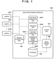
- the system according to the present embodiment includes N (N is an integer of 2 or more) cameras 1011, 1012, ..., 101N, and an image processing apparatus 100.
- the cameras 1011, 1012, ..., 101N and the image processing apparatus 100 are connected via a network such as a LAN or the Internet, and are configured to be able to perform data communication with one another.
- the network may be a wireless network or a wired network, or may be a combination of a wireless network and a wired network.
- the cameras 1011, 1012, ..., 101N are installed at locations different from one another, and capture still images or moving images in a set or controlled orientation.
- the installation layout of the cameras 1011, 1012, ..., 101N is not limited to any specific installation layout.
- some of the cameras may be collectively installed in the same area, for example, such that some of the cameras 1011, 1012, ..., 101N are installed in a room A, and others are installed in a room B.
- a captured image captured by each of the cameras 1011, 1012, ..., 101N is input into the image processing apparatus 100.
- each of the cameras 1011, 1012, ..., 101N serves to capture a still image
- the captured image is the still image itself. If each of the cameras 1011, 1012, ..., 101N serves to capture a moving image, the captured image is an image of each of the frames constituting the moving image.
- the image processing apparatus 100 has the function of generating various types of information for enabling image search using a color name as a query, based on the captured image acquired from each of the cameras 1011, 1012, ..., 101N. Further, the image processing apparatus 100 has the function of clipping and registering an image of an object serving as a search target from the captured image acquired by each of the cameras 1011, 1012, ..., 101N. Further, the image processing apparatus 100 has the function of performing an image search process for searching for, from among registered object images, the desired image, based on a color name that has been input as a query, and outputting the result.
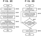
- each of the cameras 1011, 1012, ..., 101N first needs to be installed at a prescribed installation location. Then, after each of the cameras 1011, 1012, ..., 101N has been installed at the prescribed position, the image processing apparatus 100 divides the cameras 1011, 1012, ..., 101N into camera groups in each of which the cameras capture similar color information. The process performed by the image processing apparatus 100 for this division will be described in accordance with the flowchart shown in FIG. 2A .
- the cameras 1011, 1012, ..., 101N perform image capturing at a prescribed time interval in a prescribed time period, and output captured images. For example, each of the cameras 1011, 1012, ..., 101N performs image capturing every 5 minutes for 24 hours, and outputs captured images.
- an identifier generation unit 1041 acquires the captured images respectively output from the cameras 1011, 1012, ..., 101N. Then, the identifier generation unit 1041 creates, for each camera, an average RGB histogram of the RGB histograms of each of the captured image acquired from the camera. For example, in the case of creating an average RGB histogram of the RGB histograms of each of the captured images acquired from the camera 1011, the identifier generation unit 1041 performs the following process.
- the identifier generation unit 1041 Upon acquiring a captured image from the camera 1011, the identifier generation unit 1041 first creates, for all image regions of the captured image as a target, a histogram (RGB histogram) representing the appearance frequencies of the pixel values of the color components R, G, and B.
- the RGB histogram represents the number of appearances of the pixel value of the R component, the pixel value of the G component, and the pixel value of the B component within a range (e.g., 0 to 255) that the pixel values can take, and the number of bins is 16, for example.
- the identifier generation unit 1041 creates such an RGB histogram for each of the acquired captured images.
- the identifier generation unit 1041 uses the RGB histograms to create a histogram representing the average of the appearance frequencies of the pixel values of each of the color components R, G, and B during the prescribed time period.
- the thus created histogram is an average RGB histogram for the camera 1011.
- the average RGB histogram is created for each of the cameras 1011, 1012, ..., 101N.
- the identifier generation unit 1041 determines whether an average RGB histogram has been created for each of the cameras 1011, 1012, ..., 101N. If it is determined, as a result of this determination, that an average RGB histogram has been created for each of the cameras 1011, 1012, ..., 101N, the process proceeds to step S203. On the other hand, if, among the cameras 1011, 1012, ..., 101N, there is any camera left for which an average RGB histogram has not been created, the process returns to step S201, at which an average RGB histogram is created for the camera for which an average RGB histogram has not yet been created.
- average RGB histogram is an example of statistical information of each of the RGB histograms, and the statistical information of each of the RGB histograms is not limited to an average RGB histogram.
- the identifier generation unit 1041 divides the cameras 1011, 1012, ..., 101N into a plurality of groups, based on the average RGB histogram. Specifically, by using the average RGB histogram that has been created for each of the cameras 1011, 1012, ..., 101N, the identifier generation unit 1041 divides the cameras 1011, 1012, ..., 101N into camera groups in each of which the cameras have obtained similar average RGB histograms. For the method for the group division, it is possible to use various methods such as the mean shift method and the K-means method.
- each of the cameras 1011, 1012, ..., 101N outputs not only captured images, but also identification information (camera ID) unique to the camera.
- the identifier generation unit 1041 issues, for each of the divided groups, identification information (group ID) unique to the group, and manages the group ID and camera IDs of the cameras belonging to the group ID in association with each other.
- one unselected group is selected as a selected group from among the above-described plurality of groups.
- one camera is selected as a selected camera (selected image capturing device) from among one or more cameras belonging to the selected group. These selections may be performed by the user operating an operation unit (not shown).
- a creation unit 1042 may select a group in a predetermined order, and select, from among the cameras belonging to the selected group, a camera whose position in the order based on the camera ID is a predetermined position as the selected camera.
- the method for selecting the selected camera for example, when the number of camera belonging to the selected group is one, the one camera is selected as the selected camera.
- the user may select, from among the plurality of cameras, a camera installed at a location where the image of a sheet, which will be described later, can be easily captured.
- the user may select a camera installed at a location where variations of a lighting environment, which will be described later, can be easily reflected.
- the creation unit 1042 operates the selected camera to capture an image of a sheet on which a color chart is printed, and acquires the captured image of the sheet that has been captured by the selected camera.
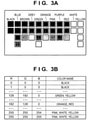
- FIG. 3A shows an example of the sheet whose image is captured by the selected camera. Patches of colors whose spectral reflectance distributions are known are disposed on the sheet, and the patches disposed on the same column correspond to the same color name. For example, the patches in the left end column differ, for example, in lightness and/or saturation, but are all associated with the color name "black", and therefore, the character string "black" is printed directly above the left-end patch column. Note that the printing position of the character string representing the color name is not limited to a position directly above the patch column.
- Another object may be used in place of the character string. In that case, it is necessary that the relationship between the object and the color name is known.
- FIG. 3A it is assumed that the color names are classified into 11 colors (black, blue, brown, grey, green, orange, pink, purple, red, white, and yellow) as described in the following document.
- color names are not limited to these, and it is also possible to use system color names prescribed in JIS, commonly used color names, or the like.
- the creation unit 1042 performs an image recognition process on the captured image, to specify a region of a patch in the sheet that is shown in the captured image, and a region of a character string (or may be an object other than a character string) representing a color name.
- the distortion is corrected by projective transformation. Note that the position of the region in which the character string representing a color name is printed on the sheet and the position of the region in which the patch corresponding to the color name is printed are registered in advance in the image processing apparatus 100 as known information.
- the creation unit 1042 specifies, based on the region of the sheet, a region (character string region) of a character string representing a color name and a region of a patch (patch region) by using the above-described known information.
- the creation unit 1042 recognizes, by a recognition process performed on the specified character string region, the character string representing the color name from the character string region, and extracts the color (RGB value) in the specified patch region, or in other words, the color of the patch on the captured image. Then, the creation unit 1042 registers the recognized character string representing the color name in association with each of the colors of the patches arranged directly below the character string.
- the recognized character string is registered in a table (color name table) as shown in FIG. 3B .
- B 0 to 255 is registered in advance in the third column from the left end.
- color name table By using such a color name table, "patch color name" shown as a character string on the sheet and the color of the patch on the captured image can be managed in association with each other.
- the configuration of the color name table is not limited to the configuration shown in FIG. 3B as long as the same purpose can be attained.
- the color name table is created with thinned RGB values, for example, when R, G, B are registered as 0, 15, 31, ..., 255 in the color name table, the row corresponding to the RGB value of a patch extracted from the captured image may not exist.
- the RGB value located at the closest distance to the RGB value of the patch on the color space may be specified, and the character string (character string of the color name) recognized from the character string region in the same column as the patch may be registered at the right end of the row of the specified RGB value.
- a plurality of color names can be registered at the right end column of the color name table. That is, a plurality of color names can be registered for the same RGB value.
- step S208 if image capturing has been completed under all of preset image-capturing environments, the process proceeds to step S208 via step S207. On the other hand, if there is any image-capturing environment left for which image capturing has not been completed, the process returns to step S205 in order to perform image capturing under that image-capturing environment.
- image capturing of the sheet is performed under image-capturing environments that are different from one another.
- image capturing may be performed on the sheet at a prescribed time interval in a prescribed time period, or the selected camera may perform image capturing on the sheet each time the user inputs an image capturing instruction by operating an operation unit (not shown).
- captured images obtained by performing image capturing on the sheet under image-capturing environments that are different from one another are output from the selected camera, and the creation unit 1042 creates a color name table, based on the captured images.
- a change in the lighting environment refers to a change caused by ON/OFF of lighting, the replacement of a lighting device, or the like in the case of image capturing performed in a room or building without a window, and a change with weather or time, or the like in the case of image capturing performed in a room or building with a window, or outdoor.
- steps S205 and S206 do not need to be performed each time image capturing is performed, and the processes of steps S205 and S206 may be performed if the change in the RGB histogram of the captured image is greater than or equal to a threshold value.
- the creation unit 1042 searches for an RGB value for which the character string of the corresponding color name is not registered in the color name table, as an unassociated RGB value. Then, the creation unit 1042 specifies an RGB value (only those RGB values for which the corresponding color names are registered) located at the closest Euclidean distance on the RGB space to the unassociated RGB value. Then the creation unit 1042 registers the character string of the color name registered in association with the specified RGB value as the character string representing the color name corresponding to the unassociated RGB value in the color name table. By such a color name table correction process, character strings representing color names can be registered in association with all the RGB values registered in the color name table.
- the creation unit 1042 registers the color name table created by the above-described process in association with the group ID (which may also be the camera ID of the selected camera) of the selected group.
- the color name table is created for each group, and therefore, it is possible to reduce time and labor as compared with the case where the color name table is created for each camera. It is, of course, possible to create two or more color name tables for one group.
- a region of a person (person region) is extracted from the captured image, then a region of upper garments and a region of lower garments are extracted from the person region, and the color of the upper garment region and the color of the lower garment region are recognized, and converted into color names. Then, the color name of the upper garment region and the color name of the lower garment region that have been converted are registered in a database 105 in association with an image in the person region, as metadata for the image in the person region.
- Such a registration process will be described with reference to the flowchart shown in FIG. 2C .
- a region extraction unit 103 acquires a captured image from each of the cameras 1011, 1012, ..., 101N.
- a series of processes from steps S211 to S214 is performed for the captured image acquired from each of the cameras 1011, 1012, ..., 101N.
- the region extraction unit 103 extracts a person region from the acquired captured image.
- the method for extracting a person region from an image is not limited to any specific method, and various methods are available. For example, a method is available in which the face of a person is detected from an image, and a person region is extracted by estimation from the position of the detected face. For face detection, the method described in the following document is available.
- the efficiency of the process can be increased by limiting the face detection range to a range greater than or equal to a predetermined size.
- the height of the rectangular shape of the face is multiplied by a constant, and the resultant is used as the person region.
- a feature extraction unit 1043 extracts the upper garment region and the lower garment region from the person region, and determines the average pixel value of each of the RGB components in the upper garment region and the average pixel value of each of the RGB components in the lower garment region. More specifically, first, the face region is removed from the person region, and the remaining region is equally divided into upper and lower regions. Then, the average pixel value of each of RGB of the pixels belonging to a region included in a circle region having a predetermined radius from the center point of one of the equally divided two regions is determined. For the other of the equally divided two regions as well, the average pixel value of each of RGB components is determined in the same manner.
- a color name conversion unit 1044 specifies a color name corresponding to the average pixel value of each of the RGB components of the upper garment region and the color name corresponding to the average pixel value of each of the RGB components of the lower garment region by referring to the above-described color name table.
- the color name table referred to at this time is a color name table registered in association with the group ID of the group (the group of the group ID associated with the camera ID of the camera) to which the camera that has performed image capturing on the captured image from which the upper garment region and the lower garment region are extracted.
- the color name (if two or more color names are registered, the two or more color names) registered at the right end of the row on which (r, g, b) is registered in the color name table is specified. Note that if the RGB value matching with the average pixel values is not found in the color name table, the RGB value (included in the color name table) having the smallest Euclidean distance to the average pixel values on the color space is specified, and the color name registered at the right end of the row of the specified RGB value is specified.
- the color name conversion unit 1044 registers the image (person image) in the person region extracted at step S211 and the color name of the upper garment region and the color name of the lower garment region (metadata) that have been specified at step S213 in the database 105 in association with each other.
- the metadata may further contain additional information, in addition to the color name of the upper garment region and the color name of the lower garment region.
- the camera ID of the camera that has performed image capturing on the captured image from which the person region has been extracted the image capturing date and time of the captured image, the installation location of the camera, and the like may be used as the additional information.
- an image search unit 106 acquires, at step S215, the color name of the upper garments and the color name of the lower garments that have been input, as the query. Note that in the case of using the sheet shown in FIG. 3A as the above-described sheet, any of the color names of the 11 colors included in the sheet are only registered in the color name table, and therefore, the color name that is input by the user is also any of the color names of the 11 colors.
- the color name of the upper garments or the color name of the lower garments is not limited to one, and a plurality of color names may be input.
- the user may input information for defining a search range.
- information for defining a search range examples include the camera ID, the installation location of the camera, and the image capturing date and time (or the range of the image capturing date and time).
- the image search unit 106 acquires the input information as well.
- the image search unit 106 searches the database 105 for the metadata that matches the information acquired at step S215 by the image search unit 106, and specifies the person image that is registered in the database 105 in association with the searched metadata.
- the image search unit 106 searches for the metadata containing the input image capturing date and time or the image capturing date and time within the input range of image capturing date and time, from among pieces of the metadata that match the query. Then, the image search unit 106 specifies the person image that is registered in the database 105 in association with the thus searched metadata.
- the image search unit 106 determines whether the image search of step S216 has been performed for all of the person images registered in the database 105.
- all of the person images registered in the database 105" refers to person images generated from the captured images captured by the cameras 1011, 1012, ..., 101N between the present time and the time prior to the current time by a predetermined time.
- which set of the person images registered in the database 105 is to be used as a search target is not limited to any specific case.
- the order of the search targets may be set such that the person image generated from the captured image captured by the camera 1011 is used first as the search target, and the person image generated from the captured image captured by the camera 1012 is subsequently used as the search target.
- step S216 if the image search of step S216 has been performed for all of the person images registered in the database 105, the process proceeds to step S218. On the other hand, if, among all of the person images registered in the database 105, there is any person image left for which the image search of step S216 has not yet been performed, the process returns to step S216 in order to use the person image as the search target.
- the output unit 107 outputs a result of the search performed by the image search unit 106.
- the output destination and the output form of the search result are not limited to any specific output destination or any specific output form.
- the search result may be output to a display device that is directly or indirectly connected to the image processing apparatus 100, or may be transmitted to an external apparatus via a network.
- the person images that have been sorted in accordance with, for example, the image capturing date and time may be displayed. Not only the person image, but also other information such as the image capturing date and time may be added to the displayed information.
- the present embodiment describes the image search process, taking, as an example, a case where the color name of the upper garments and the color name of the lower garments are input as a query
- the content that is input as a query is not limited to the color name of the upper garments and the color name of the lower garments. That is, the content that is input as a query may be the color name of another target object such as the hat worn by a person or a thing carried by a person.
- an image of the target object and the color name derived from the RGB value of the target object contained in the image by using a color name table need to be registered in the database 105 in association with each other (other information may be associated therewith as needed).
- the sheet shown in FIG. 3A or in other words, the sheet on which color names and patches of the colors associated with the color names are printed is used.
- the configuration of the sheet is not limited to the configuration shown in FIG. 3A as long as color names and colors can be extracted from an image of the sheet.
- the RGB value can be registered in association with the color name corresponding to the position of the region. It is also possible to use a sheet on which a character object in which the character representing the color name of a patch is filled with the color of the patch is printed. In the case of using such a sheet, the character represented by the character object and the color thereof are recognized, and the recognized character is registered as the color name corresponding to the recognized color.
- the present embodiment uses RGB as the color components, it is possible to use other color components such as YCC.
- the present embodiment uses color names as the categories for color classification, it is possible to use any other information as long as colors can be classified. For example, it is possible to use the notation of the Munsell color system, or may arbitrarily classify colors in accordance with the application and manage the colors by respectively assigning symbols thereto.
- the categories for color classification may be presented to the user as characters or images, or the representative color (e.g., the centroid of the categories on the RGB color space) of the relevant categories may be presented in a color chart.
- RGB values and color names are associated
- functions for associating RGB values with color names may be defined, or a dictionary associating RGB values with color names may be created by using machine learning.
- a display screen on which the color names and colors of patches are displayed may be used in place of the sheet on which the color names and colors of patches are printed.
- an image of the display screen, in place of the sheet is captured. That is, as long as a captured image containing the color name and color of a patch can be obtained, the method for presenting the color name and color of a patch to the camera is not limited to any specific method.
- FIG. 4 An exemplary configuration of a system according to the present embodiment will be described with reference to the block diagram shown in FIG. 4 .
- functional units that are the same as the functional units shown in FIG. 1 are denoted by the same reference numerals, and the description of the functional units has been omitted.
- an image processing apparatus 400 divides the cameras 1011, 1012, ..., 101N into camera groups in each of which the cameras capture similar color information.
- the cameras 1011, 1012, ..., 101N perform image capturing at a prescribed time interval in a prescribed time period, and output captured images.
- each of the cameras 1011, 1012, ..., 101N performs image capturing only once.
- the identifier generation unit 1041 creates an RGB histogram of the captured image captured by each of the cameras, and divides the cameras 1011, 1012, ..., 101N into a plurality of groups, based on the RGB histogram of the captured image of each of the cameras.
- the method for this group division is the same as that of the first embodiment except that the RGB histogram of each of the cameras is used in the present embodiment, whereas the average RGB histogram of each of the cameras is used in the first embodiment.
- the identifier generation unit 1041 issues an group ID for each of the divided groups, and manages the group ID and the camera IDs of the cameras belonging to the group having the group ID in association with each other.
- a color name table is created for each group in the same manner as in the first embodiment. Further, in the present embodiment, the color name table created for a group of interest is duplicated for each of the cameras belonging to the group of interest, and the camera ID of the camera and one of the duplicated color name tables are registered in a color name table database 410 in association with each other. Accordingly, in the color name table database 410, the color name table is registered in association with the camera ID of each camera, and the camera IDs of the cameras belonging to the same group are associated with the color name table created for that group.
- steps S510 to S512 are the same as steps S210 to S212 in FIG. 2C , and therefore, the description of these steps has been omitted.
- the region extraction unit 103 registers a person image, the camera ID of the camera that has captured the captured image from which the person image has been extracted, and the average pixel value of each of the RGB components in a region of upper garments and a region of lower garments in a database 405 in association with one another.
- a color e.g., the centroid of the RGB value corresponding to the color name on the RGB color space
- various color names here, the above-described 11 colors
- a list of patches of the representative colors respectively corresponding to the above-described 11 colors is displayed on the display screen.
- the user designates a color of the upper garments and a color of the lower garments from among the colors displayed in the list, and the method for color designation is not limited to any specific designation method.
- the user may touch the display position of the desired color by using his or her own finger or a pointer, or may move a cursor to the display position by using a user interface such as a mouse, and input a determination instruction at that position.
- a user interface such as a mouse
- an image search unit 406 acquires the color names corresponding to the designated positions. Accordingly, the color names corresponding to the upper garments color and the lower garments color designated by the user can be acquired as a query.
- the image search unit 406 performs the following process for each of the person images registered in the database 405.
- the image search unit 406 acquires the color name table corresponding to the camera ID associated with the person image from the color name table database 410.
- the image search unit 406 acquires the color name corresponding to "the average pixel value of each of the RGB components in each of the region of the upper garments and the region of the lower garments" associated with the person image in the acquired color name table. Accordingly, the color name of the upper garments and the color name of the lower garments in the person image can be acquired.
- the image search unit 406 performs the same image search process as that of step S216 described above by using the color name acquired at step S514, and the color name of the upper garments and the color name of the lower garments in each of the person images acquired at step S515.
- the image search unit 406 determines whether the image search of step S516 has been performed for all of the person images registered in the database 405, as with step S217 described above. Then, if the image search of step S516 has been performed for all of the person images registered in the database 405, the process proceeds to step S518. On the other hand, if, among all of the person images registered in the database 405, there is any person image left for which the image search of step S516 has not yet been performed, the process returns to step S516 in order to use the person image as a search target. At step S518, the output unit 107 outputs a result of the search performed by the image search unit 406, as with step S218 described above.
- the present embodiment provides a configuration for modifying the upper garments color name and/or the lower garments color name into the desired color name in the color name table used at the time of converting the average pixel value corresponding to the person image into a color name.
- Such a configuration is also effective, for example, when the user has not found a hit in a search result when performing a search by inputting a color in order to search for a desired image, but has found the desired image when performing a search by inputting another color.
- the user can designate the non-conforming image.
- the method for designating the non-conforming image is not limited to any specific designation method, and it is possible to use, for example, the same designation method as that used for the above-described color designation. If the non-conforming image has been designated by a user operation, the process proceeds to step S520 via step S519. If the non-conforming image is not designated by a user operation, the process ends via step S519.
- the user designates a desired color name as the color name having the average pixel value in the upper garment region and/or a desired color name as the color name having the average pixel value of the lower garment region that are associated with the non-conforming image. That is, if the user determines that the color of the upper garments does not match the input query, the user designates the desired color name as the color name having the average pixel value in the region of the upper garments. If the user determines that the color of the lower garments does not match the input query, the user designates the desired color name as the color name having the average pixel value in the region of the lower garments.
- the method for designating the color name used at this time is not limited to any specific designation method, and it is possible to use, for example, the same designation method as that used for the above-described color designation.
- the color name is designated from the above-described 11 colors.
- the color name may be designated by displaying 11 colors and the color names of the 11 colors on a display screen.
- the color defined by the average pixel value corresponding to the non-conforming image may be displayed on a display screen. This allows the user to designate the desired color name, while checking the average pixel value associated with the non-conforming image.
- the history of the color names that the user has recently searched for may be displayed so as to assist input of the color name. If there is no input of the color name, the changing of the color name is not performed.
- an input unit 408 acquires the color name (the upper garments color name and/or the lower garments color name) designated by the user.
- the input unit 408 acquires the camera ID and the average pixel value that are associated with the non-conforming image.
- a modification unit 409 acquires the color name table that is registered in the color name table database 410 in association with the camera ID acquired at step S521. Then, the modification unit 409 registers, in the acquired color name table, the color name acquired at step S520 as the color name corresponding to the average pixel value acquired at step S521.
- the modification unit 409 registers, in the acquired color name table, the color name acquired at step S520 as the color name corresponding to the average pixel value of the region of the upper garments that has been acquired at step S521. It is also assumed that as a result of the user determining that the color of the lower garments does not match the input query, the desired color name is designated as the color name having the average pixel value in the region of the lower garments. At this time, the modification unit 409 registers, in the acquired color name table, the color name acquired at step S520 as the color name corresponding to the average pixel value in the region of the lower garments that has been acquired at step S521.
- the RGB value located at the closest distance to the aforementioned average pixel value on the color space is specified, and the color name acquired at step S520 is registered as the color name corresponding to the specified RGB value.
- the color name that has already been registered as the color name corresponding to the average pixel value acquired at step S521 is updated to the color name acquired at step S520.
- the acquisition of the RGB histogram during installation of cameras is performed only once, and thereby, the time and labor of grouping the cameras during installation of the cameras can be reduced.
- the color name table can be modified for each camera, and therefore, it is possible to create a color name table that is customized for each camera, thus preventing a reduction in the search accuracy and enhancing the search accuracy.
- the group to which the camera belongs may also be modified in the same manner.
- the camera ID corresponding to the non-conforming image is "A”.
- the configuration up to the modification process for the color name table may be performed in the same manner as in the first embodiment. That is, the configuration of the modification process for the color name table in the second embodiment may be added to the configuration of the first embodiment (in that case, the modification process for the color name table needs to be modified as appropriate in conformity with the first embodiment).
- the functional units described as being included in the image processing apparatus in FIGS. 1 and 4 may not be necessarily placed in one image processing apparatus, and may be distributed over two or more apparatuses.
- the identifier generation unit 1041, the creation unit 1042, the feature extraction unit 1043, and the color name conversion unit 1044 may be implemented by one apparatus, and the region extraction unit 103, the database 105, the image search unit 106, and the output unit 107 may be implemented by two or more apparatuses.
- FIG. 1 the identifier generation unit 1041, the creation unit 1042, the feature extraction unit 1043, and the color name conversion unit 1044 may be implemented by one apparatus, and the region extraction unit 103, the database 105, the image search unit 106, and the output unit 107 may be implemented by two or more apparatuses.
- the identifier generation unit 1041, the creation unit 1042, the feature extraction unit 1043, the color name conversion unit 1044, the modification unit 409, and the input unit 408 may be implemented by one apparatus, and the remaining functional units may be implemented by two or more apparatuses.
- each of the image processing apparatuses 100 and 400 is described as an example of an image processing apparatus having the following configuration, and it is possible to use any configuration as long as it results in the following configuration. That is, a captured image obtained by capturing an image of a surface on which a color chart is disposed such that color information representing a color included in the color chart can be derived is acquired, the color information is derived from the captured image, and the color of the color chart that is contained in the captured image is extracted. Then, the derived color information and the extracted color are registered in association with each other.
- the image processing apparatus is not limited to a configuration in which a captured image is directly acquired from a camera, and it is possible to adopt a configuration in which a captured image that has been output from a camera is stored in a storage device, and the image processing apparatus acquires the captured image by reading it out from the storage device.
- the functional units shown in FIGS. 1 and 4 may be configured with hardware, but may be partly configured with software.
- the region extraction unit 103, the identifier generation unit 1041, the creation unit 1042, the feature extraction unit 1043, the color name conversion unit 1044, the image search unit 106, and the output unit 107 may be configured with software.
- the region extraction unit 103, the identifier generation unit 1041, the creation unit 1042, the feature extraction unit 1043, the color name conversion unit 1044, the modification unit 409, the input unit 408, the image search unit 406, and the output unit 107 may be configured with software.
- any computer apparatus capable of executing such software is applicable to the image processing apparatus 100/400.
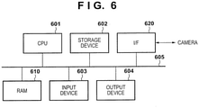
- An exemplary hardware configuration of a computer apparatus applicable to the image processing apparatus 100/400 will be described with reference to the block diagram shown in FIG. 6 . Note that the hardware configuration shown in FIG. 6 is merely an example of the hardware configuration of the computer apparatus applicable to the image processing apparatus 100/400.
- a CPU 601 By executing processes by using a computer program and data that are stored in a RAM 610, a CPU 601 performs overall operation control of the computer apparatus and executes or controls the processes described above as being executed by the image processing apparatus 100/400.
- the RAM 610 has an area for storing a computer program and data that are loaded from a storage device 602. Further, the RAM 610 has an area for storing captured images and camera IDs received from the cameras 1011, 1012, ..., 101N via an I/F (interface) 620. Further, the RAM 610 has a work area used by the CPU 601 to execute or control various processes. In this manner, the RAM 610 can provide various areas as needed.
- the storage device 602 is a mass information storage device typified by a hard disk drive device.
- An OS operating system
- the computer program includes a computer program for causing the CPU 601 to implement the functions of the region extraction unit 103, the identifier generation unit 1041, the creation unit 1042, the feature extraction unit 1043, the color name conversion unit 1044, the image search unit 106, and the output unit 107.
- the computer program includes a computer program for causing the CPU 601 to implement the functions of the region extraction unit 103, the identifier generation unit 1041, the creation unit 1042, the feature extraction unit 1043, the color name conversion unit 1044, the modification unit 409, the input unit 408, the image search unit 406, and the output unit 107.
- the data saved in the storage device 602 includes the information described as the known information in the above description and the information described as a management target (registration target) in the above description.
- the database 105, the database 405, and the color name table database 410 that are described above are created in the storage device 602.
- the computer program and data saved in the storage device 602 are loaded as needed onto the RAM 610 in accordance with control by the CPU 601, and are used as processing targets of the CPU 601.
- the above-described cameras 1011, 1012, ..., 101N are connected to the I/F 620, and the computer apparatus of the present embodiment performs data communication between the cameras 1011, 1012, ..., 101N via the I/F 620.
- An input device 603 is configured with user interfaces such as a mouse and a keyboard, and allows various instructions to be input into the CPU 601 by being operated by the user. For example, each of the user operations in the above description can be implemented by the user operating the input device 603.
- An output device 604 is configured with a CRT, a liquid crystal screen or the like, and can display the result of processing executed by the CPU 601 by using images, characters and the like.
- the output device 604 can display GUIs (graphical user interfaces) for the above-described various user operations, search results and the like.
- the input device 603 and the output device 604 may be integrated with each other to form a touch panel screen. All of the CPU 601, the RAM 610, the storage device 602, the I/F 620, the input device 603, and the output device 604 are connected to a bus 605.
- Embodiment(s) of the present invention can also be realized by a computer of a system or apparatus that reads out and executes computer executable instructions (e.g., one or more programs) recorded on a storage medium (which may also be referred to more fully as a 'non-transitory computer-readable storage medium') to perform the functions of one or more of the above-described embodiment(s) and/or that includes one or more circuits (e.g., application specific integrated circuit (ASIC)) for performing the functions of one or more of the above-described embodiment(s), and by a method performed by the computer of the system or apparatus by, for example, reading out and executing the computer executable instructions from the storage medium to perform the functions of one or more of the above-described embodiment(s) and/or controlling the one or more circuits to perform the functions of one or more of the above-described embodiment(s).
- computer executable instructions e.g., one or more programs
- a storage medium which may also be referred to more fully as
- the computer may comprise one or more processors (e.g., central processing unit (CPU), micro processing unit (MPU)) and may include a network of separate computers or separate processors to read out and execute the computer executable instructions.
- the computer executable instructions may be provided to the computer, for example, from a network or the storage medium.
- the storage medium may include, for example, one or more of a hard disk, a random-access memory (RAM), a read only memory (ROM), a storage of distributed computing systems, an optical disk (such as a compact disc (CD), digital versatile disc (DVD), or Blu-ray Disc (BD) TM ), a flash memory device, a memory card, and the like.
Landscapes
- Engineering & Computer Science (AREA)
- Theoretical Computer Science (AREA)
- General Physics & Mathematics (AREA)
- Physics & Mathematics (AREA)
- Library & Information Science (AREA)
- Computer Vision & Pattern Recognition (AREA)
- Data Mining & Analysis (AREA)
- Databases & Information Systems (AREA)
- General Engineering & Computer Science (AREA)
- Multimedia (AREA)
- Signal Processing (AREA)
- Image Processing (AREA)
- Image Analysis (AREA)
- Information Retrieval, Db Structures And Fs Structures Therefor (AREA)
- Spectrometry And Color Measurement (AREA)
Applications Claiming Priority (1)
| Application Number | Priority Date | Filing Date | Title |
|---|---|---|---|
| JP2016097386A JP6525921B2 (ja) | 2016-05-13 | 2016-05-13 | 画像処理装置、画像処理方法、検索装置 |
Publications (3)
| Publication Number | Publication Date |
|---|---|
| EP3244323A1 EP3244323A1 (en) | 2017-11-15 |
| EP3244323A8 EP3244323A8 (en) | 2018-01-03 |
| EP3244323B1 true EP3244323B1 (en) | 2022-03-23 |
Family
ID=58671323
Family Applications (1)
| Application Number | Title | Priority Date | Filing Date |
|---|---|---|---|
| EP17000734.8A Not-in-force EP3244323B1 (en) | 2016-05-13 | 2017-04-27 | Image processing apparatus, image processing method, search apparatus, and computer program |
Country Status (4)
| Country | Link |
|---|---|
| US (1) | US10430457B2 (enExample) |
| EP (1) | EP3244323B1 (enExample) |
| JP (1) | JP6525921B2 (enExample) |
| CN (1) | CN107368838B (enExample) |
Families Citing this family (8)
| Publication number | Priority date | Publication date | Assignee | Title |
|---|---|---|---|---|
| US11057573B2 (en) * | 2017-12-20 | 2021-07-06 | Texas Instruments Incorporated | Multi camera image processing |
| JP7011472B2 (ja) * | 2018-01-15 | 2022-01-26 | キヤノン株式会社 | 情報処理装置、情報処理方法 |
| JP7195782B2 (ja) * | 2018-06-27 | 2022-12-26 | キヤノン株式会社 | 情報処理装置、制御方法及びプログラム |
| JP7041601B2 (ja) * | 2018-09-05 | 2022-03-24 | シャープ株式会社 | 情報処理装置、情報処理装置における表示方法及びプログラム |
| JP7361551B2 (ja) | 2019-09-20 | 2023-10-16 | キヤノン株式会社 | デバイス、制御方法、及びプログラム |
| JP2021047827A (ja) | 2019-09-20 | 2021-03-25 | キヤノン株式会社 | デバイス、システム、制御方法、及びプログラム |
| CN111833340B (zh) | 2020-07-21 | 2024-03-26 | 阿波罗智能技术(北京)有限公司 | 图像检测方法、装置、电子设备及存储介质 |
| CN116127118A (zh) * | 2022-12-21 | 2023-05-16 | 微梦创科网络科技(中国)有限公司 | 一种相似图像检索的方法、装置、电子设备及存储介质 |
Family Cites Families (14)
| Publication number | Priority date | Publication date | Assignee | Title |
|---|---|---|---|---|
| US5311293A (en) * | 1983-07-18 | 1994-05-10 | Chromatics Color Sciences International, Inc. | Method and instrument for selecting personal compatible colors |
| US6081276A (en) * | 1996-11-14 | 2000-06-27 | International Business Machines Corporation | Method and apparatus for creating a color name dictionary and for querying an image by color name |
| JP4532682B2 (ja) * | 2000-06-29 | 2010-08-25 | 株式会社日本総合研究所 | 異なる光源下におけるカラー画像データの変換方法,装置およびカラー画像データ変換のためのプログラムを記録した媒体 |
| WO2004027695A1 (en) * | 2002-09-20 | 2004-04-01 | International Business Machines Coporation | Color naming, color categorization and describing color composition of images |
| JP4708192B2 (ja) * | 2006-01-10 | 2011-06-22 | パナソニック株式会社 | 動的なカメラ色補正装置およびそれを用いた映像検索装置 |
| US8018494B2 (en) * | 2006-01-10 | 2011-09-13 | Panasonic Corporation | Color correction device, color correction method, dynamic camera color correction device, and video search device using the same |
| JP2008225887A (ja) * | 2007-03-13 | 2008-09-25 | Toshiba Corp | 画像検索システム |
| JP2009271577A (ja) * | 2008-04-30 | 2009-11-19 | Panasonic Corp | 類似画像検索の結果表示装置及び類似画像検索の結果表示方法 |
| EP2549759B1 (en) * | 2011-07-19 | 2016-01-13 | Axis AB | Method and system for facilitating color balance synchronization between a plurality of video cameras as well as method and system for obtaining object tracking between two or more video cameras |
| JP5259893B1 (ja) * | 2011-08-05 | 2013-08-07 | 楽天株式会社 | 色決定装置、色決定システム、色決定方法、情報記録媒体、ならびに、プログラム |
| JP5845987B2 (ja) * | 2012-03-13 | 2016-01-20 | 株式会社リコー | 撮像装置、撮像システム、測色装置、測色システム及び画像形成装置 |
| EP4296963B1 (en) * | 2012-08-21 | 2025-01-15 | Adeia Imaging LLC | Method for depth detection in images captured using array cameras |
| US9773021B2 (en) * | 2013-01-30 | 2017-09-26 | Hewlett-Packard Development Company, L.P. | Corrected optical property value-based search query |
| JP6558435B2 (ja) * | 2015-03-26 | 2019-08-14 | コニカミノルタ株式会社 | 測色装置および測色方法 |
-
2016
- 2016-05-13 JP JP2016097386A patent/JP6525921B2/ja active Active
-
2017
- 2017-04-27 EP EP17000734.8A patent/EP3244323B1/en not_active Not-in-force
- 2017-05-03 US US15/585,695 patent/US10430457B2/en active Active
- 2017-05-08 CN CN201710316453.9A patent/CN107368838B/zh active Active
Also Published As
| Publication number | Publication date |
|---|---|
| US10430457B2 (en) | 2019-10-01 |
| JP6525921B2 (ja) | 2019-06-05 |
| JP2017204241A (ja) | 2017-11-16 |
| CN107368838B (zh) | 2021-03-16 |
| CN107368838A (zh) | 2017-11-21 |
| US20170329775A1 (en) | 2017-11-16 |
| EP3244323A8 (en) | 2018-01-03 |
| EP3244323A1 (en) | 2017-11-15 |
Similar Documents
| Publication | Publication Date | Title |
|---|---|---|
| EP3244323B1 (en) | Image processing apparatus, image processing method, search apparatus, and computer program | |
| US10672133B2 (en) | Moving object tracking device, display device, and moving object tracking method | |
| US10853407B2 (en) | Correlating image annotations with foreground features | |
| US10891740B2 (en) | Moving object tracking apparatus, moving object tracking method, and computer program product | |
| US10891019B2 (en) | Dynamic thumbnail selection for search results | |
| JP2004522228A (ja) | ディジタル画像を表現し比較する方法 | |
| JPWO2011045920A1 (ja) | 色彩解析装置、色彩解析方法、及び色彩解析プログラム | |
| JP2015187759A (ja) | 画像検索装置、画像検索方法 | |
| Zangana et al. | A new algorithm for human face detection using skin color tone | |
| KR20150107499A (ko) | 오브젝트 인식 장치 및 그 제어 방법 | |
| TW201933179A (zh) | 影像數據擷取方法及影像數據擷取裝置 | |
| US10055822B2 (en) | Image processing apparatus, image processing method, and non-transitory computer-readable storage medium | |
| US20180144074A1 (en) | Retrieving apparatus, display device, and retrieving method | |
| JP2013164832A (ja) | オブジェクト認識装置および方法 | |
| KR101160968B1 (ko) | 색상 정보 및 외곽선 정보를 이용한 문자열 인식 시스템 및 그 방법 | |
| CN108268881A (zh) | 电子设备、目标图像识别方法及装置 | |
| JP2017219984A (ja) | 画像検索システム、画像辞書生成システム、画像処理システム及びプログラム | |
| JP6419560B2 (ja) | 検索装置、方法及びプログラム | |
| JP2020017110A (ja) | オブジェクト検出システム | |
| US11244185B2 (en) | Image search device, image search system, and image search method | |
| CN112884740B (zh) | 一种图像检测方法、装置、电子设备及存储介质 | |
| JP6855175B2 (ja) | 画像処理装置、画像処理方法およびプログラム | |
| JP2007052466A (ja) | 画像処理方法、画像処理システム、および画像処理プログラム | |
| KR101465933B1 (ko) | 영상에서 컬러 객체를 검출하는 방법, 영상에서 컬러 객체를 검출하는 장치 및 영상에서 복수의 컬러 객체를 검출하는 방법 | |
| US20200372070A1 (en) | Search system, operation method of terminal apparatus, and program |
Legal Events
| Date | Code | Title | Description |
|---|---|---|---|
| PUAI | Public reference made under article 153(3) epc to a published international application that has entered the european phase |
Free format text: ORIGINAL CODE: 0009012 |
|
| STAA | Information on the status of an ep patent application or granted ep patent |
Free format text: STATUS: THE APPLICATION HAS BEEN PUBLISHED |
|
| AK | Designated contracting states |
Kind code of ref document: A1 Designated state(s): AL AT BE BG CH CY CZ DE DK EE ES FI FR GB GR HR HU IE IS IT LI LT LU LV MC MK MT NL NO PL PT RO RS SE SI SK SM TR |
|
| AX | Request for extension of the european patent |
Extension state: BA ME |
|
| STAA | Information on the status of an ep patent application or granted ep patent |
Free format text: STATUS: REQUEST FOR EXAMINATION WAS MADE |
|
| 17P | Request for examination filed |
Effective date: 20180515 |
|
| RBV | Designated contracting states (corrected) |
Designated state(s): AL AT BE BG CH CY CZ DE DK EE ES FI FR GB GR HR HU IE IS IT LI LT LU LV MC MK MT NL NO PL PT RO RS SE SI SK SM TR |
|
| STAA | Information on the status of an ep patent application or granted ep patent |
Free format text: STATUS: EXAMINATION IS IN PROGRESS |
|
| 17Q | First examination report despatched |
Effective date: 20190702 |
|
| R17C | First examination report despatched (corrected) |
Effective date: 20190704 |
|
| REG | Reference to a national code |
Ref country code: DE Ref legal event code: R079 Ref document number: 602017054838 Country of ref document: DE Free format text: PREVIOUS MAIN CLASS: G06F0017300000 Ipc: G06F0016583000 |
|
| RIC1 | Information provided on ipc code assigned before grant |
Ipc: G06F 16/583 20190101AFI20210910BHEP |
|
| GRAP | Despatch of communication of intention to grant a patent |
Free format text: ORIGINAL CODE: EPIDOSNIGR1 |
|
| STAA | Information on the status of an ep patent application or granted ep patent |
Free format text: STATUS: GRANT OF PATENT IS INTENDED |
|
| INTG | Intention to grant announced |
Effective date: 20211025 |
|
| GRAS | Grant fee paid |
Free format text: ORIGINAL CODE: EPIDOSNIGR3 |
|
| GRAA | (expected) grant |
Free format text: ORIGINAL CODE: 0009210 |
|
| STAA | Information on the status of an ep patent application or granted ep patent |
Free format text: STATUS: THE PATENT HAS BEEN GRANTED |
|
| AK | Designated contracting states |
Kind code of ref document: B1 Designated state(s): AL AT BE BG CH CY CZ DE DK EE ES FI FR GB GR HR HU IE IS IT LI LT LU LV MC MK MT NL NO PL PT RO RS SE SI SK SM TR |
|
| REG | Reference to a national code |
Ref country code: GB Ref legal event code: FG4D |
|
| REG | Reference to a national code |
Ref country code: CH Ref legal event code: EP |
|
| REG | Reference to a national code |
Ref country code: IE Ref legal event code: FG4D |
|
| REG | Reference to a national code |
Ref country code: DE Ref legal event code: R096 Ref document number: 602017054838 Country of ref document: DE |
|
| REG | Reference to a national code |
Ref country code: AT Ref legal event code: REF Ref document number: 1477943 Country of ref document: AT Kind code of ref document: T Effective date: 20220415 |
|
| REG | Reference to a national code |
Ref country code: LT Ref legal event code: MG9D |
|
| REG | Reference to a national code |
Ref country code: NL Ref legal event code: MP Effective date: 20220323 |
|
| PG25 | Lapsed in a contracting state [announced via postgrant information from national office to epo] |
Ref country code: SE Free format text: LAPSE BECAUSE OF FAILURE TO SUBMIT A TRANSLATION OF THE DESCRIPTION OR TO PAY THE FEE WITHIN THE PRESCRIBED TIME-LIMIT Effective date: 20220323 Ref country code: RS Free format text: LAPSE BECAUSE OF FAILURE TO SUBMIT A TRANSLATION OF THE DESCRIPTION OR TO PAY THE FEE WITHIN THE PRESCRIBED TIME-LIMIT Effective date: 20220323 Ref country code: NO Free format text: LAPSE BECAUSE OF FAILURE TO SUBMIT A TRANSLATION OF THE DESCRIPTION OR TO PAY THE FEE WITHIN THE PRESCRIBED TIME-LIMIT Effective date: 20220623 Ref country code: LT Free format text: LAPSE BECAUSE OF FAILURE TO SUBMIT A TRANSLATION OF THE DESCRIPTION OR TO PAY THE FEE WITHIN THE PRESCRIBED TIME-LIMIT Effective date: 20220323 Ref country code: HR Free format text: LAPSE BECAUSE OF FAILURE TO SUBMIT A TRANSLATION OF THE DESCRIPTION OR TO PAY THE FEE WITHIN THE PRESCRIBED TIME-LIMIT Effective date: 20220323 Ref country code: BG Free format text: LAPSE BECAUSE OF FAILURE TO SUBMIT A TRANSLATION OF THE DESCRIPTION OR TO PAY THE FEE WITHIN THE PRESCRIBED TIME-LIMIT Effective date: 20220623 |
|
| REG | Reference to a national code |
Ref country code: AT Ref legal event code: MK05 Ref document number: 1477943 Country of ref document: AT Kind code of ref document: T Effective date: 20220323 |
|
| PG25 | Lapsed in a contracting state [announced via postgrant information from national office to epo] |
Ref country code: LV Free format text: LAPSE BECAUSE OF FAILURE TO SUBMIT A TRANSLATION OF THE DESCRIPTION OR TO PAY THE FEE WITHIN THE PRESCRIBED TIME-LIMIT Effective date: 20220323 Ref country code: GR Free format text: LAPSE BECAUSE OF FAILURE TO SUBMIT A TRANSLATION OF THE DESCRIPTION OR TO PAY THE FEE WITHIN THE PRESCRIBED TIME-LIMIT Effective date: 20220624 Ref country code: FI Free format text: LAPSE BECAUSE OF FAILURE TO SUBMIT A TRANSLATION OF THE DESCRIPTION OR TO PAY THE FEE WITHIN THE PRESCRIBED TIME-LIMIT Effective date: 20220323 |
|
| PG25 | Lapsed in a contracting state [announced via postgrant information from national office to epo] |
Ref country code: NL Free format text: LAPSE BECAUSE OF FAILURE TO SUBMIT A TRANSLATION OF THE DESCRIPTION OR TO PAY THE FEE WITHIN THE PRESCRIBED TIME-LIMIT Effective date: 20220323 |
|
| PG25 | Lapsed in a contracting state [announced via postgrant information from national office to epo] |
Ref country code: SM Free format text: LAPSE BECAUSE OF FAILURE TO SUBMIT A TRANSLATION OF THE DESCRIPTION OR TO PAY THE FEE WITHIN THE PRESCRIBED TIME-LIMIT Effective date: 20220323 Ref country code: SK Free format text: LAPSE BECAUSE OF FAILURE TO SUBMIT A TRANSLATION OF THE DESCRIPTION OR TO PAY THE FEE WITHIN THE PRESCRIBED TIME-LIMIT Effective date: 20220323 Ref country code: RO Free format text: LAPSE BECAUSE OF FAILURE TO SUBMIT A TRANSLATION OF THE DESCRIPTION OR TO PAY THE FEE WITHIN THE PRESCRIBED TIME-LIMIT Effective date: 20220323 Ref country code: PT Free format text: LAPSE BECAUSE OF FAILURE TO SUBMIT A TRANSLATION OF THE DESCRIPTION OR TO PAY THE FEE WITHIN THE PRESCRIBED TIME-LIMIT Effective date: 20220725 Ref country code: ES Free format text: LAPSE BECAUSE OF FAILURE TO SUBMIT A TRANSLATION OF THE DESCRIPTION OR TO PAY THE FEE WITHIN THE PRESCRIBED TIME-LIMIT Effective date: 20220323 Ref country code: EE Free format text: LAPSE BECAUSE OF FAILURE TO SUBMIT A TRANSLATION OF THE DESCRIPTION OR TO PAY THE FEE WITHIN THE PRESCRIBED TIME-LIMIT Effective date: 20220323 Ref country code: CZ Free format text: LAPSE BECAUSE OF FAILURE TO SUBMIT A TRANSLATION OF THE DESCRIPTION OR TO PAY THE FEE WITHIN THE PRESCRIBED TIME-LIMIT Effective date: 20220323 Ref country code: AT Free format text: LAPSE BECAUSE OF FAILURE TO SUBMIT A TRANSLATION OF THE DESCRIPTION OR TO PAY THE FEE WITHIN THE PRESCRIBED TIME-LIMIT Effective date: 20220323 |
|
| REG | Reference to a national code |
Ref country code: DE Ref legal event code: R119 Ref document number: 602017054838 Country of ref document: DE |
|
| PG25 | Lapsed in a contracting state [announced via postgrant information from national office to epo] |
Ref country code: PL Free format text: LAPSE BECAUSE OF FAILURE TO SUBMIT A TRANSLATION OF THE DESCRIPTION OR TO PAY THE FEE WITHIN THE PRESCRIBED TIME-LIMIT Effective date: 20220323 Ref country code: IS Free format text: LAPSE BECAUSE OF FAILURE TO SUBMIT A TRANSLATION OF THE DESCRIPTION OR TO PAY THE FEE WITHIN THE PRESCRIBED TIME-LIMIT Effective date: 20220723 Ref country code: AL Free format text: LAPSE BECAUSE OF FAILURE TO SUBMIT A TRANSLATION OF THE DESCRIPTION OR TO PAY THE FEE WITHIN THE PRESCRIBED TIME-LIMIT Effective date: 20220323 |
|
| REG | Reference to a national code |
Ref country code: CH Ref legal event code: PL |
|
| REG | Reference to a national code |
Ref country code: BE Ref legal event code: MM Effective date: 20220430 |
|
| PLBE | No opposition filed within time limit |
Free format text: ORIGINAL CODE: 0009261 |
|
| STAA | Information on the status of an ep patent application or granted ep patent |
Free format text: STATUS: NO OPPOSITION FILED WITHIN TIME LIMIT |
|
| PG25 | Lapsed in a contracting state [announced via postgrant information from national office to epo] |
Ref country code: MC Free format text: LAPSE BECAUSE OF FAILURE TO SUBMIT A TRANSLATION OF THE DESCRIPTION OR TO PAY THE FEE WITHIN THE PRESCRIBED TIME-LIMIT Effective date: 20220323 Ref country code: LU Free format text: LAPSE BECAUSE OF NON-PAYMENT OF DUE FEES Effective date: 20220427 Ref country code: LI Free format text: LAPSE BECAUSE OF NON-PAYMENT OF DUE FEES Effective date: 20220430 Ref country code: DK Free format text: LAPSE BECAUSE OF FAILURE TO SUBMIT A TRANSLATION OF THE DESCRIPTION OR TO PAY THE FEE WITHIN THE PRESCRIBED TIME-LIMIT Effective date: 20220323 Ref country code: DE Free format text: LAPSE BECAUSE OF NON-PAYMENT OF DUE FEES Effective date: 20221103 Ref country code: CH Free format text: LAPSE BECAUSE OF NON-PAYMENT OF DUE FEES Effective date: 20220430 |
|
| PG25 | Lapsed in a contracting state [announced via postgrant information from national office to epo] |
Ref country code: BE Free format text: LAPSE BECAUSE OF NON-PAYMENT OF DUE FEES Effective date: 20220430 |
|
| 26N | No opposition filed |
Effective date: 20230102 |
|
| PG25 | Lapsed in a contracting state [announced via postgrant information from national office to epo] |
Ref country code: IE Free format text: LAPSE BECAUSE OF NON-PAYMENT OF DUE FEES Effective date: 20220427 Ref country code: FR Free format text: LAPSE BECAUSE OF NON-PAYMENT OF DUE FEES Effective date: 20220523 |
|
| PG25 | Lapsed in a contracting state [announced via postgrant information from national office to epo] |
Ref country code: SI Free format text: LAPSE BECAUSE OF FAILURE TO SUBMIT A TRANSLATION OF THE DESCRIPTION OR TO PAY THE FEE WITHIN THE PRESCRIBED TIME-LIMIT Effective date: 20220323 |
|
| PG25 | Lapsed in a contracting state [announced via postgrant information from national office to epo] |
Ref country code: IT Free format text: LAPSE BECAUSE OF FAILURE TO SUBMIT A TRANSLATION OF THE DESCRIPTION OR TO PAY THE FEE WITHIN THE PRESCRIBED TIME-LIMIT Effective date: 20220323 |
|
| PG25 | Lapsed in a contracting state [announced via postgrant information from national office to epo] |
Ref country code: HU Free format text: LAPSE BECAUSE OF FAILURE TO SUBMIT A TRANSLATION OF THE DESCRIPTION OR TO PAY THE FEE WITHIN THE PRESCRIBED TIME-LIMIT; INVALID AB INITIO Effective date: 20170427 |
|
| PG25 | Lapsed in a contracting state [announced via postgrant information from national office to epo] |
Ref country code: MK Free format text: LAPSE BECAUSE OF FAILURE TO SUBMIT A TRANSLATION OF THE DESCRIPTION OR TO PAY THE FEE WITHIN THE PRESCRIBED TIME-LIMIT Effective date: 20220323 Ref country code: CY Free format text: LAPSE BECAUSE OF FAILURE TO SUBMIT A TRANSLATION OF THE DESCRIPTION OR TO PAY THE FEE WITHIN THE PRESCRIBED TIME-LIMIT Effective date: 20220323 |
|
| PGFP | Annual fee paid to national office [announced via postgrant information from national office to epo] |
Ref country code: GB Payment date: 20240320 Year of fee payment: 8 |
|
| PG25 | Lapsed in a contracting state [announced via postgrant information from national office to epo] |
Ref country code: TR Free format text: LAPSE BECAUSE OF FAILURE TO SUBMIT A TRANSLATION OF THE DESCRIPTION OR TO PAY THE FEE WITHIN THE PRESCRIBED TIME-LIMIT Effective date: 20220323 |
|
| PG25 | Lapsed in a contracting state [announced via postgrant information from national office to epo] |
Ref country code: MT Free format text: LAPSE BECAUSE OF FAILURE TO SUBMIT A TRANSLATION OF THE DESCRIPTION OR TO PAY THE FEE WITHIN THE PRESCRIBED TIME-LIMIT Effective date: 20220323 |
|
| GBPC | Gb: european patent ceased through non-payment of renewal fee |
Effective date: 20250427 |
|
| PG25 | Lapsed in a contracting state [announced via postgrant information from national office to epo] |
Ref country code: GB Free format text: LAPSE BECAUSE OF NON-PAYMENT OF DUE FEES Effective date: 20250427 |