EP3244283A1 - Adjustable portable device holder - Google Patents
Adjustable portable device holder Download PDFInfo
- Publication number
- EP3244283A1 EP3244283A1 EP17178044.8A EP17178044A EP3244283A1 EP 3244283 A1 EP3244283 A1 EP 3244283A1 EP 17178044 A EP17178044 A EP 17178044A EP 3244283 A1 EP3244283 A1 EP 3244283A1
- Authority
- EP
- European Patent Office
- Prior art keywords
- mounting
- adjustable
- clamping element
- portable device
- device holder
- Prior art date
- Legal status (The legal status is an assumption and is not a legal conclusion. Google has not performed a legal analysis and makes no representation as to the accuracy of the status listed.)
- Granted
Links
Images
Classifications
-
- F—MECHANICAL ENGINEERING; LIGHTING; HEATING; WEAPONS; BLASTING
- F16—ENGINEERING ELEMENTS AND UNITS; GENERAL MEASURES FOR PRODUCING AND MAINTAINING EFFECTIVE FUNCTIONING OF MACHINES OR INSTALLATIONS; THERMAL INSULATION IN GENERAL
- F16M—FRAMES, CASINGS OR BEDS OF ENGINES, MACHINES OR APPARATUS, NOT SPECIFIC TO ENGINES, MACHINES OR APPARATUS PROVIDED FOR ELSEWHERE; STANDS; SUPPORTS
- F16M11/00—Stands or trestles as supports for apparatus or articles placed thereon Stands for scientific apparatus such as gravitational force meters
- F16M11/02—Heads
- F16M11/04—Means for attachment of apparatus; Means allowing adjustment of the apparatus relatively to the stand
-
- H—ELECTRICITY
- H04—ELECTRIC COMMUNICATION TECHNIQUE
- H04M—TELEPHONIC COMMUNICATION
- H04M1/00—Substation equipment, e.g. for use by subscribers
- H04M1/02—Constructional features of telephone sets
- H04M1/04—Supports for telephone transmitters or receivers
-
- B—PERFORMING OPERATIONS; TRANSPORTING
- B60—VEHICLES IN GENERAL
- B60R—VEHICLES, VEHICLE FITTINGS, OR VEHICLE PARTS, NOT OTHERWISE PROVIDED FOR
- B60R11/00—Arrangements for holding or mounting articles, not otherwise provided for
- B60R11/02—Arrangements for holding or mounting articles, not otherwise provided for for radio sets, television sets, telephones, or the like; Arrangement of controls thereof
-
- B—PERFORMING OPERATIONS; TRANSPORTING
- B60—VEHICLES IN GENERAL
- B60R—VEHICLES, VEHICLE FITTINGS, OR VEHICLE PARTS, NOT OTHERWISE PROVIDED FOR
- B60R11/00—Arrangements for holding or mounting articles, not otherwise provided for
- B60R2011/0001—Arrangements for holding or mounting articles, not otherwise provided for characterised by position
- B60R2011/0003—Arrangements for holding or mounting articles, not otherwise provided for characterised by position inside the vehicle
- B60R2011/0008—Ventilation grilles
-
- B—PERFORMING OPERATIONS; TRANSPORTING
- B60—VEHICLES IN GENERAL
- B60R—VEHICLES, VEHICLE FITTINGS, OR VEHICLE PARTS, NOT OTHERWISE PROVIDED FOR
- B60R11/00—Arrangements for holding or mounting articles, not otherwise provided for
- B60R2011/0042—Arrangements for holding or mounting articles, not otherwise provided for characterised by mounting means
- B60R2011/0049—Arrangements for holding or mounting articles, not otherwise provided for characterised by mounting means for non integrated articles
- B60R2011/005—Connection with the vehicle part
- B60R2011/0059—Connection with the vehicle part using clips, clamps, straps or the like
-
- B—PERFORMING OPERATIONS; TRANSPORTING
- B60—VEHICLES IN GENERAL
- B60R—VEHICLES, VEHICLE FITTINGS, OR VEHICLE PARTS, NOT OTHERWISE PROVIDED FOR
- B60R11/00—Arrangements for holding or mounting articles, not otherwise provided for
- B60R2011/0042—Arrangements for holding or mounting articles, not otherwise provided for characterised by mounting means
- B60R2011/0049—Arrangements for holding or mounting articles, not otherwise provided for characterised by mounting means for non integrated articles
- B60R2011/0064—Connection with the article
- B60R2011/0071—Connection with the article using latches, clips, clamps, straps or the like
-
- B—PERFORMING OPERATIONS; TRANSPORTING
- B60—VEHICLES IN GENERAL
- B60R—VEHICLES, VEHICLE FITTINGS, OR VEHICLE PARTS, NOT OTHERWISE PROVIDED FOR
- B60R11/00—Arrangements for holding or mounting articles, not otherwise provided for
- B60R2011/0042—Arrangements for holding or mounting articles, not otherwise provided for characterised by mounting means
- B60R2011/008—Adjustable or movable supports
- B60R2011/0085—Adjustable or movable supports with adjustment by rotation in their operational position
Abstract
Description
- This application claims the benefit of
U.S. Patent Application No. 13/897,062, filed May 17, 2013 - The present application is directed to adjustable portable device holder systems and methods.
- Various electronic and other device mounts are known in the art. Available device mounts have many drawbacks. For instance, suction cup mounts are typically large, bulky and require a large mounting surface such as a windshield. Device mounts often fail to properly and consistently attach to the mounting surface. Some device mounting solutions require adhesive to secure the mount to a vehicle dash, wearing off over time and leaving an undesirable residue on the mounting surface. Current device mounts also fail to effectively accommodate a broad range of devices or mounting surfaces.
- Due to the deficiencies in the currently available device mounts, people choose not use electronic device mounts and often violate state and provincial hands-free driving laws. Other state and provincial laws prohibit objects mounted to the windshield to prevent obstruction of the driver's view.
- This specification is directed to improved portable device holder systems and methods for manufacturing the same.
- Adjustable portable device holder systems and methods for manufacturing the same are herein disclosed. According to one embodiment, an adjustable portable device holder includes an adjustable clamping element and a rotatable mounting element attached to the adjustable clamping element for removably securing a portable device to the adjustable portable device holder. The adjustable clamping element is capable of being biased into an activated state and unbiased into a deactivated state to secure one of a plurality of different size portable devices to the adjustable portable device holder. The rotatable mounting element, attached to the adjustable clamping element, includes a plurality of mounting arms each spaced a specified distance apart from one another and extending at a specified angle from a bottom surface of the rotatable mounting element. Each pair of the plurality of mounting arms forms a mounting slot therein between. The rotatable mounting element is capable of being rotated to position a first mounting slot in a vertical, horizontal or diagonal orientation and a second mounting slot in a vertical, horizontal or diagonal orientation to engage a first mounting surface in a vertical, horizontal or diagonal orientation or a second mounting surface in a vertical, horizontal or diagonal orientation.
- In another embodiment, a process for manufacturing an exemplary adjustable portable device holder is disclosed. The process includes providing an adjustable clamping element capable of being biased into an activated state and unbiased into a deactivated state to secure one of a plurality of portable device sizes to the adjustable portable device holder. The process also includes providing a rotatable mounting element comprising a plurality of mounting arms each spaced a specified distance apart from one another and extending at a specified angle from a bottom surface of the rotatable mounting element. Each pair of the plurality of mounting arms form a mounting slot therein between. The rotatable mounting element is capable of being rotated to position a first mounting slot in a vertical, horizontal or diagonal orientation and a second mounting slot in a vertical, horizontal or diagonal orientation to engage a first mounting surface in a vertical, horizontal or diagonal orientation or a second mounting surface in a vertical, horizontal or diagonal orientation. The process also includes attaching the rotatable mounting element to the adjustable clamping element.
- The foregoing and other objects, features and advantages of the present disclosure will become more readily apparent from the following detailed description of exemplary embodiments as disclosed herein.
- Embodiments of the present application are described, by way of example only, with reference to the attached Figures, wherein:
-
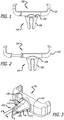
FIG. 1 illustrates an adjustable portable device holder in a retracted setting according to one embodiment; -
FIG. 2 illustrates an adjustable portable device holder in an expanded setting according to one embodiment; -
FIG. 3 illustrates an adjustable portable device holder in a retracted setting according to one embodiment; -
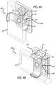
FIGS. 4A and 4B illustrate an adjustable portable device holder attached to a device and a mounting surface according to one embodiment; and -
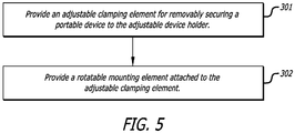
FIG. 5 illustrates a flow chart of a process for manufacturing an exemplary adjustable portable device holder according to one embodiment. - It will be appreciated that for simplicity and clarity of illustration, where considered appropriate, reference numerals may be repeated among the figures to indicate corresponding or analogous elements. In addition, numerous specific details are set forth in order to provide a thorough understanding of the example embodiments described herein. However, it will be understood by those of ordinary skill in the art that the example embodiments described herein may be practiced without these specific details. In other instances, methods, procedures and components have not been described in detail so as not to obscure the embodiments described herein.
- The adjustable portable device holders described in this specification can include an adjustable clamping element attached to a rotatable mounting element. The adjustable portable device holder can be used to attach and mount a portable device to a mounting surface. The portable device can be any device that fits into the adjustable clamping element including, but not limited to a smartphone or other phone, a tablet, an e-reader, a powerbank, a speaker, a multimedia player, a flashlight or other light, a television or other display, a laser or radar detector, an air freshener, a fan, a beverage or other device that can fit into the adjustable clamping element. The adjustable portable device holder can be mounted to various mounting surfaces including, but not limited to an automobile air conditioner vent blade, an automobile dashboard, an automobile sun visor, a credit card, the brim of a hat, a counter, a tripod, a bicycle, a backpack, a utensil, a ledge or other surface.
-
FIG. 1 illustrates an adjustableportable device holder 100 in a retracted setting according to one embodiment. The adjustableportable device holder 100 includes anadjustable clamping element 102 attached to arotatable mounting element 104. -
FIG. 2 illustrates an adjustableportable device holder 100 in an expanded setting according to one embodiment. The adjustableportable device holder 100 includes anadjustable clamping element 102 attached to arotatable mounting element 104. -
FIG. 3 illustrates an adjustableportable device holder 100 in a retracted setting according to one embodiment. The adjustableportable device holder 100 includes anadjustable clamping element 102 attached to arotatable mounting element 104. - The
adjustable clamping element 102 illustrated inFIGS. 1-3 can be expanded and retracted to attach devices of different sizes to the adjustableportable device holder 100. A force can be applied to expand or bias theadjustable clamping element 102 into an activated state (shown inFIG. 2 ) and the force can be released to retract theadjustable clamping element 102 into a deactivated state (shown inFIGS. 1 and 3 ). An elastic retracting or biasing element (not shown), such as a compression or torsion spring can be incorporated into theadjustable clamping element 102. The compression or torsion spring facilitates the expansion and retraction of theadjustable clamping element 102 upon applying or releasing a force on a surface of theadjustable clamping element 102. - The
adjustable clamping element 102 can also include a gripping material on a surface of theadjustable clamping element 102 to provide a better grip, a better viewing angle or better attachment to a device secured within theadjustable clamping element 102. The gripping material can be applied to a portion of theadjustable clamping element 102 or the entireadjustable clamping element 102 can be made of the gripping material. The gripping material can be any material that increases the adhesion, grip or coefficient of friction between the gripping surface of theadjustable clamping element 102 and a surface of a device secured within theadjustable clamping element 102. The gripping material can include, but is not limited to rubber, polymeric material or other plastic, metal, alloy, fabric, composite material or other material capable of increasing the adhesion, grip or coefficient of friction between the gripping surface of theadjustable clamping element 102 and a surface of a device secured within theadjustable clamping element 102. The gripping material and gripping surface can be textured and composed of the same or different material. - The
rotatable mounting element 104 illustrated inFIGS. 1-3 can be directly or indirectly attached to theadjustable clamping element 102. Theadjustable clamping element 102 and therotatable mounting element 104 can be one integral part or component parts that are attached together by any attaching means that allows therotatable mounting element 104 to rotate. Therotatable mounting element 104 includes abase plate 106 and a plurality of mountingarms 108 extending from thebase plate 106. Thebase plate 106 and the plurality of mountingarms 108 can be one integral part or component parts that are attached together by any attaching means. - Referring to
FIG. 3 , thebase plate 106 can be a cylindrically shaped disc or other element that is capable of being rotated 360 degrees clockwise or counter-clockwise. Thebase plate 106 provides a rotating platform from which mountingarms 108 extend. The mountingarms 108 are spaced a specified distance apart relative to one another on thebase plate 106. The mountingarms 108 also extend from thebase plate 106 at a specified angle relative to thebase plate 106. The size of the mountingarms 108, the distance between the mountingarms 108 and the angle at which the mountingarms 108 extend from thebase plate 106 establish and define mountingslots arms 108. The rotatable mountingelement 104 can include any number of mountingarms 108 and any number of mountingslots - The mounting
arms 108 can also include a gripping material on a surface of the mountingarms 108 to provide a better grip, a better viewing angle or better attachment to a mounting surface secured between the mountingarms 108. The gripping material can be applied to a portion of mountingarms 108 or the entirety of the mountingarms 108 can be made of the gripping material. The gripping material can be any material that increases the adhesion, grip or coefficient of friction between the gripping surface of mountingarms 108 and a mounting surface secured between the mountingarms 108. The gripping material can include, but is not limited to rubber, polymeric material or other plastic, metal, alloy, fabric, composite material or other material capable of increasing the adhesion, grip or coefficient of friction between the gripping surface of mountingarms 108 and a mounting surface secured between the mountingarms 108. The gripping material and gripping surface can be textured and composed of the same or different material. - In one exemplary embodiment, the
rotatable mounting element 104 includes four mounting arms and four mounting slots. In another exemplary embodiment, the rotating mountingelement 104 includes 6 mounting arms and six mounting slots. - The mounting
arms 108 and mountingslots portable device holder 100. The adjustableportable device holder 100 is mounted to a mounting surface by positioning, press fitting or wedging a mounting surface within one or more mountingslots arms 108. The adjustableportable device holder 100 can be mounted to various mounting surfaces including, but not limited to an automobile air conditioner vent blade, an automobile dashboard, an automobile sun visor, a credit card, the brim of a hat, a counter, a tripod, a bicycle, a backpack, a utensil, a ledge or other surface that can be positioned, press fit or wedged within one or more mountingslots arms 108. - The rotatable mounting
element 104 can include any number of mountingarms 108 forming and defining any number of mountingslots slots arms 108, the distance between the mountingarms 108 and the angle at which the mountingarms 108 extend from thebase plate 106. The rotatable mountingelement 104 can include one or more differentsize mounting slots FIG. 3 , one mountingslot 110 having clearance A can be larger than another mountingslot 112 having clearance B. One or more of the mountingslots 110 formed on therotatable mounting element 104 can accommodate a larger mounting surface than other mountingslots 112 formed on therotatable mounting element 104. - The rotatable mounting
element 104 can be rotated to position the mountingarms 108 and mountingslots arms 108 and mountingslots element 104. The rotatable mountingelement 104 can be rotated to position a relativelylarger mounting slot 110 with clearance A in a horizontal, vertical, diagonal, circular, concave or convex plane to engage a relatively larger mounting surface in a horizontal, vertical, diagonal, circular, concave or convex engagement plane. The rotatable mountingelement 104 can also be rotated to position a relativelysmaller mounting slot 112 with clearance B in a horizontal, vertical, diagonal, circular, concave or convex plane to engage a relatively smaller mounting surface in a horizontal, vertical, diagonal, circular, concave or convex engagement plane. - The rotatable mounting element is capable of being rotated 360 degrees clockwise or counter-clockwise to engage different size mounting surfaces in a horizontal plane, vertical plane, diagonal plane, circular plane, concave plane, convex plane or any plane between vertical and horizontal planes. A device attached to the adjustable
portable device holder 100 via theadjustable clamping element 102 can also be rotated 360 degrees clockwise or counter-clockwise while it is attached to the adjustableportable device holder 100 by rotating the rotatable mountingelement 104. -
FIGS. 4A and 4B illustrate an adjustableportable device holder 200 attached to adevice 214 and a mountingsurface 216 according to one embodiment. Thedevice 214 is a smart phone and the mountingsurface 216 is an automobile air conditioner vent blade. - Other portable devices can also fit into the adjustable clamping element including, but not limited to a tablet, an e-reader, a powerbank, a speaker, a multimedia player, a flashlight or other light, a television or other display, a laser or radar detector, an air freshener, a fan, a beverage or other device. The adjustable
portable device holder 200 can also be mounted to other mounting surfaces including, but not limited to an automobile dashboard, an automobile sun visor, a credit card, the brim of a hat, a counter, a tripod, a bicycle, a backpack, a utensil, a ledge or other surface. - The adjustable
portable device holder 200 includes anadjustable clamping element 202 attached to a rotatable mountingelement 204. Theadjustable clamping element 202 can be expanded and retracted to attach different size smartphones to the adjustableportable device holder 200. A force can be applied to expand or bias theadjustable clamping element 202 into an activated state and the force can be released to retract theadjustable clamping element 202 into a deactivated state to clamp around thesmartphone 214. An elastic retracting or biasing element (not shown), such as a compression or torsion spring can be incorporated into theadjustable clamping element 202 to facilitate the expansion and retraction of theadjustable clamping element 202 and to accommodate different size smartphones. - The
adjustable clamping element 202 can also include a gripping material on a surface of theadjustable clamping element 202 to provide a better grip, a better viewing angle or better attachment to thesmart phone 214 or other device secured within theadjustable clamping element 202. The gripping material can be applied to a portion of theadjustable clamping element 202 or the entireadjustable clamping element 202 can be made of the gripping material. The gripping material can be any material that increases the adhesion, grip or coefficient of friction between the gripping surface of theadjustable clamping element 202 and a surface of a device secured within theadjustable clamping element 202. The gripping material can include, but is not limited to rubber, polymeric material or other plastic, metal, alloy, fabric, composite material or other material capable of increasing the adhesion, grip or coefficient of friction between the gripping surface of theadjustable clamping element 202 and a surface of a device secured within theadjustable clamping element 202. The gripping material and gripping surface can be textured and composed of the same or different material. - The rotatable mounting
element 204 can be directly or indirectly attached to theadjustable clamping element 202. Theadjustable clamping element 202 and therotatable mounting element 204 can be one integral part or component parts that are attached together by any attaching means, such as a screw, ratchet, pin, rod or friction or other device that allows therotatable mounting element 204 to rotate. The rotatable mountingelement 204 includes abase plate 206 and a plurality of mounting arms 208 extending from thebase plate 206. Thebase plate 206 and the plurality of mounting arms 208 can be one integral part or component parts that are attached together by any attaching means. - The
base plate 206 can be a cylindrically shaped disc or other element that is capable of being rotated 360 degrees clockwise or counter-clockwise. Thebase plate 206 provides a rotating platform from which the mounting arms 208 extend. The mounting arms 208 are spaced a specified distance apart relative to one another on thebase plate 206. The mounting arms 208 also extend from thebase plate 206 at a specified angle relative to thebase plate 206. The size of the mounting arms 208, the distance between the mounting arms 208 and the angle at which the mounting arms 208 extend from thebase plate 206 establish and define mountingslots element 204 includes four mounting arms 208 and four mountingslots - The mounting arms 208 and mounting
slots conditioner vent blade 216 to mount the adjustableportable device holder 200. The adjustableportable device holder 200 is mounted to the airconditioner vent blade 216 by positioning, press fitting or wedging a surface of the airconditioner vent blade 216 within one or more mountingslots - The mounting arms 208 can also include a gripping material on a surface of the mounting arms 208 to provide a better grip, a better viewing angle or better attachment to the air
conditioner vent blade 216 secured between mounting arms 208. The gripping material can be applied to a portion of mounting arms 208 or the entirety of the mounting arms 208 can be made of the gripping material. The gripping material can be any material that increases the adhesion, grip or coefficient of friction between the gripping surface of mounting arms 208 and an airconditioner vent blade 216 secured between the mounting arms 208. The gripping material can include, but is not limited to rubber, polymeric material or other plastic, metal, alloy, fabric, composite material or other material capable of increasing the adhesion, grip or coefficient of friction between the gripping surface of mounting arms 208 and the airconditioner vent blade 216 secured between the mounting arms 208. The gripping material can be and gripping surface and composed of the same or different material. - The rotatable mounting
element 204 includes two different sizes of mountingslots conditioner vent blades 216 or other mounting surfaces. Two mountingslots 210 having clearance A are larger than the other two mountingslots 212 having clearance B. - The rotatable mounting
element 204 can be rotated to position the mounting arms 208 and mountingslots conditioner vent blades 216 oriented in a horizontal, vertical, diagonal, circular, concave, convex or any plane between vertical and horizontal planes. The mounting arms 208 and mountingslots element 204. The rotatable mountingelement 204 can be rotated to position the larger mountingslots 210 with clearance A in a horizontal, vertical, diagonal, circular, concave, convex or any plane between vertical and horizontal planes to engage or attach to larger airconditioner vent blades 216 oriented in a horizontal, vertical, diagonal, circular, concave, convex or any plane between vertical and horizontal planes. The rotatable mountingelement 204 can also be rotated to position the smaller mountingslots 212 with clearance B in a horizontal, vertical, diagonal, circular, concave, convex or any plane between vertical and horizontal planes to engage or attach to smaller airconditioner vent blades 216 oriented in a horizontal, vertical, diagonal, circular, concave, convex or any plane between vertical and horizontal planes. - The rotatable mounting
element 204 is capable of being rotated 360 degrees clockwise or counter-clockwise to engage different size mounting surfaces in a horizontal, vertical, diagonal, circular, concave, convex or any plane between vertical and horizontal planes relative to the force of gravity. Thesmart phone 214 attached to the adjustableportable device holder 200 can be rotated into a portrait orientation (shown inFIG. 4A ) and a landscape orientation (shown inFIG. 4B ) by rotating the rotatable mountingelement 204. Thesmart phone 214 attached to the adjustableportable device holder 200 can be rotated 360 degrees clockwise or counter-clockwise while it is attached to the adjustableportable device holder 200 by rotating thesmart phone 214 andadjustable clamping element 202, while therotatable mounting element 204 is secured to a mounting surface. -
FIG. 5 illustrates a flow chart of a process for manufacturing an exemplary adjustable portable device holder according to one embodiment. Atstep 301, the process includes providing an adjustable clamping element for removably securing a portable device to the adjustable portable device holder. The adjustable clamping element is capable of being biased into an activated state and unbiased into a deactivated state to secure one of a plurality of different size portable device to the adjustable portable device holder. - For example, to manufacture the adjustable portable device holder, two stainless steel rods can be inserted into an expandable arm cavity of a double injection mold. PC/ABS is injected into the cavities of the mold to hold the rods in place and to produce an expandable arm, main body and cover of an adjustable clamping element. The mold is then rotated and injected with TPE to form side grips of the expandable arm and body of the adjustable clamping element. A stainless steel spring is inserted over each rod and held in place by a stainless steel screw affixed to the end of the rods. Grease is added to the lower portion of the spring and rods (near the screw head). The expandable arm is inserted into the body and the springs are lowered and held in place within the body of the adjustable clamping element. The cover is the slid on to the body to hold the adjustable arm in place.
- The adjustable clamping element or a surface thereof can also be formed from rubber, polymeric material or other plastic, metal, alloy, or composite material that is rigid, semi-rigid or textured.
- At
step 302, a rotatable mounting element is provided, which can be attached to the adjustable clamping element via screw, ratchet, pin, rod or friction or other attachment means. The rotatable mounting element includes a plurality of mounting arms each spaced a specified distance apart from one another and extending at a specified angle from a bottom surface of the rotatable mounting element. Each pair of the plurality of mounting arms form a mounting slot therein between. The rotatable mounting element is capable of being rotated to position a first mounting slot in a vertical, horizontal or diagonal orientation and a second mounting slot in a vertical, horizontal or diagonal orientation to engage a first mounting surface in a vertical, horizontal or diagonal orientation or a second mounting surface in a vertical, horizontal or diagonal orientation. - For example, and a rotatable mounting element can be formed in whole or part from stainless metal or other metal, alloy or plastic sheet stamped to form a clip or base plate with four arms extending from the base plate, spaced a specified distance apart and bent to a desired angle. If metal or other heat treatable material, the rotatable mounting element can be heat treated to form a rigid structure. The rotatable mounting element or a surface thereof can also be formed from rubber, polymeric material or other plastic, metal, alloy, or composite material that is rigid, semi-rigid or textured.
- A zinc-alloy nut or other alloy or material can be formed using a die-cast mold to attach the rotatable mounting element to the adjustable clamping element. Glue is added to the cavity of the nut. The rotatable mounting element is affixed to the main body of the adjustable clamping element via the nut and a second stainless screw. A force gage is used to monitor the rotational force of the rotatable mounting element and the rotatable mounting element is adjusted if screw is too tight or loose.
- TPE is injected into a mold to create a skirt and four socks. The skirt and four socks can also be formed from rubber, polymeric material or other plastic, metal, alloy, or composite material that is rigid, semi-rigid or textured. The skirt is assembled over the mounting arms of the rotatable mounting element. Glue is added to each mounting arm of the rotatable mounting element. A sock is inserted over each mounting arm, which holds the skirt in place.
- Example embodiments have been described hereinabove regarding adjustable portable device holder systems and methods. Various modifications to and departures from the disclosed example embodiments will occur to those having ordinary skill in the art. The subject matter that is intended to be within the spirit of this disclosure is set forth in the following claims.
Claims (15)
- An adjustable portable device holder (100, 200) comprising:an adjustable clamping element (102, 202) that can be expanded and retracted to secure portable electronic devices of different sizes to the adjustable portable device holder (100, 200);the adjustable clamping element including a compression or torsion spring that facilitates expansion and retraction of the adjustable clamping element (102, 202) upon applying or releasing a force on a surface of the adjustable clamping element (102, 202);a rotatable mounting element (104, 204) attached to the adjustable clamping element (102, 202);the rotatable mounting element (104, 204) including a base plate (106, 206) and a plurality of mounting arms (108, 208) extending from the base plate (106, 206);the base plate (106, 206) providing a rotating platform from which the mounting arms (106, 208) extend;the mounting arms (108, 208) spaced a distance apart relative to one another and extending from the base plate (106, 206) at an angle relative to the base plate (106, 206), and defining a mounting slot (110, 112, 210, 212) between the mounting arms (108, 208);the mounting slot (110, 112, 210, 212) between the mounting arms (108, 208) configured to engage and attach to an automobile air conditioner vent blade to mount the adjustable portable device holder (100, 200); andthe mounting arms of the rotatable mounting element (104, 204) including a gripping material on a gripping surface of the mounting arms to increase an adhesion, grip or coefficient of friction between the gripping surface of mounting arms (108, 208) and an automobile air conditioner vent blade secured within the mounting slot (110, 112, 210, 212) between the mounting arms (108, 208).
- The adjustable portable device holder (100, 200) claim 1, wherein the rotatable mounting element (104, 204) formed in whole or part from a metal, alloy or plastic sheet stamped to form the base plate (106, 206) with arms extending from the base plate, spaced a distance apart from one another and bent at an angle relative to the base plate to form the mounting arms (108, 208); and
- The adjustable portable device holder (100, 200) of claim 1 or 2, wherein the base plate (106, 206) comprises a cylindrically shaped disc or other element that is capable of being rotated clockwise or counter-clockwise; and further comprising a screw, ratchet, pin or rod that attaches the rotatable mounting element (104, 204) to the adjustable clamping element (102, 202) and that allows the rotatable mounting element (104, 204) to rotate.
- The adjustable portable device holder (100, 200) of claim 1 or 2, wherein injection molded socks are inserted over the mounting arms (108, 208) of the rotatable mounting element (104, 204).
- The adjustable portable device holder (100, 200) of claim 1 or 2, wherein an injection molded skirt is assembled over the mounting arms (108, 208) of the rotatable mounting element (104, 204), and injection molded socks are inserted over the mounting arms and hold the skirt in place.
- The adjustable portable device holder (100, 200) of claim 1 or 2, wherein the rotatable mounting element (104, 204) enables a portable electronic device that is secured within the adjustable clamping element (102, 202) to be rotated clockwise or counter-clockwise into a portrait orientation and a landscape orientation while the rotatable mounting element (104, 204) is secured to an automobile air conditioner vent blade.
- The adjustable portable device holder (100, 200) of claim 1 or 2, wherein the mounting arms (108, 208) define multiple mounting slots (110, 112, 210, 212) including a first mounting slot (110, 210) having first clearance and a second mounting slot (112, 212) having second clearance, wherein the first clearance is larger than the second clearance.
- The adjustable portable device holder (100, 200) of claim 7, wherein:the rotatable mounting element (104, 204) can be rotated to position the first mounting slot (110, 210) having the first clearance in a horizontal, vertical, or diagonal plane to secure the first mounting slot (110, 210) to larger automobile air conditioner vent blades oriented in a horizontal, vertical or diagonal plane; andthe rotatable mounting element (104, 204) can be rotated to position the second mounting slot (112, 212) having the second clearance in a horizontal, vertical, or diagonal plane to secure the second mounting slot (112, 212) to smaller automobile air conditioner vent blades oriented in a horizontal, vertical or diagonal plane.
- The adjustable portable device holder (100, 200) claim 1 or 2, wherein the gripping material comprises a rubber, polymeric material or other plastic, metal, alloy, fabric, composite material that increases the adhesion, grip or coefficient of friction between the gripping surface of mounting arms (108, 208) and an automobile air conditioner vent blade secured between the mounting arms (108, 208).
- The adjustable portable device holder (100, 200) claim 1 or 2, wherein:the adjustable clamping element (102, 202) includes a gripping material on a surface of the adjustable clamping element (102, 202) to increase an adhesion, grip or coefficient of friction between the gripping surface of adjustable clamping element and a surface of a portable electronic device secured within the adjustable clamping element (102, 202); andthe gripping material on the surface of the adjustable clamping element (102, 202) comprises a rubber, polymeric material or other plastic, metal, alloy, fabric, composite material that increases the adhesion, grip or coefficient of friction between the gripping surface of mounting arms (108, 208) and an automobile air conditioner vent blade secured between the mounting arms (108, 208).
- The adjustable portable device holder (100, 200) of claim 1 or 2, wherein:the base plate (106, 206) of the rotatable mounting element (104, 204) is attached to a main body of the adjustable clamping element (102, 202);when the adjustable clamping element (102, 202) is completely retracted, a portion of the adjustable clamping element (102, 202) from which a side grip extends is flush with a side portion of the main body; andwhen the adjustable clamping element (102, 202) is expanded, the portion of the adjustable clamping element from which the side grip extends is no longer flush with the side portion of the main body.
- The adjustable portable device holder (100, 200) of claim 11, wherein the portion of the adjustable clamping element from which the side grip extends comprises an expandable arm.
- The adjustable portable device holder (100, 200) of claim 12, further comprising two rods inserted into the expandable arm.
- The adjustable portable device holder (100, 200) of claim 13, wherein:when the adjustable clamping element (102, 202) is completely retracted the rods are not exposed and are thereby not viewable; andwhen the adjustable clamping element (102, 202) is expanded there is a gap, between the main body and the adjustable arm of the adjustable clamping element, with the rods exposed and thereby viewable within the gap.
- The adjustable portable device holder (100, 200) of claim 1, wherein:the adjustable clamping element (102, 202) is configured to engage only two of four peripherals sides of a portable electronic device that is secured within the adjustable clamping element (102, 202); andwherein portable electronic devices of different sizes that can be secured within the adjustable clamping element (102, 202) of the adjustable portable device holder (100, 200) comprise different size smartphones.
Applications Claiming Priority (2)
| Application Number | Priority Date | Filing Date | Title |
|---|---|---|---|
| US13/897,062 US9080714B2 (en) | 2012-11-20 | 2013-05-17 | Adjustable portable device holder |
| EP14798238.3A EP2997438B1 (en) | 2013-05-17 | 2014-05-15 | Adjustable portable device holder |
Related Parent Applications (1)
| Application Number | Title | Priority Date | Filing Date |
|---|---|---|---|
| EP14798238.3A Division EP2997438B1 (en) | 2013-05-17 | 2014-05-15 | Adjustable portable device holder |
Publications (2)
| Publication Number | Publication Date |
|---|---|
| EP3244283A1 true EP3244283A1 (en) | 2017-11-15 |
| EP3244283B1 EP3244283B1 (en) | 2018-06-27 |
Family
ID=51898882
Family Applications (2)
| Application Number | Title | Priority Date | Filing Date |
|---|---|---|---|
| EP14798238.3A Active EP2997438B1 (en) | 2013-05-17 | 2014-05-15 | Adjustable portable device holder |
| EP17178044.8A Not-in-force EP3244283B1 (en) | 2013-05-17 | 2014-05-15 | Adjustable portable device holder |
Family Applications Before (1)
| Application Number | Title | Priority Date | Filing Date |
|---|---|---|---|
| EP14798238.3A Active EP2997438B1 (en) | 2013-05-17 | 2014-05-15 | Adjustable portable device holder |
Country Status (17)
| Country | Link |
|---|---|
| EP (2) | EP2997438B1 (en) |
| JP (1) | JP5976238B2 (en) |
| KR (1) | KR101660669B1 (en) |
| CN (2) | CN107415844A (en) |
| AU (1) | AU2014265355B2 (en) |
| BR (1) | BR112015018915A8 (en) |
| CA (1) | CA2903424C (en) |
| DK (1) | DK2997438T3 (en) |
| ES (2) | ES2639497T3 (en) |
| HK (1) | HK1217552A1 (en) |
| HU (1) | HUE033691T2 (en) |
| IL (1) | IL240308A0 (en) |
| MX (1) | MX346357B (en) |
| PL (1) | PL2997438T3 (en) |
| PT (1) | PT2997438T (en) |
| RU (1) | RU2601253C1 (en) |
| WO (1) | WO2014186609A1 (en) |
Cited By (1)
| Publication number | Priority date | Publication date | Assignee | Title |
|---|---|---|---|---|
| US11097665B2 (en) | 2017-06-01 | 2021-08-24 | Pioneer Corporation | Holding mechanism and holding device |
Families Citing this family (15)
| Publication number | Priority date | Publication date | Assignee | Title |
|---|---|---|---|---|
| CN107404555A (en) * | 2016-05-21 | 2017-11-28 | 麦广树 | Handset mounting with width adaptive mechanism |
| CN105978675B (en) * | 2016-06-24 | 2019-01-08 | 西安电子科技大学 | Based on orthogonal frequency division multiple access up-link access method |
| CN106051393A (en) * | 2016-07-11 | 2016-10-26 | 深圳天珑无线科技有限公司 | Flexible display and bracket thereof |
| KR101934023B1 (en) * | 2016-08-29 | 2019-01-16 | 김세한 | Apparatus for holding portable device |
| CN106231029A (en) * | 2016-08-31 | 2016-12-14 | 深圳多哚新技术有限责任公司 | A kind of virtual reality device |
| KR200489241Y1 (en) * | 2017-12-20 | 2019-05-21 | (주)가나웨이브시스 | Portable holder for vehicle |
| CN108061220B (en) * | 2017-12-22 | 2019-09-24 | 山东广域科技有限责任公司 | A kind of power communication detection maintenance device |
| KR101854099B1 (en) * | 2018-01-31 | 2018-06-08 | 김재문 | Cell phone supporter of fixed to air vent |
| US10782803B2 (en) | 2018-02-19 | 2020-09-22 | Dillon Markey | Ergonomic bike grip controller |
| CN109185678A (en) * | 2018-11-05 | 2019-01-11 | 柳小佳 | A kind of method that mobile electronic device fixes bracket and adjusts clamp position |
| JP7313043B2 (en) * | 2019-08-05 | 2023-07-24 | 槌屋ヤック株式会社 | automotive smartphone holder |
| CN112550170A (en) * | 2020-12-02 | 2021-03-26 | 宋福存 | Vehicle-mounted mobile phone support capable of being rotationally positioned |
| KR102291192B1 (en) * | 2020-12-15 | 2021-08-18 | 김영수 | Digital device holder |
| CN113511151A (en) * | 2021-08-21 | 2021-10-19 | 深圳市福伦达精工技术有限公司 | Intelligent diagnostic instrument for automobile |
| CN114056241B (en) * | 2021-11-23 | 2023-08-01 | 浙江极氪智能科技有限公司 | Mounting and have its glove box |
Citations (4)
| Publication number | Priority date | Publication date | Assignee | Title |
|---|---|---|---|---|
| US5305381A (en) * | 1992-11-09 | 1994-04-19 | Wang Chin Y | Cradle for telephone |
| DE202004007340U1 (en) * | 2004-05-07 | 2004-07-22 | Chang, Ta-Shuo | Holding arrangement for fitting to motor vehicle fan grid has |
| EP1902736A1 (en) * | 2006-09-19 | 2008-03-26 | Sara Lee/DE N.V. | Dual scent air-freshening dispensing device |
| CN202907016U (en) * | 2012-09-26 | 2013-04-24 | 毛亚丽 | Mobile phone base |
Family Cites Families (29)
| Publication number | Priority date | Publication date | Assignee | Title |
|---|---|---|---|---|
| CN2150682Y (en) * | 1993-02-22 | 1993-12-22 | 王进杨 | Holder for movable telephone |
| IT1273739B (en) * | 1994-07-29 | 1997-07-09 | Marco Valerio Masi | EASY REMOVABLE SUPPORT FOR THE SUPPORT OF A MOBILE PHONE INSIDE A VEHICLE |
| CN2212864Y (en) * | 1994-09-21 | 1995-11-15 | 怡利电子工业股份有限公司 | Receiver rest without holding |
| US6103201A (en) * | 1995-07-25 | 2000-08-15 | Green; Dennis E. | Propeller air freshener |
| KR20000044438A (en) * | 1998-12-30 | 2000-07-15 | 윤종용 | Holder for hand-free kit |
| ATE348721T1 (en) * | 1999-02-25 | 2007-01-15 | Sara Lee De Nv | AIR FRESHENER |
| US6366672B1 (en) * | 1999-11-10 | 2002-04-02 | Wen-Feng Tsay | Mobile phone holder |
| CN2438620Y (en) * | 2000-08-17 | 2001-07-11 | 高而富股份有限公司 | Mobile telephone holder |
| JP4739601B2 (en) * | 2001-08-17 | 2011-08-03 | 株式会社ナポレックス | Mounting tool for air conditioner outlet louver of article holder |
| US6441872B1 (en) * | 2001-10-15 | 2002-08-27 | Photic Electronics Co., Ltd. | Vehicle reversal monitoring device mounting fixture |
| JP4108987B2 (en) * | 2002-02-07 | 2008-06-25 | 星光産業株式会社 | Retainer |
| US7650230B1 (en) * | 2003-03-26 | 2010-01-19 | Garmin Ltd. | Navigational device for mounting on a support pillar of a vehicle and a method for doing same |
| US7080812B2 (en) * | 2004-01-17 | 2006-07-25 | Belkin Corporation | Holding device for holding a portable object, and method of manufacturing same |
| US6988907B2 (en) * | 2004-03-03 | 2006-01-24 | Ta-Shuo Chang | Sectional adapter of clamping holder for automobiles |
| US7537190B2 (en) * | 2006-06-13 | 2009-05-26 | Eagle Fan | Holding device for electronic apparatus |
| KR200429528Y1 (en) * | 2006-08-14 | 2006-10-24 | (주)정인일렉텍 | A phone mounting device with fragrance |
| US20080190978A1 (en) * | 2007-02-14 | 2008-08-14 | Paul Brassard | Mounting apparatus |
| JP2008202771A (en) * | 2007-02-19 | 2008-09-04 | Napolex Co | Article holder |
| RU2461474C1 (en) * | 2008-07-01 | 2012-09-20 | Вольво Ластвагнар Аб | Automotive monitor holder |
| DE202008010276U1 (en) * | 2008-07-31 | 2008-11-20 | COMART Corporation, Sindian City | Adjustment device for mounting in the vehicle |
| CN101674096B (en) * | 2008-09-12 | 2013-03-13 | 汪玉华 | Stand for placing and charging mobile phone and bluetooth earphones |
| JP3151546U (en) * | 2009-04-16 | 2009-06-25 | 株式会社セイワ | Article holder |
| US8202114B2 (en) * | 2009-12-14 | 2012-06-19 | Mitac International Corp. | Mobile phone cradle with three-point retention of portable electronic device installed in the cradle |
| CN201633647U (en) * | 2010-01-09 | 2010-11-17 | 励勋儿 | Mobile phone holder used in vehicles |
| JP3164223U (en) * | 2010-09-07 | 2010-11-18 | 株式会社セイワ | Article holder |
| US8235334B1 (en) * | 2011-02-16 | 2012-08-07 | Mark Kobal | Tablet computer holder and support |
| KR20120125933A (en) * | 2011-05-09 | 2012-11-19 | 오치완 | Phone holder equipped with air freshener/ ash tray |
| US20130037590A1 (en) * | 2011-08-12 | 2013-02-14 | Namsung Co., Ltd. | Holder apparatus for mounting a media device in a vehicle |
| US9103487B2 (en) * | 2012-03-24 | 2015-08-11 | Daymen Us, Inc. | Adjustable mounting clip and system using same |
-
2014
- 2014-05-15 KR KR1020157035564A patent/KR101660669B1/en active IP Right Grant
- 2014-05-15 BR BR112015018915A patent/BR112015018915A8/en not_active Application Discontinuation
- 2014-05-15 CA CA2903424A patent/CA2903424C/en not_active Expired - Fee Related
- 2014-05-15 WO PCT/US2014/038253 patent/WO2014186609A1/en active Application Filing
- 2014-05-15 ES ES14798238.3T patent/ES2639497T3/en active Active
- 2014-05-15 EP EP14798238.3A patent/EP2997438B1/en active Active
- 2014-05-15 CN CN201710153065.3A patent/CN107415844A/en active Pending
- 2014-05-15 PT PT147982383T patent/PT2997438T/en unknown
- 2014-05-15 RU RU2015137589/28A patent/RU2601253C1/en not_active IP Right Cessation
- 2014-05-15 JP JP2015557246A patent/JP5976238B2/en not_active Expired - Fee Related
- 2014-05-15 HU HUE14798238A patent/HUE033691T2/en unknown
- 2014-05-15 DK DK14798238.3T patent/DK2997438T3/en active
- 2014-05-15 MX MX2015015365A patent/MX346357B/en active IP Right Grant
- 2014-05-15 CN CN201480019028.8A patent/CN105229557B/en active Active
- 2014-05-15 ES ES17178044.8T patent/ES2685771T3/en active Active
- 2014-05-15 PL PL14798238T patent/PL2997438T3/en unknown
- 2014-05-15 AU AU2014265355A patent/AU2014265355B2/en not_active Ceased
- 2014-05-15 EP EP17178044.8A patent/EP3244283B1/en not_active Not-in-force
-
2015
- 2015-08-02 IL IL240308A patent/IL240308A0/en not_active IP Right Cessation
-
2016
- 2016-05-16 HK HK16105582.5A patent/HK1217552A1/en not_active IP Right Cessation
Patent Citations (4)
| Publication number | Priority date | Publication date | Assignee | Title |
|---|---|---|---|---|
| US5305381A (en) * | 1992-11-09 | 1994-04-19 | Wang Chin Y | Cradle for telephone |
| DE202004007340U1 (en) * | 2004-05-07 | 2004-07-22 | Chang, Ta-Shuo | Holding arrangement for fitting to motor vehicle fan grid has |
| EP1902736A1 (en) * | 2006-09-19 | 2008-03-26 | Sara Lee/DE N.V. | Dual scent air-freshening dispensing device |
| CN202907016U (en) * | 2012-09-26 | 2013-04-24 | 毛亚丽 | Mobile phone base |
Cited By (2)
| Publication number | Priority date | Publication date | Assignee | Title |
|---|---|---|---|---|
| US11097665B2 (en) | 2017-06-01 | 2021-08-24 | Pioneer Corporation | Holding mechanism and holding device |
| US11661015B2 (en) | 2017-06-01 | 2023-05-30 | Pioneer Corporation | Holding mechanism and holding device |
Also Published As
| Publication number | Publication date |
|---|---|
| DK2997438T3 (en) | 2017-09-11 |
| RU2601253C1 (en) | 2016-10-27 |
| HK1217552A1 (en) | 2017-01-13 |
| EP2997438B1 (en) | 2017-06-28 |
| PL2997438T3 (en) | 2017-12-29 |
| KR20160005126A (en) | 2016-01-13 |
| MX346357B (en) | 2017-03-15 |
| MX2015015365A (en) | 2016-03-04 |
| EP2997438A4 (en) | 2016-05-04 |
| AU2014265355B2 (en) | 2015-10-01 |
| PT2997438T (en) | 2017-09-13 |
| CA2903424C (en) | 2016-04-26 |
| KR101660669B1 (en) | 2016-09-27 |
| CN105229557B (en) | 2017-04-05 |
| BR112015018915A8 (en) | 2019-11-05 |
| EP3244283B1 (en) | 2018-06-27 |
| CA2903424A1 (en) | 2014-11-20 |
| CN105229557A (en) | 2016-01-06 |
| CN107415844A (en) | 2017-12-01 |
| EP2997438A1 (en) | 2016-03-23 |
| BR112015018915A2 (en) | 2017-07-18 |
| ES2639497T3 (en) | 2017-10-26 |
| HUE033691T2 (en) | 2017-12-28 |
| IL240308A (en) | 2015-10-29 |
| JP2016513218A (en) | 2016-05-12 |
| IL240308A0 (en) | 2015-10-29 |
| JP5976238B2 (en) | 2016-08-24 |
| WO2014186609A1 (en) | 2014-11-20 |
| AU2014265355A1 (en) | 2015-09-17 |
| ES2685771T3 (en) | 2018-10-11 |
Similar Documents
| Publication | Publication Date | Title |
|---|---|---|
| US10315585B2 (en) | Adjustable portable device holder | |
| EP3244283B1 (en) | Adjustable portable device holder | |
| US20180043840A1 (en) | Portable device holder | |
| US20170314732A1 (en) | Apparatuses that provide a mount and a stand for portable electronic devices | |
| US20170313260A1 (en) | Apparatuses for mounting portable electronic devices in vehicles | |
| AU2015101592A4 (en) | Magnetic Universal Mounting Assembly | |
| US20160174396A1 (en) | Holder having adjustable clamping orientation | |
| US10583790B2 (en) | Adjustable electronic device mount | |
| CN204358358U (en) | A kind of magnetic-type simple and easy The Cloud Terrace | |
| TWM559973U (en) | Clamp for automobile air conditioning outlet | |
| CN108533895B (en) | Support frame | |
| KR101954704B1 (en) | Holder for vehicles | |
| KR200476543Y1 (en) | a holding apparatus for mobile device | |
| CN211344541U (en) | Screen support and vehicle | |
| CN204741499U (en) | Can install multi -functional camera on multiple object | |
| CN215398440U (en) | Blind area viewing device of automobile rearview mirror | |
| CN207652512U (en) | Telescopic mobile phone holder | |
| CA2776515A1 (en) | Tablet and smart phone support stand for desktop and dashboard and clamp for tripod |
Legal Events
| Date | Code | Title | Description |
|---|---|---|---|
| PUAI | Public reference made under article 153(3) epc to a published international application that has entered the european phase |
Free format text: ORIGINAL CODE: 0009012 |
|
| STAA | Information on the status of an ep patent application or granted ep patent |
Free format text: STATUS: REQUEST FOR EXAMINATION WAS MADE |
|
| 17P | Request for examination filed |
Effective date: 20170627 |
|
| AC | Divisional application: reference to earlier application |
Ref document number: 2997438 Country of ref document: EP Kind code of ref document: P |
|
| AK | Designated contracting states |
Kind code of ref document: A1 Designated state(s): AL AT BE BG CH CY CZ DE DK EE ES FI FR GB GR HR HU IE IS IT LI LT LU LV MC MK MT NL NO PL PT RO RS SE SI SK SM TR |
|
| GRAP | Despatch of communication of intention to grant a patent |
Free format text: ORIGINAL CODE: EPIDOSNIGR1 |
|
| STAA | Information on the status of an ep patent application or granted ep patent |
Free format text: STATUS: GRANT OF PATENT IS INTENDED |
|
| INTG | Intention to grant announced |
Effective date: 20180403 |
|
| GRAS | Grant fee paid |
Free format text: ORIGINAL CODE: EPIDOSNIGR3 |
|
| GRAA | (expected) grant |
Free format text: ORIGINAL CODE: 0009210 |
|
| STAA | Information on the status of an ep patent application or granted ep patent |
Free format text: STATUS: THE PATENT HAS BEEN GRANTED |
|
| AC | Divisional application: reference to earlier application |
Ref document number: 2997438 Country of ref document: EP Kind code of ref document: P |
|
| AK | Designated contracting states |
Kind code of ref document: B1 Designated state(s): AL AT BE BG CH CY CZ DE DK EE ES FI FR GB GR HR HU IE IS IT LI LT LU LV MC MK MT NL NO PL PT RO RS SE SI SK SM TR |
|
| REG | Reference to a national code |
Ref country code: GB Ref legal event code: FG4D |
|
| REG | Reference to a national code |
Ref country code: AT Ref legal event code: REF Ref document number: 1012869 Country of ref document: AT Kind code of ref document: T Effective date: 20180715 |
|
| REG | Reference to a national code |
Ref country code: IE Ref legal event code: FG4D |
|
| REG | Reference to a national code |
Ref country code: DE Ref legal event code: R096 Ref document number: 602014027730 Country of ref document: DE |
|
| REG | Reference to a national code |
Ref country code: ES Ref legal event code: FG2A Ref document number: 2685771 Country of ref document: ES Kind code of ref document: T3 Effective date: 20181011 |
|
| PG25 | Lapsed in a contracting state [announced via postgrant information from national office to epo] |
Ref country code: FI Free format text: LAPSE BECAUSE OF FAILURE TO SUBMIT A TRANSLATION OF THE DESCRIPTION OR TO PAY THE FEE WITHIN THE PRESCRIBED TIME-LIMIT Effective date: 20180627 Ref country code: BG Free format text: LAPSE BECAUSE OF FAILURE TO SUBMIT A TRANSLATION OF THE DESCRIPTION OR TO PAY THE FEE WITHIN THE PRESCRIBED TIME-LIMIT Effective date: 20180927 Ref country code: SE Free format text: LAPSE BECAUSE OF FAILURE TO SUBMIT A TRANSLATION OF THE DESCRIPTION OR TO PAY THE FEE WITHIN THE PRESCRIBED TIME-LIMIT Effective date: 20180627 Ref country code: NO Free format text: LAPSE BECAUSE OF FAILURE TO SUBMIT A TRANSLATION OF THE DESCRIPTION OR TO PAY THE FEE WITHIN THE PRESCRIBED TIME-LIMIT Effective date: 20180927 Ref country code: LT Free format text: LAPSE BECAUSE OF FAILURE TO SUBMIT A TRANSLATION OF THE DESCRIPTION OR TO PAY THE FEE WITHIN THE PRESCRIBED TIME-LIMIT Effective date: 20180627 |
|
| REG | Reference to a national code |
Ref country code: NL Ref legal event code: MP Effective date: 20180627 |
|
| REG | Reference to a national code |
Ref country code: LT Ref legal event code: MG4D |
|
| PG25 | Lapsed in a contracting state [announced via postgrant information from national office to epo] |
Ref country code: GR Free format text: LAPSE BECAUSE OF FAILURE TO SUBMIT A TRANSLATION OF THE DESCRIPTION OR TO PAY THE FEE WITHIN THE PRESCRIBED TIME-LIMIT Effective date: 20180928 Ref country code: HR Free format text: LAPSE BECAUSE OF FAILURE TO SUBMIT A TRANSLATION OF THE DESCRIPTION OR TO PAY THE FEE WITHIN THE PRESCRIBED TIME-LIMIT Effective date: 20180627 Ref country code: RS Free format text: LAPSE BECAUSE OF FAILURE TO SUBMIT A TRANSLATION OF THE DESCRIPTION OR TO PAY THE FEE WITHIN THE PRESCRIBED TIME-LIMIT Effective date: 20180627 Ref country code: LV Free format text: LAPSE BECAUSE OF FAILURE TO SUBMIT A TRANSLATION OF THE DESCRIPTION OR TO PAY THE FEE WITHIN THE PRESCRIBED TIME-LIMIT Effective date: 20180627 |
|
| REG | Reference to a national code |
Ref country code: AT Ref legal event code: MK05 Ref document number: 1012869 Country of ref document: AT Kind code of ref document: T Effective date: 20180627 |
|
| PG25 | Lapsed in a contracting state [announced via postgrant information from national office to epo] |
Ref country code: NL Free format text: LAPSE BECAUSE OF FAILURE TO SUBMIT A TRANSLATION OF THE DESCRIPTION OR TO PAY THE FEE WITHIN THE PRESCRIBED TIME-LIMIT Effective date: 20180627 |
|
| PG25 | Lapsed in a contracting state [announced via postgrant information from national office to epo] |
Ref country code: CZ Free format text: LAPSE BECAUSE OF FAILURE TO SUBMIT A TRANSLATION OF THE DESCRIPTION OR TO PAY THE FEE WITHIN THE PRESCRIBED TIME-LIMIT Effective date: 20180627 Ref country code: PL Free format text: LAPSE BECAUSE OF FAILURE TO SUBMIT A TRANSLATION OF THE DESCRIPTION OR TO PAY THE FEE WITHIN THE PRESCRIBED TIME-LIMIT Effective date: 20180627 Ref country code: EE Free format text: LAPSE BECAUSE OF FAILURE TO SUBMIT A TRANSLATION OF THE DESCRIPTION OR TO PAY THE FEE WITHIN THE PRESCRIBED TIME-LIMIT Effective date: 20180627 Ref country code: AT Free format text: LAPSE BECAUSE OF FAILURE TO SUBMIT A TRANSLATION OF THE DESCRIPTION OR TO PAY THE FEE WITHIN THE PRESCRIBED TIME-LIMIT Effective date: 20180627 Ref country code: IS Free format text: LAPSE BECAUSE OF FAILURE TO SUBMIT A TRANSLATION OF THE DESCRIPTION OR TO PAY THE FEE WITHIN THE PRESCRIBED TIME-LIMIT Effective date: 20181027 Ref country code: RO Free format text: LAPSE BECAUSE OF FAILURE TO SUBMIT A TRANSLATION OF THE DESCRIPTION OR TO PAY THE FEE WITHIN THE PRESCRIBED TIME-LIMIT Effective date: 20180627 Ref country code: SK Free format text: LAPSE BECAUSE OF FAILURE TO SUBMIT A TRANSLATION OF THE DESCRIPTION OR TO PAY THE FEE WITHIN THE PRESCRIBED TIME-LIMIT Effective date: 20180627 |
|
| PG25 | Lapsed in a contracting state [announced via postgrant information from national office to epo] |
Ref country code: SM Free format text: LAPSE BECAUSE OF FAILURE TO SUBMIT A TRANSLATION OF THE DESCRIPTION OR TO PAY THE FEE WITHIN THE PRESCRIBED TIME-LIMIT Effective date: 20180627 |
|
| REG | Reference to a national code |
Ref country code: DE Ref legal event code: R097 Ref document number: 602014027730 Country of ref document: DE |
|
| PLBE | No opposition filed within time limit |
Free format text: ORIGINAL CODE: 0009261 |
|
| STAA | Information on the status of an ep patent application or granted ep patent |
Free format text: STATUS: NO OPPOSITION FILED WITHIN TIME LIMIT |
|
| PG25 | Lapsed in a contracting state [announced via postgrant information from national office to epo] |
Ref country code: DK Free format text: LAPSE BECAUSE OF FAILURE TO SUBMIT A TRANSLATION OF THE DESCRIPTION OR TO PAY THE FEE WITHIN THE PRESCRIBED TIME-LIMIT Effective date: 20180627 |
|
| 26N | No opposition filed |
Effective date: 20190328 |
|
| PGFP | Annual fee paid to national office [announced via postgrant information from national office to epo] |
Ref country code: IT Payment date: 20190510 Year of fee payment: 6 Ref country code: ES Payment date: 20190604 Year of fee payment: 6 |
|
| PG25 | Lapsed in a contracting state [announced via postgrant information from national office to epo] |
Ref country code: SI Free format text: LAPSE BECAUSE OF FAILURE TO SUBMIT A TRANSLATION OF THE DESCRIPTION OR TO PAY THE FEE WITHIN THE PRESCRIBED TIME-LIMIT Effective date: 20180627 |
|
| PGFP | Annual fee paid to national office [announced via postgrant information from national office to epo] |
Ref country code: FR Payment date: 20190429 Year of fee payment: 6 |
|
| PGFP | Annual fee paid to national office [announced via postgrant information from national office to epo] |
Ref country code: DE Payment date: 20190624 Year of fee payment: 6 Ref country code: GB Payment date: 20190429 Year of fee payment: 6 |
|
| PG25 | Lapsed in a contracting state [announced via postgrant information from national office to epo] |
Ref country code: AL Free format text: LAPSE BECAUSE OF FAILURE TO SUBMIT A TRANSLATION OF THE DESCRIPTION OR TO PAY THE FEE WITHIN THE PRESCRIBED TIME-LIMIT Effective date: 20180627 |
|
| REG | Reference to a national code |
Ref country code: CH Ref legal event code: PL |
|
| PG25 | Lapsed in a contracting state [announced via postgrant information from national office to epo] |
Ref country code: MC Free format text: LAPSE BECAUSE OF FAILURE TO SUBMIT A TRANSLATION OF THE DESCRIPTION OR TO PAY THE FEE WITHIN THE PRESCRIBED TIME-LIMIT Effective date: 20180627 Ref country code: CH Free format text: LAPSE BECAUSE OF NON-PAYMENT OF DUE FEES Effective date: 20190531 Ref country code: LI Free format text: LAPSE BECAUSE OF NON-PAYMENT OF DUE FEES Effective date: 20190531 |
|
| REG | Reference to a national code |
Ref country code: BE Ref legal event code: MM Effective date: 20190531 |
|
| PG25 | Lapsed in a contracting state [announced via postgrant information from national office to epo] |
Ref country code: LU Free format text: LAPSE BECAUSE OF NON-PAYMENT OF DUE FEES Effective date: 20190515 |
|
| PG25 | Lapsed in a contracting state [announced via postgrant information from national office to epo] |
Ref country code: TR Free format text: LAPSE BECAUSE OF FAILURE TO SUBMIT A TRANSLATION OF THE DESCRIPTION OR TO PAY THE FEE WITHIN THE PRESCRIBED TIME-LIMIT Effective date: 20180627 |
|
| PG25 | Lapsed in a contracting state [announced via postgrant information from national office to epo] |
Ref country code: IE Free format text: LAPSE BECAUSE OF NON-PAYMENT OF DUE FEES Effective date: 20190515 |
|
| PG25 | Lapsed in a contracting state [announced via postgrant information from national office to epo] |
Ref country code: BE Free format text: LAPSE BECAUSE OF NON-PAYMENT OF DUE FEES Effective date: 20190531 |
|
| PG25 | Lapsed in a contracting state [announced via postgrant information from national office to epo] |
Ref country code: PT Free format text: LAPSE BECAUSE OF FAILURE TO SUBMIT A TRANSLATION OF THE DESCRIPTION OR TO PAY THE FEE WITHIN THE PRESCRIBED TIME-LIMIT Effective date: 20181029 |
|
| REG | Reference to a national code |
Ref country code: DE Ref legal event code: R119 Ref document number: 602014027730 Country of ref document: DE |
|
| GBPC | Gb: european patent ceased through non-payment of renewal fee |
Effective date: 20200515 |
|
| PG25 | Lapsed in a contracting state [announced via postgrant information from national office to epo] |
Ref country code: GB Free format text: LAPSE BECAUSE OF NON-PAYMENT OF DUE FEES Effective date: 20200515 Ref country code: FR Free format text: LAPSE BECAUSE OF NON-PAYMENT OF DUE FEES Effective date: 20200531 |
|
| PG25 | Lapsed in a contracting state [announced via postgrant information from national office to epo] |
Ref country code: CY Free format text: LAPSE BECAUSE OF FAILURE TO SUBMIT A TRANSLATION OF THE DESCRIPTION OR TO PAY THE FEE WITHIN THE PRESCRIBED TIME-LIMIT Effective date: 20180627 Ref country code: DE Free format text: LAPSE BECAUSE OF NON-PAYMENT OF DUE FEES Effective date: 20201201 |
|
| PG25 | Lapsed in a contracting state [announced via postgrant information from national office to epo] |
Ref country code: HU Free format text: LAPSE BECAUSE OF FAILURE TO SUBMIT A TRANSLATION OF THE DESCRIPTION OR TO PAY THE FEE WITHIN THE PRESCRIBED TIME-LIMIT; INVALID AB INITIO Effective date: 20140515 Ref country code: MT Free format text: LAPSE BECAUSE OF FAILURE TO SUBMIT A TRANSLATION OF THE DESCRIPTION OR TO PAY THE FEE WITHIN THE PRESCRIBED TIME-LIMIT Effective date: 20180627 |
|
| REG | Reference to a national code |
Ref country code: ES Ref legal event code: FD2A Effective date: 20210929 |
|
| PG25 | Lapsed in a contracting state [announced via postgrant information from national office to epo] |
Ref country code: IT Free format text: LAPSE BECAUSE OF NON-PAYMENT OF DUE FEES Effective date: 20200515 |
|
| PG25 | Lapsed in a contracting state [announced via postgrant information from national office to epo] |
Ref country code: ES Free format text: LAPSE BECAUSE OF NON-PAYMENT OF DUE FEES Effective date: 20200516 |
|
| PG25 | Lapsed in a contracting state [announced via postgrant information from national office to epo] |
Ref country code: MK Free format text: LAPSE BECAUSE OF FAILURE TO SUBMIT A TRANSLATION OF THE DESCRIPTION OR TO PAY THE FEE WITHIN THE PRESCRIBED TIME-LIMIT Effective date: 20180627 |