EP3244195A1 - Gas analysis system and boiler - Google Patents
Gas analysis system and boiler Download PDFInfo
- Publication number
- EP3244195A1 EP3244195A1 EP15887715.9A EP15887715A EP3244195A1 EP 3244195 A1 EP3244195 A1 EP 3244195A1 EP 15887715 A EP15887715 A EP 15887715A EP 3244195 A1 EP3244195 A1 EP 3244195A1
- Authority
- EP
- European Patent Office
- Prior art keywords
- laser light
- gas
- transmitted
- light
- analysis target
- Prior art date
- Legal status (The legal status is an assumption and is not a legal conclusion. Google has not performed a legal analysis and makes no representation as to the accuracy of the status listed.)
- Granted
Links
Images


Classifications
-
- G—PHYSICS
- G01—MEASURING; TESTING
- G01N—INVESTIGATING OR ANALYSING MATERIALS BY DETERMINING THEIR CHEMICAL OR PHYSICAL PROPERTIES
- G01N21/00—Investigating or analysing materials by the use of optical means, i.e. using sub-millimetre waves, infrared, visible or ultraviolet light
- G01N21/17—Systems in which incident light is modified in accordance with the properties of the material investigated
- G01N21/25—Colour; Spectral properties, i.e. comparison of effect of material on the light at two or more different wavelengths or wavelength bands
- G01N21/31—Investigating relative effect of material at wavelengths characteristic of specific elements or molecules, e.g. atomic absorption spectrometry
- G01N21/39—Investigating relative effect of material at wavelengths characteristic of specific elements or molecules, e.g. atomic absorption spectrometry using tunable lasers
-
- F—MECHANICAL ENGINEERING; LIGHTING; HEATING; WEAPONS; BLASTING
- F27—FURNACES; KILNS; OVENS; RETORTS
- F27D—DETAILS OR ACCESSORIES OF FURNACES, KILNS, OVENS OR RETORTS, IN SO FAR AS THEY ARE OF KINDS OCCURRING IN MORE THAN ONE KIND OF FURNACE
- F27D21/00—Arrangement of monitoring devices; Arrangement of safety devices
- F27D21/02—Observation or illuminating devices
-
- G—PHYSICS
- G01—MEASURING; TESTING
- G01K—MEASURING TEMPERATURE; MEASURING QUANTITY OF HEAT; THERMALLY-SENSITIVE ELEMENTS NOT OTHERWISE PROVIDED FOR
- G01K13/00—Thermometers specially adapted for specific purposes
- G01K13/02—Thermometers specially adapted for specific purposes for measuring temperature of moving fluids or granular materials capable of flow
-
- G—PHYSICS
- G01—MEASURING; TESTING
- G01N—INVESTIGATING OR ANALYSING MATERIALS BY DETERMINING THEIR CHEMICAL OR PHYSICAL PROPERTIES
- G01N21/00—Investigating or analysing materials by the use of optical means, i.e. using sub-millimetre waves, infrared, visible or ultraviolet light
- G01N21/17—Systems in which incident light is modified in accordance with the properties of the material investigated
- G01N21/59—Transmissivity
- G01N21/61—Non-dispersive gas analysers
-
- G—PHYSICS
- G01—MEASURING; TESTING
- G01N—INVESTIGATING OR ANALYSING MATERIALS BY DETERMINING THEIR CHEMICAL OR PHYSICAL PROPERTIES
- G01N33/00—Investigating or analysing materials by specific methods not covered by groups G01N1/00 - G01N31/00
- G01N33/0004—Gaseous mixtures, e.g. polluted air
- G01N33/0009—General constructional details of gas analysers, e.g. portable test equipment
- G01N33/0027—General constructional details of gas analysers, e.g. portable test equipment concerning the detector
- G01N33/0036—General constructional details of gas analysers, e.g. portable test equipment concerning the detector specially adapted to detect a particular component
- G01N33/004—CO or CO2
-
- G—PHYSICS
- G01—MEASURING; TESTING
- G01K—MEASURING TEMPERATURE; MEASURING QUANTITY OF HEAT; THERMALLY-SENSITIVE ELEMENTS NOT OTHERWISE PROVIDED FOR
- G01K13/00—Thermometers specially adapted for specific purposes
- G01K13/02—Thermometers specially adapted for specific purposes for measuring temperature of moving fluids or granular materials capable of flow
- G01K13/024—Thermometers specially adapted for specific purposes for measuring temperature of moving fluids or granular materials capable of flow of moving gases
-
- G—PHYSICS
- G01—MEASURING; TESTING
- G01N—INVESTIGATING OR ANALYSING MATERIALS BY DETERMINING THEIR CHEMICAL OR PHYSICAL PROPERTIES
- G01N21/00—Investigating or analysing materials by the use of optical means, i.e. using sub-millimetre waves, infrared, visible or ultraviolet light
- G01N21/17—Systems in which incident light is modified in accordance with the properties of the material investigated
- G01N21/25—Colour; Spectral properties, i.e. comparison of effect of material on the light at two or more different wavelengths or wavelength bands
- G01N21/31—Investigating relative effect of material at wavelengths characteristic of specific elements or molecules, e.g. atomic absorption spectrometry
- G01N21/39—Investigating relative effect of material at wavelengths characteristic of specific elements or molecules, e.g. atomic absorption spectrometry using tunable lasers
- G01N2021/396—Type of laser source
- G01N2021/399—Diode laser
-
- G—PHYSICS
- G01—MEASURING; TESTING
- G01N—INVESTIGATING OR ANALYSING MATERIALS BY DETERMINING THEIR CHEMICAL OR PHYSICAL PROPERTIES
- G01N21/00—Investigating or analysing materials by the use of optical means, i.e. using sub-millimetre waves, infrared, visible or ultraviolet light
- G01N21/17—Systems in which incident light is modified in accordance with the properties of the material investigated
- G01N21/25—Colour; Spectral properties, i.e. comparison of effect of material on the light at two or more different wavelengths or wavelength bands
- G01N21/27—Colour; Spectral properties, i.e. comparison of effect of material on the light at two or more different wavelengths or wavelength bands using photo-electric detection ; circuits for computing concentration
- G01N21/274—Calibration, base line adjustment, drift correction
-
- G—PHYSICS
- G01—MEASURING; TESTING
- G01N—INVESTIGATING OR ANALYSING MATERIALS BY DETERMINING THEIR CHEMICAL OR PHYSICAL PROPERTIES
- G01N2201/00—Features of devices classified in G01N21/00
- G01N2201/06—Illumination; Optics
- G01N2201/061—Sources
- G01N2201/06113—Coherent sources; lasers
- G01N2201/0612—Laser diodes
-
- Y—GENERAL TAGGING OF NEW TECHNOLOGICAL DEVELOPMENTS; GENERAL TAGGING OF CROSS-SECTIONAL TECHNOLOGIES SPANNING OVER SEVERAL SECTIONS OF THE IPC; TECHNICAL SUBJECTS COVERED BY FORMER USPC CROSS-REFERENCE ART COLLECTIONS [XRACs] AND DIGESTS
- Y02—TECHNOLOGIES OR APPLICATIONS FOR MITIGATION OR ADAPTATION AGAINST CLIMATE CHANGE
- Y02A—TECHNOLOGIES FOR ADAPTATION TO CLIMATE CHANGE
- Y02A50/00—TECHNOLOGIES FOR ADAPTATION TO CLIMATE CHANGE in human health protection, e.g. against extreme weather
- Y02A50/20—Air quality improvement or preservation, e.g. vehicle emission control or emission reduction by using catalytic converters
Definitions
- the present disclosure relates to a gas analysis system and a boiler.
- TDLAS tunable diode laser absorption spectroscopy
- TDLAS techniques have been developed, which are more or less suitable for detection and control of a combustion process.
- Commonly known techniques include the wavelength modulation spectroscopy, the frequency modulation spectroscopy, and the direct absorption spectroscopy.
- light is conducted through a combustion process chamber, and is absorbed in a specific spectral band that uniquely corresponds to a gas that exists in the process chamber, or a combustion chamber, before being received by a detector. It is based on a pre-obtained relationship between the amount and the characteristics of laser light.
- the absorption spectrum received by the detector is used to obtain the amount of a gas chemical species to be analyzed, and a combustion parameter (e.g. temperature) related to the amount.
- TDLAS is performed by transmitting laser light that has passed through a target environment, and then detecting absorption of the laser light at a specific wavelength due to a target gas such as carbon monoxide and oxygen.
- the spectrum analysis on the detected light makes it possible to identify the type and amount of gas along a laser path.
- the laser absorption spectroscopy is contact-free, and thus is suitable for use in a severe environment, such as a combustion section in a coal combustion power plant, and a flammable or toxic environment where other types of probe cannot be used. While such an environment may cause extreme attenuation (typically, light loss over 90%), using laser light makes it possible to achieve a high luminance required to realize transmission which can be detected even under such attenuation.
- laser light may be sent into a target environment through protected optical fiber (e.g. Patent Document 1).
- Patent Document 2 discloses a gas concentration measuring apparatus that uses the laser absorption spectroscopy, which includes a light source part capable of adjusting laser oscillation wavelengths to a plurality of absorption wavelengths inherent to a gas to be measured, a modulation part for applying modulation to the laser oscillation wavelengths emitted from the light source part and outputting a reference signal synchronized to the modulation, a light receiving part for receiving the laser light having passed through the target gas in a measuring region and outputting signals corresponding to the intensities of the received beams, a phase sensitive detection part for detecting the component synchronized to the modulation signal added to the laser light or the higher harmonic component from the signal of the light receiving part on the basis of the reference signal outputted from the modulation part and outputting the same, and an analyzing part for calculating the concentration of the target gas in the measuring region and the concentration of solid particles on the basis of the signal outputted from the phase sensitive detection part and the signal from the light receiving part.
- Patent Document 3 discloses a laser type gas analyzer for receiving a laser light in a mid-infrared region including an optical absorption spectrum of a measurement target gas, and calculating gas concentration from an amount of change of a signal component affected by optical absorption by the measurement target gas.
- the laser type gas analyzer includes: a near-infrared laser emission part for emitting a laser light of a near-infrared region including an optical absorption spectrum of water being present in an inside of a flue without including the optical absorption spectrum of the measurement target gas; an optical system such as a lens for irradiating the inside of the flue with a near-infrared laser light; a lens and a near-infrared photodetector for receiving the near-infrared laser light and outputting it as an electric signal; a water concentration calculation part for extracting a signal component affected by optical absorption by water being present in the inside of the flue from the electric signal and calculating water concentration from the amount of change therein; and a gas concentration correction part for correcting a concentration measurement value of the measurement target gas calculated by using mid-infrared laser light on the basis of the water concentration.
- an optical system such as a lens for irradiating the inside of the flue with a near-infrared laser light
- a laser-type gas analysis meter is designed to have a light-receiving sensitiveness suited for measurement in an environment where the laser intensity is attenuated remarkably (typically, light loss over 99%) from an influence of diffusion or the like due to soot and dust, it is difficult to analyze an analysis target gas accurately when the concentration of soot and dust becomes low and the emission intensity of laser light gets high, for the light-receiving element (photodetector) becomes saturated.
- an object of at least one embodiment of the present invention is to provide a gas analysis system and a boiler including the same, whereby it is possible to analyze an analysis target gas even when the analysis target gas contains a high concentration of soot and dust, and whereby it is also possible to analyze an analysis target gas accurately even when the concentration of soot and dust contained in the analysis target gas becomes low.
- a reduction combustion region is formed on the downstream side of the burner and the upstream side of the additional air supplying part.
- the composition of combustion gas in the reduction combustion region is an important piece of information for appropriate operation control for the boiler.
- the concentration of soot and dust in the reduction combustion region is high, and thus it is not easy to analyze combustion gas in the reduction combustion region.
- the present invention it is possible to provide a gas analysis system whereby it is possible to analyze an analysis target gas even when the analysis target gas contains a high concentration of soot and dust, and whereby it is also possible to analyze an analysis target gas accurately even when the concentration of soot and dust contained in the analysis target gas becomes low.
- an expression of relative or absolute arrangement such as “in a direction”, “along a direction”, “parallel”, “orthogonal”, “centered”, “concentric” and “coaxial” shall not be construed as indicating only the arrangement in a strict literal sense, but also includes a state where the arrangement is relatively displaced by a tolerance, or by an angle or a distance whereby it is possible to achieve the same function.
- an expression of a shape such as a rectangular shape or a cylindrical shape shall not be construed as only the geometrically strict shape, but also includes a shape with unevenness or chamfered corners within the range in which the same effect can be achieved.
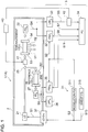
- FIG. 1 is a schematic configuration diagram of a gas analysis system 1 (1A) according to an embodiment of the present invention.
- FIG. 2 is a schematic configuration diagram of a gas analysis system (1B) according to another embodiment of the present invention.
- FIG. 3 is a diagram of a signal obtained by the phase sensitive detector 32 depicted in FIGs. 1 and 2 .
- FIG. 4 is a diagram showing a signal (noise level) obtained in a non-input state by the phase sensitive detector 32 depicted in FIGs. 1 and 2 .
- the gas analysis system 1 (1A, 1B) includes a laser light source 21, a photodetector 22, a gas analysis apparatus 3, a variable light attenuator 41, a transmitted-light amount detector 42, and an attenuation amount controller 43.
- the laser light source 21, the photodetector 22, and the variable light attenuator 41 are housed in a vessel 2, for instance, which is purged with inert gas (e.g. nitrogen gas).
- inert gas e.g. nitrogen gas
- the laser light source 21 emits laser light to be transmitted through an analysis target gas.
- the laser light source 21 comprises a laser diode (LD).
- LD laser diode
- the laser light source 21 is not limited to this and may comprise a quantum-cascade laser, for instance.
- the photodetector 22 outputs signals corresponding to the emission intensity of received laser light, and receives laser light having transmitted through an analysis target gas.
- the photodetector 22 comprises a photo diode (PD S ).
- the photo diode (PD S ) receives laser light having transmitted through an analysis target gas, and outputs a signal corresponding to the intensity of the laser light.
- the photodetector 22 has a high sensitivity to output a signal corresponding to the intensity, and is capable of detecting laser light having a low emission intensity by adjusting the gain.
- the gas analysis apparatus 3 is for analyzing an analysis target gas on the basis of a signal outputted from the photodetector 22.
- the gas analysis apparatus 3 obtains an absorption spectrum of infrared light having a specific wavelength by an analysis target gas from an emission intensity signal of laser light obtained by the photodetector 22, and calculates gas concentration from the absorption spectrum.
- the gas analysis apparatus 3 includes a modulation part 31, a phase sensitive detector 32, a DC component detector 33, and a personal computer (PC) 34.
- the modulation part 31 applies modulation of different frequencies to laser emission wavelengths emitted from the laser light source 21, and outputs a reference signal synchronized with each modulation.
- the modulation part 31 includes a first function generator (modulation component generator, or modulation FG) 311.
- the first function generator 311 outputs a modulation signal S2 for applying modulation to the laser emission wavelength of the laser light source 21 to a light source driver 37, and outputs a reference signal S2 synchronized with the signal to the phase sensitive detector 32.
- the output signal from the phase sensitive detector 32 has an apparent peak, and the level of the output signal (peak height) is in proportion to the absorption amount of laser light, whereby it is possible to obtain the gas concentration of the analysis target gas.
- the signal level obtained in a laser-light input state is clearly different from the signal level (noise level) that can be obtained while the phase sensitive detector 32 is in a non-input state, and thus the signal level obtained in a laser-light input state is sufficiently distinguishable from the signal at the noise level.
- the level of the output signal from the phase sensitive detector 32 and the signal level obtained in a non-input state have an S/N ratio of 10 or more, and the signal level obtained in a laser-light input state is sufficiently distinguishable from the signal at the noise level.
- the phase sensitive detector 32 includes a lock-in amplifier (PSD S ) which detects the absorption amount of laser light by oxygen molecules contained in the analysis target gas on the basis of the reference signal S2 from the first function generator 311 and the light-receiving signal S4 from the photodetector 22.
- PSD S lock-in amplifier
- the DC component detector 33 includes a low-pass filter (LPF S ) which detects a DC component (which corresponds to the transmission factor of laser light) in the light receiving signal S4 of the photodetector 22.
- the low-pass filter (LPF S ) outputs a DC component signal S5, obtained by excluding an AC component such as a modulation component and a noise component from the light-receiving signal S4, to the personal computer (PC) 34 that serves as an analysis part.
- PC personal computer
- the personal computer (PC) 34 includes a computation part (not depicted) which calculates an oxygen concentration and a solid particle concentration contained in the analysis target gas on the basis of signals from the phase sensitive detector 32 and the DC component detector 33, and a display device (not depicted) which displays each concentration value calculated by the computation part on a screen in numerical terms or as a graph.
- the concentration of gas can be obtained by dividing the signal obtained by the phase sensitive detector 32 by the signal obtained by the DC component detector 33.
- the gas analysis apparatus 3 further includes a second function generator (wavelength sweep function generator, or sweep FG) 315 which outputs a signal S13 for slowly sweeping the laser emission wavelength for the purpose of measuring an oxygen absorption spectrum.
- a second function generator wavelength sweep function generator, or sweep FG
- variable light attenuator 41 is disposed between the analysis target gas and the laser light source 21.
- a transmitted-light amount detector 42 is for evaluating the transmitted light amount of laser light having transmitted through the analysis target gas, and evaluates the transmitted light amount of the laser light on the basis of a signal outputted from the photodetector 22.
- the attenuation amount controller 43 is for controlling the attenuation amount of the variable light attenuator 41, and controls the attenuation amount of the variable light attenuator 41 on the basis of the transmitted light amount of the laser light evaluated by the transmitted-light amount detector 42.
- the photodetector 22 outputs 8.0V. Accordingly, it is possible to measure an input of 10mW.
- the gain needs to be multiplied by a hundred times (8.0 ⁇ 10 4 V/W) to output 8.0V to ensure the S/N. If laser light of 10mW is input in this case, the photodetector outputs 800V in a linear output but the output limit of the photodetector 22 is limited to 10V, and thus the output of the photodetector 22 is saturated, which leads to failure of detection of a change in the detection signal accompanying modulation, making the measurement impossible.
- the above configuration prevents such failure by adjusting the attenuation amount of the variable light attenuator 41.
- adjusting the gain would change the characteristics of the photodetector 22 and affect the time constant of detection, which may require another standard curve and calibration. Thus, changing the gain during measurement should be avoided (the gain should be constant).
- the laser light source 21 has a characteristic that changing a current value leads to displacement of the wavelength of the laser light.
- the output amount of the laser light source 21 should not be changed during measurement.
- variable light attenuator 41 provided between the analysis target gas and the laser light source 21 and controlled suitably, it is possible to analyze the analysis target gas whether the amount of soot and dust is great or small, without changing the gain of the photodetector 22 or the output of the laser light source 21.
- the attenuation amount controller 43 which controls the attenuation amount of the variable light attenuator 41 on the basis of the transmitted light amount of laser light evaluated by the transmitted-light amount detector 42, and thus it is possible to analyze the analysis target gas even when the concentration of soot and dust contained in the analysis target gas is high, and also it is possible to analyze the analysis target gas even when the concentration of soot and dust contained in the analysis target gas becomes low. Specifically, by increasing the sensitivity of the photodetector 22, it is possible to analyze the analysis target gas even when the concentration of soot and dust is high.
- the photodetector 22 outputs as a signal the output voltage which is in proportion to the emission intensity of the received laser light, and the transmitted-light amount detector 42 evaluates the transmitted light amount of laser light having transmitted through the analysis target gas on the basis of the output voltage outputted from the photodetector 22.
- the photodetector 22 comprises a photo diode (PD S ) which outputs as a signal the output voltage which is in proportion to the emission intensity of the received laser light, and the transmitted-light amount detector 42 evaluates the transmitted light amount of laser light having transmitted through the analysis target gas on the basis of the output voltage outputted from the photo diode (PD S ).
- PD S photo diode
- the transmitted-light amount detector 42 evaluates the transmitted light amount of laser light having transmitted through the analysis target gas on the basis of the output voltage outputted from the photodetector 22, and thereby it is possible to simplify evaluation of the transmitted light amount of laser light.
- a low-pass filter (LPF S ) for removing a noise component is further provided between the photodetector 22 and the transmitted-light amount detector 42.
- the low-pass filter removes a noise component, and thus it is possible to evaluate the transmitted light amount of laser light appropriately with the transmitted-light amount detector 42 and to analyze the analysis target gas accurately.
- a measurement cell 5 for extracting the analysis target gas is disposed between the variable light attenuator 41 and the photodetector 22.
- An input window 53 is disposed on an end of the measurement cell 5, and an output window 54 is disposed on the other end of the measurement cell 5.
- the light distributor 25 and the variable light attenuator 41 described above are disposed in front of the input window 53, and the laser light source 21 is disposed in front of the light distributor 25 and the variable light attenuator 41 (herein, "front” means the upstream side with respect to the emitting direction of laser light).
- the laser light emitted from the laser light source 21 passes through the light distributor 25 to become a partially transmitted light, and is attenuated by the variable light attenuator 41, before being input to the measurement cell 5 via the input window 53.
- the emitting operation of the laser light source 21 is controlled by the control signal S1 from the light source driver 37.
- the light source driver 37 includes a control circuit for matching the emission wavelength of the laser light source 21 with one of the absorption wavelengths specific to oxygen molecules (O 2 ).
- the above described photodetector 22 is disposed behind the output window 54.
- the photodetector 22 receives laser light having passed through the measurement cell 5, and outputs a light receiving signal S4 corresponding to the intensity of the laser light to the phase sensitive detector 32 and the DC component detector 33.
- "behind” means the downstream side with respect to the emitting direction of the laser light.
- the light distributor 25, the reference cell 26, and a photodetector (standard photodetector) 27 are further provided.
- the light distributor 25 is for distributing a part of laser light emitted from the laser light source 21, and is disposed between the laser light source 21 and the variable light attenuator 41.
- the light distributor 25 comprises a beam splitter (not depicted), for instance.
- a mirror (not depicted) is disposed in the vicinity of the beam splitter, and a part of laser light divided by the beam splitter is reflected by the mirror to be input into the reference cell 26.
- the reference cell 26 contains a predetermined amount of reference gas, and is configured to let through a part of laser light distributed by the light distributor 25.
- a part of laser light enters the reference cell 26 through a window 261, and after passing through the reference cell 26, exits from the reference cell 26 through a window 262.
- a part of laser light that has passed through the reference cell 26 is received by the photodetector 27.
- the photodetector 27 outputs standard signals corresponding to the emission intensity of received laser light, and receives a part of laser light having transmitted through the reference cell.
- the photodetector 27 comprises a photo diode (PD R ).
- the photo diode (PD R ) receives laser light having transmitted through the analysis target gas, and outputs a signal corresponding to the intensity of the laser light.
- the gas analysis apparatus 3 further includes a phase sensitive detector 35 and a DC component detector 36.
- the first function generator (modulation component generator (FG)) 311 outputs, to the phase sensitive detector 35, a reference signal S2 synchronized with the modulation signal S2 for applying modulation to the laser emission wavelength of the laser light source 21.
- the phase sensitive detector 35 includes a lock-in amplifier (PSD R ) which detects the absorption amount of laser light by oxygen molecules contained in the reference gas from the reference signal S2 from the first function generator 311 and the light-receiving signal S6 from the photodetector 27.
- the lock-in amplifier (PSD R ) outputs, to the personal computer (PC) 34, a signal S11 which represents the intensity of a component that synchronizes with the second harmonic of the reference signal (first modulation signal) from the AC component of the light-receiving signal S6.
- the DC component detector 36 includes a low-pass filter (LPF R ) which detects a DC component (which corresponds to the transmission factor of laser light) from the light receiving signal S6 of the photodetector 27.
- the low-pass filter (LPF R ) outputs a DC component signal S7, obtained by excluding an AC components such as a modulation component and a noise component from the light-receiving signal S6, to a personal computer (PC) 34 that serves as an analysis part.
- PC personal computer
- the personal computer calibrates the analysis result of the analysis target gas on the basis of the signal outputted by the photodetector 27.
- the analysis result of the analysis target gas is calibrated on the basis of the standard signal outputted by the photodetector 27, and thus the analysis result of the analysis target gas analyzed on the basis of the emission intensity of the laser light attenuated by the variable light attenuator 41 can be compared with.
- the light distributor 25 is disposed between the laser light source 21 and the variable light attenuator 41, which is upstream of the variable light attenuator 41, and thus laser light before being attenuated by the variable light attenuator 41 is distributed to the reference cell 26.
- the reference cell 26 is analyzed by laser light having an appropriate emission intensity, and thus the analysis target gas is analyzed by laser light adjusted to an emission intensity suited for the concentration of soot and dust contained in the analysis target gas. Accordingly, the reference cell 26 can be analyzed with laser light having a suitable emission intensity which is higher than the emission intensity of laser light adjusted to an emission intensity suitable for the concentration of soot and dust.
- an insertion measurement probe 6 to be inserted into a measuring target site (which exists outside the vessel 2 of the gas analysis system 1 B) where the analysis target gas exists, a first optical fiber 61 inserted through the insertion measurement probe 6 to guide laser light to the measurement target site from the variable light attenuator 41 in the vessel 2, and a second optical fiber 62, inserted through the insertion measurement probe 6, to guide the laser light from the measurement target site to the photodetector 22 inside the vessel 2.
- the insertion measurement probe 6 can be inserted into the measurement target site where the analysis target gas exists. Accordingly, it is possible to analyze the analysis target gas which exists in the target measurement site into which the insertion measurement probe can be easily inserted.
- the insertion measurement probe 6 includes a measurement part 63 disposed in a light path between an output surface of the first optical fiber 61 from which the laser light is emitted and an input surface of the second optical fiber 62 into which the laser light enters.
- the analysis target gas exists at the measurement part 63.
- An optical system may be disposed in the light path between the output surface of the first optical fiber 61 and the input surface of the second optical fiber 62, to guide laser light emitted from the output surface of the first optical fiber 61 to the input surface of the second optical fiber 62 via the measurement part 63.
- the analysis target gas exists in the measurement part 63 disposed in the light path between the output surface of the first optical fiber 61 from which the laser light is emitted and the input surface of the second optical fiber 62 into which the laser light enters, and thus it is possible to analyze the analysis target gas reliably. Further, it is possible to reduce the length of the light path, and thus it is possible to obtain data in a local range through which the laser light transmits, even when the concentration of soot and dust is high and the analysis target gas cannot be analyzed as a whole.
- FIG. 5 is a flowchart showing a control of the attenuation amount controller 43 depicted in FIGs. 1 and 2 .
- the attenuation amount controller 43 performs a control so as to increase the attenuation amount (step S24) if the intensity of laser light evaluated by the transmitted-light amount detector 42 is greater than a threshold (step S22: NO), or reduce the attenuation amount (step S23) if the intensity of laser light does not exceed the threshold (step S22: NO).
- the attenuation amount is increased if the intensity of laser light evaluated by the transmitted-light amount detector 42 is greater than a threshold, and the attenuation amount is reduced if the intensity of the laser light is not greater than the threshold, which makes it possible to maintain the emission intensity of laser light having transmitted through the analysis target gas appropriately. Accordingly, it is possible to analyze the analysis target gas even when the concentration of soot and dust contained in the analysis target gas is high, and also it is possible to analyze the analysis target gas accurately even when the concentration of soot and dust contained in the analysis target gas becomes low.
- the threshold is set to a value not less than 80% of the maximum output value of the photodetector 22.
- the threshold is set to a value not less than 80% of the maximum output value of the photodetector 22, and thus the attenuation amount is reduced if the intensity of laser light is less than 80% of the maximum output value of the photodetector 22. Accordingly, light of at least 80% of the maximum output value enters the photodetector 22, and thus it is possible to maintain a high detection accuracy.
- FIG. 6 is a conceptual diagram of a boiler 7 provided with a gas analysis system according to an embodiment.
- the boiler 7 includes a furnace 700 and at least one burner 710 for combusting fuel in the furnace 700.
- the boiler 7 may be a powdered-coal boiler configured to be capable of combusting powdered coal.
- the boiler 7 includes a gas analysis system 1 having the above configuration, whereby it is possible to analyze combustion gas inside the furnace 700 with the gas analysis system 1.
- the laser light source 21 of the gas analysis system 1 is disposed so that laser light transmits through combustion gas, which is the analysis target gas, at an observation point P disposed in the furnace 700 of the boiler 7.
- the gas analysis system 1 is configured to analyze combustion gas inside the furnace 700 at the downstream side of the burner 710.
- the observation point P is disposed on the downstream side of the burner 710 inside the furnace 700, and the laser light source 21 is disposed so that laser light transmits through the observation point P.
- soot and dust e.g. concentration of soot and dust coming from powdered-coal fuel
- concentration of soot and dust changes considerably in response to a change in the operational condition of the boiler 7 (e.g. a change in the type of fuel, increase or decrease in the efficiency).
- the boiler 7 further includes an additional air supplying part 720 for supplying additional combustion air into the furnace 700 at the downstream side of the burner 710.
- the gas analysis system 1 is configured to analyze combustion gas inside the furnace 700, at the downstream side of the burner 710 and at the upstream side of the additional air supplying part 720.
- the laser light source 21 is disposed so that laser light passes through the observation point P on the downstream side of the burner 710 and the upstream side of the additional air supplying part 720 inside the furnace 700.
- a reduction combustion region 730 is formed on the downstream side of the burner 710 and the upstream side of the additional air supplying part 720.
- the composition of combustion gas in the reduction combustion region 730 is an important piece of information for appropriate operation control for the boiler 7.
- the concentration of soot and dust in the reduction combustion region 730 is high, and thus it is not easy to analyze combustion gas in the reduction combustion region 730.
- the gas analysis system 1 of the above configuration includes the attenuation amount controller 43 for controlling the attenuation amount of the variable light attenuator 41 on the basis of the transmitted light amount of laser light evaluated by the transmitted-light amount detector 42, and thus it is possible to analyze combustion gas with high accuracy in the reduction combustion region 730 having a high concentration of soot and dust.
- the attenuation amount controller 43 for controlling the attenuation amount of the variable light attenuator 41 on the basis of the transmitted light amount of laser light evaluated by the transmitted-light amount detector 42, and thus it is possible to analyze combustion gas with high accuracy in the reduction combustion region 730 having a high concentration of soot and dust.
- laser light is input into the boiler 7 to measure the concentration of oxygen and the concentration of soot and dust in combustion exhaust gas directly, to verify whether it is possible to perform contact-free measurement directly without sampling the concentration of gas and the concentration of solid particles in the combustion furnace and the flue portion.
- two measurement windows 753, 754 are disposed on a side wall of the furnace 700 of the boiler 7.
- the measurement windows 753, 754 are disposed below the additional air supplying part 720, at a position where laser light can be directly projected into the furnace 700.
- the laser light source 21 is disposed so as to face the measurement window 753.
- the light-receiving part 22 is disposed so as to face the measurement window 754.
- the laser light source 21 is configured to receive the modulation signals S2, S3 outputted from the modulation part 31 inside a boiler control chamber 8. Further, the light-receiving part 22 outputs the light receiving signal to the analysis part 38 of the boiler control chamber. Further, the modulation part 31 outputs the modulation signals S2, S3 to the analysis part 38.
- laser light emitted from the laser light source 21 transmits through combustion gas, which is an analysis target gas, at the observation point P disposed inside the furnace 700 inside the boiler 7, and thereby it is possible to analyze combustion gas disposed at the observation point P disposed inside the furnace 700 of the boiler 7.
- the observation point P is disposed between the reduction combustion region 730 and a combustion completion region 740.
- laser light emitted from the laser light source 21 transmits through combustion gas, which is the analysis target gas, at the observation point P disposed between the reduction combustion region 730 and the combustion completion region 740, it is possible to analyze combustion gas disposed between the reduction combustion region 730 and the combustion completion region 740.
- the gas analysis apparatus 3 analyzes the oxygen concentration, the carbon monoxide concentration, and the gas temperature of combustion gas, which is the analysis target gas, at the observation point P.
- the gas analysis apparatus 3 analyzes the oxygen concentration, the carbon monoxide concentration, and the gas temperature of combustion gas, which is an analysis target gas, at the observation point P, and thereby it is possible to determine the operational state of the boiler 7.
- an increase or decrease value is determined for primary air, secondary air, the fuel supply amount, or the supply ratio of primary air to secondary air, to achieve the optimum combustion region, on the basis of the concentration distribution of oxygen and carbon monoxide, and the temperature distribution, in the reduction combustion region, and is transmitted to the boiler control part (not depicted).
- the optimum combustion region refers to a region where the combustion state is such that NOx decreases and the combustion efficiency improves.
Landscapes
- Physics & Mathematics (AREA)
- Chemical & Material Sciences (AREA)
- Engineering & Computer Science (AREA)
- Health & Medical Sciences (AREA)
- Life Sciences & Earth Sciences (AREA)
- General Physics & Mathematics (AREA)
- Pathology (AREA)
- Immunology (AREA)
- Analytical Chemistry (AREA)
- Biochemistry (AREA)
- General Health & Medical Sciences (AREA)
- Spectroscopy & Molecular Physics (AREA)
- Medicinal Chemistry (AREA)
- Food Science & Technology (AREA)
- Optics & Photonics (AREA)
- Combustion & Propulsion (AREA)
- Mechanical Engineering (AREA)
- General Engineering & Computer Science (AREA)
- Investigating Or Analysing Materials By Optical Means (AREA)
- Optical Measuring Cells (AREA)
Abstract
Description
- The present disclosure relates to a gas analysis system and a boiler.
- In recent years, a laser-type optical chemical-species sensor has been developed to deal with problems related to extraction measurement techniques. The laser-type measurement techniques can perform measurement "on site", and also has another advantage, which is a high-speed feedback suitable for a dynamic process control. The tunable diode laser absorption spectroscopy (TDLAS) is a particularly promising technique for measuring the composition and temperature of combustion gas and other combustion parameters. TDLAS is typically performed by a diode laser which operates in the near-infrared spectral region and the mid-infrared spectral region. Suitable lasers have been developed extensively to be used in the long-distance telecommunication industry, and are easily accessible for the TDLAS usage. Various TDLAS techniques have been developed, which are more or less suitable for detection and control of a combustion process. Commonly known techniques include the wavelength modulation spectroscopy, the frequency modulation spectroscopy, and the direct absorption spectroscopy. In each of the above techniques, light is conducted through a combustion process chamber, and is absorbed in a specific spectral band that uniquely corresponds to a gas that exists in the process chamber, or a combustion chamber, before being received by a detector. It is based on a pre-obtained relationship between the amount and the characteristics of laser light. The absorption spectrum received by the detector is used to obtain the amount of a gas chemical species to be analyzed, and a combustion parameter (e.g. temperature) related to the amount.
- Furthermore, generally, TDLAS is performed by transmitting laser light that has passed through a target environment, and then detecting absorption of the laser light at a specific wavelength due to a target gas such as carbon monoxide and oxygen. The spectrum analysis on the detected light makes it possible to identify the type and amount of gas along a laser path. The laser absorption spectroscopy is contact-free, and thus is suitable for use in a severe environment, such as a combustion section in a coal combustion power plant, and a flammable or toxic environment where other types of probe cannot be used. While such an environment may cause extreme attenuation (typically, light loss over 90%), using laser light makes it possible to achieve a high luminance required to realize transmission which can be detected even under such attenuation. To bear the harsh condition of a target usage more suitably, laser light may be sent into a target environment through protected optical fiber (e.g. Patent Document 1).
- Further,
Patent Document 2 discloses a gas concentration measuring apparatus that uses the laser absorption spectroscopy, which includes a light source part capable of adjusting laser oscillation wavelengths to a plurality of absorption wavelengths inherent to a gas to be measured, a modulation part for applying modulation to the laser oscillation wavelengths emitted from the light source part and outputting a reference signal synchronized to the modulation, a light receiving part for receiving the laser light having passed through the target gas in a measuring region and outputting signals corresponding to the intensities of the received beams, a phase sensitive detection part for detecting the component synchronized to the modulation signal added to the laser light or the higher harmonic component from the signal of the light receiving part on the basis of the reference signal outputted from the modulation part and outputting the same, and an analyzing part for calculating the concentration of the target gas in the measuring region and the concentration of solid particles on the basis of the signal outputted from the phase sensitive detection part and the signal from the light receiving part. -
Patent Document 3 discloses a laser type gas analyzer for receiving a laser light in a mid-infrared region including an optical absorption spectrum of a measurement target gas, and calculating gas concentration from an amount of change of a signal component affected by optical absorption by the measurement target gas. The laser type gas analyzer includes: a near-infrared laser emission part for emitting a laser light of a near-infrared region including an optical absorption spectrum of water being present in an inside of a flue without including the optical absorption spectrum of the measurement target gas; an optical system such as a lens for irradiating the inside of the flue with a near-infrared laser light; a lens and a near-infrared photodetector for receiving the near-infrared laser light and outputting it as an electric signal; a water concentration calculation part for extracting a signal component affected by optical absorption by water being present in the inside of the flue from the electric signal and calculating water concentration from the amount of change therein; and a gas concentration correction part for correcting a concentration measurement value of the measurement target gas calculated by using mid-infrared laser light on the basis of the water concentration. -
- Patent Document 1:
JP2006-522938A - Patent Document 2:
JP4467674B - Patent Document 3:
JP2013-117517A - In the laser absorption spectroscopy disclosed in
Patent Document 1, if a combustion gas to be analyzed contains a high concentration of soot and dust, it leads to not only attenuation of the laser light by the analysis target gas but also to remarkable attenuation of the laser intensity (typically, light loss over 99%) from an influence of diffusion or the like due to soot and dust, which makes it difficult to analyze the analysis target gas accurately. - Further, also with the gas concentration measuring apparatus disclosed in
Patent Document 2, if a combustion gas to be analyzed contains a high concentration of soot and dust, it leads to not only attenuation of the laser light by the analysis target gas but also to remarkable attenuation of the laser intensity (typically, light loss over 99%) from an influence of diffusion or the like due to soot and dust, which makes it difficult to analyze the analysis target gas accurately. - Furthermore, if a laser-type gas analysis meter is designed to have a light-receiving sensitiveness suited for measurement in an environment where the laser intensity is attenuated remarkably (typically, light loss over 99%) from an influence of diffusion or the like due to soot and dust, it is difficult to analyze an analysis target gas accurately when the concentration of soot and dust becomes low and the emission intensity of laser light gets high, for the light-receiving element (photodetector) becomes saturated.
- In view of the above, an object of at least one embodiment of the present invention is to provide a gas analysis system and a boiler including the same, whereby it is possible to analyze an analysis target gas even when the analysis target gas contains a high concentration of soot and dust, and whereby it is also possible to analyze an analysis target gas accurately even when the concentration of soot and dust contained in the analysis target gas becomes low.
-
- (1) A gas analysis system according to at least one embodiment of the present invention comprises: a laser light source for emitting a laser light to be transmitted through an analysis target gas; a photodetector configured to receive the laser light transmitted through the analysis target gas, for outputting a signal corresponding to an emission intensity of the received laser light; a gas analysis apparatus for analyzing the analysis target gas on the basis of the signal outputted from the photodetector; a variable light attenuator disposed between the analysis target gas and the laser light source; a transmitted-light amount detector configured to evaluate a transmitted light amount of the laser light transmitted through the analysis target gas on the basis of the signal outputted from the photodetector; and an attenuation amount controller configured to control an attenuation amount of the variable light attenuator on the basis of the transmitted light amount of the laser light evaluated by the transmitted-light amount detector.
With this configuration (1), provided is the attenuation amount controller which controls the attenuation amount of the variable light attenuator on the basis of the transmitted light amount of laser light evaluated by the transmitted-light amount detector, and thus it is possible to analyze the analysis target gas even when the concentration of soot and dust contained in the analysis target gas is high, and also it is possible to analyze the analysis target gas accurately even when the concentration of soot and dust contained in the analysis target gas becomes low. Specifically, with the photodetector having a high sensitiveness, it is possible to analyze the analysis target gas even when the concentration of soot and dust is high. Furthermore, even when the concentration of soot and dust contained in the analysis target gas becomes low, it is possible to analyze the analysis target gas accurately with the photodetector still having a high sensitiveness by increasing the attenuation amount of the variable light attenuator. - (2) In some embodiments, in the above configuration (1), the photodetector is configured to output an output voltage in proportion to the emission intensity of the received laser light as the signal, and the transmitted-light amount detector is configured to evaluate the transmitted light amount of the laser light transmitted through the analysis target gas on the basis of the output voltage outputted from the photodetector.
With the above configuration (2), while the photodetector outputs as a signal the output voltage which is in proportion to the emission intensity of the received laser light, the transmitted-light amount detector evaluates the transmitted light amount of laser light having transmitted through the analysis target gas on the basis of the output voltage outputted from the photodetector, and thereby it is possible to simplify evaluation of the transmitted light amount of laser light. - (3) In some embodiments, in the above configuration (1) or (2), the attenuation amount controller is configured to increase the attenuation amount if an intensity of the laser light evaluated by the transmitted-light amount detector is greater than a threshold, and to reduce the attenuation amount if the intensity of the laser light is not greater than the threshold.
With the above configuration (3), the attenuation amount is increased if the intensity of laser light evaluated by the transmitted-light amount detector is greater than a threshold, and the attenuation amount is reduced if the intensity of the laser light is not greater than the threshold, which makes it possible to maintain the emission intensity of laser light having transmitted through the analysis target gas appropriately. Accordingly, it is possible to analyze the analysis target gas even when the concentration of soot and dust contained in the analysis target gas is high, and also it is possible to analyze the analysis target gas accurately even when the concentration of soot and dust contained in the analysis target gas becomes low. - (4) In some embodiments, in the above configuration (3), the threshold is set to a value which is at least 80% of a maximum output value of the photodetector.
With the above configuration (4), the threshold is set to a value not less than 80% of the maximum output value of the photodetector, and thus the attenuation amount is reduced if the intensity of laser light is less than 80% of the maximum output value of the photodetector. Accordingly, light of at least 80% of the maximum output value enters the photodetector, and thus it is possible to maintain a high detection accuracy. - (5) In some embodiments, in any one of the above configurations (1) to (4), the laser light source is disposed so that the laser light transmits through a combustion gas which serves as the analysis target gas, at an observation point disposed inside a furnace of a boiler.
With the above configuration (5), laser light emitted from the laser light source transmits through combustion gas, which is an analysis target gas, at the observation point disposed inside the furnace of the boiler, and thereby it is possible to analyze combustion gas disposed at the observation point disposed inside the furnace. Specifically, by increasing the sensitivity of the photodetector, it is possible to analyze combustion gas even when a high concentration of soot and dust is contained in the combustion gas at the observation point. Furthermore, even when the concentration of soot and dust contained in the combustion gas becomes low, it is possible to analyze the combustion gas with the photodetector still having a high sensitiveness, by increasing the attenuation amount of the variable light attenuator. - (6) In some embodiments, in the above configuration (5), the observation point is disposed between a burner of the boiler and an additional air supplying part, inside the furnace.
With the above configuration (6), laser light emitted from the laser light source transmits through combustion gas, which is the analysis target gas, at the observation point disposed between the burner and the additional air supplying part, and thereby it is possible to analyze combustion gas in the reduction combustion region disposed between the burner and the additional air supplying part. - (7) In some embodiments, in the above configuration (5) or (6), the gas analysis apparatus is configured to analyze an oxygen concentration, a carbon monoxide concentration, and a gas temperature of the combustion gas serving as the analysis target gas, at the observation point.
With the above configuration (7), the gas analysis apparatus analyzes the oxygen concentration, the carbon monoxide concentration, and the gas temperature of combustion gas, which is an analysis target gas, at the observation point, and thereby it is possible to determine the operational state of the boiler. - (8) In some embodiments, in any one of the above configurations (1) to (7), the gas analysis system further comprises: a light distributor, disposed between the laser light source and the variable light attenuator, for distributing a part of the laser light emitted from the laser light source; a reference cell which contains a predetermined amount of the analysis target gas and through which the part of the laser light distributed by the light distributor transmits; and a standard photo detector configured to receive the part of the laser light transmitted through the reference cell, for outputting a standard signal corresponding to an emission intensity of the part of the received laser light. The gas analysis apparatus is configured to calibrate an analysis result of the analysis target gas on the basis of the standard signal outputted by the standard photodetector.
With the above configuration (8), the analysis result of the analysis target gas is calibrated on the basis of the standard signal outputted by the standard photodetector, and then the analysis result of the analysis target gas analyzed on the basis of the emission intensity of the laser light attenuated by the variable light attenuator can be compared with. Further, the light distributor is disposed between the laser light source and the variable light attenuator, which is upstream of the variable light attenuator, and thus laser light before being attenuated by the variable light attenuator is distributed to the reference cell. Accordingly, the reference cell is analyzed by laser light having an appropriate emission intensity, and thus the analysis target gas is analyzed by laser light adjusted to an emission intensity suitable for the concentration of soot and dust contained in the analysis target gas. Accordingly, the reference cell can be analyzed with laser light having a suitable emission intensity which is higher than the emission intensity of laser light adjusted to an emission intensity suitable for the concentration of soot and dust. - (9) In some embodiments, in any one of the above configurations (1) to (8), the gas analysis system further comprises a measurement cell, disposed between the variable light attenuator and the photo detector, for extracting the analysis target gas.
With the above configuration (9), it is possible to analyze the analysis target gas even when the analysis target gas extracted by the measurement cell contains a high concentration of soot and dust, and also it is possible to analyze the analysis target gas accurately even when the concentration of soot and dust contained in the analysis target gas becomes low. - (10) In some embodiments, in any one of the above configurations (1) to (8), the gas analysis system further comprises: an insertion measurement probe to be inserted into a measurement target site where the analysis target gas exists; a first optical fiber inserted through the insertion measurement probe, for guiding the laser light from the variable light attenuator to the measurement target site; and a second optical fiber inserted through the insertion measurement probe, for guiding the laser light from the measurement target site to the photo detector.
With the above configuration (10), the insertion measurement probe can be inserted into the measurement target site where the analysis target gas exists. Accordingly, it is possible to analyze the analysis target gas which exists in the target measurement site into which the insertion measurement probe can be easily inserted. - (11) In some embodiments, in the above configuration (10), the insertion measurement probe has a measurement part disposed in a light path between an output surface of the first optical fiber from which the laser light is emitted and an input surface of the second optical fiber into which the laser light enters, and the analysis target gas exists at the measurement part.
With the above configuration (11), the analysis target gas exists at the measurement part disposed in the light path between the output surface of the first optical fiber from which the laser light is emitted and the input surface of the second optical fiber into which the laser light enters, and thus it is possible to analyze the analysis target gas reliably. Further, it is possible to reduce the length of the light path, and thus it is possible to obtain data in a local range through which the laser light transmits, even when the concentration of soot and dust is high and the analysis target gas cannot be analyzed as a whole. - (12) In some embodiments, in any one of the above configurations (1) to (11), the gas analysis system further comprises a low-pass filter for removing a noise component, disposed between the photo detector and the transmitted-light amount detector.
With the above configuration (12), the low-pass filter removes a noise component, and thus it is possible to analyze the analysis target gas accurately. - (13) A boiler according to at least some embodiments of the present invention comprises: a furnace; a burner for combusting fuel in the furnace; and the gas analysis system according to any one of the above (1) to (12), configured to analyze a combustion gas in the furnace at a downstream side of the burner.
With the above configuration (13), with the gas analysis system according to any one of the above (1) to (12) for analyzing combustion gas in the furnace at the downstream side of the burner, it is possible to analyze combustion gas with high accuracy even if the concentration of soot and dust changes considerably in response to a change in the operational condition of the boiler (e.g. a change in the type of fuel, increase or decrease in the efficiency). - (14) In some embodiments, in the above configuration (13), the boiler further comprises an additional air supplying part for supplying an additional combustion air into the furnace, at the downstream side of the burner. The gas analysis system is configured to analyze the combustion gas at a position downstream of the burner and upstream of the additional air supplying part, inside the furnace.
- With the boiler having the above configuration (14), a reduction combustion region is formed on the downstream side of the burner and the upstream side of the additional air supplying part. The composition of combustion gas in the reduction combustion region is an important piece of information for appropriate operation control for the boiler. However, the concentration of soot and dust in the reduction combustion region is high, and thus it is not easy to analyze combustion gas in the reduction combustion region.
- In this regard, with the above configuration (14), it is possible to perform an accurate analysis on combustion gas in the reduction combustion region where the concentration of soot and dust is high, and thereby to perform an appropriate operation control on the boiler.
- According to at least one embodiment of the present invention, it is possible to provide a gas analysis system whereby it is possible to analyze an analysis target gas even when the analysis target gas contains a high concentration of soot and dust, and whereby it is also possible to analyze an analysis target gas accurately even when the concentration of soot and dust contained in the analysis target gas becomes low.
-
-
FIG. 1 is a schematic configuration diagram of a gas analysis system according to an embodiment of the present invention. -
FIG. 2 is a schematic configuration diagram of a gas analysis system according to an embodiment. -
FIG. 3 is a diagram of a signal obtained by the phase sensitive detector depicted inFIGs. 1 and2 . -
FIG. 4 is a diagram showing a noise level obtained by the phase sensitive detector depicted inFIGs. 1 and2 . -
FIG. 5 is a flowchart showing a control of the attenuation-amount controller depicted inFIGs. 1 and2 . -
FIG. 6 is a conceptual diagram of a boiler provided with a gas analysis system according to an embodiment. - Embodiments of the present invention will now be described in detail with reference to the accompanying drawings. It is intended, however, that unless particularly specified, dimensions, materials, shapes, relative positions and the like of components described in the embodiments shall be interpreted as illustrative only and not intended to limit the scope of the present invention.
- For instance, an expression of relative or absolute arrangement such as "in a direction", "along a direction", "parallel", "orthogonal", "centered", "concentric" and "coaxial" shall not be construed as indicating only the arrangement in a strict literal sense, but also includes a state where the arrangement is relatively displaced by a tolerance, or by an angle or a distance whereby it is possible to achieve the same function.
- Further, for instance, an expression of a shape such as a rectangular shape or a cylindrical shape shall not be construed as only the geometrically strict shape, but also includes a shape with unevenness or chamfered corners within the range in which the same effect can be achieved.
- On the other hand, an expression such as "comprise", "include", "have", "contain" and "constitute" are not intended to be exclusive of other components.
-
FIG. 1 is a schematic configuration diagram of a gas analysis system 1 (1A) according to an embodiment of the present invention.FIG. 2 is a schematic configuration diagram of a gas analysis system (1B) according to another embodiment of the present invention.FIG. 3 is a diagram of a signal obtained by the phasesensitive detector 32 depicted inFIGs. 1 and2 .FIG. 4 is a diagram showing a signal (noise level) obtained in a non-input state by the phasesensitive detector 32 depicted inFIGs. 1 and2 . - As depicted in
FIGs. 1 and2 , the gas analysis system 1 (1A, 1B) according to some embodiments of the present invention includes alaser light source 21, aphotodetector 22, agas analysis apparatus 3, a variablelight attenuator 41, a transmitted-light amount detector 42, and anattenuation amount controller 43. - In the embodiment depicted in
FIGs. 1 and2 , thelaser light source 21, thephotodetector 22, and the variablelight attenuator 41 are housed in avessel 2, for instance, which is purged with inert gas (e.g. nitrogen gas). - The
laser light source 21 emits laser light to be transmitted through an analysis target gas. - In the embodiments depicted in
FIGs. 1 and2 , thelaser light source 21 comprises a laser diode (LD). However, thelaser light source 21 is not limited to this and may comprise a quantum-cascade laser, for instance. - The
photodetector 22 outputs signals corresponding to the emission intensity of received laser light, and receives laser light having transmitted through an analysis target gas. - In the embodiment depicted in
FIGs. 1 and2 , thephotodetector 22 comprises a photo diode (PDS). The photo diode (PDS) receives laser light having transmitted through an analysis target gas, and outputs a signal corresponding to the intensity of the laser light. - In the embodiment depicted in
FIGs. 1 and2 , thephotodetector 22 has a high sensitivity to output a signal corresponding to the intensity, and is capable of detecting laser light having a low emission intensity by adjusting the gain. - The
gas analysis apparatus 3 is for analyzing an analysis target gas on the basis of a signal outputted from thephotodetector 22. - In the embodiments depicted in
FIGs. 1 and2 , thegas analysis apparatus 3 obtains an absorption spectrum of infrared light having a specific wavelength by an analysis target gas from an emission intensity signal of laser light obtained by thephotodetector 22, and calculates gas concentration from the absorption spectrum. - Further, in the embodiments illustrated in
FIGs. 1 and2 , thegas analysis apparatus 3 includes amodulation part 31, a phasesensitive detector 32, aDC component detector 33, and a personal computer (PC) 34. - As depicted in
FIGs. 1 and2 , themodulation part 31 applies modulation of different frequencies to laser emission wavelengths emitted from thelaser light source 21, and outputs a reference signal synchronized with each modulation. Themodulation part 31 includes a first function generator (modulation component generator, or modulation FG) 311. Thefirst function generator 311 outputs a modulation signal S2 for applying modulation to the laser emission wavelength of thelaser light source 21 to alight source driver 37, and outputs a reference signal S2 synchronized with the signal to the phasesensitive detector 32. - As depicted in
FIG. 3 , the output signal from the phasesensitive detector 32 has an apparent peak, and the level of the output signal (peak height) is in proportion to the absorption amount of laser light, whereby it is possible to obtain the gas concentration of the analysis target gas. Furthermore, as depicted inFIG. 4 , the signal level obtained in a laser-light input state is clearly different from the signal level (noise level) that can be obtained while the phasesensitive detector 32 is in a non-input state, and thus the signal level obtained in a laser-light input state is sufficiently distinguishable from the signal at the noise level. For instance, the level of the output signal from the phasesensitive detector 32 and the signal level obtained in a non-input state have an S/N ratio of 10 or more, and the signal level obtained in a laser-light input state is sufficiently distinguishable from the signal at the noise level. - As illustrated in
FIGs. 1 and2 , the phasesensitive detector 32 includes a lock-in amplifier (PSDS) which detects the absorption amount of laser light by oxygen molecules contained in the analysis target gas on the basis of the reference signal S2 from thefirst function generator 311 and the light-receiving signal S4 from thephotodetector 22. - As shown in
FIGs. 1 and2 , theDC component detector 33 includes a low-pass filter (LPFS) which detects a DC component (which corresponds to the transmission factor of laser light) in the light receiving signal S4 of thephotodetector 22. The low-pass filter (LPFS) outputs a DC component signal S5, obtained by excluding an AC component such as a modulation component and a noise component from the light-receiving signal S4, to the personal computer (PC) 34 that serves as an analysis part. - The personal computer (PC) 34 includes a computation part (not depicted) which calculates an oxygen concentration and a solid particle concentration contained in the analysis target gas on the basis of signals from the phase
sensitive detector 32 and theDC component detector 33, and a display device (not depicted) which displays each concentration value calculated by the computation part on a screen in numerical terms or as a graph. - In the embodiments depicted in
FIGs. 1 and2 , the concentration of gas can be obtained by dividing the signal obtained by the phasesensitive detector 32 by the signal obtained by theDC component detector 33. - Further, in the embodiments depicted in
FIGs. 1 and2 , thegas analysis apparatus 3 further includes a second function generator (wavelength sweep function generator, or sweep FG) 315 which outputs a signal S13 for slowly sweeping the laser emission wavelength for the purpose of measuring an oxygen absorption spectrum. - The variable
light attenuator 41 is disposed between the analysis target gas and thelaser light source 21. - A transmitted-
light amount detector 42 is for evaluating the transmitted light amount of laser light having transmitted through the analysis target gas, and evaluates the transmitted light amount of the laser light on the basis of a signal outputted from thephotodetector 22. - The
attenuation amount controller 43 is for controlling the attenuation amount of the variablelight attenuator 41, and controls the attenuation amount of the variablelight attenuator 41 on the basis of the transmitted light amount of the laser light evaluated by the transmitted-light amount detector 42. - For instance, with the above configuration, assuming that the output limit of the
photodetector 22 is 10V, if there is an input of 10mW when the gain of thephotodetector 22 is 8.0×10²V/W, thephotodetector 22 outputs 8.0V. Accordingly, it is possible to measure an input of 10mW. - However, if laser light to be measured is 0.1mW, the gain needs to be multiplied by a hundred times (8.0×10⁴V/W) to output 8.0V to ensure the S/N. If laser light of 10mW is input in this case, the photodetector outputs 800V in a linear output but the output limit of the
photodetector 22 is limited to 10V, and thus the output of thephotodetector 22 is saturated, which leads to failure of detection of a change in the detection signal accompanying modulation, making the measurement impossible. - The above configuration prevents such failure by adjusting the attenuation amount of the variable
light attenuator 41. - While one may consider adjusting the gain of the
photodetector 22, adjusting the gain would change the characteristics of thephotodetector 22 and affect the time constant of detection, which may require another standard curve and calibration. Thus, changing the gain during measurement should be avoided (the gain should be constant). - Further, while one may consider changing the output amount of the
laser light source 21, thelaser light source 21 has a characteristic that changing a current value leads to displacement of the wavelength of the laser light. Thus, in measurement such as gas analysis where the wavelength is specifically targeted, the output amount of thelaser light source 21 should not be changed during measurement. - In this regard, with the variable
light attenuator 41 provided between the analysis target gas and thelaser light source 21 and controlled suitably, it is possible to analyze the analysis target gas whether the amount of soot and dust is great or small, without changing the gain of thephotodetector 22 or the output of thelaser light source 21. - With this configuration, provided is the
attenuation amount controller 43 which controls the attenuation amount of the variablelight attenuator 41 on the basis of the transmitted light amount of laser light evaluated by the transmitted-light amount detector 42, and thus it is possible to analyze the analysis target gas even when the concentration of soot and dust contained in the analysis target gas is high, and also it is possible to analyze the analysis target gas even when the concentration of soot and dust contained in the analysis target gas becomes low. Specifically, by increasing the sensitivity of thephotodetector 22, it is possible to analyze the analysis target gas even when the concentration of soot and dust is high. Furthermore, even when the concentration of soot and dust contained in the analysis target gas becomes low, it is possible to analyze the analysis target gas accurately with thephotodetector 22 still having a high sensitiveness, by increasing the attenuation amount of the variablelight attenuator 41. - Thus, it is possible to analyze the analysis target gas with high accuracy even if the concentration of soot and dust contained in the analysis target gas changes considerably (e.g. in a range of 0 to 15g/m3).
- As depicted in
FIGs. 1 and2 , in some embodiments, thephotodetector 22 outputs as a signal the output voltage which is in proportion to the emission intensity of the received laser light, and the transmitted-light amount detector 42 evaluates the transmitted light amount of laser light having transmitted through the analysis target gas on the basis of the output voltage outputted from thephotodetector 22. - In the embodiments illustrated in
FIGs. 1 and2 , as described above, thephotodetector 22 comprises a photo diode (PDS) which outputs as a signal the output voltage which is in proportion to the emission intensity of the received laser light, and the transmitted-light amount detector 42 evaluates the transmitted light amount of laser light having transmitted through the analysis target gas on the basis of the output voltage outputted from the photo diode (PDS). - With the above configuration, while the
photodetector 22 outputs as a signal the output voltage which is in proportion to the emission intensity of the received laser light, the transmitted-light amount detector 42 evaluates the transmitted light amount of laser light having transmitted through the analysis target gas on the basis of the output voltage outputted from thephotodetector 22, and thereby it is possible to simplify evaluation of the transmitted light amount of laser light. - As depicted in
FIGs. 1 and2 , in some embodiments, a low-pass filter (LPFS) for removing a noise component is further provided between thephotodetector 22 and the transmitted-light amount detector 42. - With the above configuration, the low-pass filter (LPFS) removes a noise component, and thus it is possible to evaluate the transmitted light amount of laser light appropriately with the transmitted-
light amount detector 42 and to analyze the analysis target gas accurately. - As depicted in
FIG. 1 , in some embodiments, ameasurement cell 5 for extracting the analysis target gas is disposed between the variablelight attenuator 41 and thephotodetector 22. - An
input window 53 is disposed on an end of themeasurement cell 5, and anoutput window 54 is disposed on the other end of themeasurement cell 5. - The
light distributor 25 and the variablelight attenuator 41 described above are disposed in front of theinput window 53, and thelaser light source 21 is disposed in front of thelight distributor 25 and the variable light attenuator 41 (herein, "front" means the upstream side with respect to the emitting direction of laser light). The laser light emitted from thelaser light source 21 passes through thelight distributor 25 to become a partially transmitted light, and is attenuated by the variablelight attenuator 41, before being input to themeasurement cell 5 via theinput window 53. The emitting operation of thelaser light source 21 is controlled by the control signal S1 from thelight source driver 37. Thelight source driver 37 includes a control circuit for matching the emission wavelength of thelaser light source 21 with one of the absorption wavelengths specific to oxygen molecules (O2). - The above described
photodetector 22 is disposed behind theoutput window 54. Thephotodetector 22 receives laser light having passed through themeasurement cell 5, and outputs a light receiving signal S4 corresponding to the intensity of the laser light to the phasesensitive detector 32 and theDC component detector 33. Herein, "behind" means the downstream side with respect to the emitting direction of the laser light. - With this configuration, it is possible to analyze the analysis target gas even when the analysis target gas extracted by the
measurement cell 5 contains a high concentration of soot and dust, and it is also possible to analyze the analysis target gas accurately even when the concentration of soot and dust contained in the analysis target gas becomes low. - As depicted in
FIGs. 1 and2 , in some embodiments, thelight distributor 25, thereference cell 26, and a photodetector (standard photodetector) 27 are further provided. - The
light distributor 25 is for distributing a part of laser light emitted from thelaser light source 21, and is disposed between thelaser light source 21 and the variablelight attenuator 41. - In the embodiments depicted in
FIGs. 1 and2 , thelight distributor 25 comprises a beam splitter (not depicted), for instance. A mirror (not depicted) is disposed in the vicinity of the beam splitter, and a part of laser light divided by the beam splitter is reflected by the mirror to be input into thereference cell 26. - The
reference cell 26 contains a predetermined amount of reference gas, and is configured to let through a part of laser light distributed by thelight distributor 25. - In the embodiments depicted in
FIGs. 1 and2 , a part of laser light enters thereference cell 26 through awindow 261, and after passing through thereference cell 26, exits from thereference cell 26 through awindow 262. A part of laser light that has passed through thereference cell 26 is received by thephotodetector 27. - The
photodetector 27 outputs standard signals corresponding to the emission intensity of received laser light, and receives a part of laser light having transmitted through the reference cell. - In the embodiments depicted in
FIGs. 1 and2 , thephotodetector 27 comprises a photo diode (PDR). The photo diode (PDR) receives laser light having transmitted through the analysis target gas, and outputs a signal corresponding to the intensity of the laser light. - In the embodiments illustrated in
FIGs. 1 and2 , thegas analysis apparatus 3 further includes a phasesensitive detector 35 and aDC component detector 36. - In the embodiments depicted in
FIGs. 1 and2 , the first function generator (modulation component generator (FG)) 311 outputs, to the phasesensitive detector 35, a reference signal S2 synchronized with the modulation signal S2 for applying modulation to the laser emission wavelength of thelaser light source 21. - As depicted in
FIGs. 1 and2 , the phasesensitive detector 35 includes a lock-in amplifier (PSDR) which detects the absorption amount of laser light by oxygen molecules contained in the reference gas from the reference signal S2 from thefirst function generator 311 and the light-receiving signal S6 from thephotodetector 27. The lock-in amplifier (PSDR) outputs, to the personal computer (PC) 34, a signal S11 which represents the intensity of a component that synchronizes with the second harmonic of the reference signal (first modulation signal) from the AC component of the light-receiving signal S6. - As shown in
FIGs. 1 and2 , theDC component detector 36 includes a low-pass filter (LPFR) which detects a DC component (which corresponds to the transmission factor of laser light) from the light receiving signal S6 of thephotodetector 27. The low-pass filter (LPFR) outputs a DC component signal S7, obtained by excluding an AC components such as a modulation component and a noise component from the light-receiving signal S6, to a personal computer (PC) 34 that serves as an analysis part. - The personal computer (PC) calibrates the analysis result of the analysis target gas on the basis of the signal outputted by the
photodetector 27. - With the above configuration, the analysis result of the analysis target gas is calibrated on the basis of the standard signal outputted by the
photodetector 27, and thus the analysis result of the analysis target gas analyzed on the basis of the emission intensity of the laser light attenuated by the variablelight attenuator 41 can be compared with. Further, thelight distributor 25 is disposed between thelaser light source 21 and the variablelight attenuator 41, which is upstream of the variablelight attenuator 41, and thus laser light before being attenuated by the variablelight attenuator 41 is distributed to thereference cell 26. Accordingly, thereference cell 26 is analyzed by laser light having an appropriate emission intensity, and thus the analysis target gas is analyzed by laser light adjusted to an emission intensity suited for the concentration of soot and dust contained in the analysis target gas. Accordingly, thereference cell 26 can be analyzed with laser light having a suitable emission intensity which is higher than the emission intensity of laser light adjusted to an emission intensity suitable for the concentration of soot and dust. - As depicted in
FIG. 2 , in some embodiments, further provided are aninsertion measurement probe 6 to be inserted into a measuring target site (which exists outside thevessel 2 of thegas analysis system 1 B) where the analysis target gas exists, a firstoptical fiber 61 inserted through theinsertion measurement probe 6 to guide laser light to the measurement target site from the variablelight attenuator 41 in thevessel 2, and a secondoptical fiber 62, inserted through theinsertion measurement probe 6, to guide the laser light from the measurement target site to thephotodetector 22 inside thevessel 2. - With the above configuration, the
insertion measurement probe 6 can be inserted into the measurement target site where the analysis target gas exists. Accordingly, it is possible to analyze the analysis target gas which exists in the target measurement site into which the insertion measurement probe can be easily inserted. - As depicted in
FIG. 2 , in some embodiments, theinsertion measurement probe 6 includes ameasurement part 63 disposed in a light path between an output surface of the firstoptical fiber 61 from which the laser light is emitted and an input surface of the secondoptical fiber 62 into which the laser light enters. The analysis target gas exists at themeasurement part 63. An optical system may be disposed in the light path between the output surface of the firstoptical fiber 61 and the input surface of the secondoptical fiber 62, to guide laser light emitted from the output surface of the firstoptical fiber 61 to the input surface of the secondoptical fiber 62 via themeasurement part 63. - With the above configuration, the analysis target gas exists in the
measurement part 63 disposed in the light path between the output surface of the firstoptical fiber 61 from which the laser light is emitted and the input surface of the secondoptical fiber 62 into which the laser light enters, and thus it is possible to analyze the analysis target gas reliably. Further, it is possible to reduce the length of the light path, and thus it is possible to obtain data in a local range through which the laser light transmits, even when the concentration of soot and dust is high and the analysis target gas cannot be analyzed as a whole. -
FIG. 5 is a flowchart showing a control of theattenuation amount controller 43 depicted inFIGs. 1 and2 . - As shown in
FIG. 5 , in some embodiments, theattenuation amount controller 43 performs a control so as to increase the attenuation amount (step S24) if the intensity of laser light evaluated by the transmitted-light amount detector 42 is greater than a threshold (step S22: NO), or reduce the attenuation amount (step S23) if the intensity of laser light does not exceed the threshold (step S22: NO). - With this configuration, the attenuation amount is increased if the intensity of laser light evaluated by the transmitted-
light amount detector 42 is greater than a threshold, and the attenuation amount is reduced if the intensity of the laser light is not greater than the threshold, which makes it possible to maintain the emission intensity of laser light having transmitted through the analysis target gas appropriately. Accordingly, it is possible to analyze the analysis target gas even when the concentration of soot and dust contained in the analysis target gas is high, and also it is possible to analyze the analysis target gas accurately even when the concentration of soot and dust contained in the analysis target gas becomes low. - In some embodiments, the threshold is set to a value not less than 80% of the maximum output value of the
photodetector 22. - With this configuration, the threshold is set to a value not less than 80% of the maximum output value of the
photodetector 22, and thus the attenuation amount is reduced if the intensity of laser light is less than 80% of the maximum output value of thephotodetector 22. Accordingly, light of at least 80% of the maximum output value enters thephotodetector 22, and thus it is possible to maintain a high detection accuracy. -
FIG. 6 is a conceptual diagram of aboiler 7 provided with a gas analysis system according to an embodiment. - As shown in
FIG. 6 , in some embodiments, theboiler 7 includes afurnace 700 and at least oneburner 710 for combusting fuel in thefurnace 700. Theboiler 7 may be a powdered-coal boiler configured to be capable of combusting powdered coal. - The
boiler 7 includes agas analysis system 1 having the above configuration, whereby it is possible to analyze combustion gas inside thefurnace 700 with thegas analysis system 1. Thus, thelaser light source 21 of thegas analysis system 1 is disposed so that laser light transmits through combustion gas, which is the analysis target gas, at an observation point P disposed in thefurnace 700 of theboiler 7. - In some embodiments, the
gas analysis system 1 is configured to analyze combustion gas inside thefurnace 700 at the downstream side of theburner 710. Specifically, the observation point P is disposed on the downstream side of theburner 710 inside thefurnace 700, and thelaser light source 21 is disposed so that laser light transmits through the observation point P. - As described above, with the
gas analysis system 1 analyzing combustion gas in the furnace 500 at the downstream side of theburner 710, it is possible to analyze combustion gas with high accuracy even if the concentration of soot and dust (e.g. concentration of soot and dust coming from powdered-coal fuel) changes considerably in response to a change in the operational condition of the boiler 7 (e.g. a change in the type of fuel, increase or decrease in the efficiency). - In an embodiment, the
boiler 7 further includes an additionalair supplying part 720 for supplying additional combustion air into thefurnace 700 at the downstream side of theburner 710. Further, thegas analysis system 1 is configured to analyze combustion gas inside thefurnace 700, at the downstream side of theburner 710 and at the upstream side of the additionalair supplying part 720. Specifically, thelaser light source 21 is disposed so that laser light passes through the observation point P on the downstream side of theburner 710 and the upstream side of the additionalair supplying part 720 inside thefurnace 700. - With the
boiler 7 having the above configuration, areduction combustion region 730 is formed on the downstream side of theburner 710 and the upstream side of the additionalair supplying part 720. The composition of combustion gas in thereduction combustion region 730 is an important piece of information for appropriate operation control for theboiler 7. However, the concentration of soot and dust in thereduction combustion region 730 is high, and thus it is not easy to analyze combustion gas in thereduction combustion region 730. - In this regard, the
gas analysis system 1 of the above configuration includes theattenuation amount controller 43 for controlling the attenuation amount of the variablelight attenuator 41 on the basis of the transmitted light amount of laser light evaluated by the transmitted-light amount detector 42, and thus it is possible to analyze combustion gas with high accuracy in thereduction combustion region 730 having a high concentration of soot and dust. Thus, it is possible to perform an appropriate operation control on theboiler 7 by utilizing an accurate analysis result of combustion gas in thereduction combustion region 730. - In the embodiment depicted in
FIG. 6 , laser light is input into theboiler 7 to measure the concentration of oxygen and the concentration of soot and dust in combustion exhaust gas directly, to verify whether it is possible to perform contact-free measurement directly without sampling the concentration of gas and the concentration of solid particles in the combustion furnace and the flue portion. - In the embodiment depicted in
FIG. 6 , twomeasurement windows furnace 700 of theboiler 7. Themeasurement windows air supplying part 720, at a position where laser light can be directly projected into thefurnace 700. Thelaser light source 21 is disposed so as to face themeasurement window 753. The light-receivingpart 22 is disposed so as to face themeasurement window 754. - The
laser light source 21 is configured to receive the modulation signals S2, S3 outputted from themodulation part 31 inside aboiler control chamber 8. Further, the light-receivingpart 22 outputs the light receiving signal to theanalysis part 38 of the boiler control chamber. Further, themodulation part 31 outputs the modulation signals S2, S3 to theanalysis part 38. - With the above configuration, laser light emitted from the
laser light source 21 transmits through combustion gas, which is an analysis target gas, at the observation point P disposed inside thefurnace 700 inside theboiler 7, and thereby it is possible to analyze combustion gas disposed at the observation point P disposed inside thefurnace 700 of theboiler 7. - As depicted in
FIG. 6 , in some embodiments, the observation point P is disposed between thereduction combustion region 730 and acombustion completion region 740. - With the above configuration, laser light emitted from the
laser light source 21 transmits through combustion gas, which is the analysis target gas, at the observation point P disposed between thereduction combustion region 730 and thecombustion completion region 740, it is possible to analyze combustion gas disposed between thereduction combustion region 730 and thecombustion completion region 740. - In some embodiments, the
gas analysis apparatus 3 analyzes the oxygen concentration, the carbon monoxide concentration, and the gas temperature of combustion gas, which is the analysis target gas, at the observation point P. - With the above configuration, the
gas analysis apparatus 3 analyzes the oxygen concentration, the carbon monoxide concentration, and the gas temperature of combustion gas, which is an analysis target gas, at the observation point P, and thereby it is possible to determine the operational state of theboiler 7. - Further, excessive oxygen is reduced by controlling primary air, secondary air, and fuel supply amount on the basis of the measurement results of the oxygen concentration and the carbon monoxide concentration, and thereby it is possible to improve the generator power generation efficiency and to reduce NOx.
- For instance, an increase or decrease value is determined for primary air, secondary air, the fuel supply amount, or the supply ratio of primary air to secondary air, to achieve the optimum combustion region, on the basis of the concentration distribution of oxygen and carbon monoxide, and the temperature distribution, in the reduction combustion region, and is transmitted to the boiler control part (not depicted). The optimum combustion region refers to a region where the combustion state is such that NOx decreases and the combustion efficiency improves.
- Embodiments of the present invention were described in detail above, but the present invention is not limited thereto, and various amendments and modifications may be implemented.
- For instance, even when the concentration of soot and dust is high at the observation point P of the
boiler 7 and the entire combustion gas cannot be analyzed, it is possible to obtain data in a local range by inserting theinsertion measurement probe 6 with a reduced light path, and thereby it is possible to analyze the oxygen concentration, the carbon monoxide concentration, and the gas temperature of combustion gas. -
- 1 (1 A, 1B) Gas analysis system
- 2 Vessel
- 21 Laser light source
- 22 Photodetector (standard photo detector)
- 25 Light distributor
- 26 Reference cell
- 261, 262 Window
- 27 Photodetector
- 3 Gas analysis apparatus
- 31 Modulation part
- 311 First function generator (modulation component generator)
- 315 Second function generator (wavelength sweep function generator)
- 32 Phase sensitive detector
- 33 DC component detector
- 34 Personal Computer
- 35 Phase sensitive detector
- 36 DC component detector
- 37 Light source driver
- 38 Analysis part
- 41 Variable light attenuator
- 42 Transmitted-light amount detector
- 43 Attenuation amount controller
- 5 Measurement cell
- 51,52 Gas pipe
- 53 Input window
- 54 Output window
- 6 Insertion measurement probe
- 61 First optical fiber
- 62 Second optical fiber
- 63 Measurement part
- 7 Boiler
- 700 Furnace
- 710 Burner
- 730 Reduction combustion region
- 740 Combustion completion region
- 753 Measurement window
- 754 Measurement window
- 8 Boiler control chamber
Claims (14)
- A gas analysis system, comprising:a laser light source for emitting a laser light to be transmitted through an analysis target gas;a photodetector configured to receive the laser light transmitted through the analysis target gas, for outputting a signal corresponding to an emission intensity of the received laser light;a gas analysis apparatus for analyzing the analysis target gas on the basis of the signal outputted from the photodetector;a variable light attenuator disposed between the analysis target gas and the laser light source;a transmitted-light amount detector configured to evaluate a transmitted light amount of the laser light transmitted through the analysis target gas on the basis of the signal outputted from the photodetector; andan attenuation amount controller configured to control an attenuation amount of the variable light attenuator on the basis of the transmitted light amount of the laser light evaluated by the transmitted-light amount detector.
- The gas analysis system according to claim 1,
wherein the photodetector is configured to output an output voltage in proportion to the emission intensity of the received laser light as the signal, and
wherein the transmitted-light amount detector is configured to evaluate the transmitted light amount of the laser light transmitted through the analysis target gas on the basis of the output voltage outputted from the photodetector. - The gas analysis system according to claim 1 or 2,
wherein the attenuation amount controller is configured to increase the attenuation amount if an intensity of the laser light evaluated by the transmitted-light amount detector is greater than a threshold, and to reduce the attenuation amount if the intensity of the laser light is not greater than the threshold. - The gas analysis system according to claim 3, wherein the threshold is set to a value which is at least 80% of a maximum output value of the photodetector.
- The gas analysis system according to any one of claims 1 to 4,
wherein the laser light source is disposed so that the laser light transmits through a combustion gas which serves as the analysis target gas, at an observation point disposed inside a furnace of a boiler. - The gas analysis system according to claim 5, wherein the observation point is disposed between a burner of the boiler and an additional air supplying part, inside the furnace.
- The gas analysis system according to claim 5 or 6, wherein the gas analysis apparatus is configured to analyze an oxygen concentration, a carbon monoxide concentration, and a gas temperature of the combustion gas serving as the analysis target gas, at the observation point.
- The gas analysis system according to any one of claims 1 to 7, further comprising:a light distributor, disposed between the laser light source and the variable light attenuator, for distributing a part of the laser light emitted from the laser light source;a reference cell which contains a predetermined amount of the analysis target gas and through which the part of the laser light distributed by the light distributor transmits; anda standard photo detector configured to receive the part of the laser light transmitted through the reference cell, for outputting a standard signal corresponding to an emission intensity of the part of the received laser light,wherein the gas analysis apparatus is configured to calibrate an analysis result of the analysis target gas on the basis of the standard signal outputted by the standard photodetector.
- The gas analysis system according to any one of claims 1 to 8, further comprising a measurement cell, disposed between the variable light attenuator and the photo detector, for extracting the analysis target gas.
- The gas analysis system according to any one of claims 1 to 8, further comprising:an insertion measurement probe to be inserted into a measurement target site where the analysis target gas exists;a first optical fiber inserted through the insertion measurement probe, for guiding the laser light from the variable light attenuator to the measurement target site; anda second optical fiber inserted through the insertion measurement probe, for guiding the laser light from the measurement target site to the photo detector.
- The gas analysis system according to claim 10,
wherein the insertion measurement probe has a measurement part disposed in a light path between an output surface of the first optical fiber from which the laser light is emitted and an input surface of the second optical fiber into which the laser light enters, and
wherein the analysis target gas exists at the measurement part. - The gas analysis system according to any one of claims 1 to 11, further comprising a low-pass filter for removing a noise component, disposed between the photo detector and the transmitted-light amount detector.
- A boiler, comprising:a furnace;a burner for combusting fuel in the furnace; andthe gas analysis system according to any one of claims 1 to 12, configured to analyze a combustion gas in the furnace at a downstream side of the burner.
- The boiler according to claim 13, further comprising an additional air supplying part for supplying an additional combustion air into the furnace, at the downstream side of the burner,
wherein the gas analysis system is configured to analyze the combustion gas at a position downstream of the burner and upstream of the additional air supplying part, inside the furnace.
Applications Claiming Priority (2)
| Application Number | Priority Date | Filing Date | Title |
|---|---|---|---|
| JP2015071895A JP6473367B2 (en) | 2015-03-31 | 2015-03-31 | Gas analysis system |
| PCT/JP2015/077026 WO2016157573A1 (en) | 2015-03-31 | 2015-09-25 | Gas analysis system and boiler |
Publications (3)
| Publication Number | Publication Date |
|---|---|
| EP3244195A1 true EP3244195A1 (en) | 2017-11-15 |
| EP3244195A4 EP3244195A4 (en) | 2018-09-05 |
| EP3244195B1 EP3244195B1 (en) | 2020-04-29 |
Family
ID=57004888
Family Applications (1)
| Application Number | Title | Priority Date | Filing Date |
|---|---|---|---|
| EP15887715.9A Active EP3244195B1 (en) | 2015-03-31 | 2015-09-25 | Gas analysis system and boiler |
Country Status (4)
| Country | Link |
|---|---|
| US (1) | US10302558B2 (en) |
| EP (1) | EP3244195B1 (en) |
| JP (1) | JP6473367B2 (en) |
| WO (1) | WO2016157573A1 (en) |
Families Citing this family (8)
| Publication number | Priority date | Publication date | Assignee | Title |
|---|---|---|---|---|
| CN110261006B (en) * | 2019-05-17 | 2021-01-01 | 华电电力科学研究院有限公司 | Thermal power generation-based detection method for temperature of flue gas of hearth of power station boiler |
| JP7634483B2 (en) * | 2019-12-17 | 2025-02-21 | 株式会社堀場製作所 | Analytical device and analytical system |
| CN113624705A (en) * | 2020-05-08 | 2021-11-09 | 高利通科技(深圳)有限公司 | Gas measurement system based on differential ultraviolet spectroscopy |
| US12360089B2 (en) * | 2020-06-25 | 2025-07-15 | Shimadzu Corporation | Gas spectroscopic device and gas spectroscopic method |
| WO2022074488A1 (en) * | 2020-10-09 | 2022-04-14 | Onpoint Technologies, Llc | Combustion-zone chemical sensing system and associated method |
| CN114112936A (en) * | 2021-11-25 | 2022-03-01 | 国能国华(北京)电力研究院有限公司 | Near-wall smoke component measuring device and method for boiler water-cooled wall |
| CN114460039B (en) * | 2022-01-07 | 2024-02-02 | 南京科远智慧科技集团股份有限公司 | Emission light power management method for measuring hearth gas of TDLAS pulverized coal boiler |
| CN115015184A (en) * | 2022-07-07 | 2022-09-06 | 中国烟草总公司郑州烟草研究院 | Light transmission method aerosol concentration detection calibration system, calibration method and measurement method |
Family Cites Families (27)
| Publication number | Priority date | Publication date | Assignee | Title |
|---|---|---|---|---|
| US5572031A (en) * | 1994-11-23 | 1996-11-05 | Sri International | Pressure- and temperature-compensating oxygen sensor |
| WO1997025609A1 (en) * | 1996-01-12 | 1997-07-17 | The Regents Of The University Of California | Optical probe for in-situ detection of hydrocarbon concentration |
| JP4467674B2 (en) * | 1999-08-31 | 2010-05-26 | 三菱重工業株式会社 | Gas concentration measuring device |
| AU1751701A (en) | 1999-11-04 | 2001-05-14 | L'air Liquide, Societe Anonyme A Directoire Et Conseil De Surveillance Pour L'etude Et L'exploitation Des Procedes Georges Claude | Method for continuously monitoring chemical species and temperature in hot process gases |
| CN101408458A (en) | 2003-03-31 | 2009-04-15 | 佐勒技术公司 | Method and device for monitoring and controlling combusting course |
| US7352464B2 (en) | 2004-01-05 | 2008-04-01 | Southwest Sciences Incorporated | Oxygen sensor for aircraft fuel inerting systems |
| US7324203B2 (en) | 2005-02-08 | 2008-01-29 | General Electric Company | Method and apparatus for optical detection for multi-phase combustion systems |
| JP4713227B2 (en) * | 2005-06-06 | 2011-06-29 | トヨタ自動車株式会社 | Exhaust gas analyzer and exhaust gas analysis method |
| JP4199766B2 (en) * | 2005-12-16 | 2008-12-17 | トヨタ自動車株式会社 | Exhaust gas analysis method and exhaust gas analyzer |
| JP4227991B2 (en) * | 2005-12-28 | 2009-02-18 | トヨタ自動車株式会社 | Exhaust gas analyzer and exhaust gas analysis method |
| JP4715759B2 (en) * | 2006-04-25 | 2011-07-06 | 株式会社島津製作所 | Moisture meter |
| JP4732277B2 (en) * | 2006-08-23 | 2011-07-27 | トヨタ自動車株式会社 | Gas analyzer and gas analysis method |
| WO2008106056A1 (en) * | 2007-02-26 | 2008-09-04 | Analytical Special Ties, Inc. | Combustion gas analysis |
| US8500442B2 (en) | 2007-02-26 | 2013-08-06 | Yokogawa Corp. Of America | Combustion gas analysis |
| US7653497B2 (en) * | 2007-05-15 | 2010-01-26 | Spectrasensors, Inc. | Energy flow measurement in gas pipelines |
| JP5371268B2 (en) * | 2008-03-14 | 2013-12-18 | 三菱重工業株式会社 | Gas concentration measuring method and apparatus |
| CN101387607B (en) * | 2008-10-08 | 2010-12-08 | 南京顺泰科技有限公司 | Oxygen in situ detecting method and apparatus by infrared laser spectroscopy |
| JP5349996B2 (en) * | 2009-02-10 | 2013-11-20 | 一般財団法人電力中央研究所 | Gas concentration measuring device |
| JP5155913B2 (en) * | 2009-03-18 | 2013-03-06 | トヨタ自動車株式会社 | Exhaust gas analyzer |
| JP2010237106A (en) * | 2009-03-31 | 2010-10-21 | Toyota Motor Corp | Exhaust gas analyzer |
| JP2012225730A (en) * | 2011-04-19 | 2012-11-15 | Shimadzu Corp | Gas concentration measuring apparatus |
| JP6044760B2 (en) | 2011-11-02 | 2016-12-14 | 富士電機株式会社 | Laser gas analyzer |
| US8891085B2 (en) * | 2012-11-02 | 2014-11-18 | Shimadzu Corporation | Gas analyzer |
| US9863887B2 (en) * | 2012-11-15 | 2018-01-09 | Nemor Technologies Ou | Unit and method for optical non-contact oil detection |
| EP2746747A1 (en) * | 2012-12-21 | 2014-06-25 | ABB Research Ltd. | Sensor assembly and method for determining the hydrogen and moisture content of transformer oil |
| KR102197456B1 (en) * | 2014-01-31 | 2020-12-31 | 비아비 솔루션즈 아이엔씨. | An optical filter and spectrometer |
| GB201700905D0 (en) * | 2017-01-19 | 2017-03-08 | Cascade Tech Holdings Ltd | Close-Coupled Analyser |
-
2015
- 2015-03-31 JP JP2015071895A patent/JP6473367B2/en not_active Expired - Fee Related
- 2015-09-25 EP EP15887715.9A patent/EP3244195B1/en active Active
- 2015-09-25 WO PCT/JP2015/077026 patent/WO2016157573A1/en not_active Ceased
- 2015-09-25 US US15/560,744 patent/US10302558B2/en not_active Expired - Fee Related
Also Published As
| Publication number | Publication date |
|---|---|
| EP3244195A4 (en) | 2018-09-05 |
| JP6473367B2 (en) | 2019-02-20 |
| EP3244195B1 (en) | 2020-04-29 |
| JP2016191628A (en) | 2016-11-10 |
| WO2016157573A1 (en) | 2016-10-06 |
| US10302558B2 (en) | 2019-05-28 |
| US20180080869A1 (en) | 2018-03-22 |
Similar Documents
| Publication | Publication Date | Title |
|---|---|---|
| US10302558B2 (en) | Gas analysis system and boiler | |
| US9546902B2 (en) | Method and system for correcting incident light fluctuations in absorption spectroscopy | |
| JP5983779B2 (en) | Gas absorption spectroscopy apparatus and gas absorption spectroscopy method | |
| JP6044760B2 (en) | Laser gas analyzer | |
| JP6128361B2 (en) | Multi-component laser gas analyzer | |
| US20160178517A1 (en) | Apparatus and method of gas analysis using laser light | |
| KR102056794B1 (en) | Alignment System for TDLAS of Simultaneous Measurement of Multicomponent Gas using Micro Optical Passage | |
| US9506807B2 (en) | Optical gas temperature sensor | |
| CN102022193A (en) | Systems and methods for closed loop emissions control | |
| JP2018096974A (en) | Analysis device, analysis device program and analysis method | |
| CN101287976A (en) | Dichroic Gas Spectral Calibration | |
| JP4467674B2 (en) | Gas concentration measuring device | |
| KR100747768B1 (en) | Hazardous Gas Measurement Device Using Wavelength Modulation Method | |
| JP2016191628A5 (en) | ||
| KR101682112B1 (en) | Combustion gas measurement system with automatic alignment function for beam | |
| JP2019002791A (en) | Method for calculating calculation formula for output correction of photodetector and output correction method for photodetector | |
| JP2017166842A (en) | Laser gas analyzer | |
| CN121409909A (en) | Automatic Calibration Method and System for Mining Laser Gas Detector | |
| CN204855367U (en) | A laser spectrum appearance for tracer gas concentration | |
| KR20190048851A (en) | Automatic Alignment System for TDLAS of Simultaneous Measurement of Multicomponent Gas | |
| Wang et al. | Detection of gas concentration by correlation spectroscopy using a multi-wavelength fiber laser | |
| JP7581813B2 (en) | Laser Gas Analyzer | |
| Fraczek et al. | Short-range optical air data measurements for aircraft control using rotational Raman backscatter | |
| JP6201551B2 (en) | Gas analyzer | |
| KR102525096B1 (en) | High sensitive Gas Sensor System |
Legal Events
| Date | Code | Title | Description |
|---|---|---|---|
| STAA | Information on the status of an ep patent application or granted ep patent |
Free format text: STATUS: THE INTERNATIONAL PUBLICATION HAS BEEN MADE |
|
| PUAI | Public reference made under article 153(3) epc to a published international application that has entered the european phase |
Free format text: ORIGINAL CODE: 0009012 |
|
| STAA | Information on the status of an ep patent application or granted ep patent |
Free format text: STATUS: REQUEST FOR EXAMINATION WAS MADE |
|
| 17P | Request for examination filed |
Effective date: 20170808 |
|
| AK | Designated contracting states |
Kind code of ref document: A1 Designated state(s): AL AT BE BG CH CY CZ DE DK EE ES FI FR GB GR HR HU IE IS IT LI LT LU LV MC MK MT NL NO PL PT RO RS SE SI SK SM TR |
|
| AX | Request for extension of the european patent |
Extension state: BA ME |
|
| DAV | Request for validation of the european patent (deleted) | ||
| DAX | Request for extension of the european patent (deleted) | ||
| A4 | Supplementary search report drawn up and despatched |
Effective date: 20180806 |
|
| RIC1 | Information provided on ipc code assigned before grant |
Ipc: G01N 21/3504 20140101ALI20180727BHEP Ipc: G01N 21/27 20060101ALI20180727BHEP Ipc: G01N 33/00 20060101ALI20180727BHEP Ipc: G01K 13/02 20060101ALI20180727BHEP Ipc: G01N 21/39 20060101AFI20180727BHEP Ipc: F27D 21/02 20060101ALI20180727BHEP |
|
| STAA | Information on the status of an ep patent application or granted ep patent |
Free format text: STATUS: EXAMINATION IS IN PROGRESS |
|
| 17Q | First examination report despatched |
Effective date: 20190506 |
|
| GRAP | Despatch of communication of intention to grant a patent |
Free format text: ORIGINAL CODE: EPIDOSNIGR1 |
|
| STAA | Information on the status of an ep patent application or granted ep patent |
Free format text: STATUS: GRANT OF PATENT IS INTENDED |
|
| INTG | Intention to grant announced |
Effective date: 20191118 |
|
| GRAS | Grant fee paid |
Free format text: ORIGINAL CODE: EPIDOSNIGR3 |
|
| GRAA | (expected) grant |
Free format text: ORIGINAL CODE: 0009210 |
|
| STAA | Information on the status of an ep patent application or granted ep patent |
Free format text: STATUS: THE PATENT HAS BEEN GRANTED |
|
| AK | Designated contracting states |
Kind code of ref document: B1 Designated state(s): AL AT BE BG CH CY CZ DE DK EE ES FI FR GB GR HR HU IE IS IT LI LT LU LV MC MK MT NL NO PL PT RO RS SE SI SK SM TR |
|
| REG | Reference to a national code |
Ref country code: GB Ref legal event code: FG4D |
|
| REG | Reference to a national code |
Ref country code: CH Ref legal event code: EP |
|
| REG | Reference to a national code |
Ref country code: AT Ref legal event code: REF Ref document number: 1264063 Country of ref document: AT Kind code of ref document: T Effective date: 20200515 |
|
| REG | Reference to a national code |
Ref country code: DE Ref legal event code: R096 Ref document number: 602015051924 Country of ref document: DE |
|
| REG | Reference to a national code |
Ref country code: IE Ref legal event code: FG4D |
|
| REG | Reference to a national code |
Ref country code: NL Ref legal event code: MP Effective date: 20200429 |
|
| REG | Reference to a national code |
Ref country code: LT Ref legal event code: MG4D |
|
| PG25 | Lapsed in a contracting state [announced via postgrant information from national office to epo] |
Ref country code: LT Free format text: LAPSE BECAUSE OF FAILURE TO SUBMIT A TRANSLATION OF THE DESCRIPTION OR TO PAY THE FEE WITHIN THE PRESCRIBED TIME-LIMIT Effective date: 20200429 Ref country code: SE Free format text: LAPSE BECAUSE OF FAILURE TO SUBMIT A TRANSLATION OF THE DESCRIPTION OR TO PAY THE FEE WITHIN THE PRESCRIBED TIME-LIMIT Effective date: 20200429 Ref country code: FI Free format text: LAPSE BECAUSE OF FAILURE TO SUBMIT A TRANSLATION OF THE DESCRIPTION OR TO PAY THE FEE WITHIN THE PRESCRIBED TIME-LIMIT Effective date: 20200429 Ref country code: GR Free format text: LAPSE BECAUSE OF FAILURE TO SUBMIT A TRANSLATION OF THE DESCRIPTION OR TO PAY THE FEE WITHIN THE PRESCRIBED TIME-LIMIT Effective date: 20200730 Ref country code: PT Free format text: LAPSE BECAUSE OF FAILURE TO SUBMIT A TRANSLATION OF THE DESCRIPTION OR TO PAY THE FEE WITHIN THE PRESCRIBED TIME-LIMIT Effective date: 20200831 Ref country code: IS Free format text: LAPSE BECAUSE OF FAILURE TO SUBMIT A TRANSLATION OF THE DESCRIPTION OR TO PAY THE FEE WITHIN THE PRESCRIBED TIME-LIMIT Effective date: 20200829 Ref country code: NO Free format text: LAPSE BECAUSE OF FAILURE TO SUBMIT A TRANSLATION OF THE DESCRIPTION OR TO PAY THE FEE WITHIN THE PRESCRIBED TIME-LIMIT Effective date: 20200729 |
|
| PGFP | Annual fee paid to national office [announced via postgrant information from national office to epo] |
Ref country code: DE Payment date: 20200921 Year of fee payment: 6 |
|
| REG | Reference to a national code |
Ref country code: AT Ref legal event code: MK05 Ref document number: 1264063 Country of ref document: AT Kind code of ref document: T Effective date: 20200429 |
|
| PG25 | Lapsed in a contracting state [announced via postgrant information from national office to epo] |
Ref country code: LV Free format text: LAPSE BECAUSE OF FAILURE TO SUBMIT A TRANSLATION OF THE DESCRIPTION OR TO PAY THE FEE WITHIN THE PRESCRIBED TIME-LIMIT Effective date: 20200429 Ref country code: BG Free format text: LAPSE BECAUSE OF FAILURE TO SUBMIT A TRANSLATION OF THE DESCRIPTION OR TO PAY THE FEE WITHIN THE PRESCRIBED TIME-LIMIT Effective date: 20200729 Ref country code: RS Free format text: LAPSE BECAUSE OF FAILURE TO SUBMIT A TRANSLATION OF THE DESCRIPTION OR TO PAY THE FEE WITHIN THE PRESCRIBED TIME-LIMIT Effective date: 20200429 Ref country code: HR Free format text: LAPSE BECAUSE OF FAILURE TO SUBMIT A TRANSLATION OF THE DESCRIPTION OR TO PAY THE FEE WITHIN THE PRESCRIBED TIME-LIMIT Effective date: 20200429 |
|
| PG25 | Lapsed in a contracting state [announced via postgrant information from national office to epo] |
Ref country code: NL Free format text: LAPSE BECAUSE OF FAILURE TO SUBMIT A TRANSLATION OF THE DESCRIPTION OR TO PAY THE FEE WITHIN THE PRESCRIBED TIME-LIMIT Effective date: 20200429 Ref country code: AL Free format text: LAPSE BECAUSE OF FAILURE TO SUBMIT A TRANSLATION OF THE DESCRIPTION OR TO PAY THE FEE WITHIN THE PRESCRIBED TIME-LIMIT Effective date: 20200429 |
|
| PG25 | Lapsed in a contracting state [announced via postgrant information from national office to epo] |
Ref country code: RO Free format text: LAPSE BECAUSE OF FAILURE TO SUBMIT A TRANSLATION OF THE DESCRIPTION OR TO PAY THE FEE WITHIN THE PRESCRIBED TIME-LIMIT Effective date: 20200429 Ref country code: CZ Free format text: LAPSE BECAUSE OF FAILURE TO SUBMIT A TRANSLATION OF THE DESCRIPTION OR TO PAY THE FEE WITHIN THE PRESCRIBED TIME-LIMIT Effective date: 20200429 Ref country code: SM Free format text: LAPSE BECAUSE OF FAILURE TO SUBMIT A TRANSLATION OF THE DESCRIPTION OR TO PAY THE FEE WITHIN THE PRESCRIBED TIME-LIMIT Effective date: 20200429 Ref country code: IT Free format text: LAPSE BECAUSE OF FAILURE TO SUBMIT A TRANSLATION OF THE DESCRIPTION OR TO PAY THE FEE WITHIN THE PRESCRIBED TIME-LIMIT Effective date: 20200429 Ref country code: AT Free format text: LAPSE BECAUSE OF FAILURE TO SUBMIT A TRANSLATION OF THE DESCRIPTION OR TO PAY THE FEE WITHIN THE PRESCRIBED TIME-LIMIT Effective date: 20200429 Ref country code: EE Free format text: LAPSE BECAUSE OF FAILURE TO SUBMIT A TRANSLATION OF THE DESCRIPTION OR TO PAY THE FEE WITHIN THE PRESCRIBED TIME-LIMIT Effective date: 20200429 Ref country code: DK Free format text: LAPSE BECAUSE OF FAILURE TO SUBMIT A TRANSLATION OF THE DESCRIPTION OR TO PAY THE FEE WITHIN THE PRESCRIBED TIME-LIMIT Effective date: 20200429 Ref country code: ES Free format text: LAPSE BECAUSE OF FAILURE TO SUBMIT A TRANSLATION OF THE DESCRIPTION OR TO PAY THE FEE WITHIN THE PRESCRIBED TIME-LIMIT Effective date: 20200429 |
|
| REG | Reference to a national code |
Ref country code: DE Ref legal event code: R097 Ref document number: 602015051924 Country of ref document: DE |
|
| PG25 | Lapsed in a contracting state [announced via postgrant information from national office to epo] |
Ref country code: PL Free format text: LAPSE BECAUSE OF FAILURE TO SUBMIT A TRANSLATION OF THE DESCRIPTION OR TO PAY THE FEE WITHIN THE PRESCRIBED TIME-LIMIT Effective date: 20200429 Ref country code: SK Free format text: LAPSE BECAUSE OF FAILURE TO SUBMIT A TRANSLATION OF THE DESCRIPTION OR TO PAY THE FEE WITHIN THE PRESCRIBED TIME-LIMIT Effective date: 20200429 |
|
| PLBE | No opposition filed within time limit |
Free format text: ORIGINAL CODE: 0009261 |
|
| STAA | Information on the status of an ep patent application or granted ep patent |
Free format text: STATUS: NO OPPOSITION FILED WITHIN TIME LIMIT |
|
| 26N | No opposition filed |
Effective date: 20210201 |
|
| REG | Reference to a national code |
Ref country code: CH Ref legal event code: PL |
|
| GBPC | Gb: european patent ceased through non-payment of renewal fee |
Effective date: 20200925 |
|
| PG25 | Lapsed in a contracting state [announced via postgrant information from national office to epo] |
Ref country code: SI Free format text: LAPSE BECAUSE OF FAILURE TO SUBMIT A TRANSLATION OF THE DESCRIPTION OR TO PAY THE FEE WITHIN THE PRESCRIBED TIME-LIMIT Effective date: 20200429 |
|
| REG | Reference to a national code |
Ref country code: BE Ref legal event code: MM Effective date: 20200930 |
|
| PG25 | Lapsed in a contracting state [announced via postgrant information from national office to epo] |
Ref country code: LU Free format text: LAPSE BECAUSE OF NON-PAYMENT OF DUE FEES Effective date: 20200925 |
|
| PG25 | Lapsed in a contracting state [announced via postgrant information from national office to epo] |
Ref country code: FR Free format text: LAPSE BECAUSE OF NON-PAYMENT OF DUE FEES Effective date: 20200930 |
|
| PG25 | Lapsed in a contracting state [announced via postgrant information from national office to epo] |
Ref country code: GB Free format text: LAPSE BECAUSE OF NON-PAYMENT OF DUE FEES Effective date: 20200925 Ref country code: LI Free format text: LAPSE BECAUSE OF NON-PAYMENT OF DUE FEES Effective date: 20200930 Ref country code: IE Free format text: LAPSE BECAUSE OF NON-PAYMENT OF DUE FEES Effective date: 20200925 Ref country code: CH Free format text: LAPSE BECAUSE OF NON-PAYMENT OF DUE FEES Effective date: 20200930 Ref country code: BE Free format text: LAPSE BECAUSE OF NON-PAYMENT OF DUE FEES Effective date: 20200930 |
|
| REG | Reference to a national code |
Ref country code: DE Ref legal event code: R119 Ref document number: 602015051924 Country of ref document: DE |
|
| PG25 | Lapsed in a contracting state [announced via postgrant information from national office to epo] |
Ref country code: TR Free format text: LAPSE BECAUSE OF FAILURE TO SUBMIT A TRANSLATION OF THE DESCRIPTION OR TO PAY THE FEE WITHIN THE PRESCRIBED TIME-LIMIT Effective date: 20200429 Ref country code: MT Free format text: LAPSE BECAUSE OF FAILURE TO SUBMIT A TRANSLATION OF THE DESCRIPTION OR TO PAY THE FEE WITHIN THE PRESCRIBED TIME-LIMIT Effective date: 20200429 Ref country code: CY Free format text: LAPSE BECAUSE OF FAILURE TO SUBMIT A TRANSLATION OF THE DESCRIPTION OR TO PAY THE FEE WITHIN THE PRESCRIBED TIME-LIMIT Effective date: 20200429 |
|
| PG25 | Lapsed in a contracting state [announced via postgrant information from national office to epo] |
Ref country code: MK Free format text: LAPSE BECAUSE OF FAILURE TO SUBMIT A TRANSLATION OF THE DESCRIPTION OR TO PAY THE FEE WITHIN THE PRESCRIBED TIME-LIMIT Effective date: 20200429 Ref country code: MC Free format text: LAPSE BECAUSE OF FAILURE TO SUBMIT A TRANSLATION OF THE DESCRIPTION OR TO PAY THE FEE WITHIN THE PRESCRIBED TIME-LIMIT Effective date: 20200429 |
|
| PG25 | Lapsed in a contracting state [announced via postgrant information from national office to epo] |
Ref country code: DE Free format text: LAPSE BECAUSE OF NON-PAYMENT OF DUE FEES Effective date: 20220401 |