EP3244169A1 - Resonanzmesssystem mit verbesserter auflösung - Google Patents
Resonanzmesssystem mit verbesserter auflösung Download PDFInfo
- Publication number
- EP3244169A1 EP3244169A1 EP17167899.8A EP17167899A EP3244169A1 EP 3244169 A1 EP3244169 A1 EP 3244169A1 EP 17167899 A EP17167899 A EP 17167899A EP 3244169 A1 EP3244169 A1 EP 3244169A1
- Authority
- EP
- European Patent Office
- Prior art keywords
- frequency
- measuring system
- light beam
- component
- optical
- Prior art date
- Legal status (The legal status is an assumption and is not a legal conclusion. Google has not performed a legal analysis and makes no representation as to the accuracy of the status listed.)
- Granted
Links
- 238000005259 measurement Methods 0.000 title claims abstract description 34
- 230000003287 optical effect Effects 0.000 claims abstract description 63
- 238000006073 displacement reaction Methods 0.000 claims abstract description 12
- 101100460147 Sarcophaga bullata NEMS gene Proteins 0.000 claims abstract description 8
- 230000005284 excitation Effects 0.000 claims description 29
- 239000000203 mixture Substances 0.000 claims description 2
- 238000001514 detection method Methods 0.000 description 23
- 239000002245 particle Substances 0.000 description 17
- 230000008878 coupling Effects 0.000 description 14
- 238000010168 coupling process Methods 0.000 description 14
- 238000005859 coupling reaction Methods 0.000 description 14
- 230000003071 parasitic effect Effects 0.000 description 9
- 238000010438 heat treatment Methods 0.000 description 7
- 230000033001 locomotion Effects 0.000 description 7
- 238000000034 method Methods 0.000 description 7
- 230000000694 effects Effects 0.000 description 6
- 230000010287 polarization Effects 0.000 description 6
- 230000035945 sensitivity Effects 0.000 description 6
- 230000004044 response Effects 0.000 description 5
- 230000005540 biological transmission Effects 0.000 description 4
- 230000008021 deposition Effects 0.000 description 4
- 230000010354 integration Effects 0.000 description 3
- 230000009467 reduction Effects 0.000 description 3
- 229910052710 silicon Inorganic materials 0.000 description 3
- 239000010703 silicon Substances 0.000 description 3
- 238000001228 spectrum Methods 0.000 description 3
- 230000003321 amplification Effects 0.000 description 2
- 230000008901 benefit Effects 0.000 description 2
- 230000001427 coherent effect Effects 0.000 description 2
- 230000003750 conditioning effect Effects 0.000 description 2
- 238000010586 diagram Methods 0.000 description 2
- 238000005516 engineering process Methods 0.000 description 2
- 238000001914 filtration Methods 0.000 description 2
- 239000012212 insulator Substances 0.000 description 2
- 230000004048 modification Effects 0.000 description 2
- 238000012986 modification Methods 0.000 description 2
- 238000003199 nucleic acid amplification method Methods 0.000 description 2
- 230000026683 transduction Effects 0.000 description 2
- 238000010361 transduction Methods 0.000 description 2
- 238000012546 transfer Methods 0.000 description 2
- 238000011144 upstream manufacturing Methods 0.000 description 2
- JBRZTFJDHDCESZ-UHFFFAOYSA-N AsGa Chemical compound [As]#[Ga] JBRZTFJDHDCESZ-UHFFFAOYSA-N 0.000 description 1
- 229910001218 Gallium arsenide Inorganic materials 0.000 description 1
- 241000532784 Thelia <leafhopper> Species 0.000 description 1
- 230000002238 attenuated effect Effects 0.000 description 1
- 230000008859 change Effects 0.000 description 1
- 238000003795 desorption Methods 0.000 description 1
- 238000005265 energy consumption Methods 0.000 description 1
- 238000005530 etching Methods 0.000 description 1
- 230000004907 flux Effects 0.000 description 1
- 238000004868 gas analysis Methods 0.000 description 1
- 230000010365 information processing Effects 0.000 description 1
- 238000002347 injection Methods 0.000 description 1
- 239000007924 injection Substances 0.000 description 1
- 238000004519 manufacturing process Methods 0.000 description 1
- 238000004949 mass spectrometry Methods 0.000 description 1
- 239000000463 material Substances 0.000 description 1
- 238000011326 mechanical measurement Methods 0.000 description 1
- 239000012528 membrane Substances 0.000 description 1
- 238000002156 mixing Methods 0.000 description 1
- 230000010355 oscillation Effects 0.000 description 1
- 230000000737 periodic effect Effects 0.000 description 1
- 238000000206 photolithography Methods 0.000 description 1
- 239000004038 photonic crystal Substances 0.000 description 1
- 238000012545 processing Methods 0.000 description 1
- 238000011896 sensitive detection Methods 0.000 description 1
- HBMJWWWQQXIZIP-UHFFFAOYSA-N silicon carbide Chemical compound [Si+]#[C-] HBMJWWWQQXIZIP-UHFFFAOYSA-N 0.000 description 1
- 229910010271 silicon carbide Inorganic materials 0.000 description 1
- 241000894007 species Species 0.000 description 1
- 230000003595 spectral effect Effects 0.000 description 1
- 239000000126 substance Substances 0.000 description 1
- 230000001360 synchronised effect Effects 0.000 description 1
- 230000000930 thermomechanical effect Effects 0.000 description 1
Images


Classifications
-
- G—PHYSICS
- G01—MEASURING; TESTING
- G01D—MEASURING NOT SPECIALLY ADAPTED FOR A SPECIFIC VARIABLE; ARRANGEMENTS FOR MEASURING TWO OR MORE VARIABLES NOT COVERED IN A SINGLE OTHER SUBCLASS; TARIFF METERING APPARATUS; MEASURING OR TESTING NOT OTHERWISE PROVIDED FOR
- G01D5/00—Mechanical means for transferring the output of a sensing member; Means for converting the output of a sensing member to another variable where the form or nature of the sensing member does not constrain the means for converting; Transducers not specially adapted for a specific variable
- G01D5/26—Mechanical means for transferring the output of a sensing member; Means for converting the output of a sensing member to another variable where the form or nature of the sensing member does not constrain the means for converting; Transducers not specially adapted for a specific variable characterised by optical transfer means, i.e. using infrared, visible, or ultraviolet light
- G01D5/32—Mechanical means for transferring the output of a sensing member; Means for converting the output of a sensing member to another variable where the form or nature of the sensing member does not constrain the means for converting; Transducers not specially adapted for a specific variable characterised by optical transfer means, i.e. using infrared, visible, or ultraviolet light with attenuation or whole or partial obturation of beams of light
- G01D5/34—Mechanical means for transferring the output of a sensing member; Means for converting the output of a sensing member to another variable where the form or nature of the sensing member does not constrain the means for converting; Transducers not specially adapted for a specific variable characterised by optical transfer means, i.e. using infrared, visible, or ultraviolet light with attenuation or whole or partial obturation of beams of light the beams of light being detected by photocells
- G01D5/353—Mechanical means for transferring the output of a sensing member; Means for converting the output of a sensing member to another variable where the form or nature of the sensing member does not constrain the means for converting; Transducers not specially adapted for a specific variable characterised by optical transfer means, i.e. using infrared, visible, or ultraviolet light with attenuation or whole or partial obturation of beams of light the beams of light being detected by photocells influencing the transmission properties of an optical fibre
-
- G—PHYSICS
- G01—MEASURING; TESTING
- G01D—MEASURING NOT SPECIALLY ADAPTED FOR A SPECIFIC VARIABLE; ARRANGEMENTS FOR MEASURING TWO OR MORE VARIABLES NOT COVERED IN A SINGLE OTHER SUBCLASS; TARIFF METERING APPARATUS; MEASURING OR TESTING NOT OTHERWISE PROVIDED FOR
- G01D5/00—Mechanical means for transferring the output of a sensing member; Means for converting the output of a sensing member to another variable where the form or nature of the sensing member does not constrain the means for converting; Transducers not specially adapted for a specific variable
- G01D5/26—Mechanical means for transferring the output of a sensing member; Means for converting the output of a sensing member to another variable where the form or nature of the sensing member does not constrain the means for converting; Transducers not specially adapted for a specific variable characterised by optical transfer means, i.e. using infrared, visible, or ultraviolet light
- G01D5/32—Mechanical means for transferring the output of a sensing member; Means for converting the output of a sensing member to another variable where the form or nature of the sensing member does not constrain the means for converting; Transducers not specially adapted for a specific variable characterised by optical transfer means, i.e. using infrared, visible, or ultraviolet light with attenuation or whole or partial obturation of beams of light
- G01D5/34—Mechanical means for transferring the output of a sensing member; Means for converting the output of a sensing member to another variable where the form or nature of the sensing member does not constrain the means for converting; Transducers not specially adapted for a specific variable characterised by optical transfer means, i.e. using infrared, visible, or ultraviolet light with attenuation or whole or partial obturation of beams of light the beams of light being detected by photocells
-
- G—PHYSICS
- G01—MEASURING; TESTING
- G01L—MEASURING FORCE, STRESS, TORQUE, WORK, MECHANICAL POWER, MECHANICAL EFFICIENCY, OR FLUID PRESSURE
- G01L1/00—Measuring force or stress, in general
- G01L1/10—Measuring force or stress, in general by measuring variations of frequency of stressed vibrating elements, e.g. of stressed strings
- G01L1/103—Measuring force or stress, in general by measuring variations of frequency of stressed vibrating elements, e.g. of stressed strings optical excitation or measuring of vibrations
-
- G—PHYSICS
- G01—MEASURING; TESTING
- G01L—MEASURING FORCE, STRESS, TORQUE, WORK, MECHANICAL POWER, MECHANICAL EFFICIENCY, OR FLUID PRESSURE
- G01L9/00—Measuring steady of quasi-steady pressure of fluid or fluent solid material by electric or magnetic pressure-sensitive elements; Transmitting or indicating the displacement of mechanical pressure-sensitive elements, used to measure the steady or quasi-steady pressure of a fluid or fluent solid material, by electric or magnetic means
- G01L9/0001—Transmitting or indicating the displacement of elastically deformable gauges by electric, electro-mechanical, magnetic or electro-magnetic means
- G01L9/0008—Transmitting or indicating the displacement of elastically deformable gauges by electric, electro-mechanical, magnetic or electro-magnetic means using vibrations
- G01L9/0022—Transmitting or indicating the displacement of elastically deformable gauges by electric, electro-mechanical, magnetic or electro-magnetic means using vibrations of a piezoelectric element
- G01L9/0023—Optical excitation or measuring
-
- G—PHYSICS
- G01—MEASURING; TESTING
- G01M—TESTING STATIC OR DYNAMIC BALANCE OF MACHINES OR STRUCTURES; TESTING OF STRUCTURES OR APPARATUS, NOT OTHERWISE PROVIDED FOR
- G01M11/00—Testing of optical apparatus; Testing structures by optical methods not otherwise provided for
- G01M11/30—Testing of optical devices, constituted by fibre optics or optical waveguides
- G01M11/31—Testing of optical devices, constituted by fibre optics or optical waveguides with a light emitter and a light receiver being disposed at the same side of a fibre or waveguide end-face, e.g. reflectometers
- G01M11/3172—Reflectometers detecting the back-scattered light in the frequency-domain, e.g. OFDR, FMCW, heterodyne detection
-
- G—PHYSICS
- G01—MEASURING; TESTING
- G01N—INVESTIGATING OR ANALYSING MATERIALS BY DETERMINING THEIR CHEMICAL OR PHYSICAL PROPERTIES
- G01N29/00—Investigating or analysing materials by the use of ultrasonic, sonic or infrasonic waves; Visualisation of the interior of objects by transmitting ultrasonic or sonic waves through the object
- G01N29/02—Analysing fluids
- G01N29/036—Analysing fluids by measuring frequency or resonance of acoustic waves
-
- G—PHYSICS
- G01—MEASURING; TESTING
- G01N—INVESTIGATING OR ANALYSING MATERIALS BY DETERMINING THEIR CHEMICAL OR PHYSICAL PROPERTIES
- G01N29/00—Investigating or analysing materials by the use of ultrasonic, sonic or infrasonic waves; Visualisation of the interior of objects by transmitting ultrasonic or sonic waves through the object
- G01N29/22—Details, e.g. general constructional or apparatus details
- G01N29/24—Probes
- G01N29/2418—Probes using optoacoustic interaction with the material, e.g. laser radiation, photoacoustics
-
- G—PHYSICS
- G01—MEASURING; TESTING
- G01P—MEASURING LINEAR OR ANGULAR SPEED, ACCELERATION, DECELERATION, OR SHOCK; INDICATING PRESENCE, ABSENCE, OR DIRECTION, OF MOVEMENT
- G01P15/00—Measuring acceleration; Measuring deceleration; Measuring shock, i.e. sudden change of acceleration
- G01P15/02—Measuring acceleration; Measuring deceleration; Measuring shock, i.e. sudden change of acceleration by making use of inertia forces using solid seismic masses
- G01P15/08—Measuring acceleration; Measuring deceleration; Measuring shock, i.e. sudden change of acceleration by making use of inertia forces using solid seismic masses with conversion into electric or magnetic values
- G01P15/093—Measuring acceleration; Measuring deceleration; Measuring shock, i.e. sudden change of acceleration by making use of inertia forces using solid seismic masses with conversion into electric or magnetic values by photoelectric pick-up
-
- G—PHYSICS
- G01—MEASURING; TESTING
- G01P—MEASURING LINEAR OR ANGULAR SPEED, ACCELERATION, DECELERATION, OR SHOCK; INDICATING PRESENCE, ABSENCE, OR DIRECTION, OF MOVEMENT
- G01P15/00—Measuring acceleration; Measuring deceleration; Measuring shock, i.e. sudden change of acceleration
- G01P15/02—Measuring acceleration; Measuring deceleration; Measuring shock, i.e. sudden change of acceleration by making use of inertia forces using solid seismic masses
- G01P15/08—Measuring acceleration; Measuring deceleration; Measuring shock, i.e. sudden change of acceleration by making use of inertia forces using solid seismic masses with conversion into electric or magnetic values
- G01P15/097—Measuring acceleration; Measuring deceleration; Measuring shock, i.e. sudden change of acceleration by making use of inertia forces using solid seismic masses with conversion into electric or magnetic values by vibratory elements
-
- G—PHYSICS
- G01—MEASURING; TESTING
- G01N—INVESTIGATING OR ANALYSING MATERIALS BY DETERMINING THEIR CHEMICAL OR PHYSICAL PROPERTIES
- G01N2291/00—Indexing codes associated with group G01N29/00
- G01N2291/01—Indexing codes associated with the measuring variable
- G01N2291/015—Attenuation, scattering
-
- G—PHYSICS
- G01—MEASURING; TESTING
- G01N—INVESTIGATING OR ANALYSING MATERIALS BY DETERMINING THEIR CHEMICAL OR PHYSICAL PROPERTIES
- G01N2291/00—Indexing codes associated with group G01N29/00
- G01N2291/02—Indexing codes associated with the analysed material
- G01N2291/025—Change of phase or condition
- G01N2291/0256—Adsorption, desorption, surface mass change, e.g. on biosensors
-
- G—PHYSICS
- G01—MEASURING; TESTING
- G01N—INVESTIGATING OR ANALYSING MATERIALS BY DETERMINING THEIR CHEMICAL OR PHYSICAL PROPERTIES
- G01N2291/00—Indexing codes associated with group G01N29/00
- G01N2291/04—Wave modes and trajectories
- G01N2291/042—Wave modes
- G01N2291/0427—Flexural waves, plate waves, e.g. Lamb waves, tuning fork, cantilever
Definitions
- the present invention relates to a measurement system using microelectromechanical systems (MEMS for microelectromechanical systems in English terminology) and / or resonant nanoelectromechanical systems (NEMS for nanoelectromechanical systems in English terminology) which can for example be used in gas analysis, for mass spectrometry for the detection of chemical or biological species, as force sensors or inertial systems, such as a resonant accelerometer, a gyrometer a pressure sensor.
- MEMS microelectromechanical systems
- NEMS resonant nanoelectromechanical systems in English terminology
- force sensors or inertial systems such as a resonant accelerometer, a gyrometer a pressure sensor.
- a resonant sensor comprises a mechanical resonator vibrated at its resonant frequency by excitation means.
- the resonance frequency of the resonator varies according to parameters of the environment, by measuring the variation of the resonance frequency it is possible to determine the parameter or parameters having modified the resonance frequency of the mechanical resonator.
- the resonator is for example a beam suspended at a fixed part, the beam being vibrated at its resonance frequency by capacitive means. For example, particles deposited on the beam cause an offset of the resonance frequency, the amplitude of this offset is related to the mass of deposited material.
- the displacement of the beam is for example detected by piezoelectric means typically having two strain gauges mounted in differential, the gauges being suspended between the beam and the fixed part.
- the resolution of such a sensor is determined by its sensitivity, i.e. the relationship between the resonant frequency and the measured parameter, and the frequency stability, i.e. the minimum resonance frequency variation.
- ⁇ m is the mass variation on the mobile part of the sensor
- ⁇ f is the measured frequency variation resulting from the mass variation
- f r is the resonant frequency of the mobile part
- M is the mass of the moving part.
- the variation of resonant frequency may not result solely from the mass of particles deposited on the moving part but also from the location of the deposition of the particles on the mobile part and the particle size.
- it is useful to combine information obtained by working at different modes of resonance frequencies. But detection at higher order modes involves working at even higher frequencies.
- the piezoresistive and capacitive detection means are not efficient when the frequencies are greater than a few hundred MHz. he short-circuits appear between the electrical elements participating in the detection, resulting from parasitic capacitances. These parasitic capacitances coupled to the NEMS resistors generate the appearance of a low-pass filter which thus prevents detection at high frequencies.
- the mechanical output signal then comprises a component at ⁇ f, the value of ⁇ f is chosen lower than the lowpass filter cutoff frequency generated by the short circuits mentioned above.
- This method therefore allows high frequency detection with piezoresistive means.
- the downmixing operating mode makes it possible to reduce the measurement background which is a spurious signal of the same frequency as the mechanical signal and which is superimposed on the latter.
- the excitation circuit and the measuring circuit are generally coupled to each other for example capacitively, inductively or by common impedance. Crosstalk between the excitation signal and the measurement signal may occur. Since the frequency of the excitation signal is at f and that of the measurement signal is at ⁇ f by the downmixing method, it is possible to eliminate the measurement background of the mechanical measurement signal by frequency filtering.
- the frequency of the polarization signal is generally limited to about 300 MHz, beyond this frequency it becomes complex to polarize effectively the strain gauges.
- There is an impedance discontinuity between the propagation line which is typically of the order of 50 ⁇ and the impedance of the gauge or gauges which is in practice several thousand ohms. This impedance discontinuity can greatly reduce the bias current at the gauges that controls the electromechanical signal. There is then a decrease in sensitivity. This has the effect of reducing the SNR of the resonator signal and thus reducing the resolution of the resonance frequency variation of the resonator.
- the inventors have determined that the remaining measurement base resulted from the modulation of the resistance value of the strain gauges due to the temperature variation due to the Joule heating resulting from the flow of current in the gauges. induced by the actuating circuit. They then thought of making a MEMS and / or NEMS resonant measuring system comprising at least one mobile part forming a resonator able to be vibrated by a force at the frequency fm, an actuation frequency which produces a mechanical movement at this same frequency, by excitation means and detection means employing optical detection means, comprising a light source whose intensity is modulated at a frequency fm + ⁇ f and an optomechanical device whose optical transmission function which is at least partly modified by the displacement of the moving part, and photodetection means measuring the intensity of the signal transmitted by the optomechanical device.
- ⁇ f can be positive or negative.
- optical detection means makes it possible to overcome the problems of parasitic capacitances generating a low-pass filter, and to overcome in the case of a sensor operating according to the method of downmixing the discontinuity of impedance in the measuring circuit and therefore the polarization problems of the gauges.
- the actuation is for example made capacitively or by means of an optical beam.
- an optical beam actuation it may be advantageous to use an optical beam whose wavelength is different from that of the measurement beam, in order to maximize the forces generated by the optical beam.
- a frequency is chosen which corresponds to a resonance sufficiently far from that used for the detection, which can make it possible to eliminate the actuating beam in the photodetector.
- the ratio fr / ⁇ f is greater than or equal to 10.
- the resonant element may be a beam or a membrane. Alternatively it could be formed directly by the optical element, such as a portion of the waveguide that would be suspended or by an optical ring also suspended.
- the moving part is connected to the electrical ground which further reduces the self-heating.
- the operating frequency fm is such that fr- (2fr / Qm) ⁇ fm ⁇ fr + (2fr / Qm), with Qm the mechanical quality factor of the resonant element.
- the ratio fr / ⁇ f is between 10 ⁇ fr / ⁇ f ⁇ Qm.
- the optomechanical device comprises a waveguide and an optical ring optically coupled to the waveguide, the waveguide being intended to receive the light beam from the means and to send the light beam transmitted by the optomechanical device, the photodetection device
- the resonant element is disposed near the optical ring. In another example, the resonant element is formed by the optical ring.
- the excitation means may be of the electrostatic type or of the optical type.
- the transmitted light beam also has a component at a frequency 2fm + ⁇ f and / or fm + ⁇ f
- the photodetection device comprising at least one photodetector whose bandwidth is such that the component at the frequency 2fm + ⁇ f and / or fm + ⁇ f is outside said bandwidth.
- the photodetection device comprises at least one photodetector and a bandpass filter so that the component at the frequency 2fm + ⁇ f and / or fm + ⁇ f is outside the passband of said filter.
- the system comprises an electrical connection between the resonator and an electrical ground of the system.
- the measurement system may also comprise means situated either directly at the output of the photodetection device or at the output of the photodetection device via a component such as for example an amplifier or a filter, making it possible to generate a signal at basis of a mixture of the component at the frequency ⁇ f of the output signal of the photodetection device and a signal at the frequency fm + ⁇ f produced by the excitation means, so as to generate a self-oscillating measuring system.
- a component such as for example an amplifier or a filter
- the measurement system may comprise means situated either at the output of the photodetection device via a component such as, for example, an amplifier or a filter, making it possible to generate a signal corresponding to the sum of the component at the frequency ⁇ f of the output signal of the photodetection device and a signal at the frequency fm + ⁇ f produced by the excitation means, so as to generate a self-oscillating measurement system.
- a component such as, for example, an amplifier or a filter
- FIG. 1 an exemplary embodiment of a resonant measuring system S1 according to the invention can be seen.
- the measuring system comprises means for generating a light beam 2, an optomechanical device 4, means 6 for exciting a mobile element of the optomechanical device and at least one photodetection device 8.
- the optomechanical device 4 comprises a waveguide 10 in which is injected the light beam emitted by the generating means 2, an optical ring 12 near the waveguide 10 so that the waveguide 10 wave can inject the incident light beam into the optical ring 12 and collect the beam transmitted or reflected by the optical ring 12.
- the optomechanical device 4 also comprises a mobile element 14 adapted to be vibrated at a given frequency or at its resonant frequency and disposed near the optical ring so that the displacement of the mobile element 14 causes a modification of the effective optical index of the optical ring 12 by disturbing its evanescent field.
- the movable member 14 is a movable beam embedded by a longitudinal end 14.1 in a fixed part of the system.
- the beam 14 is arranged so that a lateral edge 14.2 is opposite the outer periphery of the optical ring 12 and so that it is able to be displaced in the plane of the optical ring 12.
- mobile element 14 could be a diaphragm or an indeformable mass of any shape, for example rectangular, which would vibrate in the plane and whose gap with the optical resonator would vary
- the elements of the optomechanical device can be in the open air or be encapsulated in a controlled environment, for example under vacuum.
- the optomechanical device comprises two waveguides disposed on either side of the ring, one serving for the injection of the beam emitted by the means 2 and the other serving to collect the beam.
- the two waveguides could collect the beam coming out of the optical ring.
- the device comprises a waveguide and a resonator for example a beam, the displacement of the beam directly influencing the optical index of the waveguide.
- the optical ring could be replaced by any other optomechanical structure.
- the optical ring could be replaced by any optomechanical structure, for example a disk as described in the document Favero I., Gallium Arsenide Disks as Optomechanical Resonators, In: Aspelmeyer M, Kippenberg TJ, Marquardt F, eds. Cavity Optomechanics 2014. p. 149 - 156. Quantum Science and Technology - D0110.1007 / 978-3-642-55312-7_7.
- the ring could be replaced by a nanobuster cavity, as described in FIG. the document Lee JY, Lu X, Lin Q. High-Q silicon carbide photonic-crystal cavities. Applied Physics Letters. January 26 2015; 106 (4): 041106 .
- the means for setting the moving element 14 in motion are in the electrostatic type represented example and comprise an electrode 16 arranged facing another lateral edge 14.3 of the beam opposite the lateral edge 14.2 facing the ring. 12.
- an electrostatic force is applied to the beam 14 which is then set in motion.
- the excitation means 6 are configured to set the moving element in motion at at least a frequency fm close to the resonance frequency fr of the mobile element 14.
- fm is chosen such that fr- (2fr / Qm ) ⁇ fm ⁇ fr + (2fr / Qm), with Qm the mechanical quality factor of the moving element 14.
- the electrical signal may have a frequency fm or fm / 2 because the force generated is proportional to the square-wave voltage.
- the vibration of the mobile element 14 could be obtained by using optical actuation means, for example a pump beam at the frequency fr.
- optical actuation means for example a pump beam at the frequency fr.
- an actuating beam whose wavelength is different from that of the detection beam is used, which makes it possible to filter this optical signal which is concurrent with the detection signal at the level of the photodiode. By filtering this signal, a reduction in the measurement background can thus be obtained making it possible to achieve better signal-to-background ratios.
- the optomechanical device then has an optical transmission function T (x, ⁇ ), where x is a position of the mechanical system and ⁇ is the wavelength of the incoming light beam.
- T T 0 ( ⁇ ) (1 + ⁇ ( ⁇ ) x).
- the means for generating a light beam comprise a light source, advantageously a laser source, comprising a laser diode 18 and modulation means 20 so that the intensity of the light beam entering the waveguide is at a frequency fm + ⁇ f.
- the modulation means 20 can directly modulate the supply current of the laser diode.
- the modulation means 20 advantageously comprise an electro-optical modulator interposed between the laser source and the optomechanical device, which modulates the intensity of the laser beam.
- the electro-optical modulator has the advantage of increasing the frequency and benefiting from a greater modulation range.
- an optomechanical modulator makes it possible to reach frequencies of at least 40 GHz whereas the modulation of the current of the laser diode is limited in frequency, typically to a few hundred MHz.
- the modulation amplitude of the diode supply current is limited by the fact that the response between the power of the laser and the supply current is non-linear and that the supply current of the diode must be higher than a threshold current to ensure the laser regime for the diode.
- a polarization controller 21 may be provided upstream of the waveguide 10 in the case where the optical transmission function of the entire system is sensitive to polarization, which optimizes the optomechanical coupling. For example in the case of the optical ring, a transverse electric polarization can maximize the optomechanical coupling.
- the modulated light beam is sent into one end of the waveguide 10.
- the photodetection device is arranged facing the other end of the waveguide.
- the photodetection device comprises for example at least one photodetector which measures the transmitted or reflected light signal.
- the detected signal comprises a component at the frequency ⁇ f and a component at a frequency 2 f r + ⁇ f. If the component in 2fr + ⁇ f is in the band pass through the photodetector, a low-pass filter is provided to remove this component. If the component in 2fr + ⁇ f is outside the bandwidth of the photodetector, a low-pass filter is not required to remove this component.
- the beam 14 is vibrated under the effect of an actuating force at a frequency fm.
- the displacement of the beam has an effect on the effective optical index of the optical ring 12.
- a light beam having an intensity modulated at the frequency fm + ⁇ f is injected into the waveguide 10.
- the light beam circulates in the optical ring 12.
- a detection beam is collected by the waveguide 10.
- the optical transmission function T is modified, the modified optical beam is collected by the waveguide 10 and then by the photodetection device.
- the output signal combines two signals: the modulated intensity of the light beam and the modulation due to the displacement of the beam.
- FIG 5 an example of an optical spectrum which can be obtained with the measuring system according to the invention can be seen.
- it is the wavelength ⁇ and not the frequency.
- the resonator When the resonator is excited, it moves between two positions 1 and 2. In solid line, it is the measurement of the intensity I equal to I1 for the position 1 of the resonator and in dotted line it is for example measuring the intensity I equal to I 2 for the position 2 of the resonator. In the absence of particles, the resonator oscillates at a certain speed between these two positions.
- the mechanical displacement is transcribed at the frequency ⁇ f, for example 100 kHz.
- s is the optomechanical transduction factor.
- x (fm) is the amplitude of the mechanical response of the beam at the frequency fm.
- the measurement system according to the invention therefore makes it possible to work at a frequency lower than fm, the resolution of the system can therefore be improved.
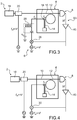
- the electrical diagram illustrating the coupling and the circulation of the coupling current is represented on the figure 6 .
- Cc represents the parasitic capacitance between the actuation electrode and the electrical tracks connected to the beam
- Rnems represents the resistance or impedance of the beam 14 or more generally of the mechanical part
- Ca represents the coupling capacity between the means of excitation and the mechanical part. We have It ⁇ Cc.
- the coupling capacitance Ca serves the capacitive actuation. This is a capacitance specific to the excitation circuit.
- Cpara represents the parasitic capacitance appearing between the electrical mass and the electrical access tracks and Cnems represents the capacitance which appears between the mechanical part and the mass.
- ic is the coupling current that appears due to the coupling Ca and Cc between the excitation means and the mechanical part, coupling mainly between the access tracks of the excitation means and the mechanical part (Cc). Since the Cpara capacity is much greater than the Cnems capacity, its impedance is lower than that of the Cnems capacity; the coupling current then flows towards the electrical ground through a parasitic capacitance between the access tracks and the ground (Cpara) and not through the mechanical part and the electrical ground (Cnems). The heating due to the joule effect is therefore significantly reduced compared to the systems of the state of the art due to the absence of current flowing through the NEMS resistor.
- ic circulates mainly through the capacitance Cpara to the electrical ground.
- the mechanical part symbolized by the impedance Rnems is connected directly to ground. There is then by parasitic capacitance Cpara. Self-heating is further reduced because all the current flows through this short circuit.
- the electrical diagram illustrating the coupling and the circulation of the coupling current is represented on the figure 7 .
- this component can advantageously be detected by a photodetector low bandwidth and having a low equivalent power of noise (NEP for Noise Equivalent Power in English terminology).
- NEP Noise Equivalent Power
- a common low frequency electronics such as an LIA can be used, which makes it possible to detect the phase of the resonator, from which it is possible to distinguish a coherent operation from an incoherent actuation and also to work in a loop mode. phase locked or PLL (Phase lock loop in English terminology).
- the factor M / 2 does not imply a loss of performance because the noise upstream of the photodiode, for example the thermomechanical noise is attenuated in the same way.
- the SNR is preserved.
- the ⁇ value of f is chosen to be above the measurement bandwidth determined by the mechanical resonator fr Qm .
- ⁇ f is chosen to be smaller than the bandwidth of the photodetector.
- the ratio fr / ⁇ f is then greater than or equal to 10, which makes it possible to have a good compromise between the bandwidth requirements and the needs for reducing the measurement frequency.
- ⁇ f> 10 kHz which allows to benefit from the full bandwidth of the resonator.
- ⁇ f> 100 kHz so one goes to a frequency for which the electronics has a lower noise.
- the invention makes it possible to perform measurements at other resonator resonance frequencies and thus to make measurements with several mechanical modes, in particular mechanical modes of higher order, while maintaining a good resolution. It is advantageous to repeat the measurements at different resonant frequencies in order to obtain more information on the deposited particles, such as their size and location, and to obtain a more complete result on the nature or mass of the particles.
- the adsorbed molecules are desorbed for example by heating the resonator.
- FIG. 2A another exemplary embodiment S2 of a measuring system according to the invention can be seen.
- the system S2 differs from the system S in that the optomechanical device uses the vibrating element directly as the vibrating element.
- the optical ring 112 is held on the support by means of spokes 120 connected to a fastener 122 to the support in the center of the ring.
- the excitation means comprise electrodes 124, in the shape of an arc of a circle, arranged facing the outer edge of the ring.
- the electrodes are for example fixed on the support.
- the excitation means 106 comprise two diametrically opposed electrodes. When the excitation means are activated, diametrically opposed forces apply to the optical ring 112 which deforms radially and "breathes". The optical ring then directly forms the resonator.
- the operation of the system S2 is close to the operation of the system S1, it differs in that the particles are deposited directly on the optical ring, which causes a modification of its resonance frequency fr2, the optical index is then modulated at the new frequency of resonance fr2, whereas before the deposition of particles the effective optical index was modulated to fr1.
- the effect on the amplitude of the luminous flux injected at fm + ⁇ f is thus modified.
- the system S3 comprises the elements of the system S1 and means 26 for mixing the signal at the output of the photodetection device at the frequency ⁇ f with an actuation signal at fm + ⁇ f, for example by multiplying the sinusoidal signals at ⁇ f and fm + ⁇ f so as to generate a signal at fm.
- This signal to which is added a DC signal V DC by means of a supply of T 28 or bias tee in English terminology, is applied to the electrode vibrating the movable element.
- a component 40 such as an amplifier or a filter downstream of the photodiode ensures the conditioning of the signal by output of the photodiode, ie it eliminates parasitic signals, and provides an amplification gain allowing the conditions of self-oscillations.
- the system S4 comprises the elements of the system S1 and means 30 adding the signal at the output of the photodetection device at the frequency ⁇ f with an actuating signal at fm + ⁇ f.
- a component 40 such as an amplifier 40 or a filter downstream of the photodiode ensures the conditioning of the signal at the output of the photodiode, ie it eliminates parasitic signals, and ensures a gain of amplification allowing self-oscillation conditions.
- the system can advantageously evaluate the actual resonant frequency of the continuously evaluated mechanical system and adapt using this value.
- the resonance frequency may vary over time, for example as a function of external elements during the deposition of particles or during their desorption.
- the resonant measuring system makes it possible to reduce the measurement background in the output signal and to maintain a high sensitivity and a high resolution.
- the output signal of the measurement system according to the invention obtained by a photodetector has a component in ⁇ f, it is possible to use a photodetector operating at low frequency and having a low bandwidth which is of a cost significantly lower than high bandwidth photodetectors. With a low bandwidth photodetector, even the high frequency modes outside the bandwidth of the photodetector are accessible since the value of ⁇ f is involved. It is then advantageously possible to make a detection at different modes and to obtain more complete information on the particles deposited in the case of particle detection.
- the fact of being able to use a low frequency photodetector contributes to improving the SNR because the input noise of such a photodetector is lower. only for high frequency photodetectors.
- these photodetectors have a high gain, they then have an easily readable electrical signal from a measuring instrument without adding noise of reading (Voltage noise density in English terminology) of the LIA or an oscilloscope.
- LIA synchronous detection amplifier
- LIA Lock in Amplifier
- the fact of having the phase makes it possible to work in phase-locked loop.
- the invention avoids the problems of control of electrical polarization related to the discontinuities of impedances and allows an effective modulation of the signal used for the measurement.
- the output signal is at the frequency ⁇ f which is chosen low, a low frequency electronics, for example operating between 1 MHz and 10 MHz, may be sufficient for the analog processing, digitization and all the elements of the chain of information processing. There is thus a gain in terms of energy consumption and ASIC space required for portable systems, autonomous or requiring a strong miniaturization.
- the system according to the invention can be manufactured by integrated circuit manufacturing technologies. It is suitable for very large scale integration (or VLSI for very-large-scale integration in English terminology).
- the device is made from an SOI (Silicon on Insulator) or silicon on insulator plate.
- SOI Silicon on Insulator
- the upper layer of silicon can be etched by photolithography to achieve the geometry of the ring, the waveguide and the resonant beam. Then a partial etching of the buried oxide (or Buried oxide in English terminology) is implemented to release the beam.
- the integration on the plate of the laser, the modulator and the photodetector can for example be carried out by support transfer techniques.
- the measurement system is particularly suitable for applications requiring both high frequency and high sensitivity.
- the application to the particle mass measurement for example in mass sensors has been more particularly described but it can be applied to achieve inertial sensors such as resonant accelerometers, gyrometers, in an atomic force microscope ...
Landscapes
- Physics & Mathematics (AREA)
- General Physics & Mathematics (AREA)
- Chemical & Material Sciences (AREA)
- Analytical Chemistry (AREA)
- Health & Medical Sciences (AREA)
- Life Sciences & Earth Sciences (AREA)
- Optics & Photonics (AREA)
- Biochemistry (AREA)
- General Health & Medical Sciences (AREA)
- Immunology (AREA)
- Pathology (AREA)
- Acoustics & Sound (AREA)
- Measurement Of Mechanical Vibrations Or Ultrasonic Waves (AREA)
Applications Claiming Priority (1)
| Application Number | Priority Date | Filing Date | Title |
|---|---|---|---|
| FR1653901A FR3050820B1 (fr) | 2016-04-29 | 2016-04-29 | Systeme de mesure resonant a resolution amelioree |
Publications (2)
| Publication Number | Publication Date |
|---|---|
| EP3244169A1 true EP3244169A1 (de) | 2017-11-15 |
| EP3244169B1 EP3244169B1 (de) | 2019-02-20 |
Family
ID=57136957
Family Applications (1)
| Application Number | Title | Priority Date | Filing Date |
|---|---|---|---|
| EP17167899.8A Active EP3244169B1 (de) | 2016-04-29 | 2017-04-25 | Resonanzmesssystem mit verbesserter auflösung |
Country Status (3)
| Country | Link |
|---|---|
| US (1) | US10416003B2 (de) |
| EP (1) | EP3244169B1 (de) |
| FR (1) | FR3050820B1 (de) |
Cited By (1)
| Publication number | Priority date | Publication date | Assignee | Title |
|---|---|---|---|---|
| EP4109049A1 (de) | 2021-06-25 | 2022-12-28 | Commissariat à l'énergie atomique et aux énergies alternatives | Messsystem vom typ mems oder nems mit mehreren sensoren |
Families Citing this family (4)
| Publication number | Priority date | Publication date | Assignee | Title |
|---|---|---|---|---|
| FR3061165B1 (fr) | 2016-12-22 | 2019-09-13 | Commissariat A L'energie Atomique Et Aux Energies Alternatives | Structure microelectronique a amortissement visqueux controle par maitrise de l'effet thermo-piezoresistif |
| WO2020086004A1 (en) * | 2018-10-26 | 2020-04-30 | National University Of Singapore | Thermocouple, thermopile and devices |
| FR3102855B1 (fr) * | 2019-11-06 | 2021-12-03 | Commissariat Energie Atomique | Accelerometre performant presentant un encombrement reduit |
| US11630123B2 (en) | 2020-08-18 | 2023-04-18 | Honeywell International Inc. | Opto-mechanical resonator with two or more frequency modes |
Citations (4)
| Publication number | Priority date | Publication date | Assignee | Title |
|---|---|---|---|---|
| WO2005081929A2 (en) * | 2004-02-25 | 2005-09-09 | California Institute Of Technology | Detection of resonator motion using piezoresistive signal downmixing |
| US20090238515A1 (en) * | 2008-03-19 | 2009-09-24 | David Fattal | Tunable Ring Resonator |
| WO2012113034A1 (en) * | 2011-02-25 | 2012-08-30 | Panorama Synergy Ltd | Optical cantilever based sample analysis |
| AU2016200064A1 (en) * | 2011-02-25 | 2016-01-28 | The University Of Western Australia | Optical sensor |
Family Cites Families (1)
| Publication number | Priority date | Publication date | Assignee | Title |
|---|---|---|---|---|
| WO2013052953A1 (en) * | 2011-10-08 | 2013-04-11 | Cornell University | Optomechanical sensors based on coupling between two optical cavities |
-
2016
- 2016-04-29 FR FR1653901A patent/FR3050820B1/fr not_active Expired - Fee Related
-
2017
- 2017-04-25 EP EP17167899.8A patent/EP3244169B1/de active Active
- 2017-04-27 US US15/499,292 patent/US10416003B2/en active Active
Patent Citations (4)
| Publication number | Priority date | Publication date | Assignee | Title |
|---|---|---|---|---|
| WO2005081929A2 (en) * | 2004-02-25 | 2005-09-09 | California Institute Of Technology | Detection of resonator motion using piezoresistive signal downmixing |
| US20090238515A1 (en) * | 2008-03-19 | 2009-09-24 | David Fattal | Tunable Ring Resonator |
| WO2012113034A1 (en) * | 2011-02-25 | 2012-08-30 | Panorama Synergy Ltd | Optical cantilever based sample analysis |
| AU2016200064A1 (en) * | 2011-02-25 | 2016-01-28 | The University Of Western Australia | Optical sensor |
Non-Patent Citations (3)
| Title |
|---|
| BARGATIN, E. B. MYERS; J. ARLETT; B. GUDLEWSKI; M. L. ROUKES: "Sensitive détection of nanomechanical motion using piezoresistive signal downmixing", APPL. PHYS. LETT., vol. 86, no. 13, 2005, pages 133109, XP012064852, DOI: doi:10.1063/1.1896103 |
| FAVERO 1.: "Cavity Optomechanics", 2014, article "Gallium Arsenide Disks as Optomechanical Resonators", pages: 149 - 156 |
| LEE JY; LU X; LIN Q: "High-Q silicon carbide photonic-crystal cavities", APPLIED PHYSICS LETTERS, vol. 106, no. 4, 26 January 2015 (2015-01-26), pages 041106, XP012194019, DOI: doi:10.1063/1.4906923 |
Cited By (2)
| Publication number | Priority date | Publication date | Assignee | Title |
|---|---|---|---|---|
| EP4109049A1 (de) | 2021-06-25 | 2022-12-28 | Commissariat à l'énergie atomique et aux énergies alternatives | Messsystem vom typ mems oder nems mit mehreren sensoren |
| FR3124592A1 (fr) | 2021-06-25 | 2022-12-30 | Commissariat A L'energie Atomique Et Aux Energies Alternatives | Système de mesure de type MEMS ou NEMS multicapteurs |
Also Published As
| Publication number | Publication date |
|---|---|
| EP3244169B1 (de) | 2019-02-20 |
| FR3050820A1 (fr) | 2017-11-03 |
| FR3050820B1 (fr) | 2018-04-13 |
| US10416003B2 (en) | 2019-09-17 |
| US20170314973A1 (en) | 2017-11-02 |
Similar Documents
| Publication | Publication Date | Title |
|---|---|---|
| EP3244169B1 (de) | Resonanzmesssystem mit verbesserter auflösung | |
| EP3147673B1 (de) | Optomechanischer physikalischer sensor mit verbesserter empfindlichkeit | |
| EP1068510B1 (de) | Verfahren zur wellenlängeneichung einer vorrichtung zur filterung elektromagnetischer strahlung | |
| FR2951545A1 (fr) | Detecteur de gaz photoacoustique | |
| WO2014114860A1 (fr) | Microscope à sonde locale multimode, microscope raman exalté par pointe et procédé de régulation de la distance entre la sonde locale et l'échantillon | |
| FR2985251A1 (fr) | Systeme pour detecter des reponses d'un dispositif resonateur micro-electromecanique ( mems) | |
| FR2977676A1 (fr) | Micro-systeme vibrant a boucle de controle automatique de gain, a controle integre du facteur de qualite | |
| EP3527967B1 (de) | Akustooptischer detektor mit optomechanischer kopplung | |
| WO1991003757A1 (fr) | Procede de microscopie et microscope en champ proche en reflexion | |
| EP0145534B1 (de) | Akustisches Gyrometer | |
| WO1993004347A1 (fr) | Microcapteur a poutre vibrante compense en temperature | |
| EP3044697B1 (de) | Elektronisches verfahren zur extraktion der amplitude und der phase eines signals in einer synchronen detektion und interferometrische anordnung zur durchführung des verfahrens | |
| EP3398252B1 (de) | Verstärkungsverfahren mit mechanischem resonator | |
| CN113607267A (zh) | 生物粒子机械振动特性探测的方法、装置和应用 | |
| WO2009063145A2 (fr) | Dispositif de detection heterodyne pour l'imagerie d'un objet par retroinjection | |
| EP4155717B1 (de) | Vorrichtung und verfahren zum nachweis chemischer oder biologischer spezies | |
| EP4109049B1 (de) | Messsystem vom typ mems oder nems mit mehreren sensoren | |
| EP2029998A1 (de) | Gesteuertes atomkraftmikroskop | |
| Zobenica et al. | Fully integrated nano-opto-electro-mechanical wavelength and displacement sensor | |
| FR2879752A1 (fr) | Sonde electro-optique de mesure de champs electriques ou electromagnetiques a asservissement optique par la longueur d'onde du point de fonctionnement | |
| WO2019149530A1 (fr) | Methode de determination d'une vitesse de sedimentation ou de cremage | |
| EP4187265A1 (de) | Vorrichtung und verfahren zur charakterisierung eines halbleitermaterials | |
| WO1990007250A1 (fr) | Microphone a detection interferometrique de pression acoustique | |
| EP0857964A1 (de) | Verfahren und Vorrichtung zur Messung von Gaskonzentrationen | |
| WO2001009661A1 (fr) | Dispositif permettant la determination de caracteristiques de la surface d'un objet. |
Legal Events
| Date | Code | Title | Description |
|---|---|---|---|
| PUAI | Public reference made under article 153(3) epc to a published international application that has entered the european phase |
Free format text: ORIGINAL CODE: 0009012 |
|
| STAA | Information on the status of an ep patent application or granted ep patent |
Free format text: STATUS: REQUEST FOR EXAMINATION WAS MADE |
|
| 17P | Request for examination filed |
Effective date: 20170425 |
|
| AK | Designated contracting states |
Kind code of ref document: A1 Designated state(s): AL AT BE BG CH CY CZ DE DK EE ES FI FR GB GR HR HU IE IS IT LI LT LU LV MC MK MT NL NO PL PT RO RS SE SI SK SM TR |
|
| AX | Request for extension of the european patent |
Extension state: BA ME |
|
| GRAP | Despatch of communication of intention to grant a patent |
Free format text: ORIGINAL CODE: EPIDOSNIGR1 |
|
| STAA | Information on the status of an ep patent application or granted ep patent |
Free format text: STATUS: GRANT OF PATENT IS INTENDED |
|
| RIC1 | Information provided on ipc code assigned before grant |
Ipc: G01D 5/34 20060101ALI20180719BHEP Ipc: G01L 9/00 20060101ALI20180719BHEP Ipc: G01N 29/036 20060101ALI20180719BHEP Ipc: G01D 5/26 20060101AFI20180719BHEP |
|
| INTG | Intention to grant announced |
Effective date: 20180820 |
|
| GRAS | Grant fee paid |
Free format text: ORIGINAL CODE: EPIDOSNIGR3 |
|
| GRAA | (expected) grant |
Free format text: ORIGINAL CODE: 0009210 |
|
| STAA | Information on the status of an ep patent application or granted ep patent |
Free format text: STATUS: THE PATENT HAS BEEN GRANTED |
|
| AK | Designated contracting states |
Kind code of ref document: B1 Designated state(s): AL AT BE BG CH CY CZ DE DK EE ES FI FR GB GR HR HU IE IS IT LI LT LU LV MC MK MT NL NO PL PT RO RS SE SI SK SM TR |
|
| REG | Reference to a national code |
Ref country code: GB Ref legal event code: FG4D Free format text: NOT ENGLISH |
|
| REG | Reference to a national code |
Ref country code: CH Ref legal event code: EP |
|
| REG | Reference to a national code |
Ref country code: DE Ref legal event code: R096 Ref document number: 602017002177 Country of ref document: DE |
|
| REG | Reference to a national code |
Ref country code: AT Ref legal event code: REF Ref document number: 1098797 Country of ref document: AT Kind code of ref document: T Effective date: 20190315 |
|
| REG | Reference to a national code |
Ref country code: IE Ref legal event code: FG4D Free format text: LANGUAGE OF EP DOCUMENT: FRENCH |
|
| REG | Reference to a national code |
Ref country code: LT Ref legal event code: MG4D Ref country code: NL Ref legal event code: MP Effective date: 20190220 |
|
| PG25 | Lapsed in a contracting state [announced via postgrant information from national office to epo] |
Ref country code: FI Free format text: LAPSE BECAUSE OF FAILURE TO SUBMIT A TRANSLATION OF THE DESCRIPTION OR TO PAY THE FEE WITHIN THE PRESCRIBED TIME-LIMIT Effective date: 20190220 Ref country code: LT Free format text: LAPSE BECAUSE OF FAILURE TO SUBMIT A TRANSLATION OF THE DESCRIPTION OR TO PAY THE FEE WITHIN THE PRESCRIBED TIME-LIMIT Effective date: 20190220 Ref country code: PT Free format text: LAPSE BECAUSE OF FAILURE TO SUBMIT A TRANSLATION OF THE DESCRIPTION OR TO PAY THE FEE WITHIN THE PRESCRIBED TIME-LIMIT Effective date: 20190620 Ref country code: SE Free format text: LAPSE BECAUSE OF FAILURE TO SUBMIT A TRANSLATION OF THE DESCRIPTION OR TO PAY THE FEE WITHIN THE PRESCRIBED TIME-LIMIT Effective date: 20190220 Ref country code: NO Free format text: LAPSE BECAUSE OF FAILURE TO SUBMIT A TRANSLATION OF THE DESCRIPTION OR TO PAY THE FEE WITHIN THE PRESCRIBED TIME-LIMIT Effective date: 20190520 |
|
| PG25 | Lapsed in a contracting state [announced via postgrant information from national office to epo] |
Ref country code: HR Free format text: LAPSE BECAUSE OF FAILURE TO SUBMIT A TRANSLATION OF THE DESCRIPTION OR TO PAY THE FEE WITHIN THE PRESCRIBED TIME-LIMIT Effective date: 20190220 Ref country code: RS Free format text: LAPSE BECAUSE OF FAILURE TO SUBMIT A TRANSLATION OF THE DESCRIPTION OR TO PAY THE FEE WITHIN THE PRESCRIBED TIME-LIMIT Effective date: 20190220 Ref country code: LV Free format text: LAPSE BECAUSE OF FAILURE TO SUBMIT A TRANSLATION OF THE DESCRIPTION OR TO PAY THE FEE WITHIN THE PRESCRIBED TIME-LIMIT Effective date: 20190220 Ref country code: NL Free format text: LAPSE BECAUSE OF FAILURE TO SUBMIT A TRANSLATION OF THE DESCRIPTION OR TO PAY THE FEE WITHIN THE PRESCRIBED TIME-LIMIT Effective date: 20190220 Ref country code: GR Free format text: LAPSE BECAUSE OF FAILURE TO SUBMIT A TRANSLATION OF THE DESCRIPTION OR TO PAY THE FEE WITHIN THE PRESCRIBED TIME-LIMIT Effective date: 20190521 Ref country code: IS Free format text: LAPSE BECAUSE OF FAILURE TO SUBMIT A TRANSLATION OF THE DESCRIPTION OR TO PAY THE FEE WITHIN THE PRESCRIBED TIME-LIMIT Effective date: 20190620 Ref country code: BG Free format text: LAPSE BECAUSE OF FAILURE TO SUBMIT A TRANSLATION OF THE DESCRIPTION OR TO PAY THE FEE WITHIN THE PRESCRIBED TIME-LIMIT Effective date: 20190520 |
|
| REG | Reference to a national code |
Ref country code: AT Ref legal event code: MK05 Ref document number: 1098797 Country of ref document: AT Kind code of ref document: T Effective date: 20190220 |
|
| PG25 | Lapsed in a contracting state [announced via postgrant information from national office to epo] |
Ref country code: EE Free format text: LAPSE BECAUSE OF FAILURE TO SUBMIT A TRANSLATION OF THE DESCRIPTION OR TO PAY THE FEE WITHIN THE PRESCRIBED TIME-LIMIT Effective date: 20190220 Ref country code: DK Free format text: LAPSE BECAUSE OF FAILURE TO SUBMIT A TRANSLATION OF THE DESCRIPTION OR TO PAY THE FEE WITHIN THE PRESCRIBED TIME-LIMIT Effective date: 20190220 Ref country code: ES Free format text: LAPSE BECAUSE OF FAILURE TO SUBMIT A TRANSLATION OF THE DESCRIPTION OR TO PAY THE FEE WITHIN THE PRESCRIBED TIME-LIMIT Effective date: 20190220 Ref country code: CZ Free format text: LAPSE BECAUSE OF FAILURE TO SUBMIT A TRANSLATION OF THE DESCRIPTION OR TO PAY THE FEE WITHIN THE PRESCRIBED TIME-LIMIT Effective date: 20190220 Ref country code: RO Free format text: LAPSE BECAUSE OF FAILURE TO SUBMIT A TRANSLATION OF THE DESCRIPTION OR TO PAY THE FEE WITHIN THE PRESCRIBED TIME-LIMIT Effective date: 20190220 Ref country code: IT Free format text: LAPSE BECAUSE OF FAILURE TO SUBMIT A TRANSLATION OF THE DESCRIPTION OR TO PAY THE FEE WITHIN THE PRESCRIBED TIME-LIMIT Effective date: 20190220 Ref country code: SK Free format text: LAPSE BECAUSE OF FAILURE TO SUBMIT A TRANSLATION OF THE DESCRIPTION OR TO PAY THE FEE WITHIN THE PRESCRIBED TIME-LIMIT Effective date: 20190220 Ref country code: AL Free format text: LAPSE BECAUSE OF FAILURE TO SUBMIT A TRANSLATION OF THE DESCRIPTION OR TO PAY THE FEE WITHIN THE PRESCRIBED TIME-LIMIT Effective date: 20190220 |
|
| REG | Reference to a national code |
Ref country code: DE Ref legal event code: R097 Ref document number: 602017002177 Country of ref document: DE |
|
| PG25 | Lapsed in a contracting state [announced via postgrant information from national office to epo] |
Ref country code: PL Free format text: LAPSE BECAUSE OF FAILURE TO SUBMIT A TRANSLATION OF THE DESCRIPTION OR TO PAY THE FEE WITHIN THE PRESCRIBED TIME-LIMIT Effective date: 20190220 Ref country code: SM Free format text: LAPSE BECAUSE OF FAILURE TO SUBMIT A TRANSLATION OF THE DESCRIPTION OR TO PAY THE FEE WITHIN THE PRESCRIBED TIME-LIMIT Effective date: 20190220 |
|
| REG | Reference to a national code |
Ref country code: BE Ref legal event code: MM Effective date: 20190430 |
|
| PLBE | No opposition filed within time limit |
Free format text: ORIGINAL CODE: 0009261 |
|
| STAA | Information on the status of an ep patent application or granted ep patent |
Free format text: STATUS: NO OPPOSITION FILED WITHIN TIME LIMIT |
|
| PG25 | Lapsed in a contracting state [announced via postgrant information from national office to epo] |
Ref country code: AT Free format text: LAPSE BECAUSE OF FAILURE TO SUBMIT A TRANSLATION OF THE DESCRIPTION OR TO PAY THE FEE WITHIN THE PRESCRIBED TIME-LIMIT Effective date: 20190220 Ref country code: LU Free format text: LAPSE BECAUSE OF NON-PAYMENT OF DUE FEES Effective date: 20190425 Ref country code: MC Free format text: LAPSE BECAUSE OF FAILURE TO SUBMIT A TRANSLATION OF THE DESCRIPTION OR TO PAY THE FEE WITHIN THE PRESCRIBED TIME-LIMIT Effective date: 20190220 |
|
| 26N | No opposition filed |
Effective date: 20191121 |
|
| PG25 | Lapsed in a contracting state [announced via postgrant information from national office to epo] |
Ref country code: SI Free format text: LAPSE BECAUSE OF FAILURE TO SUBMIT A TRANSLATION OF THE DESCRIPTION OR TO PAY THE FEE WITHIN THE PRESCRIBED TIME-LIMIT Effective date: 20190220 Ref country code: BE Free format text: LAPSE BECAUSE OF NON-PAYMENT OF DUE FEES Effective date: 20190430 |
|
| PG25 | Lapsed in a contracting state [announced via postgrant information from national office to epo] |
Ref country code: TR Free format text: LAPSE BECAUSE OF FAILURE TO SUBMIT A TRANSLATION OF THE DESCRIPTION OR TO PAY THE FEE WITHIN THE PRESCRIBED TIME-LIMIT Effective date: 20190220 |
|
| PG25 | Lapsed in a contracting state [announced via postgrant information from national office to epo] |
Ref country code: IE Free format text: LAPSE BECAUSE OF NON-PAYMENT OF DUE FEES Effective date: 20190425 |
|
| REG | Reference to a national code |
Ref country code: CH Ref legal event code: PL |
|
| PG25 | Lapsed in a contracting state [announced via postgrant information from national office to epo] |
Ref country code: LI Free format text: LAPSE BECAUSE OF NON-PAYMENT OF DUE FEES Effective date: 20200430 Ref country code: CH Free format text: LAPSE BECAUSE OF NON-PAYMENT OF DUE FEES Effective date: 20200430 |
|
| PG25 | Lapsed in a contracting state [announced via postgrant information from national office to epo] |
Ref country code: CY Free format text: LAPSE BECAUSE OF FAILURE TO SUBMIT A TRANSLATION OF THE DESCRIPTION OR TO PAY THE FEE WITHIN THE PRESCRIBED TIME-LIMIT Effective date: 20190220 |
|
| PG25 | Lapsed in a contracting state [announced via postgrant information from national office to epo] |
Ref country code: MT Free format text: LAPSE BECAUSE OF FAILURE TO SUBMIT A TRANSLATION OF THE DESCRIPTION OR TO PAY THE FEE WITHIN THE PRESCRIBED TIME-LIMIT Effective date: 20190220 Ref country code: HU Free format text: LAPSE BECAUSE OF FAILURE TO SUBMIT A TRANSLATION OF THE DESCRIPTION OR TO PAY THE FEE WITHIN THE PRESCRIBED TIME-LIMIT; INVALID AB INITIO Effective date: 20170425 |
|
| PG25 | Lapsed in a contracting state [announced via postgrant information from national office to epo] |
Ref country code: MK Free format text: LAPSE BECAUSE OF FAILURE TO SUBMIT A TRANSLATION OF THE DESCRIPTION OR TO PAY THE FEE WITHIN THE PRESCRIBED TIME-LIMIT Effective date: 20190220 |
|
| PGFP | Annual fee paid to national office [announced via postgrant information from national office to epo] |
Ref country code: FR Payment date: 20230424 Year of fee payment: 7 Ref country code: DE Payment date: 20230418 Year of fee payment: 7 |
|
| PGFP | Annual fee paid to national office [announced via postgrant information from national office to epo] |
Ref country code: GB Payment date: 20230421 Year of fee payment: 7 |