EP3244048A1 - Knocking control method - Google Patents
Knocking control method Download PDFInfo
- Publication number
- EP3244048A1 EP3244048A1 EP15876986.9A EP15876986A EP3244048A1 EP 3244048 A1 EP3244048 A1 EP 3244048A1 EP 15876986 A EP15876986 A EP 15876986A EP 3244048 A1 EP3244048 A1 EP 3244048A1
- Authority
- EP
- European Patent Office
- Prior art keywords
- knocking
- air cylinders
- gas
- control
- power generation
- Prior art date
- Legal status (The legal status is an assumption and is not a legal conclusion. Google has not performed a legal analysis and makes no representation as to the accuracy of the status listed.)
- Granted
Links
Images


Classifications
-
- F—MECHANICAL ENGINEERING; LIGHTING; HEATING; WEAPONS; BLASTING
- F02—COMBUSTION ENGINES; HOT-GAS OR COMBUSTION-PRODUCT ENGINE PLANTS
- F02D—CONTROLLING COMBUSTION ENGINES
- F02D35/00—Controlling engines, dependent on conditions exterior or interior to engines, not otherwise provided for
- F02D35/02—Controlling engines, dependent on conditions exterior or interior to engines, not otherwise provided for on interior conditions
- F02D35/027—Controlling engines, dependent on conditions exterior or interior to engines, not otherwise provided for on interior conditions using knock sensors
-
- F—MECHANICAL ENGINEERING; LIGHTING; HEATING; WEAPONS; BLASTING
- F02—COMBUSTION ENGINES; HOT-GAS OR COMBUSTION-PRODUCT ENGINE PLANTS
- F02D—CONTROLLING COMBUSTION ENGINES
- F02D17/00—Controlling engines by cutting out individual cylinders; Rendering engines inoperative or idling
-
- F—MECHANICAL ENGINEERING; LIGHTING; HEATING; WEAPONS; BLASTING
- F02—COMBUSTION ENGINES; HOT-GAS OR COMBUSTION-PRODUCT ENGINE PLANTS
- F02D—CONTROLLING COMBUSTION ENGINES
- F02D19/00—Controlling engines characterised by their use of non-liquid fuels, pluralities of fuels, or non-fuel substances added to the combustible mixtures
- F02D19/02—Controlling engines characterised by their use of non-liquid fuels, pluralities of fuels, or non-fuel substances added to the combustible mixtures peculiar to engines working with gaseous fuels
-
- F—MECHANICAL ENGINEERING; LIGHTING; HEATING; WEAPONS; BLASTING
- F02—COMBUSTION ENGINES; HOT-GAS OR COMBUSTION-PRODUCT ENGINE PLANTS
- F02D—CONTROLLING COMBUSTION ENGINES
- F02D41/00—Electrical control of supply of combustible mixture or its constituents
- F02D41/0025—Controlling engines characterised by use of non-liquid fuels, pluralities of fuels, or non-fuel substances added to the combustible mixtures
- F02D41/0027—Controlling engines characterised by use of non-liquid fuels, pluralities of fuels, or non-fuel substances added to the combustible mixtures the fuel being gaseous
-
- F—MECHANICAL ENGINEERING; LIGHTING; HEATING; WEAPONS; BLASTING
- F02—COMBUSTION ENGINES; HOT-GAS OR COMBUSTION-PRODUCT ENGINE PLANTS
- F02D—CONTROLLING COMBUSTION ENGINES
- F02D41/00—Electrical control of supply of combustible mixture or its constituents
- F02D41/008—Controlling each cylinder individually
- F02D41/0087—Selective cylinder activation, i.e. partial cylinder operation
-
- F—MECHANICAL ENGINEERING; LIGHTING; HEATING; WEAPONS; BLASTING
- F02—COMBUSTION ENGINES; HOT-GAS OR COMBUSTION-PRODUCT ENGINE PLANTS
- F02D—CONTROLLING COMBUSTION ENGINES
- F02D43/00—Conjoint electrical control of two or more functions, e.g. ignition, fuel-air mixture, recirculation, supercharging or exhaust-gas treatment
- F02D43/04—Conjoint electrical control of two or more functions, e.g. ignition, fuel-air mixture, recirculation, supercharging or exhaust-gas treatment using only digital means
-
- F—MECHANICAL ENGINEERING; LIGHTING; HEATING; WEAPONS; BLASTING
- F02—COMBUSTION ENGINES; HOT-GAS OR COMBUSTION-PRODUCT ENGINE PLANTS
- F02P—IGNITION, OTHER THAN COMPRESSION IGNITION, FOR INTERNAL-COMBUSTION ENGINES; TESTING OF IGNITION TIMING IN COMPRESSION-IGNITION ENGINES
- F02P5/00—Advancing or retarding ignition; Control therefor
- F02P5/04—Advancing or retarding ignition; Control therefor automatically, as a function of the working conditions of the engine or vehicle or of the atmospheric conditions
- F02P5/145—Advancing or retarding ignition; Control therefor automatically, as a function of the working conditions of the engine or vehicle or of the atmospheric conditions using electrical means
- F02P5/15—Digital data processing
- F02P5/152—Digital data processing dependent on pinking
-
- F—MECHANICAL ENGINEERING; LIGHTING; HEATING; WEAPONS; BLASTING
- F02—COMBUSTION ENGINES; HOT-GAS OR COMBUSTION-PRODUCT ENGINE PLANTS
- F02D—CONTROLLING COMBUSTION ENGINES
- F02D19/00—Controlling engines characterised by their use of non-liquid fuels, pluralities of fuels, or non-fuel substances added to the combustible mixtures
- F02D19/02—Controlling engines characterised by their use of non-liquid fuels, pluralities of fuels, or non-fuel substances added to the combustible mixtures peculiar to engines working with gaseous fuels
- F02D19/021—Control of components of the fuel supply system
- F02D19/023—Control of components of the fuel supply system to adjust the fuel mass or volume flow
- F02D19/024—Control of components of the fuel supply system to adjust the fuel mass or volume flow by controlling fuel injectors
-
- F—MECHANICAL ENGINEERING; LIGHTING; HEATING; WEAPONS; BLASTING
- F02—COMBUSTION ENGINES; HOT-GAS OR COMBUSTION-PRODUCT ENGINE PLANTS
- F02D—CONTROLLING COMBUSTION ENGINES
- F02D2250/00—Engine control related to specific problems or objectives
- F02D2250/18—Control of the engine output torque
- F02D2250/26—Control of the engine output torque by applying a torque limit
-
- F—MECHANICAL ENGINEERING; LIGHTING; HEATING; WEAPONS; BLASTING
- F02—COMBUSTION ENGINES; HOT-GAS OR COMBUSTION-PRODUCT ENGINE PLANTS
- F02P—IGNITION, OTHER THAN COMPRESSION IGNITION, FOR INTERNAL-COMBUSTION ENGINES; TESTING OF IGNITION TIMING IN COMPRESSION-IGNITION ENGINES
- F02P5/00—Advancing or retarding ignition; Control therefor
- F02P5/04—Advancing or retarding ignition; Control therefor automatically, as a function of the working conditions of the engine or vehicle or of the atmospheric conditions
- F02P5/145—Advancing or retarding ignition; Control therefor automatically, as a function of the working conditions of the engine or vehicle or of the atmospheric conditions using electrical means
- F02P5/15—Digital data processing
- F02P5/152—Digital data processing dependent on pinking
- F02P5/1522—Digital data processing dependent on pinking with particular means concerning an individual cylinder
Definitions
- the present invention relates to a knocking control method in a gas engine used for a power generation system.
- Patent Literature 1 discloses a control device in which, when it is determined that knocking has occurred in any of the air cylinders in a gas engine on the basis of a value detected using a knock sensor, a supply amount and pressure of a gas with respect to all of the air cylinders are reduced so that a load is lowered or an ignition timing is delayed (a timing retard) and thus the occurrence of knocking is minimized.
- the present invention provides a knocking control method in which knocking is minimized while suppressing a decrease in the amount of electric power generation in a power generation system and thus electricity can be stably generated.
- a knocking control method in a power generation system which includes a gas engine including a plurality of air cylinders and a knocking detection unit configured to detect knocking in each of the air cylinders
- the knocking control method including: a first control step of delaying an ignition timing for at least one of the air cylinders when the knocking detection unit has detected knocking; a second control step of performing load reducing in at least one of the air cylinders when the knocking has not been eliminated by the first control step; and a third control step of shutting off supply of a gas to any of the air cylinders in which knocking has occurred.
- an ignition timing of at least one of the air cylinders in the first control step is delayed so that knocking can be minimized without reducing an amount of electric power generation in the power generation system. Furthermore, since the operation of the gas engine can continue while an ignition timing of the other air cylinders is maintained, a decrease in combustion efficiency in the other air cylinders and a resulting increase in the amount of consumption of a gas can be minimized.
- the first to third control steps are performed step by step in this way so that knocking can be minimized while an ignition timing of the normally operating air cylinders is delayed or the total amount of a gas supplied to the gas engine is significantly reduced.
- a decrease in the amount of electric power generation of the power generation system can be minimized and thus electricity can be stably generated.
- the at least one air cylinder may include an air cylinder in which knocking has occurred among the plurality of air cylinders included in the gas engine.
- the first control step and the second control step can be performed in any of the air cylinders in which knocking has occurred. For this reason, knocking can be minimized without changing an ignition timing of normally operating air cylinders and a gas supply amount. Thus, a decrease in combustion efficiency and an increase in the amount of consumption of a gas occurring when an ignition timing has been delayed in normally operating air cylinders can be minimized. Furthermore, when an exhaust temperature in normally operating air cylinders rises, it is possible to prevent a combustion abnormality such as knocking from likely occurring in normally operating air cylinders.
- the at least one air cylinder may include all of the air cylinders included in the gas engine.
- the total amount of a gas supplied to the gas engine may be reduced at the time of the third control step.
- an increase in the amount of gas supplied to normally operating air cylinders can be suppressed by an amount in which supply of a gas to any of the air cylinders in which knocking has occurred is shut off. For this reason, it is possible to prevent the durability of the gas engine from being lowered or knocking from very likely occurring in normally operating air cylinders due to a gas of a predetermined amount or more being supplied to normally operating air cylinders so that the normally operating air cylinders have an overload condition.
- the power generation system 1 includes a gas engine 20, a generator 10 connected to the gas engine 20 via a rotating shaft 24 and configured to generate electricity using a rotational driving force of the gas engine 20, and a control unit 50 configured to control the gas engine 20 and the generator 10.
- the gas engine 20 includes a plurality of air cylinders 21.
- Gas supply pipes 22 configured to supply a gas G from a gas supply unit 30 are connected to the air cylinders 21.
- Solenoid valves 23 are provided in the gas supply pipes 22 connected to the air cylinders 21.
- the gas supply pipes 22 are opened and closed using the solenoid valves 23 so that an amount of a gas G supplied from the gas supply pipes 22 to the air cylinders 21 is adjusted or supply of the gas G is stopped (shut off).
- knock sensors 25 configured to detect knocking in the air cylinders 21 are provided in the air cylinders 21. Examples of the knock sensors 25 include an acceleration sensor.-
- the gas engine 20 includes 18 air cylinders 21.
- 18 gas supply pipes 22 are connected to the 18 air cylinders 21, respectively and 18 solenoid valves 23 are provided in the 18 gas supply pipes 22, respectively.
- Spark plugs (not shown) configured to ignite a gas G supplied from the gas supply pipes 22 into the air cylinders 21 and combust the gas G are provided inside the air cylinders 21 in the gas engine 20.
- the spark plugs are controlled to be ignited by an ignition 40 at arbitrary timings
- the control unit 50 includes a knocking detection unit 51 configured to determine whether knocking has occurred on the basis of signals from the knock sensors 25 provided in the air cylinders 21 and an engine control unit 52 configured to control the gas supply unit 30 used to adjust supply of a gas G to the gas engine 20 and the ignition 40 used to adjust ignition timings of the spark plugs.
- the control unit 50 controls the gas supply unit 30 and the ignition 40 using the engine control unit 52 to adjust an amount of gas G supplied to the gas engine 20 and ignition timings of the air cylinders 21 in the gas engine 20 and controls an amount of electric power generation in the generator 10.
- the knocking detection unit 51 in the control unit 50 determines whether knocking (a knocking state) has occurred in the air cylinders 21 on the basis of signals from the knock sensors 25 in the air cylinders 21.
- Step ST01 when knocking has not occurred in any of the air cylinders 21, that is, when it is determined by the knocking detection unit 51 that knocking has not occurred in the air cylinders 21 (Step ST01: NO), the knocking detection unit 51 repeatedly performs the determination of Step ST01.
- Step ST01 when it is determined that knocking has occurred in any air cylinders 21 among the 18 air cylinders 21, for example, a "first air cylinder 21" (Step ST01: YES), the knocking detection unit 51 notifies the engine control unit 52 of information indicating that knocking has occurred in the "first air cylinder 21" (hereinafter referred to as a "knocking state notification").
- the engine control unit 52 starts delay control of an ignition timing of the "first air cylinder 21" when notified of the knocking state notification (Step ST02).
- the engine control unit 52 outputs a command to the ignition 40 so that the ignition timing of the "first air cylinder 21" is delayed by a predetermined value per unit time.
- the ignition 40 continuously delays the ignition timing of the "first air cylinder 21" for a predetermined period of time.
- a process of Step ST02 is referred to as a first control step.
- Delay control of an ignition timing is not limited to control performed on only the "first air cylinder 21."
- the delay control may be performed on a plurality of air cylinders 21 and may be performed on all air cylinders 21 included in the gas engine 20.
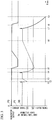
- Fig. 3 is a graph for describing an amount of electric power generation in the power generation system 1 and ignition timings in the air cylinders 21 of the gas engine 20 according to this embodiment.
- a horizontal axis in Fig. 3 indicates a time axis.
- a "generator output” described in an upper portion in Fig. 3 represents an amount of electric power generation output by the generator 10 in the graph.
- a vertical axis indicates the amount of electric power generation of the generator 10.
- an "ignition timing of each cylinder” described in a lower portion in Fig. 3 represents an ignition timing of each of the air cylinders 21 in the graph.
- An upper side of the vertical axis indicates a timing advance side and a lower side thereof indicates a timing delay side.
- an initial value of an ignition timing of the air cylinder 21 is set to V0.
- the first control step is performed and delay control of the ignition timing of the "first air cylinder 21" is started.
- the ignition timing of the "first air cylinder 21" is moved toward the timing delay side after t1 in Fig. 3 .
- an amount of electric power generation output by the generator 10 is not lowered.
- the knocking detection unit 51 When knocking has not occurred by the first control step at t2 in Fig. 3 , that is, when it is determined by the knocking detection unit 51 that knocking has not occurred in the "first air cylinder 21" (Step ST03: NO), the knocking detection unit 51 notifies the engine control unit 52 of information indicating that knocking of the "first air cylinder 21" has been removed (hereinafter referred to as a "knocking removal notification"). The engine control unit 52 terminates the delay control of the ignition timing of the "first air cylinder 21" when notified of the knocking removal notification (Step ST04).
- the engine control unit 52 outputs a command to the ignition 40 so that the timing of the "first air cylinder 21" is advanced to an initial value V0 by a predetermined value per unit time.
- the ignition timing of the "first air cylinder 21" is advanced to return to the initial value V0 as illustrated at t2 to t3 in Fig. 3 .
- Step ST03 YES
- Step ST05 NO
- the engine control unit 52 continues the delay control of the ignition timing of the "first air cylinder 21.” In other words, the engine control unit 52 delays the ignition timing of the "first air cylinder 21" by a predetermined value per unit time.
- the knocking detection unit 51 and the engine control unit 52 repeatedly perform the processes of Step ST03 and Step ST05.
- Step ST03 when it is determined by the knocking detection unit 51 that knocking has occurred in the "first air cylinder 21" as illustrated at t5 in Fig. 3 (Step ST03: YES) and a predetermined time has elapsed from the start of the delay control of the ignition timing of the "first air cylinder 21" (Step ST05: YES), the engine control unit 52 starts temporary load reducing (Step ST06).
- the engine control unit 52 outputs a command to the gas supply unit 30 so that the total amount of gas G supplied to the gas engine 20 (all air cylinders 21 included in the gas engine 20) is reduced by a predetermined amount (for example, decreased by 5% with respect to a specified amount of the gas G supplied to the gas engine 20).
- a predetermined amount for example, decreased by 5% with respect to a specified amount of the gas G supplied to the gas engine 20.
- the delay control of the ignition timing of the "first air cylinder 21" continues and thus the timing is delayed by a predetermined value per unit time.
- a process of Step ST06 is referred to as a second control step.
- Temporary load reducing is not limited to reducing the total amount of the gas G supplied to the gas engine 20, may include reducing an amount of the gas G supplied to a "first air cylinder 21," and may include reducing an amount of the gas G supplied to a plurality of first air cylinders 21. Furthermore, examples of the temporary load reducing may include reducing a pressure of the gas G in comparison with a specified pressure.
- the knocking detection unit 51 When it is determined by the knocking detection unit 51 that knocking has not occurred in the "first air cylinder 21" through the second control step (Step ST07: NO), the knocking detection unit 51 notifies the engine control unit 52 of a knocking removal notification of the "first air cylinder 21.” The engine control unit 52 terminates the temporary load reducing when notified of the knocking removal notification and terminates the delay control of the ignition timing of the "first air cylinder 21" (Step ST08). To be specific, the engine control unit 52 outputs a command to the gas supply unit 30 so that the total amount of the gas G supplied to the gas engine 20 is restored to a specified amount.
- the engine control unit 52 outputs a command to the ignition 40 so that the ignition timing of the "first air cylinder 21" is advanced to the initial value V0.
- the engine control unit 52 outputs a command to the ignition 40 so that the ignition timing of the "first air cylinder 21" is advanced to the initial value V0.
- a process of the knocking detection unit 51 returns to a process of Step ST01 and the process of Step ST01 is repeated.
- Step ST07 YES
- Step ST09 NO
- the engine control unit 52 continues the delay control of the ignition timing of the "first air cylinder 21.”
- the engine control unit 52 delays the ignition timing of the "first air cylinder 21" by a predetermined value per unit time.
- the knocking detection unit 51 and the engine control unit 52 repeat the processes of Step ST07 and Step ST09.
- Step ST10 when the number of air cylinders 21 which have stopped operating is less than two (Step ST10: YES), the engine control unit 52 outputs a command to the gas supply unit 30 so that supply of the gas G to the "first air cylinder 21" is stopped. Thus, the operation of the "first air cylinder 21" stops. Furthermore, the engine control unit 52 outputs a command to the gas supply unit 30 so that load reducing control of the gas engine 20 is started. To be specific, the engine control unit 52 outputs a command to the gas supply unit 30 so that the total amount of the gas G supplied to the gas engine 20 is reduced by an amount corresponding to the number of the air cylinders 21 to which supply of the gas G is stopped (Step ST11).
- Step ST11 is referred to as a third control step.
- control unit 50 may perform the third control step and notify a manager or the like of the power generation system 1 that the operation of a "first air cylinder 21" has stopped using an alert.
- an output amount of the generator 10 is reduced in comparison with the specified output amount P0 along with the reduction of the total supply amount of the gas G and is reduced, for example, up to the output amount P1. Note that, since supply of a gas G to a "first air cylinder 21" is stopped, that is, the operation of the "first air cylinder 21" stops, delay control performed on the "first air cylinder 21" is also terminated.
- a process of the knocking detection unit 51 returns to a process of Step ST01 and the process of Step ST01 is repeated. Furthermore, the operation of the gas engine 20 continues while the operation of the "first air cylinder 21" has stopped.
- Step ST10 when the operation of two of the air cylinders 21 has already stopped by the third control step, for example, when the operation of the "first air cylinder 21" and a "second air cylinder 21" has stopped, if knocking is detected in another air cylinder 21 (for example, a "third air cylinder 21") and a knocking state is not removed even in the first and second control steps (Step ST10: NO), the engine control unit 52 determines that it is difficult to continue the operation of the gas engine 20. For this reason, the engine control unit 52 outputs a command to the gas supply unit 30 so that supply of the gas G to the gas engine 20 is stopped (Step ST12). A process of Step ST12 is referred to as a fourth control step.
- control unit 50 may perform the fourth control step and notify the manager or the like of the power generation system 1 that the operation of the gas engine 20 has stopped using an alert.
- the control unit 50 can delay an ignition timing of at least one of the air cylinders 21 in the first control step to control knocking without reducing an amount of electric power generation in the power generation system 1 from the specified output amount P0. Furthermore, since the operation of the gas engine 20 can continue while an ignition timing of the other air cylinders 21 is maintained, a decrease in combustion efficiency in the other air cylinders 21 and a resulting increase in the amount of consumption of the gas G can be minimized.
- an amount of the gas G supplied to at least one of the air cylinders 21 can be reduced in the second control step to lower a load of the at least one air cylinder 21 so that the total amount of the gas G supplied to the entire gas engine 20 is not significantly reduced. For this reason, knocking can be minimized while a decrease in the amount of electric power generation in the power generation system 1 is minimized.
- the first to third control steps are performed step by step in this way so that knocking can be minimized while a decrease in the amount of electric power generation in the power generation system is minimized. Thus, electricity can be stably generated in the power generation system 1.
- the first control step and the second control step may be performed on only any of the air cylinders 21 for which knocking is determined to have occurred therein. For this reason, knocking can be minimized without changing an ignition timing and a gas G supply amount of normally operating air cylinders 21, that is, any of the air cylinders 21 in which knocking has not occurred. Thus, a decrease in combustion efficiency and an increase in the amount of consumption of the gas G which occur when an ignition timing has been delayed in the normally operating air cylinders 21 can be minimized. Furthermore, when an exhaust temperature of the normally operating air cylinders 21 rises, it is possible to minimize the likely occurrence of a combustion abnormality such as knocking in the normally operating air cylinders 21. For this reason, in the power generation system 1, a combustion abnormality in the air cylinders 21 is minimized and thus electricity can be stably generated.
- the first control step and the second control step may be performed on all of the air cylinders 21 included in the gas engine 20.
- a load applied to the air cylinders 21 can be sufficiently reduced and thus knocking can be minimized more safely.
- the total amount of the gas G supplied to the gas engine 20 may be reduced by an amount corresponding to the number of air cylinders 21 which have stopped operating.
- an increase in the amount of the gas G supplied to the normally operating air cylinders 21 can be minimized.
- a combustion abnormality in the air cylinders 21 is minimized and thus electricity can be stably generated.
- the control unit 50 may stop supply of the gas G to the gas engine 20 by the fourth control step.
- the control unit 50 may stop supply of the gas G to the gas engine 20 by the fourth control step.
- the manager or the like of the power generation system 1 is notified using an alert.
- the manager or the like of the power generation system 1 can easily ascertain that the operation of an air cylinder 21 in the gas engine 20 has stopped or the operation of the gas engine 20 has stopped.
- the gas engine 20 has 18 air cylinders 21
- the number of air cylinders 21 is not limited to 18 and any number may be used.
- a control method of performing the second control step when knocking is detected even after a predetermined time has elapsed from the performing of the first control step in the above-described embodiment has been described.
- the present invention is not limited to such a control method.
- the second control step may be performed.
- the third control step may be performed. Even with such control, the same effects as those of the above-described embodiment can be obtained.
- the manager or the like of the power generation system 1 is notified using an alert.
- the present invention is not limited to such a control method.
- the manager or the like of the power generation system 1 may be notified using an alert. The manager or the like of the power generation system 1 can easily ascertain a state of the power generation system 1 through such control.
- knocking is minimized while a decrease in the amount of electric power generation in a power generation system is minimized so that electricity can be stably generated.
Landscapes
- Engineering & Computer Science (AREA)
- Chemical & Material Sciences (AREA)
- Combustion & Propulsion (AREA)
- Mechanical Engineering (AREA)
- General Engineering & Computer Science (AREA)
- Signal Processing (AREA)
- Combined Controls Of Internal Combustion Engines (AREA)
- Electrical Control Of Ignition Timing (AREA)
- Output Control And Ontrol Of Special Type Engine (AREA)
- Electrical Control Of Air Or Fuel Supplied To Internal-Combustion Engine (AREA)
Abstract
Description
- The present invention relates to a knocking control method in a gas engine used for a power generation system.
- Priority is claimed on Japanese Patent Application No.
2015-002266, filed January 8, 2015 - In power generation systems using gas engines, in order to stably generate electricity, a combustion abnormality such as knocking needs to be found at an early stage to be prevented.
- For example, Patent Literature 1 discloses a control device in which, when it is determined that knocking has occurred in any of the air cylinders in a gas engine on the basis of a value detected using a knock sensor, a supply amount and pressure of a gas with respect to all of the air cylinders are reduced so that a load is lowered or an ignition timing is delayed (a timing retard) and thus the occurrence of knocking is minimized.
- Japanese Unexamined Patent Application, First Publication No.
2012-159048 - However, in the above knocking control method, control is performed on all of the air cylinders provided in the gas engine so that a load is uniformly lowered or an ignition timing is delayed. Since an ignition timing of air cylinders in which knocking has not occurred, that is, normally operating air cylinders, is also delayed when such control is performed, combustion efficiency is lowered and thus an amount of consumption of a gas is likely to be increased. Furthermore, an exhaust temperature in the normally operating air cylinders rises and thus a combustion abnormality such as knocking is also very likely to occur in the normally operating air cylinders. Thus, combustion efficiency in the entire gas engine is lowered and thus an amount of electric power generation in the power generation system is likely to be lowered. For this reason, electricity is less likely to be stably generated without maintaining a constant amount of electric power generation in the power generation system.
- The present invention provides a knocking control method in which knocking is minimized while suppressing a decrease in the amount of electric power generation in a power generation system and thus electricity can be stably generated.
- According to a first aspect of the present invention, a knocking control method in a power generation system which includes a gas engine including a plurality of air cylinders and a knocking detection unit configured to detect knocking in each of the air cylinders, the knocking control method including: a first control step of delaying an ignition timing for at least one of the air cylinders when the knocking detection unit has detected knocking; a second control step of performing load reducing in at least one of the air cylinders when the knocking has not been eliminated by the first control step; and a third control step of shutting off supply of a gas to any of the air cylinders in which knocking has occurred.
- According to such a knocking control method, an ignition timing of at least one of the air cylinders in the first control step is delayed so that knocking can be minimized without reducing an amount of electric power generation in the power generation system. Furthermore, since the operation of the gas engine can continue while an ignition timing of the other air cylinders is maintained, a decrease in combustion efficiency in the other air cylinders and a resulting increase in the amount of consumption of a gas can be minimized.
- Also, when knocking is not eliminated in the first control step, load reducing in at least one of the air cylinders is performed in the second control step so that a supply amount and pressure of a gas with respect to the entire gas engine is not significantly reduced and thus a load of the relevant air cylinder can be lowered. For this reason, knocking can be minimized while a decrease in the amount of electric power generation in the power generation system is minimized.
- In addition, when knocking is not eliminated in the second control step, supply of a gas to air cylinders in which knocking has occurred is shut off in the third control step so that knocking can be minimized in a state in which combustion in normally operating air cylinders continues. For this reason, knocking can be minimized while a decrease in the amount of electric power generation in the power generation system is minimized.
- The first to third control steps are performed step by step in this way so that knocking can be minimized while an ignition timing of the normally operating air cylinders is delayed or the total amount of a gas supplied to the gas engine is significantly reduced. Thus, a decrease in the amount of electric power generation of the power generation system can be minimized and thus electricity can be stably generated.
- According to a second aspect of the present invention, in the first aspect, the at least one air cylinder may include an air cylinder in which knocking has occurred among the plurality of air cylinders included in the gas engine.
- According to such a knocking control method, the first control step and the second control step can be performed in any of the air cylinders in which knocking has occurred. For this reason, knocking can be minimized without changing an ignition timing of normally operating air cylinders and a gas supply amount. Thus, a decrease in combustion efficiency and an increase in the amount of consumption of a gas occurring when an ignition timing has been delayed in normally operating air cylinders can be minimized. Furthermore, when an exhaust temperature in normally operating air cylinders rises, it is possible to prevent a combustion abnormality such as knocking from likely occurring in normally operating air cylinders.
- According to a third aspect of the present invention, in the first aspect, the at least one air cylinder may include all of the air cylinders included in the gas engine.
- According to such a knocking control method, since the first control step and the second control step can be performed in all of the air cylinders included in the gas engine, a load in the air cylinders can be sufficiently reduced and thus knocking can be minimized more safely.
- According to a fourth aspect of the present invention, in any one of the first to third aspects, the total amount of a gas supplied to the gas engine may be reduced at the time of the third control step.
- According to such a knocking control method, an increase in the amount of gas supplied to normally operating air cylinders can be suppressed by an amount in which supply of a gas to any of the air cylinders in which knocking has occurred is shut off. For this reason, it is possible to prevent the durability of the gas engine from being lowered or knocking from very likely occurring in normally operating air cylinders due to a gas of a predetermined amount or more being supplied to normally operating air cylinders so that the normally operating air cylinders have an overload condition.
- According to the above knocking control method, electricity can be stably generated by controlling knocking while a decrease in the amount of electric power generation in a power generation system is minimized.
-
-
Fig. 1 is a block diagram illustrating a power generation system according to an embodiment of the present invention. -
Fig. 2 is a flowchart for describing a knocking control method according to the embodiment of the present invention. -
Fig. 3 is a graph for describing an amount of electric power generation in a power generation system and ignition timings in air cylinders of a gas engine according to the embodiment of the present invention. - Hereinafter, a power generation system 1 according to an embodiment of the present invention will be described with reference to
Figs. 1 to 3 . - First, a constitution of the power generation system 1 in this embodiment will be described with reference to
Fig. 1 . - As shown in
Fig. 1 , in this embodiment, the power generation system 1 includes agas engine 20, agenerator 10 connected to thegas engine 20 via arotating shaft 24 and configured to generate electricity using a rotational driving force of thegas engine 20, and acontrol unit 50 configured to control thegas engine 20 and thegenerator 10. - The
gas engine 20 includes a plurality ofair cylinders 21.Gas supply pipes 22 configured to supply a gas G from agas supply unit 30 are connected to theair cylinders 21.Solenoid valves 23 are provided in thegas supply pipes 22 connected to theair cylinders 21. Thegas supply pipes 22 are opened and closed using thesolenoid valves 23 so that an amount of a gas G supplied from thegas supply pipes 22 to theair cylinders 21 is adjusted or supply of the gas G is stopped (shut off). Furthermore,knock sensors 25 configured to detect knocking in theair cylinders 21 are provided in theair cylinders 21. Examples of theknock sensors 25 include an acceleration sensor.- - In this embodiment, a case in which the
gas engine 20 includes 18air cylinders 21 will be described. 18gas supply pipes 22 are connected to the 18air cylinders 21, respectively and 18solenoid valves 23 are provided in the 18gas supply pipes 22, respectively. - Spark plugs (not shown) configured to ignite a gas G supplied from the
gas supply pipes 22 into theair cylinders 21 and combust the gas G are provided inside theair cylinders 21 in thegas engine 20. The spark plugs are controlled to be ignited by anignition 40 at arbitrary timings - The
control unit 50 includes aknocking detection unit 51 configured to determine whether knocking has occurred on the basis of signals from theknock sensors 25 provided in theair cylinders 21 and anengine control unit 52 configured to control thegas supply unit 30 used to adjust supply of a gas G to thegas engine 20 and theignition 40 used to adjust ignition timings of the spark plugs. Thecontrol unit 50 controls thegas supply unit 30 and theignition 40 using theengine control unit 52 to adjust an amount of gas G supplied to thegas engine 20 and ignition timings of theair cylinders 21 in thegas engine 20 and controls an amount of electric power generation in thegenerator 10. - Next, a knocking control method in the power generation system 1 in this embodiment will be described with reference to
Fig. 2 . - As illustrated in Step ST01 in
Fig. 2 , theknocking detection unit 51 in thecontrol unit 50 determines whether knocking (a knocking state) has occurred in theair cylinders 21 on the basis of signals from theknock sensors 25 in theair cylinders 21. - Here, when knocking has not occurred in any of the
air cylinders 21, that is, when it is determined by theknocking detection unit 51 that knocking has not occurred in the air cylinders 21 (Step ST01: NO), theknocking detection unit 51 repeatedly performs the determination of Step ST01. - Also, when it is determined that knocking has occurred in any
air cylinders 21 among the 18air cylinders 21, for example, a "first air cylinder 21" (Step ST01: YES), theknocking detection unit 51 notifies theengine control unit 52 of information indicating that knocking has occurred in the "first air cylinder 21" (hereinafter referred to as a "knocking state notification"). Theengine control unit 52 starts delay control of an ignition timing of the "first air cylinder 21" when notified of the knocking state notification (Step ST02). To be specific, theengine control unit 52 outputs a command to theignition 40 so that the ignition timing of the "first air cylinder 21" is delayed by a predetermined value per unit time. Theignition 40 continuously delays the ignition timing of the "first air cylinder 21" for a predetermined period of time. A process of Step ST02 is referred to as a first control step. - Delay control of an ignition timing is not limited to control performed on only the "
first air cylinder 21." In addition, the delay control may be performed on a plurality ofair cylinders 21 and may be performed on allair cylinders 21 included in thegas engine 20. -
Fig. 3 is a graph for describing an amount of electric power generation in the power generation system 1 and ignition timings in theair cylinders 21 of thegas engine 20 according to this embodiment. A horizontal axis inFig. 3 indicates a time axis. A "generator output" described in an upper portion inFig. 3 represents an amount of electric power generation output by thegenerator 10 in the graph. A vertical axis indicates the amount of electric power generation of thegenerator 10. Furthermore, an "ignition timing of each cylinder" described in a lower portion inFig. 3 represents an ignition timing of each of theair cylinders 21 in the graph. An upper side of the vertical axis indicates a timing advance side and a lower side thereof indicates a timing delay side. In this embodiment, an initial value of an ignition timing of theair cylinder 21 is set to V0. - When it is determined by the knocking
detection unit 51 that knocking has occurred in the "first air cylinder 21" at t1 inFig. 3 , the first control step is performed and delay control of the ignition timing of the "first air cylinder 21" is started. Thus, the ignition timing of the "first air cylinder 21" is moved toward the timing delay side after t1 inFig. 3 . At this time, an amount of electric power generation output by thegenerator 10 is not lowered. - When knocking has not occurred by the first control step at t2 in
Fig. 3 , that is, when it is determined by the knockingdetection unit 51 that knocking has not occurred in the "first air cylinder 21" (Step ST03: NO), the knockingdetection unit 51 notifies theengine control unit 52 of information indicating that knocking of the "first air cylinder 21" has been removed (hereinafter referred to as a "knocking removal notification"). Theengine control unit 52 terminates the delay control of the ignition timing of the "first air cylinder 21" when notified of the knocking removal notification (Step ST04). To be specific, theengine control unit 52 outputs a command to theignition 40 so that the timing of the "first air cylinder 21" is advanced to an initial value V0 by a predetermined value per unit time. Thus, the ignition timing of the "first air cylinder 21" is advanced to return to the initial value V0 as illustrated at t2 to t3 inFig. 3 . - Also, a case in which it is determined by the knocking
detection unit 51 that knocking has occurred in the "first air cylinder 21" at t4 inFig. 3 and thus the first control step is performed is illustrated. At this time, when it is determined by the knockingdetection unit 51 that knocking has occurred in the "first air cylinder 21" (Step ST03: YES) and a predetermined time does not elapse from the start of the delay control of the ignition timing of the "first air cylinder 21" (Step ST05: NO), theengine control unit 52 continues the delay control of the ignition timing of the "first air cylinder 21." In other words, theengine control unit 52 delays the ignition timing of the "first air cylinder 21" by a predetermined value per unit time. Moreover, the knockingdetection unit 51 and theengine control unit 52 repeatedly perform the processes of Step ST03 and Step ST05. - In addition, when such a state has continued, that is, when it is determined by the knocking
detection unit 51 that knocking has occurred in the "first air cylinder 21" as illustrated at t5 inFig. 3 (Step ST03: YES) and a predetermined time has elapsed from the start of the delay control of the ignition timing of the "first air cylinder 21" (Step ST05: YES), theengine control unit 52 starts temporary load reducing (Step ST06). To be specific, theengine control unit 52 outputs a command to thegas supply unit 30 so that the total amount of gas G supplied to the gas engine 20 (allair cylinders 21 included in the gas engine 20) is reduced by a predetermined amount (for example, decreased by 5% with respect to a specified amount of the gas G supplied to the gas engine 20). At this time, the delay control of the ignition timing of the "first air cylinder 21" continues and thus the timing is delayed by a predetermined value per unit time. A process of Step ST06 is referred to as a second control step. - Temporary load reducing is not limited to reducing the total amount of the gas G supplied to the
gas engine 20, may include reducing an amount of the gas G supplied to a "first air cylinder 21," and may include reducing an amount of the gas G supplied to a plurality offirst air cylinders 21. Furthermore, examples of the temporary load reducing may include reducing a pressure of the gas G in comparison with a specified pressure. - In the second control step, when temporary load reducing starts, as illustrated at t5 in
Fig. 3 , an output of thegenerator 10 is reduced in comparison with a specified output amount P0, for example, up to an output amount P1 along with the reduction of the total supply amount of the gas G Furthermore, since the delay control of the "first air cylinder 21" continues, as illustrated at t5 inFig. 3 , the ignition timing of the "first air cylinder 21" is further moved toward the timing delay side than with the first control step. - When it is determined by the knocking
detection unit 51 that knocking has not occurred in the "first air cylinder 21" through the second control step (Step ST07: NO), the knockingdetection unit 51 notifies theengine control unit 52 of a knocking removal notification of the "first air cylinder 21." Theengine control unit 52 terminates the temporary load reducing when notified of the knocking removal notification and terminates the delay control of the ignition timing of the "first air cylinder 21" (Step ST08). To be specific, theengine control unit 52 outputs a command to thegas supply unit 30 so that the total amount of the gas G supplied to thegas engine 20 is restored to a specified amount. Furthermore, theengine control unit 52 outputs a command to theignition 40 so that the ignition timing of the "first air cylinder 21" is advanced to the initial value V0. Thus, as illustrated at t5 to t6 inFig. 3 , an output of thegenerator 10 is restored to the specified output amount P0 and the ignition timing of the "first air cylinder 21" is advanced and returns to the initial value V0. - After that, a process of the knocking
detection unit 51 returns to a process of Step ST01 and the process of Step ST01 is repeated. - Also, an example in which the first control step is performed at t7 in
Fig. 3 and second control is performed at t8 is illustrated. At this time, when it is determined by the knockingdetection unit 51 that knocking has occurred in the "first air cylinder 21" (Step ST07: YES) and a predetermined time does not elapse from the start of the delay control of the ignition timing of the "first air cylinder 21" (Step ST09: NO), theengine control unit 52 continues the delay control of the ignition timing of the "first air cylinder 21." In other words, theengine control unit 52 delays the ignition timing of the "first air cylinder 21" by a predetermined value per unit time. Moreover, the knockingdetection unit 51 and theengine control unit 52 repeat the processes of Step ST07 and Step ST09. - In addition, when this state continues, that is, it is determined by the knocking
detection unit 51 that knocking has occurred in the "first air cylinder 21" at t8 inFig. 3 (Step ST07: YES) and a predetermined time has elapsed from the start of the delay control of the ignition timing of the "first air cylinder 21" (Step ST09: YES), theengine control unit 52 determines that an abnormality has occurred in the "first air cylinder 21" in which a knocking state is continuing. - Here, among the 18
air cylinders 21, when the number ofair cylinders 21 which have stopped operating is less than two (Step ST10: YES), theengine control unit 52 outputs a command to thegas supply unit 30 so that supply of the gas G to the "first air cylinder 21" is stopped. Thus, the operation of the "first air cylinder 21" stops. Furthermore, theengine control unit 52 outputs a command to thegas supply unit 30 so that load reducing control of thegas engine 20 is started. To be specific, theengine control unit 52 outputs a command to thegas supply unit 30 so that the total amount of the gas G supplied to thegas engine 20 is reduced by an amount corresponding to the number of theair cylinders 21 to which supply of the gas G is stopped (Step ST11). In other words, since supply of the gas G to oneair cylinder 21 among the 18air cylinders 21 is stopped in this example, theengine control unit 52 outputs a command to thegas supply unit 30 so that the total amount of the gas G supplied to thegas engine 20 is reduced by 1/18 thereof. A process of Step ST11 is referred to as a third control step. - Note that the
control unit 50 may perform the third control step and notify a manager or the like of the power generation system 1 that the operation of a "first air cylinder 21" has stopped using an alert. - When the third control step is performed, as illustrated at t8 in
Fig. 3 , an output amount of thegenerator 10 is reduced in comparison with the specified output amount P0 along with the reduction of the total supply amount of the gas G and is reduced, for example, up to the output amount P1. Note that, since supply of a gas G to a "first air cylinder 21" is stopped, that is, the operation of the "first air cylinder 21" stops, delay control performed on the "first air cylinder 21" is also terminated. - After that, a process of the knocking
detection unit 51 returns to a process of Step ST01 and the process of Step ST01 is repeated. Furthermore, the operation of thegas engine 20 continues while the operation of the "first air cylinder 21" has stopped. - Also, when the operation of two of the
air cylinders 21 has already stopped by the third control step, for example, when the operation of the "first air cylinder 21" and a "second air cylinder 21" has stopped, if knocking is detected in another air cylinder 21 (for example, a "third air cylinder 21") and a knocking state is not removed even in the first and second control steps (Step ST10: NO), theengine control unit 52 determines that it is difficult to continue the operation of thegas engine 20. For this reason, theengine control unit 52 outputs a command to thegas supply unit 30 so that supply of the gas G to thegas engine 20 is stopped (Step ST12). A process of Step ST12 is referred to as a fourth control step. - Note that the
control unit 50 may perform the fourth control step and notify the manager or the like of the power generation system 1 that the operation of thegas engine 20 has stopped using an alert. - Next, effects of this embodiment will be described.
- According to the above knocking control method, the
control unit 50 can delay an ignition timing of at least one of theair cylinders 21 in the first control step to control knocking without reducing an amount of electric power generation in the power generation system 1 from the specified output amount P0. Furthermore, since the operation of thegas engine 20 can continue while an ignition timing of theother air cylinders 21 is maintained, a decrease in combustion efficiency in theother air cylinders 21 and a resulting increase in the amount of consumption of the gas G can be minimized. - Also, when knocking is not eliminated in the first control step, an amount of the gas G supplied to at least one of the
air cylinders 21 can be reduced in the second control step to lower a load of the at least oneair cylinder 21 so that the total amount of the gas G supplied to theentire gas engine 20 is not significantly reduced. For this reason, knocking can be minimized while a decrease in the amount of electric power generation in the power generation system 1 is minimized. - In addition, when knocking is not eliminated in the second control step, supply of the gas G to any of the
air cylinders 21 in which knocking has occurred in the third control step is shut off so that knocking can be minimized in a state in which combustion has continued in normally operatingair cylinders 21, that is, any of theair cylinders 21 in which knocking has not occurred. For this reason, knocking can be minimized while a decrease in the amount of electric power generation in the power generation system 1 is minimized. - The first to third control steps are performed step by step in this way so that knocking can be minimized while a decrease in the amount of electric power generation in the power generation system is minimized. Thus, electricity can be stably generated in the power generation system 1.
- According to the above knocking control method, the first control step and the second control step may be performed on only any of the
air cylinders 21 for which knocking is determined to have occurred therein. For this reason, knocking can be minimized without changing an ignition timing and a gas G supply amount of normally operatingair cylinders 21, that is, any of theair cylinders 21 in which knocking has not occurred. Thus, a decrease in combustion efficiency and an increase in the amount of consumption of the gas G which occur when an ignition timing has been delayed in the normally operatingair cylinders 21 can be minimized. Furthermore, when an exhaust temperature of the normally operatingair cylinders 21 rises, it is possible to minimize the likely occurrence of a combustion abnormality such as knocking in the normally operatingair cylinders 21. For this reason, in the power generation system 1, a combustion abnormality in theair cylinders 21 is minimized and thus electricity can be stably generated. - According to the above knocking control method, the first control step and the second control step may be performed on all of the
air cylinders 21 included in thegas engine 20. As a result, a load applied to theair cylinders 21 can be sufficiently reduced and thus knocking can be minimized more safely. - According to the above knocking control method, when supply of the gas G to any of the
air cylinders 21 for which knocking is determined to have occurred therein has stopped in the third control step, that is, when the operation of theair cylinder 21 has stopped, the total amount of the gas G supplied to thegas engine 20 may be reduced by an amount corresponding to the number ofair cylinders 21 which have stopped operating. Thus, an increase in the amount of the gas G supplied to the normally operatingair cylinders 21 can be minimized. For this reason, it is possible to prevent the durability of thegas engine 20 from being lowered or knocking from very likely occurring in normally operatingair cylinders 21 due to a gas of a predetermined amount or more being supplied to normally operatingair cylinders 21 so that the normally operating air cylinders have an overload condition. As a result, in the power generation system 1, a combustion abnormality in theair cylinders 21 is minimized and thus electricity can be stably generated. - According to the above knocking control method, when it is determined that knocking has occurred in another
air cylinder 21 and a state in which knocking has occurred is not removed even in the first and second control steps in a state in which operation of two of theair cylinders 21 has been already stopped by the third control step, thecontrol unit 50 may stop supply of the gas G to thegas engine 20 by the fourth control step. Thus, it is possible to prevent the balance of thegas engine 20 from deteriorating due to stoppage of operation of three ormore air cylinders 21 so that combustion efficiency is lowered or thegas engine 20 operates in a state in which thegas engine 20 has an overload condition. For this reason, the operation of thegas engine 20 can be safely stopped. - According to the above knocking control method, when the third control step and the fourth control step have been performed, the manager or the like of the power generation system 1 is notified using an alert. Thus, the manager or the like of the power generation system 1 can easily ascertain that the operation of an
air cylinder 21 in thegas engine 20 has stopped or the operation of thegas engine 20 has stopped. - Although the embodiment of the present invention has been described in detail above, the present invention is not limited thereto and some changes in design are also possible without departing from the technical idea of the present invention.
- For example, an example in which the
gas engine 20 has 18air cylinders 21 has been described in the above-described embodiment, but the number ofair cylinders 21 is not limited to 18 and any number may be used. - Also, an example in which supply of the gas G to the
gas engine 20 is stopped (the operation of thegas engine 20 is stopped) when knocking in anotherair cylinder 21 cannot be eliminated even in the first and second control steps in a state in which the operation of two of theair cylinders 21 has stopped, has been described, but the present invention is not limited thereto. If the operation of thegas engine 20 is not unstable, the operation of thegas engine 20 may continue even when three ormore air cylinders 21 have been stopped. - Also, a control method of performing the second control step when knocking is detected even after a predetermined time has elapsed from the performing of the first control step in the above-described embodiment has been described. However, the present invention is not limited to such a control method. In addition, when an ignition timing of any of the
air cylinders 21 in which knocking has occurred in the first control step is delayed up to a predetermined value (for example, V1 inFig. 3 ) through delay control performed on theair cylinder 21, the second control step may be performed. Similarly, when the ignition timing of theair cylinder 21 has been delayed up to a predetermined value (for example, V2 inFig. 3 ) from the performing of the second control step, the third control step may be performed. Even with such control, the same effects as those of the above-described embodiment can be obtained. - In addition, a control method in which, when the third control step and the fourth control step have been performed in the above-described embodiment, the manager or the like of the power generation system 1 is notified using an alert has been described. However, the present invention is not limited to such a control method. In addition, even when the first control step and the second control step have been performed, the manager or the like of the power generation system 1 may be notified using an alert. The manager or the like of the power generation system 1 can easily ascertain a state of the power generation system 1 through such control.
- According to the above knocking control method, knocking is minimized while a decrease in the amount of electric power generation in a power generation system is minimized so that electricity can be stably generated.
-
- 1 Power generation system
- 10 Generator
- 20 Gas engine
- 21 Air cylinder
- 22 Gas supply pipe
- 23 Solenoid valve
- 24 Rotating shaft
- 30 Gas supply unit
- 40 Ignition
- 50 Control unit
- 51 Knocking detection unit
- 52 Engine control unit
- G Gas
Claims (4)
- A knocking control method in a power generation system which includes a gas engine including a plurality of air cylinders and a knocking detection unit configured to detect knocking in each of the air cylinders, the knocking control method comprising:a first control step of delaying an ignition timing for at least one of the air cylinders when the knocking detection unit has detected knocking;a second control step of performing load reducing in at least one of the air cylinders when the knocking has not been eliminated by the first control step; anda third control step of shutting off supply of a gas to any of the air cylinders in which the knocking has occurred when the knocking has not been eliminated by the second control step.
- The knocking control method according to claim 1, wherein the at least one air cylinder includes an air cylinder in which knocking has occurred among the plurality of air cylinders included in the gas engine.
- The knocking control method according to claim 1, wherein the at least one air cylinder includes all of the air cylinders included in the gas engine.
- The knocking control method according to any one of claims 1 to 3, wherein the total amount of a gas supplied to the gas engine is reduced at the time of the third control step.
Applications Claiming Priority (2)
| Application Number | Priority Date | Filing Date | Title |
|---|---|---|---|
| JP2015002266A JP6470572B2 (en) | 2015-01-08 | 2015-01-08 | Knocking control method |
| PCT/JP2015/084643 WO2016111113A1 (en) | 2015-01-08 | 2015-12-10 | Knocking control method |
Publications (3)
| Publication Number | Publication Date |
|---|---|
| EP3244048A1 true EP3244048A1 (en) | 2017-11-15 |
| EP3244048A4 EP3244048A4 (en) | 2018-08-22 |
| EP3244048B1 EP3244048B1 (en) | 2020-01-29 |
Family
ID=56355815
Family Applications (1)
| Application Number | Title | Priority Date | Filing Date |
|---|---|---|---|
| EP15876986.9A Active EP3244048B1 (en) | 2015-01-08 | 2015-12-10 | Knocking control method |
Country Status (4)
| Country | Link |
|---|---|
| US (1) | US10082094B2 (en) |
| EP (1) | EP3244048B1 (en) |
| JP (1) | JP6470572B2 (en) |
| WO (1) | WO2016111113A1 (en) |
Cited By (1)
| Publication number | Priority date | Publication date | Assignee | Title |
|---|---|---|---|---|
| WO2022178374A1 (en) * | 2021-02-22 | 2022-08-25 | Caterpillar Inc. | Derating operating strategy and gaseous fuel engine control system |
Families Citing this family (1)
| Publication number | Priority date | Publication date | Assignee | Title |
|---|---|---|---|---|
| US10753290B2 (en) * | 2018-09-27 | 2020-08-25 | Ford Global Technologies, Llc | Method and system for determining engine knock background noise levels |
Family Cites Families (14)
| Publication number | Priority date | Publication date | Assignee | Title |
|---|---|---|---|---|
| DE4037943C2 (en) | 1990-11-29 | 2000-12-07 | Bayerische Motoren Werke Ag | Operating method for a spark-ignited multi-cylinder internal combustion engine with a cylinder-specific fuel supply |
| US5255637A (en) * | 1992-04-30 | 1993-10-26 | Ford Motor Company | Internal combustion engine with adaptive control of compression ratio |
| JP3327696B2 (en) * | 1994-09-08 | 2002-09-24 | 東京瓦斯株式会社 | Operation control method and apparatus for gas engine power generation equipment |
| JP4247842B2 (en) * | 2006-03-16 | 2009-04-02 | 三井造船株式会社 | Gas engine knocking control device |
| US7302932B2 (en) * | 2006-03-17 | 2007-12-04 | Ford Global Technologies, Llc | Pre-ignition detection and mitigation |
| US7946275B2 (en) * | 2008-07-30 | 2011-05-24 | GM Global Technology Operations LLC | Extending variable displacement operation through spark knock control |
| JP4684327B2 (en) | 2008-10-02 | 2011-05-18 | 川崎重工業株式会社 | Gas engine knocking control device |
| DE102009008960B4 (en) | 2009-02-13 | 2012-02-02 | Mwm Gmbh | Method for controlling an internal combustion engine |
| JP2012159048A (en) | 2011-02-01 | 2012-08-23 | Mitsubishi Heavy Ind Ltd | Combustion diagnosis device of internal combustion engine, and internal combustion engine control device |
| US9038596B2 (en) * | 2011-12-02 | 2015-05-26 | Ford Global Technologies, Llc | Method and system for pre-ignition control |
| JP5951537B2 (en) * | 2013-03-19 | 2016-07-13 | 三菱重工業株式会社 | Gas engine combustion control device |
| US9797327B2 (en) * | 2013-12-18 | 2017-10-24 | Ford Global Technologies, Llc | Method and system for pre-ignition control |
| US9482202B2 (en) * | 2014-01-24 | 2016-11-01 | Tula Technology, Inc. | Torque compensation for detonation |
| US9506411B2 (en) * | 2014-10-17 | 2016-11-29 | Ford Global Technologies, Llc | If method and system for engine knock control |
-
2015
- 2015-01-08 JP JP2015002266A patent/JP6470572B2/en active Active
- 2015-12-10 US US15/542,035 patent/US10082094B2/en not_active Expired - Fee Related
- 2015-12-10 WO PCT/JP2015/084643 patent/WO2016111113A1/en active Application Filing
- 2015-12-10 EP EP15876986.9A patent/EP3244048B1/en active Active
Cited By (1)
| Publication number | Priority date | Publication date | Assignee | Title |
|---|---|---|---|---|
| WO2022178374A1 (en) * | 2021-02-22 | 2022-08-25 | Caterpillar Inc. | Derating operating strategy and gaseous fuel engine control system |
Also Published As
| Publication number | Publication date |
|---|---|
| EP3244048B1 (en) | 2020-01-29 |
| US20170370305A1 (en) | 2017-12-28 |
| JP6470572B2 (en) | 2019-02-13 |
| JP2016125469A (en) | 2016-07-11 |
| US10082094B2 (en) | 2018-09-25 |
| EP3244048A4 (en) | 2018-08-22 |
| WO2016111113A1 (en) | 2016-07-14 |
Similar Documents
| Publication | Publication Date | Title |
|---|---|---|
| EP2824306A1 (en) | Control device for internal combustion engine | |
| EP2700804B1 (en) | Gas engine, gas engine control apparatus, and gas engine control method | |
| US8783226B2 (en) | Knocking control system for gas engine | |
| JP4977752B2 (en) | Control device and control method for gas engine | |
| EP2957753B1 (en) | Fuel control device for gas engine | |
| EP2330282B1 (en) | Controller of gas engine | |
| US9458774B2 (en) | Abnormal combustion suppression control apparatus for internal combustion engine | |
| JP2007247569A (en) | Knocking control device for gas engine | |
| EP3244048A1 (en) | Knocking control method | |
| JP2008088826A (en) | Operation method of engine in abnormal combustion and operation controller | |
| JP6457890B2 (en) | Internal combustion engine | |
| JP2012017738A (en) | System, method, and apparatus for confirming ignition in gas turbine | |
| EP3245394B1 (en) | A method of controlling an operation of an inlet valve system and an inlet valve control system | |
| EP3056719B1 (en) | Control device of an internal combustion engine | |
| EP3387263B1 (en) | Gas turbine blade flutter monitoring and control system | |
| EP3626957A1 (en) | Knock detection method and knock detection device | |
| JP2015014229A (en) | Abnormal combustion avoidance device for internal combustion engine | |
| JP6288991B2 (en) | Power generation system and control method thereof | |
| EP2811128B1 (en) | Method for controlling regeneration of diesel particulate filter in construction machinery | |
| JP4719120B2 (en) | Engine misfire load limiting operation method and apparatus | |
| JP2019210831A (en) | Control device of internal combustion engine | |
| JP5810930B2 (en) | Control device for internal combustion engine | |
| JP2012184661A (en) | Internal combustion engine control device | |
| JP2005273498A (en) | Control device for internal combustion engine | |
| KR100302783B1 (en) | Method for controlling ignition timing when knocking |
Legal Events
| Date | Code | Title | Description |
|---|---|---|---|
| STAA | Information on the status of an ep patent application or granted ep patent |
Free format text: STATUS: THE INTERNATIONAL PUBLICATION HAS BEEN MADE |
|
| PUAI | Public reference made under article 153(3) epc to a published international application that has entered the european phase |
Free format text: ORIGINAL CODE: 0009012 |
|
| STAA | Information on the status of an ep patent application or granted ep patent |
Free format text: STATUS: REQUEST FOR EXAMINATION WAS MADE |
|
| 17P | Request for examination filed |
Effective date: 20170706 |
|
| AK | Designated contracting states |
Kind code of ref document: A1 Designated state(s): AL AT BE BG CH CY CZ DE DK EE ES FI FR GB GR HR HU IE IS IT LI LT LU LV MC MK MT NL NO PL PT RO RS SE SI SK SM TR |
|
| AX | Request for extension of the european patent |
Extension state: BA ME |
|
| DAV | Request for validation of the european patent (deleted) | ||
| DAX | Request for extension of the european patent (deleted) | ||
| A4 | Supplementary search report drawn up and despatched |
Effective date: 20180720 |
|
| RIC1 | Information provided on ipc code assigned before grant |
Ipc: F02D 41/00 20060101ALI20180713BHEP Ipc: G01L 23/22 20060101ALI20180713BHEP Ipc: F02D 19/02 20060101ALI20180713BHEP Ipc: F02D 41/04 20060101ALI20180713BHEP Ipc: F02D 43/04 20060101ALI20180713BHEP Ipc: F02D 17/00 20060101ALI20180713BHEP Ipc: F02D 45/00 20060101AFI20180713BHEP Ipc: F02D 35/02 20060101ALI20180713BHEP Ipc: F02P 5/152 20060101ALI20180713BHEP Ipc: F02D 43/00 20060101ALI20180713BHEP Ipc: F02D 41/02 20060101ALI20180713BHEP |
|
| RAP1 | Party data changed (applicant data changed or rights of an application transferred) |
Owner name: MITSUBISHI HEAVY INDUSTRIES ENGINE & TURBOCHARGER, |
|
| GRAP | Despatch of communication of intention to grant a patent |
Free format text: ORIGINAL CODE: EPIDOSNIGR1 |
|
| STAA | Information on the status of an ep patent application or granted ep patent |
Free format text: STATUS: GRANT OF PATENT IS INTENDED |
|
| RIC1 | Information provided on ipc code assigned before grant |
Ipc: F02D 45/00 20060101AFI20190626BHEP Ipc: F02D 17/00 20060101ALI20190626BHEP Ipc: F02D 43/04 20060101ALI20190626BHEP Ipc: G01L 23/22 20060101ALI20190626BHEP Ipc: F02D 41/02 20060101ALI20190626BHEP Ipc: F02P 5/152 20060101ALI20190626BHEP Ipc: F02D 19/02 20060101ALI20190626BHEP Ipc: F02D 43/00 20060101ALI20190626BHEP Ipc: F02D 35/02 20060101ALI20190626BHEP Ipc: F02D 41/00 20060101ALI20190626BHEP Ipc: F02D 41/04 20060101ALI20190626BHEP |
|
| INTG | Intention to grant announced |
Effective date: 20190722 |
|
| GRAS | Grant fee paid |
Free format text: ORIGINAL CODE: EPIDOSNIGR3 |
|
| GRAJ | Information related to disapproval of communication of intention to grant by the applicant or resumption of examination proceedings by the epo deleted |
Free format text: ORIGINAL CODE: EPIDOSDIGR1 |
|
| GRAL | Information related to payment of fee for publishing/printing deleted |
Free format text: ORIGINAL CODE: EPIDOSDIGR3 |
|
| STAA | Information on the status of an ep patent application or granted ep patent |
Free format text: STATUS: REQUEST FOR EXAMINATION WAS MADE |
|
| GRAR | Information related to intention to grant a patent recorded |
Free format text: ORIGINAL CODE: EPIDOSNIGR71 |
|
| STAA | Information on the status of an ep patent application or granted ep patent |
Free format text: STATUS: GRANT OF PATENT IS INTENDED |
|
| INTC | Intention to grant announced (deleted) | ||
| GRAA | (expected) grant |
Free format text: ORIGINAL CODE: 0009210 |
|
| STAA | Information on the status of an ep patent application or granted ep patent |
Free format text: STATUS: THE PATENT HAS BEEN GRANTED |
|
| INTG | Intention to grant announced |
Effective date: 20191216 |
|
| AK | Designated contracting states |
Kind code of ref document: B1 Designated state(s): AL AT BE BG CH CY CZ DE DK EE ES FI FR GB GR HR HU IE IS IT LI LT LU LV MC MK MT NL NO PL PT RO RS SE SI SK SM TR |
|
| REG | Reference to a national code |
Ref country code: GB Ref legal event code: FG4D |
|
| REG | Reference to a national code |
Ref country code: CH Ref legal event code: EP |
|
| REG | Reference to a national code |
Ref country code: AT Ref legal event code: REF Ref document number: 1228665 Country of ref document: AT Kind code of ref document: T Effective date: 20200215 |
|
| REG | Reference to a national code |
Ref country code: IE Ref legal event code: FG4D |
|
| REG | Reference to a national code |
Ref country code: DE Ref legal event code: R096 Ref document number: 602015046288 Country of ref document: DE |
|
| REG | Reference to a national code |
Ref country code: NL Ref legal event code: MP Effective date: 20200129 |
|
| PG25 | Lapsed in a contracting state [announced via postgrant information from national office to epo] |
Ref country code: RS Free format text: LAPSE BECAUSE OF FAILURE TO SUBMIT A TRANSLATION OF THE DESCRIPTION OR TO PAY THE FEE WITHIN THE PRESCRIBED TIME-LIMIT Effective date: 20200129 Ref country code: FI Free format text: LAPSE BECAUSE OF FAILURE TO SUBMIT A TRANSLATION OF THE DESCRIPTION OR TO PAY THE FEE WITHIN THE PRESCRIBED TIME-LIMIT Effective date: 20200129 Ref country code: NO Free format text: LAPSE BECAUSE OF FAILURE TO SUBMIT A TRANSLATION OF THE DESCRIPTION OR TO PAY THE FEE WITHIN THE PRESCRIBED TIME-LIMIT Effective date: 20200429 Ref country code: PT Free format text: LAPSE BECAUSE OF FAILURE TO SUBMIT A TRANSLATION OF THE DESCRIPTION OR TO PAY THE FEE WITHIN THE PRESCRIBED TIME-LIMIT Effective date: 20200621 |
|
| REG | Reference to a national code |
Ref country code: LT Ref legal event code: MG4D |
|
| PG25 | Lapsed in a contracting state [announced via postgrant information from national office to epo] |
Ref country code: HR Free format text: LAPSE BECAUSE OF FAILURE TO SUBMIT A TRANSLATION OF THE DESCRIPTION OR TO PAY THE FEE WITHIN THE PRESCRIBED TIME-LIMIT Effective date: 20200129 Ref country code: GR Free format text: LAPSE BECAUSE OF FAILURE TO SUBMIT A TRANSLATION OF THE DESCRIPTION OR TO PAY THE FEE WITHIN THE PRESCRIBED TIME-LIMIT Effective date: 20200430 Ref country code: LV Free format text: LAPSE BECAUSE OF FAILURE TO SUBMIT A TRANSLATION OF THE DESCRIPTION OR TO PAY THE FEE WITHIN THE PRESCRIBED TIME-LIMIT Effective date: 20200129 Ref country code: SE Free format text: LAPSE BECAUSE OF FAILURE TO SUBMIT A TRANSLATION OF THE DESCRIPTION OR TO PAY THE FEE WITHIN THE PRESCRIBED TIME-LIMIT Effective date: 20200129 Ref country code: IS Free format text: LAPSE BECAUSE OF FAILURE TO SUBMIT A TRANSLATION OF THE DESCRIPTION OR TO PAY THE FEE WITHIN THE PRESCRIBED TIME-LIMIT Effective date: 20200529 Ref country code: BG Free format text: LAPSE BECAUSE OF FAILURE TO SUBMIT A TRANSLATION OF THE DESCRIPTION OR TO PAY THE FEE WITHIN THE PRESCRIBED TIME-LIMIT Effective date: 20200429 |
|
| PG25 | Lapsed in a contracting state [announced via postgrant information from national office to epo] |
Ref country code: NL Free format text: LAPSE BECAUSE OF FAILURE TO SUBMIT A TRANSLATION OF THE DESCRIPTION OR TO PAY THE FEE WITHIN THE PRESCRIBED TIME-LIMIT Effective date: 20200129 |
|
| PG25 | Lapsed in a contracting state [announced via postgrant information from national office to epo] |
Ref country code: SM Free format text: LAPSE BECAUSE OF FAILURE TO SUBMIT A TRANSLATION OF THE DESCRIPTION OR TO PAY THE FEE WITHIN THE PRESCRIBED TIME-LIMIT Effective date: 20200129 Ref country code: EE Free format text: LAPSE BECAUSE OF FAILURE TO SUBMIT A TRANSLATION OF THE DESCRIPTION OR TO PAY THE FEE WITHIN THE PRESCRIBED TIME-LIMIT Effective date: 20200129 Ref country code: RO Free format text: LAPSE BECAUSE OF FAILURE TO SUBMIT A TRANSLATION OF THE DESCRIPTION OR TO PAY THE FEE WITHIN THE PRESCRIBED TIME-LIMIT Effective date: 20200129 Ref country code: CZ Free format text: LAPSE BECAUSE OF FAILURE TO SUBMIT A TRANSLATION OF THE DESCRIPTION OR TO PAY THE FEE WITHIN THE PRESCRIBED TIME-LIMIT Effective date: 20200129 Ref country code: DK Free format text: LAPSE BECAUSE OF FAILURE TO SUBMIT A TRANSLATION OF THE DESCRIPTION OR TO PAY THE FEE WITHIN THE PRESCRIBED TIME-LIMIT Effective date: 20200129 Ref country code: LT Free format text: LAPSE BECAUSE OF FAILURE TO SUBMIT A TRANSLATION OF THE DESCRIPTION OR TO PAY THE FEE WITHIN THE PRESCRIBED TIME-LIMIT Effective date: 20200129 Ref country code: SK Free format text: LAPSE BECAUSE OF FAILURE TO SUBMIT A TRANSLATION OF THE DESCRIPTION OR TO PAY THE FEE WITHIN THE PRESCRIBED TIME-LIMIT Effective date: 20200129 Ref country code: ES Free format text: LAPSE BECAUSE OF FAILURE TO SUBMIT A TRANSLATION OF THE DESCRIPTION OR TO PAY THE FEE WITHIN THE PRESCRIBED TIME-LIMIT Effective date: 20200129 |
|
| REG | Reference to a national code |
Ref country code: DE Ref legal event code: R097 Ref document number: 602015046288 Country of ref document: DE |
|
| REG | Reference to a national code |
Ref country code: AT Ref legal event code: MK05 Ref document number: 1228665 Country of ref document: AT Kind code of ref document: T Effective date: 20200129 |
|
| PLBE | No opposition filed within time limit |
Free format text: ORIGINAL CODE: 0009261 |
|
| STAA | Information on the status of an ep patent application or granted ep patent |
Free format text: STATUS: NO OPPOSITION FILED WITHIN TIME LIMIT |
|
| 26N | No opposition filed |
Effective date: 20201030 |
|
| PG25 | Lapsed in a contracting state [announced via postgrant information from national office to epo] |
Ref country code: AT Free format text: LAPSE BECAUSE OF FAILURE TO SUBMIT A TRANSLATION OF THE DESCRIPTION OR TO PAY THE FEE WITHIN THE PRESCRIBED TIME-LIMIT Effective date: 20200129 Ref country code: IT Free format text: LAPSE BECAUSE OF FAILURE TO SUBMIT A TRANSLATION OF THE DESCRIPTION OR TO PAY THE FEE WITHIN THE PRESCRIBED TIME-LIMIT Effective date: 20200129 |
|
| PGFP | Annual fee paid to national office [announced via postgrant information from national office to epo] |
Ref country code: DE Payment date: 20201124 Year of fee payment: 6 |
|
| PG25 | Lapsed in a contracting state [announced via postgrant information from national office to epo] |
Ref country code: SI Free format text: LAPSE BECAUSE OF FAILURE TO SUBMIT A TRANSLATION OF THE DESCRIPTION OR TO PAY THE FEE WITHIN THE PRESCRIBED TIME-LIMIT Effective date: 20200129 Ref country code: PL Free format text: LAPSE BECAUSE OF FAILURE TO SUBMIT A TRANSLATION OF THE DESCRIPTION OR TO PAY THE FEE WITHIN THE PRESCRIBED TIME-LIMIT Effective date: 20200129 |
|
| REG | Reference to a national code |
Ref country code: CH Ref legal event code: PL |
|
| GBPC | Gb: european patent ceased through non-payment of renewal fee |
Effective date: 20201210 |
|
| PG25 | Lapsed in a contracting state [announced via postgrant information from national office to epo] |
Ref country code: MC Free format text: LAPSE BECAUSE OF FAILURE TO SUBMIT A TRANSLATION OF THE DESCRIPTION OR TO PAY THE FEE WITHIN THE PRESCRIBED TIME-LIMIT Effective date: 20200129 |
|
| REG | Reference to a national code |
Ref country code: BE Ref legal event code: MM Effective date: 20201231 |
|
| PG25 | Lapsed in a contracting state [announced via postgrant information from national office to epo] |
Ref country code: FR Free format text: LAPSE BECAUSE OF NON-PAYMENT OF DUE FEES Effective date: 20201231 Ref country code: LU Free format text: LAPSE BECAUSE OF NON-PAYMENT OF DUE FEES Effective date: 20201210 Ref country code: IE Free format text: LAPSE BECAUSE OF NON-PAYMENT OF DUE FEES Effective date: 20201210 |
|
| PG25 | Lapsed in a contracting state [announced via postgrant information from national office to epo] |
Ref country code: CH Free format text: LAPSE BECAUSE OF NON-PAYMENT OF DUE FEES Effective date: 20201231 Ref country code: GB Free format text: LAPSE BECAUSE OF NON-PAYMENT OF DUE FEES Effective date: 20201210 Ref country code: LI Free format text: LAPSE BECAUSE OF NON-PAYMENT OF DUE FEES Effective date: 20201231 |
|
| PG25 | Lapsed in a contracting state [announced via postgrant information from national office to epo] |
Ref country code: TR Free format text: LAPSE BECAUSE OF FAILURE TO SUBMIT A TRANSLATION OF THE DESCRIPTION OR TO PAY THE FEE WITHIN THE PRESCRIBED TIME-LIMIT Effective date: 20200129 Ref country code: MT Free format text: LAPSE BECAUSE OF FAILURE TO SUBMIT A TRANSLATION OF THE DESCRIPTION OR TO PAY THE FEE WITHIN THE PRESCRIBED TIME-LIMIT Effective date: 20200129 Ref country code: CY Free format text: LAPSE BECAUSE OF FAILURE TO SUBMIT A TRANSLATION OF THE DESCRIPTION OR TO PAY THE FEE WITHIN THE PRESCRIBED TIME-LIMIT Effective date: 20200129 |
|
| PG25 | Lapsed in a contracting state [announced via postgrant information from national office to epo] |
Ref country code: MK Free format text: LAPSE BECAUSE OF FAILURE TO SUBMIT A TRANSLATION OF THE DESCRIPTION OR TO PAY THE FEE WITHIN THE PRESCRIBED TIME-LIMIT Effective date: 20200129 Ref country code: AL Free format text: LAPSE BECAUSE OF FAILURE TO SUBMIT A TRANSLATION OF THE DESCRIPTION OR TO PAY THE FEE WITHIN THE PRESCRIBED TIME-LIMIT Effective date: 20200129 |
|
| REG | Reference to a national code |
Ref country code: DE Ref legal event code: R119 Ref document number: 602015046288 Country of ref document: DE |
|
| PG25 | Lapsed in a contracting state [announced via postgrant information from national office to epo] |
Ref country code: BE Free format text: LAPSE BECAUSE OF NON-PAYMENT OF DUE FEES Effective date: 20201231 |
|
| PG25 | Lapsed in a contracting state [announced via postgrant information from national office to epo] |
Ref country code: DE Free format text: LAPSE BECAUSE OF NON-PAYMENT OF DUE FEES Effective date: 20220701 |