EP3243752B1 - Procédé et appareil de détection d'eau liquide dans un nuage par un résonateur magnetostrictif - Google Patents
Procédé et appareil de détection d'eau liquide dans un nuage par un résonateur magnetostrictif Download PDFInfo
- Publication number
- EP3243752B1 EP3243752B1 EP17168306.3A EP17168306A EP3243752B1 EP 3243752 B1 EP3243752 B1 EP 3243752B1 EP 17168306 A EP17168306 A EP 17168306A EP 3243752 B1 EP3243752 B1 EP 3243752B1
- Authority
- EP
- European Patent Office
- Prior art keywords
- resonant frequency
- liquid
- signal indicative
- aircraft
- water content
- Prior art date
- Legal status (The legal status is an assumption and is not a legal conclusion. Google has not performed a legal analysis and makes no representation as to the accuracy of the status listed.)
- Active
Links
- XLYOFNOQVPJJNP-UHFFFAOYSA-N water Substances O XLYOFNOQVPJJNP-UHFFFAOYSA-N 0.000 title claims description 76
- 238000000034 method Methods 0.000 title claims description 20
- 239000007788 liquid Substances 0.000 title description 15
- 238000001514 detection method Methods 0.000 claims description 25
- 230000002123 temporal effect Effects 0.000 claims description 17
- 238000004891 communication Methods 0.000 claims description 9
- 230000008014 freezing Effects 0.000 claims 2
- 238000007710 freezing Methods 0.000 claims 2
- 230000015654 memory Effects 0.000 description 11
- 238000012360 testing method Methods 0.000 description 7
- 230000007423 decrease Effects 0.000 description 5
- 238000005259 measurement Methods 0.000 description 3
- 238000009825 accumulation Methods 0.000 description 2
- 230000003247 decreasing effect Effects 0.000 description 2
- 238000010586 diagram Methods 0.000 description 2
- 238000009826 distribution Methods 0.000 description 2
- 230000007774 longterm Effects 0.000 description 2
- 230000003287 optical effect Effects 0.000 description 2
- 230000003534 oscillatory effect Effects 0.000 description 2
- 239000002245 particle Substances 0.000 description 2
- 230000004044 response Effects 0.000 description 2
- 238000002485 combustion reaction Methods 0.000 description 1
- 238000010438 heat treatment Methods 0.000 description 1
- 239000004973 liquid crystal related substance Substances 0.000 description 1
- 239000000463 material Substances 0.000 description 1
- 239000000155 melt Substances 0.000 description 1
- 238000012986 modification Methods 0.000 description 1
- 230000004048 modification Effects 0.000 description 1
- 238000012545 processing Methods 0.000 description 1
- 230000000644 propagated effect Effects 0.000 description 1
- 230000003068 static effect Effects 0.000 description 1
Images


Classifications
-
- B—PERFORMING OPERATIONS; TRANSPORTING
- B64—AIRCRAFT; AVIATION; COSMONAUTICS
- B64D—EQUIPMENT FOR FITTING IN OR TO AIRCRAFT; FLIGHT SUITS; PARACHUTES; ARRANGEMENT OR MOUNTING OF POWER PLANTS OR PROPULSION TRANSMISSIONS IN AIRCRAFT
- B64D15/00—De-icing or preventing icing on exterior surfaces of aircraft
- B64D15/20—Means for detecting icing or initiating de-icing
- B64D15/22—Automatic initiation by icing detector
-
- B—PERFORMING OPERATIONS; TRANSPORTING
- B64—AIRCRAFT; AVIATION; COSMONAUTICS
- B64D—EQUIPMENT FOR FITTING IN OR TO AIRCRAFT; FLIGHT SUITS; PARACHUTES; ARRANGEMENT OR MOUNTING OF POWER PLANTS OR PROPULSION TRANSMISSIONS IN AIRCRAFT
- B64D15/00—De-icing or preventing icing on exterior surfaces of aircraft
- B64D15/12—De-icing or preventing icing on exterior surfaces of aircraft by electric heating
-
- B—PERFORMING OPERATIONS; TRANSPORTING
- B64—AIRCRAFT; AVIATION; COSMONAUTICS
- B64D—EQUIPMENT FOR FITTING IN OR TO AIRCRAFT; FLIGHT SUITS; PARACHUTES; ARRANGEMENT OR MOUNTING OF POWER PLANTS OR PROPULSION TRANSMISSIONS IN AIRCRAFT
- B64D43/00—Arrangements or adaptations of instruments
- B64D43/02—Arrangements or adaptations of instruments for indicating aircraft speed or stalling conditions
-
- G—PHYSICS
- G01—MEASURING; TESTING
- G01N—INVESTIGATING OR ANALYSING MATERIALS BY DETERMINING THEIR CHEMICAL OR PHYSICAL PROPERTIES
- G01N27/00—Investigating or analysing materials by the use of electric, electrochemical, or magnetic means
- G01N27/72—Investigating or analysing materials by the use of electric, electrochemical, or magnetic means by investigating magnetic variables
- G01N27/74—Investigating or analysing materials by the use of electric, electrochemical, or magnetic means by investigating magnetic variables of fluids
-
- G—PHYSICS
- G01—MEASURING; TESTING
- G01N—INVESTIGATING OR ANALYSING MATERIALS BY DETERMINING THEIR CHEMICAL OR PHYSICAL PROPERTIES
- G01N29/00—Investigating or analysing materials by the use of ultrasonic, sonic or infrasonic waves; Visualisation of the interior of objects by transmitting ultrasonic or sonic waves through the object
- G01N29/02—Analysing fluids
- G01N29/036—Analysing fluids by measuring frequency or resonance of acoustic waves
-
- G—PHYSICS
- G01—MEASURING; TESTING
- G01N—INVESTIGATING OR ANALYSING MATERIALS BY DETERMINING THEIR CHEMICAL OR PHYSICAL PROPERTIES
- G01N29/00—Investigating or analysing materials by the use of ultrasonic, sonic or infrasonic waves; Visualisation of the interior of objects by transmitting ultrasonic or sonic waves through the object
- G01N29/22—Details, e.g. general constructional or apparatus details
- G01N29/24—Probes
- G01N29/2412—Probes using the magnetostrictive properties of the material to be examined, e.g. electromagnetic acoustic transducers [EMAT]
-
- G—PHYSICS
- G01—MEASURING; TESTING
- G01N—INVESTIGATING OR ANALYSING MATERIALS BY DETERMINING THEIR CHEMICAL OR PHYSICAL PROPERTIES
- G01N29/00—Investigating or analysing materials by the use of ultrasonic, sonic or infrasonic waves; Visualisation of the interior of objects by transmitting ultrasonic or sonic waves through the object
- G01N29/22—Details, e.g. general constructional or apparatus details
- G01N29/32—Arrangements for suppressing undesired influences, e.g. temperature or pressure variations, compensating for signal noise
- G01N29/326—Arrangements for suppressing undesired influences, e.g. temperature or pressure variations, compensating for signal noise compensating for temperature variations
-
- G—PHYSICS
- G01—MEASURING; TESTING
- G01N—INVESTIGATING OR ANALYSING MATERIALS BY DETERMINING THEIR CHEMICAL OR PHYSICAL PROPERTIES
- G01N29/00—Investigating or analysing materials by the use of ultrasonic, sonic or infrasonic waves; Visualisation of the interior of objects by transmitting ultrasonic or sonic waves through the object
- G01N29/44—Processing the detected response signal, e.g. electronic circuits specially adapted therefor
- G01N29/4409—Processing the detected response signal, e.g. electronic circuits specially adapted therefor by comparison
- G01N29/4436—Processing the detected response signal, e.g. electronic circuits specially adapted therefor by comparison with a reference signal
-
- G—PHYSICS
- G01—MEASURING; TESTING
- G01N—INVESTIGATING OR ANALYSING MATERIALS BY DETERMINING THEIR CHEMICAL OR PHYSICAL PROPERTIES
- G01N33/00—Investigating or analysing materials by specific methods not covered by groups G01N1/00 - G01N31/00
- G01N33/0004—Gaseous mixtures, e.g. polluted air
- G01N33/0009—General constructional details of gas analysers, e.g. portable test equipment
- G01N33/0027—General constructional details of gas analysers, e.g. portable test equipment concerning the detector
- G01N33/0036—General constructional details of gas analysers, e.g. portable test equipment concerning the detector specially adapted to detect a particular component
-
- G—PHYSICS
- G01—MEASURING; TESTING
- G01N—INVESTIGATING OR ANALYSING MATERIALS BY DETERMINING THEIR CHEMICAL OR PHYSICAL PROPERTIES
- G01N2291/00—Indexing codes associated with group G01N29/00
- G01N2291/02—Indexing codes associated with the analysed material
- G01N2291/025—Change of phase or condition
- G01N2291/0251—Solidification, icing, curing composites, polymerisation
-
- G—PHYSICS
- G01—MEASURING; TESTING
- G01N—INVESTIGATING OR ANALYSING MATERIALS BY DETERMINING THEIR CHEMICAL OR PHYSICAL PROPERTIES
- G01N2291/00—Indexing codes associated with group G01N29/00
- G01N2291/02—Indexing codes associated with the analysed material
- G01N2291/028—Material parameters
- G01N2291/02845—Humidity, wetness
-
- G—PHYSICS
- G01—MEASURING; TESTING
- G01N—INVESTIGATING OR ANALYSING MATERIALS BY DETERMINING THEIR CHEMICAL OR PHYSICAL PROPERTIES
- G01N2291/00—Indexing codes associated with group G01N29/00
- G01N2291/26—Scanned objects
- G01N2291/269—Various geometry objects
- G01N2291/2694—Wings or other aircraft parts
Definitions
- Clouds can present risks to aircraft when traveling through them.
- ice can form on control surfaces and/or lift surfaces.
- aircraft engines ingest excessive moisture the chemistry of combustion can change.
- Large ice particles can be abrasive to exposed surfaces of aircraft engines.
- very large ice particles can even damage aircraft engines.
- Different clouds and different atmospheric conditions may be accompanied by various water droplet size distributions, different ice/liquid ratios, etc., some of which may be entirely safe to an aircraft.
- Such water droplet size distributions and ice/liquid ratios may be measured as cloud metrics using various instruments.
- Some aircraft are equipped with these instruments to detect ice accretion on an exterior surface of the aircraft.
- Magnetostrictive resonators have been used for such purposes.
- a resonant frequency of the magnetostrictive resonator changes in response to ice accumulation on a resonator.
- the ice accumulation changes the mass of the resonator, which in turn changes the frequency of resonance.
- Liquid water in contrast to accreted ice, does not fixedly attached to an exterior surface of an aircraft. Direct methods of detecting liquid water on an aircraft surface have been more difficult to perform.
- US 9242735 B1 describes a method for detecting inflight icing conditions on an aircraft.
- EP 2692643 A2 describes a method for managing icing conditions on a rotary aircraft.
- WO 02/16201 A1 describes a liquid water content measurement apparatus and method.
- US 6320511 B1 describes an ice detector for an aircraft.
- a cloud phase detector as defined in claim 1 is provided.
- a method for determining liquid-water content in a cloud as defined in claim 10 is provided.
- Apparatus and associated methods relate to generating a measure of liquid-water content of a cloud using either ice accretion detection or liquid-water detection or both using a magnetostrictive resonator.
- Magnetostrictive resonators have been used to measure ice accretion on an exterior surface of aircraft, but heretofore have not been used for determining liquid-water presence on such exterior surfaces. Exposure of a magetostrictive resonator to an atmosphere that has liquid-water droplets can cause these magnetostrictive resonators to resonate at a frequency lower than a baseline resonant frequency. Furthermore, when exposed to an atmosphere that has liquid-water droplets, the measured resonant frequency has a temporal variation that is greater than a baseline temporal variation. By using one or both of these indicia, a measure of liquid-water content of a cloud can be generated using a magnetostrictive resonator.
- FIG. 1 is a perspective view of an aircraft having ice accretion detector configured to perform both ice accretion detection and liquid-water detection.
- aircraft 10 is flying through cloud 12.
- Aircraft 10 has magnetostrictive resonator 14 affixed to exterior surface region 16.
- Magnetostrictive resonator 14 generates a signal indicative of a resonant frequency and provides such a signal to phase determination system 18.
- Phase determination system 18 is in electrical communication with avionics system 20, and provides water phase information 22, 24 for display on cockpit display device 26.
- cockpit display device 26 indicates liquid-water presence 22 and ice accretion 24.
- the depicted accretion detector can advantageously provide pilot 28 with both ice accretion data 24 and liquid-water data 22.
- magnetostricitive resonator 14 will have a baseline resonant frequency when exposed to an ice-free and liquid-water-free atmosphere. As ice is accreted upon magnetostrictive resonator 14, the resonant frequency of magnetostrictive resonator will decrease. The resonant frequency will continue decreasing as ice continues to accrete on the magnetostrictive resonator14. When the resonant frequency of the magnetostrictive resonator 14 falls below a predetermined limit due to accretion of ice, a built-in heating element heats up magnetostrictive resonator 14 until the accreted ice has been completely melted and/or sublimated. Magnetostrictive resonator 14 then will again be monitored.
- ice accretion causes a decreasing resonant frequency of magnetostrictive resonator 14.
- Atmospheres having liquid-water droplets also can affect the resonant frequency of magnetostrictive resonators.
- a droplet that impinges upon magnetostrictive resonator 14 can add its mass to a mass of the magnetostrictive resonator 14.
- the liquid-water droplets may only partially adhere to magnetostrictive resonator 14, the mass of even a partial droplet can contribute to the mass of magnetostrictive resonator 14.
- This axial oscillatory movement can be affected by any water droplets contributing to the moving mass of magnetostrictive resonator 14.
- impinging liquid-water droplets affect the resonant frequency of magnetostrictive resonator 14, but to a lower degree than ice accretion.
- the resonant frequency of magnetostrictive resonator 14 is affected in at least two ways by impinging liquid water droplets. First, the resonant frequency decreases with any additional mass associated with liquid water droplets. And second, the resonant frequency has temporal variations in response to temporal variations of liquid water droplet attachment to magnetostrictive resonator 14. These two indicia: i) a decrease in resonant frequency; and ii) an increase in temporal variation of resonant frequency, can either individually or together be used to determine liquid-water content in a cloud atmosphere.
- FIGS. 2A is a graph of liquid-water content and FIG. 2B is a graph of an output signal from a magnetostrictive resonator during a flight through a cloud.
- graph 30 has horizontal axis 32, which represents a time of flight.
- Graph 30 also has vertical axis 34, which indicates liquid-water content (LWC) of the atmosphere.
- the liquid-water content is indicated in units of g/mm 2 .
- Graph 30 shows LWC/time relation 36.
- LWC/time relation 36 begins at time equal to zero and continues until time equal to 1000. At time equal to about 350, LWC/time relation 36 indicates that the aircraft is entering a cloud atmosphere that has non-zero liquid-water content.
- the aircraft remains in a non-zero liquid-water content atmosphere until time equals about 815. Additionally, the aircraft encounters a non-zero liquid-water content atmosphere briefly at two other times during the flight: i) at time equal about zero; and ii) at time equal about 900.
- graph 40 corresponds to the same flight that recorded LWC/time relation 36 depicted in graph 30.
- Graph 40 has horizontal axis 42, which also represents a time of flight.
- Graph 40 has vertical axis 44, which indicates an output signal of magnetostrictive resonator 14. The output signal is inversely related to a resonant frequency of magnetostrictive resonator 14. The output signal is indicated in units of mV.
- Graph 40 shows output-signal/time relation 46.
- Output-signal/time relation 46 includes seven triangle-like signal portions 48. Each of triangle-like signal portions 48 is indicative of ice accretion.
- output-signal/time relation begins to increase from a baseline value of about 3000 mV.
- Output-signal/time relation monotonically increases until time equals about 515 at which point output signal equals about 5000 mV.
- An internal heater is activated at time equal to about 515, which melts and or sublimates any ice accreted onto magnetostrictive resonator 14.
- Magnetostrictive sensor 14 is given time to cool and measurements proceed again. No additional ice accretion occurs until time equals about 580. Then ice accretion continues virtually unabated until time equals about 775.
- Magnetostrictive resonator 14 is thus capable of measuring ice accretion on an exterior surface of the aircraft. Magnetostrictive resonator 14 can also indicate when liquid-water droplets impinge upon magnetostrictive resonator 14. Ass shown in FIG. 2B , at the three times 0, 350 and 900 in which the aircraft enters a non-zero liquid-water content atmosphere, output-signal/time relation 46 shows a modest increase. Similarly, notice that when the aircraft emerges from the non-zero liquid-water content atmospheres, at time equal to about 20, 8215 and 915, output-signal/time relation 46 shows a modest decrease. Furthermore, whenever the aircraft is in a non-zero liquid water atmosphere, the resonant frequency has greater temporal variation than when the aircraft is in a zero liquid water atmosphere.
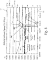
- FIG. 3 is a graph of a resonant frequency of a magnetostrictive resonator during exposure to an atmosphere having liquid-water content.
- graph 50 has horizontal axis 52 and two vertical axes 54, 56.
- Horizontal axis 52 is indicative of time.
- First vertical axis 54 is indicative of frequency of resonance of magnetostrictive resonator 14, and has units of Hz.
- Second vertical axis 56 is indicative of ambient temperature (e.g., atmospheric temperature), and has units of °C.
- Graph 50 has two relations 58, 60 plotted thereon.
- Relation 58 is indicative of the frequency of resonance of magnetostrictive resonator 14.
- Relation 60 is indicative of the temperature of the atmosphere in which magnetostrictive resonator 14 is located.
- the test logging began with the test already underway. From time equal to about zero through time equal to about 9:00, a non-zero liquid atmosphere is simulated using sprayed water.
- the resonant frequency throughout this portion of the testing is about 39,983 Hz.
- the temporal variation of the resonant frequency during this portion of the testing is about plus or minus 4 Hz.
- the resonant frequency of magnetostrictive resonator 14 is about 39,998 Hz. And during this portion of the testing the temporal variation of the resonant frequency is near zero.
- the magnitude of the temporal variations of the resonant frequency may be indicative of a mean liquid water droplet size.
- an ice/liquid water ratio may be determined using both the resonant frequency and the temporal variation of resonant frequency of the magnetostrictive resonator.
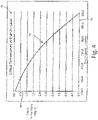
- FIG. 4 is a graph of a critical temperature vs. airspeed for a given angle of attack.
- graph 70 includes horizontal axis 72 and vertical axis 74.
- Horizontal axis 72 is indicative of airspeed of an aircraft.
- Vertical axis 74 is indicative of a critical temperature.
- Critical temperature is a temperature below which supercooled liquid-water droplets can begin to freeze on an exterior surface.
- Graph 70 shows critical temperature/airspeed relation 76.
- Critical temperature/airspeed relation 76 indicates that critical temperature decreases with increasing airspeed.
- Other aerodynamic factors can similarly affect critical temperature.
- angle of attack can affect critical temperature.
- Such graphs as exemplified by graph 70 of FIG. 4 , can be used to predict critical temperatures of various surface locations on an airplane.
- FIG. 5 is a block diagram of an exemplary cloud phase detection system.
- cloud phase detection system 18 includes magnetostrictive resonator 14 coupled to device 80 that can implement cloud phase detection.
- Device 80 can be any device capable of executing computer-readable instructions defining a software program implementing long-range cloud conditions detection. Examples of device 80 can include, but are not limited to, laptop computers, mobile phones (including smartphones), tablet computers, personal digital assistants (PDAs), desktop computers, servers, mainframes, or other computing devices.
- device 80 can be an avionics unit configured for use on an aerial vehicle, such as a helicopter, unmanned aerial vehicle (UAV), or other aircraft.
- UAV unmanned aerial vehicle
- device 80 includes processor 82, magnetostrictive resonator interface 84, communications module 86, storage system 88, input devices 90, output devices 92, and user interface 94.
- device 80 can include more or fewer components.
- device 80 may not include input device(s) 90 and/or output device(s) 92.
- device 80 may include additional components such as a battery that provides power to components of device 80 during operation.
- Processor(s) 82 are configured to implement functionality and/or process instructions for execution within device 80.
- processors) 82 can be capable of processing instructions stored in storage device(s) 88.
- Examples of processor(s) 82 can include any one or more of a microprocessor, a controller, a digital signal processor (DSP), an application specific integrated circuit (ASIC), a field-programmable gate array (FPGA), or other equivalent discrete or integrated logic circuitry.
- DSP digital signal processor
- ASIC application specific integrated circuit
- FPGA field-programmable gate array
- Storage device(s) 88 can be configured to store information within device 80 during operation.
- Storage device(s) 88 in some examples, are described as computer-readable storage media.
- a computer-readable storage medium can include a non-transitory medium.
- the term "non-transitory" can indicate that the storage medium is not embodied in a carrier wave or a propagated signal.
- a non-transitory storage medium can store data that can, over time, change (e.g., in RAM or cache).
- storage device(s) 88 are a temporary memory, meaning that a primary purpose of storage device(s) 88 is not long-term storage.
- Storage device(s) 88 in some examples, are described as volatile memory, meaning that storage device(s) 88 do not maintain stored contents when power to device 80 is turned off. Examples of volatile memories can include random access memories (RAM), dynamic random access memories (DRAM), static random access memories (SRAM), and other forms of volatile memories.
- RAM random access memories
- DRAM dynamic random access memories
- SRAM static random access memories
- storage device(s) 88 are used to store program instructions for execution by processor(s) 82.
- Storage device(s) 88 in one example, are used by software or applications running on device 80 (e.g., a software program implementing cloud phase detection) to temporarily store information during program execution.
- Storage device(s) 88 in some examples, also include one or more computer-readable storage media. Storage device(s) 88 can be configured to store larger amounts of information than volatile memory. Storage device(s) 88 can further be configured for long-term storage of information. In some examples, storage device(s) 88 include non-volatile storage elements. Examples of such non-volatile storage elements can include magnetic hard discs, optical discs, floppy discs, flash memories, or forms of electrically programmable memories (EPROM) or electrically erasable and programmable (EEPROM) memories. Storage device(s) 88 can include liquid-water detection segments 95, critical temperature calculator segment 97, and Ludlam temperature calculator segment 99.
- Device 80 also includes communications device(s) 86.
- Device 80 utilizes communication device(s) 86 to communicate with external devices via one or more networks, such as one or more wireless or wired networks or both.
- Communications device(s) 86 can be a network interface card, such as an Ethernet card, an optical transceiver, a radio frequency transceiver, or any other type of device that can send and receive information.
- network interfaces can include Bluetooth, 3G, 4G, and WiFi radio computing devices as well as Universal Serial Bus (USB).
- Device 80 also includes input device(s) 90.
- Input device(s) 90 are configured to receive input from a user.
- Examples of input device(s) 90 can include a mouse, a keyboard, a microphone, a camera device, a presence-sensitive and/or touch-sensitive display, or other type of device configured to receive input from a user.
- Output device(s) 92 can be configured to provide output to a user.
- Examples of output device(s) 92 can include a display device, a sound card, a video graphics card, a speaker, a cathode ray tube (CRT) monitor, a liquid crystal display (LCD), a light emitting diode (LED) display, an organic light emitting diode (OLED) display, or other type of device for outputting information in a form understandable to users or machines.
- device 80 illustrates one example embodiment of a device that can execute a software program including a plurality of segments that each includes one or more modules implementing an interface that enables direct communication between the respective module and modules that are members of any other of the plurality of segments.
- FIG. 6 is a flow chart of an exemplary method of detecting cloud conditions from a distance.
- method 100 is depicted from the vantage point of processor 82 of FIG. 5 .
- Method 100 begins at step 102 with processor 82 initializing index N to one, and establishing a baseline resonant frequency f R (BASELINE).
- processor 82 receives a measurement of the resonant frequency f R (N) of magnetostrictive resonator 14.
- processor 82 compares the mean resonant frequency f R with the baseline resonant frequency f R (BASELINE). If the mean resonant frequency f R is not less than the baseline resonant frequency f R (BASELINE), then method 100 proceeds to step 110 where processor 82 compares the calculated noise f N with a fraction (e.g., one ten-thousandth) of the baseline resonant frequency f R (BASELINE).
- step 110 If, at step 110, the calculated noise f N is not greater than the fraction of the baseline resonant frequency f R (BASELINE), then processor 82 increases index N and determines a liquid-water content of the cloud is zero. Method 100 then returns to step 104. If, however, either at step 108 or at step 110, the comparison was evaluated in the affirmative, then method 100 proceeds to step 114 where processor 82 increases index N and determines the liquid-water content is greater than zero. Then, method 100 again returns to step 104.
- various thresholds are used in the comparisons performed at steps 108 and 110.
- processor 82 compares mean resonant frequency f R with a product of baseline resonant frequency f R (BASELINE) and a factor less than 1.
- processor 82 may determine whether mean resonant frequency f R is at least one-ten thousandths of the baseline resonant frequency f R (BASELINE) less than the baseline resonant frequency f R (BASELINE).
- processor 82 may determine whether mean resonant frequency f R is at least three-ten thousandths of the baseline resonant frequency f R (BASELINE) less than the baseline resonant frequency f R (BASELINE) (e.g., less than 0.9997 times f R (BASELINE)). In some embodiments, processor 82 may compare calculated noise f N with various fractions of the baseline resonant frequency f R (BASELINE). For example, processor may compare f N with about one, two, three or about five ten-thousandths of the baseline resonant frequency f R (BASELINE).
Landscapes
- Chemical & Material Sciences (AREA)
- Physics & Mathematics (AREA)
- Health & Medical Sciences (AREA)
- Life Sciences & Earth Sciences (AREA)
- Engineering & Computer Science (AREA)
- Immunology (AREA)
- Pathology (AREA)
- Analytical Chemistry (AREA)
- Biochemistry (AREA)
- General Health & Medical Sciences (AREA)
- General Physics & Mathematics (AREA)
- Aviation & Aerospace Engineering (AREA)
- Food Science & Technology (AREA)
- Medicinal Chemistry (AREA)
- Combustion & Propulsion (AREA)
- Signal Processing (AREA)
- Electromagnetism (AREA)
- Acoustics & Sound (AREA)
- Chemical Kinetics & Catalysis (AREA)
- Electrochemistry (AREA)
- Measuring Temperature Or Quantity Of Heat (AREA)
Claims (13)
- Détecteur de phase de nuage comprenant :un résonateur magnétostrictif (14) configuré pour être fixé à un aéronef (10), le résonateur magnétostrictif (14) ayant une fréquence de résonance de base dans un état sans glace et sans eau liquide, le résonateur magnétostrictif (14) étant configuré pour résonner à une fréquence de résonance indicative d'une mesure d'accrétion de glace sur une surface extérieure du résonateur magnétostrictif (14) ; etun système de détection d'eau liquide configuré pour générer un signal indicatif de la teneur en eau liquide d'une surface d'aéronef, le système de détection d'eau liquide comprenant :un détecteur de fréquence configuré pour détecter la fréquence de résonance fR (N) du résonateur magnétostrictif (14) ;un détecteur de bruit configuré pour détecter des variations temporelles de la fréquence de résonance du résonateur magnétostrictif (14) ; etun processeur (82) configuré pour :calculer une fréquence de résonance moyenne courante
fR , en tant que valeur moyenne d'un certain nombre de dernières fréquences de résonance mesurées ;comparer la fréquence de résonance moyenne courantefR avec une fréquence de résonance de base établie ;calculer une variation temporelle de la fréquence de résonance fN 2= ΣN(fR (N) -fR )2 et une mesure de bruit fN ;comparer le bruit calculé fN de la fréquence de résonance à un seuil prédéterminé ;générer un signal indicatif de la teneur en eau liquide sur la surface d'aéronef, dans lequel le signal généré indicatif de la teneur en eau liquide est égal à zéro si la fréquence de résonance moyenne courante comparée n'est pas inférieure à la fréquence de résonance de base déterminée et le bruit comparé n'est pas supérieur au seuil prédéterminé, et dans lequel le signal généré indicatif de la teneur en eau liquide sur la surface d'aéronef est supérieur à zéro si le bruit comparé est supérieur au seuil prédéterminé. - Détecteur de phase de nuage selon la revendication 1, comprenant en outre :
un capteur de température configuré pour générer un signal indicatif de la température d'une surface extérieure du détecteur de phase de nuage. - Détecteur de phase de nuage selon la revendication 2, comprenant en outre :une interface de communication numérique configurée pour recevoir des communications numériques d'un bus d'instrumentation d'aéronef, les communications numériques reçues comportant un signal indicatif de la vitesse anémométrique d'un aéronef (10) et un signal indicatif d'un angle d'attaque de l'aéronef (10),dans lequel le système de détection d'eau liquide calcule, sur la base des signaux reçus de la vitesse anémométrique et de l'angle d'attaque ainsi que du signal indicatif de la température du nuage, une ou plusieurs températures critiques correspondant à un ou plusieurs emplacements de surface sur l'aéronef (10), respectivement, les une ou plusieurs températures critiques étant indicatives d'une température en dessous de laquelle une partie de la teneur en eau liquide peut geler sur l'emplacement de surface respectif, et de préférence dans lequel le système de détection d'eau liquide calcule, sur la base des signaux reçus de la vitesse anémométrique et de l'angle d'attaque ainsi que du signal indicatif de la température du nuage, une ou plusieurs températures Ludlam correspondant à un ou plusieurs emplacements de surface sur l'aéronef (10), respectivement, les une ou plusieurs températures Ludlam étant indicatives d'une température en dessous de laquelle toute la teneur en eau liquide peut geler sur l'emplacement de surface respectif.
- Détecteur de phase de nuage selon une quelconque revendication précédente, comprenant en outre un système de détection de phase de glace configuré pour générer un signal indicatif d'un taux de l'accrétion de glace, le signal étant indicatif du taux de l'accrétion de glace sur la base d'une pente de la fréquence de résonance mesurée par rapport au temps, et dans lequel le système de détection de phase de glace génère un signal indicatif de la teneur en eau liquide du nuage, le signal généré étant indicatif de la teneur en eau liquide sur la base de la pente de la fréquence de résonance mesurée par rapport au temps.
- Détecteur de phase de nuage selon une quelconque revendication précédente, dans lequel le système de détection d'eau liquide est configuré pour générer un signal indicatif de la teneur en eau liquide si la fréquence de résonance détectée est d'au moins trois dix-millièmes de la fréquence de résonance de base inférieure à la fréquence de résonance de base et les variations temporelles détectées de la fréquence de résonance sont supérieures au seuil prédéterminé, le seuil prédéterminé étant égal à deux dix-millièmes de la fréquence de résonance de base.
- Détecteur de phase de nuage selon la revendication 1, comprenant en outre :un détecteur de température ambiante configuré pour générer un signal indicatif d'une température ambiante ;un anémomètre configuré pour détecter la vitesse anémométrique d'un aéronef (10) ;un capteur d'angle d'attaque configuré pour détecter un angle d'attaque de l'aéronef (10) ; etun calculateur de température critique (97) configuré pour calculer, sur la base de la vitesse anémométrique détectée, de l'angle d'attaque détecté, de la température ambiante détectée, de la fréquence de résonance détectée et des variations temporelles détectées de la fréquence de résonance, une ou plusieurs températures critiques correspondant à un ou plusieurs emplacements sur une surface d'aéronef, respectivement, les une ou plusieurs températures critiques étant indicatives d'une température en dessous de laquelle une fraction de congélation de la teneur en eau liquide est supérieure à zéro.
- Détecteur de phase de nuage selon la revendication 6, dans lequel le système de détection d'eau liquide calcule, sur la base des signaux reçus de la vitesse anémométrique et de l'angle d'attaque ainsi que du signal indicatif de la température du nuage, une ou plusieurs températures Ludlam correspondant à un ou plusieurs emplacements de surface sur l'aéronef, respectivement, les une ou plusieurs températures Ludlam indiquant une température en dessous de laquelle toute la teneur en eau liquide peut geler sur l'emplacement de surface respectif.
- Détecteur de phase de nuage selon la revendication 7, dans lequel le système de détection d'eau liquide est configuré pour générer un signal indicatif de la teneur en eau liquide si à la fois la fréquence de résonance détectée est inférieure à la fréquence de résonance de base et les variations temporelles détectées de la fréquence de résonance sont supérieures au seuil prédéterminé, le seuil prédéterminé étant égal à un dix-millième de la fréquence de résonance de base.
- Détecteur de phase de nuage selon la revendication 6, 7 ou 8, dans lequel le système de détection d'eau liquide génère un signal indicatif d'un taux de l'accrétion de glace, le signal étant indicatif du taux de l'accrétion de glace sur la base d'une pente de la fréquence de résonance mesurée par rapport au temps, et de préférence dans lequel le système de détection d'eau liquide génère un signal indicatif de la teneur en eau si la pente de la fréquence de résonance mesurée est inférieure au seuil prédéterminé.
- Procédé pour déterminer la teneur en eau liquide sur une surface d'aéronef, le procédé comportant :la fixation d'un résonateur (14) à un aéronef (10) ;la résonance magnétostrictive du résonateur (14) ;la détermination d'une fréquence de résonance de base du résonateur (14) ;la mesure d'une fréquence de résonance fR (N) du résonateur (14) dans le nuage ;le calcul d'une fréquence de résonance moyenne courante
fR ;la comparaison de la fréquence de résonance moyenne courantefR avec la fréquence de résonance de base déterminée ;la détermination d'une variation temporelle de la fréquence de résonance mesurée fN 2= ΣN(fR (N)-fR )2 et d'une mesure de bruit fN ;la comparaison du bruit déterminé de la fréquence de résonance mesurée avec un seuil prédéterminé ;la génération d'un signal indicatif de la teneur en eau liquide sur la surface d'aéronef, dans lequel le signal généré indicatif de la teneur en eau liquide est égal à zéro si la fréquence de résonance comparée n'est pas inférieure à la fréquence de résonance de base déterminée et le bruit comparé n'est pas supérieur au seuil prédéterminé, et dans lequel le signal généré indicatif de la teneur en eau liquide sur la surface d'aéronef est supérieur à zéro si le bruit comparé est supérieur au seuil prédéterminé. - Procédé selon la revendication 10, dans lequel le seuil prédéterminé est d'au moins trois dix-millièmes de la fréquence de résonance de base.
- Procédé selon la revendication 9, 10 ou 11, comprenant en outre :
la génération d'un signal indicatif de la température ambiante. - Procédé selon la revendication 12, comprenant en outre :la détection de la vitesse anémométrique d'un aéronef (10) ; etla détection d'un angle d'attaque de l'aéronef (10) ; etcomprenant en outre :
le calcul, sur la base de la vitesse anémométrique détectée, de l'angle d'attaque détecté, de la température ambiante détectée, de la fréquence de résonance détectée et des variations temporelles détectées de la fréquence de résonance, d'une ou de plusieurs températures critiques correspondant à un ou plusieurs emplacements sur une surface d'aéronef, respectivement, les une ou plusieurs températures critiques étant indicatives d'une température en dessous de laquelle une fraction de congélation de la teneur en eau est supérieure à zéro.
Applications Claiming Priority (2)
| Application Number | Priority Date | Filing Date | Title |
|---|---|---|---|
| US201662328984P | 2016-04-28 | 2016-04-28 | |
| US15/423,296 US10343783B2 (en) | 2016-04-28 | 2017-02-02 | Method and apparatus of detecting liquid water in a cloud |
Publications (2)
| Publication Number | Publication Date |
|---|---|
| EP3243752A1 EP3243752A1 (fr) | 2017-11-15 |
| EP3243752B1 true EP3243752B1 (fr) | 2022-06-01 |
Family
ID=58772313
Family Applications (1)
| Application Number | Title | Priority Date | Filing Date |
|---|---|---|---|
| EP17168306.3A Active EP3243752B1 (fr) | 2016-04-28 | 2017-04-26 | Procédé et appareil de détection d'eau liquide dans un nuage par un résonateur magnetostrictif |
Country Status (3)
| Country | Link |
|---|---|
| US (1) | US10343783B2 (fr) |
| EP (1) | EP3243752B1 (fr) |
| CA (1) | CA2964259C (fr) |
Families Citing this family (4)
| Publication number | Priority date | Publication date | Assignee | Title |
|---|---|---|---|---|
| US10435161B1 (en) * | 2018-05-02 | 2019-10-08 | Rosemount Aerospace Inc. | Surface sensing for droplet size differentiation |
| CN112782211B (zh) * | 2020-12-28 | 2023-11-21 | 东北电力大学 | 一种水相变的探测方法 |
| US11912419B2 (en) | 2022-01-21 | 2024-02-27 | Honeywell International Inc. | Ice protection modulation with atmospheric conditions |
| US20230408242A1 (en) * | 2022-06-17 | 2023-12-21 | Rosemount Aerospace Inc. | Additive material integrated heater deposited or embedded within an ice detector |
Family Cites Families (15)
| Publication number | Priority date | Publication date | Assignee | Title |
|---|---|---|---|---|
| US3341835A (en) * | 1964-11-05 | 1967-09-12 | Rosemount Eng Co Ltd | Ice detector |
| US3508435A (en) * | 1966-08-25 | 1970-04-28 | Leon Harlan Ivy | Moisture measuring system |
| CH467568A (de) * | 1966-12-20 | 1969-01-15 | Hans Grieshaber & Co | Elektroakustischer Wandler |
| JPS5712329A (en) | 1980-06-25 | 1982-01-22 | Hitachi Ltd | Frost sensor |
| US6560551B1 (en) | 2000-08-18 | 2003-05-06 | Rosemount Aerospace Inc. | Liquid water content measurement apparatus and method |
| US6320511B1 (en) | 2000-11-28 | 2001-11-20 | Rosemount Aerospace Inc. | Ice detector configuration for improved ice detection at near freezing conditions |
| AU2003228683A1 (en) * | 2002-04-25 | 2003-11-10 | Glaxo Group Limited | Magnetoacoustic sensor system and associated method for sensing environmental conditions |
| US7438944B2 (en) * | 2003-07-11 | 2008-10-21 | Seiko Epson Corporation | Droplet information measuring method and apparatus therefor, film pattern forming method, device manufacturing method, droplet discharge apparatus, electro-optical apparatus, and electronic apparatus |
| US7302829B2 (en) * | 2003-12-01 | 2007-12-04 | General Electric Company | Contactless humidity/chemical vapor sensor device and associated method of fabrication |
| US20050230553A1 (en) * | 2004-03-31 | 2005-10-20 | Rosemount Aerospace Inc. | Ice detector for improved ice detection at near freezing condition |
| US20050262943A1 (en) * | 2004-05-27 | 2005-12-01 | Glenn Claydon | Apparatus, methods, and systems to detect an analyte based on changes in a resonant frequency of a spring element |
| JP2011034809A (ja) * | 2009-07-31 | 2011-02-17 | Sanyo Electric Co Ltd | 生成水除去装置 |
| US10513340B2 (en) * | 2012-08-02 | 2019-12-24 | Rosemount Aerospace Inc. | Rotor ice protection systems and methods |
| US9242735B1 (en) | 2014-08-28 | 2016-01-26 | The Boeing Company | Detecting inflight icing conditions on aircraft |
| US10099791B2 (en) * | 2015-07-28 | 2018-10-16 | Fbs, Inc. | Magnetostrictive multi-frequency guided wave ice sensing probe |
-
2017
- 2017-02-02 US US15/423,296 patent/US10343783B2/en active Active
- 2017-04-11 CA CA2964259A patent/CA2964259C/fr active Active
- 2017-04-26 EP EP17168306.3A patent/EP3243752B1/fr active Active
Also Published As
| Publication number | Publication date |
|---|---|
| CA2964259A1 (fr) | 2017-10-28 |
| EP3243752A1 (fr) | 2017-11-15 |
| BR102017008645A2 (pt) | 2017-10-31 |
| US20170313429A1 (en) | 2017-11-02 |
| US10343783B2 (en) | 2019-07-09 |
| CA2964259C (fr) | 2023-08-29 |
Similar Documents
| Publication | Publication Date | Title |
|---|---|---|
| EP3243752B1 (fr) | Procédé et appareil de détection d'eau liquide dans un nuage par un résonateur magnetostrictif | |
| US10124901B2 (en) | Icing condition detection method | |
| EP2800690B1 (fr) | Système de détection d'une condition de givrage à grosses gouttes surfondues | |
| CA2800449C (fr) | Systeme de detection au laser d'une condition de givrage a grosses gouttes surfondues | |
| EP2636599B1 (fr) | Système de détection d'état de givrage de goutte d'eau de grande taille en surfusion | |
| US10435161B1 (en) | Surface sensing for droplet size differentiation | |
| EP3783333B1 (fr) | Caractérisation d'une atmosphère de nuage au moyen d'une lumière rétrodiffusée à deux angles | |
| EP3263459B1 (fr) | Différenciation de taille de gouttelettes d'eau super refroidie automatisée au moyen de motifs d'accrétion d'aéronef | |
| EP3398855B1 (fr) | Localisateur de limite d'accrétion de glace | |
| EP3263460B1 (fr) | Différenciation de taille de gouttelettes d'eau super refroidie automatisée au moyen de motifs d'accrétion d'aéronef | |
| US20180111694A1 (en) | Super-cooled water-droplet size indicator | |
| BR102017008645B1 (pt) | Detector de fase de nuvem, calculador de teor de água líquida, e, método para determinar teor de água líquida numa nuvem |
Legal Events
| Date | Code | Title | Description |
|---|---|---|---|
| PUAI | Public reference made under article 153(3) epc to a published international application that has entered the european phase |
Free format text: ORIGINAL CODE: 0009012 |
|
| STAA | Information on the status of an ep patent application or granted ep patent |
Free format text: STATUS: THE APPLICATION HAS BEEN PUBLISHED |
|
| AK | Designated contracting states |
Kind code of ref document: A1 Designated state(s): AL AT BE BG CH CY CZ DE DK EE ES FI FR GB GR HR HU IE IS IT LI LT LU LV MC MK MT NL NO PL PT RO RS SE SI SK SM TR |
|
| AX | Request for extension of the european patent |
Extension state: BA ME |
|
| STAA | Information on the status of an ep patent application or granted ep patent |
Free format text: STATUS: REQUEST FOR EXAMINATION WAS MADE |
|
| 17P | Request for examination filed |
Effective date: 20180515 |
|
| RBV | Designated contracting states (corrected) |
Designated state(s): AL AT BE BG CH CY CZ DE DK EE ES FI FR GB GR HR HU IE IS IT LI LT LU LV MC MK MT NL NO PL PT RO RS SE SI SK SM TR |
|
| STAA | Information on the status of an ep patent application or granted ep patent |
Free format text: STATUS: EXAMINATION IS IN PROGRESS |
|
| 17Q | First examination report despatched |
Effective date: 20190514 |
|
| STAA | Information on the status of an ep patent application or granted ep patent |
Free format text: STATUS: EXAMINATION IS IN PROGRESS |
|
| GRAP | Despatch of communication of intention to grant a patent |
Free format text: ORIGINAL CODE: EPIDOSNIGR1 |
|
| STAA | Information on the status of an ep patent application or granted ep patent |
Free format text: STATUS: GRANT OF PATENT IS INTENDED |
|
| GRAS | Grant fee paid |
Free format text: ORIGINAL CODE: EPIDOSNIGR3 |
|
| INTG | Intention to grant announced |
Effective date: 20220315 |
|
| GRAA | (expected) grant |
Free format text: ORIGINAL CODE: 0009210 |
|
| STAA | Information on the status of an ep patent application or granted ep patent |
Free format text: STATUS: THE PATENT HAS BEEN GRANTED |
|
| AK | Designated contracting states |
Kind code of ref document: B1 Designated state(s): AL AT BE BG CH CY CZ DE DK EE ES FI FR GB GR HR HU IE IS IT LI LT LU LV MC MK MT NL NO PL PT RO RS SE SI SK SM TR |
|
| REG | Reference to a national code |
Ref country code: GB Ref legal event code: FG4D |
|
| REG | Reference to a national code |
Ref country code: AT Ref legal event code: REF Ref document number: 1495239 Country of ref document: AT Kind code of ref document: T Effective date: 20220615 Ref country code: CH Ref legal event code: EP |
|
| REG | Reference to a national code |
Ref country code: IE Ref legal event code: FG4D |
|
| REG | Reference to a national code |
Ref country code: DE Ref legal event code: R096 Ref document number: 602017057937 Country of ref document: DE |
|
| REG | Reference to a national code |
Ref country code: LT Ref legal event code: MG9D |
|
| REG | Reference to a national code |
Ref country code: NL Ref legal event code: MP Effective date: 20220601 |
|
| PG25 | Lapsed in a contracting state [announced via postgrant information from national office to epo] |
Ref country code: SE Free format text: LAPSE BECAUSE OF FAILURE TO SUBMIT A TRANSLATION OF THE DESCRIPTION OR TO PAY THE FEE WITHIN THE PRESCRIBED TIME-LIMIT Effective date: 20220601 Ref country code: NO Free format text: LAPSE BECAUSE OF FAILURE TO SUBMIT A TRANSLATION OF THE DESCRIPTION OR TO PAY THE FEE WITHIN THE PRESCRIBED TIME-LIMIT Effective date: 20220901 Ref country code: LT Free format text: LAPSE BECAUSE OF FAILURE TO SUBMIT A TRANSLATION OF THE DESCRIPTION OR TO PAY THE FEE WITHIN THE PRESCRIBED TIME-LIMIT Effective date: 20220601 Ref country code: HR Free format text: LAPSE BECAUSE OF FAILURE TO SUBMIT A TRANSLATION OF THE DESCRIPTION OR TO PAY THE FEE WITHIN THE PRESCRIBED TIME-LIMIT Effective date: 20220601 Ref country code: GR Free format text: LAPSE BECAUSE OF FAILURE TO SUBMIT A TRANSLATION OF THE DESCRIPTION OR TO PAY THE FEE WITHIN THE PRESCRIBED TIME-LIMIT Effective date: 20220902 Ref country code: FI Free format text: LAPSE BECAUSE OF FAILURE TO SUBMIT A TRANSLATION OF THE DESCRIPTION OR TO PAY THE FEE WITHIN THE PRESCRIBED TIME-LIMIT Effective date: 20220601 Ref country code: ES Free format text: LAPSE BECAUSE OF FAILURE TO SUBMIT A TRANSLATION OF THE DESCRIPTION OR TO PAY THE FEE WITHIN THE PRESCRIBED TIME-LIMIT Effective date: 20220601 Ref country code: BG Free format text: LAPSE BECAUSE OF FAILURE TO SUBMIT A TRANSLATION OF THE DESCRIPTION OR TO PAY THE FEE WITHIN THE PRESCRIBED TIME-LIMIT Effective date: 20220901 |
|
| REG | Reference to a national code |
Ref country code: AT Ref legal event code: MK05 Ref document number: 1495239 Country of ref document: AT Kind code of ref document: T Effective date: 20220601 |
|
| PG25 | Lapsed in a contracting state [announced via postgrant information from national office to epo] |
Ref country code: RS Free format text: LAPSE BECAUSE OF FAILURE TO SUBMIT A TRANSLATION OF THE DESCRIPTION OR TO PAY THE FEE WITHIN THE PRESCRIBED TIME-LIMIT Effective date: 20220601 Ref country code: PL Free format text: LAPSE BECAUSE OF FAILURE TO SUBMIT A TRANSLATION OF THE DESCRIPTION OR TO PAY THE FEE WITHIN THE PRESCRIBED TIME-LIMIT Effective date: 20220601 Ref country code: LV Free format text: LAPSE BECAUSE OF FAILURE TO SUBMIT A TRANSLATION OF THE DESCRIPTION OR TO PAY THE FEE WITHIN THE PRESCRIBED TIME-LIMIT Effective date: 20220601 |
|
| PG25 | Lapsed in a contracting state [announced via postgrant information from national office to epo] |
Ref country code: NL Free format text: LAPSE BECAUSE OF FAILURE TO SUBMIT A TRANSLATION OF THE DESCRIPTION OR TO PAY THE FEE WITHIN THE PRESCRIBED TIME-LIMIT Effective date: 20220601 |
|
| PG25 | Lapsed in a contracting state [announced via postgrant information from national office to epo] |
Ref country code: SM Free format text: LAPSE BECAUSE OF FAILURE TO SUBMIT A TRANSLATION OF THE DESCRIPTION OR TO PAY THE FEE WITHIN THE PRESCRIBED TIME-LIMIT Effective date: 20220601 Ref country code: SK Free format text: LAPSE BECAUSE OF FAILURE TO SUBMIT A TRANSLATION OF THE DESCRIPTION OR TO PAY THE FEE WITHIN THE PRESCRIBED TIME-LIMIT Effective date: 20220601 Ref country code: RO Free format text: LAPSE BECAUSE OF FAILURE TO SUBMIT A TRANSLATION OF THE DESCRIPTION OR TO PAY THE FEE WITHIN THE PRESCRIBED TIME-LIMIT Effective date: 20220601 Ref country code: PT Free format text: LAPSE BECAUSE OF FAILURE TO SUBMIT A TRANSLATION OF THE DESCRIPTION OR TO PAY THE FEE WITHIN THE PRESCRIBED TIME-LIMIT Effective date: 20221003 Ref country code: EE Free format text: LAPSE BECAUSE OF FAILURE TO SUBMIT A TRANSLATION OF THE DESCRIPTION OR TO PAY THE FEE WITHIN THE PRESCRIBED TIME-LIMIT Effective date: 20220601 Ref country code: CZ Free format text: LAPSE BECAUSE OF FAILURE TO SUBMIT A TRANSLATION OF THE DESCRIPTION OR TO PAY THE FEE WITHIN THE PRESCRIBED TIME-LIMIT Effective date: 20220601 Ref country code: AT Free format text: LAPSE BECAUSE OF FAILURE TO SUBMIT A TRANSLATION OF THE DESCRIPTION OR TO PAY THE FEE WITHIN THE PRESCRIBED TIME-LIMIT Effective date: 20220601 |
|
| PG25 | Lapsed in a contracting state [announced via postgrant information from national office to epo] |
Ref country code: IS Free format text: LAPSE BECAUSE OF FAILURE TO SUBMIT A TRANSLATION OF THE DESCRIPTION OR TO PAY THE FEE WITHIN THE PRESCRIBED TIME-LIMIT Effective date: 20221001 |
|
| REG | Reference to a national code |
Ref country code: DE Ref legal event code: R097 Ref document number: 602017057937 Country of ref document: DE |
|
| REG | Reference to a national code |
Ref country code: FR Ref legal event code: PLFP Year of fee payment: 7 |
|
| PG25 | Lapsed in a contracting state [announced via postgrant information from national office to epo] |
Ref country code: AL Free format text: LAPSE BECAUSE OF FAILURE TO SUBMIT A TRANSLATION OF THE DESCRIPTION OR TO PAY THE FEE WITHIN THE PRESCRIBED TIME-LIMIT Effective date: 20220601 |
|
| PLBE | No opposition filed within time limit |
Free format text: ORIGINAL CODE: 0009261 |
|
| STAA | Information on the status of an ep patent application or granted ep patent |
Free format text: STATUS: NO OPPOSITION FILED WITHIN TIME LIMIT |
|
| PG25 | Lapsed in a contracting state [announced via postgrant information from national office to epo] |
Ref country code: DK Free format text: LAPSE BECAUSE OF FAILURE TO SUBMIT A TRANSLATION OF THE DESCRIPTION OR TO PAY THE FEE WITHIN THE PRESCRIBED TIME-LIMIT Effective date: 20220601 |
|
| PGFP | Annual fee paid to national office [announced via postgrant information from national office to epo] |
Ref country code: FR Payment date: 20230321 Year of fee payment: 7 |
|
| 26N | No opposition filed |
Effective date: 20230302 |
|
| PG25 | Lapsed in a contracting state [announced via postgrant information from national office to epo] |
Ref country code: SI Free format text: LAPSE BECAUSE OF FAILURE TO SUBMIT A TRANSLATION OF THE DESCRIPTION OR TO PAY THE FEE WITHIN THE PRESCRIBED TIME-LIMIT Effective date: 20220601 |
|
| PGFP | Annual fee paid to national office [announced via postgrant information from national office to epo] |
Ref country code: DE Payment date: 20230321 Year of fee payment: 7 |
|
| REG | Reference to a national code |
Ref country code: CH Ref legal event code: PL |
|
| PG25 | Lapsed in a contracting state [announced via postgrant information from national office to epo] |
Ref country code: LU Free format text: LAPSE BECAUSE OF NON-PAYMENT OF DUE FEES Effective date: 20230426 |
|
| REG | Reference to a national code |
Ref country code: BE Ref legal event code: MM Effective date: 20230430 |
|
| PG25 | Lapsed in a contracting state [announced via postgrant information from national office to epo] |
Ref country code: MC Free format text: LAPSE BECAUSE OF FAILURE TO SUBMIT A TRANSLATION OF THE DESCRIPTION OR TO PAY THE FEE WITHIN THE PRESCRIBED TIME-LIMIT Effective date: 20220601 |
|
| PG25 | Lapsed in a contracting state [announced via postgrant information from national office to epo] |
Ref country code: MC Free format text: LAPSE BECAUSE OF FAILURE TO SUBMIT A TRANSLATION OF THE DESCRIPTION OR TO PAY THE FEE WITHIN THE PRESCRIBED TIME-LIMIT Effective date: 20220601 Ref country code: LI Free format text: LAPSE BECAUSE OF NON-PAYMENT OF DUE FEES Effective date: 20230430 Ref country code: IT Free format text: LAPSE BECAUSE OF FAILURE TO SUBMIT A TRANSLATION OF THE DESCRIPTION OR TO PAY THE FEE WITHIN THE PRESCRIBED TIME-LIMIT Effective date: 20220601 Ref country code: CH Free format text: LAPSE BECAUSE OF NON-PAYMENT OF DUE FEES Effective date: 20230430 |
|
| REG | Reference to a national code |
Ref country code: IE Ref legal event code: MM4A |
|
| PG25 | Lapsed in a contracting state [announced via postgrant information from national office to epo] |
Ref country code: BE Free format text: LAPSE BECAUSE OF NON-PAYMENT OF DUE FEES Effective date: 20230430 |
|
| PG25 | Lapsed in a contracting state [announced via postgrant information from national office to epo] |
Ref country code: IE Free format text: LAPSE BECAUSE OF NON-PAYMENT OF DUE FEES Effective date: 20230426 |
|
| PG25 | Lapsed in a contracting state [announced via postgrant information from national office to epo] |
Ref country code: IE Free format text: LAPSE BECAUSE OF NON-PAYMENT OF DUE FEES Effective date: 20230426 |
|
| PGFP | Annual fee paid to national office [announced via postgrant information from national office to epo] |
Ref country code: GB Payment date: 20240320 Year of fee payment: 8 |