EP3243681A1 - Flip up cap - Google Patents
Flip up cap Download PDFInfo
- Publication number
- EP3243681A1 EP3243681A1 EP17171723.4A EP17171723A EP3243681A1 EP 3243681 A1 EP3243681 A1 EP 3243681A1 EP 17171723 A EP17171723 A EP 17171723A EP 3243681 A1 EP3243681 A1 EP 3243681A1
- Authority
- EP
- European Patent Office
- Prior art keywords
- pivotal
- pivotal member
- closure device
- body portion
- protruding position
- Prior art date
- Legal status (The legal status is an assumption and is not a legal conclusion. Google has not performed a legal analysis and makes no representation as to the accuracy of the status listed.)
- Granted
Links
Images


Classifications
-
- B—PERFORMING OPERATIONS; TRANSPORTING
- B60—VEHICLES IN GENERAL
- B60K—ARRANGEMENT OR MOUNTING OF PROPULSION UNITS OR OF TRANSMISSIONS IN VEHICLES; ARRANGEMENT OR MOUNTING OF PLURAL DIVERSE PRIME-MOVERS IN VEHICLES; AUXILIARY DRIVES FOR VEHICLES; INSTRUMENTATION OR DASHBOARDS FOR VEHICLES; ARRANGEMENTS IN CONNECTION WITH COOLING, AIR INTAKE, GAS EXHAUST OR FUEL SUPPLY OF PROPULSION UNITS IN VEHICLES
- B60K15/00—Arrangement in connection with fuel supply of combustion engines or other fuel consuming energy converters, e.g. fuel cells; Mounting or construction of fuel tanks
- B60K15/03—Fuel tanks
- B60K15/04—Tank inlets
- B60K15/0406—Filler caps for fuel tanks
-
- B—PERFORMING OPERATIONS; TRANSPORTING
- B60—VEHICLES IN GENERAL
- B60K—ARRANGEMENT OR MOUNTING OF PROPULSION UNITS OR OF TRANSMISSIONS IN VEHICLES; ARRANGEMENT OR MOUNTING OF PLURAL DIVERSE PRIME-MOVERS IN VEHICLES; AUXILIARY DRIVES FOR VEHICLES; INSTRUMENTATION OR DASHBOARDS FOR VEHICLES; ARRANGEMENTS IN CONNECTION WITH COOLING, AIR INTAKE, GAS EXHAUST OR FUEL SUPPLY OF PROPULSION UNITS IN VEHICLES
- B60K15/00—Arrangement in connection with fuel supply of combustion engines or other fuel consuming energy converters, e.g. fuel cells; Mounting or construction of fuel tanks
- B60K15/03—Fuel tanks
- B60K15/04—Tank inlets
- B60K15/0406—Filler caps for fuel tanks
- B60K2015/0432—Filler caps for fuel tanks having a specific connection between the cap and the vehicle or tank opening
- B60K2015/0445—Filler caps for fuel tanks having a specific connection between the cap and the vehicle or tank opening using hinges
Definitions
- Most of the conventional closure devices provide an unfavorable grip to an operator. Also, a portion of the cap that protrudes outwardly when the cap is in the closed position is used for gripping by the operator. Moreover, caps with an openable gripping portion are also used in the handheld tools. The openable gripping portion may be opened to provide a better grip to the operator while releasing or tightening of the cap. These caps may be better than the conventional caps, however, they suffer from the problem of unintended opening of the openable gripping portion. The unintended opening of the openable gripping portion may result in breaking of the cap or unintended releasing of the cap.
- a closure device for a tank such as, but not limited to, a fuel tank or a lubricant tank of the handheld tool. Moreover, there exists a need for the closure device which provides a better grip to an operator while releasing or tightening of a cap.
- a threshold position is arranged for the pivotal member between the retracted position and the protruding position, and for a position of the pivotal member between the threshold position and the protruding position, the resilient member urges the pivotal member towards the protruding position.
- the resilient member may be a spring attached in one end to the pivotal member and in another end to the body portion.
- the resilient member may be a conical pressure spring.
- the pivotal member may be pivotal about or with at least one pin, which at least one pin may be secured to the body portion.
- the biasing member may be a torsion spring arranged around said at least one pin for urging the pivotal member to return to the retracted position.
- the grip portion may extend a distance A from the pivotal axis and the counter portion may extend at least a distance of 0.25 A, and preferably at least 0.35 A, and even more preferably at least 0.45 A from the pivotal axis.
- the counter portion may not be too small when the operator needs to push on the counter portion to lift the grip portion of the pivotal member. If the extension of the counter portion is too small, the area of the counter portion surface would be too small for the operator to push, and also the amount force needed to push the counter portion to lift the grip portion would be too large.
- FIG. 2 illustrates a perspective view of the closure device 2.
- the closure device 2 includes a body portion 20 provided with threads 4 for engagement with corresponding threads of the refill opening.
- the refill opening may be closed by tightening the body portion 20 of the closure device 2 into the refill opening of the fuel tank of the handheld power tool 1.
- the closure device 2 has a substantially flat top surface.
- the closure device 2 further includes a skirt 5 to provide a fluid-tight seal when the closure device 2 is fully engaged into the refill opening.
Landscapes
- Engineering & Computer Science (AREA)
- Transportation (AREA)
- Sustainable Development (AREA)
- Sustainable Energy (AREA)
- Chemical & Material Sciences (AREA)
- Combustion & Propulsion (AREA)
- Life Sciences & Earth Sciences (AREA)
- Mechanical Engineering (AREA)
- Closures For Containers (AREA)
- Lock And Its Accessories (AREA)
- Closing And Opening Devices For Wings, And Checks For Wings (AREA)
- Portable Power Tools In General (AREA)
- Cooling, Air Intake And Gas Exhaust, And Fuel Tank Arrangements In Propulsion Units (AREA)
Abstract
Description
- The present invention relates to a closure device for a tank such as a fuel tank or a lubricant tank. More particularly, it relates to a closure device for the tank of a portable handheld tool.
- Internal combustion engines are widely used in a variety of handheld tools such as, but not limited to, chainsaw, hedge trimmer, grass trimmer, blower, mower, and the like. The engine driven handheld tools are provided with a tank such as a fuel tank or a lubricant tank with a refill opening. Typical closure device for the threaded fill opening of the tank may include a threaded cap which is engageable with the corresponding threads in the refill opening. The threaded cap closes off the refill opening tightly with respect to the ambient by tightening the cap in the refill opening.
- Most of the conventional closure devices provide an unfavorable grip to an operator. Also, a portion of the cap that protrudes outwardly when the cap is in the closed position is used for gripping by the operator. Moreover, caps with an openable gripping portion are also used in the handheld tools. The openable gripping portion may be opened to provide a better grip to the operator while releasing or tightening of the cap. These caps may be better than the conventional caps, however, they suffer from the problem of unintended opening of the openable gripping portion. The unintended opening of the openable gripping portion may result in breaking of the cap or unintended releasing of the cap.
- Therefore, there exists a need for a closure device for a tank such as, but not limited to, a fuel tank or a lubricant tank of the handheld tool. Moreover, there exists a need for the closure device which provides a better grip to an operator while releasing or tightening of a cap.
- In view of the above, it is an objective to solve or at least reduce the problems discussed above. In particular, an objective is to provide a means for closing the refill opening of a tank such as a fuel tank or a lubricant tank of a handheld power tool. The closing means may be opened to provide a convenient grip to an operator.
- The objective is achieved by a closure device for closing a refill opening of a tank in a handheld power tool described in claim 1. The closure device comprises a body portion and a pivotal member. The body portion is configured to engage the refill opening. The pivotal member is configured to pivot about a pivotal axis and pivotally connected to the body portion for movement between a retracted position and a protruding position. The pivotal member includes a grip portion that in the protruding position extends away from the body portion to form a grip. This helps an operator in loosening and tightening of the closure device. The body portion may define a longitudinal axis.
- The closure device may provide the pivotal member to be lockable in the protruding position by means of a holding member, wherein a first part of the holding member may be secured to the pivotal member and a second part of the holding member may be secured to the body portion. The closure device may further comprise a biasing member arranged for urging the pivotal member towards the retracted position.
- With such a closure device the tightening and loosening of the closure device is facilitated by the protruding grip portion. It is easy to use for the operator even if he or she for instance is wearing gloves, since the grip portion may be locked in the protruding position when the tank is being opened or closed.
- The closure device may provide a smooth outer surface automatically when the pivotal member is not in the protruding position. Also, when operating the power tool, if something, for instance a branch or the like, would hook on to the pivotal member, the pivotal member will be urged towards the retracted position again when the branch let the pivotal member go. If the pivotal member instead would stay in a position separated from the retracted position there would be a risk of the closure device to be damaged, or unintended loosening of the closure device to occur. The body may be provided with threads for engagement with corresponding threads on the refill opening. The body portion and the refill opening may also, in another embodiment, be provided with other engagement means than threads, such as means for a bayonet coupling, snapping means or the like.
- According to an embodiment, the holding member comprises a first fastening member attached to the pivotal member and a second fastening member attached to the body portion. The first and the second fastening members are adapted to engage each other when the pivotal member is in the protruding position.
- The fastening members may be arranged for engaging each other when the operator moves the pivotal member to the protruding position. In that way, an amount of torque may be needed to move the pivotal member to the lockable protruding position such that a branch that may hook on to the pivotal member would not be able to move the pivotal member to the lockable protruding position. The fastening members may also provide a strong holding function for the pivotal member in the protruding position when the operator looses or tightens the closure device. The amount of torque needed for releasing the fastening members from each other may be greater than the amount of torque provided by the biasing member when urging the pivotal member towards the retracted position.
- In a further embodiment, the holding member may be a resilient member.
- Thereby, the resilience of the member may set the amount of force needed for moving the pivotal member to the lockable protruding position.
- In a further embodiment, a threshold position is arranged for the pivotal member between the retracted position and the protruding position, and for a position of the pivotal member between the threshold position and the protruding position, the resilient member urges the pivotal member towards the protruding position.
- By urging the pivotal member towards the protruding position the protruding position may easier be reached when moving the pivotal member. The pivotal member is held in the protruding position by the resilient member constantly urging the pivotal member towards the protruding position, until an operator moves the pivotal member passed the threshold position.
- In another embodiment, the resilient member may be a spring attached in one end to the pivotal member and in another end to the body portion. In yet another embodiment, the resilient member may be a conical pressure spring.
- By providing a spring as the resilient member, the spring may provide the urging function on the pivotal member towards the protruding position when the pivotal member is in a position between the threshold position and the protruding position. When the pivotal member is in the protruding position, the spring may hold the pivotal member in the protruding position by spring force.
- In a further embodiment, the biasing member is the same as the resilient member, and for a position of the pivotal member between the threshold position and the retracted position, the resilient member urges the pivotal member towards the retracted position.
- This may be provided when the resilient member is a spring attached to the pivotal member and the body portion. When the pivotal member is on one side of the threshold position, the spring may urge the pivotal member towards the retracted position. When the pivotal member is on the other side of the threshold position, the spring may urge the pivotal member towards the protruding position and then hold the pivotal member in the protruding position, facilitating the grip for the operator when loosening or tightening the closure device. The construction of the closure device may be simpler and more cost-effective when the same member urges the pivotal member to both the retracted and the protruding position. The location of the threshold position may be set by the design of the spring and the pivotal member. Also the torque needed for moving the pivotal member to or from the protruding position may be set by the spring force.
- According to a further embodiment, the pivotal member may be pivotal about or with at least one pin, which at least one pin may be secured to the body portion. In this case the biasing member may be a torsion spring arranged around said at least one pin for urging the pivotal member to return to the retracted position.
- The torsion spring may provide the urging function of the pivotal member towards the retracted position when the holding member or the resilient member not provides such urging. Thereby, the pivotal member may always be urged back to the retracted position if moved when not intended to. The torque provided by the torsion spring for urging the pivotal member back to the retracted position is less than the torque needed for moving the pivotal member away from the protruding position.
- In a further embodiment, the pivotal member may include a counter portion located on an opposite side of the pivotal axis with respect to the grip portion. A recess portion may also be provided in the body portion for receiving the counter portion when the pivotal member is moved from the retracted position towards the protruding position.
- In a further embodiment, the counter portion may be arranged in a way that it may be pressed down to assist in moving the pivotal member away from the retracted position. Further, according to an embodiment, a part of the counter portion may protrude a distance beyond the surrounding surface of the body portion in the retracted position of the pivotal member.
- Thereby, the pivotal member is easy to turn from the retracted position even if the operator for instance is wearing gloves. He or she must not be able to grip the grip portion edge of the pivotal member to get it moving from the retracted position. It is enough to be able to push on the counter portion to lift the grip portion from the retracted position.
- In a further embodiment, the grip portion may extend a distance A from the pivotal axis and the counter portion may extend at least a distance of 0.25 A, and preferably at least 0.35 A, and even more preferably at least 0.45 A from the pivotal axis.
- With such extension of the counter portion, the counter portion may not be too small when the operator needs to push on the counter portion to lift the grip portion of the pivotal member. If the extension of the counter portion is too small, the area of the counter portion surface would be too small for the operator to push, and also the amount force needed to push the counter portion to lift the grip portion would be too large.
- In a further embodiment, the pivotal member may include a securing portion that projects into the interior of the body portion for the retracted position of the pivotal member. The resilient member may then be secured to the securing portion of the pivotal member. The resilient member may further be pivotally secured to the securing portion.
- To further facilitate the moving of the pivotal member from the retracted position, as well as the gripping of the grip portion when in the protruding position, at least a part of the pivotal member may in one embodiment be provided with a surface structure on a surface of the pivotal member facing away from the body portion. The surface structure may include grooves, recesses, ribs or the like.
- The invention will in the following be described in more detail with reference to the enclosed drawings, wherein:
-
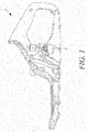
FIG. 1 illustrates a tank with a closure device for a chainsaw, according to an embodiment of the present invention; -
FIG. 2 illustrates a perspective view of the closure device with a grip portion in a retracted position, according to an embodiment of the present invention; -
FIG. 3 illustrates a perspective view of the closure device with the grip portion in a protruding position, according to an embodiment of the present invention; -
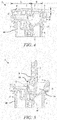
FIG. 4 illustrates a cross section view of the closure device with the grip portion in the retracted position, according to an embodiment of the present invention; -
FIG. 5 illustrates a cross section view of the closure device with the grip portion in the protruding position, according to an embodiment of the present invention; and -
FIG. 6 illustrates a cross section view of the closure device with the grip portion close to a threshold position, according to an embodiment of the present invention. - The present invention will be described more fully hereinafter with reference to the accompanying drawings, in which preferred embodiments of the invention are shown. This invention may, however, be embodied in many different forms herein; rather, these embodiments are provided so that this disclosure will be thorough and complete, and will fully convey the scope of the invention to those skilled in the art. In the drawings, like numbers refer to like references.
-
FIG. 1 illustrates a perspective view of a handle part 1, of for instance a chain saw, in accordance with an example embodiment of the present invention. Although the example embodiment is shown to be used in conjunction with the chainsaw, it should be understood that the present invention could be incorporated into any suitable type of portable handheld power tool and is not limited to use in the chainsaw only and, may be incorporated in different types of embodiments. The handle part 1, hereinafter referred to as the "handheld power tool 1", may be used in gardening or forestry applications. The handheld power tool 1 may be driven by an internal combustion engine (not shown). Further, the internal combustion engine may be either a gasoline engine or a diesel engine. In an embodiment of the present invention, a tank may be a fuel tank of the internal combustion engine. The fuel tank may include a refill opening (not shown) with threads for engagement with corresponding threads of aclosure device 2. Theclosure device 2 may be used to close the refill opening in a sealed manner with respect to the ambient by tightening theclosure device 2 into the refill opening. -
FIG. 2 illustrates a perspective view of theclosure device 2. Theclosure device 2 includes abody portion 20 provided with threads 4 for engagement with corresponding threads of the refill opening. The refill opening may be closed by tightening thebody portion 20 of theclosure device 2 into the refill opening of the fuel tank of the handheld power tool 1. Theclosure device 2 has a substantially flat top surface. Theclosure device 2 further includes askirt 5 to provide a fluid-tight seal when theclosure device 2 is fully engaged into the refill opening. - Referring to
FIG. 2 , apivotal member 6 is provided which is pivotal about apin 7 passing through a pivotal axis XX'. Thepivotal member 6 is pivotally connected to thebody portion 20 for switching between a retracted position and a protruding position. Thepivotal member 6 further includes agrip portion 3 for providing a convenient grip to an operator of the handheld power tool 1. The shape of thegrip portion 3 may be semi-circular. However, it will be apparent to a person ordinarily skilled in the art that thegrip portion 3 may have any suitable shape. - The
pivotal member 6 further includes acounter portion 8 located on an opposite side of the pivotal axis XX' with respect to thegrip portion 3. Thecounter portion 8 includes surface structure such as grooves, ribs or recesses on a surface of thepivotal member 6 which is facing away from thebody portion 20. Referring toFIG. 2 , thecounter portion 8 protrudes a distance beyond the surrounding surface of thebody portion 20 in a longitudinal direction along a longitudinal axis Y of thebody portion 20, in the retracted position of thepivotal member 6. This helps in pushing thecounter portion 8 to facilitate the opening of thegrip portion 3. Thegrip portion 3 extends a distance A (as shown inFIG. 4 ) from the pivotal axis XX' and thecounter portion 8 extends a distance B from the pivotal axis XX'. The distance B is at least a distance of 0.25 x A from the pivotal axis XX'. As an example, if the distance A is 2cm, the distance B is at least 0.5cm. In other embodiments the distance B may be at least a distance of 0.35 x A or 0.45 x A from the pivotal axis XX'. If then the distance A is 2cm, the distance B is at least 0.7cm or 0.9cm. Independent of the extending distance A of thegrip portion 3, it is preferred that the counter portion extends at least 0.5cm from the pivotal axis XX'. - A
recess 10 is formed in the periphery of thegrip portion 3 as shown in theFIG. 2 . Thegrip portion 3 may be opened by inserting a finger tip into therecess 10. Thecounter portion 8 may still be pushed down into theclosure device 2 in order to assist in moving thepivotal member 6 away from the retracted position. If the operator for instance wears gloves, he or she can push thecounter portion 8 in order to move thegrip portion 3 away from the retracted position as much to enable grip of thegrip portion 3 in therecess 10. - The
closure device 2 may further include a resilient member that holds thepivotal member 6 in the protruding position. The resilient member may be secured to thepivotal member 6 and the body portion. In various embodiments of the present invention, the resilient member may be a spring, preferably a pressure spring or a conical pressure spring. The resilient member is explained in conjunction withFIG. 6 . -
FIG. 3 illustrates a perspective view of theclosure device 2 with thegrip portion 3 in the protruding position. Theclosure device 2 includes a biasingmember 11 surrounding thepin 7 as shown in theFIG. 3 . The first end of the biasingmember 11 is secured to thegrip portion 3 and thesecond end 12 of the biasingmember 11 is secured to thebody portion 20. The biasingmember 11 urges thepivotal member 6 towards the retracted position unless thepivotal member 6 is in the protruding position. The biasingmember 11 may be a torsion spring arranged around thepin 7 for urging thepivotal member 6 to return to the retracted position. The biasingmember 11 may further be a pressure spring or a conical pressure spring. In some embodiments of the present invention, the resilient member and the biasingmember 11 may be the same member. -
FIG. 4 illustrates a cross section view of theclosure device 2 with thegrip portion 3 in the retracted position. Theclosure device 2 includes a pivotalmember fastener unit 13 and a bodyportion fastener unit 14. The pivotalmember fastener unit 13 includes one or more fastening members connected with thepivotal member 6 and the bodyportion fastener unit 14 includes one or more fastening members comiected with thebody portion 20. Specifically, the fastening members of the pivotalmember fastener unit 13 engage with the corresponding members of the bodyportion fastener unit 14 to hold thepivotal member 6 in the protruding position. In the protruding position, thegrip portion 3 of thepivotal member 6 extends outwardly of thebody portion 20 to form a grip. The operator may easily loose or tighten theclosure device 2 with the help of the grip. - Referring to
FIG. 4 , thecounter portion 8 protrudes a distance a beyond the surrounding surface of thebody portion 20 in a longitudinal direction along a longitudinal axis Y of thebody portion 20, in the retracted position of thepivotal member 6. Thereby, the pushing of thecounter portion 8 to lift thegrip portion 3 is facilitated, since thecounter portion 8 protrudes beyond thebody portion 20. Thebody portion 20 of theclosure device 2 is provided with arecess portion 15 for receiving thecounter portion 8. Specifically, thecounter portion 8 of thepivotal member 6 moves in therecess portion 15 when thepivotal member 6 moves from the retracted position towards the protruding position. - The
closure device 2 also includes a sealingring 16. The sealingring 16 may be made of an elastic rubber material and it prevents leakage of for instance fuel when the closure device is mounted in an opening on a tank of a handheld power tool. -
FIG. 5 illustrates a cross section view of theclosure device 2 with thegrip portion 3 in the protruding position. In the protruding position, the fastening members of the pivotalmember fastener unit 13 and the fastening members of the bodyportion fastener unit 14 form a snap fastening means. The fastener member of the pivotalmember fastener unit 13 may be a flexible member and the fastening member of the bodyportion fastener unit 14 may be a seat portion for holding the flexible member. The fastening member of the bodyportion fastener unit 14 may be a flexible member and the fastening member of the pivotalmember fastener unit 13 may be a seat portion for holding the flexible member. The torque required for releasing the fastening means is greater than the torque exerted by the biasingmember 11, such that thepivotal member 6 is held in the protruding position. Thereby, thepivotal member 6 must be released from the protruding position by an operator and may not be released by itself. The torque required for the fastening means to engage to a locking position is also greater than what normally may be caused by a branch or the like that may get hooked to the grip member during operation of the power tool. -
FIG. 6 shows a cross section view of theclosure device 2 with thepivotal member 6 located between the threshold position and the retracted position. The threshold position is arranged between the retracted position and the protruding position of thepivotal member 6. Aresilient member 17 can hold thepivotal member 6 in the protruding position. When thepivotal member 6 is between the threshold position and the protruding position, theresilient member 17 urges thepivotal member 6 towards the protruding position. Thus, even a small turning of thepivotal member 6 from the threshold position towards the protruding position urges thepivotal member 6 towards the protruding position. Similarly, if thepivotal member 6 is moved passed the threshold position towards the retracted position, theresilient member 17 will urge thepivotal member 6 towards the retracted position. Thereby, the function of the biasingmember 11 is incorporated in theresilient member 17. - The
resilient member 17 may be a spring, preferably a pressure spring or a conical pressure spring. A first part of thespring 17 is secured to the bottom of therecess 15 in thebody portion 20. A second part of thespring 17 is pivotally secured to a securingportion 18 of thepivotal member 6 as shown in theFIG. 6 . The securingportion 18 projects into the interior of thebody portion 20 for the retracted position of thepivotal member 6. At the connection point between thespring 17 and the securingportion 18 there is a securingaxis 19 at which thespring 17 is pivotally secured to the securingportion 18. The securingaxis 19 is parallel to thepivotal pin 7 around which thepivotal member 6 turns. When thepivotal member 6 is in a position between the threshold position and the retracted position, thespring 17 pushes the securingportion 18 and thecounter portion 8 upwards at the same side of thepivotal pin 7, to the right in the figure, such that thepivotal member 6 is pushed towards the retracted position. - When the
pivotal pin 7 around which the pivotal member turns and the securingaxis 19 is in line with a longitudinal centre of thespring 17, then thepivotal member 6 is in the threshold position. At a position of the pivotal member between the threshold position and the protruding position, the spring pushes the securingportion 18 and the securingaxis 19 upwards at one side, to the left in the figure, of thepivotal pin 7. Thecounter portion 8 is then pushed downward on the other, right, side of thepivotal pin 7 into therecess 15 in thebody portion 20. This is due to the distance between thecounter portion 8 and the securingaxis 19 provided by the securingportion 18. Thereby, thegrip portion 3 is protruding away from thebody portion 20 and is held in that position by thespring 17. The torque needed for moving thepivotal member 6 passed the threshold position towards the protruding position is set by the spring force in thespring 17. Also the position of the threshold position between the retracted position and the protruding position may be set by the arrangement of thespring 17 and the securingportion 18. - In the drawings and specification, there have been disclosed preferred embodiments and examples of the invention and, although specific terms are employed, they are used in a generic and descriptive sense only and not for the purpose of limitation, the scope of the invention being set forth in the following claims.
Claims (15)
- A closure device for closing a refill opening of a tank of a handheld power tool, the closure device comprising:a body portion configured to engage the refill opening;a pivotal member pivotally connected to the body portion and configured to pivot about a pivotal axis between a retracted position and a protruding position, wherein the pivotal member comprises a grip portion, and wherein, when the pivotal member is in the protruding position, the grip portion extends away from the body portion to form a grip for loosening or tightening the closure device relative to the refill opening; anda resilient member extending between the body portion and the pivotal member and configured to hold the pivotal member in the protruding position,wherein the pivotal member comprises a counter portion, and wherein the counter portion is located on an opposite side of the pivotal axis relative to the grip portion, andwherein the body portion comprises a recess portion, and wherein the recess portion is configured to receive the counter portion when the pivotal member is in the protruding position.
- The closure device of claim 1, wherein the counter portion is configured to be pressed into the recess portion so as to assist in moving the pivotal member away from the retracted position.
- The closure device of claim 1 or 2, wherein the pivotal member is configured to pivot from the retracted position to a threshold position and then to the protruding position, and wherein, when the pivotal member is between the threshold position and the protruding position, the resilient member urges the pivotal member towards the protruding position.
- The closure device of claim 3, wherein, when the pivotal member is between the threshold position and the retracted position, the resilient member urges the pivotal member towards the retracted position.
- The closure device of any of the preceding claims, wherein the resilient member comprises a spring, in particular wherein the spring comprises a conical pressure spring.
- The closure device of any of the preceding claims, wherein the pivotal member comprises a securing portion, wherein the resilient member is pivotally secured to the securing portion, and wherein, when the pivotal member is in the retracted position, the securing portion projects into the recess portion.
- The closure device of any of the preceding claims, wherein the pivotal member comprises a securing portion, wherein the resilient member is pivotally secured to the securing portion at a securing axis, and wherein the securing axis is substantially parallel to the pivotal axis, in particular wherein the grip portion is integral with the counter portion, and wherein the counter portion is integral with the securing portion.
- The closure device of any of the preceding claims, wherein the pivotal member comprises a surface structure that faces away from the body portion.
- The closure device of any of the preceding claims, wherein the body portion defines a longitudinal axis, and wherein the pivotal axis is substantially perpendicular to the longitudinal axis, and/or wherein the body portion comprises threads configured to engage corresponding threads on the refill opening.
- The closure device of any of the preceding claims, wherein the grip portion comprises a semi-circular shape, and/or wherein the grip portion extends a distance A from the pivotal axis, and wherein the counter portion extends at least a distance 0.25xA from the pivotal axis..
- The closure device of any of the preceding claims, wherein the pivotal member comprises a recess formed in the periphery of the grip portion, and wherein the recess is configured to receive a finger tip of an operator of the handheld power tool so as to assist in moving the pivotal member away from the retracted position.
- The closure device of any of the preceding claims, further comprising a sealing ring engaged with the body portion and made of an elastic rubber material.
- The closure device of any of the preceding claims, wherein the resilient member is pivotally secured to the pivotal member and secured within an interior of the body portion.
- The handheld power tool comprising the closure device of any of the preceding claims, wherein the handheld power tool comprises a chainsaw.
- The handheld power tool of claim 14, wherein the tank comprises a lubricant tank.
Priority Applications (1)
| Application Number | Priority Date | Filing Date | Title |
|---|---|---|---|
| EP17171723.4A EP3243681B1 (en) | 2010-02-23 | 2010-02-23 | Flip up cap |
Applications Claiming Priority (3)
| Application Number | Priority Date | Filing Date | Title |
|---|---|---|---|
| EP10846732.5A EP2539171B1 (en) | 2010-02-23 | 2010-02-23 | Flip up cap |
| EP17171723.4A EP3243681B1 (en) | 2010-02-23 | 2010-02-23 | Flip up cap |
| PCT/SE2010/050207 WO2011105937A1 (en) | 2010-02-23 | 2010-02-23 | Flip up cap |
Related Parent Applications (2)
| Application Number | Title | Priority Date | Filing Date |
|---|---|---|---|
| EP10846732.5A Division EP2539171B1 (en) | 2010-02-23 | 2010-02-23 | Flip up cap |
| EP10846732.5A Division-Into EP2539171B1 (en) | 2010-02-23 | 2010-02-23 | Flip up cap |
Publications (2)
| Publication Number | Publication Date |
|---|---|
| EP3243681A1 true EP3243681A1 (en) | 2017-11-15 |
| EP3243681B1 EP3243681B1 (en) | 2019-07-17 |
Family
ID=44507083
Family Applications (2)
| Application Number | Title | Priority Date | Filing Date |
|---|---|---|---|
| EP17171723.4A Active EP3243681B1 (en) | 2010-02-23 | 2010-02-23 | Flip up cap |
| EP10846732.5A Active EP2539171B1 (en) | 2010-02-23 | 2010-02-23 | Flip up cap |
Family Applications After (1)
| Application Number | Title | Priority Date | Filing Date |
|---|---|---|---|
| EP10846732.5A Active EP2539171B1 (en) | 2010-02-23 | 2010-02-23 | Flip up cap |
Country Status (7)
| Country | Link |
|---|---|
| US (2) | USRE47046E1 (en) |
| EP (2) | EP3243681B1 (en) |
| JP (1) | JP2013520370A (en) |
| CN (1) | CN102770299B (en) |
| BR (1) | BR112012020352B1 (en) |
| RU (1) | RU2510711C1 (en) |
| WO (1) | WO2011105937A1 (en) |
Families Citing this family (15)
| Publication number | Priority date | Publication date | Assignee | Title |
|---|---|---|---|---|
| DE102013009087A1 (en) | 2013-05-29 | 2014-12-04 | GM Global Technology Operations, LLC (n.d. Ges. d. Staates Delaware) | Locking unit, tank unit and motor vehicle |
| JP6441064B2 (en) * | 2014-12-19 | 2018-12-19 | 株式会社やまびこ | Tank cap |
| WO2016102409A1 (en) * | 2014-12-24 | 2016-06-30 | Koninklijke Philips N.V. | Drip-stop attachment for a food processing device |
| JP6473431B2 (en) * | 2016-04-01 | 2019-02-20 | 株式会社ニトリホールディングス | Storage case and hinge structure |
| JP6929748B2 (en) * | 2017-09-29 | 2021-09-01 | 株式会社マキタ | Tank cap |
| GB201717486D0 (en) | 2017-10-24 | 2017-12-06 | Nicoventures Holdings Ltd | Mechanism for hatch of electronic aerosol provision device |
| GB201717484D0 (en) * | 2017-10-24 | 2017-12-06 | Nicoventures Holdings Ltd | Electronic aerosol provision device |
| GB201717489D0 (en) | 2017-10-24 | 2017-12-06 | Nicoventures Holdings Ltd | Electronic aerosol provision device |
| GB201717480D0 (en) | 2017-10-24 | 2017-12-06 | Nicoventures Holdings Ltd | Electronic aerosol provision device with seal |
| GB201717479D0 (en) | 2017-10-24 | 2017-12-06 | Nicoventures Holdings Ltd | Hatch section for an electronic aerosol provision device |
| RU2739630C2 (en) * | 2019-02-12 | 2020-12-28 | Федеральное государственное бюджетное образовательное учреждение высшего образования Балтийский государственный технический университет "ВОЕНМЕХ" им. Д.Ф. Устинова (БГТУ "ВОЕНМЕХ") | Closing mechanism |
| WO2020236046A1 (en) * | 2019-05-20 | 2020-11-26 | Husqvarna Ab | Power tool tank assembly,closure device, and power tool |
| US11052755B2 (en) * | 2019-07-11 | 2021-07-06 | Martinrea International US Inc. | Compound spring for capless fuel door |
| DE202019104547U1 (en) * | 2019-08-19 | 2020-11-26 | Rpc Formatec Gmbh | Donor |
| CN114056440B (en) * | 2021-12-01 | 2025-06-03 | 长春捷翼汽车科技股份有限公司 | A dustproof device with self-locking and rebound functions and a charging device |
Citations (3)
| Publication number | Priority date | Publication date | Assignee | Title |
|---|---|---|---|---|
| DE697929C (en) * | 1938-09-11 | 1940-10-28 | E H Dr Phil H C Ernst Heinkel | Container screw connection, especially for aircraft |
| GB1264263A (en) * | 1969-02-25 | 1972-02-16 | ||
| US20070090113A1 (en) * | 2005-10-21 | 2007-04-26 | Nissan Technical Center North America, Inc. | Fuel cap for vehicle |
Family Cites Families (37)
| Publication number | Priority date | Publication date | Assignee | Title |
|---|---|---|---|---|
| US1689979A (en) * | 1928-02-14 | 1928-10-30 | Homer E Tate | Gas-tank cap |
| US1818608A (en) * | 1929-05-08 | 1931-08-11 | George C Chafkin | Safety gas tank cap |
| US3820680A (en) * | 1972-11-20 | 1974-06-28 | Stant Mfg Co | Torque-limiting device |
| DE7616881U1 (en) | 1976-05-26 | 1976-09-16 | Bayerische Motoren Werke Ag, 8000 Muenchen | FUEL TANK FOR SINGLE TRACK VEHICLES, IN PARTICULAR MOTORCYCLES |
| US4124151A (en) | 1976-11-22 | 1978-11-07 | Polytop Corporation | Toggle type dispensing closure |
| US4091959A (en) * | 1977-02-03 | 1978-05-30 | Banion John D O | Gas cap |
| JPS55131823U (en) | 1979-03-13 | 1980-09-18 | ||
| JPS591890Y2 (en) | 1981-04-23 | 1984-01-19 | バイエリツシエ モ−ト−レン ウエルケ アクチエンゲゼルシヤフト | Fuel tanks for single-track vehicles, especially motorcycles |
| US4402435A (en) | 1981-05-15 | 1983-09-06 | Libit Sidney M | Dispensing type cap closure |
| US4399928A (en) | 1982-04-14 | 1983-08-23 | Janler Corporation | Closure cap |
| JPS596524U (en) | 1982-07-06 | 1984-01-17 | 三菱自動車工業株式会社 | Cover structure of vehicle fuel filler port |
| JPS6041339U (en) | 1983-08-30 | 1985-03-23 | 株式会社 共立 | Tank cap for power working machines |
| DE3336149A1 (en) | 1983-10-05 | 1985-04-18 | Fa. Andreas Stihl, 7050 Waiblingen | SCREW CAP FOR FUEL TANK |
| DE8405440U1 (en) | 1984-02-22 | 1984-04-12 | Walter Alfmeier GmbH + Co Präzisions-Baugruppenelemente, 8830 Treuchtlingen | Closure device of a container |
| US5339487A (en) * | 1990-01-19 | 1994-08-23 | Rexair, Inc. | Filtering means for a liquid pan assembly for a liquid bath vacuum cleaner |
| DE4436543C2 (en) * | 1993-11-12 | 2002-07-11 | Stihl Maschf Andreas | Tensioning device for a chain saw of a motor chain saw running over a saw blade |
| US5480055A (en) * | 1994-05-06 | 1996-01-02 | Stant Manufacturing Inc. | Quick-on cap with removal delay mechanism |
| FR2743786B1 (en) | 1996-01-23 | 1999-04-16 | Stihl Maschf Andreas | PLUG FOR A FILLING OPENING OF A FUEL TANK |
| US6237797B1 (en) | 1999-10-29 | 2001-05-29 | John J. Hurford | Fuel cap extension |
| US6560879B2 (en) * | 2001-08-02 | 2003-05-13 | Wci Outdoor Products, Inc. | Chain saw adjuster |
| EP1314605B1 (en) * | 2001-11-26 | 2005-01-26 | Toyoda Gosei Co., Ltd. | Cap device |
| JP2003341706A (en) | 2002-05-20 | 2003-12-03 | Kioritz Corp | Tank cap |
| JP4349785B2 (en) | 2002-10-11 | 2009-10-21 | 日本クラウンコルク株式会社 | Synthetic resin container lid with tamper evident characteristics |
| RU2329081C2 (en) * | 2002-12-20 | 2008-07-20 | ЭсДжиДжи ПЕЙТЕНТС ЭлЭлСи | Sport ball with self-contained inflation mechanism having pressure relief and indication capability |
| US7467736B2 (en) | 2003-09-22 | 2008-12-23 | L'oreal | Closure and dispensing device |
| US6877233B1 (en) * | 2004-01-08 | 2005-04-12 | Electrolux Home Products, Inc. | Chain saw adjuster mechanism with locking teeth |
| EP1607294A1 (en) | 2004-06-18 | 2005-12-21 | Ford Global Technologies, LLC | Filler cap for under bonnet applications |
| US6968874B1 (en) * | 2004-10-07 | 2005-11-29 | Martinrea Industries, Inc. | Capless automotive fueling system |
| US7107689B2 (en) * | 2004-10-08 | 2006-09-19 | Husqvarna Outdoor Products Inc. | Bar knob with integrated lock |
| USD537024S1 (en) * | 2005-06-17 | 2007-02-20 | Kawasaki Jukogyo Kabushiki Kaisha | Fuel tank cap for a vehicle |
| DE102005047882B4 (en) | 2005-10-06 | 2017-04-27 | Andreas Stihl Ag & Co. Kg | Hand-held implement |
| RU2312775C1 (en) * | 2006-03-16 | 2007-12-20 | Общество с ограниченной ответственностью "Нижегородское производственное объединение "Волга" Всероссийского общества слепых" | Filler neck plug of automobile fuel tank (two versions) |
| US7739800B2 (en) | 2006-10-24 | 2010-06-22 | Hurley Edward P | Combination blower, trimmer and edger for tending vegetation |
| WO2008108690A1 (en) * | 2007-03-02 | 2008-09-12 | Husqvarna Aktiebolag | Filler cap |
| CN102089217B (en) | 2007-06-19 | 2013-06-12 | 邓肯·纽曼 | Adjustable closure for a container |
| GB2450720A (en) | 2007-07-04 | 2009-01-07 | Black & Decker Inc | Power cutter with pleated filter |
| RU2363597C1 (en) * | 2007-10-31 | 2009-08-10 | Институт физики им. Л.В. Киренского Сибирского отделения РАН | Vehicle fuel tank filler cover |
-
2010
- 2010-02-23 EP EP17171723.4A patent/EP3243681B1/en active Active
- 2010-02-23 US US15/457,090 patent/USRE47046E1/en active Active
- 2010-02-23 CN CN201080064584.9A patent/CN102770299B/en active Active
- 2010-02-23 RU RU2012140507/02A patent/RU2510711C1/en active
- 2010-02-23 EP EP10846732.5A patent/EP2539171B1/en active Active
- 2010-02-23 WO PCT/SE2010/050207 patent/WO2011105937A1/en not_active Ceased
- 2010-02-23 BR BR112012020352-5A patent/BR112012020352B1/en active IP Right Grant
- 2010-02-23 US US13/580,504 patent/US9260008B2/en not_active Ceased
- 2010-02-23 JP JP2012553839A patent/JP2013520370A/en active Pending
Patent Citations (3)
| Publication number | Priority date | Publication date | Assignee | Title |
|---|---|---|---|---|
| DE697929C (en) * | 1938-09-11 | 1940-10-28 | E H Dr Phil H C Ernst Heinkel | Container screw connection, especially for aircraft |
| GB1264263A (en) * | 1969-02-25 | 1972-02-16 | ||
| US20070090113A1 (en) * | 2005-10-21 | 2007-04-26 | Nissan Technical Center North America, Inc. | Fuel cap for vehicle |
Also Published As
| Publication number | Publication date |
|---|---|
| JP2013520370A (en) | 2013-06-06 |
| US20120318797A1 (en) | 2012-12-20 |
| CN102770299A (en) | 2012-11-07 |
| RU2012140507A (en) | 2014-03-27 |
| WO2011105937A1 (en) | 2011-09-01 |
| CN102770299B (en) | 2016-08-03 |
| BR112012020352A2 (en) | 2016-05-03 |
| EP2539171A4 (en) | 2017-11-08 |
| EP2539171A1 (en) | 2013-01-02 |
| US9260008B2 (en) | 2016-02-16 |
| EP2539171B1 (en) | 2019-07-10 |
| EP3243681B1 (en) | 2019-07-17 |
| USRE47046E1 (en) | 2018-09-18 |
| RU2510711C1 (en) | 2014-04-10 |
| BR112012020352B1 (en) | 2020-12-15 |
Similar Documents
| Publication | Publication Date | Title |
|---|---|---|
| EP3243681B1 (en) | Flip up cap | |
| US6834769B2 (en) | Hinge cap | |
| KR101714178B1 (en) | Locking mechanism of the tubular body | |
| CN201566932U (en) | Cover for fluid container | |
| US9958098B2 (en) | Tubular-member lock mechanism | |
| EP2645900B1 (en) | Clip for attaching articles together | |
| US20080256805A1 (en) | Handle latching mechanism | |
| US6478346B1 (en) | Snap closure | |
| US6109467A (en) | Closure cap for an operating fluid container | |
| US8839973B2 (en) | Fuel inlet device with a cap member for a fuel tank | |
| JP2008528367A (en) | Filling port cover | |
| US10759570B2 (en) | Tank cap | |
| US6003735A (en) | Hand-portable safety-canister w/vari-flow thumb-valve | |
| JP3209567U (en) | Sealing device | |
| US20220154836A1 (en) | Fuel cap with duckbill valve | |
| JP2015226980A (en) | Flip-up cap | |
| CN221930769U (en) | Garden tool | |
| US20110240590A1 (en) | Closure arrangement | |
| US20070000727A1 (en) | Drain valve assembly | |
| KR101832691B1 (en) | oilhole settlement structure | |
| GB2176578A (en) | Valve protector | |
| RU2615571C1 (en) | Cover for tool working device |
Legal Events
| Date | Code | Title | Description |
|---|---|---|---|
| PUAI | Public reference made under article 153(3) epc to a published international application that has entered the european phase |
Free format text: ORIGINAL CODE: 0009012 |
|
| STAA | Information on the status of an ep patent application or granted ep patent |
Free format text: STATUS: REQUEST FOR EXAMINATION WAS MADE |
|
| 17P | Request for examination filed |
Effective date: 20170518 |
|
| AC | Divisional application: reference to earlier application |
Ref document number: 2539171 Country of ref document: EP Kind code of ref document: P |
|
| AK | Designated contracting states |
Kind code of ref document: A1 Designated state(s): AT BE BG CH CY CZ DE DK EE ES FI FR GB GR HR HU IE IS IT LI LT LU LV MC MK MT NL NO PL PT RO SE SI SK SM TR |
|
| RIC1 | Information provided on ipc code assigned before grant |
Ipc: B60K 15/05 20060101AFI20181213BHEP |
|
| GRAP | Despatch of communication of intention to grant a patent |
Free format text: ORIGINAL CODE: EPIDOSNIGR1 |
|
| STAA | Information on the status of an ep patent application or granted ep patent |
Free format text: STATUS: GRANT OF PATENT IS INTENDED |
|
| INTG | Intention to grant announced |
Effective date: 20190214 |
|
| GRAA | (expected) grant |
Free format text: ORIGINAL CODE: 0009210 |
|
| STAA | Information on the status of an ep patent application or granted ep patent |
Free format text: STATUS: THE PATENT HAS BEEN GRANTED |
|
| AC | Divisional application: reference to earlier application |
Ref document number: 2539171 Country of ref document: EP Kind code of ref document: P |
|
| AK | Designated contracting states |
Kind code of ref document: B1 Designated state(s): AT BE BG CH CY CZ DE DK EE ES FI FR GB GR HR HU IE IS IT LI LT LU LV MC MK MT NL NO PL PT RO SE SI SK SM TR |
|
| REG | Reference to a national code |
Ref country code: GB Ref legal event code: FG4D |
|
| REG | Reference to a national code |
Ref country code: CH Ref legal event code: EP |
|
| REG | Reference to a national code |
Ref country code: IE Ref legal event code: FG4D |
|
| REG | Reference to a national code |
Ref country code: DE Ref legal event code: R096 Ref document number: 602010060095 Country of ref document: DE |
|
| REG | Reference to a national code |
Ref country code: AT Ref legal event code: REF Ref document number: 1155525 Country of ref document: AT Kind code of ref document: T Effective date: 20190815 |
|
| REG | Reference to a national code |
Ref country code: SE Ref legal event code: TRGR |
|
| REG | Reference to a national code |
Ref country code: NL Ref legal event code: FP |
|
| REG | Reference to a national code |
Ref country code: LT Ref legal event code: MG4D |
|
| PG25 | Lapsed in a contracting state [announced via postgrant information from national office to epo] |
Ref country code: NO Free format text: LAPSE BECAUSE OF FAILURE TO SUBMIT A TRANSLATION OF THE DESCRIPTION OR TO PAY THE FEE WITHIN THE PRESCRIBED TIME-LIMIT Effective date: 20191017 Ref country code: FI Free format text: LAPSE BECAUSE OF FAILURE TO SUBMIT A TRANSLATION OF THE DESCRIPTION OR TO PAY THE FEE WITHIN THE PRESCRIBED TIME-LIMIT Effective date: 20190717 Ref country code: HR Free format text: LAPSE BECAUSE OF FAILURE TO SUBMIT A TRANSLATION OF THE DESCRIPTION OR TO PAY THE FEE WITHIN THE PRESCRIBED TIME-LIMIT Effective date: 20190717 Ref country code: BG Free format text: LAPSE BECAUSE OF FAILURE TO SUBMIT A TRANSLATION OF THE DESCRIPTION OR TO PAY THE FEE WITHIN THE PRESCRIBED TIME-LIMIT Effective date: 20191017 Ref country code: PT Free format text: LAPSE BECAUSE OF FAILURE TO SUBMIT A TRANSLATION OF THE DESCRIPTION OR TO PAY THE FEE WITHIN THE PRESCRIBED TIME-LIMIT Effective date: 20191118 Ref country code: LT Free format text: LAPSE BECAUSE OF FAILURE TO SUBMIT A TRANSLATION OF THE DESCRIPTION OR TO PAY THE FEE WITHIN THE PRESCRIBED TIME-LIMIT Effective date: 20190717 |
|
| PG25 | Lapsed in a contracting state [announced via postgrant information from national office to epo] |
Ref country code: ES Free format text: LAPSE BECAUSE OF FAILURE TO SUBMIT A TRANSLATION OF THE DESCRIPTION OR TO PAY THE FEE WITHIN THE PRESCRIBED TIME-LIMIT Effective date: 20190717 Ref country code: GR Free format text: LAPSE BECAUSE OF FAILURE TO SUBMIT A TRANSLATION OF THE DESCRIPTION OR TO PAY THE FEE WITHIN THE PRESCRIBED TIME-LIMIT Effective date: 20191018 Ref country code: LV Free format text: LAPSE BECAUSE OF FAILURE TO SUBMIT A TRANSLATION OF THE DESCRIPTION OR TO PAY THE FEE WITHIN THE PRESCRIBED TIME-LIMIT Effective date: 20190717 Ref country code: IS Free format text: LAPSE BECAUSE OF FAILURE TO SUBMIT A TRANSLATION OF THE DESCRIPTION OR TO PAY THE FEE WITHIN THE PRESCRIBED TIME-LIMIT Effective date: 20191117 |
|
| PG25 | Lapsed in a contracting state [announced via postgrant information from national office to epo] |
Ref country code: TR Free format text: LAPSE BECAUSE OF FAILURE TO SUBMIT A TRANSLATION OF THE DESCRIPTION OR TO PAY THE FEE WITHIN THE PRESCRIBED TIME-LIMIT Effective date: 20190717 |
|
| PG25 | Lapsed in a contracting state [announced via postgrant information from national office to epo] |
Ref country code: RO Free format text: LAPSE BECAUSE OF FAILURE TO SUBMIT A TRANSLATION OF THE DESCRIPTION OR TO PAY THE FEE WITHIN THE PRESCRIBED TIME-LIMIT Effective date: 20190717 Ref country code: PL Free format text: LAPSE BECAUSE OF FAILURE TO SUBMIT A TRANSLATION OF THE DESCRIPTION OR TO PAY THE FEE WITHIN THE PRESCRIBED TIME-LIMIT Effective date: 20190717 Ref country code: DK Free format text: LAPSE BECAUSE OF FAILURE TO SUBMIT A TRANSLATION OF THE DESCRIPTION OR TO PAY THE FEE WITHIN THE PRESCRIBED TIME-LIMIT Effective date: 20190717 Ref country code: IT Free format text: LAPSE BECAUSE OF FAILURE TO SUBMIT A TRANSLATION OF THE DESCRIPTION OR TO PAY THE FEE WITHIN THE PRESCRIBED TIME-LIMIT Effective date: 20190717 Ref country code: EE Free format text: LAPSE BECAUSE OF FAILURE TO SUBMIT A TRANSLATION OF THE DESCRIPTION OR TO PAY THE FEE WITHIN THE PRESCRIBED TIME-LIMIT Effective date: 20190717 |
|
| PG25 | Lapsed in a contracting state [announced via postgrant information from national office to epo] |
Ref country code: CZ Free format text: LAPSE BECAUSE OF FAILURE TO SUBMIT A TRANSLATION OF THE DESCRIPTION OR TO PAY THE FEE WITHIN THE PRESCRIBED TIME-LIMIT Effective date: 20190717 Ref country code: SM Free format text: LAPSE BECAUSE OF FAILURE TO SUBMIT A TRANSLATION OF THE DESCRIPTION OR TO PAY THE FEE WITHIN THE PRESCRIBED TIME-LIMIT Effective date: 20190717 Ref country code: IS Free format text: LAPSE BECAUSE OF FAILURE TO SUBMIT A TRANSLATION OF THE DESCRIPTION OR TO PAY THE FEE WITHIN THE PRESCRIBED TIME-LIMIT Effective date: 20200224 Ref country code: SK Free format text: LAPSE BECAUSE OF FAILURE TO SUBMIT A TRANSLATION OF THE DESCRIPTION OR TO PAY THE FEE WITHIN THE PRESCRIBED TIME-LIMIT Effective date: 20190717 |
|
| REG | Reference to a national code |
Ref country code: DE Ref legal event code: R097 Ref document number: 602010060095 Country of ref document: DE |
|
| REG | Reference to a national code |
Ref country code: AT Ref legal event code: UEP Ref document number: 1155525 Country of ref document: AT Kind code of ref document: T Effective date: 20190717 |
|
| PLBE | No opposition filed within time limit |
Free format text: ORIGINAL CODE: 0009261 |
|
| STAA | Information on the status of an ep patent application or granted ep patent |
Free format text: STATUS: NO OPPOSITION FILED WITHIN TIME LIMIT |
|
| PG2D | Information on lapse in contracting state deleted |
Ref country code: IS |
|
| 26N | No opposition filed |
Effective date: 20200603 |
|
| PG25 | Lapsed in a contracting state [announced via postgrant information from national office to epo] |
Ref country code: SI Free format text: LAPSE BECAUSE OF FAILURE TO SUBMIT A TRANSLATION OF THE DESCRIPTION OR TO PAY THE FEE WITHIN THE PRESCRIBED TIME-LIMIT Effective date: 20190717 |
|
| REG | Reference to a national code |
Ref country code: CH Ref legal event code: PL |
|
| GBPC | Gb: european patent ceased through non-payment of renewal fee |
Effective date: 20200223 |
|
| PG25 | Lapsed in a contracting state [announced via postgrant information from national office to epo] |
Ref country code: MC Free format text: LAPSE BECAUSE OF FAILURE TO SUBMIT A TRANSLATION OF THE DESCRIPTION OR TO PAY THE FEE WITHIN THE PRESCRIBED TIME-LIMIT Effective date: 20190717 Ref country code: LU Free format text: LAPSE BECAUSE OF NON-PAYMENT OF DUE FEES Effective date: 20200223 |
|
| PG25 | Lapsed in a contracting state [announced via postgrant information from national office to epo] |
Ref country code: LI Free format text: LAPSE BECAUSE OF NON-PAYMENT OF DUE FEES Effective date: 20200229 Ref country code: CH Free format text: LAPSE BECAUSE OF NON-PAYMENT OF DUE FEES Effective date: 20200229 |
|
| PG25 | Lapsed in a contracting state [announced via postgrant information from national office to epo] |
Ref country code: GB Free format text: LAPSE BECAUSE OF NON-PAYMENT OF DUE FEES Effective date: 20200223 Ref country code: IE Free format text: LAPSE BECAUSE OF NON-PAYMENT OF DUE FEES Effective date: 20200223 |
|
| PGFP | Annual fee paid to national office [announced via postgrant information from national office to epo] |
Ref country code: AT Payment date: 20220112 Year of fee payment: 13 |
|
| PG25 | Lapsed in a contracting state [announced via postgrant information from national office to epo] |
Ref country code: MT Free format text: LAPSE BECAUSE OF FAILURE TO SUBMIT A TRANSLATION OF THE DESCRIPTION OR TO PAY THE FEE WITHIN THE PRESCRIBED TIME-LIMIT Effective date: 20190717 Ref country code: CY Free format text: LAPSE BECAUSE OF FAILURE TO SUBMIT A TRANSLATION OF THE DESCRIPTION OR TO PAY THE FEE WITHIN THE PRESCRIBED TIME-LIMIT Effective date: 20190717 |
|
| PGFP | Annual fee paid to national office [announced via postgrant information from national office to epo] |
Ref country code: SE Payment date: 20220112 Year of fee payment: 13 Ref country code: NL Payment date: 20220112 Year of fee payment: 13 Ref country code: FR Payment date: 20220107 Year of fee payment: 13 Ref country code: BE Payment date: 20220107 Year of fee payment: 13 |
|
| PG25 | Lapsed in a contracting state [announced via postgrant information from national office to epo] |
Ref country code: MK Free format text: LAPSE BECAUSE OF FAILURE TO SUBMIT A TRANSLATION OF THE DESCRIPTION OR TO PAY THE FEE WITHIN THE PRESCRIBED TIME-LIMIT Effective date: 20190717 |
|
| P01 | Opt-out of the competence of the unified patent court (upc) registered |
Effective date: 20230419 |
|
| REG | Reference to a national code |
Ref country code: SE Ref legal event code: EUG |
|
| REG | Reference to a national code |
Ref country code: NL Ref legal event code: MM Effective date: 20230301 |
|
| REG | Reference to a national code |
Ref country code: AT Ref legal event code: MM01 Ref document number: 1155525 Country of ref document: AT Kind code of ref document: T Effective date: 20230223 |
|
| REG | Reference to a national code |
Ref country code: BE Ref legal event code: MM Effective date: 20230228 |
|
| PG25 | Lapsed in a contracting state [announced via postgrant information from national office to epo] |
Ref country code: SE Free format text: LAPSE BECAUSE OF NON-PAYMENT OF DUE FEES Effective date: 20230224 Ref country code: AT Free format text: LAPSE BECAUSE OF NON-PAYMENT OF DUE FEES Effective date: 20230223 |
|
| PG25 | Lapsed in a contracting state [announced via postgrant information from national office to epo] |
Ref country code: NL Free format text: LAPSE BECAUSE OF NON-PAYMENT OF DUE FEES Effective date: 20230301 |
|
| PG25 | Lapsed in a contracting state [announced via postgrant information from national office to epo] |
Ref country code: FR Free format text: LAPSE BECAUSE OF NON-PAYMENT OF DUE FEES Effective date: 20230228 |
|
| PG25 | Lapsed in a contracting state [announced via postgrant information from national office to epo] |
Ref country code: BE Free format text: LAPSE BECAUSE OF NON-PAYMENT OF DUE FEES Effective date: 20230228 |
|
| PGFP | Annual fee paid to national office [announced via postgrant information from national office to epo] |
Ref country code: DE Payment date: 20260109 Year of fee payment: 17 |