EP3243578A2 - Method and press tool for producing a complex sheet metal part with high draw depth - Google Patents
Method and press tool for producing a complex sheet metal part with high draw depth Download PDFInfo
- Publication number
- EP3243578A2 EP3243578A2 EP17000777.7A EP17000777A EP3243578A2 EP 3243578 A2 EP3243578 A2 EP 3243578A2 EP 17000777 A EP17000777 A EP 17000777A EP 3243578 A2 EP3243578 A2 EP 3243578A2
- Authority
- EP
- European Patent Office
- Prior art keywords
- punch
- sheet
- die
- tool
- hold
- Prior art date
- Legal status (The legal status is an assumption and is not a legal conclusion. Google has not performed a legal analysis and makes no representation as to the accuracy of the status listed.)
- Granted
Links
Images
Classifications
-
- B—PERFORMING OPERATIONS; TRANSPORTING
- B21—MECHANICAL METAL-WORKING WITHOUT ESSENTIALLY REMOVING MATERIAL; PUNCHING METAL
- B21D—WORKING OR PROCESSING OF SHEET METAL OR METAL TUBES, RODS OR PROFILES WITHOUT ESSENTIALLY REMOVING MATERIAL; PUNCHING METAL
- B21D22/00—Shaping without cutting, by stamping, spinning, or deep-drawing
- B21D22/02—Stamping using rigid devices or tools
- B21D22/06—Stamping using rigid devices or tools having relatively-movable die parts
-
- B—PERFORMING OPERATIONS; TRANSPORTING
- B21—MECHANICAL METAL-WORKING WITHOUT ESSENTIALLY REMOVING MATERIAL; PUNCHING METAL
- B21D—WORKING OR PROCESSING OF SHEET METAL OR METAL TUBES, RODS OR PROFILES WITHOUT ESSENTIALLY REMOVING MATERIAL; PUNCHING METAL
- B21D22/00—Shaping without cutting, by stamping, spinning, or deep-drawing
- B21D22/20—Deep-drawing
- B21D22/26—Deep-drawing for making peculiarly, e.g. irregularly, shaped articles
-
- B—PERFORMING OPERATIONS; TRANSPORTING
- B21—MECHANICAL METAL-WORKING WITHOUT ESSENTIALLY REMOVING MATERIAL; PUNCHING METAL
- B21D—WORKING OR PROCESSING OF SHEET METAL OR METAL TUBES, RODS OR PROFILES WITHOUT ESSENTIALLY REMOVING MATERIAL; PUNCHING METAL
- B21D22/00—Shaping without cutting, by stamping, spinning, or deep-drawing
- B21D22/20—Deep-drawing
- B21D22/22—Deep-drawing with devices for holding the edge of the blanks
-
- B—PERFORMING OPERATIONS; TRANSPORTING
- B21—MECHANICAL METAL-WORKING WITHOUT ESSENTIALLY REMOVING MATERIAL; PUNCHING METAL
- B21D—WORKING OR PROCESSING OF SHEET METAL OR METAL TUBES, RODS OR PROFILES WITHOUT ESSENTIALLY REMOVING MATERIAL; PUNCHING METAL
- B21D24/00—Special deep-drawing arrangements in, or in connection with, presses
- B21D24/04—Blank holders; Mounting means therefor
-
- B—PERFORMING OPERATIONS; TRANSPORTING
- B21—MECHANICAL METAL-WORKING WITHOUT ESSENTIALLY REMOVING MATERIAL; PUNCHING METAL
- B21D—WORKING OR PROCESSING OF SHEET METAL OR METAL TUBES, RODS OR PROFILES WITHOUT ESSENTIALLY REMOVING MATERIAL; PUNCHING METAL
- B21D24/00—Special deep-drawing arrangements in, or in connection with, presses
- B21D24/10—Devices controlling or operating blank holders independently, or in conjunction with dies
-
- B—PERFORMING OPERATIONS; TRANSPORTING
- B21—MECHANICAL METAL-WORKING WITHOUT ESSENTIALLY REMOVING MATERIAL; PUNCHING METAL
- B21D—WORKING OR PROCESSING OF SHEET METAL OR METAL TUBES, RODS OR PROFILES WITHOUT ESSENTIALLY REMOVING MATERIAL; PUNCHING METAL
- B21D37/00—Tools as parts of machines covered by this subclass
- B21D37/10—Die sets; Pillar guides
Abstract
Verfahren zur Herstellung eines komplexen Blechformteils mittels pressengebundenem Werkzeug, mit: - Einlegen eines Blechs (M) und Abwärtshub des Werkzeugoberteils (120), wobei das Blech (M) im Randbereich zwischen Matrizenring (160) und Niederhalter (140) geklemmt wird; - weiterer Abwärtshub, wobei das Blech (M) zuerst über ausgefahrene Stempeleinsätze (131, 132, 133) gezogen wird und dabei lokale Materialbevorratungen im Blech (M) erzeugt werden; - weiterer Abwärtshub bis Matrizenring (160) und Niederhalter (140) ihre Totpunkte erreichen, wobei gleichzeitig die Stempeleinsätze (131, 132, 133) aktiv zurückbewegt werden und die lokalen Materialbevorratungen freigeben und wobei das Blech (M) bereits bereichsweise zwischen Matrizenring (160) und Stempel (130) ausgeformt wird; - weiterer Abwärtshub bis die Matrize (150) ihren Totpunkt erreicht, wobei das Nachfließen aus dem Randbereich verhindert und das Blech (M) lediglich unter Ausnutzung der lokalen Materialbevorratungen zwischen Matrize (150) und Stempel (130) fertig ausgeformt wird. Ferner zur Ausführung dieses Verfahrens geeignetes Werkzeug (100).Method for producing a complex sheet metal part by means of a press-bonded tool, comprising: - Inserting a sheet (M) and downward stroke of the upper tool part (120), wherein the sheet (M) in the edge region between the die ring (160) and hold-down (140) is clamped; - Further downstroke, wherein the sheet (M) is first pulled over extended punch inserts (131, 132, 133) and thereby local material supplies in the sheet (M) are generated; - Further down stroke to Matrizenring (160) and hold down (140) reach their dead points, while the punch inserts (131, 132, 133) are actively moved back and release the local material stocks and wherein the sheet (M) already partially between Matrizenring (160) and stamp (130) is formed; - Further downward stroke until the die (150) reaches its dead center, wherein the Nachfließen prevented from the edge region and the sheet (M) only by using the local material stocks between die (150) and punch (130) is fully formed. Furthermore, tool (100) suitable for carrying out this method.
Description
Die Erfindung betrifft ein Verfahren zur Herstellung eines komplexen Blechformteils durch Umformen eines Blechs mittels pressengebundenem Werkzeug (Pressenwerkzeug) und ein hierfür geeignetes Pressenwerkzeug.The invention relates to a method for producing a complex sheet metal part by forming a sheet metal by means of press-bound tool (press tool) and a press tool suitable for this purpose.
Komplexe Blechformteile, insbesondere für die Anwendung im Karosseriebau, unterscheiden sich zu einfachen Blechformteilen (wie bspw. einem Napf oder einer Wanne) durch eine aufwändigere Formgestaltung, die typischerweise unterschiedliche Flächenbereiche und insbesondere auch weitere Gestaltungsmerkmale, bspw. Design- bzw. Stylingkanten und/oder Versteifungskanten mit kleinen Radien, umfasst. Da der umformtechnischen Machbarkeit Grenzen gesetzt sind, ist die Herstellung solcher komplexen Blechformteile mitunter äußerst schwierig und aufwändig. Besondere Probleme bestehen dann, wenn unter Serienfertigungsbedingungen hohe Ziehtiefen realisiert werden sollen.Complex sheet metal parts, in particular for use in body construction, differ from simple sheet metal parts (such as a cup or a tub) by a more complex design, typically different surface areas and especially other design features, for example. Design or styling edges and / or Stiffening edges with small radii, includes. Since the forming technology feasibility limits, the production of such complex sheet metal parts is sometimes extremely difficult and expensive. Particular problems exist when high draw depths are to be realized under series production conditions.
Zur Realisierung hoher Ziehtiefen sind in der
Ausgehend von diesem Stand der Technik liegt der Erfindung die Aufgabe zugrunde, ein verbessertes Verfahren und ein verbessertes Werkzeug zur Herstellung eines komplexen und insbesondere auch großflächigen (bspw. > 0,5 m^2) Blechformteils anzugeben, mit denen unter Serienfertigungsbedingungen bei einwandfreier Teilequalität eine hohe Ziehtiefe erreichbar ist.Based on this prior art, the present invention seeks to provide an improved method and an improved tool for producing a complex and in particular large-area (eg.> 0.5 m ^ 2) sheet metal part, with which Series production conditions with perfect part quality a high draw depth is achievable.
Diese Aufgabe wird gelöst mit einem erfindungsgemäßen Verfahren entsprechend dem Patentanspruch 1 und durch ein erfindungsgemäßes Pressenwerkzeug entsprechend dem nebengeordneten Patentanspruch. Bevorzugte Weiterbildungen und Ausgestaltungen der Erfindung ergeben sich analog für beide Erfindungsgegenstände aus den abhängigen Patentansprüchen, der nachfolgenden Beschreibung und der Zeichnung.This object is achieved with a method according to the invention according to the patent claim 1 and by an inventive press tool according to the independent claim. Preferred developments and refinements of the invention are analogous to both subject matters of the dependent claims, the following description and the drawings.
Das erfindungsgemäße Verfahren zur Herstellung eines komplexen Blechformteils mittels pressengebundenem Werkzeug (Pressenwerkzeug), dessen Werkzeugunterteil einen Stempel, einen den Stempel umgebenden (verdrängbaren) Nieder- bzw. Blechhalter und mehrere bewegbare Stempeleinsätze (mit Umform- bzw. Formgebungsfunktion) aufweist und dessen Werkzeugoberteil eine Matrize und einen die Matrize umgebenden Matrizenring aufweist, hat folgenden Ablauf:
- Einlegen eines Blechs, insbesondere in Gestalt einer Blechplatine, in das offene Werkzeug und Schließen des Werkzeugs durch Abwärtshub des Werkzeugoberteils, wobei das Blech in seinem Randbereich zwischen dem Matrizenring und dem Niederhalter geklemmt bzw. eingeklemmt wird;
- weiterer Abwärtshub bei dem der Matrizenring den Niederhalter nach unten verdrängt, wobei das Blech zuerst über die ausgefahrenen und über die Stempeloberfläche vorstehenden Stempeleinsätze gezogen wird und dabei im Blech lokale Materialbevorratungen erzeugt werden;
- weiterer Abwärtshub bis der Matrizenring und der Niederhalter ihre unteren Totpunkte erreichen, wobei gleichzeitig die Stempeleinsätze aktiv zurückbewegt werden und dadurch die zuvor erzeugten lokalen Materialbevorratungen freigeben und wobei das Blech bereits bereichsweise zwischen Matrizenring und Stempel ausgeformt wird;
- weiterer Abwärtshub, bis auch die Matrize schließlich ihren unteren Totpunkt erreicht, wobei durch eine doppelte randseitige Klemmung des Blechs zwischen dem Matrizenring und dem Niederhalter sowie zwischen dem Matrizenring und dem Stempel das Nachfließen von Blechmaterial aus dem Randbereich verhindert wird und das Blech lediglich unter Ausnutzung der zuvor erzeugten lokalen Materialbevorratungen zwischen der Matrize und dem Stempel fertig ausgeformt wird;
- gegebenenfalls Öffnen des Werkzeugs (durch Aufwärtshub des Werkzeugoberteils) und Entnehmen des Blechformteils.
- Inserting a sheet, in particular in the form of a sheet metal blank, in the open tool and closing the tool by downward stroke of the tool shell, wherein the sheet is clamped or clamped in its edge region between the die ring and the hold-down;
- another downward stroke in which the Matrizenring displaces the hold-down, the sheet is first pulled over the extended and over the stamp surface protruding punch inserts and are generated in the sheet local material stocks;
- further downward stroke until the die ring and the blank holder reach their bottom dead centers, at the same time the punch inserts are actively moved back and thereby release the previously generated local material stocks and wherein the sheet is already partially formed between the die ring and punch;
- further downward stroke, until the die finally reaches its bottom dead center, which is prevented by a double edge-side clamping of the sheet between the die ring and the hold-down and between the die ring and the punch the flow of sheet material from the edge region and the sheet only taking advantage of the previously generated local material stocks between the die and the punch is fully formed;
- if necessary, open the tool (by lifting the upper part of the tool) and remove the sheet metal part.
Im Rahmen der kinematischen Umkehr ist bei entsprechender Ausgestaltung der Werkzeugteile auch eine umgekehrte Anordnung von Werkzeugoberteil und Werkzeugunterteil möglich.In the context of the kinematic reversal, a reverse arrangement of the upper tool part and lower tool part is possible with appropriate design of the tool parts.
Das erfindungsgemäße Verfahren ermöglicht unter Serien- und Presswerksbedingungen die Herstellung eines komplexen Blechformteils mit hoher Ziehtiefe, insbesondere auch mit hoher Zargentiefe, und einwandfreier Qualität. Unter einer hohen Ziehtiefe wird insbesondere eine Ziehtiefe (= Ziehweg in Arbeitsrichtung) von wenigstens 200 mm, bevorzugt wenigstens 250 mm und insbesondere wenigstens 300 mm verstanden. Innerhalb eines Schließ- bzw. Arbeitshubs kann das Blechformteil ausgehend von einer ebenen Blechplatine im Wesentlichen fertig geformt werden, so dass keine weiteren Umformoperationen, zumindest keine die Ziehtiefe erhöhenden und/oder die Formgestaltung wesentlich verändernden Umformoperationen, mehr erforderlich sind. In einer Pressenstraße können somit die erforderlichen Ziehstufen gering gehalten oder sogar reduziert werden.The inventive method allows under production and press shop conditions, the production of a complex sheet metal part with high draw depth, especially with high Zargentiefe, and impeccable quality. In particular, a drawing depth is understood to mean a drawing depth (= drawing path in the working direction) of at least 200 mm, preferably at least 250 mm and in particular at least 300 mm. Within a closing or working stroke, the sheet metal part can be substantially finished, starting from a flat sheet-metal blank, so that no further forming operations, at least no forming operations that increase the drawing depth and / or substantially change the forming configuration, are required. In a press line thus the required drawing levels can be kept low or even reduced.
Unter einem aktiven Zurückbewegen der Stempeleinsätze wird verstanden, dass diese nicht wie im Stand der Technik üblich passiv verdrängt bzw. zurückgedrängt werden, sondern aktiv zurückbewegt werden. Dies kann bspw. durch mechanische Kopplung der betreffenden Stempeleinsätze mit dem Niederhalter erfolgen, so dass die Stempeleinsätze vom Niederhalter zurückbewegt bzw. in die dafür vorgesehenen Stempelausnehmungen hineinbewegt bzw. eingefahren werden. Dies kann synchron oder auch asynchron (d. h. in einer bestimmten Abfolge und/oder mit unterschiedlichen Geschwindigkeiten) erfolgen, um hierdurch den Stempelkontakt (= Kontakt zwischen Blech und Stempeloberfläche bzw. -wirkfläche) gezielt zu steuern. Das Werkzeug bzw. Pressenwerkzeug kann auch Stempeleinsätze aufweisen, die nicht aktiv, sondern in herkömmlicher Weise passiv bewegt bzw. zurückgedrängt werden.Active retraction of the stamp inserts is understood to mean that they are not passively displaced as is conventional in the art. be pushed back, but be actively moved back. This can be done, for example, by mechanical coupling of the respective punch inserts with the hold-down device, so that the punch inserts are moved back from the hold-down device or moved into or retracted into the stamp recesses provided for this purpose. This can be done synchronously or asynchronously (ie in a specific sequence and / or with different speeds), in order to thereby purposefully control the punch contact (= contact between sheet metal and punch surface or effective surface). The tool or press tool may also have stamp inserts, which are not actively, but passively pushed or pushed back in a conventional manner.
Bevorzugt ist vorgesehen, dass mit wenigstens einem der Stempeleinsätze im Blech bzw. Blechformteil eine Designkante mit kleinem Radius erzeugt wird. Das mit dem erfindungsgemäßen Verfahren herstellbare komplexe Blechformteil kann somit trotz beachtlicher Ziehtiefe auch wenigstens eine markante Designkante aufweisen. Deren äußerer Kantenradius beträgt bevorzugt nur wenige Millimeter. Diese Designkante ist nachlaufkantenfrei, da beim erfindungsgemäßen Verfahren verhindert wird, dass sich das Blech während des Ziehvorgangs relativ zu dem Stempeleinsatz bewegt.It is preferably provided that with at least one of the punch inserts in the sheet metal or sheet metal part, a design edge is generated with a small radius. The complex sheet-metal shaped part which can be produced by the method according to the invention can therefore also have at least one distinctive design edge, despite the considerable draw depth. Its outer edge radius is preferably only a few millimeters. This design edge is trailing edge-free, since the method according to the invention prevents the sheet from moving relative to the punch insert during the drawing process.
Das erfindungsgemäße Pressenwerkzeug, wobei es sich insbesondere um ein Tiefziehwerkzeug handelt, umfasst
- ein erstes Werkzeugteil, insbesondere ein Werkzeugunterteil, das einen Stempel, einen den Stempel umgebenden verdrängbaren Niederhalter und mehrere bewegbare Stempeleinsätze, wenigstens jedoch einen bewegbaren Stempeleinsatz, aufweist, und
- ein zweites Werkzeugteil, insbesondere ein Werkzeugoberteil, das eine Matrize und einen die Matrize umgebenden Matrizenring aufweist.
- a first tool part, in particular a lower tool part, which has a punch, a displaceable hold-down device surrounding the punch and a plurality of movable punch inserts, but at least one movable punch insert, and
- a second tool part, in particular a tool upper part, which has a die and a die ring surrounding the die.
Das erfindungsgemäße Pressenwerkzeug ist ferner so ausgebildet, dass zwischen dem Niederhalter und wenigstens einem der Stempeleinsätze, bevorzugt allen Stempeleinsätzen, eine mechanische Kopplung (d. h. eine Kopplung mittels Mechanik) besteht, durch die der betreffende Stempeleinsatz bzw. die betreffenden Stempeleinsätze beim Verdrängen und insbesondere beim Abwärtsbewegen des Niederhalters (d. h. während des Umform- bzw. Ziehvorgangs wie oben beschrieben) aktiv zurückbewegt wird/werden, d. h. in die dafür vorgesehenen Stempelausnehmung/en hineinbewegt bzw. eingefahren wird/werden.The press tool according to the invention is further designed so that between the hold-down and at least one of the punch inserts, preferably all punch inserts, a mechanical coupling (ie, a coupling by means of mechanics), through which the relevant punch insert or the respective punch inserts during displacement and in particular during downward movement of the hold-down (ie, during the forming or pulling operation as described above) is actively moved back, d. H. is moved or retracted into the stamp recess / s provided for this purpose.
Bevorzugt sind die Stempeleinsätze so im Pressenwerkzeug angeordnet, dass damit in allen kritischen Bereichen beim Ziehbeginn eine Materialbevorratung (wie oben erläutert) erfolgen kann.Preferably, the punch inserts are arranged in the press tool, so that in all critical areas at the start of drawing a material storage (as explained above) can be done.
Optional kann vorgesehen sein, dass wenigstens einer der Stempeleinsätze, insbesondere der mit dem Niederhalter gekoppelte Stempeleinsatz, zusätzlich federnd gelagert ist, bspw. mittels Gasdruckfeder. Bevorzugt sind alle Stempeleinsätze zusätzlich federnd gelagert.Optionally, it may be provided that at least one of the punch inserts, in particular the punch insert coupled to the hold-down device, is additionally spring-mounted, for example by means of a gas pressure spring. Preferably, all punch inserts are additionally spring-mounted.
Wenigstens einer der Stempeleinsätze kann für einen Punktkontakt (= kleinflächiger Berührungskontakt) mit dem umzuformenden Blech ausgebildet sein. Wenigstens einer der Stempeleinsätze kann für einen Linienkontakt mit dem umzuformenden Blech ausgebildet sein, insbesondere zur Ausformung einer Designkante mit kleinem Radius (wie oben beschrieben).At least one of the punch inserts can be designed for a point contact (= small-area contact contact) with the sheet to be formed. At least one of the punch inserts may be formed for line contact with the sheet to be formed, in particular for forming a small radius design edge (as described above).
Auch die Matrize kann wenigstens einen bewegbaren Matrizeneinsatz aufweisen, der einem Stempeleinsatz, insbesondere zur Ausformung einer Designkante, gegenüberliegt und der mit einer entsprechenden Gegenkontur ausgebildet ist, so dass das Blech zwischen dem Stempeleinsatz und dem Matrizeneinsatz prägeartig umgeformt werden kann. Ein solcher Matrizeneinsatz ist analog zu einem Stempeleinsatz in einer Matrizenausnehmung angeordnet und bevorzugt auch federnd gelagert, bspw. mittels Gasdruckfeder.Also, the die may have at least one movable die insert, which is opposite to a punch insert, in particular for forming a design edge, and which is formed with a corresponding mating contour, so that the sheet between the punch insert and the Matrizeneinsatz embossed can be transformed. Such a Matrizeneinsatz is arranged analogously to a punch insert in a Matrizenausnehmung and preferably also resiliently mounted, for example. By gas spring.
Die Erfindung wird nachfolgend mit Bezug auf die Zeichnung näher erläutert. Die in der Zeichnung gezeigten oder nachfolgend erläuterten Merkmale können, auch losgelöst von konkreten Merkmalskombinationen, allgemeine Merkmale der Erfindung sein und die Erfindung weiterbilden. In der Zeichnung zeigt die
- Fig. 1
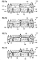
- in schematischen Schnittdarstellungen ein erfindungsgemäßes Pressenwerkzeug und veranschaulicht in mehreren Einzeldarstellungen das damit ausführbare erfindungsgemäße Verfahren zur Herstellung eines komplexen Blechformteils.
- Fig. 1
- in schematic sectional views of a press tool according to the invention and illustrates in several individual representations the process of this invention for producing a complex sheet metal part.
Das Pressenwerkzeug 100 weist ein Werkzeugunterteil 110 und ein Werkzeugoberteil 120 auf. Bei dem Pressenwerkzeug 100 handelt es sich um ein Tiefziehwerkzeug, das in einer nicht dargestellten Presse eingebaut ist, wobei das Werkzeugunterteil 110 auf dem Pressentisch angeordnet und das Werkzeugoberteil 120 am Pressenstößel befestigt ist. Beim Absenken des Pressenstößels führt das Werkzeugoberteil 120 einen Abwärtshub bzw. Arbeitshub mit einer im Wesentlichen kontinuierlichen Abwärtsbewegung aus.The
Das Werkzeugunterteil 110 weist einen Stempel 130, einen den Stempel 130 umgebenden und nach unten verdrängbaren Nieder- bzw. Blechhalter 140 sowie mehrere bewegbare Stempeleinsätze 131, 132 und 133 auf. Die Stempeleinsätze 131, 132 und 133 sind in Stempelausnehmungen angeordnet. Der Stempeleinsatz 131 ist für einen Linienkontakt und die Stempeleinsätze 132 und 133 sind für einen Punktkontakt ausgebildet. Das Werkzeugoberteil 120 weist eine Matrize 150, einen die Matrize 150 umgebenden Matrizenring bzw. Gegenhalter 160 und einen bewegbaren Matrizeneinsatz 151 auf. Das Werkzeug 100 ist für eine Ziehtiefe von mindestens 200 mm ausgelegt. Im Folgenden wird der Ziehvorgang beschrieben.The
In das geöffnete Werkzeug 100 wird ein Blech M in Gestalt einer ebenen Blechplatine (Formplatine) eingelegt und das Werkzeug 100 wird durch Abwärtsbewegen des Pressenstößels bzw. des Werkzeugoberteils 120 geschlossen. Hierbei wird das Blech M in seinem Randbereich zwischen dem gegenüber der Matrize 150 voreilenden Matrizenring 160 und dem Niederhalter 140 eingeklemmt, wie in
Bei weiterem Abwärtshub des Werkzeugoberteils 120 verdrängt der Matrizenring 160 den Niederhalter 140 nach unten. D. h., der Niederhalter 140 wird gemeinsam mit dem Matrizenring 160 nach unten bewegt und bewegt sich hierbei relativ zum feststehenden Stempel 130. (Der Niederhalter 140 kann in an und für sich bekannter Weise durch ein zur Presse oder zum Werkzeug 100 gehörendes Ziehkissen oder dergleichen abgestützt sein, wie mit den dargestellten Federn veranschaulicht.) Hierbei wird das Blech M über die ausgefahrenen Stempeleinsätze 131, 132 und 133 gezogen, wobei im Blech M lokale Materialbevorratungen erzeugt werden. Dies ist in
Gleichzeitig wird mithilfe des mittleren Stempeleinsatzes 131 und dem gegenüberliegenden Matrizeneinsatz 151 eine Designkante mit kleinem Radius in das Blech M eingeformt, wozu der Stempeleinsatz 131 und der Matrizeneinsatz 151 stirnseitig mit korrespondierenden Formungsabschnitten ausgebildet sind. Auch der Matrizeneinsatz 151 ist bspw. mittels Gasdruckfeder federnd gelagert, wie mit der symbolisch dargestellten Feder veranschaulicht.At the same time, by means of the
Bei weiterem Abwärtshub des Werkzeugoberteils 120 werden der Matrizenring 160 und der Niederhalter 140 schließlich bis zu ihrem unteren Totpunkt bewegt, wie in
Das Zurückbewegen bzw. Einfahren der Stempeleinsätze 131, 132 und 133 erfolgt durch eine mechanische Zwangskopplung mit dem Niederhalter 140. Hierzu sind die Stempeleinsätze 131, 132 und 133 bspw. an einem Rahmen oder einer Tragplatte 180 befestigt, der bzw. die beim Abwärtsbewegen des Niederhalters 140 ab einer bestimmten Niederhalterposition (bzw. ab einer definierten Ziehwegposition) mittels am Niederhalter 140 angeordneter Mitnehmer 190 mitgenommen bzw. mitbewegt wird. Der Rahmen 180 ist bspw. an der zum Werkzeugunterteil 110 gehörenden Grundplatte (nicht gezeigt) federnd abgestützt, wie mit den dargestellten Federn veranschaulicht.The moving back or retraction of the punch inserts 131, 132 and 133 is effected by a mechanical positive coupling with the hold-down 140. For this purpose, the punch inserts 131, 132 and 133, for example, attached to a frame or a
Wenn der Niederhalter 140 seinen unteren Totpunkt erreicht hat (siehe
Durch weiteres Abwärtsbewegen des Pressenstößels bzw. des Werkzeugoberteils 120 wird nun noch die nachlaufende Matrize 150 bis zu ihrem unteren Totpunkt bewegt, wobei das Blech M bzw. das Blechformteil noch im Mittenbereich fertig ausgeformt wird (im Außenbereich ist die Umformung bereits abgeschlossen). D. h., der Matrizenring 160 erreicht zuerst seinen unteren Totpunkt, dann läuft die Matrize 150 noch bis zu ihrem unteren Totpunkt weiter und formt dabei den Mittenbereich aus. Wegen der randseitigen Klemmung des Blechs M zwischen dem Matrizenring 160 und dem Niederhalter 140 sowie zwischen dem Matrizenring 160 und dem Stempel 130 kann kein oder kaum Blechmaterial von außen nach innen, d. h. zum Mittenbereich, nachfließen, so dass das Blech M lediglich unter Ausnutzung der zuvor mithilfe der Stempeleinsätze 131, 132 und 133 erzeugten lokalen Materialbevorratungen zwischen der Matrize 150 und dem Stempel 130 prägeartig fertig ausgeformt wird, wobei der federnd gelagerte Matrizeneinsatz 151 zurückweicht bzw. nach oben verdrängt wird. Alternativ kann vorgesehen sein, dass der mittlere Stempeleinsatz 131 nicht zurückbewegt wird und somit weiterhin gegen das Blech M bzw. gegen den Matrizeneinsatz 151 drückt.As a result of further downward movement of the press ram or of the
Claims (10)
dadurch gekennzeichnet, dass
die Ziehtiefe wenigstens 200 mm, bevorzugt wenigstens 250 mm und insbesondere wenigstens 300 mm beträgt.Method according to claim 1,
characterized in that
the drawing depth is at least 200 mm, preferably at least 250 mm and in particular at least 300 mm.
dadurch gekennzeichnet, dass
die Stempeleinsätze (131, 132, 133) durch mechanische Kopplung mit dem Niederhalter (140) zurückbewegt werden.Method according to claim 1 or 2,
characterized in that
the punch inserts (131, 132, 133) are moved back by mechanical coupling with the blank holder (140).
dadurch gekennzeichnet, dass
die Stempeleinsätze (131, 132, 133) asynchron zurückbewegt werden.A method according to any one of the preceding claims;
characterized in that
the punch inserts (131, 132, 133) are moved back asynchronously.
dadurch gekennzeichnet, dass
mit wenigstens einem der Stempeleinsätze (131) eine Designkante mit kleinem Radius erzeugt wird.A method according to any one of the preceding claims;
characterized in that
with at least one of the punch inserts (131) a design edge with a small radius is generated.
zwischen dem Niederhalter (140) und wenigstens einem der Stempeleinsätze (131, 132, 133) eine mechanische Kopplung besteht, durch die der betreffende Stempeleinsatz (131, 132, 133) beim Verdrängen des Niederhalters (140) aktiv zurückbewegt wird.Press tool (100), in particular deep-drawing tool, for producing a complex sheet-metal shaped part, with
a mechanical coupling exists between the hold-down device (140) and at least one of the punch inserts (131, 132, 133), by means of which the relevant punch insert (131, 132, 133) is actively moved back when the hold-down device (140) is displaced.
dadurch gekennzeichnet, dass
wenigstens einer der Stempeleinsätze (131, 132, 133), insbesondere der mit dem Niederhalter (140) gekoppelte Stempeleinsatz (131, 132, 133), zusätzlich federnd gelagert ist.Press tool (100) according to claim 6,
characterized in that
at least one of the punch inserts (131, 132, 133), in particular the punch insert (131, 132, 133) coupled to the hold-down device (140), is additionally spring-mounted.
dadurch gekennzeichnet, dass
wenigstens einer der Stempeleinsätze (132, 133) für einen Punktkontakt mit dem umzuformenden Blech (M) ausgebildet ist.Press tool (100) according to claim 6 or 7,
characterized in that
at least one of the punch inserts (132, 133) is designed for point contact with the sheet (M) to be formed.
dadurch gekennzeichnet, dass
wenigstens einer der Stempeleinsätze (131) für einen Linienkontakt mit dem umzuformenden Blech (M) ausgebildet ist, insbesondere zur Ausformung einer Designkante mit kleinem Radius.Press tool (100) according to one of the preceding claims 6 to 8,
characterized in that
at least one of the punch inserts (131) is designed for line contact with the sheet (M) to be formed, in particular for forming a design edge with a small radius.
dadurch gekennzeichnet, dass
die Matrize (150) wenigstens einen bewegbaren Matrizeneinsatz (151) aufweist, der einem Stempeleinsatz (131), insbesondere zur Ausformung einer Designkante, gegenüberliegt.A press tool (100) according to any one of the preceding claims 6 to 9,
characterized in that
the die (150) has at least one movable die insert (151) facing a punch insert (131), in particular for forming a design edge.
Applications Claiming Priority (1)
| Application Number | Priority Date | Filing Date | Title |
|---|---|---|---|
| DE102016005902.8A DE102016005902B3 (en) | 2016-05-13 | 2016-05-13 | Method and press tool for producing a complex sheet metal part with high draw depth |
Publications (3)
| Publication Number | Publication Date |
|---|---|
| EP3243578A2 true EP3243578A2 (en) | 2017-11-15 |
| EP3243578A3 EP3243578A3 (en) | 2017-11-22 |
| EP3243578B1 EP3243578B1 (en) | 2018-10-03 |
Family
ID=58672257
Family Applications (1)
| Application Number | Title | Priority Date | Filing Date |
|---|---|---|---|
| EP17000777.7A Active EP3243578B1 (en) | 2016-05-13 | 2017-05-05 | Method and press tool for producing a complex sheet metal part with high draw depth |
Country Status (5)
| Country | Link |
|---|---|
| US (1) | US10646911B2 (en) |
| EP (1) | EP3243578B1 (en) |
| JP (1) | JP6370437B2 (en) |
| CN (1) | CN107363147B (en) |
| DE (1) | DE102016005902B3 (en) |
Families Citing this family (6)
| Publication number | Priority date | Publication date | Assignee | Title |
|---|---|---|---|---|
| JP6721544B2 (en) * | 2017-06-28 | 2020-07-15 | 株式会社神戸製鋼所 | Method for manufacturing press-formed products |
| CN108856513A (en) * | 2018-07-08 | 2018-11-23 | 苏州华吉威自动化设备有限公司 | A kind of bend punching die |
| JP6670409B1 (en) * | 2019-03-11 | 2020-03-18 | マレリ株式会社 | Press device and press method |
| JP7111063B2 (en) * | 2019-06-04 | 2022-08-02 | Jfeスチール株式会社 | Press molding equipment |
| DE102021100281B3 (en) | 2021-01-11 | 2022-05-05 | Audi Aktiengesellschaft | Forming tool and method for operating a forming tool |
| FR3122589B1 (en) * | 2021-05-06 | 2023-04-21 | Psa Automobiles Sa | Stamping press tool for stamping a sheet metal blank and corresponding stamping process. |
Citations (1)
| Publication number | Priority date | Publication date | Assignee | Title |
|---|---|---|---|---|
| DE102010045281A1 (en) | 2010-08-31 | 2012-03-01 | Giw Gesellschaft Für Innovative Werkzeugsysteme Mbh | Method for reshaping metal sheet for housing structure of e.g. tailgate of passenger car, involves defining material stock and carrying out complete development in region of pre-tensioned workpiece before supplementary drawing step |
Family Cites Families (23)
| Publication number | Priority date | Publication date | Assignee | Title |
|---|---|---|---|---|
| JPS5731417A (en) * | 1980-08-05 | 1982-02-19 | Toyota Motor Corp | Deep drawing method |
| DD160956A3 (en) * | 1981-01-14 | 1984-07-11 | Schwarzenberg Waschgeraete | METHOD FOR PRODUCING THOROUGH BROADCAST PARTS |
| JPS6038622U (en) * | 1983-08-25 | 1985-03-18 | トヨタ自動車株式会社 | Drawing type structure |
| JPH08206746A (en) * | 1995-01-30 | 1996-08-13 | Isuzu Motors Ltd | Deep drawing device |
| US5600991A (en) * | 1995-02-10 | 1997-02-11 | Ogihara America Corporation | Stretch controlled forming mechanism and method for forming multiple gauge welded blanks |
| US5941110A (en) * | 1997-05-12 | 1999-08-24 | Northern University | Adaptive method and apparatus for forming tailor welded blanks |
| DE19842750B4 (en) * | 1998-09-18 | 2005-06-09 | Audi Ag | Method and production of deep-drawn hollow parts and drawing tool |
| JP2007098443A (en) * | 2005-10-05 | 2007-04-19 | Toyota Motor Corp | Press forming method and press forming apparatus |
| DE102006005964B3 (en) * | 2006-02-08 | 2007-07-19 | Benteler Automobiltechnik Gmbh | Manufacturing process for vehicle component involves making process groove in plate and pressing at least one edge against support to press out groove later |
| JP2007268608A (en) * | 2006-03-08 | 2007-10-18 | Kobe Steel Ltd | Press-forming method of aluminum alloy sheet and press device |
| JP2007326112A (en) * | 2006-06-06 | 2007-12-20 | Hiroshima Pref Gov | Press forming method |
| DE112007002428T5 (en) * | 2006-10-17 | 2009-09-17 | Honda Motor Co., Ltd. | Press working method and press working apparatus |
| CN101164715B (en) * | 2006-10-18 | 2010-08-11 | 宝山钢铁股份有限公司 | Unsymmetrical stretching forming mould capable of inducing plate material to rebound |
| JP4922037B2 (en) * | 2007-03-28 | 2012-04-25 | 株式会社神戸製鋼所 | Aluminum alloy sheet press forming method and press forming apparatus |
| DE102007050580A1 (en) * | 2007-10-23 | 2009-04-30 | Gerd Reitter | Plate i.e. sheet metal plate shaping method for producing e.g. beer barrel, in mechanical press, involves applying reformation strength at internal area of plate against effective direction of deformation strength after deformation of area |
| CN101195142A (en) | 2007-12-26 | 2008-06-11 | 陕西科技大学 | Mold and shaping technique for metal sheet material deep-drawing cup shell |
| MX2011003594A (en) * | 2008-10-07 | 2011-04-27 | Nippon Steel Corp | Metallic press-formed piece crack determining method, apparatus, program and recording medium. |
| JP2010167480A (en) * | 2009-01-26 | 2010-08-05 | Honda Motor Co Ltd | Press-forming die and press-forming method |
| JP5416498B2 (en) * | 2009-07-23 | 2014-02-12 | 本田技研工業株式会社 | Method and apparatus for forming tailored blank plate |
| KR20120062273A (en) * | 2010-12-06 | 2012-06-14 | 현대자동차주식회사 | Press system |
| CN202224531U (en) * | 2011-09-30 | 2012-05-23 | 联伟汽车零部件(重庆)有限公司 | Drawing die for processing parts made of high-tension material |
| MX2016004731A (en) * | 2013-10-24 | 2016-07-18 | Nippon Steel & Sumitomo Metal Corp | Device for manufacturing and method for manufacturing component with hat-shaped cross-sectional surface. |
| CN105013918A (en) | 2015-07-02 | 2015-11-04 | 奇瑞汽车股份有限公司 | Complicated surface plate drawing mold and control method thereof |
-
2016
- 2016-05-13 DE DE102016005902.8A patent/DE102016005902B3/en not_active Expired - Fee Related
-
2017
- 2017-05-05 EP EP17000777.7A patent/EP3243578B1/en active Active
- 2017-05-12 CN CN201710332944.2A patent/CN107363147B/en active Active
- 2017-05-12 US US15/593,758 patent/US10646911B2/en active Active
- 2017-05-15 JP JP2017096110A patent/JP6370437B2/en active Active
Patent Citations (1)
| Publication number | Priority date | Publication date | Assignee | Title |
|---|---|---|---|---|
| DE102010045281A1 (en) | 2010-08-31 | 2012-03-01 | Giw Gesellschaft Für Innovative Werkzeugsysteme Mbh | Method for reshaping metal sheet for housing structure of e.g. tailgate of passenger car, involves defining material stock and carrying out complete development in region of pre-tensioned workpiece before supplementary drawing step |
Also Published As
| Publication number | Publication date |
|---|---|
| EP3243578A3 (en) | 2017-11-22 |
| JP6370437B2 (en) | 2018-08-08 |
| CN107363147A (en) | 2017-11-21 |
| EP3243578B1 (en) | 2018-10-03 |
| US10646911B2 (en) | 2020-05-12 |
| JP2017202525A (en) | 2017-11-16 |
| DE102016005902B3 (en) | 2017-06-29 |
| CN107363147B (en) | 2019-02-19 |
| US20170326612A1 (en) | 2017-11-16 |
Similar Documents
| Publication | Publication Date | Title |
|---|---|---|
| EP3243578B1 (en) | Method and press tool for producing a complex sheet metal part with high draw depth | |
| DE102009003668B4 (en) | Device and method for producing at least partially closed profiles or semi-finished products from a circuit board | |
| DE102013103612A1 (en) | Working and upsetting tool for producing high-volume half-shells | |
| EP2987566B1 (en) | Apparatus and method for calibrating cut surfaces of punched or fineblanked parts having burr | |
| DE102012100230B4 (en) | Apparatus and method for the production of shell parts | |
| EP2701862B1 (en) | Method and device for producing flanged drawn parts with simultaneous trimming | |
| DE112011102050T5 (en) | Manufacturing method and manufacturing apparatus for hub-shaped disc-shaped member | |
| DE102006007224A1 (en) | Method and device for producing a cutout or opening in the wall of a formed by the hydroforming process component | |
| EP2701861A1 (en) | Method and device for producing flangeless drawn parts | |
| EP2686161B1 (en) | Drawing press having two couplable rams | |
| DE19842750B4 (en) | Method and production of deep-drawn hollow parts and drawing tool | |
| DE102009005261A1 (en) | Process for producing a complex sheet metal part | |
| DE102005024378B4 (en) | Method for incremental forming of thin-walled workpieces and device | |
| DE10334483B4 (en) | Method and drawing tool for producing a sheet metal part from a circuit board | |
| DE102016116758A1 (en) | Method and device for producing shaped, in particular flange-shaped, sheet-metal components | |
| DE102005045727B4 (en) | Deep drawing process and thermoforming machine | |
| DE102010018534A1 (en) | Device for molding a workpiece | |
| DE19649629C2 (en) | Flexible tool for hydroforming a sheet | |
| DE102010062977A1 (en) | Deep-drawing and/or stretching tool for forming metal sheet material for chassis panel of motor vehicle, has coil in upper and/or lower tool unit to cut sheet material before, during or after formation of sheet material along cutting line | |
| DE102017102356B3 (en) | Method and device for producing a collar on a workpiece | |
| EP2353745B1 (en) | Tool and method for producing can bodies | |
| DE60300340T2 (en) | Device for press forming | |
| DE10016804B4 (en) | Method and device for producing components from a deep-drawn board | |
| DE102004031290A1 (en) | Tilting system for a crimping device | |
| DE10030792C2 (en) | Multi-stage press, in particular cross transport press, with hydraulic closing device |
Legal Events
| Date | Code | Title | Description |
|---|---|---|---|
| PUAI | Public reference made under article 153(3) epc to a published international application that has entered the european phase |
Free format text: ORIGINAL CODE: 0009012 |
|
| STAA | Information on the status of an ep patent application or granted ep patent |
Free format text: STATUS: THE APPLICATION HAS BEEN PUBLISHED |
|
| PUAL | Search report despatched |
Free format text: ORIGINAL CODE: 0009013 |
|
| AK | Designated contracting states |
Kind code of ref document: A2 Designated state(s): AL AT BE BG CH CY CZ DE DK EE ES FI FR GB GR HR HU IE IS IT LI LT LU LV MC MK MT NL NO PL PT RO RS SE SI SK SM TR |
|
| AX | Request for extension of the european patent |
Extension state: BA ME |
|
| AK | Designated contracting states |
Kind code of ref document: A3 Designated state(s): AL AT BE BG CH CY CZ DE DK EE ES FI FR GB GR HR HU IE IS IT LI LT LU LV MC MK MT NL NO PL PT RO RS SE SI SK SM TR |
|
| AX | Request for extension of the european patent |
Extension state: BA ME |
|
| RIC1 | Information provided on ipc code assigned before grant |
Ipc: B21D 22/26 20060101ALI20171016BHEP Ipc: B21D 22/22 20060101AFI20171016BHEP |
|
| STAA | Information on the status of an ep patent application or granted ep patent |
Free format text: STATUS: REQUEST FOR EXAMINATION WAS MADE |
|
| 17P | Request for examination filed |
Effective date: 20180522 |
|
| RBV | Designated contracting states (corrected) |
Designated state(s): AL AT BE BG CH CY CZ DE DK EE ES FI FR GB GR HR HU IE IS IT LI LT LU LV MC MK MT NL NO PL PT RO RS SE SI SK SM TR |
|
| GRAP | Despatch of communication of intention to grant a patent |
Free format text: ORIGINAL CODE: EPIDOSNIGR1 |
|
| STAA | Information on the status of an ep patent application or granted ep patent |
Free format text: STATUS: GRANT OF PATENT IS INTENDED |
|
| INTG | Intention to grant announced |
Effective date: 20180718 |
|
| GRAS | Grant fee paid |
Free format text: ORIGINAL CODE: EPIDOSNIGR3 |
|
| GRAA | (expected) grant |
Free format text: ORIGINAL CODE: 0009210 |
|
| STAA | Information on the status of an ep patent application or granted ep patent |
Free format text: STATUS: THE PATENT HAS BEEN GRANTED |
|
| AK | Designated contracting states |
Kind code of ref document: B1 Designated state(s): AL AT BE BG CH CY CZ DE DK EE ES FI FR GB GR HR HU IE IS IT LI LT LU LV MC MK MT NL NO PL PT RO RS SE SI SK SM TR |
|
| REG | Reference to a national code |
Ref country code: GB Ref legal event code: FG4D Free format text: NOT ENGLISH |
|
| REG | Reference to a national code |
Ref country code: CH Ref legal event code: EP Ref country code: AT Ref legal event code: REF Ref document number: 1048058 Country of ref document: AT Kind code of ref document: T Effective date: 20181015 |
|
| REG | Reference to a national code |
Ref country code: IE Ref legal event code: FG4D Free format text: LANGUAGE OF EP DOCUMENT: GERMAN Ref country code: DE Ref legal event code: R096 Ref document number: 502017000221 Country of ref document: DE |
|
| REG | Reference to a national code |
Ref country code: NL Ref legal event code: MP Effective date: 20181003 |
|
| REG | Reference to a national code |
Ref country code: LT Ref legal event code: MG4D |
|
| PG25 | Lapsed in a contracting state [announced via postgrant information from national office to epo] |
Ref country code: NL Free format text: LAPSE BECAUSE OF FAILURE TO SUBMIT A TRANSLATION OF THE DESCRIPTION OR TO PAY THE FEE WITHIN THE PRESCRIBED TIME-LIMIT Effective date: 20181003 |
|
| PG25 | Lapsed in a contracting state [announced via postgrant information from national office to epo] |
Ref country code: ES Free format text: LAPSE BECAUSE OF FAILURE TO SUBMIT A TRANSLATION OF THE DESCRIPTION OR TO PAY THE FEE WITHIN THE PRESCRIBED TIME-LIMIT Effective date: 20181003 Ref country code: HR Free format text: LAPSE BECAUSE OF FAILURE TO SUBMIT A TRANSLATION OF THE DESCRIPTION OR TO PAY THE FEE WITHIN THE PRESCRIBED TIME-LIMIT Effective date: 20181003 Ref country code: PL Free format text: LAPSE BECAUSE OF FAILURE TO SUBMIT A TRANSLATION OF THE DESCRIPTION OR TO PAY THE FEE WITHIN THE PRESCRIBED TIME-LIMIT Effective date: 20181003 Ref country code: LV Free format text: LAPSE BECAUSE OF FAILURE TO SUBMIT A TRANSLATION OF THE DESCRIPTION OR TO PAY THE FEE WITHIN THE PRESCRIBED TIME-LIMIT Effective date: 20181003 Ref country code: IS Free format text: LAPSE BECAUSE OF FAILURE TO SUBMIT A TRANSLATION OF THE DESCRIPTION OR TO PAY THE FEE WITHIN THE PRESCRIBED TIME-LIMIT Effective date: 20190203 Ref country code: BG Free format text: LAPSE BECAUSE OF FAILURE TO SUBMIT A TRANSLATION OF THE DESCRIPTION OR TO PAY THE FEE WITHIN THE PRESCRIBED TIME-LIMIT Effective date: 20190103 Ref country code: FI Free format text: LAPSE BECAUSE OF FAILURE TO SUBMIT A TRANSLATION OF THE DESCRIPTION OR TO PAY THE FEE WITHIN THE PRESCRIBED TIME-LIMIT Effective date: 20181003 Ref country code: LT Free format text: LAPSE BECAUSE OF FAILURE TO SUBMIT A TRANSLATION OF THE DESCRIPTION OR TO PAY THE FEE WITHIN THE PRESCRIBED TIME-LIMIT Effective date: 20181003 Ref country code: NO Free format text: LAPSE BECAUSE OF FAILURE TO SUBMIT A TRANSLATION OF THE DESCRIPTION OR TO PAY THE FEE WITHIN THE PRESCRIBED TIME-LIMIT Effective date: 20190103 Ref country code: CZ Free format text: LAPSE BECAUSE OF FAILURE TO SUBMIT A TRANSLATION OF THE DESCRIPTION OR TO PAY THE FEE WITHIN THE PRESCRIBED TIME-LIMIT Effective date: 20181003 |
|
| PG25 | Lapsed in a contracting state [announced via postgrant information from national office to epo] |
Ref country code: RS Free format text: LAPSE BECAUSE OF FAILURE TO SUBMIT A TRANSLATION OF THE DESCRIPTION OR TO PAY THE FEE WITHIN THE PRESCRIBED TIME-LIMIT Effective date: 20181003 Ref country code: GR Free format text: LAPSE BECAUSE OF FAILURE TO SUBMIT A TRANSLATION OF THE DESCRIPTION OR TO PAY THE FEE WITHIN THE PRESCRIBED TIME-LIMIT Effective date: 20190104 Ref country code: PT Free format text: LAPSE BECAUSE OF FAILURE TO SUBMIT A TRANSLATION OF THE DESCRIPTION OR TO PAY THE FEE WITHIN THE PRESCRIBED TIME-LIMIT Effective date: 20190203 Ref country code: AL Free format text: LAPSE BECAUSE OF FAILURE TO SUBMIT A TRANSLATION OF THE DESCRIPTION OR TO PAY THE FEE WITHIN THE PRESCRIBED TIME-LIMIT Effective date: 20181003 Ref country code: SE Free format text: LAPSE BECAUSE OF FAILURE TO SUBMIT A TRANSLATION OF THE DESCRIPTION OR TO PAY THE FEE WITHIN THE PRESCRIBED TIME-LIMIT Effective date: 20181003 |
|
| REG | Reference to a national code |
Ref country code: DE Ref legal event code: R097 Ref document number: 502017000221 Country of ref document: DE |
|
| PG25 | Lapsed in a contracting state [announced via postgrant information from national office to epo] |
Ref country code: DK Free format text: LAPSE BECAUSE OF FAILURE TO SUBMIT A TRANSLATION OF THE DESCRIPTION OR TO PAY THE FEE WITHIN THE PRESCRIBED TIME-LIMIT Effective date: 20181003 Ref country code: IT Free format text: LAPSE BECAUSE OF FAILURE TO SUBMIT A TRANSLATION OF THE DESCRIPTION OR TO PAY THE FEE WITHIN THE PRESCRIBED TIME-LIMIT Effective date: 20181003 |
|
| PLBE | No opposition filed within time limit |
Free format text: ORIGINAL CODE: 0009261 |
|
| STAA | Information on the status of an ep patent application or granted ep patent |
Free format text: STATUS: NO OPPOSITION FILED WITHIN TIME LIMIT |
|
| PG25 | Lapsed in a contracting state [announced via postgrant information from national office to epo] |
Ref country code: SK Free format text: LAPSE BECAUSE OF FAILURE TO SUBMIT A TRANSLATION OF THE DESCRIPTION OR TO PAY THE FEE WITHIN THE PRESCRIBED TIME-LIMIT Effective date: 20181003 Ref country code: SM Free format text: LAPSE BECAUSE OF FAILURE TO SUBMIT A TRANSLATION OF THE DESCRIPTION OR TO PAY THE FEE WITHIN THE PRESCRIBED TIME-LIMIT Effective date: 20181003 Ref country code: EE Free format text: LAPSE BECAUSE OF FAILURE TO SUBMIT A TRANSLATION OF THE DESCRIPTION OR TO PAY THE FEE WITHIN THE PRESCRIBED TIME-LIMIT Effective date: 20181003 Ref country code: RO Free format text: LAPSE BECAUSE OF FAILURE TO SUBMIT A TRANSLATION OF THE DESCRIPTION OR TO PAY THE FEE WITHIN THE PRESCRIBED TIME-LIMIT Effective date: 20181003 |
|
| 26N | No opposition filed |
Effective date: 20190704 |
|
| PG25 | Lapsed in a contracting state [announced via postgrant information from national office to epo] |
Ref country code: SI Free format text: LAPSE BECAUSE OF FAILURE TO SUBMIT A TRANSLATION OF THE DESCRIPTION OR TO PAY THE FEE WITHIN THE PRESCRIBED TIME-LIMIT Effective date: 20181003 |
|
| PG25 | Lapsed in a contracting state [announced via postgrant information from national office to epo] |
Ref country code: MC Free format text: LAPSE BECAUSE OF FAILURE TO SUBMIT A TRANSLATION OF THE DESCRIPTION OR TO PAY THE FEE WITHIN THE PRESCRIBED TIME-LIMIT Effective date: 20181003 |
|
| REG | Reference to a national code |
Ref country code: BE Ref legal event code: MM Effective date: 20190531 |
|
| PG25 | Lapsed in a contracting state [announced via postgrant information from national office to epo] |
Ref country code: LU Free format text: LAPSE BECAUSE OF NON-PAYMENT OF DUE FEES Effective date: 20190505 |
|
| PG25 | Lapsed in a contracting state [announced via postgrant information from national office to epo] |
Ref country code: TR Free format text: LAPSE BECAUSE OF FAILURE TO SUBMIT A TRANSLATION OF THE DESCRIPTION OR TO PAY THE FEE WITHIN THE PRESCRIBED TIME-LIMIT Effective date: 20181003 |
|
| PG25 | Lapsed in a contracting state [announced via postgrant information from national office to epo] |
Ref country code: IE Free format text: LAPSE BECAUSE OF NON-PAYMENT OF DUE FEES Effective date: 20190505 |
|
| PG25 | Lapsed in a contracting state [announced via postgrant information from national office to epo] |
Ref country code: BE Free format text: LAPSE BECAUSE OF NON-PAYMENT OF DUE FEES Effective date: 20190531 |
|
| PG25 | Lapsed in a contracting state [announced via postgrant information from national office to epo] |
Ref country code: CH Free format text: LAPSE BECAUSE OF NON-PAYMENT OF DUE FEES Effective date: 20200531 Ref country code: LI Free format text: LAPSE BECAUSE OF NON-PAYMENT OF DUE FEES Effective date: 20200531 |
|
| PG25 | Lapsed in a contracting state [announced via postgrant information from national office to epo] |
Ref country code: CY Free format text: LAPSE BECAUSE OF FAILURE TO SUBMIT A TRANSLATION OF THE DESCRIPTION OR TO PAY THE FEE WITHIN THE PRESCRIBED TIME-LIMIT Effective date: 20181003 |
|
| PG25 | Lapsed in a contracting state [announced via postgrant information from national office to epo] |
Ref country code: MT Free format text: LAPSE BECAUSE OF FAILURE TO SUBMIT A TRANSLATION OF THE DESCRIPTION OR TO PAY THE FEE WITHIN THE PRESCRIBED TIME-LIMIT Effective date: 20181003 Ref country code: HU Free format text: LAPSE BECAUSE OF FAILURE TO SUBMIT A TRANSLATION OF THE DESCRIPTION OR TO PAY THE FEE WITHIN THE PRESCRIBED TIME-LIMIT; INVALID AB INITIO Effective date: 20170505 |
|
| PG25 | Lapsed in a contracting state [announced via postgrant information from national office to epo] |
Ref country code: MK Free format text: LAPSE BECAUSE OF FAILURE TO SUBMIT A TRANSLATION OF THE DESCRIPTION OR TO PAY THE FEE WITHIN THE PRESCRIBED TIME-LIMIT Effective date: 20181003 |
|
| P01 | Opt-out of the competence of the unified patent court (upc) registered |
Effective date: 20230530 |
|
| REG | Reference to a national code |
Ref country code: AT Ref legal event code: MM01 Ref document number: 1048058 Country of ref document: AT Kind code of ref document: T Effective date: 20220505 |
|
| PG25 | Lapsed in a contracting state [announced via postgrant information from national office to epo] |
Ref country code: AT Free format text: LAPSE BECAUSE OF NON-PAYMENT OF DUE FEES Effective date: 20220505 |
|
| PGFP | Annual fee paid to national office [announced via postgrant information from national office to epo] |
Ref country code: FR Payment date: 20230523 Year of fee payment: 7 Ref country code: DE Payment date: 20230531 Year of fee payment: 7 |
|
| PGFP | Annual fee paid to national office [announced via postgrant information from national office to epo] |
Ref country code: GB Payment date: 20230526 Year of fee payment: 7 |