EP3243482B1 - Method for guiding dental implant plan, apparatus for same, and recording medium therefor - Google Patents
Method for guiding dental implant plan, apparatus for same, and recording medium therefor Download PDFInfo
- Publication number
- EP3243482B1 EP3243482B1 EP15875546.2A EP15875546A EP3243482B1 EP 3243482 B1 EP3243482 B1 EP 3243482B1 EP 15875546 A EP15875546 A EP 15875546A EP 3243482 B1 EP3243482 B1 EP 3243482B1
- Authority
- EP
- European Patent Office
- Prior art keywords
- implant
- area
- setting
- tooth
- boundary
- Prior art date
- Legal status (The legal status is an assumption and is not a legal conclusion. Google has not performed a legal analysis and makes no representation as to the accuracy of the status listed.)
- Active
Links
- 238000000034 method Methods 0.000 title claims description 32
- 239000004053 dental implant Substances 0.000 title claims description 17
- 239000007943 implant Substances 0.000 claims description 250
- 238000004364 calculation method Methods 0.000 claims description 58
- 210000000988 bone and bone Anatomy 0.000 claims description 21
- 230000001054 cortical effect Effects 0.000 claims description 20
- 210000004195 gingiva Anatomy 0.000 claims description 17
- 210000004086 maxillary sinus Anatomy 0.000 claims description 17
- 210000000276 neural tube Anatomy 0.000 claims description 16
- 230000008878 coupling Effects 0.000 claims description 2
- 238000010168 coupling process Methods 0.000 claims description 2
- 238000005859 coupling reaction Methods 0.000 claims description 2
- 238000001514 detection method Methods 0.000 claims description 2
- 208000008312 Tooth Loss Diseases 0.000 description 27
- 238000003780 insertion Methods 0.000 description 15
- 230000037431 insertion Effects 0.000 description 12
- 230000003287 optical effect Effects 0.000 description 8
- 230000008569 process Effects 0.000 description 7
- 238000002591 computed tomography Methods 0.000 description 6
- 238000004590 computer program Methods 0.000 description 5
- 210000002455 dental arch Anatomy 0.000 description 5
- 238000002513 implantation Methods 0.000 description 5
- 230000000694 effects Effects 0.000 description 3
- 210000001847 jaw Anatomy 0.000 description 3
- 210000000214 mouth Anatomy 0.000 description 3
- 238000012545 processing Methods 0.000 description 3
- 210000004763 bicuspid Anatomy 0.000 description 2
- 238000010586 diagram Methods 0.000 description 2
- 239000000284 extract Substances 0.000 description 2
- 230000006870 function Effects 0.000 description 2
- 230000004048 modification Effects 0.000 description 2
- 238000012986 modification Methods 0.000 description 2
- 238000004422 calculation algorithm Methods 0.000 description 1
- 239000000969 carrier Substances 0.000 description 1
- 238000004891 communication Methods 0.000 description 1
- 239000000470 constituent Substances 0.000 description 1
- 238000012937 correction Methods 0.000 description 1
- 230000003247 decreasing effect Effects 0.000 description 1
- 238000010191 image analysis Methods 0.000 description 1
- 230000005389 magnetism Effects 0.000 description 1
- 239000003550 marker Substances 0.000 description 1
- 210000002050 maxilla Anatomy 0.000 description 1
- 210000004400 mucous membrane Anatomy 0.000 description 1
- 230000008520 organization Effects 0.000 description 1
- 210000003695 paranasal sinus Anatomy 0.000 description 1
- 230000003239 periodontal effect Effects 0.000 description 1
- 230000004044 response Effects 0.000 description 1
- 239000004065 semiconductor Substances 0.000 description 1
- 238000001356 surgical procedure Methods 0.000 description 1
- 230000009897 systematic effect Effects 0.000 description 1
Images


Classifications
-
- A—HUMAN NECESSITIES
- A61—MEDICAL OR VETERINARY SCIENCE; HYGIENE
- A61C—DENTISTRY; APPARATUS OR METHODS FOR ORAL OR DENTAL HYGIENE
- A61C13/00—Dental prostheses; Making same
- A61C13/0003—Making bridge-work, inlays, implants or the like
- A61C13/0004—Computer-assisted sizing or machining of dental prostheses
-
- A—HUMAN NECESSITIES
- A61—MEDICAL OR VETERINARY SCIENCE; HYGIENE
- A61C—DENTISTRY; APPARATUS OR METHODS FOR ORAL OR DENTAL HYGIENE
- A61C19/00—Dental auxiliary appliances
- A61C19/04—Measuring instruments specially adapted for dentistry
-
- A—HUMAN NECESSITIES
- A61—MEDICAL OR VETERINARY SCIENCE; HYGIENE
- A61C—DENTISTRY; APPARATUS OR METHODS FOR ORAL OR DENTAL HYGIENE
- A61C8/00—Means to be fixed to the jaw-bone for consolidating natural teeth or for fixing dental prostheses thereon; Dental implants; Implanting tools
-
- G—PHYSICS
- G06—COMPUTING; CALCULATING OR COUNTING
- G06F—ELECTRIC DIGITAL DATA PROCESSING
- G06F3/00—Input arrangements for transferring data to be processed into a form capable of being handled by the computer; Output arrangements for transferring data from processing unit to output unit, e.g. interface arrangements
- G06F3/01—Input arrangements or combined input and output arrangements for interaction between user and computer
- G06F3/048—Interaction techniques based on graphical user interfaces [GUI]
- G06F3/0484—Interaction techniques based on graphical user interfaces [GUI] for the control of specific functions or operations, e.g. selecting or manipulating an object, an image or a displayed text element, setting a parameter value or selecting a range
- G06F3/04842—Selection of displayed objects or displayed text elements
-
- G—PHYSICS
- G06—COMPUTING; CALCULATING OR COUNTING
- G06T—IMAGE DATA PROCESSING OR GENERATION, IN GENERAL
- G06T7/00—Image analysis
- G06T7/0002—Inspection of images, e.g. flaw detection
- G06T7/0012—Biomedical image inspection
-
- G—PHYSICS
- G06—COMPUTING; CALCULATING OR COUNTING
- G06T—IMAGE DATA PROCESSING OR GENERATION, IN GENERAL
- G06T7/00—Image analysis
- G06T7/10—Segmentation; Edge detection
- G06T7/11—Region-based segmentation
-
- G—PHYSICS
- G06—COMPUTING; CALCULATING OR COUNTING
- G06T—IMAGE DATA PROCESSING OR GENERATION, IN GENERAL
- G06T7/00—Image analysis
- G06T7/70—Determining position or orientation of objects or cameras
-
- G—PHYSICS
- G06—COMPUTING; CALCULATING OR COUNTING
- G06T—IMAGE DATA PROCESSING OR GENERATION, IN GENERAL
- G06T2207/00—Indexing scheme for image analysis or image enhancement
- G06T2207/30—Subject of image; Context of image processing
- G06T2207/30004—Biomedical image processing
- G06T2207/30036—Dental; Teeth
Definitions
- the present invention relates to a method of guiding a dental implant treatment plan, a device and a recording medium therefore. More specifically, the present invention relates to a method of guiding dental implant planning that provides a guide to dentist in software for the implant planning, a device and a recording medium therefore.
- the implant is to replace a lost tooth, and the procedures to establish appropriate implant planning on implant insertion position and direction, size and type of implant is a crucial process for successful treatment.
- US 2013/316298 A1 discloses an apparatus for supporting dental implantation surgery.
- the apparatus includes CT (computed tomography) image acquiring means for acquiring a three-dimensional CT image of jaws of an object; a first setting section for setting a reference site of the jaws and an implantation position of a gum in the jaws in the three-dimensional CT image, an implant being implanted at the implantation position of the gum; a three-dimensional optical image acquiring section for acquiring a three-dimensional optical image of an inside of an oral cavity of the object; a second setting section for setting a position of the reference site in the three-dimensional optical image by recognizing a shape of the reference site in the three-dimensional optical image; and a control section for controlling a position of a surgical tool to the implantation position in the oral cavity, based on a relationship between the position of the reference site and the implantation position of the gum in the three-dimensional CT image and the position of the reference site in the three-dimensional optical image.
- CT computed tomography
- the program user to perform implant treatment depends mainly on the experience and the sense to establish position of prosthesis such as the fixture, the abutment, virtual crown, and therefore the deviation of the implant planning is made by individual to individual so as to raise strong doubts concerning the reliability of the result of the implant treatment.
- the conventional software has not provided any guide for the establishment of the implant planning so for users to modify the implant plan repeatedly, which causes to increase the time required and the complexity of procedures for the implant planning.
- a planning method that can guide a user is required to reduce the reliance on user experience and to simplify and decrease the time that takes for establishing the plan.
- An object of the present invention which is to solve aforementioned problems of having a high dependence on user experience and taking a long time when planning implant treatment, is to provide a guide to dentist in software for the implant planning, and a device and a recording medium therefore.
- the present invention provides a method as defined in the appended independent claim 1.
- the step of calculating the implant area comprises calculating the implant area by applying a boundary surface as a criterion, wherein the boundary surface is determined based on at least one of the elements among occlusal surfaces, adj acent teeth in the region where the tooth has been lost, gingiva, cortical bones, neural tubes, and a maxillary sinus.
- the above method may further comprises receiving a selection of at least one implant area among the implant areas displayed on the teeth image by a user input unit; determining a position where a recommended implant object or a user preference implant object is inserted into the selected implant area; and displaying an image where the implant object has been inserted automatically in the determined position.
- the present invention provides a device as defined in the appended independent claim 4.
- the implant area calculation unit may calculate the implant area by applying a boundary surface as a criterion, and the boundary surface may be determined based on at least one of the elements among occlusal surfaces, adjacent teeth in the region where the tooth has been lost, gingiva, cortical bones, neural tubes, and a maxillary sinus.
- the implant area calculation unit calculates the implant area by setting first boundary surfaces, second boundary surface, and third boundary surface, and the first boundary surfaces are set based on boundaries between the left and right adjacent teeth of the region, the second boundary surface is set based on occlusal surface, and the third boundary surface is set based on position of neural tubes in lower jaw or maxillary sinus in upper jaw.
- the implant area calculation unit can calculate position of each of the implant objects comprising at least one among a fixture, an abutment, and the virtual crown.
- the implant area calculation unit comprises: a virtual crown area calculation unit that calculates a virtual crown position area by setting the first boundary surfaces based on boundaries with the left and right adjacent teeth of the region, setting the second boundary surface based on occlusal surface, and setting the third boundary surface based on gingiva junction; an abutment area calculation unit that calculates an abutment position area by setting the first boundary surfaces based on boundaries with left and right adjacent teeth of the region, setting the second boundary surface based on gingiva junction and setting the third boundary surface based on the boundary of cortical bone; and a fixture area calculation unit that calculates a fixture position area by setting the first boundary surfaces based on boundaries with left and right adjacent teeth of the area, setting the second boundary surface based on a boundary of cortical bone, and setting the third boundary surface based on the position of neural tube in lower jaw or the position of maxillary sinus in upper jaw.
- the implant area calculation unit can comprise a virtual crown area calculation unit that calculates a virtual crown position area by setting the first boundary surfaces based on boundaries with the left and right adjacent teeth of the region, setting the second boundary surface based on occlusal surface, and setting the third boundary surface based on gingiva junction; an abutment area calculation unit that calculates an abutment position area by setting the first boundary surfaces based on boundaries with left and right adjacent teeth of the region, setting the second boundary surface based on gingiva junction and setting the third boundary surface based on the boundary of cortical bone; and a fixture area calculation unit that calculates a fixture position area by setting the first boundary surfaces based on boundaries determined by at least one reference information among reference distance information between an adjacent tooth of the region and a fixture, reference distance information between adjacent fixtures, reference distance information between an adjacent tooth of the region and center of a fixture, and reference distance information between centers of adjacent fixtures, setting the second boundary surface based on a boundary of cortical bone, and setting the third boundary surface based on the position of neural tube in lower jaw
- the virtual crown calculation unit and the abutment area calculation unit calculate each the virtual crown position area and the abutment position area by setting the fourth boundary surfaces based on boundaries between buccal side and lingual side of maximum convexity of the left and right adjacent teeth crown of the region, and the fixture area calculation unit calculates the fixture position area by setting the fourth boundary surfaces based on boundaries of buccal side and lingual side cortical bone to calculate the implant area in 3-dimensions.
- the plan guide providing unit can display the implant position area separated by each implant object including at least one among a fixture, an abutment and a virtual crown.
- the device may comprise an user input unit that receives the selection of at least one implant area among the implant areas displayed on the teeth image, and an implant planning unit that determines a position within the selected implant area through the user input unit, where recommended object or user preferred implant object is to be inserted automatically, wherein the planning guide providing unit displays an image where an implant object is inserted in the position determined by the implant planning unit.
- plan guide providing displays the arrangement of tooth icons coupling one-to-one to tooth area of the teeth image, but make a distinction between the display of the tooth icons coupled to the missing tooth area and the display of the tooth icons coupled to the existing tooth area in the arrangement, so it can improve intuitive insight and increase ease of operation for users.
- the user can increase the accuracy of treatment by providing the opportunity to verify the procedure itself during treatment.
- FIG. 1 is a block diagram for the implant planning guide device 100 according to an embodiment of the present invention.
- the implant planning guide device 100 comprises the lost region detecting unit 10, the implant area calculation unit 20, the planning guide providing unit 30, the user input unit 40 and the implant planning unit 50.
- the lost region detecting unit 10 detects the region where the tooth has been lost in teeth image. Tooth loss region can be detected by extracting the upper and lower dental arches and analyzing the extracted dental arches. For example, the lost region detecting unit 10 will be able to detect the tooth loss region on the dental arches with the various image analysis algorithm based on the gray scale value of the image.
- the implant area calculation unit 20 calculates implant area where the implant is to be placed on the tooth loss region detected from the lost region detecting unit 10.
- Implant area where the implant can be placed, means an area where the implant objects that form the implant, for example, a fixture, the abutment, and virtual crown can be placed.
- the actual implant placing area in the detected loss region is to be selected by the user and only the implant area in the selected implant placing area can be implemented to be calculated.
- the implant area calculation unit 20 can calculate the implant area on the basis of the boundary surfaces determined based on at least one of elements among occlusal surface, the adjacent teeth of the tooth loss region, gingiva, cortical bone, neural tube, and maxillary sinus. If the tooth loss region exists in lower jaw, the implant area is calculated on the basis of neural tubes under the tooth loss region. On the other hand, if the tooth loss region exists in upper jaw, the implant area is calculated on the basis of maxillary sinus.
- the occlusal surface is a boundary surface that upper teeth and lower teeth meet and form when closing the mouth
- the gingiva means the pink mucosal tissue covering the alveolar bone in the apical direction from the alveolar
- the cortical bone is the hardest part which is the outermost region of a periodontal bone
- the maxillary sinus is a paranasal sinus in the maxilla.
- calculating the implant position area is based on criteria from boundary surfaces which are established on the basis of the position of the teeth, gingiva, cortical bone, neural tube, maxillary sinus, etc. adjacent to the loss region, as described above, further considering pre-stored information from users and a guide information about object placement position such as the type of each implant object, intraoral position of area where the implant is to be placed, a distance information between adjacent teeth and implant objects, a distance information by each adjacent implant, an implant object reference information, a placement relation information among implant objects etc. More explanation on this will be described in more detail below.
- the implant area calculation unit 20 can calculate the position of the respective implant object or calculate the integrated implant area without dividing implant objects such as the fixture, the virtual crown, abutment and so on that make up the implant.
- the implant area calculation unit 20 can be divided into the virtual crown area calculation unit 21 which calculates the virtual crown position area, the abutment area calculation unit 23 which calculates an abutment position area, and the fixture area calculation unit 25 which calculates a fixture position area.
- the implant area calculation part 20, to calculate positions for each object can use each boundary surface for each object.
- the implant area calculation unit 20 not only can calculate implant area in a 2-dimensions based on the left and right boundary surfaces and upper and lower boundary surfaces only, but can calculate in 3-dimensions by applying a front and rear boundary surfaces as additional boundary surfaces, that is the buccal-lingual boundary surfaces.
- the planning guide providing unit 30 displays the implant area calculated by the implant area calculation unit 20 on the tooth image. Besides, the planning guide providing unit 30 displays a variety of images to provide guidance to the user on the implant planning process, including the user interface image representing the tooth loss region graphically by using the tooth icon. For this purpose, the planning guide providing unit 30 can be implemented using various display means for displaying images according to the implant planning process.
- the user input unit 40 receives the selection from user for the implant area among the implant areas displayed by the planning guide providing unit 30, and receives a variety of information required in the implant planning process.
- the implant planning unit 50 determines the implant position area among the implant areas displayed on the teeth image where the implant object is to be inserted automatically, wherein the implant object is preferred by user or recommended in the selected implant position area via the user input unit 40.
- the planning guide providing unit 30 displays an image of the implant object inserted in the implant auto-insertion area which is determined by the implant planning unit 50.
- the implant planning unit 50 performs the processes in the overall planning and implant planning modifications.
- FIG. 2 is a flowchart showing the implant planning guide method according to an embodiment of the present invention.
- FIG. 2 the systematic operations of the constituent of implant planning guide device 100 will be explained.
- the lost region detecting unit 10 detects the region where the tooth has been lost in teeth image in step S10.
- the tooth loss region can be detected by extracting upper and lower dental arches in the teeth image and analyzing the extracted dental arches.
- the planning guide providing unit 30 displays the position of the detected tooth loss region with coupled tooth icon arrangement, which can help the user's intuitive understanding and ease of operation.
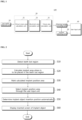
- FIG. 3 illustrates an example of a screen displaying the detected tooth loss regions and the icon coupled to the region.
- the teeth icon arrangement which is one-to-one coupled with the tooth area in the panorama image is displayed, and the tooth number is given to each tooth icon.
- the planning guide providing unit 30 make a distinction between the display of the tooth icons with tooth number coupled to the missing tooth area and the display of the tooth icons coupled to the existing tooth area in the arrangement with marker such as different color, brightness, tooth icon, etc. which helps user intuitively grasp the tooth loss regions. Furthermore, in the case due to problems of resolution or clarity the user may also experience difficulties to distinguish or select the specific teeth in the teeth image, when the user selects or operates the tooth icon, the planning guide proving unit 30 can perform operations for the tooth area corresponding the selected or operated icon on the teeth image, which increases the user's convenience.
- teeth icons shown in FIG. 3 which is exemplary shape, may be implemented in a variety of shapes such as including tooth root.
- the implant area calculation unit 20 calculates the implant area based on the boundary surface which is determined based on a variety of factors and information for tooth loss region selected through the user input unit 40 or all the detected tooth loss regions in step S20.
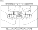
- FIG. 4 and FIG. 5 are drawings to explain an example of calculating the implant position area.
- the implant area calculation unit 20 sets the first boundary surfaces (a, b) based on the left and right boundaries with adjacent teeth (401, 403) in the tooth loss region, sets the second boundary surface (c) based on the occlusal surface, and sets the third boundary surface (d) based on the position of neural tube in lower jaw or the position of maxillary sinus in upper jaw to calculate the implant area (R).
- the implant area calculation unit 20 follows implant area calculation basically as stated above. However, it can get some information of the area criteria through the user input unit 40 in advance, apply the inputted area criteria to the calculated implant area as stated above, and to calculate the final implant area through the adjustment.
- the implant area can apply the position of the tooth loss region and the type of the inserted fixture and adjust it by predetermined length from the boundary surface to calculate the final implant area.
- the degree of the adjustment from the boundary surface may be applied differently to calculate the final implant area.
- the implant area calculation unit 20 may extract the left and right boundary surfaces (a, b) and the upper and lower boundary surfaces (c, d) and calculate the implant area(R) in 2-dimensions in FIG. 4 . However, it can comprise the 4th boundary surfaces as depicted in FIG. 5 and calculate the implant area(R) in 3-dimensions.
- the implant area calculation unit 20 extracts the fourth boundary surfaces (e, f) based on boundaries between buccal side and lingual side of maximum convexity of the left and right adjacent teeth crown of the region and adds one axis information to the implant area calculated in FIG. 4 to show an example of calculating the implant area (R) in 3-dimensions.
- the implant area (R) can be defined as a cube, and at this time, the left and right boundary surfaces (a, b) are each side of the cube, the upper and lower boundary surfaces (c, d) are top and bottom of each cube, buccal / lingual boundary surfaces (e, f) corresponds to the front and back surfaces of each of the cube.
- the implant area calculation unit 20 can calculate implant areas for the respective implant object that forms the implant such as a fixture, a virtual crown, an abutment, respectively.
- FIG. 6 is a drawing to explain an example of the reference for calculating the implant areas corresponding to each implant object.
- an example for calculating implant areas by each object will be considered.
- orders of each object whose implant area is calculated may be changed.
- the virtual crown area calculation unit 21 sets the first boundary surfaces (a1, b1) based on the boundaries between the left and right adjacent teeth (601, 603) of the loss region, sets the second boundary surface (c1) based on the occlusal surface, and sets the third boundary surface (d1) based on the boundary of the adjacent gingiva in the tooth loss region to calculate the position area of the virtual crown (R1).
- the abutment area calculation unit 23 sets the first boundary surfaces (a2, b2) based on boundaries with left and right adjacent teeth (501, 603), sets the second boundary surface (c2) based on the boundary of adjacent gingiva in the tooth loss region, and sets the third boundary surface (d2) based on the boundary of the cortical bone to calculate the abutment position area (R2).
- the fixture area calculation unit 25 sets the first boundary surfaces (a3, b3) based on the boundaries with the left and right adjacent teeth (601, 603) in the tooth loss region, sets the second boundary surface (c3) based on the boundary of the cortical bone, and sets the third boundary surface (d3) based on the position of neural tube in lower jaw or the position of maxillary sinus in upper jaw, to calculate the fixture position area (R3).
- the implant areas (R1, R2, R3) can be calculated in 2-dimensions for each implant object, but as described above referring to FIG. 5 , the implant areas (R1, R2, R3) can be calculated in 3-dimentions for each implant object.
- the virtual crown area calculation unit 21 and the abutment area calculation unit 23 can calculate the virtual crown position area (R1) and abutment position area (R2) in 3-dimensions by setting the fourth boundaries based on boundaries between buccal side and lingual side of maximum convexity of the left and right adjacent teeth crown of the tooth loss region.
- the fixture area calculation unit 25 by setting the fourth boundaries based on the cortical boundaries of the buccal side and lingual side, can calculate the fixture position area (R3) in 3-dimensions.
- the fixture area calculation unit 25 sets the first boundary surfaces (a3, b3) based on boundaries with the left and right adjacent teeth (601, 603) in the tooth loss region to calculate the fixture position area (R3), but in consideration that the position where the fixture is implanted is narrower than the width of the position area (R1) of the virtual crown, the fixture position area (R3) can be calculated by reflecting the specific information about the fixture position as illustrated in FIG. 7 .
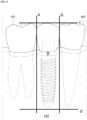
- FIG. 7 is a drawing to explain another example for calculating the fixture position area.
- the fixture area calculation unit 25 saves in advance reference information and sets the first boundary surfaces (a3, b3) based on boundaries determined from the reference information to calculate the fixture position area (R3), wherein the reference information comprises the reference distance (D1) between an adjacent tooth (tooth 35) and the fixture of the tooth loss region (36 tooth area), the reference distance (D2) between adjacent fixtures, the reference distance (D3) between an adjacent tooth (35 tooth) of the tooth loss region (36 tooth area) and the center of the fixture, the reference distance (D4) between the centers of the adjacent fixtures, etc.
- the reference information comprises the reference distance (D1) between an adjacent tooth (tooth 35) and the fixture of the tooth loss region (36 tooth area), the reference distance (D2) between adjacent fixtures, the reference distance (D3) between an adjacent tooth (35 tooth) of the tooth loss region (36 tooth area) and the center of the fixture, the reference distance (D4) between the centers of the adjacent fixtures, etc.
- the fixture position area may be calculated.
- D1 of 3.5mm, D2 of 4mm, D3 of 5.5mm, D4 of 8mm the fixture position area may be calculated.
- the stored reference information recommended procedure guide information though common in the industry or input data demonstrated empirically by users may be used, and the reference information can be set respectively depending on the teeth position and the fixture type applied.
- the planning guide providing unit 30 marks the implant area calculated in 2 or 3 dimensions through the above stated steps on the teeth image with using a predetermined mark in step S30.
- FIG. 8 and FIG. 9 is an example of a screen where the planning guide providing unit 30 displays the calculated implant areas.
- the planning guide providing unit 30 can display the implant areas integrally for all the implant objects as depicted in FIG. 8 or can display each implant area for the respective implant object as depicted in FIG. 9 .
- the implant area of the implant object which is selected by dragging can be displayed, separated from unselected implant areas of the implant object.
- the planning guide providing unit 30 can display the calculated implant area as shown FIG. 8 and FIG. 9 in 2-dimensions, or display the calculated implant area depending on the user's selection or as needed in 3-dimensions.
- FIG. 8 and FIG. 9 illustrate the screen which the calculated implant area displays on 2-dimensional teeth panorama image.
- 3-dimensional implant position area it can be displayed on 3-dimensional image such as CT image, scan image etc.
- the implant area When the implant area is displayed, it receives the implant position area where implant is to be placed through the user input unit 40.
- the implant planning unit 50 determines the position where the recommended implant object or user's preferred implant object is inserted automatically in step S50. At this time, information about recommended implant object and user's preferred implant object can be pre-stored. Besides, it can be received from outside or can be obtained by input from the user whenever determining insertion position.
- the implant planning unit 50 can determine auto-inserted position based on pre-stored information entered in advance or the guide information about the object insertion position comprising a kind of each implant object, the position of the selected area, the distance information between adjacent teeth and objects, the reference information by each adjacent implant object, the reference information depending on insertion position, the insertion information among implant objects.
- specific auto-insertion position can be determined depending on the length of the object, and specific auto-inserted position can be determined differently according to the type of the object, the teeth, e.g. the molars, premolars. Furthermore, it can be determined to reflect the standard guide information according to each object insertion position and preferred position information according to user's experience, such as the fixture is placed in the center of the virtual crown, the abutment is placed in a position to endure the weight of a virtual crown.
- the planning guide providing unit 30 displays the image with the inserted implant object in position corresponding to the implant object auto-insertion position determined by the implant planning unit 50.
- the planning guide providing unit 30, after displaying the image with the inserted implant object displays the information on the inserted implant and its inventory status by interlocking with ERP(Enterprise Resource Plan) program, which will be able to proceed the implant plan process afterward on the basis of this.
- ERP Enterprise Resource Plan
- the implant planning unit 50 can provide the user with an automatic insertion mode of the implant object alternatively, and if the user did not select the automatic insertion mode, the user can insert implant object directly in the area marked by the planning guide providing unit 30 through the user input unit 40, and it may be implemented to provide notification if exceeding the area according to the automatic insertion criteria, such as the example described.
- the implant planning unit 50 can provide the correction function for the object inserted automatically or manually in response to user input through the user input unit 40. In this case, but also to modify each by implant object, it can increase user's convenience by modifying the grouped implant objects together optionally. Also, the implant planning unit 50, when invading structure which should not be intruded such as sinus neural tube or maxillary sinus etc. during the modification of an object or modified beyond the area of the placement guide information stored in advance, may provide notification about this.
- the implant guide method according to an embodiment of the present invention is written in a program that can be run on the computer and is implemented in a variety of recording medium such as magnetic storage media, optical recording media, digital storage media.
- the implant guide device 100 according to the embodiment of the invention, the method, and the recording medium, the implant insertion position, which was determined only depending on user's experience and knowledge, can draw various factors within oral as standard boundary applied, can reduce the deviation of the procedure by providing guide information about it by providing guide information about this, so that a user can also provide a means to verify the procedure itself in the process.
- Implementations of the various techniques described herein area digital electronic circuitry, or computer hardware, firmware, software, or may be implemented in a combination of them. Implementations can be implemented by a data processing device, for example, a programmable processor, a computer, or for processing by the operation of a plurality of computers, or to control the operation, the computer program product, i.e. the information carrier, for example, machine-readable apparatus (computer readable medium) or a radio signal.
- the computer program as stated above can be recorded in a programming language of any type, including a substituted or interpret compiled language, as a stand-alone program or as a module, component, subroutine, or in the computing environment, it may be deployed in any form, including as appropriate, including the use of other units. Computer program can be distributed across one or more computer or a number of sites to be processed on multiple computers at one site, and can be connected by a communication network.
- processors suitable for the processing of the computer program comprise as an example, includes both general and special purpose microprocessors, and more than one processors of any kind of digital computer.
- a processor may receive commands or data from read-only memory or random-access memory or both.
- the computer can include more than one memory device saving at least one processor and commands and data which executes commands. For example, it includes magnetism, magnetic-optical disks, or optical disks, or transmitting this data or combining both, or it can receive or transmit data or combine both.
- semiconductor memory device includes hard disks, floppy disks, and magnetic tape, such as magnetic media, CD-ROM (Compact Disk Read Only Memory), DVD (Digital Video disk) and the like optical recording media, floptical disk, such as magnetooptical media, ROM (Read Only Memory), RAM (Random Access memory), comprises a flash memory, EPROM (Erasable Programmable ROM), EEPROM (Electrically Erasable Programmable ROM) etc.
- Processor and memory can be added or included by special purpose logic circuitry.
Landscapes
- Health & Medical Sciences (AREA)
- Engineering & Computer Science (AREA)
- General Health & Medical Sciences (AREA)
- Life Sciences & Earth Sciences (AREA)
- Oral & Maxillofacial Surgery (AREA)
- Dentistry (AREA)
- Veterinary Medicine (AREA)
- Animal Behavior & Ethology (AREA)
- Epidemiology (AREA)
- Public Health (AREA)
- Theoretical Computer Science (AREA)
- Physics & Mathematics (AREA)
- General Physics & Mathematics (AREA)
- Computer Vision & Pattern Recognition (AREA)
- Orthopedic Medicine & Surgery (AREA)
- General Engineering & Computer Science (AREA)
- Quality & Reliability (AREA)
- Radiology & Medical Imaging (AREA)
- Nuclear Medicine, Radiotherapy & Molecular Imaging (AREA)
- Medical Informatics (AREA)
- Human Computer Interaction (AREA)
- Biophysics (AREA)
- Biomedical Technology (AREA)
- Dental Prosthetics (AREA)
- Dental Tools And Instruments Or Auxiliary Dental Instruments (AREA)
Description
- The present invention relates to a method of guiding a dental implant treatment plan, a device and a recording medium therefore. More specifically, the present invention relates to a method of guiding dental implant planning that provides a guide to dentist in software for the implant planning, a device and a recording medium therefore.
- The implant is to replace a lost tooth, and the procedures to establish appropriate implant planning on implant insertion position and direction, size and type of implant is a crucial process for successful treatment.
-
US 2013/316298 A1 discloses an apparatus for supporting dental implantation surgery. The apparatus includes CT (computed tomography) image acquiring means for acquiring a three-dimensional CT image of jaws of an object; a first setting section for setting a reference site of the jaws and an implantation position of a gum in the jaws in the three-dimensional CT image, an implant being implanted at the implantation position of the gum; a three-dimensional optical image acquiring section for acquiring a three-dimensional optical image of an inside of an oral cavity of the object; a second setting section for setting a position of the reference site in the three-dimensional optical image by recognizing a shape of the reference site in the three-dimensional optical image; and a control section for controlling a position of a surgical tool to the implantation position in the oral cavity, based on a relationship between the position of the reference site and the implantation position of the gum in the three-dimensional CT image and the position of the reference site in the three-dimensional optical image. - Conventionally, the program user to perform implant treatment depends mainly on the experience and the sense to establish position of prosthesis such as the fixture, the abutment, virtual crown, and therefore the deviation of the implant planning is made by individual to individual so as to raise strong doubts concerning the reliability of the result of the implant treatment.
- Also, the conventional software has not provided any guide for the establishment of the implant planning so for users to modify the implant plan repeatedly, which causes to increase the time required and the complexity of procedures for the implant planning.
- Therefore, a planning method that can guide a user is required to reduce the reliance on user experience and to simplify and decrease the time that takes for establishing the plan.
- An object of the present invention, which is to solve aforementioned problems of having a high dependence on user experience and taking a long time when planning implant treatment, is to provide a guide to dentist in software for the implant planning, and a device and a recording medium therefore.
- In order to achieve the above object, the present invention provides a method as defined in the appended
independent claim 1. - In the method, the step of calculating the implant area comprises calculating the implant area by applying a boundary surface as a criterion, wherein the boundary surface is determined based on at least one of the elements among occlusal surfaces, adj acent teeth in the region where the tooth has been lost, gingiva, cortical bones, neural tubes, and a maxillary sinus.
- The above method may further comprises receiving a selection of at least one implant area among the implant areas displayed on the teeth image by a user input unit; determining a position where a recommended implant object or a user preference implant object is inserted into the selected implant area; and displaying an image where the implant object has been inserted automatically in the determined position.
- Also, in order to achieve the above object, the present invention provides a device as defined in the appended independent claim 4.
- In the device, the implant area calculation unit may calculate the implant area by applying a boundary surface as a criterion, and the boundary surface may be determined based on at least one of the elements among occlusal surfaces, adjacent teeth in the region where the tooth has been lost, gingiva, cortical bones, neural tubes, and a maxillary sinus.
- Also, in the device, the implant area calculation unit calculates the implant area by setting first boundary surfaces, second boundary surface, and third boundary surface, and the first boundary surfaces are set based on boundaries between the left and right adjacent teeth of the region, the second boundary surface is set based on occlusal surface, and the third boundary surface is set based on position of neural tubes in lower jaw or maxillary sinus in upper jaw.
- Meanwhile, the implant area calculation unit can calculate position of each of the implant objects comprising at least one among a fixture, an abutment, and the virtual crown.
- To calculate each position for implant objects, the implant area calculation unit comprises: a virtual crown area calculation unit that calculates a virtual crown position area by setting the first boundary surfaces based on boundaries with the left and right adjacent teeth of the region, setting the second boundary surface based on occlusal surface, and setting the third boundary surface based on gingiva junction; an abutment area calculation unit that calculates an abutment position area by setting the first boundary surfaces based on boundaries with left and right adjacent teeth of the region, setting the second boundary surface based on gingiva junction and setting the third boundary surface based on the boundary of cortical bone; and a fixture area calculation unit that calculates a fixture position area by setting the first boundary surfaces based on boundaries with left and right adjacent teeth of the area, setting the second boundary surface based on a boundary of cortical bone, and setting the third boundary surface based on the position of neural tube in lower jaw or the position of maxillary sinus in upper jaw.
- Or, the implant area calculation unit can comprise a virtual crown area calculation unit that calculates a virtual crown position area by setting the first boundary surfaces based on boundaries with the left and right adjacent teeth of the region, setting the second boundary surface based on occlusal surface, and setting the third boundary surface based on gingiva junction; an abutment area calculation unit that calculates an abutment position area by setting the first boundary surfaces based on boundaries with left and right adjacent teeth of the region, setting the second boundary surface based on gingiva junction and setting the third boundary surface based on the boundary of cortical bone; and a fixture area calculation unit that calculates a fixture position area by setting the first boundary surfaces based on boundaries determined by at least one reference information among reference distance information between an adjacent tooth of the region and a fixture, reference distance information between adjacent fixtures, reference distance information between an adjacent tooth of the region and center of a fixture, and reference distance information between centers of adjacent fixtures, setting the second boundary surface based on a boundary of cortical bone, and setting the third boundary surface based on the position of neural tube in lower jaw or the position of maxillary sinus in upper jaw.
- When calculating position for respective implant object as stated above, the virtual crown calculation unit and the abutment area calculation unit calculate each the virtual crown position area and the abutment position area by setting the fourth boundary surfaces based on boundaries between buccal side and lingual side of maximum convexity of the left and right adjacent teeth crown of the region, and the fixture area calculation unit calculates the fixture position area by setting the fourth boundary surfaces based on boundaries of buccal side and lingual side cortical bone to calculate the implant area in 3-dimensions.
- On the other hand, the plan guide providing unit can display the implant position area separated by each implant object including at least one among a fixture, an abutment and a virtual crown.
- In addition, the device may comprise an user input unit that receives the selection of at least one implant area among the implant areas displayed on the teeth image, and an implant planning unit that determines a position within the selected implant area through the user input unit, where recommended object or user preferred implant object is to be inserted automatically, wherein the planning guide providing unit displays an image where an implant object is inserted in the position determined by the implant planning unit.
- The plan guide providing displays the arrangement of tooth icons coupling one-to-one to tooth area of the teeth image, but make a distinction between the display of the tooth icons coupled to the missing tooth area and the display of the tooth icons coupled to the existing tooth area in the arrangement, so it can improve intuitive insight and increase ease of operation for users.
- In addition, the above stated object can be also achieved by a computer-readable recording medium storing a program to execute the method of dental implant planning.
- As stated above, according to the present invention, by providing a guide to the area that is the object to implant position, there are the effects of reducing the complexity of the implant plan and decreasing procedure deviations depending on users.
- Also, according to the present invention, the user can increase the accuracy of treatment by providing the opportunity to verify the procedure itself during treatment.
-
-
FIG. 1 is a block diagram for implant planning guide device according to an embodiment of the present invention. -
FIG. 2 is a flowchart illustrating procedures of providing the implant treatment planning method according to an embodiment of the present invention. -
FIG. 3 illustrates an example of a screen displaying detected tooth loss regions and the icon coupled to the region; -
FIG. 4 andFIG. 5 are drawings to explain an example of calculating the implant position area; -
FIG. 6 is a drawing to explain an example of the reference for calculating the implant areas corresponding to each implant object. -
FIG. 7 is a drawing to explain another example for calculating the fixture position area. -
FIG. 8 and FIG. 9 is an example of a screen displaying the calculated implant areas. - Hereinafter, with reference to the accompanying drawings, preferred embodiments of the present invention will be described in detail. However, the explanation on the known functions and configurations that may obscure the subject matter of the present invention from the detailed description of the following description and from the accompanying drawings will be omitted. In addition, the same components throughout the drawings are referred to by the same reference numerals as possible which is to be noted.
- The terms used in this specification and claims is not to be construed as limited to dictionary meanings, but can be defined and interpreted based on the meanings and concepts corresponding to technical aspects of the present invention in the principle that inventors define the terms appropriate to the concept of a term to describe his own invention in the best way. Therefore, the present embodiment and the configuration shown in the drawings and described in the specification is merely nothing but a preferable embodiment of the present invention, as not intended to represent all the technical concept of the present invention, so that it should be understood that varied modified embodiments of the present invention can be made in the present application point.
-
FIG. 1 is a block diagram for the implantplanning guide device 100 according to an embodiment of the present invention. Referring toFIG. 1 , the implantplanning guide device 100 comprises the lostregion detecting unit 10, the implantarea calculation unit 20, the planningguide providing unit 30, theuser input unit 40 and theimplant planning unit 50. - The lost
region detecting unit 10 detects the region where the tooth has been lost in teeth image. Tooth loss region can be detected by extracting the upper and lower dental arches and analyzing the extracted dental arches. For example, the lostregion detecting unit 10 will be able to detect the tooth loss region on the dental arches with the various image analysis algorithm based on the gray scale value of the image. - The implant
area calculation unit 20 calculates implant area where the implant is to be placed on the tooth loss region detected from the lostregion detecting unit 10. Implant area, where the implant can be placed, means an area where the implant objects that form the implant, for example, a fixture, the abutment, and virtual crown can be placed. In this case, but also to calculate the implant areas for all the detected tooth loss regions, the actual implant placing area in the detected loss region is to be selected by the user and only the implant area in the selected implant placing area can be implemented to be calculated. - When placing an implant, it should be considered for harmonization of surrounding structures and organization and effects about masticatory movement or aesthetic elements. To this, the implant
area calculation unit 20 can calculate the implant area on the basis of the boundary surfaces determined based on at least one of elements among occlusal surface, the adjacent teeth of the tooth loss region, gingiva, cortical bone, neural tube, and maxillary sinus. If the tooth loss region exists in lower jaw, the implant area is calculated on the basis of neural tubes under the tooth loss region. On the other hand, if the tooth loss region exists in upper jaw, the implant area is calculated on the basis of maxillary sinus. For reference, the occlusal surface is a boundary surface that upper teeth and lower teeth meet and form when closing the mouth, the gingiva means the pink mucosal tissue covering the alveolar bone in the apical direction from the alveolar, the cortical bone is the hardest part which is the outermost region of a periodontal bone, and the maxillary sinus is a paranasal sinus in the maxilla. - Meanwhile, calculating the implant position area is based on criteria from boundary surfaces which are established on the basis of the position of the teeth, gingiva, cortical bone, neural tube, maxillary sinus, etc. adjacent to the loss region, as described above, further considering pre-stored information from users and a guide information about object placement position such as the type of each implant object, intraoral position of area where the implant is to be placed, a distance information between adjacent teeth and implant objects, a distance information by each adjacent implant, an implant object reference information, a placement relation information among implant objects etc. More explanation on this will be described in more detail below.
- In addition, the implant
area calculation unit 20 can calculate the position of the respective implant object or calculate the integrated implant area without dividing implant objects such as the fixture, the virtual crown, abutment and so on that make up the implant. Like this, as the components for calculating insertion position areas by each implant object, the implantarea calculation unit 20 can be divided into the virtual crownarea calculation unit 21 which calculates the virtual crown position area, the abutmentarea calculation unit 23 which calculates an abutment position area, and the fixturearea calculation unit 25 which calculates a fixture position area. The implantarea calculation part 20, to calculate positions for each object, can use each boundary surface for each object. - The implant
area calculation unit 20, not only can calculate implant area in a 2-dimensions based on the left and right boundary surfaces and upper and lower boundary surfaces only, but can calculate in 3-dimensions by applying a front and rear boundary surfaces as additional boundary surfaces, that is the buccal-lingual boundary surfaces. - The planning
guide providing unit 30 displays the implant area calculated by the implantarea calculation unit 20 on the tooth image. Besides, the planningguide providing unit 30 displays a variety of images to provide guidance to the user on the implant planning process, including the user interface image representing the tooth loss region graphically by using the tooth icon. For this purpose, the planningguide providing unit 30 can be implemented using various display means for displaying images according to the implant planning process. - The
user input unit 40 receives the selection from user for the implant area among the implant areas displayed by the planningguide providing unit 30, and receives a variety of information required in the implant planning process. - The
implant planning unit 50 determines the implant position area among the implant areas displayed on the teeth image where the implant object is to be inserted automatically, wherein the implant object is preferred by user or recommended in the selected implant position area via theuser input unit 40. Correspondingly, the planningguide providing unit 30 displays an image of the implant object inserted in the implant auto-insertion area which is determined by theimplant planning unit 50. Besides the above stated decision of implant insertion position area, theimplant planning unit 50 performs the processes in the overall planning and implant planning modifications. -
FIG. 2 is a flowchart showing the implant planning guide method according to an embodiment of the present invention. Hereinafter, referring toFIG. 2 , the systematic operations of the constituent of implantplanning guide device 100 will be explained. - The lost
region detecting unit 10 detects the region where the tooth has been lost in teeth image in step S10. The tooth loss region can be detected by extracting upper and lower dental arches in the teeth image and analyzing the extracted dental arches. The planningguide providing unit 30 displays the position of the detected tooth loss region with coupled tooth icon arrangement, which can help the user's intuitive understanding and ease of operation. -
FIG. 3 illustrates an example of a screen displaying the detected tooth loss regions and the icon coupled to the region. - Referring to
FIG. 3 , the teeth icon arrangement which is one-to-one coupled with the tooth area in the panorama image is displayed, and the tooth number is given to each tooth icon. The planningguide providing unit 30 make a distinction between the display of the tooth icons with tooth number coupled to the missing tooth area and the display of the tooth icons coupled to the existing tooth area in the arrangement with marker such as different color, brightness, tooth icon, etc. which helps user intuitively grasp the tooth loss regions. Furthermore, in the case due to problems of resolution or clarity the user may also experience difficulties to distinguish or select the specific teeth in the teeth image, when the user selects or operates the tooth icon, the planningguide proving unit 30 can perform operations for the tooth area corresponding the selected or operated icon on the teeth image, which increases the user's convenience. - For reference, the teeth icons shown in
FIG. 3 , which is exemplary shape, may be implemented in a variety of shapes such as including tooth root. - When the detection of the tooth loss region is made, the implant
area calculation unit 20 calculates the implant area based on the boundary surface which is determined based on a variety of factors and information for tooth loss region selected through theuser input unit 40 or all the detected tooth loss regions in step S20. -
FIG. 4 andFIG. 5 are drawings to explain an example of calculating the implant position area. - First, referring to
FIG. 4 , the implantarea calculation unit 20 sets the first boundary surfaces (a, b) based on the left and right boundaries with adjacent teeth (401, 403) in the tooth loss region, sets the second boundary surface (c) based on the occlusal surface, and sets the third boundary surface (d) based on the position of neural tube in lower jaw or the position of maxillary sinus in upper jaw to calculate the implant area (R). - On the other hand, the implant
area calculation unit 20 follows implant area calculation basically as stated above. However, it can get some information of the area criteria through theuser input unit 40 in advance, apply the inputted area criteria to the calculated implant area as stated above, and to calculate the final implant area through the adjustment. - In addition, basically based on the calculation basis of the implant area as stated above, it can apply the position of the tooth loss region and the type of the inserted fixture and adjust it by predetermined length from the boundary surface to calculate the final implant area. For example, when tooth loss region is in position of the molars or premolars, in consideration of the characteristics according to the teeth position, the degree of the adjustment from the boundary surface may be applied differently to calculate the final implant area.
- The implant
area calculation unit 20 may extract the left and right boundary surfaces (a, b) and the upper and lower boundary surfaces (c, d) and calculate the implant area(R) in 2-dimensions inFIG. 4 . However, it can comprise the 4th boundary surfaces as depicted inFIG. 5 and calculate the implant area(R) in 3-dimensions. - In
FIG. 5 , the implantarea calculation unit 20 extracts the fourth boundary surfaces (e, f) based on boundaries between buccal side and lingual side of maximum convexity of the left and right adjacent teeth crown of the region and adds one axis information to the implant area calculated inFIG. 4 to show an example of calculating the implant area (R) in 3-dimensions. According toFIG. 5 , the implant area (R) can be defined as a cube, and at this time, the left and right boundary surfaces (a, b) are each side of the cube, the upper and lower boundary surfaces (c, d) are top and bottom of each cube, buccal / lingual boundary surfaces (e, f) corresponds to the front and back surfaces of each of the cube. - Meanwhile, in
FIG. 4 andFIG. 5 , the example was shown for calculating an integrated implant area (R) without considering respective implant object, the implantarea calculation unit 20 can calculate implant areas for the respective implant object that forms the implant such as a fixture, a virtual crown, an abutment, respectively. -
FIG. 6 is a drawing to explain an example of the reference for calculating the implant areas corresponding to each implant object. Hereinafter, referring toFIG. 6 , an example for calculating implant areas by each object will be considered. At this time, orders of each object whose implant area is calculated may be changed. - Looking at the example for calculating a virtual crown position area according to the virtual crown
area calculation unit 21, the virtual crownarea calculation unit 21 sets the first boundary surfaces (a1, b1) based on the boundaries between the left and right adjacent teeth (601, 603) of the loss region, sets the second boundary surface (c1) based on the occlusal surface, and sets the third boundary surface (d1) based on the boundary of the adjacent gingiva in the tooth loss region to calculate the position area of the virtual crown (R1). - The abutment
area calculation unit 23 sets the first boundary surfaces (a2, b2) based on boundaries with left and right adjacent teeth (501, 603), sets the second boundary surface (c2) based on the boundary of adjacent gingiva in the tooth loss region, and sets the third boundary surface (d2) based on the boundary of the cortical bone to calculate the abutment position area (R2). - The fixture
area calculation unit 25 sets the first boundary surfaces (a3, b3) based on the boundaries with the left and right adjacent teeth (601, 603) in the tooth loss region, sets the second boundary surface (c3) based on the boundary of the cortical bone, and sets the third boundary surface (d3) based on the position of neural tube in lower jaw or the position of maxillary sinus in upper jaw, to calculate the fixture position area (R3). - Meanwhile, as depicted in
FIG. 6 , the implant areas (R1, R2, R3) can be calculated in 2-dimensions for each implant object, but as described above referring toFIG. 5 , the implant areas (R1, R2, R3) can be calculated in 3-dimentions for each implant object. - For example, the virtual crown
area calculation unit 21 and the abutmentarea calculation unit 23 can calculate the virtual crown position area (R1) and abutment position area (R2) in 3-dimensions by setting the fourth boundaries based on boundaries between buccal side and lingual side of maximum convexity of the left and right adjacent teeth crown of the tooth loss region. Also, the fixturearea calculation unit 25, by setting the fourth boundaries based on the cortical boundaries of the buccal side and lingual side, can calculate the fixture position area (R3) in 3-dimensions. - Referring to
FIG. 6 in the above example, the fixturearea calculation unit 25 sets the first boundary surfaces (a3, b3) based on boundaries with the left and right adjacent teeth (601, 603) in the tooth loss region to calculate the fixture position area (R3), but in consideration that the position where the fixture is implanted is narrower than the width of the position area (R1) of the virtual crown, the fixture position area (R3) can be calculated by reflecting the specific information about the fixture position as illustrated inFIG. 7 . -
FIG. 7 is a drawing to explain another example for calculating the fixture position area. - Referring to
FIG. 7 , if thetooth 36 andtooth 37 have been lost, the fixturearea calculation unit 25 saves in advance reference information and sets the first boundary surfaces (a3, b3) based on boundaries determined from the reference information to calculate the fixture position area (R3), wherein the reference information comprises the reference distance (D1) between an adjacent tooth (tooth 35) and the fixture of the tooth loss region (36 tooth area), the reference distance (D2) between adjacent fixtures, the reference distance (D3) between an adjacent tooth (35 tooth) of the tooth loss region (36 tooth area) and the center of the fixture, the reference distance (D4) between the centers of the adjacent fixtures, etc. For example, as an example of the reference information, by applying D1 of 3.5mm, D2 of 4mm, D3 of 5.5mm, D4 of 8mm, the fixture position area may be calculated. Above reference information is one example, and as the stored reference information, recommended procedure guide information though common in the industry or input data demonstrated empirically by users may be used, and the reference information can be set respectively depending on the teeth position and the fixture type applied. - The planning
guide providing unit 30 marks the implant area calculated in 2 or 3 dimensions through the above stated steps on the teeth image with using a predetermined mark in step S30. -
FIG. 8 and FIG. 9 is an example of a screen where the planningguide providing unit 30 displays the calculated implant areas. - The planning
guide providing unit 30 can display the implant areas integrally for all the implant objects as depicted inFIG. 8 or can display each implant area for the respective implant object as depicted inFIG. 9 . On the other hand, in case of displaying integrally implant areas as depicted inFIG. 8 , the implant area of the implant object which is selected by dragging can be displayed, separated from unselected implant areas of the implant object. - Meanwhile, the planning
guide providing unit 30 can display the calculated implant area as shownFIG. 8 and FIG. 9 in 2-dimensions, or display the calculated implant area depending on the user's selection or as needed in 3-dimensions.FIG. 8 and FIG. 9 illustrate the screen which the calculated implant area displays on 2-dimensional teeth panorama image. On the other hand, when displaying 3-dimensional implant position area, it can be displayed on 3-dimensional image such as CT image, scan image etc. - When the implant area is displayed, it receives the implant position area where implant is to be placed through the
user input unit 40. - When selection of one or a plurality of implant area is made, the
implant planning unit 50 determines the position where the recommended implant object or user's preferred implant object is inserted automatically in step S50. At this time, information about recommended implant object and user's preferred implant object can be pre-stored. Besides, it can be received from outside or can be obtained by input from the user whenever determining insertion position. - On the other hand, the
implant planning unit 50 can determine auto-inserted position based on pre-stored information entered in advance or the guide information about the object insertion position comprising a kind of each implant object, the position of the selected area, the distance information between adjacent teeth and objects, the reference information by each adjacent implant object, the reference information depending on insertion position, the insertion information among implant objects. - For example, it is principle to determine the auto-inserted position within the area shown by the planning
guide providing unit 30, specific auto-insertion position can be determined depending on the length of the object, and specific auto-inserted position can be determined differently according to the type of the object, the teeth, e.g. the molars, premolars. Furthermore, it can be determined to reflect the standard guide information according to each object insertion position and preferred position information according to user's experience, such as the fixture is placed in the center of the virtual crown, the abutment is placed in a position to endure the weight of a virtual crown. - The planning
guide providing unit 30 displays the image with the inserted implant object in position corresponding to the implant object auto-insertion position determined by theimplant planning unit 50. In addition, the planningguide providing unit 30, after displaying the image with the inserted implant object, displays the information on the inserted implant and its inventory status by interlocking with ERP(Enterprise Resource Plan) program, which will be able to proceed the implant plan process afterward on the basis of this. - Meanwhile, the steps described above may be properly added or modified as needed to be applied. For example, the
implant planning unit 50 can provide the user with an automatic insertion mode of the implant object alternatively, and if the user did not select the automatic insertion mode, the user can insert implant object directly in the area marked by the planningguide providing unit 30 through theuser input unit 40, and it may be implemented to provide notification if exceeding the area according to the automatic insertion criteria, such as the example described. - On the other hand, the
implant planning unit 50 can provide the correction function for the object inserted automatically or manually in response to user input through theuser input unit 40. In this case, but also to modify each by implant object, it can increase user's convenience by modifying the grouped implant objects together optionally. Also, theimplant planning unit 50, when invading structure which should not be intruded such as sinus neural tube or maxillary sinus etc. during the modification of an object or modified beyond the area of the placement guide information stored in advance, may provide notification about this. - On the other hand, the implant guide method according to an embodiment of the present invention is written in a program that can be run on the computer and is implemented in a variety of recording medium such as magnetic storage media, optical recording media, digital storage media.
- As can be seen from the above description, the
implant guide device 100 according to the embodiment of the invention, the method, and the recording medium, the implant insertion position, which was determined only depending on user's experience and knowledge, can draw various factors within oral as standard boundary applied, can reduce the deviation of the procedure by providing guide information about it by providing guide information about this, so that a user can also provide a means to verify the procedure itself in the process. - Implementations of the various techniques described herein area digital electronic circuitry, or computer hardware, firmware, software, or may be implemented in a combination of them. Implementations can be implemented by a data processing device, for example, a programmable processor, a computer, or for processing by the operation of a plurality of computers, or to control the operation, the computer program product, i.e. the information carrier, for example, machine-readable apparatus (computer readable medium) or a radio signal. The computer program as stated above can be recorded in a programming language of any type, including a substituted or interpret compiled language, as a stand-alone program or as a module, component, subroutine, or in the computing environment, it may be deployed in any form, including as appropriate, including the use of other units. Computer program can be distributed across one or more computer or a number of sites to be processed on multiple computers at one site, and can be connected by a communication network.
- Processors suitable for the processing of the computer program comprise as an example, includes both general and special purpose microprocessors, and more than one processors of any kind of digital computer. Generally, a processor may receive commands or data from read-only memory or random-access memory or both. The computer can include more than one memory device saving at least one processor and commands and data which executes commands. For example, it includes magnetism, magnetic-optical disks, or optical disks, or transmitting this data or combining both, or it can receive or transmit data or combine both. Information carriers appropriate for specifying computer program commands or data as an example, semiconductor memory device, for example, includes hard disks, floppy disks, and magnetic tape, such as magnetic media, CD-ROM (Compact Disk Read Only Memory), DVD (Digital Video disk) and the like optical recording media, floptical disk, such as magnetooptical media, ROM (Read Only Memory), RAM (Random Access memory), comprises a flash memory, EPROM (Erasable Programmable ROM), EEPROM (Electrically Erasable Programmable ROM) etc. Processor and memory can be added or included by special purpose logic circuitry.
Claims (15)
- A computer-implemented method of guiding dental implant planning, comprising:detecting (S10) by a computer a region where a tooth has been lost based on a tooth image;calculating (S20) by a computer an implant area where an implant object, which is a part of an implant, is to be placed in the region; anddisplaying (S60) by a computer the implant area on the teeth image by using a pre-determined mark.characterized in thatthe implant area is displayed (S60) separately for each of the implant objects, or the implant areas are displayed (S60) integrally for all the implant objects, andwherein in case that the implant areas are displayed (S60) integrally for all the implant objects, an implant area of an implant object which is selected by dragging is separately displayed (S60) from the implant area of unselected implant objects.
- The method according to claim 1,wherein calculating (S20) the implant area comprises calculating the implant area by applying a boundary surface as a criterion, andwherein the boundary surface is determined based on at least one of the elements among occlusal surfaces, adjacent teeth in the region where the tooth has been lost, gingiva, cortical bones, neural tubes, and a maxillary sinus.
- The method according to claim 1, further comprising:receiving a selection (S40) of at least one implant area among the implant areas displayed on the teeth image by a user input unit (40),determining (S50) a position where a recommended implant object or a user preference implant object is inserted into the selected implant area, anddisplaying (S60) an image where the implant object has been inserted automatically in the determined position.
- A device for guiding dental implant planning, comprising:a lost region detection unit (10) that detects a region where a tooth was lost based on a tooth image,an implant area calculation unit (20) that calculates an implant area where an implant object, which is a part of an implant, is to be placed in the region, anda planning guide providing unit (30) that provides an implant planning guide by displaying the calculated implant position area on the teeth image by using a pre-determined mark,characterized in thatthe planning guide providing unit (30) is configured to display the implant area separated for each of the implant objects, or to display the implant areas integrally for all the implant objects,wherein in case that the planning guide providing unit (30) displays the implant areas integrally for all the implant objects, an implant area of an implant object which is selected by dragging is separately displayed from the implant area of unselected implant objects.
- The device for guiding dental implant planning according to claim 4,wherein the implant area calculation unit (20) calculates the implant area by applying a boundary surface as a criterion, andwherein the boundary surface is determined based on at least one of the elements among occlusal surfaces, adjacent teeth in the region where the tooth has been lost, gingiva, cortical bones, neural tubes, and a maxillary sinus.
- The device for guiding dental implant planning according to claim 4,wherein the implant area calculation unit (20) calculates the implant area by setting first boundary surfaces, second boundary surface, and third boundary surface, andwherein the first boundary surfaces are set based on boundaries between the left and right adjacent teeth of the region, the second boundary surface is set based on occlusal surface, and the third boundary surface is set based on position of neural tubes in lower jaw or maxillary sinus in upper jaw.
- The device for guiding dental implant planning according to claim 6,
wherein the implant area calculation unit (20) calculates the implant area in 3-dimensions by setting the fourth boundary surfaces based on boundaries between buccal side and lingual side of maximum convexity of the left and right adjacent teeth crown of the region. - A device for guiding dental implant planning according to claim 4,
wherein the implant area calculation unit (20) calculates position of each of the implant objects comprising at least one among a fixture, an abutment, and the virtual crown. - The device for guiding dental implant planning according to claim 4,wherein the implant area calculation unit (20) comprises,a virtual crown area calculation unit (21) that calculates a virtual crown position area by setting the first boundary surfaces based on boundaries with the left and right adjacent teeth of the region, setting the second boundary surface based on occlusal surface, and setting the third boundary surface based on gingiva junction;an abutment area calculation unit (23) that calculates an abutment position area by setting the first boundary surfaces based on boundaries with left and right adjacent teeth of the region, setting the second boundary surface based on gingiva junction and setting the third boundary surface based on the boundary of cortical bone; anda fixture area calculation unit (25) that calculates a fixture position area by setting the first boundary surfaces based on boundaries with left and right adjacent teeth of the area, setting the second boundary surface based on a boundary of cortical bone, and setting the third boundary surface based on the position of neural tube in lower jaw or the position of maxillary sinus in upper jaw.
- The device for guiding dental implant planning according to claim 4,wherein the implant area calculation unit (20) comprises,a virtual crown area calculation unit (21) that calculates a virtual crown position area by setting the first boundary surfaces based on boundaries with the left and right adjacent teeth of the region, setting the second boundary surface based on occlusal surface, and setting the third boundary surface based on gingiva junction;an abutment area calculation unit (23) that calculates an abutment position area by setting the first boundary surfaces based on boundaries with left and right adjacent teeth of the region, setting the second boundary surface based on gingiva junction and setting the third boundary surface based on the boundary of cortical bone; anda fixture area calculation unit (25) that calculates a fixture position area by setting the first boundary surfaces based on boundaries determined by at least one reference information among reference distance information between an adjacent tooth of the region and a fixture, reference distance information between adjacent fixtures, reference distance information between an adjacent tooth of the region and center of a fixture, and reference distance information between centers of adjacent fixtures, setting the second boundary surface based on a boundary of cortical bone, and setting the third boundary surface based on the position of neural tube in lower jaw or the position of maxillary sinus in upper jaw.
- The device for guiding dental implant planning according to claim 9 or claim 10,
wherein the virtual crown calculation unit (21) and the abutment area calculation unit (23) calculate each the virtual crown position area and the abutment position area by setting the fourth boundary surfaces based on boundaries between buccal side and lingual side of maximum convexity of the left and right adjacent teeth crown of the region, and the fixture area calculation unit (25) calculates the fixture position area by setting the fourth boundary surfaces based on boundaries of buccal side and lingual side cortical bone to calculate the implant area in 3-dimensions. - A device for guiding dental implant planning according to claim 4, further comprising:an user input unit (40) that receives the selection of at least one implant area among the implant areas displayed on the teeth image; andan implant planning unit (50) that determines a position within the selected implant area through the user input unit, where recommended object or user preferred implant object is to be inserted automatically,wherein the planning guide providing unit (30) displays an image where an implant object is inserted in the position determined by the implant planning unit.
- The device for guiding dental implant planning according to claim 12,wherein the implant planning unit (50) determines the auto-inserted position within the implant area,wherein the implant area is calculated based on user input information and pre-stored criteria information comprising at least one among criteria distance information between the implant object and adjacent tooth, criteria distance information between the same kinds of the adjacent implant objects, reference information on the implant object for the implant area, and insertion-relation information of the implant objects,wherein the implant objects comprise a fixture, abutment, and virtual crown.
- The device for guiding dental implant planning according to claim 4,
wherein the planning guide providing unit (30) displays the arrangement of tooth icons coupling one-to-one to tooth area of the teeth image, and make a distinction between the display of the tooth icons coupled to the missing tooth area and the display of the tooth icons coupled to the existing tooth area in the arrangement. - A computer-readable recording medium for storing a program to execute the
method of guiding dental implant planning according to one among claim 1 to claim 3.
Applications Claiming Priority (3)
| Application Number | Priority Date | Filing Date | Title |
|---|---|---|---|
| KR20140195216 | 2014-12-31 | ||
| KR1020150040799A KR101623356B1 (en) | 2014-12-31 | 2015-03-24 | Dental implant planning guide method, apparatus and recording medium thereof |
| PCT/KR2015/013257 WO2016108452A1 (en) | 2014-12-31 | 2015-12-04 | Method for guiding dental implant plan, apparatus for same, and recording medium therefor |
Publications (3)
| Publication Number | Publication Date |
|---|---|
| EP3243482A1 EP3243482A1 (en) | 2017-11-15 |
| EP3243482A4 EP3243482A4 (en) | 2018-07-25 |
| EP3243482B1 true EP3243482B1 (en) | 2024-01-24 |
Family
ID=56114079
Family Applications (1)
| Application Number | Title | Priority Date | Filing Date |
|---|---|---|---|
| EP15875546.2A Active EP3243482B1 (en) | 2014-12-31 | 2015-12-04 | Method for guiding dental implant plan, apparatus for same, and recording medium therefor |
Country Status (5)
| Country | Link |
|---|---|
| US (1) | US10456224B2 (en) |
| EP (1) | EP3243482B1 (en) |
| KR (1) | KR101623356B1 (en) |
| CN (1) | CN107106276B (en) |
| WO (1) | WO2016108452A1 (en) |
Families Citing this family (29)
| Publication number | Priority date | Publication date | Assignee | Title |
|---|---|---|---|---|
| US10709528B2 (en) * | 2015-02-23 | 2020-07-14 | Osstemimplant Co., Ltd. | Method for designing dental prosthesis, apparatus therefor, and recording medium having same recorded thereon |
| WO2018043816A1 (en) * | 2016-09-02 | 2018-03-08 | 주식회사 디오 | Method for providing surgical guidance material for dental implant and client terminal for providing surgical guidance material for dental implant |
| KR101949202B1 (en) * | 2016-11-30 | 2019-02-19 | 오스템임플란트 주식회사 | Method for providing graphic for designing dental restorations, apparatus, and recording medium thereof |
| KR20180081880A (en) * | 2017-01-09 | 2018-07-18 | 이태경 | Dental guide template having surgical information tag |
| KR101960476B1 (en) | 2017-04-28 | 2019-03-20 | 주식회사 코어라인소프트 | System and method of dental implant planning |
| KR101949199B1 (en) * | 2017-06-15 | 2019-04-29 | 오스템임플란트 주식회사 | Dental implant placement planning guide method, apparatus and recording medium thereof |
| KR101926467B1 (en) * | 2017-08-24 | 2019-03-07 | 오스템임플란트 주식회사 | Apparatus And Method For Recommending Dental Implant Materials |
| KR102082414B1 (en) * | 2017-09-29 | 2020-02-27 | 주식회사 리더스덴탈 | Planning method of installation of healing abutment for implant procedure, Computer program for the same, and Recording medium storing computer program thereof |
| KR102040099B1 (en) * | 2017-12-04 | 2019-12-05 | 울산대학교 산학협력단 | Apparatus and method for determining area of detal implant placement |
| KR102086685B1 (en) * | 2017-12-26 | 2020-03-10 | 오스템임플란트 주식회사 | Dental implant planning method using user interface for adjusting objects, apparatus and recording medium thereof |
| KR102145615B1 (en) * | 2018-06-15 | 2020-08-19 | 오스템임플란트 주식회사 | Dental implant planning method, apparatus, and recording medium thereof |
| CN109528329A (en) * | 2019-01-15 | 2019-03-29 | 浙江科惠医疗器械股份有限公司 | Tooth-planting system, tooth-planting method and computer readable storage medium |
| KR102209986B1 (en) * | 2019-01-16 | 2021-02-01 | 오스템임플란트 주식회사 | Method and apparatus for dental implant simulation |
| KR102152423B1 (en) * | 2019-02-18 | 2020-09-04 | 부산대학교 산학협력단 | Apparatus and Method for Manufacturing Customized Implant Guide Stent |
| KR102239358B1 (en) * | 2019-03-19 | 2021-04-14 | 오스템임플란트 주식회사 | Method for planning implant surgery using implant center line and dental image processing device for the same |
| KR102292876B1 (en) * | 2019-04-05 | 2021-08-26 | 오스템임플란트 주식회사 | Method for planning fixture placement by automatic determining dental formula and a dental image processing device for the same |
| CN110192924B (en) * | 2019-06-20 | 2021-08-17 | 雅客智慧(北京)科技有限公司 | Positioning device for oral implant surgery and surgical path planning method |
| KR102314176B1 (en) | 2019-08-27 | 2021-10-18 | 주성훈 | Method for saving implant information component based block chain |
| KR102292873B1 (en) * | 2019-09-03 | 2021-08-25 | 오스템임플란트 주식회사 | Method for segmenting sinus area and dental image processing apparatus therefor |
| KR102304435B1 (en) * | 2019-10-21 | 2021-09-23 | 오스템임플란트 주식회사 | Method for anchor pin placement and guide design apparatus for implant surgery |
| KR20210066171A (en) * | 2019-11-28 | 2021-06-07 | 오스템임플란트 주식회사 | Automatic fixture selection method and dental implant surgical guide design apparatus for performing the method |
| CN111611815B (en) * | 2020-04-07 | 2021-01-29 | 王馨 | Adjacent tooth target detection platform of implant |
| KR102410408B1 (en) * | 2020-05-08 | 2022-06-20 | 오스템임플란트 주식회사 | Method for designing implant surgical guide to suggest optimized abutment and apparatus thereof |
| KR102209140B1 (en) * | 2020-08-24 | 2021-01-27 | 빙정호 | Digital analysis system for implant treatment |
| US11562488B2 (en) * | 2020-10-15 | 2023-01-24 | Adobe Inc. | Image content snapping guidelines |
| KR102549576B1 (en) * | 2021-05-20 | 2023-06-30 | 오스템임플란트 주식회사 | Apparatus for designing dental prosthesis and method thereof |
| KR102649559B1 (en) * | 2021-07-30 | 2024-03-20 | 오스템임플란트 주식회사 | Guide design method and guide design device for implant surgery |
| KR102625021B1 (en) * | 2021-10-06 | 2024-01-16 | 오스템임플란트 주식회사 | Method for determining insertion path of crown model, method for generating crown model based on insertion path and device performing method |
| KR102649996B1 (en) * | 2023-07-04 | 2024-03-22 | 주식회사 덴컴 | Integrated management server for dental chart and method using the same |
Family Cites Families (10)
| Publication number | Priority date | Publication date | Assignee | Title |
|---|---|---|---|---|
| JP2003245289A (en) | 2002-02-22 | 2003-09-02 | Univ Nihon | Dental implant operation support apparatus |
| JP3820390B2 (en) * | 2002-08-26 | 2006-09-13 | 株式会社アイキャット | Artificial root placement position calculation method, artificial root placement position calculation device, computer program, and recording medium |
| US9508106B1 (en) * | 2006-12-29 | 2016-11-29 | David A. Salamassy | Method and system for provisioning of dental implants and related services |
| WO2008145293A2 (en) * | 2007-05-25 | 2008-12-04 | Nobel Biocare Services Ag | Method and system for dental planning |
| EP3415112B1 (en) * | 2008-04-16 | 2022-05-25 | Biomet 3I, LLC | Method for the virtual development of a surgical guide for dental implants |
| KR100977911B1 (en) * | 2008-05-30 | 2010-08-24 | 이태경 | Simulation apparatus for insertion of an implant using different images and Simulated operation method |
| KR101190651B1 (en) | 2010-03-22 | 2012-10-15 | 이태경 | Simulating apparatus and Simulating method for drilling operation with image |
| CN101822575A (en) * | 2010-04-15 | 2010-09-08 | 浙江工业大学 | Method of making partial-anodontia tooth implantation surgical guide plate |
| KR101911567B1 (en) * | 2011-03-21 | 2018-10-24 | 케어스트림 덴탈 테크놀로지 톱코 리미티드 | A method for tooth surface classification |
| JP2013236749A (en) * | 2012-05-15 | 2013-11-28 | Denso Corp | Apparatus for supporting dental implantation surgery |
-
2015
- 2015-03-24 KR KR1020150040799A patent/KR101623356B1/en active IP Right Grant
- 2015-12-04 EP EP15875546.2A patent/EP3243482B1/en active Active
- 2015-12-04 US US15/540,641 patent/US10456224B2/en active Active
- 2015-12-04 CN CN201580070939.8A patent/CN107106276B/en active Active
- 2015-12-04 WO PCT/KR2015/013257 patent/WO2016108452A1/en active Application Filing
Also Published As
| Publication number | Publication date |
|---|---|
| WO2016108452A1 (en) | 2016-07-07 |
| US20170360533A1 (en) | 2017-12-21 |
| CN107106276B (en) | 2020-06-19 |
| KR101623356B1 (en) | 2016-05-24 |
| EP3243482A4 (en) | 2018-07-25 |
| CN107106276A (en) | 2017-08-29 |
| US10456224B2 (en) | 2019-10-29 |
| EP3243482A1 (en) | 2017-11-15 |
Similar Documents
| Publication | Publication Date | Title |
|---|---|---|
| EP3243482B1 (en) | Method for guiding dental implant plan, apparatus for same, and recording medium therefor | |
| US20210298875A1 (en) | Prioritization of three dimensional dental elements | |
| ES2959203T3 (en) | Dental arch automatic mapping system and method | |
| US8805048B2 (en) | Method and system for orthodontic diagnosis | |
| US10743968B2 (en) | Creating a digital restoration design | |
| JP5427778B2 (en) | Method and system for dental planning | |
| EP2774577A2 (en) | Method and system for dental implant path planning | |
| US10905526B2 (en) | Methods and systems for orthodontic treatment planning | |
| KR102221530B1 (en) | Design method and apparatus for guiding a dental implant surgery that determines a crown position by reflecting a relationship between adjacent teeth and a an antagonistic teeth | |
| JP2014516174A (en) | A method and system for establishing the shape of an occlusal surface access cavity in endodontic treatment. | |
| KR20180120890A (en) | System and method of dental implant planning | |
| EP3998037A1 (en) | Implant surgery planning method using automatic placement of implant structure, user interface providing method therefor, and teeth image processing device therefor | |
| EP3236879B1 (en) | Using a cbct bone scan to design a dental abutment | |
| KR20220118074A (en) | Method for establishing orthodontic treatment plan and apparatus thereof | |
| KR102431223B1 (en) | A device and method for obtaining a dental arch | |
| KR102482953B1 (en) | Method, device and computer program stored in recording medium for obtaining a dental arch | |
| EP4289381A1 (en) | Multi-bone density display method and apparatus, computer-readable recording medium, and computer program | |
| KR102401298B1 (en) | Orthodontic Information Display System | |
| WO2023161744A1 (en) | Systems and methods for visualization of oral care treatment timeline | |
| WO2024015882A1 (en) | Orthodontic treatment evaluation |
Legal Events
| Date | Code | Title | Description |
|---|---|---|---|
| STAA | Information on the status of an ep patent application or granted ep patent |
Free format text: STATUS: THE INTERNATIONAL PUBLICATION HAS BEEN MADE |
|
| PUAI | Public reference made under article 153(3) epc to a published international application that has entered the european phase |
Free format text: ORIGINAL CODE: 0009012 |
|
| STAA | Information on the status of an ep patent application or granted ep patent |
Free format text: STATUS: REQUEST FOR EXAMINATION WAS MADE |
|
| 17P | Request for examination filed |
Effective date: 20170728 |
|
| AK | Designated contracting states |
Kind code of ref document: A1 Designated state(s): AL AT BE BG CH CY CZ DE DK EE ES FI FR GB GR HR HU IE IS IT LI LT LU LV MC MK MT NL NO PL PT RO RS SE SI SK SM TR |
|
| AX | Request for extension of the european patent |
Extension state: BA ME |
|
| DAV | Request for validation of the european patent (deleted) | ||
| DAX | Request for extension of the european patent (deleted) | ||
| A4 | Supplementary search report drawn up and despatched |
Effective date: 20180622 |
|
| RIC1 | Information provided on ipc code assigned before grant |
Ipc: A61C 8/00 20060101AFI20180618BHEP Ipc: A61C 13/00 20060101ALI20180618BHEP |
|
| STAA | Information on the status of an ep patent application or granted ep patent |
Free format text: STATUS: EXAMINATION IS IN PROGRESS |
|
| 17Q | First examination report despatched |
Effective date: 20191028 |
|
| STAA | Information on the status of an ep patent application or granted ep patent |
Free format text: STATUS: EXAMINATION IS IN PROGRESS |
|
| STAA | Information on the status of an ep patent application or granted ep patent |
Free format text: STATUS: EXAMINATION IS IN PROGRESS |
|
| GRAP | Despatch of communication of intention to grant a patent |
Free format text: ORIGINAL CODE: EPIDOSNIGR1 |
|
| STAA | Information on the status of an ep patent application or granted ep patent |
Free format text: STATUS: GRANT OF PATENT IS INTENDED |
|
| INTG | Intention to grant announced |
Effective date: 20230814 |
|
| P01 | Opt-out of the competence of the unified patent court (upc) registered |
Effective date: 20230927 |
|
| GRAS | Grant fee paid |
Free format text: ORIGINAL CODE: EPIDOSNIGR3 |
|
| RAP3 | Party data changed (applicant data changed or rights of an application transferred) |
Owner name: OSSTEM IMPLANT CO., LTD. |
|
| GRAA | (expected) grant |
Free format text: ORIGINAL CODE: 0009210 |
|
| STAA | Information on the status of an ep patent application or granted ep patent |
Free format text: STATUS: THE PATENT HAS BEEN GRANTED |
|
| AK | Designated contracting states |
Kind code of ref document: B1 Designated state(s): AL AT BE BG CH CY CZ DE DK EE ES FI FR GB GR HR HU IE IS IT LI LT LU LV MC MK MT NL NO PL PT RO RS SE SI SK SM TR |
|
| REG | Reference to a national code |
Ref country code: GB Ref legal event code: FG4D |
|
| REG | Reference to a national code |
Ref country code: CH Ref legal event code: EP |
|
| REG | Reference to a national code |
Ref country code: IE Ref legal event code: FG4D |
|
| REG | Reference to a national code |
Ref country code: DE Ref legal event code: R096 Ref document number: 602015087394 Country of ref document: DE |