EP3243379A1 - Closure composite system for a foot protector - Google Patents
Closure composite system for a foot protector Download PDFInfo
- Publication number
- EP3243379A1 EP3243379A1 EP16169307.2A EP16169307A EP3243379A1 EP 3243379 A1 EP3243379 A1 EP 3243379A1 EP 16169307 A EP16169307 A EP 16169307A EP 3243379 A1 EP3243379 A1 EP 3243379A1
- Authority
- EP
- European Patent Office
- Prior art keywords
- closure
- fastening means
- horn capsule
- holding means
- foot
- Prior art date
- Legal status (The legal status is an assumption and is not a legal conclusion. Google has not performed a legal analysis and makes no representation as to the accuracy of the status listed.)
- Granted
Links
- 239000002131 composite material Substances 0.000 title claims description 20
- 230000001012 protector Effects 0.000 title claims description 15
- 239000002775 capsule Substances 0.000 claims abstract description 85
- 241001465754 Metazoa Species 0.000 claims abstract description 24
- 210000000003 hoof Anatomy 0.000 claims description 51
- 239000004033 plastic Substances 0.000 claims description 12
- 229920003023 plastic Polymers 0.000 claims description 12
- 210000000078 claw Anatomy 0.000 claims description 8
- 235000006653 Coccoloba diversifolia Nutrition 0.000 claims description 6
- 244000094617 Coccoloba diversifolia Species 0.000 claims description 6
- 239000002390 adhesive tape Substances 0.000 claims description 6
- OKTJSMMVPCPJKN-UHFFFAOYSA-N Carbon Chemical compound [C] OKTJSMMVPCPJKN-UHFFFAOYSA-N 0.000 claims description 4
- 229910052799 carbon Inorganic materials 0.000 claims description 4
- 229910052782 aluminium Inorganic materials 0.000 claims description 3
- XAGFODPZIPBFFR-UHFFFAOYSA-N aluminium Chemical compound [Al] XAGFODPZIPBFFR-UHFFFAOYSA-N 0.000 claims description 3
- 230000009977 dual effect Effects 0.000 claims description 3
- 229920001971 elastomer Polymers 0.000 claims description 3
- 229910052751 metal Inorganic materials 0.000 claims description 3
- 239000002184 metal Substances 0.000 claims description 3
- 239000005060 rubber Substances 0.000 claims description 3
- 229920002430 Fibre-reinforced plastic Polymers 0.000 claims description 2
- 239000011151 fibre-reinforced plastic Substances 0.000 claims description 2
- 229910001220 stainless steel Inorganic materials 0.000 claims 1
- 239000010935 stainless steel Substances 0.000 claims 1
- 230000006378 damage Effects 0.000 description 7
- 241000283073 Equus caballus Species 0.000 description 5
- 239000000853 adhesive Substances 0.000 description 4
- 230000001070 adhesive effect Effects 0.000 description 4
- 239000000463 material Substances 0.000 description 4
- 241000283074 Equus asinus Species 0.000 description 3
- 230000000694 effects Effects 0.000 description 3
- 210000000282 nail Anatomy 0.000 description 3
- 241000283690 Bos taurus Species 0.000 description 2
- 241001494479 Pecora Species 0.000 description 2
- 239000004698 Polyethylene Substances 0.000 description 2
- 239000004743 Polypropylene Substances 0.000 description 2
- 208000027418 Wounds and injury Diseases 0.000 description 2
- 238000005299 abrasion Methods 0.000 description 2
- 150000001875 compounds Chemical class 0.000 description 2
- 208000014674 injury Diseases 0.000 description 2
- 238000003780 insertion Methods 0.000 description 2
- 230000037431 insertion Effects 0.000 description 2
- 238000004519 manufacturing process Methods 0.000 description 2
- 238000000034 method Methods 0.000 description 2
- 230000035515 penetration Effects 0.000 description 2
- -1 polyethylene Polymers 0.000 description 2
- 229920000573 polyethylene Polymers 0.000 description 2
- 229920001155 polypropylene Polymers 0.000 description 2
- 238000003825 pressing Methods 0.000 description 2
- 241000283086 Equidae Species 0.000 description 1
- 241001331845 Equus asinus x caballus Species 0.000 description 1
- LFQSCWFLJHTTHZ-UHFFFAOYSA-N Ethanol Chemical compound CCO LFQSCWFLJHTTHZ-UHFFFAOYSA-N 0.000 description 1
- 229910000639 Spring steel Inorganic materials 0.000 description 1
- 229910000831 Steel Inorganic materials 0.000 description 1
- 238000010521 absorption reaction Methods 0.000 description 1
- 230000006978 adaptation Effects 0.000 description 1
- 230000009286 beneficial effect Effects 0.000 description 1
- 210000000988 bone and bone Anatomy 0.000 description 1
- 238000004140 cleaning Methods 0.000 description 1
- 230000000295 complement effect Effects 0.000 description 1
- 230000001627 detrimental effect Effects 0.000 description 1
- 201000010099 disease Diseases 0.000 description 1
- 208000037265 diseases, disorders, signs and symptoms Diseases 0.000 description 1
- 239000005038 ethylene vinyl acetate Substances 0.000 description 1
- 210000004905 finger nail Anatomy 0.000 description 1
- 230000005021 gait Effects 0.000 description 1
- 230000001771 impaired effect Effects 0.000 description 1
- 210000003041 ligament Anatomy 0.000 description 1
- 210000000056 organ Anatomy 0.000 description 1
- 230000035939 shock Effects 0.000 description 1
- 125000006850 spacer group Chemical group 0.000 description 1
- 239000010959 steel Substances 0.000 description 1
- 210000004243 sweat Anatomy 0.000 description 1
- 210000002435 tendon Anatomy 0.000 description 1
- 210000001519 tissue Anatomy 0.000 description 1
- 230000003313 weakening effect Effects 0.000 description 1
Images


Classifications
-
- A—HUMAN NECESSITIES
- A01—AGRICULTURE; FORESTRY; ANIMAL HUSBANDRY; HUNTING; TRAPPING; FISHING
- A01K—ANIMAL HUSBANDRY; AVICULTURE; APICULTURE; PISCICULTURE; FISHING; REARING OR BREEDING ANIMALS, NOT OTHERWISE PROVIDED FOR; NEW BREEDS OF ANIMALS
- A01K13/00—Devices for grooming or caring of animals, e.g. curry-combs; Fetlock rings; Tail-holders; Devices for preventing crib-biting; Washing devices; Protection against weather conditions or insects
- A01K13/006—Protective coverings
- A01K13/007—Leg, hoof or foot protectors
-
- A—HUMAN NECESSITIES
- A01—AGRICULTURE; FORESTRY; ANIMAL HUSBANDRY; HUNTING; TRAPPING; FISHING
- A01L—SHOEING OF ANIMALS
- A01L3/00—Horseshoes fastened by means other than nails, with or without additional fastening by nailing
Definitions
- the invention relates to a closure composite system for securing a foot guard to a horn capsule of an animal with attachment means attachable to a horn capsule wall of the horn capsule, and to retaining means attached to the foot guard.
- a hoof boot must be removed after the use of the animal by the rider, as the horse's leg in the hoof shoe sweats and rubs. For this reason, a hoof shoe should be limited only to the attachment to the horn capsule and on request at any time be removable again. In contrast, the hoofshoe should additionally allow it to be left on the hoof for several days if necessary without running the risk of it being lost or causing chafing.
- the document DE 197 42 274 A1 discloses such a temporary plastic hoof protection, which is attached in the form of a hoof shoe by means of Velcro on the horn capsule.
- the disadvantage of this hoof protection is the lack of adaptability to the hoof, so that it comes to clearance between the hoof and hoof protection, which is detrimental to the durability of the hoof protection on the hoof.
- the document discloses another hoof protection that is adaptable to some degree to the hoof of a horse. However, this hoof protection has not proven reliable in practice.
- the invention has for its object to provide a temporary foot protection for different hooves and claws, which allows a reliable connection between foot protection and horn capsule.
- the foot protection has at least two matching elements, each having at least one leg, each leg is substantially radially, relative to the Hornkapselwand displaceable and one of the holding means which are formed scherfest and releasably connectable with the fastening means.
- the advantage is obtained that the foot protection can be adapted quickly and easily manually when putting on a hoof or a claw, which immediately a shear-resistant and reliable connection between foot protection and horn capsule is formed.
- the connection between the fastening means and horn capsule wall is formed stronger than the connection between fastener and retaining means. After use of the foot protector, this can also be removed quickly and easily manually, wherein the attachment means can remain on the horn capsule.
- the holding means and / or the fastening means have a form-fitting surface structure, preferably a surface structure according to 3M TM Dual Lock TM, 3M TM DuoTec TM or VELCRO ® Plastic Hooks.
- a positive connection of two such surfaces is manually releasably connectable and at the same time has a particularly high shear strength.
- the holding means are formed with such a surface structure directly into a, the fastening means opposite surface of the legs integrated.
- the production of the matching elements is simplified and the holding means need not be applied extra to the legs.
- the surface structure is formed as a microstructure. Due to their special surface properties, microstructures enable novel effects and effects, for example particularly viable compounds or self-cleaning surfaces.
- the holding means and the fastening means as Snap-in, preferably as a snap fastener or as a pressure-locking rail or in the form of a plug or closure buckle, formed.
- Snap-in connections have the advantage that the connection can be prestressed, so that even in animals with difficult footing behavior (turning of the hoof) the foot protection remains precisely fitting on the hoof.
- the holding means and the fastening means are designed as a detachable cable tie closure, wherein preferably the fastening means is designed as a cable tie head and the holding means as a cable tie tongue.
- the holding means and the fastening means are mounted on the leg, wherein the fastening means comprise a Horn capsule wall facing the suction cup structure or microstructure, which is designed to form a shear-resistant and releasable connection with the horn capsule wall, and wherein the connection between fastening means and holding means is stronger than the connection between the fastener and horn capsule wall.
- the holding means and the fastening means are integrally formed in one of the horn capsule wall opposite surface of the legs.
- the matching elements each have a base plate, via which base plate they are connected to the foot protection, wherein the base plate is detachably formed by the foot protection.
- the legs of the fitting elements are connected via a hinge joint or a film hinge with the foot protection or with the base plate of the matching elements bendable.
- the matching elements and the retaining means can be adapted to the horn capsule wall.
- An inventive foot protector 1 is provided, for example, as abrasion and injury protection of a horn capsule of solitary animals, such as horse or donkey, and cloven-hoofed animals, so-called cloven-hoofed animals such as, for example, cattle or sheep.
- a horn capsule of solitary animals such as horse or donkey
- cloven-hoofed animals so-called cloven-hoofed animals
- cloven-hoofed animals such as, for example, cattle or sheep.
- hooves and hooves are always referred to in such cases.
- hooof is sometimes used as a substitute for the term "horn capsule", or vice versa.
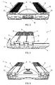
- the foot guard 1 has a sole plate 2. To reduce the dead weight, the sole plate 2 may have a recess 3. The sole plate 2 has an outsole 4 on its lower, in the applied state of the foot protector 1 facing away from the horn capsule side. The foot guard 1 has a toe guard 5 in its front area.
- the toe guard 5 comes, according to the Figures 10 - 11 to lie in the applied state of the foot protection 1 at or near a toe wall 12 of the horn capsule 13.
- a horn capsule wall 14 of the horn capsule 13 can further be divided into a horn capsule side wall 15 and a costume wall 16.
- the sole plate 2 in some areas on its, in the applied state of the foot protection 1 of the horn capsule side facing conical nubs, which improve the adhesion of the foot protection 1 and the horn capsule in the applied state of the foot protection.
- a so-called "spacer" 19 in different degrees of hardness can be inserted in the rear region of the sole plate 2.
- the flexibility of the foot protection 1 can be individually adapted to the needs of the animal.
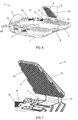
- the foot guard 1 has six matching elements 9. Each matching element 9 has at least one leg 10 and a base plate 11.
- the leg 10 is connected via a film hinge 23 with the base plate 11.
- the film hinge 23 is formed of several, introduced in the material weakening lines, and thus allows a bendable adjustment of the leg 10 relative to the horn capsule wall 14, and a simplified pressing and detachment of the horn capsule wall 14.
- the leg 10 and the base plate 11 via a Hinge be connected, whereby the leg would be rotatable about the hinge axis.
- each matching element 9 is connected to the sole plate 2.
- the base plate 11 is substantially radially, relative to the horn capsule wall 14 of the horn capsule 13 slidably formed, whereby the legs 10 are adjustable relative to the horn capsule wall 14.
- the base plate 11 is formed along a, substantially radially to the horn capsule wall 14 extending insertion direction ER in a Sohlenplattenaus principleung 17 of the sole plate 2 inserted and pulled out.
- FIG. 6 illustrates this in more detail, with one of the six matching elements 9 inserted and five shown away.
- FIG. 7 illustrates the inserted fitting element 9 in an enlarged view according to a section A from FIG. 6 ,
- Each leg 10 has holding means 8. These holding means 8 are integrated directly into a surface 20 of the leg 10. This surface 20 faces the horn capsule wall 14 in the applied state of the foot guard 1. Now, if fasteners 21 are attached to the horn capsule wall 14, so are in the applied state of the foot protection 1 holding means 8 and fasteners 21 opposite and can be connected together.
- the holding means 8 according to FIG. 7 a mushroom-like surface structure.
- a surface structure is commercially available and is sold, for example, by the company "3M TM” under the trademarks “Dual Lock TM” and “DuoTec TM”.
- the fastening means 21 have the same mushroom-like surface structure. This can be done by manual or by a tool, such as a plastic roller, assisted nesting of the holding means 8 and the fastening means 21 are made a positive connection. This compound has a particularly high shear strength and can be solved manually with relatively little effort substantially normal to the horn capsule wall 14 again.
- a similar structure namely a hook and loop-like surface structure, offers the company "VELCRO ® " under the brand name "Plastic Hooks”.
- the fastening means 21 may be attached exclusively on the horn capsule side wall 15 and not on the traditional wall 16 and the toe wall 12, which is beneficial for animal and user.
- the attachment means 21 may be additionally or exclusively attached to the toe wall 12, the dress wall 16, and / or any other part of the horn capsule wall 14.
- the attachment of the fastener 21 and the foot protector 1 can be adjusted according to the hoof shape of the animal, the application of the foot protector 1 or depending on the number and design of the matching elements 9.
- the mushroom-like surface structure of the holding means 8 and the fastening means 21 may also be formed as a microstructure, for example in the form of a "gecko tape". Furthermore, the surface structure of the holding means 8 and the fastening means 21 may be formed as hooks and loops or as "Metallic Velcro" made of spring steel.
- the mushroom-like surface structure of the holding means 8 is pressed manually or by means of a plastic roller into the mushroom-like surface structure of the fastening means 21, and thus made the shear-resistant connection.
- the foot protection 1 can be easily removed manually again from the hoof, the retaining means 8 are deducted from the fastening means 21.
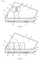
- FIG. 8 and FIG. 11 show according to the FIGS. 7 and 11 an adapter element 9 with holding means 6 according to a second embodiment of the invention.
- the holding means 6 and the fastening means 25 are formed as a detachable cable tie closure, wherein the fastening means 25 are formed as a cable tie head and the holding means as a cable tie tongue.
- the cable tie tongue is simply inserted and tightened manually when creating the foot protection 1 in the cable tie head.
- the cable tie head may be glued to the horn capsule wall 14 or integrated into a tissue tape glued to the horn capsule wall 14.
- Advantage of this design is the possibility of bias, which further reduce the margin between horn capsule wall 14 and foot protector 1 and may be important for animals with rotating Auffuß .
- FIG. 9 shows accordingly FIG. 7 an adapter element 9 with holding means 7 according to a third embodiment of the invention.
- the holding means 7 and the fastening means are designed as snap fastener.
- the push button, which forms the retaining means 7, while pressing the foot protection 1 is simply manually pressed into the counterpart of the push button, which is attachable to the horn capsule wall 14 as a fastening means.
- FIG. 10 and FIG. 13 show according to the FIGS. 7 and 11 an adapter element 9 with holding means 26 and fastening means 27, both of which are attached to the leg 10, wherein the holding means 26 and the fastening means 27 are integrated into a horn capsule wall 14 opposite surface 28 of the leg 10.
- the holding means 26 and fastening means 27 can be applied to the leg 10 in the form of a layer composite system.
- the holding means 26 may, for example, as a single-sided adhesive tape be executed, which has the form-fitting surface structure on the non-adhesive side.
- the adhesive tape is then glued to the leg 10 with the adhesive side and connected to the fastening means 27, which have a compatible surface structure on the side facing the retaining means 26.
- the fastening means 27 and the retaining means 26 can also be adhesively bonded to one another or even formed in one piece, since the hoof protection 1 in this case is furthermore detachably connectable and thus the technical effect of the invention is not impaired.
- the fastening means 27 have a horn structure facing the horn capsule 14, for example, a gecko structure, which is designed to form a shear-resistant and releasable connection with the horn capsule wall 14.
- the sole plate 2 consists of a particularly resistant, hard material with low density, for example aluminum, plastic, such as polyethylene (PE) or polypropylene (PP), particularly advantageously of a particularly resistant, hard material with particularly low density, such as carbon.
- a particularly resistant, hard material with low density for example aluminum, plastic, such as polyethylene (PE) or polypropylene (PP), particularly advantageously of a particularly resistant, hard material with particularly low density, such as carbon.
- PE polyethylene
- PP polypropylene
- the toe guard 5 can be used for security purposes, for example by means of an attached, light-reflecting passive retroreflective element, for information purposes, for example by means of an attached name of the animal or a code number, or for marketing purposes, for example by means of an attached emblem.
- the holding means 8 by applying an additional, substantially radially acting on the Hornkapselwand 14 force, in addition also be positively connected to the fastening means 21.
- the fastening means 21 for this purpose, for example, serve an additional screw.
Landscapes
- Life Sciences & Earth Sciences (AREA)
- Environmental Sciences (AREA)
- Zoology (AREA)
- Engineering & Computer Science (AREA)
- Wood Science & Technology (AREA)
- Animal Husbandry (AREA)
- Biodiversity & Conservation Biology (AREA)
- Footwear And Its Accessory, Manufacturing Method And Apparatuses (AREA)
- Catching Or Destruction (AREA)
- Helmets And Other Head Coverings (AREA)
- Professional, Industrial, Or Sporting Protective Garments (AREA)
Abstract
Verschlussverbundsystem (22) zum Befestigen eines Fußschutzes (1) an einer Hornkapsel (13) eines Tieres mit Befestigungsmitteln (21, 25, 27), die an einer Hornkapselwand (14) der Hornkapsel (13) anbringbar sind, und mit Haltemitteln (6-8, 26), die am Fußschutz (1) angebracht sind, wobei der Fußschutz (1) zumindest zwei Anpasselemente (9) mit jeweils zumindest einem Schenkel (10) aufweist, und wobei jeder Schenkel (10) im Wesentlichen radial, relativ zur Hornkapselwand (14) verschiebbar ausgebildet ist und eines der Haltemittel (6-8, 26) aufweist, die mit den Befestigungsmitteln (21, 25, 27) scherfest und lösbar verbindbar ausgebildet sind.A closure assembly (22) for securing a foot guard (1) to a horn capsule (13) of an animal having attachment means (21, 25, 27) attachable to a horn capsule wall (14) of the horn capsule (13) and retaining means (6). 8, 26) mounted on the foot guard (1), the foot guard (1) comprising at least two matching elements (9) each having at least one leg (10), and each leg (10) substantially radially relative to the horn capsule wall (14) is designed to be displaceable and one of the holding means (6-8, 26), which are shear-resistant and detachably connectable with the fastening means (21, 25, 27).
Description
Die Erfindung betrifft ein Verschlussverbundsystem zum Befestigen eines Fußschutzes an einer Hornkapsel eines Tieres mit Befestigungsmitteln, die an einer Hornkapselwand der Hornkapsel anbringbar sind, und mit Haltemitteln, die am Fußschutz angebracht sind.The invention relates to a closure composite system for securing a foot guard to a horn capsule of an animal with attachment means attachable to a horn capsule wall of the horn capsule, and to retaining means attached to the foot guard.
Einhufer, wie beispielsweise Pferd oder Esel, und Paarhufer, sogenannte Klauentiere wie beispielsweise Rind oder Schaf, weisen am untersten Teil der Gliedmaßen aus Hornkapseln gebildete Hufe oder Klauen auf. Wie Krallen und Fingernägel werden diese im Gebrauch abgenutzt und wachsen deshalb ständig nach. Da derartige Tiere heute üblicherweise als Haus- oder Nutztiere gehalten werden, können sie ihr natürliches Bewegungsverhalten häufig nicht mehr ausleben, wodurch Wachstum und Abrieb der Hufe und Klauen oft nicht mehr übereinstimmen. Um Erkrankungen der Hufe oder Klauen zu verhindern, müssen diese, je nach Beanspruchung, in regelmäßigen Abständen ausgeschnitten und bei starker Beanspruchung der Hornkapsel gegebenenfalls mit einem Fußschutz versehen werden.Steers, such as horse or donkey, and cloven-hoofed animals, so-called cloven-hoofed animals such as cattle or sheep, have hooves or claws formed on the lowest part of the limbs of horn capsules. Like claws and fingernails, these become worn in use and therefore constantly grow. Since such animals are now commonly kept as domestic or farm animals, they often can not live out their natural movement behavior, which growth and abrasion of the hooves and claws often no longer match. In order to prevent diseases of the hooves or claws, they must be cut out at regular intervals, depending on the load, and, if necessary, provided with foot protection when the horn capsule is heavily stressed.
Besonders bei Einhufern, die vermehrt auf hartem Untergrund, beispielweise auf geteerten Straßen, bewegt werden, ist das Anbringen eines Fußschutzes weit verbreitet. Bei Pferd, Esel und Maultier wird hierbei meist ein Hufeisen aus Metall genagelt, welche jedoch aufgrund mangelnder Stoßdämpfung und starrer Fixierung des beweglichen Tastorgans "Huf" erhebliche Nachteile für den Körper des Tieres mit sich bringen können. Ein über acht Wochen durch Aufnageln permanent aufgebrachter Hufschutz hat zudem den Nachteil, dass das, in der Beschlagsperiode um zwei bis vier Zentimeter nachwachsende Hufhorn sich nicht auf natürlichem Wege abreiben oder ausgeschnitten werden kann, sodass der an Umfang zunehmende Huf in seiner engen Ausgangsstellung fixiert bleibt. Eine falsche Fußstellung und damit einhergehende Schädigungen an Knochen, Sehnen und Bändern können die Folge sein.Especially with solipeds, which are increasingly moved on hard ground, for example on paved roads, the attachment of a foot protector is widespread. In horse, donkey and mule here usually a metal horseshoe is nailed, which, however, can bring considerable disadvantages for the body of the animal due to lack of shock absorption and rigid fixation of the movable tactile organ "hoof". A hoof protector permanently applied for more than eight weeks by nails also has the disadvantage that the hoof horn regrowing in the fitting period by two to four centimeters can not be naturally rubbed or cut out so that the hoof, which increases in circumference, remains fixed in its narrow initial position , A wrong foot position and associated damage to bones, tendons and ligaments can be the result.
Aufgrund der stoßdämpfenden Eigenschaften und der geringeren Verletzungsgefahr kamen in den letzten Jahren insbesondere bei Freizeitpferden vermehrt Kunststoffbeschläge zum Einsatz. Ein temporärer nagelloser Hufschutz, der die natürlichen Bewegungen des Hufs zulässt, wäre die ideale Lösung um die Gesundheit des Tieres zu erhalten. Lösungen in Form eines anschnallbaren oder anklebbaren Hufschuhs gibt es bereits auf dem Markt, mit dem Nachteil, dass diese bisher bis über das Fesselgelenk geführt werden mussten, was zu Scheuerstellen und, aufgrund der ungenauen Anpassbarkeit, immer wieder zum Verlust des Hufschutzes bei schnelleren Gangarten führte. Auch ist der Einsatz von Hufschuhen, die über die Fessel geführt werden, im Sportbereich nicht möglich, da diese das schnelle Drehen der Hufe auf dem Boden bei hoher Geschwindigkeit nicht zulassen.Due to the shock-absorbing properties and the lower risk of injury, plastic fittings have increasingly been used in recent years, especially in leisure horses. A temporary nailless hoof protection that allows for the natural movements of the hoof would be the ideal solution to maintain the health of the animal. Solutions in the form of an attachable or attachable hoofshoe are already on the market, with the disadvantage that they had previously been led to over the fetlock joint, resulting in chafing and, due to the inaccurate adaptability, again and again to the loss of Hufschutzes at faster gaits led. Also, the use of hoof boots, which are passed over the shackles, in the sports area is not possible because they do not allow the fast turning of the hooves on the ground at high speed.
Ein Hufschuh muss nach der Nutzung des Tieres durch den Reiter wieder entfernt werden, da das Pferdebein im Hufschuh schwitzt und sich aufreibt. Aus diesem Grund sollte ein Hufschuh ausschließlich auf die Befestigung an der Hornkapsel beschränkt und auf Wunsch jederzeit wieder abnehmbar sein. Im Gegensatz hierzu sollte es der Hufschuh zusätzlich ermöglichen, diesen bei Bedarf über mehrere Tage am Huf zu belassen ohne Gefahr zu laufen, dass dieser verloren geht oder, dass Scheuerstellen auftreten.A hoof boot must be removed after the use of the animal by the rider, as the horse's leg in the hoof shoe sweats and rubs. For this reason, a hoof shoe should be limited only to the attachment to the horn capsule and on request at any time be removable again. In contrast, the hoofshoe should additionally allow it to be left on the hoof for several days if necessary without running the risk of it being lost or causing chafing.
Das Dokument
Der Erfindung liegt die Aufgabe zugrunde einen temporären Fußschutz für unterschiedliche Hufe und Klauen zu ermöglichen, der eine zuverlässige Verbindung zwischen Fußschutz und Hornkapsel ermöglicht.The invention has for its object to provide a temporary foot protection for different hooves and claws, which allows a reliable connection between foot protection and horn capsule.
Erfindungsgemäß wird diese Aufgabenstellung dadurch gelöst, dass der Fußschutz zumindest zwei Anpasselemente mit jeweils zumindest einem Schenkel aufweist, wobei jeder Schenkel im Wesentlichen radial, relativ zur Hornkapselwand verschiebbar ausgebildet ist und eines der Haltemittel aufweist, die mit den Befestigungsmitteln scherfest und lösbar verbindbar ausgebildet sind.According to the invention, this object is achieved in that the foot protection has at least two matching elements, each having at least one leg, each leg is substantially radially, relative to the Hornkapselwand displaceable and one of the holding means which are formed scherfest and releasably connectable with the fastening means.
Hierdurch ist der Vorteil erhalten, dass der Fußschutz beim Anlegen schnell und einfach manuell an einen Huf oder eine Klaue angepasst werden kann, wobei sofort eine scherfeste und zuverlässige Verbindung zwischen Fußschutz und Hornkapsel ausgebildet wird. Hierbei ist die Verbindung zwischen Befestigungsmittel und Hornkapselwand stärker ausgebildet als die Verbindung zwischen Befestigungsmittel und Haltemittel. Nach Gebrauch des Fußschutzes kann dieser ebenso schnell und einfach manuell abgenommen werden, wobei die Befestigungsmittel an der Hornkapsel verbleiben können.As a result, the advantage is obtained that the foot protection can be adapted quickly and easily manually when putting on a hoof or a claw, which immediately a shear-resistant and reliable connection between foot protection and horn capsule is formed. Here, the connection between the fastening means and horn capsule wall is formed stronger than the connection between fastener and retaining means. After use of the foot protector, this can also be removed quickly and easily manually, wherein the attachment means can remain on the horn capsule.
Durch die zuverlässige Verbindung des erfindungsgemäßen Verschlussverbundsystems wird es erstmals möglich, einen temporären Fußschutz passgenau lediglich an der Hornkapselwand, vorzugsweise lediglich an einer Hornkapselseitenwand, des Hufs zu befestigen und wieder zu lösen. Die Anpasselemente pressen den Fußschutz auf die Hornkapsel, sodass vorteilhafterweise eine scherfeste und lösbare Verbindung ermöglicht wird. Besonders vorteilhaft ist hierbei, dass die Befestigungsmittel für die Hornkapselwand beschädigungsfrei an der Hornkapselwand befestigt werden. Es erfolgt somit kein Eindringen eines Nagels oder einer Schraube in die Hornkapselwand, die die Hornkapselwand beschädigen würde.Due to the reliable connection of the closure composite system according to the invention, it becomes possible for the first time to attach and release a temporary foot protection precisely only on the horn capsule wall, preferably only on a horn capsule side wall, of the hoof. The adapter elements press the foot guard on the horn capsule, so that advantageously a shear-resistant and detachable connection is made possible. It is particularly advantageous in this case that the fastening means for the horn capsule wall are attached without damage to the horn capsule wall. There is thus no penetration of a nail or a screw in the horn capsule wall, which would damage the horn capsule wall.
Vorteilhafterweise weisen die Haltemittel und/oder die Befestigungsmittel eine formschlüssige Oberflächenstruktur, vorzugsweise eine Oberflächenstruktur gemäß 3M™ Dual Lock™, 3M™ DuoTec™ oder VELCRO® Plastic Hooks, auf. Eine formschlüssige Verbindung zweier derartiger Oberflächen ist manuell lösbar verbindbar und weist gleichzeitig eine besonders hohe Scherfestigkeit auf.Advantageously, the holding means and / or the fastening means have a form-fitting surface structure, preferably a surface structure according to 3M ™ Dual Lock ™, 3M ™ DuoTec ™ or VELCRO ® Plastic Hooks. A positive connection of two such surfaces is manually releasably connectable and at the same time has a particularly high shear strength.
Besonders vorteilhaft sind die Haltemittel mit einer derartigen Oberflächenstruktur direkt in eine, den Befestigungsmitteln gegenüberliegende Oberfläche der Schenkel integriert ausgebildet. Hierdurch wird die Herstellung der Anpasselemente vereinfacht und die Haltemittel müssen nicht extra auf die Schenkel aufgebracht werden.Particularly advantageously, the holding means are formed with such a surface structure directly into a, the fastening means opposite surface of the legs integrated. As a result, the production of the matching elements is simplified and the holding means need not be applied extra to the legs.
Die Haltemittel und/oder die Befestigungsmittel können vorteilhafterweise auch aus einem Band, vorzugsweise einem einseitigen Klebeband, das die formschlüssige Oberflächenstruktur aufweist, ausgebildet sein. Hierdurch können die Haltemittel und/oder die Befestigungsmittel einfach und schnell ausgetauscht werden.The holding means and / or the fastening means may advantageously also be formed from a band, preferably a one-sided adhesive tape, which has the form-fitting surface structure. As a result, the holding means and / or the fastening means can be easily and quickly replaced.
Besonders vorteilhaft ist die Oberflächenstruktur als Mikrostruktur ausgebildet. Mikrostrukturen ermöglichen durch ihre besonderen Oberflächeneigenschaften neuartige Wirkungen und Effekte, beispielsweise besonders tragfähige Verbindungen oder selbstreinigende Oberflächen.Particularly advantageously, the surface structure is formed as a microstructure. Due to their special surface properties, microstructures enable novel effects and effects, for example particularly viable compounds or self-cleaning surfaces.
In einer weiteren vorteilhaften Ausgestaltung eines erfindungsgemäßen Verschlussverbundsystems sind die Haltemittel und die Befestigungsmittel als Einrastverbindung, vorzugsweise als Druckknopfverschluss oder als Druckverschlussschiene oder in Form einer Steck- oder Verschlussschnalle, ausgebildet. Diese Einrastverbindungen haben den Vorteil, dass die Verbindung vorgespannt werden kann, so dass auch bei Tieren mit schwierigem Auffußverhalten (Drehen des Hufs) der Fußschutz passgenau am Huf verbleibt.In a further advantageous embodiment of a closure composite system according to the invention, the holding means and the fastening means as Snap-in, preferably as a snap fastener or as a pressure-locking rail or in the form of a plug or closure buckle, formed. These snap-in connections have the advantage that the connection can be prestressed, so that even in animals with difficult footing behavior (turning of the hoof) the foot protection remains precisely fitting on the hoof.
In einer weiteren vorteilhaften Ausgestaltung eines erfindungsgemäßen Verschlussverbundsystems sind die Haltemittel und die Befestigungsmittel als lösbarer Kabelbinderverschluss ausgebildet, wobei vorzugsweise das Befestigungsmittel als Kabelbinderkopf und das Haltemittel als Kabelbinderzunge ausgebildet ist. Hierdurch ist der Vorteil gegeben, dass die Verbindung vorgespannt werden kann, so dass auch bei Tieren mit schwierigem Auffußverhalten (Drehen des Hufs) der Fußschutz passgenau am Huf verbleibt.In a further advantageous embodiment of a closure composite system according to the invention, the holding means and the fastening means are designed as a detachable cable tie closure, wherein preferably the fastening means is designed as a cable tie head and the holding means as a cable tie tongue. This provides the advantage that the connection can be prestressed, so that even in animals with difficult Auffußverhalten (turning the hoof), the foot protection remains accurately on the hoof.
In einer weiteren vorteilhaften Ausgestaltung eines erfindungsgemäßen Verschlussverbundsystems sind die Haltemittel und die Befestigungsmittel am Schenkel angebracht, wobei die Befestigungsmittel eine der Hornkapselwand zugewandte Saugnapfstruktur oder Mikrostruktur aufweisen, die zur Ausbildung einer scherfesten und lösbaren Verbindung mit der Hornkapselwand ausgebildet ist, und wobei die Verbindung zwischen Befestigungsmittel und Haltemittel stärker ist als die Verbindung zwischen Befestigungsmittel und Hornkapselwand. Hierdurch ist der Vorteil erhalten, dass kein Befestigungsmittel an der Hornkapsel verbleiben muss. Besonders vorteilhaft sind die Haltemittel und die Befestigungsmittel in eine der Hornkapselwand gegenüberliegende Oberfläche der Schenkel integriert ausgebildet.In a further advantageous embodiment of a closure composite system according to the invention, the holding means and the fastening means are mounted on the leg, wherein the fastening means comprise a Horn capsule wall facing the suction cup structure or microstructure, which is designed to form a shear-resistant and releasable connection with the horn capsule wall, and wherein the connection between fastening means and holding means is stronger than the connection between the fastener and horn capsule wall. This has the advantage that no attachment means must remain on the horn capsule. Particularly advantageously, the holding means and the fastening means are integrally formed in one of the horn capsule wall opposite surface of the legs.
Besonders vorteilhaft weisen die Anpasselemente jeweils eine Grundplatte auf, über welche Grundplatte sie mit dem Fußschutz verbunden sind, wobei die Grundplatte lösbar vom Fußschutz ausgebildet ist. Hierdurch können beispielsweise unterschiedliche Anpasselemente mit unterschiedlichen Haltemitteln, die mit dem jeweiligen Befestigungsmittel formschlüssig und/ oder andersartig, beispielsweise kraftschlüssig und/ oder stoffschlüssig, kompatibel sind, ausgetauscht werden. Weiters können kaputte oder zu reinigende Anpasselemente beziehungsweise Haltemittel einfach abgenommen und/oder ausgetauscht werden.Particularly advantageously, the matching elements each have a base plate, via which base plate they are connected to the foot protection, wherein the base plate is detachably formed by the foot protection. As a result, for example, different matching elements with different holding means which are compatible with the respective fastening means form-fitting and / or different, for example, non-positively and / or cohesively, are exchanged. Furthermore, broken or to be cleaned fitting elements or holding means can be easily removed and / or replaced.
Vorteilhaft bestehen die Anpasselemente und/oder der Fußschutz zumindest teilweise aus Metall, insbesondere aus rostfreiem Leichtbaustahl oder Aluminium, Gummi, Kunststoff, faserverstärktem Kunststoff oder aus Carbon, was dem Fußschutz die nötige Stabilität verleiht. Beispielsweise können durch eine Kunststoffsohle die stoßdämpfenden Eigenschaften verbessert werden, und Carbon weist eine besonders hohe Festigkeit bei verhältnismäßig geringer Dichte aufAdvantageously, the matching elements and / or the foot protection at least partially made of metal, in particular made of stainless lightweight steel or aluminum, rubber, plastic, fiber reinforced plastic or carbon, which gives the foot protection the necessary stability. For example, by a plastic sole, the shock-absorbing Properties are improved, and carbon has a particularly high strength at relatively low density
In einer vorteilhaften Weiterbildung eines erfindungsgemäßen Verschlussverbundsystems sind die Schenkel der Anpasselemente über ein Scharniergelenk oder ein Filmscharnier mit dem Fußschutz oder mit der Grundplatte der Anpasselemente biegbar verbunden. Hierdurch können die Anpasselemente und die Haltemittel an die Hornkapselwand angepasst werden.In an advantageous embodiment of a closure composite system according to the invention, the legs of the fitting elements are connected via a hinge joint or a film hinge with the foot protection or with the base plate of the matching elements bendable. As a result, the matching elements and the retaining means can be adapted to the horn capsule wall.
Im Folgenden wird das erfindungsgemäße Verschlussverbundsystem in nicht einschränkender Weise anhand von, in den Zeichnungen dargestellten beispielhaften Ausgestaltungen näher erläutert.
-
Figur 1 -
Figur 2Figur 1 -
Figur 3Figur 1 -
Figur 4Figur 1 -
Figur 5Figur 1 -
Figur 6Figur 1 -
Figur 7Figur 6 -
Figur 8 zeigtentsprechend Figur 7 einen Ausschnitt eines Fußschutzes gemäß einer zweiten Ausgestaltung der Erfindung. -
Figur 9entsprechend Figur 7 einen Ausschnitt eines Fußschutzes gemäß einer dritten Ausgestaltung der Erfindung. -
Figur 10entsprechend Figur 7 einen Ausschnitt eines Fußschutzes gemäß einer weiteren Ausgestaltung der Erfindung. -
Figur 11 -
Figur 12 -
Figur 13
-
FIG. 1 shows in a perspective view from above a foot protection according to a first embodiment of the invention. -
FIG. 2 shows in a perspective view from below the foot protection according toFIG. 1 , -
FIG. 3 shows in a view from behind the foot protection according toFIG. 1 , -
FIG. 4 shows in a side view according to the foot protectionFIG. 1 , -
FIG. 5 shows in a view from the front the foot protection according toFIG. 1 , -
FIG. 6 shows in a perspective view from above the foot protection according toFIG. 1 wherein five of the six matching elements are loosened and removed. -
FIG. 7 shows in enlarged perspective view a detail A fromFIG. 6 , -
FIG. 8 shows accordinglyFIG. 7 a section of a foot protector according to a second embodiment of the invention. -
FIG. 9 shows accordinglyFIG. 7 a section of a foot protector according to a third embodiment of the invention. -
FIG. 10 shows accordinglyFIG. 7 a section of a foot protector according to another embodiment of the invention. -
FIG. 11 schematically shows a closure system according to the invention according to the first embodiment of the invention. -
FIG. 12 schematically shows a closure system according to the invention according to the second embodiment of the invention. -
FIG. 13 schematically shows a closure system according to the invention according to the further embodiment of the invention.
Im Folgenden wird auf die
Der Fußschutz 1 weist eine Sohlenplatte 2 auf. Zur Verringerung des Eigengewichts kann die Sohlenplatte 2 eine Ausnehmung 3 aufweisen. Die Sohlenplatte 2 weist auf ihrer unteren, im angelegten Zustand des Fußschutzes 1 von der Hornkapsel abgewandten Seite eine Laufsohle 4 auf. Der Fußschutz 1 weist in seinem vorderen Bereich einen Zehenschutz 5 auf.The
Der Zehenschutz 5 kommt, gemäß den
In der vorliegenden ersten Ausgestaltung weist die Sohlenplatte 2 in einigen Bereichen auf ihrer, im angelegten Zustand des Fußschutzes 1 der Hornkapsel zugewandten Seite kegelförmige Noppen auf, welche im angelegten Zustand des Fußschutzes 1 die Haftung des Fußschutzes 1 and der Hornkapsel verbessern. Zur Anpassung der Flexibilität des Fußschutzes 1 im beweglichen Teil der Trachten des Hufs, ist im hinteren Bereich der Sohlenplatte 2 ein sogenannter "Spacer" 19 in verschiedenen Härtegraden einschiebbar. So kann die Flexibilität des Fußschutzes 1 individuell an die Bedürfnisse des Tieres angepasst werden.In the present first embodiment, the
Der Fußschutz 1 weist sechs Anpasselemente 9 auf. Jedes Anpasselement 9 weist zumindest einen Schenkel 10 und eine Grundplatte 11 auf. Der Schenkel 10 ist über ein Filmscharnier 23 mit der Grundplatte 11 verbunden. Das Filmscharnier 23 wird aus mehreren, im Material eingebrachten Schwächungslinien gebildet, und ermöglicht so ein biegbares Anpassen des Schenkels 10 relativ zur Hornkapselwand 14, sowie ein vereinfachtes Andrücken und Ablösen von der Hornkapselwand 14. Alternativ können der Schenkel 10 und die Grundplatte 11 auch über ein Scharniergelenk verbunden sein, wodurch der Schenkel um die Gelenkachse rotierbar wäre.The
Über die Grundplatte 11 ist jedes Anpasselement 9 mit der Sohlenplatte 2 verbunden. Dabei ist die Grundplatte 11 im Wesentlichen radial, relativ zur Hornkapselwand 14 der Hornkapsel 13 verschiebbar ausgebildet, wodurch die Schenkel 10 relativ zur Hornkapselwand 14 anpassbar sind. Hierbei ist die Grundplatte 11 entlang einer, im Wesentlichen radial zur Hornkapselwand 14 verlaufenden Einschubrichtung ER in eine Sohlenplattenausnehmung 17 der Sohlenplatte 2 einschiebbar und herausziehbar ausgebildet.
Alternativ könnten die Grundplatten 11 der Anpasselemente 9 auch einteilig mit der Sohlenplatte 2 ausgebildet sein. Die im Wesentlichen radiale Anpassbarkeit der Schenkel 10 relativ zur Hornkapselwand 14 würde dann beispielsweise über ein verlängertes, teilweise faltbares Filmscharnier oder Ähnliches realisiert sein.Alternatively, the
Die Grundplatte 11 und die Sohlenplatte 2 weisen an den sich berührenden Oberflächen jeweils komplementäre Oberflächenstrukturen 18, insbesondere Sägezahnstrukturen, auf, die einen Widerstand entgegen der Einschubrichtung ER ausbilden.The
Jeder Schenkel 10 weist Haltemittel 8 auf. Diese Haltemittel 8 sind direkt in eine Oberfläche 20 des Schenkels 10 integriert. Diese Oberfläche 20 ist im angelegten Zustand des Fußschutzes 1 der Hornkapselwand 14 zugewandt. Werden nun Befestigungsmittel 21 an der Hornkapselwand 14 angebracht, so liegen sich im angelegten Zustand des Fußschutzes 1 Haltemittel 8 und Befestigungsmittel 21 gegenüber und können miteinander verbunden werden.Each
Die Anpasselemente 9, welche an den Schenkeln 10 die Haltemittel 8 aufweisen, und die Befestigungsmittel 21, welche an der der Hornkapselwand 14 anbringbar sind, bilden somit das erfindungsgemäße Verschlussverbundsystem 22 zum Befestigen des Fußschutzes 1 an der Hornkapsel 13.The
Gemäß der ersten Ausgestaltung des Verschlussverbundsystems 22 weisen die Haltemittel 8 gemäß
Durch diese Verbindung ist es möglich die Befestigungsmittel 21 ausschließlich an der Hornkapselseitenwand 15 und nicht auch an der Trachtenwand 16 und der Zehenwand 12 anzubringen, was von Vorteil für Tier und Benutzer ist. Alternativ können die Befestigungsmittel 21 zusätzlich oder ausschließlich auch an der Zehenwand 12, der Trachtenwand 16, und/ oder an irgendeinem anderen Teil der Hornkapselwand 14 angebracht werden. Das Anbringen der Befestigungsmittel 21 beziehungsweise des Fußschutzes 1 kann so entsprechend der Hufform des Tieres, der Anwendung des Fußschutzes 1 oder Abhängig von Anzahl und Ausgestaltung der Anpasselemente 9 angepasst werden.By this connection, it is possible to attach the fastening means 21 exclusively on the horn
Das Befestigungsmittel 21 kann beispielsweise als einseitiges Klebeband ausgeführt sein, das die formschlüssige Oberflächenstruktur auf der, nicht den Klebstoff aufweisenden Seite aufweist. Das Klebeband wird dann mit der den Klebstoff aufweisenden Seite auf die Hornkapselwand 14 beziehungsweise die Hornkapselseitenwand 15 geklebt.The fastening means 21 can be embodied, for example, as a single-sided adhesive tape having the form-fitting surface structure on the non-adhesive side. The adhesive tape is then glued to the
Alternativ kann die pilzkopfartige Oberflächenstruktur der Haltemittel 8 und der Befestigungsmittel 21 auch als Mikrostruktur, beispielsweise in Form eines "Gecko-Tapes", ausgebildet sein. Weiters kann die Oberflächenstruktur der Haltemittel 8 und der Befestigungsmittel 21 als Haken und Schlaufen oder als "Metallic Velcro" aus Federstahl ausgebildet sein.Alternatively, the mushroom-like surface structure of the holding means 8 and the fastening means 21 may also be formed as a microstructure, for example in the form of a "gecko tape". Furthermore, the surface structure of the holding means 8 and the fastening means 21 may be formed as hooks and loops or as "Metallic Velcro" made of spring steel.
Ein typisches Verfahren zum Anbringen des Fußschutzes 1 mit dem erfindungsgemäßen Verschlussverbundsystem 22 kann folgendermaßen aussehen: Es wird ein Fußschutz 1 gewählt, der etwas größer als Huf des Tieres ist, beispielsweise mit einem Durchmesser von etwa 13 Zentimetern. Der Fußschutz 1 wird dann an die Hornkapsel 13 gehalten und gegebenenfalls auf die tatsächliche Größe des Hufs verkleinert. In einem nächsten Schritt wird der Huf mit Alkohol gereinigt, und das Befestigungsmittel 21 an der Hornkapselwand 14 angebracht, beispielsweise aufgeklebt. Dann wird der Fußschutz 1 an die Hornkapsel 13 gehalten und die Anpasselemente 9 werden manuell an die Hornkapselwand 14 geschoben.A typical method of attaching the
Sobald die Haltemittel 8 relativ zu den Befestigungsmitteln 21 ausreichend genau ausgerichtet sind, wird die pilzkopfartige Oberflächenstruktur der Haltemittel 8 manuell oder mittels eines Kunststoffrollers in die pilzkopfartige Oberflächenstruktur der Befestigungsmittel 21 gedrückt, und somit die scherfeste Verbindung hergestellt. Nach Gebrauch kann der Fußschutz 1 einfach wieder manuell vom Huf abgenommen werden, wobei die Haltemittel 8 von den Befestigungsmitteln 21 abgezogen werden.Once the holding means 8 are sufficiently accurately aligned relative to the attachment means 21, the mushroom-like surface structure of the holding means 8 is pressed manually or by means of a plastic roller into the mushroom-like surface structure of the fastening means 21, and thus made the shear-resistant connection. After use, the
Alternativ könnte die Kabelbinderzunge auch die, beispielsweise an der Hornkapselwand 14 angeklebten Befestigungsmittel 25 ausbilden. Die Anpasselemente 9 könnten einen, in den Schenkel 10 integrierten Kapelbinderkopf aufweisen, durch den die Kabelbinderzunge durchgezogen wird.Alternatively, the cable tie tongue could also form the, for example, glued to the
Die Befestigungsmittel 27 und die Haltemittel 26 können alternativ auch fest miteinander verklebt oder sogar einteilig ausgebildet sein, da der Hufschutz 1 in diesem Fall weiterhin lösbar verbindbar ausgebildet ist und so die technische Wirkung der Erfindung nicht beeinträchtigt ist. Alternativ weisen die Befestigungsmittel 27 eine der Hornkapselwand 14 zugewandte Mikrostruktur, beispielsweise eine Gecko-Struktur, auf, die zur Ausbildung einer scherfesten und lösbaren Verbindung mit der Hornkapselwand 14 ausgebildet ist.Alternatively, the fastening means 27 and the retaining means 26 can also be adhesively bonded to one another or even formed in one piece, since the
Vorteilhafterweise besteht die Sohlenplatte 2 aus einem besonders widerstandsfähigen, harten Material mit geringer Dichte, beispielsweise Aluminium, Kunststoff, wie beispielsweise Polyethylen (PE) oder Polypropylen (PP), besonders vorteilhafterweise aus einem besonders widerstandsfähigen, harten Material mit besonders geringer Dichte, beispielsweise Carbon.Advantageously, the
Vorteilhafterweise besteht die Laufsohle 4 aus einem widerstandsfähigen Material mit guten stoßdämpfenden Eigenschaften, beispielsweise Kunststoff, wie beispielsweise Ethylenvinylacetat (EVA), oder Gummi.Advantageously, the
Vorteilhafterweise kann der Zehenschutz 5 zu Sicherheitszwecken, beispielsweise mittels eines angebrachten, Licht reflektierenden passiven Rückstrahlelements, zu Informationszwecken, beispielsweise mittels eines angebrachten Namens des Tieres oder einer Kennzahl, oder zu Vermarktungszwecken, beispielsweise mittels eines angebrachten Emblems, genutzt werden.Advantageously, the
Vorteilhafterweise können die Haltemittel 8, durch Beaufschlagung einer zusätzlichen, im Wesentlichen radial auf die Hornkapselwand 14 einwirkenden Kraft, zusätzlich auch kraftschlüssig mit den Befestigungsmitteln 21 verbunden werden. Hierzu kann beispielsweise eine zusätzlich Verschraubung dienen.Advantageously, the holding means 8, by applying an additional, substantially radially acting on the
Bei allen Ausgestaltungen der Erfindung können die Befestigungsmittel für die Hornkapselwand beschädigungsfrei an der Hornkapselwand befestigt werden. Es erfolgt somit kein Eindringen eines Nagels oder einer Schraube in die Hornkapselwand, die die Hornkapselwand beschädigen würde. Dies verbessert die Haltbarkeit und Gesundheit der Tiere bezüglich ihrer Hufe oder Klauen.In all embodiments of the invention, the fastening means for the horn capsule wall can be attached without damage to the horn capsule wall. There is thus no penetration of a nail or a screw in the horn capsule wall, which would damage the horn capsule wall. This improves the durability and health of the animals with regard to their hooves or claws.
Claims (14)
dass der Fußschutz (1) zumindest zwei Anpasselemente (9) mit jeweils zumindest einem Schenkel (10) aufweist, wobei jeder Schenkel (10) im Wesentlichen radial, relativ zur Hornkapselwand (14) verschiebbar ausgebildet ist und eines der Haltemittel (6-8, 26) aufweist, die mit den Befestigungsmitteln (21, 25, 27) scherfest und lösbar verbindbar ausgebildet sind.A closure assembly (22) for securing a foot protector (1) to a horn capsule (13) of an animal having attachment means (21, 25, 27) attachable to a horn capsule wall (14) of the horn capsule (13), and retaining means (6). 8, 26) which are attached to the foot guard (1), characterized
in that the foot guard (1) has at least two matching elements (9) each with at least one leg (10), each leg (10) being designed to be substantially radially displaceable relative to the horn capsule wall (14) and one of the holding means (6-8, 26) which are shear-resistant and releasably connectable with the fastening means (21, 25, 27).
Priority Applications (7)
| Application Number | Priority Date | Filing Date | Title |
|---|---|---|---|
| ES16169307.2T ES2689220T3 (en) | 2016-05-12 | 2016-05-12 | Composite closure system for a foot protector |
| EP16169307.2A EP3243379B1 (en) | 2016-05-12 | 2016-05-12 | Closure composite system for a foot protector |
| DK16169307.2T DK3243379T3 (en) | 2016-05-12 | 2016-05-12 | Closing Connection System |
| CA3023951A CA3023951A1 (en) | 2016-05-12 | 2017-05-05 | Closure assembly system for a foot protection |
| PCT/EP2017/060760 WO2017194402A1 (en) | 2016-05-12 | 2017-05-05 | Fastening compound system for a foot protector |
| US16/300,632 US11291186B2 (en) | 2016-05-12 | 2017-05-05 | Fastening compound system for a foot protector |
| AU2017262618A AU2017262618B2 (en) | 2016-05-12 | 2017-05-05 | Fastening compound system for a foot protector |
Applications Claiming Priority (1)
| Application Number | Priority Date | Filing Date | Title |
|---|---|---|---|
| EP16169307.2A EP3243379B1 (en) | 2016-05-12 | 2016-05-12 | Closure composite system for a foot protector |
Publications (2)
| Publication Number | Publication Date |
|---|---|
| EP3243379A1 true EP3243379A1 (en) | 2017-11-15 |
| EP3243379B1 EP3243379B1 (en) | 2018-07-04 |
Family
ID=55970855
Family Applications (1)
| Application Number | Title | Priority Date | Filing Date |
|---|---|---|---|
| EP16169307.2A Active EP3243379B1 (en) | 2016-05-12 | 2016-05-12 | Closure composite system for a foot protector |
Country Status (7)
| Country | Link |
|---|---|
| US (1) | US11291186B2 (en) |
| EP (1) | EP3243379B1 (en) |
| AU (1) | AU2017262618B2 (en) |
| CA (1) | CA3023951A1 (en) |
| DK (1) | DK3243379T3 (en) |
| ES (1) | ES2689220T3 (en) |
| WO (1) | WO2017194402A1 (en) |
Cited By (1)
| Publication number | Priority date | Publication date | Assignee | Title |
|---|---|---|---|---|
| US20230122576A1 (en) * | 2021-10-20 | 2023-04-20 | Challen Ingraham | Sandwiched inverted horseshoe and methods of using same |
Families Citing this family (1)
| Publication number | Priority date | Publication date | Assignee | Title |
|---|---|---|---|---|
| CN114190294B (en) * | 2021-11-24 | 2022-09-23 | 西安电子科技大学 | Plasma pet comb that disinfects |
Citations (6)
| Publication number | Priority date | Publication date | Assignee | Title |
|---|---|---|---|---|
| US5692569A (en) * | 1995-10-17 | 1997-12-02 | Mustad, Incorporated | Horseshoe system |
| DE19742274A1 (en) | 1997-09-25 | 1998-03-05 | Stefan Dr Brosig | Method for detachably fixing interchangeable hoof protectors to hooves |
| DE19753120A1 (en) * | 1997-09-25 | 1998-06-04 | Stefan Dr Brosig | Method for detachably fixing hoof protector to hooves |
| DE19800695A1 (en) * | 1997-09-25 | 1998-06-18 | Stefan Dr Brosig | Placing shield on preferably horse's hoof |
| DE10346480A1 (en) * | 2003-06-05 | 2004-12-23 | Klein, Joachim | Hoof guard for use on hooved or clawed animals, has connection unit comprising of belt buckles mounted with detachable belts to maintain connection of hoof guard unit to animal hoof |
| WO2010039901A1 (en) * | 2008-10-02 | 2010-04-08 | Easycare, Inc. | Horse boot connected to glued-on liner |
Family Cites Families (30)
| Publication number | Priority date | Publication date | Assignee | Title |
|---|---|---|---|---|
| US600744A (en) * | 1898-03-15 | Nailless horseshoe | ||
| US172150A (en) * | 1876-01-11 | Improvement in horseshoes | ||
| US1403071A (en) * | 1918-06-14 | 1922-01-10 | George J Capewell | Horseshoe |
| US1351769A (en) * | 1918-12-26 | 1920-09-07 | Mary C Leinweber | Horseshoe |
| US1383508A (en) * | 1920-03-23 | 1921-07-05 | Witushen Mitro | Horseshoe |
| US1416658A (en) * | 1920-11-15 | 1922-05-16 | Michelsen Michael | Horseshoe |
| US1496511A (en) * | 1920-11-15 | 1924-06-03 | David W Allman | Horseshoe |
| US3163230A (en) * | 1962-01-25 | 1964-12-29 | Christensen Jens Juul | Horse shoe |
| US3494422A (en) * | 1967-01-16 | 1970-02-10 | Frank M Clark | Plastic horse shoe and method of applying to hoof |
| US4513824A (en) * | 1983-11-18 | 1985-04-30 | Ford Donald F | Flexible horseshoe |
| US4892150A (en) * | 1988-05-02 | 1990-01-09 | Thoman Owen E | Polymer horseshoe providing enhanced support |
| US5027904A (en) * | 1990-03-05 | 1991-07-02 | Miller Jack V | Racing plate horseshoe system with movable calks |
| US5172766A (en) * | 1991-08-12 | 1992-12-22 | Adkins Kirk E | Radially grooved horsehoes |
| US5842523A (en) * | 1995-05-31 | 1998-12-01 | Stuebbe; Peter | Ambulation-protection means for equine hoofs |
| DE10123205A1 (en) * | 2001-05-12 | 2002-11-28 | Binder Gottlieb Gmbh & Co | Production of section of touch-and-close fastener with support strip with integral hooks comprises adding mushroom-shaped layer of duroplast to top of hooks |
| US6571881B1 (en) * | 2002-04-05 | 2003-06-03 | Michael Nolan | Farrier's shoeing appliance |
| US20080264005A1 (en) * | 2004-12-13 | 2008-10-30 | Easycare, Inc. | Horse boot with elastic fastener |
| US8151545B1 (en) * | 2008-07-07 | 2012-04-10 | Easycare, Inc. | Horse boot with cupped sole |
| US8186447B2 (en) * | 2008-08-05 | 2012-05-29 | Robert Clark Osborne | Horse orthotic |
| US20120005995A1 (en) * | 2009-04-20 | 2012-01-12 | Leslie Emery | Hoof protection devices |
| US10206386B2 (en) * | 2013-10-04 | 2019-02-19 | Monty L. Ruetenik | Equine shoe |
| US20120261143A1 (en) * | 2011-02-11 | 2012-10-18 | Eponashoe, Inc. | Devices and methods for attaching a horseshoe to a hoof |
| US20140231101A1 (en) * | 2013-02-20 | 2014-08-21 | Easycare, Inc. | Glued-on horse boot with frog support |
| US20140231100A1 (en) * | 2013-02-20 | 2014-08-21 | Easycare, Inc. | Optionally glued-on or nailed-on horse shoe |
| US9538738B2 (en) * | 2013-03-13 | 2017-01-10 | Lyle Eugene Bergeleen | Horseshoe assembly and a method of mounting the same onto a horse hoof |
| AU2014202636A1 (en) * | 2014-05-14 | 2015-12-10 | Blue Pegasos Pty Ltd | Horseshoe |
| AU2015301139B2 (en) * | 2014-08-05 | 2018-11-01 | Milliken & Company | Two part floor covering |
| US20160044907A1 (en) * | 2014-08-18 | 2016-02-18 | Nigel Alexander Buchanan | Animal Overshoes |
| US10015956B2 (en) * | 2014-12-08 | 2018-07-10 | Broadline Farrier Solutions, Llc | Horseshoe with clips, blister member for a clip, and method of applying shoe to a horse's hoof |
| EP3103331B1 (en) | 2015-06-11 | 2019-01-16 | huf-atelier | Fitting for a hoof and method for fitting a hoof |
-
2016
- 2016-05-12 ES ES16169307.2T patent/ES2689220T3/en active Active
- 2016-05-12 EP EP16169307.2A patent/EP3243379B1/en active Active
- 2016-05-12 DK DK16169307.2T patent/DK3243379T3/en active
-
2017
- 2017-05-05 WO PCT/EP2017/060760 patent/WO2017194402A1/en active Application Filing
- 2017-05-05 US US16/300,632 patent/US11291186B2/en active Active
- 2017-05-05 CA CA3023951A patent/CA3023951A1/en active Pending
- 2017-05-05 AU AU2017262618A patent/AU2017262618B2/en active Active
Patent Citations (6)
| Publication number | Priority date | Publication date | Assignee | Title |
|---|---|---|---|---|
| US5692569A (en) * | 1995-10-17 | 1997-12-02 | Mustad, Incorporated | Horseshoe system |
| DE19742274A1 (en) | 1997-09-25 | 1998-03-05 | Stefan Dr Brosig | Method for detachably fixing interchangeable hoof protectors to hooves |
| DE19753120A1 (en) * | 1997-09-25 | 1998-06-04 | Stefan Dr Brosig | Method for detachably fixing hoof protector to hooves |
| DE19800695A1 (en) * | 1997-09-25 | 1998-06-18 | Stefan Dr Brosig | Placing shield on preferably horse's hoof |
| DE10346480A1 (en) * | 2003-06-05 | 2004-12-23 | Klein, Joachim | Hoof guard for use on hooved or clawed animals, has connection unit comprising of belt buckles mounted with detachable belts to maintain connection of hoof guard unit to animal hoof |
| WO2010039901A1 (en) * | 2008-10-02 | 2010-04-08 | Easycare, Inc. | Horse boot connected to glued-on liner |
Cited By (1)
| Publication number | Priority date | Publication date | Assignee | Title |
|---|---|---|---|---|
| US20230122576A1 (en) * | 2021-10-20 | 2023-04-20 | Challen Ingraham | Sandwiched inverted horseshoe and methods of using same |
Also Published As
| Publication number | Publication date |
|---|---|
| ES2689220T3 (en) | 2018-11-12 |
| DK3243379T3 (en) | 2018-09-24 |
| EP3243379B1 (en) | 2018-07-04 |
| US11291186B2 (en) | 2022-04-05 |
| WO2017194402A1 (en) | 2017-11-16 |
| AU2017262618B2 (en) | 2022-09-15 |
| CA3023951A1 (en) | 2017-11-16 |
| US20190208746A1 (en) | 2019-07-11 |
| AU2017262618A1 (en) | 2018-12-13 |
Similar Documents
| Publication | Publication Date | Title |
|---|---|---|
| EP1008295A2 (en) | Horseshoe | |
| EP3103331B1 (en) | Fitting for a hoof and method for fitting a hoof | |
| EP3243379B1 (en) | Closure composite system for a foot protector | |
| WO2012062304A2 (en) | Shoe for the hoofs of riding animals, in particular for horses, and connection part for and method of producing such a shoe | |
| CH624829A5 (en) | Method and device for shoeing a horse | |
| EP3254558A1 (en) | Fitting for a hoof of equidae | |
| DE102016011019A1 (en) | Length and width adjustable hoof shoe (shoe for horses) | |
| DE19630660C2 (en) | Hoof protection for horses and methods for applying such a hoof protection | |
| DE102005051707B4 (en) | Bale guards for the front hoof of a horse | |
| DE3423838A1 (en) | Shoe for hoofed animals, in particular for shoeing horses | |
| EP3451827B1 (en) | Horseshoe | |
| DE202007013692U1 (en) | Pferdehufschuh | |
| DE102013106161A1 (en) | Fixation element for attachment to a foot protection for animals and associated foot protection for animals | |
| DE19800695A1 (en) | Placing shield on preferably horse's hoof | |
| LU102801B1 (en) | Hoof protection for an equine hoof, method of manufacture and application | |
| DE19538093C2 (en) | Hoof protection | |
| DE202013103991U1 (en) | Hoof protection system for horses or similar ungulates | |
| DE19753120A1 (en) | Method for detachably fixing hoof protector to hooves | |
| DE3340095A1 (en) | Horseshoe with core | |
| EP1060666A2 (en) | Horseshoe | |
| DE19826099A1 (en) | Hoof cover esp. for horses | |
| EP0766511B1 (en) | Protection for horses' hooves | |
| DE102021112637A1 (en) | Hoof protection for an equine hoof, method of manufacture and application | |
| WO2023066429A1 (en) | Method for producing a device for the protection of a body part, and device | |
| DE102012109021A1 (en) | Tongue for shoes, has longitudinal extending bracing that is integrally connected with transverse bracings, such that transverse bracing is made narrower than tongue extending recesses |
Legal Events
| Date | Code | Title | Description |
|---|---|---|---|
| STAA | Information on the status of an ep patent application or granted ep patent |
Free format text: STATUS: EXAMINATION IS IN PROGRESS |
|
| PUAI | Public reference made under article 153(3) epc to a published international application that has entered the european phase |
Free format text: ORIGINAL CODE: 0009012 |
|
| 17P | Request for examination filed |
Effective date: 20170327 |
|
| AK | Designated contracting states |
Kind code of ref document: A1 Designated state(s): AL AT BE BG CH CY CZ DE DK EE ES FI FR GB GR HR HU IE IS IT LI LT LU LV MC MK MT NL NO PL PT RO RS SE SI SK SM TR |
|
| AX | Request for extension of the european patent |
Extension state: BA ME |
|
| GRAP | Despatch of communication of intention to grant a patent |
Free format text: ORIGINAL CODE: EPIDOSNIGR1 |
|
| STAA | Information on the status of an ep patent application or granted ep patent |
Free format text: STATUS: GRANT OF PATENT IS INTENDED |
|
| INTG | Intention to grant announced |
Effective date: 20171208 |
|
| GRAS | Grant fee paid |
Free format text: ORIGINAL CODE: EPIDOSNIGR3 |
|
| GRAA | (expected) grant |
Free format text: ORIGINAL CODE: 0009210 |
|
| STAA | Information on the status of an ep patent application or granted ep patent |
Free format text: STATUS: THE PATENT HAS BEEN GRANTED |
|
| AK | Designated contracting states |
Kind code of ref document: B1 Designated state(s): AL AT BE BG CH CY CZ DE DK EE ES FI FR GB GR HR HU IE IS IT LI LT LU LV MC MK MT NL NO PL PT RO RS SE SI SK SM TR |
|
| REG | Reference to a national code |
Ref country code: GB Ref legal event code: FG4D Free format text: NOT ENGLISH |
|
| REG | Reference to a national code |
Ref country code: CH Ref legal event code: EP |
|
| REG | Reference to a national code |
Ref country code: AT Ref legal event code: REF Ref document number: 1013510 Country of ref document: AT Kind code of ref document: T Effective date: 20180715 |
|
| REG | Reference to a national code |
Ref country code: IE Ref legal event code: FG4D Free format text: LANGUAGE OF EP DOCUMENT: GERMAN |
|
| REG | Reference to a national code |
Ref country code: DE Ref legal event code: R096 Ref document number: 502016001385 Country of ref document: DE |
|
| REG | Reference to a national code |
Ref country code: CH Ref legal event code: NV Representative=s name: SCHMAUDER AND PARTNER AG PATENT- UND MARKENANW, CH |
|
| REG | Reference to a national code |
Ref country code: DK Ref legal event code: T3 Effective date: 20180919 |
|
| REG | Reference to a national code |
Ref country code: SE Ref legal event code: TRGR |
|
| REG | Reference to a national code |
Ref country code: NL Ref legal event code: FP |
|
| REG | Reference to a national code |
Ref country code: ES Ref legal event code: FG2A Ref document number: 2689220 Country of ref document: ES Kind code of ref document: T3 Effective date: 20181112 |
|
| REG | Reference to a national code |
Ref country code: LT Ref legal event code: MG4D |
|
| PG25 | Lapsed in a contracting state [announced via postgrant information from national office to epo] |
Ref country code: CZ Free format text: LAPSE BECAUSE OF FAILURE TO SUBMIT A TRANSLATION OF THE DESCRIPTION OR TO PAY THE FEE WITHIN THE PRESCRIBED TIME-LIMIT Effective date: 20180704 Ref country code: RS Free format text: LAPSE BECAUSE OF FAILURE TO SUBMIT A TRANSLATION OF THE DESCRIPTION OR TO PAY THE FEE WITHIN THE PRESCRIBED TIME-LIMIT Effective date: 20180704 Ref country code: IS Free format text: LAPSE BECAUSE OF FAILURE TO SUBMIT A TRANSLATION OF THE DESCRIPTION OR TO PAY THE FEE WITHIN THE PRESCRIBED TIME-LIMIT Effective date: 20181104 Ref country code: NO Free format text: LAPSE BECAUSE OF FAILURE TO SUBMIT A TRANSLATION OF THE DESCRIPTION OR TO PAY THE FEE WITHIN THE PRESCRIBED TIME-LIMIT Effective date: 20181004 Ref country code: GR Free format text: LAPSE BECAUSE OF FAILURE TO SUBMIT A TRANSLATION OF THE DESCRIPTION OR TO PAY THE FEE WITHIN THE PRESCRIBED TIME-LIMIT Effective date: 20181005 Ref country code: BG Free format text: LAPSE BECAUSE OF FAILURE TO SUBMIT A TRANSLATION OF THE DESCRIPTION OR TO PAY THE FEE WITHIN THE PRESCRIBED TIME-LIMIT Effective date: 20181004 Ref country code: PL Free format text: LAPSE BECAUSE OF FAILURE TO SUBMIT A TRANSLATION OF THE DESCRIPTION OR TO PAY THE FEE WITHIN THE PRESCRIBED TIME-LIMIT Effective date: 20180704 Ref country code: LT Free format text: LAPSE BECAUSE OF FAILURE TO SUBMIT A TRANSLATION OF THE DESCRIPTION OR TO PAY THE FEE WITHIN THE PRESCRIBED TIME-LIMIT Effective date: 20180704 |
|
| PG25 | Lapsed in a contracting state [announced via postgrant information from national office to epo] |
Ref country code: HR Free format text: LAPSE BECAUSE OF FAILURE TO SUBMIT A TRANSLATION OF THE DESCRIPTION OR TO PAY THE FEE WITHIN THE PRESCRIBED TIME-LIMIT Effective date: 20180704 Ref country code: LV Free format text: LAPSE BECAUSE OF FAILURE TO SUBMIT A TRANSLATION OF THE DESCRIPTION OR TO PAY THE FEE WITHIN THE PRESCRIBED TIME-LIMIT Effective date: 20180704 Ref country code: AL Free format text: LAPSE BECAUSE OF FAILURE TO SUBMIT A TRANSLATION OF THE DESCRIPTION OR TO PAY THE FEE WITHIN THE PRESCRIBED TIME-LIMIT Effective date: 20180704 |
|
| REG | Reference to a national code |
Ref country code: DE Ref legal event code: R097 Ref document number: 502016001385 Country of ref document: DE |
|
| PG25 | Lapsed in a contracting state [announced via postgrant information from national office to epo] |
Ref country code: RO Free format text: LAPSE BECAUSE OF FAILURE TO SUBMIT A TRANSLATION OF THE DESCRIPTION OR TO PAY THE FEE WITHIN THE PRESCRIBED TIME-LIMIT Effective date: 20180704 Ref country code: EE Free format text: LAPSE BECAUSE OF FAILURE TO SUBMIT A TRANSLATION OF THE DESCRIPTION OR TO PAY THE FEE WITHIN THE PRESCRIBED TIME-LIMIT Effective date: 20180704 |
|
| PLBE | No opposition filed within time limit |
Free format text: ORIGINAL CODE: 0009261 |
|
| STAA | Information on the status of an ep patent application or granted ep patent |
Free format text: STATUS: NO OPPOSITION FILED WITHIN TIME LIMIT |
|
| PG25 | Lapsed in a contracting state [announced via postgrant information from national office to epo] |
Ref country code: SM Free format text: LAPSE BECAUSE OF FAILURE TO SUBMIT A TRANSLATION OF THE DESCRIPTION OR TO PAY THE FEE WITHIN THE PRESCRIBED TIME-LIMIT Effective date: 20180704 Ref country code: SK Free format text: LAPSE BECAUSE OF FAILURE TO SUBMIT A TRANSLATION OF THE DESCRIPTION OR TO PAY THE FEE WITHIN THE PRESCRIBED TIME-LIMIT Effective date: 20180704 |
|
| 26N | No opposition filed |
Effective date: 20190405 |
|
| PG25 | Lapsed in a contracting state [announced via postgrant information from national office to epo] |
Ref country code: SI Free format text: LAPSE BECAUSE OF FAILURE TO SUBMIT A TRANSLATION OF THE DESCRIPTION OR TO PAY THE FEE WITHIN THE PRESCRIBED TIME-LIMIT Effective date: 20180704 |
|
| PG25 | Lapsed in a contracting state [announced via postgrant information from national office to epo] |
Ref country code: MC Free format text: LAPSE BECAUSE OF FAILURE TO SUBMIT A TRANSLATION OF THE DESCRIPTION OR TO PAY THE FEE WITHIN THE PRESCRIBED TIME-LIMIT Effective date: 20180704 |
|
| PG25 | Lapsed in a contracting state [announced via postgrant information from national office to epo] |
Ref country code: LU Free format text: LAPSE BECAUSE OF NON-PAYMENT OF DUE FEES Effective date: 20190512 |
|
| PG25 | Lapsed in a contracting state [announced via postgrant information from national office to epo] |
Ref country code: TR Free format text: LAPSE BECAUSE OF FAILURE TO SUBMIT A TRANSLATION OF THE DESCRIPTION OR TO PAY THE FEE WITHIN THE PRESCRIBED TIME-LIMIT Effective date: 20180704 |
|
| PG25 | Lapsed in a contracting state [announced via postgrant information from national office to epo] |
Ref country code: IE Free format text: LAPSE BECAUSE OF NON-PAYMENT OF DUE FEES Effective date: 20190512 |
|
| PG25 | Lapsed in a contracting state [announced via postgrant information from national office to epo] |
Ref country code: PT Free format text: LAPSE BECAUSE OF FAILURE TO SUBMIT A TRANSLATION OF THE DESCRIPTION OR TO PAY THE FEE WITHIN THE PRESCRIBED TIME-LIMIT Effective date: 20181104 |
|
| PG25 | Lapsed in a contracting state [announced via postgrant information from national office to epo] |
Ref country code: CY Free format text: LAPSE BECAUSE OF FAILURE TO SUBMIT A TRANSLATION OF THE DESCRIPTION OR TO PAY THE FEE WITHIN THE PRESCRIBED TIME-LIMIT Effective date: 20180704 |
|
| PG25 | Lapsed in a contracting state [announced via postgrant information from national office to epo] |
Ref country code: HU Free format text: LAPSE BECAUSE OF FAILURE TO SUBMIT A TRANSLATION OF THE DESCRIPTION OR TO PAY THE FEE WITHIN THE PRESCRIBED TIME-LIMIT; INVALID AB INITIO Effective date: 20160512 Ref country code: MT Free format text: LAPSE BECAUSE OF FAILURE TO SUBMIT A TRANSLATION OF THE DESCRIPTION OR TO PAY THE FEE WITHIN THE PRESCRIBED TIME-LIMIT Effective date: 20180704 |
|
| PG25 | Lapsed in a contracting state [announced via postgrant information from national office to epo] |
Ref country code: MK Free format text: LAPSE BECAUSE OF FAILURE TO SUBMIT A TRANSLATION OF THE DESCRIPTION OR TO PAY THE FEE WITHIN THE PRESCRIBED TIME-LIMIT Effective date: 20180704 |
|
| PGFP | Annual fee paid to national office [announced via postgrant information from national office to epo] |
Ref country code: NL Payment date: 20230530 Year of fee payment: 8 Ref country code: IT Payment date: 20230531 Year of fee payment: 8 Ref country code: FR Payment date: 20230531 Year of fee payment: 8 Ref country code: ES Payment date: 20230621 Year of fee payment: 8 Ref country code: DK Payment date: 20230530 Year of fee payment: 8 Ref country code: DE Payment date: 20230620 Year of fee payment: 8 Ref country code: CH Payment date: 20230628 Year of fee payment: 8 |
|
| PGFP | Annual fee paid to national office [announced via postgrant information from national office to epo] |
Ref country code: SE Payment date: 20230530 Year of fee payment: 8 Ref country code: FI Payment date: 20230530 Year of fee payment: 8 Ref country code: AT Payment date: 20230530 Year of fee payment: 8 |
|
| PGFP | Annual fee paid to national office [announced via postgrant information from national office to epo] |
Ref country code: BE Payment date: 20230530 Year of fee payment: 8 |
|
| PGFP | Annual fee paid to national office [announced via postgrant information from national office to epo] |
Ref country code: GB Payment date: 20230622 Year of fee payment: 8 |