EP3243250B1 - Method for the severance of an electrical power cable, or of a strand section, device therefor, as well as cutting device - Google Patents
Method for the severance of an electrical power cable, or of a strand section, device therefor, as well as cutting device Download PDFInfo
- Publication number
- EP3243250B1 EP3243250B1 EP16704284.5A EP16704284A EP3243250B1 EP 3243250 B1 EP3243250 B1 EP 3243250B1 EP 16704284 A EP16704284 A EP 16704284A EP 3243250 B1 EP3243250 B1 EP 3243250B1
- Authority
- EP
- European Patent Office
- Prior art keywords
- cutting
- frame section
- cutting blade
- sensor
- evaluation
- Prior art date
- Legal status (The legal status is an assumption and is not a legal conclusion. Google has not performed a legal analysis and makes no representation as to the accuracy of the status listed.)
- Active
Links
Images









Classifications
-
- H—ELECTRICITY
- H02—GENERATION; CONVERSION OR DISTRIBUTION OF ELECTRIC POWER
- H02G—INSTALLATION OF ELECTRIC CABLES OR LINES, OR OF COMBINED OPTICAL AND ELECTRIC CABLES OR LINES
- H02G1/00—Methods or apparatus specially adapted for installing, maintaining, repairing or dismantling electric cables or lines
- H02G1/005—Methods or apparatus specially adapted for installing, maintaining, repairing or dismantling electric cables or lines for cutting cables or wires, or splicing
-
- B—PERFORMING OPERATIONS; TRANSPORTING
- B23—MACHINE TOOLS; METAL-WORKING NOT OTHERWISE PROVIDED FOR
- B23D—PLANING; SLOTTING; SHEARING; BROACHING; SAWING; FILING; SCRAPING; LIKE OPERATIONS FOR WORKING METAL BY REMOVING MATERIAL, NOT OTHERWISE PROVIDED FOR
- B23D29/00—Hand-held metal-shearing or metal-cutting devices
- B23D29/002—Hand-held metal-shearing or metal-cutting devices for cutting wire or the like
-
- B—PERFORMING OPERATIONS; TRANSPORTING
- B23—MACHINE TOOLS; METAL-WORKING NOT OTHERWISE PROVIDED FOR
- B23D—PLANING; SLOTTING; SHEARING; BROACHING; SAWING; FILING; SCRAPING; LIKE OPERATIONS FOR WORKING METAL BY REMOVING MATERIAL, NOT OTHERWISE PROVIDED FOR
- B23D29/00—Hand-held metal-shearing or metal-cutting devices
- B23D29/02—Hand-operated metal-shearing devices
- B23D29/023—Hand-operated metal-shearing devices for cutting wires
-
- G—PHYSICS
- G01—MEASURING; TESTING
- G01R—MEASURING ELECTRIC VARIABLES; MEASURING MAGNETIC VARIABLES
- G01R21/00—Arrangements for measuring electric power or power factor
- G01R21/006—Measuring power factor
-
- H—ELECTRICITY
- H01—ELECTRIC ELEMENTS
- H01B—CABLES; CONDUCTORS; INSULATORS; SELECTION OF MATERIALS FOR THEIR CONDUCTIVE, INSULATING OR DIELECTRIC PROPERTIES
- H01B9/00—Power cables
- H01B9/02—Power cables with screens or conductive layers, e.g. for avoiding large potential gradients
-
- H—ELECTRICITY
- H02—GENERATION; CONVERSION OR DISTRIBUTION OF ELECTRIC POWER
- H02G—INSTALLATION OF ELECTRIC CABLES OR LINES, OR OF COMBINED OPTICAL AND ELECTRIC CABLES OR LINES
- H02G9/00—Installations of electric cables or lines in or on the ground or water
- H02G9/02—Installations of electric cables or lines in or on the ground or water laid directly in or on the ground, river-bed or sea-bottom; Coverings therefor, e.g. tile
Definitions
- US 6 552 522 B1 does disclose a pair of pliers which has also cutting edges.
- the pliers have piercing probes for using the pliers as a circuit-testing probe.
- the force, at which a testing probe is biased against a wire to be cut, can be determined by the degree of manual force applied to the handles of the pliers.
- the invention is concerned with the problem to provide a cutting device enabling an advantageous cutting.
- the cutting device provided for is capable of being opened with regard to the cutting device aperture, in particular for the severance of longer or installed strand sections (such as, for example, power cables in the form of buried cables) for surrounding the strand section during the severance process.
- strand sections such as, for example, power cables in the form of buried cables
- the cutting device aperture is so large such that strand sections of different diameters or cross-section geometries, respectively, can be severed with the same cutting device.
- Strand sections comprising a cross-section which is small as compared to the cutting device aperture, can result in an unfavorable orientation of the strand section within the cutting device aperture in the course of the severance process, thus also to a tilting of the strand section from a vertical to the aperture surface. This can lead to a cut, which is inexact and which might run at an incline.
- a strand section may be surrounded with an adapter, which is matched to the aperture dimension of the cutting device aperture and on then introducing the adapter with the strand section into the cutting device aperture.
- a correct, predetermined orientation of the strand section to be severed can be attained within the cutting device aperture by the adapter.
- the adapter for this can be present in the form of a pipe section, comprising an inner cross-section, which is matched to the outer cross-section of the strand section, and comprising an outer cross-section, which is matched to the cutting device aperture.
- the adapter may be destroyed in the course of the severance of the strand section, because the adapter is also severed. Accordingly, the adapter can only be used once.
- the adapter can also include two adapters, which are connected with one another via severable webs or the like.
- the webs can be replaceable plug-in components or the like.
- An entire measuring arrangement of the device thus in particular the evaluation controller is furthermore provided with its own power supply.
- the electrical supply of the measuring device can also take place via the device supply.
- the evaluation controller can also be provided directly at the device, whereby a compact device is specified, which includes the load control in the course of the severance process.
- the device has a cutting head, which is formed so as to encompass the cable completely.
- the cutting head has a cutting head aperture, which, for the severance of the power cable or a strand section, respectively, is penetrated by it.
- the cutting head can be opened so as to place it around the cable to be severed.
- the cutting head has a pivotable frame section, which, if applicable, supports the stationary cutting blade.
- the pivotable frame section Prior to executing the severance process, the pivotable frame section must be fixed and locked to a stationary frame section, which, if applicable, guides the movable cutting blade.
- the evaluation controller can be arranged on the cutting head, thus for example at the pivotable frame part of the cutting head.
- the evaluation controller can also be arranged laterally displaced from a traverse path of the movable cutting blade.
- the evaluation and/or transmission controller is thus arranged in a plane, which is offset to a cutting plane between the movable and the stationary cutting blade.
- the cutting blade In the closed position, the cutting blade can be locked by a locking bolt. Provision may be made for a locking bolt, which can be displaced transverse to the direction of displacement of the movable cutting blade and which is held at a stationary frame section of the device and which, in the locked position, penetrates a corresponding borehole of the pivotable frame section of the device.
- the pivotable frame section of the device may be held on the stationary frame section so as to be capable of being pivotably moved about a pivot axis, which is oriented parallel to the bolt axis.
- the position of the locking bolt can be registered and evaluated in the evaluation controller. In the event that a correct locked position of the bolt is registered, for example, a severance process can thus be triggered. If applicable, the correct locked position also ensures the correct positioning of the measuring probe, so that a correct load test of the cable can also be executed in the event of a correct locking.
- the movable cutting blade has a passive sensor, which is displaced accordingly with the movable cutting blade in the course of the severance of the cable.
- the passive sensor can be a magnet and/or RFID unit or reflector unit.
- the passive sensor is provided on the movable cutting blade, at a position which does not penetrate the cable in the course of the severance.
- the active sensor In the event of registering the passive sensor on the cutting blade side, the active sensor generates and end position signal, which represents the finalization of the severance process.
- the generated signal can be represented as optical and/or acoustic signal or also as electrical signal for relocating the movable cutting blade into the initial position.
- Cutting devices of the type in question have a cutting device aperture in the region of the cutting head, which is suitable to penetrate items to be cut comprising different cross-sectional dimensions.
- the problem of an unsatisfactory cut often results in particular in the case of items to be cut, which have cross-sections, which are relatively small as compared to the aperture dimension, for example cross-sectional dimensions, which correspond to half or less of the maximum aperture dimension of the device aperture.
- the item to be cut is displaced essentially into the central region with respect to the aperture cross-section of the cutting device. In this position, which is oriented centrally, if applicable, the item to be cut is severed.
- Cross-sections which are at least approximately always the same, result from this. It can also be ensured through this that the item to be cut is severed completely due to overlapping of the cutting blades relative to one another.
- the positioning part in total can also be moved in a guided manner in a direction of displacement of the movable cutting blade.
- the movement of the positioning part can hereby result directly from the movement of the cutting blade, for example by dragging the item to be cut across the movable cutting blade, into a stop position of the positioning part.
- the stop position the item to be cut is in an orientation within the cutting device aperture. In this orientation, the actual cutting process takes place hereafter.
- a positioning part which can be moved in a direction, which corresponds to the movable cutting blade, provision can be made for guidance.
- They can include one or a plurality of elongated holes with running guide pins mounted therein.
- the elongated holes may extend in the direction of displacement of the movable cutting blade and may be provided at the positioning part.
- a movable positioning part can be displaced from an initial position, which is initially unloaded by the item to be cut, counter to a spring force, which effects a resetting.
- a spring force may be chosen to be so low that the movable cutting blade does not or does not significantly cut into the cable before the cable has reached a stop-limiting end position in the region of the positioning part or in the region of the stationary cutting blade, respectively.
- the positioning part can also be deflected counter to the direction of displacement of the movable cutting blade in the course of a cutting operation.
- the positioning part can furthermore also be displaced essentially crosswise to the direction of displacement of the movable cutting blade in the course of the forward displacement of the movable cutting blade.
- An adapter can be provided for enclosing an item to be cut in the form of a strand.
- Such an adapter can be used to adapt the strand-shaped item to be cut to an aperture cross-section of a cutting device, whereby an item to be cut comprising a comparatively small cross-sectional dimension can also be cut correctly in a cutting device comprising an aperture, which is large as compared thereto.
- the adapter For an cost-efficient adapter from a manufacturing standpoint, it is proposed for the adapter to be formed from a material that can be cut easily, such as foam, plastic, such as, in particular, soft plastic, or balsa wood, and for the adapter to be formed in two parts, wherein the parts can be connected with one another for purposes of pivoting.
- a material that can be cut easily such as foam, plastic, such as, in particular, soft plastic, or balsa wood
- the material selection of the adapter provides a cost-efficient production thereof. At the same time, the adapter can be severed easily by a cutting device due to the material selection.
- the material can also be an elastically resilient foam.
- the two-part design makes it possible to place such an adapter around an item to be cut, which, due to the length and/or installation type thereof, does not allow a one-part adapter to be slid on.
- the adapter can have a substantially circular layout with respect to a view, in which a geometric axis of an aperture of the adapter for the passage of the item to be cut is in the form of a point.
- the layout may be adapted to an aperture cross-section of a cutting device and can accordingly also be formed essentially elongated and/or approximately rectangular.
- a device 1 in the form of a hydraulic cutting device 2 for the severance of a strand-shaped item to be cut 3, in particular a strand section 4, and, as illustrated, a power cable 5, is illustrated and described with reference to FIG. 1 .
- the disclosure is also relevant for a strand-shaped item to be cut or a strand section, respectively, insofar as a voltage admission, as might possibly be present in the case of the electrical power cable, is not important.
- the electrical power cable 5 is a high voltage power cable.
- FIG. 1 schematically illustrates a situation, in which the power cable 5, which is to be severed, is installed as item to be cut 3 in an exposed trench 6.
- the operating position shown in FIG. 2 can be fixed, for example, in a hold-open position.
- the support regions of the positioning parts 37, 38 are connected to one another in a gear-driven manner, in particular by of gear wheels 44, 45. Accordingly, the pivot displacement of a positioning part 37, 38 leads via the gear wheels 44, 45 to the counter-directional orientation, which draws the same angle to the central axis, of the other positioning part 38, 37.
- the orientation of the positioning parts 37, 38, which run in a V-shaped manner and which can thus be pre-adjusted by the user, can be fixed via a screw 46. Provision can also be made at the journal 43 for markings in the form of numbers, by a pre-adjustment can be made so as to be matched to the outer diameter dimensions of the item to be cut 3.
- An item to be cut 3, which is seated within the cutting device aperture 27, is also pushed via the movable cutting blade 11 along the facing outer edges of the positioning part 37 to the center of the cutting device aperture 27, wherein the positioning part 37 is able to give way in the direction of displacement r in the course of the cutting process.
- the adapter 52 has an outer cross-sectional contour, which is matched to the cross-sectional contour of the cutting device aperture 27.
- the cross-sectional inner contour of the adapter 52 is matched or, due to the material selection, can be matched to the outer cross-section of the item to be cut 3 (here of a power cable 5; see FIGS. 16-18 ).
- the adapter 52 is severed in the course of the cutting process.
- the spike 62 of the measuring probe 26 can be embodied as the cutting blade 16 having an insulative sheath (not shown), like that of insulative sheath 64, surrounding the portions of which are to remain electrically isolated from the cutting device 2 or device 1, with the cutting edge 18 remaining exposed and forming the spike tip, like that of spike tip 65.
- the insulative sheath partially surrounding the cutting blade 16 may be formed of ceramic.
- the sensors 24, 32, 33 are in communication with the evaluation and/or transmission controller 29. Such communication may be done via wires or wirelessly.
- the severance of an outer layer, in particular of the cable sheath 34 has the effect or is executed to the extent, respectively, that the cutting blade 11is in contact with the wires 60 of the screening layer 35.
- the wires 60 are arranged below the outer layer, thus below the cable sheath 34 or on the inside of the cable sheath 34, respectively.
- a cut is made into the power cable 5 by the measuring probe 26, namely to the extent that the wires 60 are cut through and that the measuring probe 26 contacts the sheath 36.
- a resistance measurement is then executed between the measuring probe 26 and the devie ground via the cutting blade 11which is electrically coupled to the screening layer 35.
- the support regions of the positioning parts 37, 38 are connected to one another in a gear-driven manner, in particular by of gear wheels 44, 45. Accordingly, the pivot displacement of a positioning part 37, 38 leads via the gear wheels 44, 45 to the counter-directional orientation, which draws the same angle to the central axis, of the other positioning part 38, 37.
- the positioning part 37 has two elongated holes 47, 48, which are oriented in the direction of displacement r and in which guide pins 49, 50 are seated.
- the guide pins 49, 50 are attached to the pivotable frame section 14. While the guide pins 49, 50 are shown on the frame section 14 and the holes 47, 48 are shown as provided on the positioning part 37, it is to be understood that the guide pins 49, 50 can be provided on the positioning part 37 and the holes 47, 48 provided on the frame section 14.
- This provides for a linear guide for the positioning part 37, wherein tension springs 51 acting on the positioning part 37 to load the positioning part 37 towards the movable cutting blade 11.
- An outer edge of the positioning part 37, which faces the movable cutting blade 11, is formed as in a V-shape in relation to the spike 62 into the cutting plane E, hereby in each case from the outside towards the journal 43 of the pivotable frame section 14 rising towards the center of the positioning part 37.
- positioning part 37 or positioning parts 37, 38 are shown as being provided on the frame section 14 which houses the stationary cutting blade 16, it is to be understood that the positioning part 37 or positioning parts 37, 38 may be provided on frame section 13 which houses the moveable cutting blade 11.
- the adapter 52 is a part which, as a whole, has the shape of a pipe section, and is made of a material which can be cut quickly, such as foam or soft plastic, for example.
- the adapter 52 may have a circular layout.
- the adapter 52 has an outer cross-sectional contour, which is matched to the cross-sectional contour of the cutting device aperture 27.
- the cross-sectional inner contour of the adapter 52 is matched or, due to the material selection, can be matched to the outer cross-section of the item to be cut 3 (here of a power cable 5; see FIGS. 16-18 ).
- the adapter 52 may be formed in two parts, wherein both parts substantially form half shells 53.
- the half shells 53 can be connected with one another, for example via a hinge-like bond seam 54 (see FIG. 19 ).
- the half shells 53 can alternatively have pins 55, which project beyond the parting plane of the adapter 52, for positive accommodation in correspondingly embodied grooves 56.
- This can be a dove tail-like undercut.
- the centered arrangement of an item to be cut 3 can be attained in the cutting device aperture 27 by using such an adapter 52. This leads to a favorable cross-section.
- the spike 62 of the measuring probe 26 can be embodied as the cutting blade 16 having an insulative sheath (not shown), like that of insulative sheath 64, surrounding the portions of which are to remain electrically isolated from the cutting device 2 or device 1, with the cutting edge 18 remaining exposed and forming the spike tip, like that of spike tip 65.
- the insulative sheath partially surrounding the cutting blade 16 may be formed of ceramic.
Landscapes
- Engineering & Computer Science (AREA)
- Power Engineering (AREA)
- Physics & Mathematics (AREA)
- General Physics & Mathematics (AREA)
- Mechanical Engineering (AREA)
- Electric Cable Installation (AREA)
- Removal Of Insulation Or Armoring From Wires Or Cables (AREA)
- Shearing Machines (AREA)
- Testing Relating To Insulation (AREA)
Description
- The invention is concerned with a cutting device according to the features of the preamble of
claim 1. -
US 6 552 522 B1 does disclose a pair of pliers which has also cutting edges. The pliers have piercing probes for using the pliers as a circuit-testing probe. The force, at which a testing probe is biased against a wire to be cut, can be determined by the degree of manual force applied to the handles of the pliers. -
KR 10 2010 0062044 A - The invention is concerned with the problem to provide a cutting device enabling an advantageous cutting.
- In order to solve the problem, the invention is given by the teaching of
claim 1. - The cutting device provided for is capable of being opened with regard to the cutting device aperture, in particular for the severance of longer or installed strand sections (such as, for example, power cables in the form of buried cables) for surrounding the strand section during the severance process.
- With regard to the aperture cross-section thereof, the cutting device aperture is so large such that strand sections of different diameters or cross-section geometries, respectively, can be severed with the same cutting device.
- Strand sections comprising a cross-section, which is small as compared to the cutting device aperture, can result in an unfavorable orientation of the strand section within the cutting device aperture in the course of the severance process, thus also to a tilting of the strand section from a vertical to the aperture surface. This can lead to a cut, which is inexact and which might run at an incline.
- A strand section may be surrounded with an adapter, which is matched to the aperture dimension of the cutting device aperture and on then introducing the adapter with the strand section into the cutting device aperture.
- A correct, predetermined orientation of the strand section to be severed can be attained within the cutting device aperture by the adapter. The adapter for this can be present in the form of a pipe section, comprising an inner cross-section, which is matched to the outer cross-section of the strand section, and comprising an outer cross-section, which is matched to the cutting device aperture. By using such an adapter, it is thus furthermore made possible to place the strand section, for example exactly in the center of the cutting device aperture.
- The adapter may be destroyed in the course of the severance of the strand section, because the adapter is also severed. Accordingly, the adapter can only be used once.
- For reutilization, the adapter can also include two adapters, which are connected with one another via severable webs or the like. The webs can be replaceable plug-in components or the like.
- An entire measuring arrangement of the device, thus in particular the evaluation controller is furthermore provided with its own power supply. In the alternative, in particular in the case of an electrical device for the severance of strand sections, the electrical supply of the measuring device can also take place via the device supply.
- The evaluation controller can also be provided directly at the device, whereby a compact device is specified, which includes the load control in the course of the severance process.
- The device has a cutting head, which is formed so as to encompass the cable completely. For this purpose, the cutting head has a cutting head aperture, which, for the severance of the power cable or a strand section, respectively, is penetrated by it.
- In particular, for the severance of long and/or installed electrical power cables, which are in particular installed in the ground, the cutting head can be opened so as to place it around the cable to be severed. For this purpose, the cutting head has a pivotable frame section, which, if applicable, supports the stationary cutting blade. Prior to executing the severance process, the pivotable frame section must be fixed and locked to a stationary frame section, which, if applicable, guides the movable cutting blade.
- The evaluation controller can be arranged on the cutting head, thus for example at the pivotable frame part of the cutting head.
- The evaluation controller can also be arranged laterally displaced from a traverse path of the movable cutting blade. The evaluation and/or transmission controller is thus arranged in a plane, which is offset to a cutting plane between the movable and the stationary cutting blade.
- In the closed position, the cutting blade can be locked by a locking bolt. Provision may be made for a locking bolt, which can be displaced transverse to the direction of displacement of the movable cutting blade and which is held at a stationary frame section of the device and which, in the locked position, penetrates a corresponding borehole of the pivotable frame section of the device. The pivotable frame section of the device may be held on the stationary frame section so as to be capable of being pivotably moved about a pivot axis, which is oriented parallel to the bolt axis.
- The position of the locking bolt, in particular the locked position, can be registered via a sensor. This can be a proximity sensor or also a magnetic sensor.
- The position of the locking bolt can be registered and evaluated in the evaluation controller. In the event that a correct locked position of the bolt is registered, for example, a severance process can thus be triggered. If applicable, the correct locked position also ensures the correct positioning of the measuring probe, so that a correct load test of the cable can also be executed in the event of a correct locking.
- The registration of an incorrect locked position of the bolt interrupts the drive for moving the cutting blade, for example, or does not allow actuation. If applicable, an optical and/or acoustic error display can also take place additionally.
- With regard to its position, the movable cutting blade can also be registered via a sensor. In particular, The cutting blade end position is registered in a sensory manner so as to ensure that the cutting process was executed completely.
- The movable cutting blade has a passive sensor, which is displaced accordingly with the movable cutting blade in the course of the severance of the cable.
- The passive sensor can be a magnet and/or RFID unit or reflector unit. The passive sensor is provided on the movable cutting blade, at a position which does not penetrate the cable in the course of the severance.
- The passive sensor is interrogated by the active sensor. The active sensor may be fastened to the device and, for example, on a pivotable frame section of the cutting head.
- In the event of registering the passive sensor on the cutting blade side, the active sensor generates and end position signal, which represents the finalization of the severance process. The generated signal can be represented as optical and/or acoustic signal or also as electrical signal for relocating the movable cutting blade into the initial position.
- In one embodiment, the active sensor can be accommodated in the evaluation and/or transmission controller. As a further alternative, the signal generated via a separate evaluation controller can be transmitted to the equipment, which operates the device, for example, in the event of registering the passive sensor.
- The cutting device is formed so as to encompass an item to be cut, with the movable and the stationary cutting blade, which can be traversed linearly relative to one another.
- Cutting devices of the type in question have a cutting device aperture in the region of the cutting head, which is suitable to penetrate items to be cut comprising different cross-sectional dimensions. The problem of an unsatisfactory cut often results in particular in the case of items to be cut, which have cross-sections, which are relatively small as compared to the aperture dimension, for example cross-sectional dimensions, which correspond to half or less of the maximum aperture dimension of the device aperture.
- A positioning part may be provided on the stationary and/or movable cutting blade, which positioning part, in the course of the traverse of the movable cutting blade, pushes the item to be cut towards a central region of the movable cutting blade with respect to an extent transverse to the direction of displacement of the movable cutting blade.
- By arranging the positioning part, the item to be cut is displaced essentially into the central region with respect to the aperture cross-section of the cutting device. In this position, which is oriented centrally, if applicable, the item to be cut is severed.
- Cross-sections, which are at least approximately always the same, result from this. It can also be ensured through this that the item to be cut is severed completely due to overlapping of the cutting blades relative to one another.
- The positioning part can be formed in the shape of an arm, which is oriented at an acute angle to the traverse direction of the movable cutting blade. This arm can be shaped in an elongated straight manner, but, if applicable, the longitudinal extension thereof can also run in a convex or also concavely curved manner.
- The positioning part in total can also be moved in a guided manner in a direction of displacement of the movable cutting blade. The movement of the positioning part can hereby result directly from the movement of the cutting blade, for example by dragging the item to be cut across the movable cutting blade, into a stop position of the positioning part. In the stop position, the item to be cut is in an orientation within the cutting device aperture. In this orientation, the actual cutting process takes place hereafter.
- In the case of a positioning part, which can be moved in a direction, which corresponds to the movable cutting blade, provision can be made for guidance. They can include one or a plurality of elongated holes with running guide pins mounted therein. The elongated holes may extend in the direction of displacement of the movable cutting blade and may be provided at the positioning part.
- A movable positioning part can be displaced from an initial position, which is initially unloaded by the item to be cut, counter to a spring force, which effects a resetting. Such a spring force may be chosen to be so low that the movable cutting blade does not or does not significantly cut into the cable before the cable has reached a stop-limiting end position in the region of the positioning part or in the region of the stationary cutting blade, respectively.
- The positioning part can also be deflected counter to the direction of displacement of the movable cutting blade in the course of a cutting operation. The positioning part can furthermore also be displaced essentially crosswise to the direction of displacement of the movable cutting blade in the course of the forward displacement of the movable cutting blade.
- Two positioning parts may be arranged. The positioning parts can be arranged in a V-shape or are arranged running essentially parallel to one another. A preadjustment of the orientation of the positioning parts relative to one another, in particular of a function of the predetermined cross-sectional dimensions of the item to be cut can take place hereby. A manual adjustment may be used for this.
- In the case of an arrangement of two positioning parts, such an adjustment of the two positioning parts can take place synchronously, that is, the adjustment of one positioning part inevitably leads to the corresponding adjustment of the other positioning part. Provision can be made for a synchronization drive.
- An adapter can be provided for enclosing an item to be cut in the form of a strand.
- Such an adapter can be used to adapt the strand-shaped item to be cut to an aperture cross-section of a cutting device, whereby an item to be cut comprising a comparatively small cross-sectional dimension can also be cut correctly in a cutting device comprising an aperture, which is large as compared thereto.
- For an cost-efficient adapter from a manufacturing standpoint, it is proposed for the adapter to be formed from a material that can be cut easily, such as foam, plastic, such as, in particular, soft plastic, or balsa wood, and for the adapter to be formed in two parts, wherein the parts can be connected with one another for purposes of pivoting.
- The material selection of the adapter provides a cost-efficient production thereof. At the same time, the adapter can be severed easily by a cutting device due to the material selection. The material can also be an elastically resilient foam.
- The two-part design makes it possible to place such an adapter around an item to be cut, which, due to the length and/or installation type thereof, does not allow a one-part adapter to be slid on.
- The adapter can have a substantially circular layout with respect to a view, in which a geometric axis of an aperture of the adapter for the passage of the item to be cut is in the form of a point. The layout may be adapted to an aperture cross-section of a cutting device and can accordingly also be formed essentially elongated and/or approximately rectangular.
- The disclosure is explained below by the enclosed drawing, which, however, only represents exemplary embodiments. A part, which is only explained with respect to one of the exemplary embodiments and which is not replaced by a different part in the case of a further exemplary embodiment due to the characteristic highlighted therein, is thus also described as a part, which might at least be possible for this further exemplary embodiment.
-
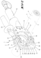
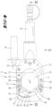
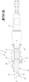
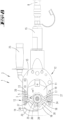
FIG. 1 shows a device for the severance of an electrical power cable in the form of a cutting device in the use state; -
FIG. 2 shows the device in perspective illustration relating to an initial position; -
FIG. 3 shows a perspective rear view for this; -
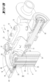
FIG. 4 shows the device in side view; -
FIG. 5 shows the device in bottom view; -
FIG. 6 shows the device in a perspective exploded illustration; -
FIG. 7 shows an illustration, which corresponds toFIG. 4 , comprising a strand section to be severed in the form of a power cable; -
FIG. 8 shows an illustration, which corresponds toFIG. 7 , but in the course of the cutting process; -
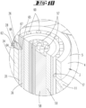
FIG. 9 shows the perspective section along line IX-IX inFIG. 4 ; -
FIG. 10 shows the enlargement of the region X inFIG. 9 ; -
FIG. 11 shows an illustration, which corresponds toFIG. 3 , but after complete severance of the strand section; -
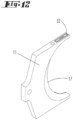
FIG. 12 shows a movable cutting blade of the device in a perspective individual illustration; -
FIG. 13 shows an illustration, which corresponds toFIG. 2 , relating to a further embodiment with open cutting head; -
FIG. 14 shows a view of a further embodiment of the device; -
FIG. 15 shows a view of the device in a further embodiment; -
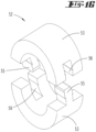
Fig 16 shows an adapter for surrounding a strand-shaped item to be cut in a perspective individual illustration; -
FIG. 17 shows an illustration, which corresponds toFIG. 4 , of the device prior to severance of a strand-shaped item to be cut in the form of a power cable, which is provided with the adapter; -
FIG. 18 shows an illustration, which corresponds toFIG. 17 , but relating to the cutting or test position, respectively, according toFIG. 8 ; -
FIG. 19 shows the adapter in a further embodiment; -
FIG. 20 shows a cross-sectional view of an electrical probe according to a further aspect; -
FIG. 21 shows a cross-sectional view of an electrical probe according to yet another aspect; -
FIGS. 22A and 22B show a cross-sectional views of an electrical probe according to yet an even further aspect; and -
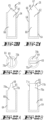
FIGS. 22C and 22D show top plan views of the electrical probe ofFIGS. 22A and 22B . - A
device 1 in the form of ahydraulic cutting device 2 for the severance of a strand-shaped item to be cut 3, in particular astrand section 4, and, as illustrated, apower cable 5, is illustrated and described with reference toFIG. 1 . Insofar as reference is made below to thepower cable 5, the disclosure is also relevant for a strand-shaped item to be cut or a strand section, respectively, insofar as a voltage admission, as might possibly be present in the case of the electrical power cable, is not important. Theelectrical power cable 5 is a high voltage power cable. -
FIG. 1 schematically illustrates a situation, in which thepower cable 5, which is to be severed, is installed as item to be cut 3 in an exposedtrench 6. - The
cutting device 2 can be remotely controlled, by a control device 7, which is hydraulically and, if applicable, also electrically connected with thecutting device 2. A connecting dielectric hydraulic hose is provided withreference numeral 8. - The control device 7 has at least one
activation switch 9. By actuating theactivation switch 9, an electrically actuated hydraulic pump is activated in the control device 7 for conveying hydraulic oil from a hydraulic reservoir into a piston chamber, which is provided in thecutting device 2. - The hydraulic pump moves a
piston 10 in thecutting device 2. Amovable cutting blade 11 is fastened to thepiston 10. - The
cutting device 2 or thedevice 1, respectively, has a cuttinghead 12. It is formed in a frame-like manner for encompassing the item to be cut 3. The cuttinghead 12 includes astationary frame section 13 and aframe section 14, which are pivotally connected to each other. Theframe section 14 defines apivotable frame section 14. Theframe section 14 may be at least partially formed of a plate which is generally U-shaped such that an opening is defined. Theframe section 13 may be formed of a pair of plates which are joined together such that an essentially forked layout is defined. The plates offrame section 13 may be generally U-shaped such that an opening is defined. Theframe section 14 seats between the plates forming theframe section 13 and the openings face each other. - The
stationary frame section 13 is connected to ahandling section 15, in which, among others, the afore-describedpiston 10 is arranged so as to be linearly shiftable such that thepiston 10 is moveable relative to thestationary frame section 13. - First and
second cutting blades head 12. Thecutting blade 11 has acutting edge 17. Thecutting blade 16 has acutting edge 18. Themovable cutting blade 11, which is connected with thepiston 10, is attached to and guided within thestationary frame section 13. Thestationary cutting blade 16 is attached to and guided within thepivotable frame section 14. Thecutting blades - The
movable cutting blade 11 can be displaced relative to thestationary cutting blade 16 along a cutting plane E, seeFIG. 5 . - With respect to the cutting plane E, the
cutting blades 11, 16 (seeFIG. 5 , in which the cutting plane E is illustrated as a line) are arranged laterally offset relative to one another. Thecutting blades movable cutting blade 11 is moved past thestationary cutting blade 16 to the extent that the cutting edges 17, 18 overlap for complete severance of an item to be cut 3. - The
pivotable frame section 14 is attached to thestationary frame section 13 so as to be capable of being pivoted about abolt 19 which defines an axis x, seeFIG. 5 . The axis x is oriented vertically to the cutting plane E. For this purpose, an end of thepivotable frame section 14 seats between the plates of thestationary frame section 13. The pivotable mount is provided by thebolt 19, which extends through the plates of thestationary frame section 13 and the assigned end of thepivotable frame section 14. - Due to the pivotability of the
frame section 14 and thestationary cutting blade 16 mounted thereon, a cutting process, in which the cuttinghead 12 is initially placed around the item to be cut 13 when the cuttinghead 12 is pivoted, can in particular be executed in the case of a very long item to be cut 3 and/or as a function of the locality, for example in the case of an installedpower cable 5. - As a result of pivoting the
frame section 14 back into a position in which thecutting edge 18 of thestationary cutting blade 16 is located opposite to thecutting edge 17 of themovable cutting blade 11 in the direction of displacement r thereof, the cuttinghead 12 is closed after this. - The operating position shown in
FIG. 2 can be fixed, for example, in a hold-open position. - In the disclosure, a locking
bolt 20, which is oriented parallel to thebolt 19 and which can be displaced in axial direction of the bolt, serves this purpose. - The locking
bolt 20 is held and guided in thestationary frame section 13 and has ahandling collar 21, which can be seized manually. - In a locked position, the locking
bolt 20 extends through a lockingaperture 22 of thepivotable frame section 14 and has a free end which extends into a receivinghole 23 in one of the plates forming thestationary frame section 13. - The locking
bolt 20 is spring-loaded towards this locked position. - An unlocking for releasing the
pivotable frame section 14 can be attained by powerfully displacing the lockingbolt 20 in axial direction thereof against the spring force, until the lockingbolt 20 leaves the lockingaperture 22 of thepivotable frame section 14. This allows thepivotable frame section 14 to pivot relative to thestationary frame section 13 aroundbolt 19 as shown inFIG. 13 . - As illustrated in
FIG. 13 , the position of the lockingbolt 20, in particular the locked position, can be registered in a sensory manner by registering the position of the free end of the lockingbolt 20, which faces away from the handlingcollar 21, in the receivinghole 23. For this purpose, a correspondingsensor 24, seeFIG. 13 , can be arranged in the region of the receivinghole 23. This can be a proximity sensor or also a contact sensor. - Provision can furthermore be made on the
stationary frame section 13 for afurther handle 25. - The
cutting device 2 ordevice 1, respectively, is provided with a measuring device 61 which includes anelectrical measuring probe 26 and an evaluation and/ortransmission controller 29 which are electrically connected together. - As is illustrated, the measuring
probe 26 may be embodied as aspike 62 having aninsulative sheath 64 surrounding the portions of which are to remain electrically isolated from thecutting device 2 ordevice 1, and aspike tip 65 having a portion thereof which remains exposed. Theinsulative sheath 64 may be formed of ceramic. Thespike tip 65 is conductive. As shown inFIG. 10 , thespike 62 has acylindrical section 66 having acone 67 attached to an end of thecylindrical section 66. Thespike tip 65 is formed by part of thecone 67. Theinsulative sheath 64 surrounds thecylindrical section 66 and part of thecone 67. As shown inFIG. 20 , theinsulative sheath 64 only surrounds thecylindrical section 66 and thespike tip 65 is formed by thecone 67. InFIG. 21 , theinsulative sheath 64 extends along a majority of thecylindrical section 66, but leaves anouter shoulder 68 of thecylindrical section 66 exposed. Thespike tip 65 is formed by thecone 67 and theshoulder 68.FIGS. 22A and 22B show that thespike 62 has acylindrical section 66 having a protrudingspike tip 65 formed therewith. Thespike tip 65 has anouter surface 69 which is planar, a first pair of opposingside surfaces cylindrical section 66 to theouter surface 69, and a second pair of opposingside surfaces 71a, 71b which follow along the line of an imaginary cylinder. Theinsulative sheath 64 surrounds thecylindrical section 66. The radiused side surfaces may follow a single radius or multiple radii which are joined together to form the respective side surface. - In the disclosure, the measuring
probe 26 is provided on thepivotable frame section 14. The measuringprobe 26 is arranged in a plane parallel to the cutting plane E, in particular facing the side of thestationary cutting blade 16, which faces away from themovable cutting blade 11. - The
spike 62 of the measuringprobe 26 is parallel to the cutting plane E. The spike 62 is oriented such that thespike 62 faces toward thestationary cutting blade 16 when the cuttinghead 12 is closed. Thespike 62 may be provided in the center of the longitudinal extension of thecutting edge 18 of thecutting blade 16, wherein thespike 62 of the measuringprobe 26 is directed in repositioning direction of themovable cutting blade 11 in the operating position, that is, when the cuttinghead 12 is closed. - The measuring
probe 26, in particular thespike tip 65, projects freely beyond the cuttingedge 18 of thecutting blade 16 into acutting device aperture 27, which is formed between the cuttingedges 18 when the cuttinghead 12 is closed and thecutting blades probe 26, in particular thespike tip 65 thereof, is arranged upstream of thestationary cutting blade 16 in the course of a cutting process. - As shown, the measuring
probe 26 is electrically connected with the evaluation and/ortransmission controller 29 via aline 28. Theline 28 leads from the measuringprobe 26 at least partially through thepivotable frame section 14, if applicable guided in a trough-like depression 30, which is embodied on a broadside of thepivotable frame section 14. While aline 28 is shown, it is to be understood that the measuringprobe 26 may be electrically connected with the evaluation and/ortransmission controller 29 via a wireless connection. - The evaluation and/or
transmission controller 29 includes, amongst other components, a transceiver, a processor, software, memory, digital logic, for carrying out its functions. - The evaluation and/or
transmission controller 29 is fastened to thepivotable frame section 14, and may be fastened to the side of thestationary cutting blade 16, which faces away from the measuringprobe 26. - The evaluation and/or
transmission controller 29 can furthermore be positioned on thepivotable frame section 14 in such a manner that themovable cutting blade 11 moves underneath evaluation and/ortransmission controller 29 in the course of a cutting process. - The evaluation and/or
transmission controller 29 may have its own power supply. For this purpose, provision can be made in the evaluation and/ortransmission controller 29 for a battery or an accumulator, for example, - According to an aspect of the disclosure, the measuring
probe 26, in particular thespike 62, which is electrically connected with theline 28, is embodied as electrical conductor, which is in contact with the evaluation and/ortransmission controller 29 via theline 28. A measuring value is registered in the evaluation and/ortransmission controller 29 and is evaluated to determine whether this measuring value corresponds to or exceeds a predetermined maximum. A signal, which is sent out via the evaluation and/ortransmission controller 29, is generated as a function of the evaluation result. - The evaluation and/or
transmission controller 29 can transfer the signal to a receivingcontroller 31, seeFIG. 1 , via radio. In the altemative, for example in the event of an additional electrical supply of thecutting device 2 via the control device 7, if applicable, the signal can also be forwarded to the control device 7 via an additionally provided data line or by modulation. - In the event of a radio transmission, the control device 7 has a corresponding receiving
controller 31. - Furthermore, the evaluation and/or
transmission controller 29 can also evaluate a locking signal from thesensor 24. Provision can thus be made for a cutting process to be released only in the event of a generation of a corresponding locking signal which is generated when cuttinghead 12 is closed and is locked via lockingbolt 20. In this case, thecutting device 2 can be activated via theactivation switch 9 only by registering the locking signal transmitted via the evaluation and/ortransmission controller 29. - A successful completion of the cutting process can also be detected by the evaluation and/or
transmission controller 29. The end position of themovable cutting blade 11 illustrated inFIG. 11 , for example, in which thecutting edge 17 of themovable cutting blade 11 is moved completely beyond the cuttingedge 18 of thestationary cutting blade 16, can thus be detected. For this purpose, themovable cutting blade 11 can have apassive sensor 32, seeFIG. 12 , which can be interrogated by anactive sensor 33, seeFIG. 11 , here by the evaluation and/ortransmission controller 29. - As shown in
FIG. 12 , thepassive sensor 32 may be formed as a RFID unit, which is arranged on an edge surface of themovable cutting blade 11, which faces the evaluation and/ortransmission controller 29. - The
passive sensor 32 illustrated inFIG. 12 can also be a reflector unit, which reflects light emitted by the evaluation and/ortransmission controller 29 for the detection of the cutting blade position. - A correspondingly generated signal in the event of the registration of the
passive sensor 32 triggers an optical or acoustic signal, for example, which conveys to the user that the cutting process has ended. In the alternative or as a combination to this, an automatic return of themovable cutting blade 11 can also be triggered. - A measurement with regard to the electrical load of the
power cable 5 is executed by the measuringprobe 26 in the course of the severance of apower cable 5 for the transmission of high voltage. - As best shown in
FIG. 10 , thepower cable 5 hasinternal conductors 57, for example copper conductors, which are embodied for guiding voltage, which are embedded in an insulatingmaterial 58 and which are surrounded by it. As a whole, theconductors 57 and the insulatingmaterial 58 can be surrounded by an insulating layer 59 (for example including cross-linked polyethylene or rubber). - A
conductive sheath 36 surrounds the outside of the insulatinglayer 59. - A
screening layer 35 surrounds the outside of theconductive sheath 36. The screening layer can include, for example, a plurality of spaced apartcopper wires 60, which are tin-plated, if applicable. - A
cable sheath 34 forms an outer surface of thepower cable 5 surrounding it on the outside. Thecable sheath 34 includes a cross-linked polyethylene (XLPE) and mechanically protects thescreening layer 35 located therebelow. - In the course of moving the
movable cutting blade 11 forward, thepower cable 5, which is seated within thecutting device aperture 27, is displaced out of a retracted initial position and is moved towards the fixedcutting blade 13 and towards the measuringprobe 26. Upon the further movement of thecutting blade 11, thecutting blade 11 applies pressure on thepower cable 5 and cuts thepower cable 5 until thecutting blade 11 contacts thescreening layer 35 to electrically couple thescreening layer 35 and thecutting blade 11 together. When the measuringprobe 26 contacts thepower cable 5, the measuringprobe 26 penetrates thecable sheath 34 and the screening layer 35 (or thespike 62 of the measuringprobe 26 may pass betweenadjacent wires 60 which form the screening layer 35) and thetip 65 of the electricallyconductive spike 62 penetrates into theconductive sheath 36 to electrically couple theconductive sheath 36 and thespike 62 of the measuringprobe 26 - The fixed
cutting blade 16 is shifted backwards relative to the measuringprobe 26 such that the fixedcutting blade 16 does not contact thescreening layer 35. - A continuous voltage measurement is made between the measuring
probe 26 and the device ground via thecutting blade 11 during the cutting process. - The cutting process runs such that an outer layer of the
power cable 5, thecable sheath 34, is severed at two locations in a first step. These two locations can be at located opposite one another relative to thepower cable 5, as is also illustrated in the FIGURES. On principle, two adjacent locations across the length of thepower cable 5 can also be used for this purpose. - The severance of an outer layer, in particular of the
cable sheath 34, has the effect or is executed to the extent, respectively, that the cutting blade 11is in contact with thewires 60 of thescreening layer 35. Thewires 60 are arranged below the outer layer, thus below thecable sheath 34 or on the inside of thecable sheath 34, respectively. - A cut is made into the
power cable 5 by the measuringprobe 26, namely to the extent that thewires 60 are cut through and that the measuringprobe 26 contacts thesheath 36. A resistance measurement is then executed between the measuringprobe 26 and the devie ground via the cutting blade 11which is electrically coupled to thescreening layer 35. - Finally, a voltage measurement between the measuring
probe 26 when in contact with theconductive sheath 36 and the device ground via thecutting blade 11 when in contact with thescreening layer 35 is executed. In the event that a voltage can be measured hereby, thepower cable 5 is under voltage, thus "live". - Accordingly, a
power cable 5, which is under high voltage, leads to a measurable voltage at thescreening layer 35. - A high voltage loaded
power cable 5 leads to a measurable voltage at thescreening layer 35 to ground or against thecutting blade 11 in the millivolt or single-digit Volt range. - In the event of the determination of a corresponding voltage, if applicable in the event of the determination of a predetermined maximum voltage and corresponding evaluation, a signal is generated and is transmitted directly to the
device 1 or to the control device 7 via the evaluation and/ortransmission controller 29. An optical or acoustic signal can be emitted, which is to prompt the user to terminate the cutting process. The signal triggers an automatic termination of the cutting process, if applicable a subsequent return of themovable cutting blade 11 into the initial position wherein thecutting blade 11 is disengaged from thepower cable 5. - If applicable, the signals transmitted to the control device 7 can be recorded in the control device 7.
- Provision can also be made in the control device 7 for a display, on which measuring values of the measuring
probe 26 are continually illustrated in a graphic manner. - In particular, in the event of a cutting of
electrical power cables 5, but furthermore also in the case of another item to be cut 3, it is necessary to push the item to be cut 3 transverse to the direction of displacement r towards a central region of both cuttingblades movable cutting blade 11. In particular, in the case of the arrangement of the measuringprobe 26 and of a cutting of thepower cable 5, which is to be carried out, a guided displacement of thepower cable 5 towards the centrally arranged measuringprobe 26 is advantageous in the case of apower cable 5, which has a smaller cross-section than thecutting device aperture 27, so as to be able to correctly execute a voltage test, which is provided as described above. - As shown in
FIGS. 1-13 , the cuttinghead 12, in particular thepivotable frame section 14, is provided with twopositioning parts positioning parts pivotable frame section 14, on the flat side of theframe section 14, which faces away from the evaluation and/ortransmission controller 29, wherein the pivot axis of thepositioning parts frame section 14. -
Bolts pivotable frame section 14. Thepositioning parts bolts springs - Starting at the
bolts positioning parts spike 62 of the measuringprobe 26 seated between thepositioning parts spike 62 is within thecutting device aperture 27. The curvature of thepositioning parts movable cutting blade 11. Free ends of thepositioning parts probe 26. - A V-shaped constriction of the
cutting device aperture 27 is formed by thepositioning parts probe 26. As a result, an item to be cut 3, for example apower cable 5, is pushed automatically towards the centrally oriented measuringprobe 26 by slow displacement via themovable cutting blade 11. - The
positioning parts springs bolts -
FIG. 14 showsalternative positioning parts positioning parts cutting device aperture 27 in the direction of displacement r. The twopositioning parts journal 43 of thepivotable frame section 14, which connects the ends of thepivotable frame section 14, on both sides of this axis. The measuringprobe 26 is positioned on thejournal 43 between thepositioning parts positioning parts journal 43 bybolts positioning parts bolts - The support regions of the
positioning parts gear wheels positioning part gear wheels other positioning part - The orientation of the
positioning parts screw 46. Provision can also be made at thejournal 43 for markings in the form of numbers, by a pre-adjustment can be made so as to be matched to the outer diameter dimensions of the item to be cut 3. - Provision can furthermore be made for only one
positioning part 37 as a carriage, which is supported in the direction of displacement r of the movable cutting blade 11 (seeFIG. 15 ). - The
positioning part 37 of the embodiment inFIG. 15 is formed in a plate-shaped manner, hereby bears on a broadside of thepivotable frame section 14, on the broadside, which faces away from the evaluation and/ortransmission controller 29. - The
positioning part 37 has two elongatedholes pivotable frame section 14. While the guide pins 49, 50 are shown on theframe section 14 and theholes positioning part 37, it is to be understood that the guide pins 49, 50 can be provided on thepositioning part 37 and theholes frame section 14. - This provides for a linear guide for the
positioning part 37, wherein tension springs 51 acting on thepositioning part 37 to load thepositioning part 37 towards themovable cutting blade 11. - An outer edge of the
positioning part 37, which faces themovable cutting blade 11, is formed as in a V-shape in relation to thespike 62 into the cutting plane E, hereby in each case from the outside towards thejournal 43 of thepivotable frame section 14 rising towards the center of thepositioning part 37. - An item to be cut 3, which is seated within the
cutting device aperture 27, is also pushed via themovable cutting blade 11 along the facing outer edges of thepositioning part 37 to the center of thecutting device aperture 27, wherein thepositioning part 37 is able to give way in the direction of displacement r in the course of the cutting process. - While the
positioning part 37 orpositioning parts frame section 14 which houses thestationary cutting blade 16, it is to be understood that thepositioning part 37 orpositioning parts frame section 13 which houses themoveable cutting blade 11. - Provision can furthermore be made for an
adapter 52, seeFIG. 16 , for centering an item to be cut 3 in thecutting device aperture 27. - The
adapter 52 is a part which, as a whole, has the shape of a pipe section, and is made of a material which can be cut quickly, such as foam or soft plastic, for example. Theadapter 52 may have a circular layout. - The
adapter 52 has an outer cross-sectional contour, which is matched to the cross-sectional contour of thecutting device aperture 27. The cross-sectional inner contour of theadapter 52 is matched or, due to the material selection, can be matched to the outer cross-section of the item to be cut 3 (here of apower cable 5; seeFIGS. 16-18 ). - The
adapter 52 may be formed in two parts, wherein both parts substantially formhalf shells 53. For pivoting and for surrounding the item to be cut 3, thehalf shells 53 can be connected with one another, for example via a hinge-like bond seam 54 (seeFIG. 19 ). - According to
FIG. 16 , thehalf shells 53 can alternatively have pins 55, which project beyond the parting plane of theadapter 52, for positive accommodation in correspondingly embodiedgrooves 56. This can be a dove tail-like undercut. - As can be seen in particular from the illustration in
FIG. 18 , the centered arrangement of an item to be cut 3 can be attained in thecutting device aperture 27 by using such anadapter 52. This leads to a favorable cross-section. - When cutting a
power cable 5, it is furthermore ensured that a corresponding measuringprobe 26, which is positioned in the center, securely penetrates thepower cable 5 after penetrating theadapter 52 in the course of the cutting process for penetrating into theconductive sheath 36 so as to test the voltage. - The
adapter 52 is severed in the course of the cutting process. - The
spike 62 of the measuringprobe 26 can be embodied as thecutting blade 16 having an insulative sheath (not shown), like that ofinsulative sheath 64, surrounding the portions of which are to remain electrically isolated from thecutting device 2 ordevice 1, with thecutting edge 18 remaining exposed and forming the spike tip, like that ofspike tip 65. Like that ofinsulative sheath 64, the insulative sheath partially surrounding thecutting blade 16 may be formed of ceramic. - The
sensors transmission controller 29. Such communication may be done via wires or wirelessly. - The severance of an outer layer, in particular of the
cable sheath 34, has the effect or is executed to the extent, respectively, that the cutting blade 11is in contact with thewires 60 of thescreening layer 35. Thewires 60 are arranged below the outer layer, thus below thecable sheath 34 or on the inside of thecable sheath 34, respectively. - A cut is made into the
power cable 5 by the measuringprobe 26, namely to the extent that thewires 60 are cut through and that the measuringprobe 26 contacts thesheath 36. A resistance measurement is then executed between the measuringprobe 26 and the devie ground via the cutting blade 11which is electrically coupled to thescreening layer 35. - Finally, a voltage measurement between the measuring
probe 26 when in contact with theconductive sheath 36 and the device ground via the cutting blade 11when in contact with thescreening layer 35 is executed. In the event that a voltage can be measured hereby, thepower cable 5 is under voltage, thus "live". - Accordingly, a
power cable 5, which is under high voltage, leads to a measurable voltage at thescreening layer 35. - A high voltage loaded
power cable 5 leads to a measurable voltage at thescreening layer 35 to ground or against thecutting blade 11 in the millivolt or single-digit Volt range. - In the event of the determination of a corresponding voltage, if applicable in the event of the determination of a predetermined maximum voltage and corresponding evaluation, a signal is generated and is transmitted directly to the
device 1 or to the control device 7 via the evaluation and/ortransmission controller 29. An optical or acoustic signal can be emitted, which is to prompt the user to terminate the cutting process. The signal triggers an automatic termination of the cutting process, if applicable a subsequent return of themovable cutting blade 11 into the initial position wherein thecutting blade 11 is disengaged from thepower cable 5. - If applicable, the signals transmitted to the control device 7 can be recorded in the control device 7.
- Provision can also be made in the control device 7 for a display, on which measuring values of the measuring
probe 26 are continually illustrated in a graphic manner. - In particular, in the event of a cutting of
electrical power cables 5, but furthermore also in the case of another item to be cut 3, it is necessary to push the item to be cut 3 transverse to the direction of displacement r towards a central region of both cuttingblades movable cutting blade 11. In particular, in the case of the arrangement of the measuringprobe 26 and of a cutting of thepower cable 5, which is to be carried out, a guided displacement of thepower cable 5 towards the centrally arranged measuringprobe 26 is advantageous in the case of apower cable 5, which has a smaller cross-section than thecutting device aperture 27, so as to be able to correctly execute a voltage test, which is provided as described above. - As shown in
FIGS. 1-13 , the cuttinghead 12, in particular thepivotable frame section 14, is provided with twopositioning parts positioning parts pivotable frame section 14, on the flat side of theframe section 14, which faces away from the evaluation and/ortransmission controller 29, wherein the pivot axis of thepositioning parts frame section 14. -
Bolts pivotable frame section 14. Thepositioning parts bolts springs - Starting at the
bolts positioning parts spike 62 of the measuringprobe 26 seated between thepositioning parts spike 62 is within thecutting device aperture 27. The curvature of thepositioning parts movable cutting blade 11. Free ends of thepositioning parts probe 26. - A V-shaped constriction of the
cutting device aperture 27 is formed by thepositioning parts probe 26. As a result, an item to be cut 3, for example apower cable 5, is pushed automatically towards the centrally oriented measuringprobe 26 by slow displacement via themovable cutting blade 11. - The
positioning parts springs bolts -
FIG. 14 showsalternative positioning parts positioning parts cutting device aperture 27 in the direction of displacement r. The twopositioning parts journal 43 of thepivotable frame section 14, which connects the ends of thepivotable frame section 14, on both sides of this axis. The measuringprobe 26 is positioned on thejournal 43 between thepositioning parts positioning parts journal 43 bybolts positioning parts bolts - The support regions of the
positioning parts gear wheels positioning part gear wheels other positioning part - The orientation of the
positioning parts screw 46. Provision can also be made at thejournal 43 for markings in the form of numbers, by a pre-adjustment can be made so as to be matched to the outer diameter dimensions of the item to be cut 3. - Provision can furthermore be made for only one
positioning part 37 as a carriage, which is supported in the direction of displacement r of the movable cutting blade 11 (seeFIG. 15 ). - The
positioning part 37 of the embodiment inFIG. 15 is formed in a plate-shaped manner, hereby bears on a broadside of thepivotable frame section 14, on the broadside, which faces away from the evaluation and/ortransmission controller 29. - The
positioning part 37 has two elongatedholes pivotable frame section 14. While the guide pins 49, 50 are shown on theframe section 14 and theholes positioning part 37, it is to be understood that the guide pins 49, 50 can be provided on thepositioning part 37 and theholes frame section 14. - This provides for a linear guide for the
positioning part 37, wherein tension springs 51 acting on thepositioning part 37 to load thepositioning part 37 towards themovable cutting blade 11. - An outer edge of the
positioning part 37, which faces themovable cutting blade 11, is formed as in a V-shape in relation to thespike 62 into the cutting plane E, hereby in each case from the outside towards thejournal 43 of thepivotable frame section 14 rising towards the center of thepositioning part 37. - An item to be cut 3, which is seated within the
cutting device aperture 27, is also pushed via themovable cutting blade 11 along the facing outer edges of thepositioning part 37 to the center of thecutting device aperture 27, wherein thepositioning part 37 is able to give way in the direction of displacement r in the course of the cutting process. - While the
positioning part 37 orpositioning parts frame section 14 which houses thestationary cutting blade 16, it is to be understood that thepositioning part 37 orpositioning parts frame section 13 which houses themoveable cutting blade 11. - Provision can furthermore be made for an
adapter 52, seeFIG. 16 , for centering an item to be cut 3 in thecutting device aperture 27. - The
adapter 52 is a part which, as a whole, has the shape of a pipe section, and is made of a material which can be cut quickly, such as foam or soft plastic, for example. Theadapter 52 may have a circular layout. - The
adapter 52 has an outer cross-sectional contour, which is matched to the cross-sectional contour of thecutting device aperture 27. The cross-sectional inner contour of theadapter 52 is matched or, due to the material selection, can be matched to the outer cross-section of the item to be cut 3 (here of apower cable 5; seeFIGS. 16-18 ). - The
adapter 52 may be formed in two parts, wherein both parts substantially formhalf shells 53. For pivoting and for surrounding the item to be cut 3, thehalf shells 53 can be connected with one another, for example via a hinge-like bond seam 54 (seeFIG. 19 ). - According to
FIG. 16 , thehalf shells 53 can alternatively have pins 55, which project beyond the parting plane of theadapter 52, for positive accommodation in correspondingly embodiedgrooves 56. This can be a dove tail-like undercut. - As can be seen in particular from the illustration in
FIG. 18 , the centered arrangement of an item to be cut 3 can be attained in thecutting device aperture 27 by using such anadapter 52. This leads to a favorable cross-section. - When cutting a
power cable 5, it is furthermore ensured that a corresponding measuringprobe 26, which is positioned in the center, securely penetrates thepower cable 5 after penetrating theadapter 52 in the course of the cutting process for penetrating into theconductive sheath 36 so as to test the voltage. - The
adapter 52 is severed in the course of the cutting process. - The
spike 62 of the measuringprobe 26 can be embodied as thecutting blade 16 having an insulative sheath (not shown), like that ofinsulative sheath 64, surrounding the portions of which are to remain electrically isolated from thecutting device 2 ordevice 1, with thecutting edge 18 remaining exposed and forming the spike tip, like that ofspike tip 65. Like that ofinsulative sheath 64, the insulative sheath partially surrounding thecutting blade 16 may be formed of ceramic. - The
sensors transmission controller 29. Such communication may be done via wires or wirelessly. -
- 1
- device
- 2
- cutting device
- 3
- item to be cut
- 4
- strand section
- 5
- power cable
- 6
- trench
- 7
- control device
- 8
- hydraulic hose
- 9
- activation switch
- 10
- piston
- 11
- movable cutting blade
- 12
- cutting head
- 13
- frame section
- 14
- frame section
- 15
- handling section
- 16
- cutting blade
- 17
- cutting edge
- 18
- cutting edge
- 19
- bolt
- 20
- locking bolt
- 21
- handling collar
- 22
- locking aperture
- 23
- receiving hole
- 24
- sensor
- 25
- handle
- 26
- measuring probe
- 27
- cutting device aperture
- 28
- line
- 29
- evaluation and/or transmission controller
- 30
- depression
- 31
- receiving controller
- 32
- passive sensor
- 33
- active sensor
- 34
- cable sheath
- 35
- screening layer
- 36
- conductive sheath
- 37
- positioning part
- 38
- positioning part
- 39
- bolt
- 40
- bolt
- 41
- spring
- 42
- spring
- 43
- journal
- 44
- gear wheel embodiment
- 45
- gear wheel embodiment
- 46
- screw
- 47
- elongated hole
- 48
- elongated hole
- 49
- guide pin
- 50
- guide pin
- 51
- tension spring
- 52
- adapter
- 53
- half shell
- 54
- bond seam
- 55
- pin
- 56
- groove
- 57
- conductor
- 58
- insulating material
- 59
- insulating layer
- 60
- wire
- 62
- spike
- 64
- insulative sheath
- 65
- spike tip
- 66
- cylindrical section
- 67
- cone
- 68
- outer shoulder
- 69
- outer surface
- 70a, 70b
- opposing side surfaces
- 71a, 71b
- opposing side surfaces
- r
- direction of displacement
- x
- axis
- E
- cutting plane
Claims (2)
- A hydraulically or electrically actuatable cutting device comprising a cutting head, a sensor and an evaluation controller, the cutting head is formed so as to encompass an item to be cut, with a first movable (11) and a second stationary cutting blade (16), which can be traversed linearly relative to one another, wherein the movable cutting blade (11) can be registered with regard to its position via the sensor (32, 33), comprising an active sensor (33) and a passive sensor (32), wherein for detection of a completion of a cutting process by the evaluation controller (29) an end position of the first cutting blade (11) moved completely beyond a cutting edge (18) of the second cutting blade (16) can be detected, for which purpose the first cutting blade (11) has the passive sensor (32) which is interrogated by the active sensor (33) by the evaluation controller (29), wherein the passive sensor (32) is a magnet, RFID unit and/or reflector unit, wherein the cutting head (12) is formed in a frame-like manner for encompassing the item to be cut (3), the cutting head includes a stationary frame section (13) and a frame section (14), which are pivotably connected to each other, wherein the frame section (14) defines a pivotable frame section (14) least partially formed of a plate which is generally U-shaped such that an opening is defined, wherein the stationary frame section (13) is formed of a pair of plates, which are joined together such that an essentially forked layout is defined, wherein the plates of the stationary frame section (13) are generally U-shaped such that an opening is defined, wherein the pivotable frame section (14) seats between the plates forming the stationary frame section (13) and the openings face each other, wherein the pivotable frame section (14) is attached to the stationary frame section (13) to be capable of being pivoted about a bolt (19), which defines an axis (x), wherein the axis (x) is oriented vertically to the cutting plane (E), wherein an end of the pivotable frame section (14) seats between the plates of the stationary frame section (13), wherein a pivotable mount is provided by the bolt (19), which extends through the plates in the stationary frame section (13) and the assigned end of the pivotable frame section (14), wherein an operating position of the pivotable frame section (14) can be fixed in a hold open position by a locking bolt (20) of the cutting device, which is oriented parallel to the bolt (19) and which can be displaced in axial direction of the bolt, wherein a position of the locking bolt (20), in particular the locked position, can be registered in a sensory manner by registering the position of the free end of the locking bolt (20) which faces away from a handling collar (21) of the locking bolt (20), in the receiving hole (23), wherein a corresponding sensor (34) of the cutting device is arranged in the region of the receiving hole (23) which is a proximity sensor or a contact sensor, and wherein the evaluation and/or transmission controller does evaluate a locking signal from the sensor (24) such that provision can be made for cutting process to be released only in the event of a generation of corresponding locking signal which is generated when the cutting head (12) is closed and is locked via locking bolt (20) in which case the cutting device (2) can be activated via an activation switch (9) only by registering the locking signal transmitted via the evaluation and/or transmission controller (29).
- The device according to claims 1, wherein the active sensor (33) is accommodated in the controller (29) of the device.
Priority Applications (1)
| Application Number | Priority Date | Filing Date | Title |
|---|---|---|---|
| EP25186553.1A EP4599967A3 (en) | 2015-01-07 | 2016-01-07 | Cutting device |
Applications Claiming Priority (2)
| Application Number | Priority Date | Filing Date | Title |
|---|---|---|---|
| US201562100639P | 2015-01-07 | 2015-01-07 | |
| PCT/US2016/012417 WO2016112153A2 (en) | 2015-01-07 | 2016-01-07 | Method for the severance of an electrical power cable, or of a strand section, device therefor, as well as cutting device |
Related Child Applications (1)
| Application Number | Title | Priority Date | Filing Date |
|---|---|---|---|
| EP25186553.1A Division EP4599967A3 (en) | 2015-01-07 | 2016-01-07 | Cutting device |
Publications (2)
| Publication Number | Publication Date |
|---|---|
| EP3243250A2 EP3243250A2 (en) | 2017-11-15 |
| EP3243250B1 true EP3243250B1 (en) | 2025-07-02 |
Family
ID=55353282
Family Applications (2)
| Application Number | Title | Priority Date | Filing Date |
|---|---|---|---|
| EP16704284.5A Active EP3243250B1 (en) | 2015-01-07 | 2016-01-07 | Method for the severance of an electrical power cable, or of a strand section, device therefor, as well as cutting device |
| EP25186553.1A Pending EP4599967A3 (en) | 2015-01-07 | 2016-01-07 | Cutting device |
Family Applications After (1)
| Application Number | Title | Priority Date | Filing Date |
|---|---|---|---|
| EP25186553.1A Pending EP4599967A3 (en) | 2015-01-07 | 2016-01-07 | Cutting device |
Country Status (6)
| Country | Link |
|---|---|
| US (2) | US20180006437A1 (en) |
| EP (2) | EP3243250B1 (en) |
| KR (1) | KR102579230B1 (en) |
| CN (2) | CN107112730B (en) |
| CA (1) | CA2969247C (en) |
| WO (1) | WO2016112153A2 (en) |
Families Citing this family (20)
| Publication number | Priority date | Publication date | Assignee | Title |
|---|---|---|---|---|
| CN105021929B (en) * | 2015-08-04 | 2017-11-14 | 南京新联电子股份有限公司 | Integrated small intelligent electric power acquisition module |
| US10651636B2 (en) | 2015-08-07 | 2020-05-12 | Hubbell Incorporated | Portable hand tool and kit |
| WO2018064754A1 (en) * | 2016-10-05 | 2018-04-12 | Hydro-Quebec | Resistance-measuring device and method |
| EP3333994B1 (en) * | 2016-12-09 | 2020-03-18 | CEMBRE S.p.A. | Working head for a compression or cutting tool |
| IT201600124520A1 (en) * | 2016-12-09 | 2018-06-09 | Cembre Spa | SYSTEM FOR CUTTING ELECTRIC CABLES |
| CN107039915A (en) * | 2017-06-20 | 2017-08-11 | 国网辽宁省电力有限公司抚顺供电公司 | 10kV cable insulation damage detector for electrical |
| AU2018302427B2 (en) * | 2017-07-17 | 2024-03-21 | Gustav Klauke Gmbh | Tool for cutting a workpiece |
| NO344001B1 (en) * | 2017-11-29 | 2019-08-12 | Smart Installations As | Method for cutting a tubular structure at a drill floor and a cutting tool for carrying out such method |
| US10727637B2 (en) * | 2018-01-02 | 2020-07-28 | Jeffrey C. Lemke | Cutting fixture exhibiting ram actuated and multiplying lever force for removing such as an H-tap crimp from a utility power line |
| EP3799581B1 (en) * | 2018-05-18 | 2022-10-19 | Gustav Klauke GmbH | Working device having a hydraulic cylinder and manual working device such as a pliers or a press |
| DE202018003442U1 (en) * | 2018-07-25 | 2019-10-28 | Ipr Gmbh | Cable assembly tooling |
| CN109332794A (en) * | 2018-11-30 | 2019-02-15 | 国网安徽省电力有限公司蚌埠供电公司 | High-voltage lead intelligent cutting device |
| US11878402B2 (en) | 2019-03-18 | 2024-01-23 | Milwaukee Electric Tool Corporation | Hydraulic power tool |
| CN109807367B (en) * | 2019-03-22 | 2023-11-14 | 曹春博 | Automatic insulating remote control puncher and punching method |
| CN112003181A (en) * | 2020-08-20 | 2020-11-27 | 广东电网有限责任公司 | a cable cutter |
| CN113319224B (en) * | 2021-05-18 | 2022-09-23 | 国网新疆电力有限公司奎屯供电公司 | Hydraulic cable scissors for electric power construction |
| US12103650B2 (en) * | 2021-05-21 | 2024-10-01 | Systems Analysis & Integration, Inc. | Underwater cutting device |
| KR102341761B1 (en) * | 2021-07-08 | 2021-12-20 | 도준희 | Compression head with open structure |
| CN115138788B (en) * | 2022-06-30 | 2024-09-24 | 国网北京市电力公司 | A method, device, equipment and medium for intelligently cutting cables |
| DE102024128736A1 (en) | 2024-10-04 | 2026-04-09 | Gustav Klauke Gmbh | Cutting tool for cutting a material to be cut |
Citations (1)
| Publication number | Priority date | Publication date | Assignee | Title |
|---|---|---|---|---|
| US20030080722A1 (en) * | 2001-10-30 | 2003-05-01 | Seung-Man Noh | Probe for measuring voltage/current of low voltage power distribution cable |
Family Cites Families (33)
| Publication number | Priority date | Publication date | Assignee | Title |
|---|---|---|---|---|
| US2248642A (en) * | 1938-11-26 | 1941-07-08 | Howard T Saperston | Device for cutting cables and the like |
| US2823454A (en) * | 1957-07-01 | 1958-02-18 | Alexander A Kirchner | Cable cutter |
| US3848334A (en) * | 1972-03-24 | 1974-11-19 | J Mattera | Hydraulically actuated cable cutter and indentor |
| AU4485272A (en) * | 1972-07-21 | 1974-01-24 | Electric Power Transmission Pt | Cutting tool |
| US4026028A (en) * | 1975-07-31 | 1977-05-31 | Mario D. Medio | Cable cutting device |
| DE3511086A1 (en) * | 1985-03-27 | 1986-10-09 | Belzer-Dowidat Gmbh Werkzeug-Union, 5600 Wuppertal | PLIERS |
| DE3525781A1 (en) * | 1985-07-19 | 1987-01-22 | Pfisterer Elektrotech Karl | Cable-cutting apparatus |
| DE8814543U1 (en) * | 1988-11-22 | 1989-01-19 | NIKO Nippert Maschinenbau, 7580 Bühl | Mechanical hand shears, especially for agriculture |
| US5357830A (en) * | 1992-07-01 | 1994-10-25 | Ntt Fanet Systems Corporation | Cable cutting apparatus with mechanism for preventing erroneous cable cutting |
| US5424630A (en) * | 1993-09-30 | 1995-06-13 | Vazquez; Eduardo | Circuit test device for detecting the presence of an electric current in a conductor |
| US6552522B1 (en) * | 1997-05-12 | 2003-04-22 | Grant W. Zook | Wire cutter tool with integral insulation piercing circuit tester |
| EA004366B1 (en) * | 1999-05-26 | 2004-04-29 | Дэвид Ли Синье Шоувалтер | Hand tool for disconnection of couplings |
| DE19926481B4 (en) * | 1999-06-10 | 2013-09-12 | Gustav Klauke Gmbh | Hydraulic implement |
| US6731218B2 (en) * | 2002-03-28 | 2004-05-04 | Actuant Corporation | Voltage sensing hand tool |
| DE20218307U1 (en) * | 2002-11-22 | 2003-04-03 | Schulz, Jens, 03172 Guben | Cable shears have an integral contact-free voltage tester for generation of a visual or audible alarm when a cable that is to be cut is still live, thus preventing personnel injury or damage to equipment |
| US6848139B2 (en) * | 2003-05-01 | 2005-02-01 | Rodolphe Simon | Combination hand tool and electrical testing device |
| DE102004055386A1 (en) * | 2004-11-17 | 2006-05-24 | Adc Gmbh | Tool for creating cable cores |
| US7683629B2 (en) * | 2007-06-15 | 2010-03-23 | Lisle Corporation | Circuit tester device |
| NO328181B1 (en) * | 2008-01-09 | 2009-12-28 | Konveks As | Method and apparatus for cutting off a power cable |
| US7746055B2 (en) * | 2008-10-10 | 2010-06-29 | Consolidated Edison Company Of New York, Inc. | Current measuring device |
| KR101007475B1 (en) * | 2008-12-01 | 2011-01-12 | 하주영 | Safety Cutter for Concentric Neutral Power Cable |
| JP5583491B2 (en) * | 2009-09-09 | 2014-09-03 | リョービ株式会社 | Electric cutting tool |
| CN201576905U (en) * | 2009-10-28 | 2010-09-08 | 宁波建工股份有限公司 | Connecting device of cables |
| CN201562920U (en) * | 2009-12-03 | 2010-08-25 | 河南省电力公司平顶山供电公司 | Tube cutter for cable stripping |
| FR2957834B1 (en) * | 2010-03-24 | 2012-03-09 | Infaco | DEVICE FOR POSITIONALLY CONTROLLING TWO ELEMENTS RELATIVE TO EACH OTHER, SUCH AS BLADES OF CUTTER GENERATOR TOOLS AND CUTTING TOOL COMPRISING SAME |
| JP4883821B1 (en) * | 2010-07-29 | 2012-02-22 | Mcm Cosmic株式会社 | Wire coating material peeling device |
| AU2011101170A4 (en) * | 2011-09-12 | 2011-10-27 | Nathan Brent West | A hand tool |
| CN102672271B (en) * | 2012-05-17 | 2013-10-09 | 杭州飘哲电子科技有限公司 | Feed system and method for saw frame with constant sawing force and variable feed speed |
| MA37810B1 (en) * | 2012-06-28 | 2018-04-30 | Shinmaywa Ind Ltd | Electric wire processing device, and electric wire condition detection method for electric wire processing device |
| US9372207B1 (en) * | 2013-09-10 | 2016-06-21 | EKM Metering, Inc. | Power sensing transducer |
| JP2015174161A (en) * | 2014-03-13 | 2015-10-05 | 富士通コンポーネント株式会社 | CUTTING DEVICE, PRINTER DEVICE, AND CUTTING DEVICE CONTROL METHOD |
| CN203800498U (en) * | 2014-04-03 | 2014-08-27 | 国网山东齐河县供电公司 | Cable skin stripper |
| CN106942755B (en) * | 2017-05-02 | 2022-10-21 | 上海工程技术大学 | Optical detection type coconut shell stripping device |
-
2016
- 2016-01-07 CN CN201680005111.9A patent/CN107112730B/en active Active
- 2016-01-07 CN CN202010483925.1A patent/CN111682445B/en active Active
- 2016-01-07 EP EP16704284.5A patent/EP3243250B1/en active Active
- 2016-01-07 CA CA2969247A patent/CA2969247C/en active Active
- 2016-01-07 KR KR1020177021931A patent/KR102579230B1/en active Active
- 2016-01-07 US US15/540,329 patent/US20180006437A1/en not_active Abandoned
- 2016-01-07 EP EP25186553.1A patent/EP4599967A3/en active Pending
- 2016-01-07 WO PCT/US2016/012417 patent/WO2016112153A2/en not_active Ceased
-
2020
- 2020-03-11 US US16/815,347 patent/US11749977B2/en active Active
Patent Citations (1)
| Publication number | Priority date | Publication date | Assignee | Title |
|---|---|---|---|---|
| US20030080722A1 (en) * | 2001-10-30 | 2003-05-01 | Seung-Man Noh | Probe for measuring voltage/current of low voltage power distribution cable |
Non-Patent Citations (1)
| Title |
|---|
| SFE: "Fiche Technique Picoup-EXP-240", 4 July 2014 (2014-07-04), XP055398025, Retrieved from the Internet <URL:http://docs-europe.electrocomponents.com/webdocs/145e/0900766b8145ebf6.pdf> [retrieved on 20170810] * |
Also Published As
| Publication number | Publication date |
|---|---|
| CA2969247C (en) | 2023-05-16 |
| KR102579230B1 (en) | 2023-09-14 |
| US20180006437A1 (en) | 2018-01-04 |
| CN107112730A (en) | 2017-08-29 |
| US20200212661A1 (en) | 2020-07-02 |
| EP3243250A2 (en) | 2017-11-15 |
| KR20170098943A (en) | 2017-08-30 |
| EP4599967A2 (en) | 2025-08-13 |
| CN111682445B (en) | 2022-10-14 |
| EP4599967A3 (en) | 2025-11-12 |
| WO2016112153A2 (en) | 2016-07-14 |
| CA2969247A1 (en) | 2016-07-14 |
| CN107112730B (en) | 2020-06-26 |
| WO2016112153A3 (en) | 2017-01-05 |
| CN111682445A (en) | 2020-09-18 |
| US11749977B2 (en) | 2023-09-05 |
Similar Documents
| Publication | Publication Date | Title |
|---|---|---|
| US11749977B2 (en) | Cutting device for the severance of an electrical power cable, or of a strand section | |
| US7683629B2 (en) | Circuit tester device | |
| US8407885B2 (en) | Hand-operated crimping tool | |
| US12586971B2 (en) | Wire stripping die for crimping tool | |
| EP3654469B1 (en) | Automated methods and apparatus for installing a sleeve on a cable | |
| KR102911426B1 (en) | Punctured insulator detecting apparatus for transmission line | |
| EP3697569B1 (en) | Conductor positioning fixture for cable processing | |
| US9868559B2 (en) | Label sticking device and apparatus | |
| CN109641727B (en) | Cables and Power Supply Systems | |
| EP3444649B1 (en) | Fiber optic cable buffer tube mid-span access tool | |
| CN104901127B (en) | Wire terminations processing unit (plant) | |
| CN111971565A (en) | System for piercing, i.e. detecting, a voltage in an electrical cable | |
| EP0002111A1 (en) | Wire connecting apparatus and the combination of the apparatus and an electrical connector | |
| US5887346A (en) | Co-axial flexible pipe jacket cutter | |
| CN117607745A (en) | Optical cable metal belt on-off detection device and detection method | |
| EP0913895A2 (en) | Portable press for insulation displacement connectors | |
| US4670707A (en) | Method and apparatus for determining the electrical connection between a probe and conductor under test | |
| JP2002305817A (en) | Wire connection clamp device | |
| EP4285449B1 (en) | Electrical terminal crimping device which prevents removal of defective crimp | |
| JPH0637542Y2 (en) | Disconnection detector for cylindrical stranded wire machine | |
| WO2025104549A1 (en) | Cutting apparatus for cutting a cable jacket, and related methods | |
| WO2025104548A1 (en) | Cutting apparatus for cutting a cable jacket, and related methods | |
| AU2017203888A1 (en) | Method of manufacturing a fence standard |
Legal Events
| Date | Code | Title | Description |
|---|---|---|---|
| STAA | Information on the status of an ep patent application or granted ep patent |
Free format text: STATUS: THE INTERNATIONAL PUBLICATION HAS BEEN MADE |
|
| PUAI | Public reference made under article 153(3) epc to a published international application that has entered the european phase |
Free format text: ORIGINAL CODE: 0009012 |
|
| STAA | Information on the status of an ep patent application or granted ep patent |
Free format text: STATUS: REQUEST FOR EXAMINATION WAS MADE |
|
| 17P | Request for examination filed |
Effective date: 20170803 |
|
| AK | Designated contracting states |
Kind code of ref document: A2 Designated state(s): AL AT BE BG CH CY CZ DE DK EE ES FI FR GB GR HR HU IE IS IT LI LT LU LV MC MK MT NL NO PL PT RO RS SE SI SK SM TR |
|
| AX | Request for extension of the european patent |
Extension state: BA ME |
|
| DAV | Request for validation of the european patent (deleted) | ||
| DAX | Request for extension of the european patent (deleted) | ||
| STAA | Information on the status of an ep patent application or granted ep patent |
Free format text: STATUS: EXAMINATION IS IN PROGRESS |
|
| 17Q | First examination report despatched |
Effective date: 20190614 |
|
| RAP3 | Party data changed (applicant data changed or rights of an application transferred) |
Owner name: GREENLEE TOOLS, INC. Owner name: GUSTAV KLAUKE GMBH |
|
| RIC1 | Information provided on ipc code assigned before grant |
Ipc: B23D 29/02 20060101ALI20241213BHEP Ipc: B23D 29/00 20060101ALI20241213BHEP Ipc: H02G 1/00 20060101AFI20241213BHEP |
|
| GRAP | Despatch of communication of intention to grant a patent |
Free format text: ORIGINAL CODE: EPIDOSNIGR1 |
|
| STAA | Information on the status of an ep patent application or granted ep patent |
Free format text: STATUS: GRANT OF PATENT IS INTENDED |
|
| INTG | Intention to grant announced |
Effective date: 20250124 |
|
| GRAS | Grant fee paid |
Free format text: ORIGINAL CODE: EPIDOSNIGR3 |
|
| GRAA | (expected) grant |
Free format text: ORIGINAL CODE: 0009210 |
|
| STAA | Information on the status of an ep patent application or granted ep patent |
Free format text: STATUS: THE PATENT HAS BEEN GRANTED |
|
| AK | Designated contracting states |
Kind code of ref document: B1 Designated state(s): AL AT BE BG CH CY CZ DE DK EE ES FI FR GB GR HR HU IE IS IT LI LT LU LV MC MK MT NL NO PL PT RO RS SE SI SK SM TR |
|
| REG | Reference to a national code |
Ref country code: GB Ref legal event code: FG4D |
|
| REG | Reference to a national code |
Ref country code: CH Ref legal event code: EP |
|
| REG | Reference to a national code |
Ref country code: DE Ref legal event code: R096 Ref document number: 602016092736 Country of ref document: DE |
|
| REG | Reference to a national code |
Ref country code: IE Ref legal event code: FG4D |
|
| REG | Reference to a national code |
Ref country code: NL Ref legal event code: MP Effective date: 20250702 |
|
| PG25 | Lapsed in a contracting state [announced via postgrant information from national office to epo] |
Ref country code: PT Free format text: LAPSE BECAUSE OF FAILURE TO SUBMIT A TRANSLATION OF THE DESCRIPTION OR TO PAY THE FEE WITHIN THE PRESCRIBED TIME-LIMIT Effective date: 20251103 |
|
| PG25 | Lapsed in a contracting state [announced via postgrant information from national office to epo] |
Ref country code: NL Free format text: LAPSE BECAUSE OF FAILURE TO SUBMIT A TRANSLATION OF THE DESCRIPTION OR TO PAY THE FEE WITHIN THE PRESCRIBED TIME-LIMIT Effective date: 20250702 |
|
| REG | Reference to a national code |
Ref country code: AT Ref legal event code: MK05 Ref document number: 1810381 Country of ref document: AT Kind code of ref document: T Effective date: 20250702 |
|
| PG25 | Lapsed in a contracting state [announced via postgrant information from national office to epo] |
Ref country code: IS Free format text: LAPSE BECAUSE OF FAILURE TO SUBMIT A TRANSLATION OF THE DESCRIPTION OR TO PAY THE FEE WITHIN THE PRESCRIBED TIME-LIMIT Effective date: 20251102 |
|
| PG25 | Lapsed in a contracting state [announced via postgrant information from national office to epo] |
Ref country code: NO Free format text: LAPSE BECAUSE OF FAILURE TO SUBMIT A TRANSLATION OF THE DESCRIPTION OR TO PAY THE FEE WITHIN THE PRESCRIBED TIME-LIMIT Effective date: 20251002 |
|
| REG | Reference to a national code |
Ref country code: LT Ref legal event code: MG9D |
|
| PG25 | Lapsed in a contracting state [announced via postgrant information from national office to epo] |
Ref country code: AT Free format text: LAPSE BECAUSE OF FAILURE TO SUBMIT A TRANSLATION OF THE DESCRIPTION OR TO PAY THE FEE WITHIN THE PRESCRIBED TIME-LIMIT Effective date: 20250702 |
|
| PG25 | Lapsed in a contracting state [announced via postgrant information from national office to epo] |
Ref country code: FI Free format text: LAPSE BECAUSE OF FAILURE TO SUBMIT A TRANSLATION OF THE DESCRIPTION OR TO PAY THE FEE WITHIN THE PRESCRIBED TIME-LIMIT Effective date: 20250702 |
|
| PG25 | Lapsed in a contracting state [announced via postgrant information from national office to epo] |
Ref country code: HR Free format text: LAPSE BECAUSE OF FAILURE TO SUBMIT A TRANSLATION OF THE DESCRIPTION OR TO PAY THE FEE WITHIN THE PRESCRIBED TIME-LIMIT Effective date: 20250702 |
|
| PG25 | Lapsed in a contracting state [announced via postgrant information from national office to epo] |
Ref country code: GR Free format text: LAPSE BECAUSE OF FAILURE TO SUBMIT A TRANSLATION OF THE DESCRIPTION OR TO PAY THE FEE WITHIN THE PRESCRIBED TIME-LIMIT Effective date: 20251003 |
|
| PG25 | Lapsed in a contracting state [announced via postgrant information from national office to epo] |
Ref country code: SE Free format text: LAPSE BECAUSE OF FAILURE TO SUBMIT A TRANSLATION OF THE DESCRIPTION OR TO PAY THE FEE WITHIN THE PRESCRIBED TIME-LIMIT Effective date: 20250702 Ref country code: CZ Free format text: LAPSE BECAUSE OF FAILURE TO SUBMIT A TRANSLATION OF THE DESCRIPTION OR TO PAY THE FEE WITHIN THE PRESCRIBED TIME-LIMIT Effective date: 20250702 |
|
| PG25 | Lapsed in a contracting state [announced via postgrant information from national office to epo] |
Ref country code: LV Free format text: LAPSE BECAUSE OF FAILURE TO SUBMIT A TRANSLATION OF THE DESCRIPTION OR TO PAY THE FEE WITHIN THE PRESCRIBED TIME-LIMIT Effective date: 20250702 |
|
| PG25 | Lapsed in a contracting state [announced via postgrant information from national office to epo] |
Ref country code: PL Free format text: LAPSE BECAUSE OF FAILURE TO SUBMIT A TRANSLATION OF THE DESCRIPTION OR TO PAY THE FEE WITHIN THE PRESCRIBED TIME-LIMIT Effective date: 20250702 Ref country code: BG Free format text: LAPSE BECAUSE OF FAILURE TO SUBMIT A TRANSLATION OF THE DESCRIPTION OR TO PAY THE FEE WITHIN THE PRESCRIBED TIME-LIMIT Effective date: 20250702 |
|
| PG25 | Lapsed in a contracting state [announced via postgrant information from national office to epo] |
Ref country code: RS Free format text: LAPSE BECAUSE OF FAILURE TO SUBMIT A TRANSLATION OF THE DESCRIPTION OR TO PAY THE FEE WITHIN THE PRESCRIBED TIME-LIMIT Effective date: 20251002 |
|
| PG25 | Lapsed in a contracting state [announced via postgrant information from national office to epo] |
Ref country code: ES Free format text: LAPSE BECAUSE OF FAILURE TO SUBMIT A TRANSLATION OF THE DESCRIPTION OR TO PAY THE FEE WITHIN THE PRESCRIBED TIME-LIMIT Effective date: 20250702 |
|
| PG25 | Lapsed in a contracting state [announced via postgrant information from national office to epo] |
Ref country code: SM Free format text: LAPSE BECAUSE OF FAILURE TO SUBMIT A TRANSLATION OF THE DESCRIPTION OR TO PAY THE FEE WITHIN THE PRESCRIBED TIME-LIMIT Effective date: 20250702 |
|
| PG25 | Lapsed in a contracting state [announced via postgrant information from national office to epo] |
Ref country code: DK Free format text: LAPSE BECAUSE OF FAILURE TO SUBMIT A TRANSLATION OF THE DESCRIPTION OR TO PAY THE FEE WITHIN THE PRESCRIBED TIME-LIMIT Effective date: 20250702 |
|
| PG25 | Lapsed in a contracting state [announced via postgrant information from national office to epo] |
Ref country code: IT Free format text: LAPSE BECAUSE OF FAILURE TO SUBMIT A TRANSLATION OF THE DESCRIPTION OR TO PAY THE FEE WITHIN THE PRESCRIBED TIME-LIMIT Effective date: 20250702 |
|
| PG25 | Lapsed in a contracting state [announced via postgrant information from national office to epo] |
Ref country code: EE Free format text: LAPSE BECAUSE OF FAILURE TO SUBMIT A TRANSLATION OF THE DESCRIPTION OR TO PAY THE FEE WITHIN THE PRESCRIBED TIME-LIMIT Effective date: 20250702 Ref country code: SK Free format text: LAPSE BECAUSE OF FAILURE TO SUBMIT A TRANSLATION OF THE DESCRIPTION OR TO PAY THE FEE WITHIN THE PRESCRIBED TIME-LIMIT Effective date: 20250702 |
|
| PLBE | No opposition filed within time limit |
Free format text: ORIGINAL CODE: 0009261 |
|
| STAA | Information on the status of an ep patent application or granted ep patent |
Free format text: STATUS: NO OPPOSITION FILED WITHIN TIME LIMIT |