EP3243115B1 - Modular computing device - Google Patents
Modular computing device Download PDFInfo
- Publication number
- EP3243115B1 EP3243115B1 EP15826113.1A EP15826113A EP3243115B1 EP 3243115 B1 EP3243115 B1 EP 3243115B1 EP 15826113 A EP15826113 A EP 15826113A EP 3243115 B1 EP3243115 B1 EP 3243115B1
- Authority
- EP
- European Patent Office
- Prior art keywords
- modular component
- display
- computing
- computing device
- housing
- Prior art date
- Legal status (The legal status is an assumption and is not a legal conclusion. Google has not performed a legal analysis and makes no representation as to the accuracy of the status listed.)
- Active
Links
Images


Classifications
-
- G—PHYSICS
- G06—COMPUTING OR CALCULATING; COUNTING
- G06F—ELECTRIC DIGITAL DATA PROCESSING
- G06F1/00—Details not covered by groups G06F3/00 - G06F13/00 and G06F21/00
- G06F1/16—Constructional details or arrangements
- G06F1/1613—Constructional details or arrangements for portable computers
- G06F1/1633—Constructional details or arrangements of portable computers not specific to the type of enclosures covered by groups G06F1/1615 - G06F1/1626
- G06F1/1684—Constructional details or arrangements related to integrated I/O peripherals not covered by groups G06F1/1635 - G06F1/1675
- G06F1/1686—Constructional details or arrangements related to integrated I/O peripherals not covered by groups G06F1/1635 - G06F1/1675 the I/O peripheral being an integrated camera
-
- G—PHYSICS
- G06—COMPUTING OR CALCULATING; COUNTING
- G06F—ELECTRIC DIGITAL DATA PROCESSING
- G06F1/00—Details not covered by groups G06F3/00 - G06F13/00 and G06F21/00
- G06F1/16—Constructional details or arrangements
- G06F1/1601—Constructional details related to the housing of computer displays, e.g. of CRT monitors, of flat displays
- G06F1/1605—Multimedia displays, e.g. with integrated or attached speakers, cameras, microphones
-
- G—PHYSICS
- G06—COMPUTING OR CALCULATING; COUNTING
- G06F—ELECTRIC DIGITAL DATA PROCESSING
- G06F1/00—Details not covered by groups G06F3/00 - G06F13/00 and G06F21/00
- G06F1/16—Constructional details or arrangements
- G06F1/1613—Constructional details or arrangements for portable computers
- G06F1/1615—Constructional details or arrangements for portable computers with several enclosures having relative motions, each enclosure supporting at least one I/O or computing function
- G06F1/1616—Constructional details or arrangements for portable computers with several enclosures having relative motions, each enclosure supporting at least one I/O or computing function with folding flat displays, e.g. laptop computers or notebooks having a clamshell configuration, with body parts pivoting to an open position around an axis parallel to the plane they define in closed position
-
- G—PHYSICS
- G06—COMPUTING OR CALCULATING; COUNTING
- G06F—ELECTRIC DIGITAL DATA PROCESSING
- G06F1/00—Details not covered by groups G06F3/00 - G06F13/00 and G06F21/00
- G06F1/16—Constructional details or arrangements
- G06F1/1613—Constructional details or arrangements for portable computers
- G06F1/1626—Constructional details or arrangements for portable computers with a single-body enclosure integrating a flat display, e.g. Personal Digital Assistants [PDAs]
-
- G—PHYSICS
- G06—COMPUTING OR CALCULATING; COUNTING
- G06F—ELECTRIC DIGITAL DATA PROCESSING
- G06F1/00—Details not covered by groups G06F3/00 - G06F13/00 and G06F21/00
- G06F1/16—Constructional details or arrangements
- G06F1/1613—Constructional details or arrangements for portable computers
- G06F1/1632—External expansion units, e.g. docking stations
-
- G—PHYSICS
- G06—COMPUTING OR CALCULATING; COUNTING
- G06F—ELECTRIC DIGITAL DATA PROCESSING
- G06F1/00—Details not covered by groups G06F3/00 - G06F13/00 and G06F21/00
- G06F1/16—Constructional details or arrangements
- G06F1/1613—Constructional details or arrangements for portable computers
- G06F1/1633—Constructional details or arrangements of portable computers not specific to the type of enclosures covered by groups G06F1/1615 - G06F1/1626
- G06F1/1637—Details related to the display arrangement, including those related to the mounting of the display in the housing
- G06F1/1654—Details related to the display arrangement, including those related to the mounting of the display in the housing the display being detachable, e.g. for remote use
-
- G—PHYSICS
- G06—COMPUTING OR CALCULATING; COUNTING
- G06F—ELECTRIC DIGITAL DATA PROCESSING
- G06F1/00—Details not covered by groups G06F3/00 - G06F13/00 and G06F21/00
- G06F1/16—Constructional details or arrangements
- G06F1/1613—Constructional details or arrangements for portable computers
- G06F1/1633—Constructional details or arrangements of portable computers not specific to the type of enclosures covered by groups G06F1/1615 - G06F1/1626
- G06F1/1656—Details related to functional adaptations of the enclosure, e.g. to provide protection against EMI, shock, water, or to host detachable peripherals like a mouse or removable expansions units like PCMCIA cards, or to provide access to internal components for maintenance or to removable storage supports like CDs or DVDs, or to mechanically mount accessories
-
- G—PHYSICS
- G06—COMPUTING OR CALCULATING; COUNTING
- G06F—ELECTRIC DIGITAL DATA PROCESSING
- G06F1/00—Details not covered by groups G06F3/00 - G06F13/00 and G06F21/00
- G06F1/16—Constructional details or arrangements
- G06F1/1613—Constructional details or arrangements for portable computers
- G06F1/1633—Constructional details or arrangements of portable computers not specific to the type of enclosures covered by groups G06F1/1615 - G06F1/1626
- G06F1/1675—Miscellaneous details related to the relative movement between the different enclosures or enclosure parts
- G06F1/1681—Details related solely to hinges
-
- G—PHYSICS
- G06—COMPUTING OR CALCULATING; COUNTING
- G06F—ELECTRIC DIGITAL DATA PROCESSING
- G06F1/00—Details not covered by groups G06F3/00 - G06F13/00 and G06F21/00
- G06F1/16—Constructional details or arrangements
- G06F1/1613—Constructional details or arrangements for portable computers
- G06F1/1633—Constructional details or arrangements of portable computers not specific to the type of enclosures covered by groups G06F1/1615 - G06F1/1626
- G06F1/1684—Constructional details or arrangements related to integrated I/O peripherals not covered by groups G06F1/1635 - G06F1/1675
-
- H—ELECTRICITY
- H05—ELECTRIC TECHNIQUES NOT OTHERWISE PROVIDED FOR
- H05K—PRINTED CIRCUITS; CASINGS OR CONSTRUCTIONAL DETAILS OF ELECTRIC APPARATUS; MANUFACTURE OF ASSEMBLAGES OF ELECTRICAL COMPONENTS
- H05K5/00—Casings, cabinets or drawers for electric apparatus
- H05K5/02—Details
- H05K5/0217—Mechanical details of casings
- H05K5/0226—Hinges
-
- H—ELECTRICITY
- H05—ELECTRIC TECHNIQUES NOT OTHERWISE PROVIDED FOR
- H05K—PRINTED CIRCUITS; CASINGS OR CONSTRUCTIONAL DETAILS OF ELECTRIC APPARATUS; MANUFACTURE OF ASSEMBLAGES OF ELECTRICAL COMPONENTS
- H05K5/00—Casings, cabinets or drawers for electric apparatus
- H05K5/02—Details
- H05K5/0217—Mechanical details of casings
- H05K5/0234—Feet; Stands; Pedestals, e.g. wheels for moving casing on floor
-
- G—PHYSICS
- G06—COMPUTING OR CALCULATING; COUNTING
- G06F—ELECTRIC DIGITAL DATA PROCESSING
- G06F2200/00—Indexing scheme relating to G06F1/04 - G06F1/32
- G06F2200/16—Indexing scheme relating to G06F1/16 - G06F1/18
- G06F2200/163—Indexing scheme relating to constructional details of the computer
- G06F2200/1635—Stackable modules
Definitions
- US 6,118,663 shows a multi-configuration modular computer that can be configured to be different types of personal computers or associated computer devices.
- the multi-configuration modular computer comprises a display module, a keyboard and pointer device module, a motherboard and power module, and an expansion module.
- the multi-configuration modular computer can be configured to be a LCD display monitor, a pen-based computer, a terminal, a network personal computer, a sub-notebook computer, a notebook computer or a desktop computer.
- connection device for computing devices.
- the connection device comprises a plurality of connection portions that are physically and communicatively coupled, one to another.
- Each of the plurality of connection portions has at least one communication contact configured to form a communicative coupling with a respective one of a plurality of computing devices and with at least one other communication contact of another one of the connections portions to support communication between the plurality of computing devices.
- Each of the plurality of connection portions also includes a magnetic coupling device to form a removable magnetic attachment to the respective one of the plurality of computing devices.
- WO 2011/093951 A1 relates to an apparatus for transforming a consumer device enclosure.
- the apparatus enables modular units to be attached to increase capacity without compromising the integrity of the overall structure.
- EP 0 132 152 A2 discloses another computer system made up of a plurality of three or more modules which are arranged horizontally in a row, side-by-side. Each module includes a rectangular box shaped chassis containing a part of the computer system.
- US 2007/0208892 A1 discloses a computing system that includes a plurality of interconnected components.
- the components include a processing subsystem, an input subsystem, an output subsystem, a storage subsystem, and a power subsystem. Subsets of the plurality of components may be rearranged and interconnected in various configurations to form different computing systems.
- US 2008/0172831 A1 describes a hinge module.
- a T-shaped frame is pivotally connected with a base portion at one end such that the T-shaped frame rotates around a first axis relative to the base portion.
- a pair of connection members are pivotally connected with the other two opposite ends of the T-shaped frame such that the pair of connection members rotates around a second axis relative to the T-shaped frame, wherein the second axis is perpendicular to the first axis, and led through a cavity of the T-shaped frame.
- a U-shaped casing is manual-detachably connected with the T-shaped frame to fully cover a cavity of the T-shaped frame.
- US 2006/0105623 A1 describes a connection apparatus for transmitting power and signals for a notebook PC.
- the power and signal connection apparatus includes a hinge and an arc-shaped connector.
- the hinge interconnects a battery module, a display panel and a base unit of the notebook PC. When the display panel is opened, the base unit is lifted at the hinge side by the battery module.
- the arc-shaped connector maintains an electrical connection between the battery and a motherboard of the notebook PC.
- the invention relates to modular computing device techniques and is defined by independent claim 1.
- Advantageous embodiments of the invention are subject to the dependent claims.
- a computing device includes a display modular component including a housing, a display device physically and communicatively coupled to the housing via a hinge, and one or more display hardware elements disposed within the housing that are configured to output a display for display by the display device.
- the computing device also includes a computing modular component including a housing that is physically and communicatively coupled to the display modular component, a processing system disposed within the housing, and memory disposed within the housing. The processing system is configured to execute instructions stored by the processing system to generate a user interface for display by the display device of the display modular component.
- a display modular component includes a housing, a display device physically and communicatively coupled to the housing via a hinge, and one or more display hardware elements disposed within the housing and configured to output a display for display by the display device.
- the housing is configured to form a communicative and removable physical coupling to a plurality of other housings having hardware elements disposed therein that are configured to support functionality relating to the display.
- a system includes a plurality of modular components, each of the modular components having a respective housing configured to form a stackable arrangement, one to another, and configured to be physically and communicative coupled to form a computing device.
- a plurality of modular components are obtained, each of the modular components having a respective housing configured to form a stackable arrangement, one to another.
- the plurality of modular components are stacked to form a computing device.
- a computing device is assembled from a plurality of modular components formed using respective housings that may be physically and communicatively coupled, one to another, without the use of tools to add desired functionality.
- a display modular component may include a housing, a display device, and a power supply configured to power the display.
- a computing modular component may be attached to the display modular component to add processing and memory functionality, as well as receive power from the display modular component.
- Accessory modular components may also be attached, such as to support input via a natural user interface, add speakers, a battery, and so on.
- a computing modular component may include a housing having a processing system, another housing having a memory system, yet another housing having a wireless communication device, and so on. These housings may be configured to be "swappable" within the housing to change functionality as desired, such as to update the processing, memory, and/or network resources of the computing device. In this way, the computing device may be altered and changed readily by a user in an intuitive manner without requiring detailed knowledge of the hardware, further discussion of which may be found in relation to the following sections.
- FIG. 1 is an illustration of an environment 100 in an example implementation that is operable to employ techniques described herein.
- the illustrated environment 100 includes a computing device 102 having a modular configuration.
- the computing device 102 may assume a variety of configurations.
- the computing device 102 assumes a "desktop" configuration in which the computing device is configured to be placed on a surface 104.
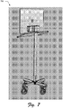
- Other examples are also contemplated, such as for attachment to a vertical surface (e.g., a cart or wall) as shown in the example 700 of FIG. 7 , for use in mobile or television implementations as further described in relation to FIG. QQ, and so forth.
- a computing device may be configured as a computer that is capable of communicating over the network, such as a desktop computer, a mobile station, an entertainment appliance, a set-top box communicatively coupled to a display device, a wireless phone, a game console, and so forth.
- the computing device 102 may range from full resource devices with substantial memory and processor resources (e.g., personal computers, game consoles) to a low-resource device with limited memory and/or processing resources (e.g., traditional set-top boxes, hand-held game consoles).
- the computing device 102 may be representative of a plurality of different devices, such as a remote control and set-top box combination, an image capture device and a game console configured to capture gestures, and so on.
- the computing device 102 includes a plurality of modular components 106 that may be physically and communicatively coupled, one to another, to provide interchangeability to access a variety of different functionality. Additionally, visual characteristics may be employed to indicate this different functionality, e.g., colors, graphics, and so on.
- FIG. 1 An example of a modular component 106 is a display modular component 108.
- the display modular component 108 includes a housing 110 having disposed therein one or more display hardware elements 112.
- the display hardware elements 112 include hardware elements configured to generate an output for display on a display device 114 of the display modular component 108.
- the display modular component 108 is communicatively and physically connected (e.g., rotationally) to a display device 114 via a hinge mechanism 116.
- the display device 114 may include a variety of functionality, such as to include touchscreen functionality to recognize gestures and other inputs. Rotation of the display device 114 in relation to the housing 110 of the display modular component 108 may be utilized to support a variety of different functionality, further discussion of which may be found in relation to FIG. 4 .
- the computing modular component 118 also includes a housing 120, separate from the housing 110 of the display modular component 108, which is physically and communicatively coupled to the display modular component 108.
- the computing modular component 118 is representative of functionality that may be added to the display modular component 108, which in this instance includes a processing system 122 and memory 124 as further described in relation to FIG. 2 .
- an accessory modular component 126 is an accessory modular component 126.
- the accessory modular component 126 includes a housing 128 and accessory hardware elements 130 disposed therein.
- the accessory modular component 126 may take a variety of configurations, so to can the accessory hardware elements 130.
- the accessory modular component 126 may be configured as an output device, such as speakers, a projector, and so on and as such the accessory hardware elements 130 may be configured to support this functionality.
- the accessory modular component 126 may also be configured as an input device, such as a natural user interface device as further described in relation to FIG. 3 .
- Other configurations are also contemplated, such as to include a battery that may be used to power the computing modular component 118 and/or the display modular component 108, a battery that may be charged by the computing device 102 for use with another computing device, and so on.
- the modular components 116 are illustrated as assuming a stacked configuration in which one modular component is stacked "on top" of another modular component when resting on a surface 104, attached vertically as shown in FIG. 7 , and so on.
- Other configurations are also contemplated without departing from the spirit and scope thereof.
- the physical and communicative coupling between the modular components 116 may be accomplished in a variety of ways.
- a magnetic coupling device may be included such that magnetism is utilized to form a physical connection between the components.
- the magnetic coupling device may include a flux fountain in which a plurality of magnets are arranged (e.g., perpendicular to each other) to steer a field of flux "outward" away from the components to increase a securing force than would otherwise be the case if the magnets were aligned such that the fields were also aligned, one to another.
- a flux fountain in which a plurality of magnets are arranged (e.g., perpendicular to each other) to steer a field of flux "outward" away from the components to increase a securing force than would otherwise be the case if the magnets were aligned such that the fields were also aligned, one to another.
- a protrusion 132 and cavity 134 arrangement may be utilized as illustrated.
- an axis corresponding to a height of the protrusion 132 defines a direction along which the modular components may be installed and removed, but causes mechanical binding in other directions to restrict removal in those directions.
- Other examples are also contemplated, such as mechanical latches and so on.
- FIG. 2 depicts an example implementation 200 showing different configurations of the computing device 102 of FIG. 1 through addition or removal of modular components from the device.
- This implementation 200 includes first, second, and third 202, 204, 206 examples of configurations of the computing device 102 of FIG. 1 .
- the display modular component 108 is illustrated as being used alone without additional modular components.
- the display modular component 108 include a power supply and may include one or more inputs that may be utilized with another device, such a HDMI, display ports, USB ports, and so on.
- the display modular component 108 may also include a sufficient amount of ballast to counteract a weight of the display device 114 such that component 108 may be placed on a surface 104 as shown in FIG. 1 without tipping over, e.g., which may be accomplished using speakers, lead weights, and so on.
- the display modular component 108 also includes functionality to execute an operating system, such as to be configured as a "thin” computing device to support a lightweight operating system, processor, and memory for mobile configurations. Addition of the computing modular component 118 may therefore be utilized to supplement this functionality in this example, such as to add processing, memory, and/or network resource functionality to support a "thick" or “rich” computing device configuration.
- an operating system such as to be configured as a "thin” computing device to support a lightweight operating system, processor, and memory for mobile configurations.
- Addition of the computing modular component 118 may therefore be utilized to supplement this functionality in this example, such as to add processing, memory, and/or network resource functionality to support a "thick" or “rich” computing device configuration.
- the computing modular component 118 is added to the display modular component 108 through stacking to form a physical and communicative coupling between the components 108, 118.
- functionality of the computing modular component 118 may be added to the display modular component 108 and vice versa.
- the computing modular component 118 may be utilized to generate a user interface for output by the display device 114 and the display modular component 108 may be utilized to provide power to the computing modular component 118.
- the accessory modular component 126 is added to the computing modular component 118 through stacking to form a physical and communicative coupling between the display, computing, and accessory components 108, 118, 126.
- the communicative and physical coupling may be formed between the accessory modular component 126 and the computing modular component 118 as previously described in relation to FIG. 1 , e.g., without the use of tools through protrusions, magnetism, mechanical connections (e.g., a slidable latch), and so forth.
- a variety of different functionality may be added, such as battery power, input devices, and/or output devices, a natural user interface input device, and so on as previously described.
- Other accessory configurations are also contemplated, an example of which is described in the following and shown in a corresponding figure.
- FIG. 3 depicts an example implementation 300 in which the computing device 102 of FIG. 1 also includes another accessory modular component 302.
- a housing 304 of an accessory modular component 302 is physically and communicatively coupled to the display device 114 of the display modular component 108, e.g., through use of protrusions, magnetisms, mechanical latches, and so forth. Placement of the accessory modular component 302 at this location may be utilized to support a variety of different functionality, such as any one of the accessory functionality previously described.
- the accessory is configured to support a natural user interface (NUI) input device 306 to support a natural user interface (NUI) that may recognize interactions that may not involve touch.
- NUI natural user interface
- the NUI input device 306 may be configured in a variety of ways to detect inputs without having a user touch a particular device, such as to recognize audio inputs through use of a microphone.
- the NUI input device 306 may be configured to support voice recognition to recognize particular utterances (e.g., a spoken command) as well as to recognize a particular user that provided the utterances.
- the NUI input device 306 that may be configured to support recognition of gestures, presented objects, images, and so on through use of a camera.
- the camera may be configured to include multiple lenses so that different perspectives may be captured and thus determine depth.
- the different perspectives may be used to determine a relative distance from the NUI input device 306 and thus a change in the relative distance.
- a time-of-flight camera may be utilized to determine relative distances of objects, e.g., arms, hands, fingers, legs, torso, and head of a user.
- the NUI input device 306 may capture images that are analyzed to recognize one or more motions made by a user, including what body part is used to make the motion as well as which user made the motion. Motions may be identified as gestures by the NUI input device 306 to initiate a corresponding functions.
- the NUI input device 306 may be leveraged to support depth perception in a variety of different ways.
- the images captured by the NUI input device 306 may be leveraged to provide a variety of other functionality, such as techniques to identify particular users (e.g., through facial recognition), objects, and so on.
- a variety of different types of gestures may be recognized, such a gestures that are recognized from a single type of input (e.g., a motion gesture) as well as gestures involving multiple types of inputs, e.g., a motion gesture and an object gesture made using an object such as a stylus.
- the NUI input device 306 may support a variety of different gesture techniques by recognizing and leveraging a division between inputs. It should be noted that by differentiating between inputs in the natural user interface (NUI), the number of gestures that are made possible by each of these inputs alone is also increased.
- the movements may be the same, different gestures (or different parameters to analogous commands) may be indicated using different types of inputs.
- the NUI input device 306 may support a natural user interface that supports a variety of user interaction's that do not involve touch. Although illustrated as attached to the display device 114 in this example, functionality of the NUI input device 306 may also be incorporated as part of the accessory modular component 126.
- the NUI input device 306 may be configured to support use in a variety of different configurations.
- a camera of the NUI input device 206 may be configured to capture images and communicate the images to the computing modular component 118 to recognize one or more gestures as previously described.
- the camera may be configured to rotate in cooperation with rotation of the display device 114 as shown in FIG. 4 . Further, this rotation may be performed automatically and without user intervention responsive to the rotation of the display device 114, e.g., through use of a motor.
- the rotation may be performed automatically and without user intervention such that a line-of-sight is maintained between a user of the computing device and the camera, e.g., through detection of a user's face and corresponding rotation of the camera to keep the user's face in view.
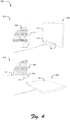
- FIG. 4 depicts an example implementation 400 in which movement of the display device in relation to the housing of the display modular component is shown.
- This implementation 400 is shown using first and second examples 402, 404.
- the display device 114 is illustrated as generally perpendicular to an axis of the housing 110 of the display modular component 108 that is defined as corresponding to a surface of the housing 110 to which other modular components and connected and/or to a surface on which the housing 110 is to be placed upon.
- this may be thought of as an "upright" configuration such that a user may view the display device 114 in a manner that mimics interaction with a desktop computer.
- the display device 114 is rotated using the hinge mechanism 116 to "lay flat" against the surface of the housing 110 of the display modular component 108 that defined the axis described above.
- This may be thought of as a "writing configuration" in which a user may interact with touchscreen functionality of the display device 114, e.g., via gestures, a stylus, and so on. In this way, a user may comfortably interact with the display device to perform handwriting, drawing, and so on.
- the hinge mechanism 116 may be configured in a variety of different ways.
- the hinge mechanism 116 may be configured to support approximately 180 degrees of rotation or more.
- the hinge mechanism 116 may be configured as a friction hinge such that a desired angle is maintained.
- the hinge may be configured as a split hinge mechanism 116 such that one part is connected to the housing 110 and another part is connected to the display device 114 such that a single joint is viewable by a user.
- the hinge mechanism 116 may be embedded in the housing 110 and even hidden inside the housing 110.
- the hinge mechanism 116 may be configured to permit the display device 114 to slide into position in addition to the rotation, e.g., permit slidable movement in relation to the housing 110.
- the display device 114 may include a hinge on the back to allow the display device 116 to slide forward when rotated to an angle that permits touch inputs to be provided in a more comfortable manner to a user.
- a hinge on the back to allow the display device 116 to slide forward when rotated to an angle that permits touch inputs to be provided in a more comfortable manner to a user.
- a variety of other examples are also contemplated without departing from the spirit and scope thereof.
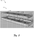
- FIGS. 5 and 6 depicts example implementations 500, 600 in which a modular component includes housing disposed therein that are swappable to add or remove corresponding functionality to the modular component.
- a housing 502 of a modular component 116 is shown, such as any one of the display, computing, or accessory modular components 108, 118, 126, 302 of FIGS. 1 and 3 .
- the housing 502 is configured to receive a plurality of other housings 504, 506, 508, 510 to be disposed therein such that different functionality may be "swapped" with the modular component and as such, not only is the modular component 116 itself interchangeable but so too is the functionality within the modular component 116.
- the housings 504-510 may correspond to memory, a wireless network functionality, a graphics processing unit, and a processing system. These housing 504-510 may be configured as pods that are placed within corresponding receptacles within the housing 502. Communicative and physical couplings may also be supported, e.g., through use of protrusions and cavities, mechanical attachment, magnetism (e.g., a flux fountain), and so forth. In this way, a user may simply remove and "drop in" a new one of the housings 504-510 to change functionality of the modular component 116.
- a common air conduit 512 may be utilized to facilitate heat management through the housings 502-510 as well as between modular components 116, e.g., the computing modular component may include a single fan that is utilized to cool other modular components 116.
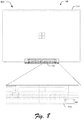
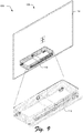
- FIG 8 depicts an example implementation 800 showing a rear view of the display modular component 108 of FIG. 1 along with an expanded view of the housing 110.
- FIG 9 depicts an example implementation 900 showing an isometric view of the display modular component 108 of FIG. 1 along with an expanded view of the housing 110.
- FIG 10 depicts an example implementation 1000 showing a side view of the display modular component 108 of FIG. 1 along with an expanded view of the housing 110.
- FIG 11 depicts an example implementation 1100 showing a top view of the display modular component 108 of FIG. 1 .
- FIG 12 depicts an example implementation 1200 showing a rear view of the housing 110 of the display modular component 108 of FIG. 1 .
- FIG 13 depicts an example implementation 1300 showing an isometric view of the computing modular component 118 of FIG. 1 .
- FIG 14 depicts an example implementation 1400 showing a side view of the computing modular component 118 of FIG. 1 .
- FIG 15 depicts an example implementation 1500 showing a top view of the computing modular component 118 of FIG. 1 .
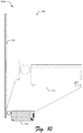
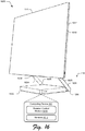
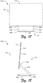
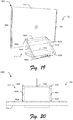
- FIGS. 16-21 depict additional example implementations 1600, 1700, 1800, 1900, 2000, 2100 of the computing device 102.
- the computing device 102 in this example includes a base 1602, which may be modular as further described below.
- the computing device 102 is connected to the base 1602 using a hinge mechanism 116.
- the hinge mechanism 116 includes a plurality of members 1604.
- First rotational devices 1606 are used to connect the members 1604 of the hinge mechanism 116 to the base 1602 and second rotational devices 1608 are used to connect the members 1604 of the hinge mechanism 116 to the display device 114.
- the first and second rotational devices 1606, 1608 are configurable in a variety of ways.
- clutches e.g., electromagnetic, mechanical, and so on
- the rotation control module 1610 is configured to leverage sensors 1612 to detect when to engage and disengage the clutches.
- FIG. 21 depicts an example implementation 2100 in which the display device 114 is positioned in relation to the base 1602 using first and second stages 2102, 2104.
- the sensors 1612 may include touchscreen sensors configured as part of the display device, at a side 1614 of a housing of the display device 114, at a rear 1616 that is disposed on an opposing side to that of a display of the display device 114, and so forth.
- An output of the sensors 1616, when processed by the rotation control module 1610 is usable to detect when to permit rotation of the first and second rotation devices 1606, 1608.
- the rotation control module 1610 may detect that the display device 114 is being grasped by a hand of a user, and in response disengage the first and second rotation devices 1606, 1608, allowing the display device 114 to be positioned as desired in relation to the base 1602 as described by a user.
- the user may release the grip, which is detected by the rotational control module 1610 using the sensors 1612 and in response causes clutches of the first and second rotation devices 1606, 1608 to re-engage.
- the display device 114 may be efficiently positioned by a single hand of a user as desired, even in instances where the display device 114 has a relatively large size, e.g., 24 inches and larger.
- the rotation control module 1610 may be configured to protect the computing device, such as to permit or prevent certain configurations to avoid configurations in which the display device 114 makes contact with the base 1602, is off-balance, restricts a lower edge of the display device 114 from making contact with a surface on which the base 1602 rests, and so forth.
- the display device 114 includes a "glass to the edge" configuration in which the display reaches to an edge between a front and side surfaces.
- the display device 114 has a thickness of less than nine millimeters (e.g., 8.5 millimeters), and includes microphones, a three-dimensional camera as part of the display, speakers and a rubber bumper along the bottom, removable storage (e.g., SD) and a USB connection along the side.
- FIG. 19 depicts a rear of the computing device 102.
- a connection portion 1902 is shown that support a connection between the hinge mechanism 116 and the display device 114.
- the display device 114 has a curved rear housing, which provides stiffness and torsional rigidity across the surface of the display of the display device 114.
- Backlight LEDs or other light output devices 1904 are included at the sides that may be used to provide a complementary light output to which is displayed by the display device 114.
- connection portion 1902 in this example has a wedge shape, which may be used to housing hardware components of the computing device 102.
- the connection portion 1902 is permanently fixed to the display device 114.
- the connection portion 1902 is removable such that the display device 102 is separable from the connection portion 1902.
- the display device 102 may be configured as a tablet computer that is removably connected to the connection portion 1902 and thus the base 1602 of the computing device 102.
- the rotational control module 1610 may be configured to detect that a user has grasped the display device 114 via a single hand and thus permit rotation and when grasped by two hands cause separation of the connection portion and the display device 114.
- the rotational control module 1610 may be configured to detect that a user has grasped the display device 114 using two fingers and thus permit rotation and when grasped by more than two fingers cause separation of the connection portion and the display device 114
- the base 1602 may include hardware components to complement tablet functionality of the display device 114, such as additional hardware, data storage, and/or network connectivity.
- the display device 114 may be communicatively coupled to the base 1602 in a variety of ways, such as a wired connection through the members 1604, a wireless connection, and so forth.
- the computing device 102 may include a variety of other features.
- a keyboard may be included on a surface of the base 1602.
- a projector may be included on the display device 114 and/or base to project an image of a keyboard with which user interaction is detected through use of a three-dimensional camera.
- the base 1602 may also include stepped edges to support the modular configuration previously described as well as a thermal system, such as to draw in air from a front and exhaust through the sides and back.
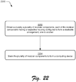
- FIG. 22 is a flow diagram depicting a procedure in an example implementation in which the modular computing device of FIG. 1 is assembled through stacking.
- a plurality a plurality of modular components 116 are obtained, each of the modular components having a respective housing configured to form a stackable arrangement, one to another (block 2202).
- the plurality of modular components 116 are stacked to form a computing device 102 (block 2204).
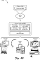
- FIG. 23 illustrates an example system generally at 2300 that includes an example computing device 2302 that is representative of one or more computing systems and/or devices that may implement the various techniques described herein.
- the computing device 2302 may be, for example, a server of a service provider, a device associated with a client (e.g., a client device), an on-chip system, and/or any other suitable computing device or computing system.
- the example computing device 2302 as illustrated includes a processing system 2304, one or more computer-readable media 2306, and one or more I/O interface 2308 that are communicatively coupled, one to another.
- the computing device 2302 may further include a system bus or other data and command transfer system that couples the various components, one to another.
- a system bus can include any one or combination of different bus structures, such as a memory bus or memory controller, a peripheral bus, a universal serial bus, and/or a processor or local bus that utilizes any of a variety of bus architectures.
- a variety of other examples are also contemplated, such as control and data lines.
- the processing system 2304 is representative of functionality to perform one or more operations using hardware. Accordingly, the processing system 2304 is illustrated as including hardware element 2310 that may be configured as processors, functional blocks, and so forth. This may include implementation in hardware as an application specific integrated circuit or other logic device formed using one or more semiconductors.
- the hardware elements 2310 are not limited by the materials from which they are formed or the processing mechanisms employed therein.
- processors may be comprised of semiconductors) and/or transistors (e.g., electronic integrated circuits (ICs)).
- processor-executable instructions may be electronically-executable instructions.
- the computer-readable storage media 2306 is illustrated as including memory/storage 2312.
- the memory/storage 2312 represents memory/storage capacity associated with one or more computer-readable media.
- the memory/storage component 2312 may include volatile media (such as random access memory (RAM)) and/or nonvolatile media (such as read only memory (ROM), Flash memory, optical disks, magnetic disks, and so forth).
- the memory/storage component 2312 may include fixed media (e.g., RAM, ROM, a fixed hard drive, and so on) as well as removable media (e.g., Flash memory, a removable hard drive, an optical disc, and so forth).
- the computer-readable media 2306 may be configured in a variety of other ways as further described below.
- Input/output interface(s) 2308 are representative of functionality to allow a user to enter commands and information to computing device 2302, and also allow information to be presented to the user and/or other components or devices using various input/output devices.
- input devices include a keyboard, a cursor control device (e.g., a mouse), a microphone, a scanner, touch functionality (e.g., capacitive or other sensors that are configured to detect physical touch), a camera (e.g., which may employ visible or non-visible wavelengths such as infrared frequencies to recognize movement as gestures that do not involve touch), and so forth.
- Examples of output devices include a display device (e.g., a monitor or projector), speakers, a printer, a network card, tactile-response device, and so forth.
- the computing device 2302 may be configured in a variety of ways as further described below to support user interaction.
- modules include routines, programs, objects, elements, components, data structures, and so forth that perform particular tasks or implement particular abstract data types.
- module generally represent software, firmware, hardware, or a combination thereof.
- the features of the techniques described herein are platform-independent, meaning that the techniques may be implemented on a variety of commercial computing platforms having a variety of processors.
- Computer-readable media may include a variety of media that may be accessed by the computing device 2302.
- computer-readable media may include "computer-readable storage media” and "computer-readable signal media.”
- Computer-readable storage media may refer to media and/or devices that enable persistent and/or non-transitory storage of information in contrast to mere signal transmission, carrier waves, or signals per se. Thus, computer-readable storage media refers to non-signal bearing media.
- the computer-readable storage media includes hardware such as volatile and non-volatile, removable and non-removable media and/or storage devices implemented in a method or technology suitable for storage of information such as computer readable instructions, data structures, program modules, logic elements/circuits, or other data.
- Examples of computer-readable storage media may include, but are not limited to, RAM, ROM, EEPROM, flash memory or other memory technology, CD-ROM, digital versatile disks (DVD) or other optical storage, hard disks, magnetic cassettes, magnetic tape, magnetic disk storage or other magnetic storage devices, or other storage device, tangible media, or article of manufacture suitable to store the desired information and which may be accessed by a computer.
- Computer-readable signal media may refer to a signal-bearing medium that is configured to transmit instructions to the hardware of the computing device 2302, such as via a network.
- Signal media typically may embody computer readable instructions, data structures, program modules, or other data in a modulated data signal, such as carrier waves, data signals, or other transport mechanism.
- Signal media also include any information delivery media.
- modulated data signal means a signal that has one or more of its characteristics set or changed in such a manner as to encode information in the signal.
- communication media include wired media such as a wired network or direct-wired connection, and wireless media such as acoustic, RF, infrared, and other wireless media.
- hardware elements 2310 and computer-readable media 2306 are representative of modules, programmable device logic and/or fixed device logic implemented in a hardware form that may be employed in some embodiments to implement at least some aspects of the techniques described herein, such as to perform one or more instructions.
- Hardware may include components of an integrated circuit or on-chip system, an application-specific integrated circuit (ASIC), a field-programmable gate array (FPGA), a complex programmable logic device (CPLD), and other implementations in silicon or other hardware.
- ASIC application-specific integrated circuit
- FPGA field-programmable gate array
- CPLD complex programmable logic device
- hardware may operate as a processing device that performs program tasks defined by instructions and/or logic embodied by the hardware as well as a hardware utilized to store instructions for execution, e.g., the computer-readable storage media described previously.
- software, hardware, or executable modules may be implemented as one or more instructions and/or logic embodied on some form of computer-readable storage media and/or by one or more hardware elements 2310.
- the computing device 2302 may be configured to implement particular instructions and/or functions corresponding to the software and/or hardware modules. Accordingly, implementation of a module that is executable by the computing device 2302 as software may be achieved at least partially in hardware, e.g., through use of computer-readable storage media and/or hardware elements 2310 of the processing system 2304.
- the instructions and/or functions may be executable/operable by one or more articles of manufacture (for example, one or more computing devices 2302 and/or processing systems 2304) to implement techniques, modules, and examples described herein.
- the example system 2300 enables ubiquitous environments for a seamless user experience when running applications on a personal computer (PC), a television device, and/or a mobile device. Services and applications run substantially similar in all three environments for a common user experience when transitioning from one device to the next while utilizing an application, playing a video game, watching a video, and so on.
- PC personal computer
- TV device a television device
- mobile device a mobile device. Services and applications run substantially similar in all three environments for a common user experience when transitioning from one device to the next while utilizing an application, playing a video game, watching a video, and so on.
- multiple devices are interconnected through a central computing device.
- the central computing device may be local to the multiple devices or may be located remotely from the multiple devices.
- the central computing device may be a cloud of one or more server computers that are connected to the multiple devices through a network, the Internet, or other data communication link.
- this interconnection architecture enables functionality to be delivered across multiple devices to provide a common and seamless experience to a user of the multiple devices.
- Each of the multiple devices may have different physical requirements and capabilities, and the central computing device uses a platform to enable the delivery of an experience to the device that is both tailored to the device and yet common to all devices.
- a class of target devices is created and experiences are tailored to the generic class of devices.
- a class of devices may be defined by physical features, types of usage, or other common characteristics of the devices.
- the computing device 2302 may assume a variety of different configurations, such as for computer 2314, mobile 2316, and television 2318 uses. Each of these configurations includes devices that may have generally different constructs and capabilities, and thus the computing device 2302 may be configured according to one or more of the different device classes. For instance, the computing device 2302 may be implemented as the computer 2314 class of a device that includes a personal computer, desktop computer, a multi-screen computer, laptop computer, netbook, and so on.
- the computing device 2302 may also be implemented as the mobile 2316 class of device that includes mobile devices, such as a mobile phone, portable music player, portable gaming device, a tablet computer, a multi-screen computer, and so on.
- the computing device 2302 may also be implemented as the television 2318 class of device that includes devices having or connected to generally larger screens in casual viewing environments. These devices include televisions, set-top boxes, gaming consoles, and so on.
- the techniques described herein may be supported by these various configurations of the computing device 2302 and are not limited to the specific examples of the techniques described herein. This functionality may also be implemented all or in part through use of a distributed system, such as over a "cloud" 2320 via a platform 2322 as described below.
- the cloud 2320 includes and/or is representative of a platform 2322 for resources 2324.
- the platform 2322 abstracts underlying functionality of hardware (e.g., servers) and software resources of the cloud 2320.
- the resources 2324 may include applications and/or data that can be utilized while computer processing is executed on servers that are remote from the computing device 2302.
- Resources 2324 can also include services provided over the Internet and/or through a subscriber network, such as a cellular or Wi-Fi network.
- the platform 2322 may abstract resources and functions to connect the computing device 2302 with other computing devices.
- the platform 2322 may also serve to abstract scaling of resources to provide a corresponding level of scale to encountered demand for the resources 2324 that are implemented via the platform 2322.
- implementation of functionality described herein may be distributed throughout the system 2300.
- the functionality may be implemented in part on the computing device 2302 as well as via the platform 2322 that abstracts the functionality of the cloud 2320.
Landscapes
- Engineering & Computer Science (AREA)
- Theoretical Computer Science (AREA)
- Computer Hardware Design (AREA)
- General Engineering & Computer Science (AREA)
- Physics & Mathematics (AREA)
- General Physics & Mathematics (AREA)
- Human Computer Interaction (AREA)
- Microelectronics & Electronic Packaging (AREA)
- Multimedia (AREA)
- Mathematical Physics (AREA)
- User Interface Of Digital Computer (AREA)
- Casings For Electric Apparatus (AREA)
- Calculators And Similar Devices (AREA)
Description
- The range and functionality of hardware resources that are made available for use with a computing device is ever increasing. For example, faster processors, memories that support larger storage amounts, wireless communication devices that support increased bandwidth, and so on are being continually developed.
- However, conventional techniques that made this increased functionality available to a user generally involved the replacement of a user's current device with a new device having this functionality. Thus, these conventional techniques can be expensive and thus avoided by a user, thereby limiting a device maker's opportunity to provide this increased functionality to users.
-
US 6,118,663 shows a multi-configuration modular computer that can be configured to be different types of personal computers or associated computer devices. The multi-configuration modular computer comprises a display module, a keyboard and pointer device module, a motherboard and power module, and an expansion module. By selecting and combining different modules, the multi-configuration modular computer can be configured to be a LCD display monitor, a pen-based computer, a terminal, a network personal computer, a sub-notebook computer, a notebook computer or a desktop computer. -
US 2013/0242495 A1 relates to a connection device for computing devices. The connection device comprises a plurality of connection portions that are physically and communicatively coupled, one to another. Each of the plurality of connection portions has at least one communication contact configured to form a communicative coupling with a respective one of a plurality of computing devices and with at least one other communication contact of another one of the connections portions to support communication between the plurality of computing devices. Each of the plurality of connection portions also includes a magnetic coupling device to form a removable magnetic attachment to the respective one of the plurality of computing devices. -
WO 2011/093951 A1 relates to an apparatus for transforming a consumer device enclosure. The apparatus enables modular units to be attached to increase capacity without compromising the integrity of the overall structure. -
EP 0 132 152 A2 discloses another computer system made up of a plurality of three or more modules which are arranged horizontally in a row, side-by-side. Each module includes a rectangular box shaped chassis containing a part of the computer system. -
US 2007/0208892 A1 discloses a computing system that includes a plurality of interconnected components. The components include a processing subsystem, an input subsystem, an output subsystem, a storage subsystem, and a power subsystem. Subsets of the plurality of components may be rearranged and interconnected in various configurations to form different computing systems. -
US 2008/0172831 A1 describes a hinge module. A T-shaped frame is pivotally connected with a base portion at one end such that the T-shaped frame rotates around a first axis relative to the base portion. A pair of connection members are pivotally connected with the other two opposite ends of the T-shaped frame such that the pair of connection members rotates around a second axis relative to the T-shaped frame, wherein the second axis is perpendicular to the first axis, and led through a cavity of the T-shaped frame. A U-shaped casing is manual-detachably connected with the T-shaped frame to fully cover a cavity of the T-shaped frame. -
US 2006/0105623 A1 describes a connection apparatus for transmitting power and signals for a notebook PC. The power and signal connection apparatus includes a hinge and an arc-shaped connector. The hinge interconnects a battery module, a display panel and a base unit of the notebook PC. When the display panel is opened, the base unit is lifted at the hinge side by the battery module. The arc-shaped connector maintains an electrical connection between the battery and a motherboard of the notebook PC. - The invention relates to modular computing device techniques and is defined by
independent claim 1. Advantageous embodiments of the invention are subject to the dependent claims. - According to the invention, a computing device includes a display modular component including a housing, a display device physically and communicatively coupled to the housing via a hinge, and one or more display hardware elements disposed within the housing that are configured to output a display for display by the display device. The computing device also includes a computing modular component including a housing that is physically and communicatively coupled to the display modular component, a processing system disposed within the housing, and memory disposed within the housing. The processing system is configured to execute instructions stored by the processing system to generate a user interface for display by the display device of the display modular component.
- According to the invention, a display modular component includes a housing, a display device physically and communicatively coupled to the housing via a hinge, and one or more display hardware elements disposed within the housing and configured to output a display for display by the display device. The housing is configured to form a communicative and removable physical coupling to a plurality of other housings having hardware elements disposed therein that are configured to support functionality relating to the display.
- In one or more implementations, a system includes a plurality of modular components, each of the modular components having a respective housing configured to form a stackable arrangement, one to another, and configured to be physically and communicative coupled to form a computing device.
- In one or more implementations, a plurality of modular components are obtained, each of the modular components having a respective housing configured to form a stackable arrangement, one to another. The plurality of modular components are stacked to form a computing device.
- The detailed description is described with reference to the accompanying figures. In the figures, the left-most digit(s) of a reference number identifies the figure in which the reference number first appears. The use of the same reference numbers in different instances in the description and the figures may indicate similar or identical items. Entities represented in the figures may be indicative of one or more entities and thus reference may be made interchangeably to single or plural forms of the entities in the discussion.
-
FIG. 1 is an illustration of an environment in an example implementation that is operable to employ the modular computing device techniques described herein. -
FIG. 2 depicts an example implementation showing different configurations of a computing device ofFIG. 1 through addition or removal of modular components to or from the device. -
FIG. 3 depicts an example implementation in which a computing device ofFIG. 1 also includes another accessory modular component. -
FIG. 4 depicts an example implementation in which movement of a display device in relation to a housing of a display modular component is shown. -
FIGS. 5 and6 depicts example implementations in which a modular component ofFIG. 1 includes housing disposed therein that are swappable to add or remove corresponding functionality to the modular component. -
FIG. 7 depicts an example implementation showing the computing device ofFIG. 1 as mounted to a vertical surface, which is part of a cart in this example. -
FIG 8 depicts an example implementation showing a rear view of the display modular component ofFIG. 1 along with an expanded view of the housing. -
FIG 9 depicts an example implementation showing an isometric view of the display modular component ofFIG. 1 along with an expanded view of the housing. -
FIG 10 depicts an example implementation showing a side view of the display modular component ofFIG. 1 along with an expanded view of the housing. -
FIG 11 depicts an example implementation showing a top view of the display modular component ofFIG. 1 . -
FIG 12 depicts an example implementation showing a rear view of the housing of the display modular component ofFIG. 1 . -
FIG 13 depicts an example implementation showing an isometric view of the computing modular component ofFIG. 1 . -
FIG 14 depicts an example implementation showing a side view of the computing modular component ofFIG. 1 . -
FIG 15 depicts an example implementation showing a top view of the computing modular component ofFIG. 1 . -
FIGS. 16-21 depict additional example implementations of the computing device. -
FIG. 22 is a flow diagram depicting a procedure in an example implementation in which the modular computing device ofFIG. 1 is assembled through stacking. -
FIG. 23 illustrates an example system including various components of an example device that can be implemented as any type of computing device as described with reference toFIGS. 1-16 to implement embodiments of the techniques described herein. - The rate at which an ever increasing functionality variety of functionality is made available to computing devices continues to increase. However, conventional techniques utilized to make this functionality available to users have typically relied on replacement of the computing device as a whole, which could be expensive and thus limit access of users to this ever increasing functionality.
- Modular computing device techniques are described. In one or more implementations, a computing device is assembled from a plurality of modular components formed using respective housings that may be physically and communicatively coupled, one to another, without the use of tools to add desired functionality. For example, a display modular component may include a housing, a display device, and a power supply configured to power the display. A computing modular component may be attached to the display modular component to add processing and memory functionality, as well as receive power from the display modular component. Accessory modular components may also be attached, such as to support input via a natural user interface, add speakers, a battery, and so on.
- Additionally, these modular components may also formed using modules themselves. For example, a computing modular component may include a housing having a processing system, another housing having a memory system, yet another housing having a wireless communication device, and so on. These housings may be configured to be "swappable" within the housing to change functionality as desired, such as to update the processing, memory, and/or network resources of the computing device. In this way, the computing device may be altered and changed readily by a user in an intuitive manner without requiring detailed knowledge of the hardware, further discussion of which may be found in relation to the following sections.
- In the following discussion, an example environment is first described that may employ the modular computing device techniques described herein. Functionality, features, and concepts described in relation to the examples in the following section may be employed in the context of the procedures described herein. Further, functionality, features, and concepts described in relation to different procedures below may be interchanged among the different procedures and are not limited to implementation in the context of an individual procedure. Moreover, blocks associated with different representative procedures and corresponding figures herein may be applied together and/or combined in different ways. Thus, individual functionality, features, and concepts described in relation to different example environments, devices, components, and procedures herein may be used in any suitable combinations and are not limited to the particular combinations represented by the enumerated examples.
-
FIG. 1 is an illustration of anenvironment 100 in an example implementation that is operable to employ techniques described herein. The illustratedenvironment 100 includes acomputing device 102 having a modular configuration. Thecomputing device 102 may assume a variety of configurations. - As illustrated, for instance, the
computing device 102 assumes a "desktop" configuration in which the computing device is configured to be placed on asurface 104. Other examples are also contemplated, such as for attachment to a vertical surface (e.g., a cart or wall) as shown in the example 700 ofFIG. 7 , for use in mobile or television implementations as further described in relation to FIG. QQ, and so forth. - For example, a computing device may be configured as a computer that is capable of communicating over the network, such as a desktop computer, a mobile station, an entertainment appliance, a set-top box communicatively coupled to a display device, a wireless phone, a game console, and so forth. Thus, the
computing device 102 may range from full resource devices with substantial memory and processor resources (e.g., personal computers, game consoles) to a low-resource device with limited memory and/or processing resources (e.g., traditional set-top boxes, hand-held game consoles). Additionally, although asingle computing device 102 is shown, thecomputing device 102 may be representative of a plurality of different devices, such as a remote control and set-top box combination, an image capture device and a game console configured to capture gestures, and so on. - The
computing device 102 includes a plurality ofmodular components 106 that may be physically and communicatively coupled, one to another, to provide interchangeability to access a variety of different functionality. Additionally, visual characteristics may be employed to indicate this different functionality, e.g., colors, graphics, and so on. - An example of a
modular component 106 is a displaymodular component 108. The displaymodular component 108 includes ahousing 110 having disposed therein one or more display hardware elements 112. The display hardware elements 112 include hardware elements configured to generate an output for display on adisplay device 114 of the displaymodular component 108. - The display
modular component 108 is communicatively and physically connected (e.g., rotationally) to adisplay device 114 via ahinge mechanism 116. Thedisplay device 114 may include a variety of functionality, such as to include touchscreen functionality to recognize gestures and other inputs. Rotation of thedisplay device 114 in relation to thehousing 110 of the displaymodular component 108 may be utilized to support a variety of different functionality, further discussion of which may be found in relation toFIG. 4 . - Another example of a
modular component 116 of thecomputing device 102 is illustrated as a computingmodular component 118. The computingmodular component 118 also includes ahousing 120, separate from thehousing 110 of the displaymodular component 108, which is physically and communicatively coupled to the displaymodular component 108. The computingmodular component 118 is representative of functionality that may be added to the displaymodular component 108, which in this instance includes aprocessing system 122 andmemory 124 as further described in relation toFIG. 2 . - Yet another example of a
modular component 106 of thecomputing device 102 is an accessorymodular component 126. Like above, the accessorymodular component 126 includes a housing 128 and accessory hardware elements 130 disposed therein. As the accessorymodular component 126 may take a variety of configurations, so to can the accessory hardware elements 130. - For example, the accessory
modular component 126 may be configured as an output device, such as speakers, a projector, and so on and as such the accessory hardware elements 130 may be configured to support this functionality. The accessorymodular component 126 may also be configured as an input device, such as a natural user interface device as further described in relation toFIG. 3 . Other configurations are also contemplated, such as to include a battery that may be used to power the computingmodular component 118 and/or the displaymodular component 108, a battery that may be charged by thecomputing device 102 for use with another computing device, and so on. - In the illustrated example, the
modular components 116 are illustrated as assuming a stacked configuration in which one modular component is stacked "on top" of another modular component when resting on asurface 104, attached vertically as shown inFIG. 7 , and so on. Other configurations are also contemplated without departing from the spirit and scope thereof. The physical and communicative coupling between themodular components 116 may be accomplished in a variety of ways. For example, a magnetic coupling device may be included such that magnetism is utilized to form a physical connection between the components. The magnetic coupling device, for instance, may include a flux fountain in which a plurality of magnets are arranged (e.g., perpendicular to each other) to steer a field of flux "outward" away from the components to increase a securing force than would otherwise be the case if the magnets were aligned such that the fields were also aligned, one to another. - In another example, a
protrusion 132 andcavity 134 arrangement may be utilized as illustrated. In the illustrated example, an axis corresponding to a height of theprotrusion 132 defines a direction along which the modular components may be installed and removed, but causes mechanical binding in other directions to restrict removal in those directions. Other examples are also contemplated, such as mechanical latches and so on. In this way, a user may readily add, remove, and replace modular components from thecomputing device 102 to configure thecomputing device 102 to include desired functionality, further discussion of which may be found in relation to the following description and shown in a corresponding figure. -
FIG. 2 depicts anexample implementation 200 showing different configurations of thecomputing device 102 ofFIG. 1 through addition or removal of modular components from the device. Thisimplementation 200 includes first, second, and third 202, 204, 206 examples of configurations of thecomputing device 102 ofFIG. 1 . - In the first example 202, the display
modular component 108 is illustrated as being used alone without additional modular components. As illustrated, the displaymodular component 108 include a power supply and may include one or more inputs that may be utilized with another device, such a HDMI, display ports, USB ports, and so on. The displaymodular component 108 may also include a sufficient amount of ballast to counteract a weight of thedisplay device 114 such thatcomponent 108 may be placed on asurface 104 as shown inFIG. 1 without tipping over, e.g., which may be accomplished using speakers, lead weights, and so on. - In one or more implementations, the display
modular component 108 also includes functionality to execute an operating system, such as to be configured as a "thin" computing device to support a lightweight operating system, processor, and memory for mobile configurations. Addition of the computingmodular component 118 may therefore be utilized to supplement this functionality in this example, such as to add processing, memory, and/or network resource functionality to support a "thick" or "rich" computing device configuration. - In the second example 204, the computing
modular component 118 is added to the displaymodular component 108 through stacking to form a physical and communicative coupling between thecomponents modular component 118 may be added to the displaymodular component 108 and vice versa. For instance, the computingmodular component 118 may be utilized to generate a user interface for output by thedisplay device 114 and the displaymodular component 108 may be utilized to provide power to the computingmodular component 118. - In the third example 206, the accessory
modular component 126 is added to the computingmodular component 118 through stacking to form a physical and communicative coupling between the display, computing, andaccessory components modular component 126 and the computingmodular component 118 as previously described in relation toFIG. 1 , e.g., without the use of tools through protrusions, magnetism, mechanical connections (e.g., a slidable latch), and so forth. A variety of different functionality may be added, such as battery power, input devices, and/or output devices, a natural user interface input device, and so on as previously described. Other accessory configurations are also contemplated, an example of which is described in the following and shown in a corresponding figure. -
FIG. 3 depicts anexample implementation 300 in which thecomputing device 102 ofFIG. 1 also includes another accessory modular component 302. In this example, a housing 304 of an accessory modular component 302 is physically and communicatively coupled to thedisplay device 114 of the displaymodular component 108, e.g., through use of protrusions, magnetisms, mechanical latches, and so forth. Placement of the accessory modular component 302 at this location may be utilized to support a variety of different functionality, such as any one of the accessory functionality previously described. - In the illustrated example, the accessory is configured to support a natural user interface (NUI)
input device 306 to support a natural user interface (NUI) that may recognize interactions that may not involve touch. For example, theNUI input device 306 may be configured in a variety of ways to detect inputs without having a user touch a particular device, such as to recognize audio inputs through use of a microphone. For instance, theNUI input device 306 may be configured to support voice recognition to recognize particular utterances (e.g., a spoken command) as well as to recognize a particular user that provided the utterances. - In another example, the
NUI input device 306 that may be configured to support recognition of gestures, presented objects, images, and so on through use of a camera. The camera, for instance, may be configured to include multiple lenses so that different perspectives may be captured and thus determine depth. The different perspectives, for instance, may be used to determine a relative distance from theNUI input device 306 and thus a change in the relative distance. - In another example, a time-of-flight camera may be utilized to determine relative distances of objects, e.g., arms, hands, fingers, legs, torso, and head of a user. For instance, the
NUI input device 306 may capture images that are analyzed to recognize one or more motions made by a user, including what body part is used to make the motion as well as which user made the motion. Motions may be identified as gestures by theNUI input device 306 to initiate a corresponding functions. Thus, theNUI input device 306 may be leveraged to support depth perception in a variety of different ways. The images captured by theNUI input device 306 may be leveraged to provide a variety of other functionality, such as techniques to identify particular users (e.g., through facial recognition), objects, and so on. - A variety of different types of gestures may be recognized, such a gestures that are recognized from a single type of input (e.g., a motion gesture) as well as gestures involving multiple types of inputs, e.g., a motion gesture and an object gesture made using an object such as a stylus. Thus, the
NUI input device 306 may support a variety of different gesture techniques by recognizing and leveraging a division between inputs. It should be noted that by differentiating between inputs in the natural user interface (NUI), the number of gestures that are made possible by each of these inputs alone is also increased. - For example, although the movements may be the same, different gestures (or different parameters to analogous commands) may be indicated using different types of inputs. Thus, the
NUI input device 306 may support a natural user interface that supports a variety of user interaction's that do not involve touch. Although illustrated as attached to thedisplay device 114 in this example, functionality of theNUI input device 306 may also be incorporated as part of the accessorymodular component 126. - The
NUI input device 306 may be configured to support use in a variety of different configurations. For example, a camera of theNUI input device 206 may be configured to capture images and communicate the images to the computingmodular component 118 to recognize one or more gestures as previously described. The camera may be configured to rotate in cooperation with rotation of thedisplay device 114 as shown inFIG. 4 . Further, this rotation may be performed automatically and without user intervention responsive to the rotation of thedisplay device 114, e.g., through use of a motor. For example, the rotation may be performed automatically and without user intervention such that a line-of-sight is maintained between a user of the computing device and the camera, e.g., through detection of a user's face and corresponding rotation of the camera to keep the user's face in view. -
FIG. 4 depicts anexample implementation 400 in which movement of the display device in relation to the housing of the display modular component is shown. Thisimplementation 400 is shown using first and second examples 402, 404. In the first example 402, thedisplay device 114 is illustrated as generally perpendicular to an axis of thehousing 110 of the displaymodular component 108 that is defined as corresponding to a surface of thehousing 110 to which other modular components and connected and/or to a surface on which thehousing 110 is to be placed upon. Thus, this may be thought of as an "upright" configuration such that a user may view thedisplay device 114 in a manner that mimics interaction with a desktop computer. - In the second example 404, the
display device 114 is rotated using thehinge mechanism 116 to "lay flat" against the surface of thehousing 110 of the displaymodular component 108 that defined the axis described above. This may be thought of as a "writing configuration" in which a user may interact with touchscreen functionality of thedisplay device 114, e.g., via gestures, a stylus, and so on. In this way, a user may comfortably interact with the display device to perform handwriting, drawing, and so on. - The
hinge mechanism 116 may be configured in a variety of different ways. For example, thehinge mechanism 116 may be configured to support approximately 180 degrees of rotation or more. Thehinge mechanism 116 may be configured as a friction hinge such that a desired angle is maintained. Additionally, the hinge may be configured as asplit hinge mechanism 116 such that one part is connected to thehousing 110 and another part is connected to thedisplay device 114 such that a single joint is viewable by a user. Further, thehinge mechanism 116 may be embedded in thehousing 110 and even hidden inside thehousing 110. In one or more implementations, thehinge mechanism 116 may be configured to permit thedisplay device 114 to slide into position in addition to the rotation, e.g., permit slidable movement in relation to thehousing 110. For instance, thedisplay device 114 may include a hinge on the back to allow thedisplay device 116 to slide forward when rotated to an angle that permits touch inputs to be provided in a more comfortable manner to a user. A variety of other examples are also contemplated without departing from the spirit and scope thereof. -
FIGS. 5 and6 depictsexample implementations housing 502 of amodular component 116 is shown, such as any one of the display, computing, or accessorymodular components FIGS. 1 and3 . Thehousing 502 is configured to receive a plurality ofother housings modular component 116 itself interchangeable but so too is the functionality within themodular component 116. - In a computing modular component example 118, for instance, the housings 504-510 may correspond to memory, a wireless network functionality, a graphics processing unit, and a processing system. These housing 504-510 may be configured as pods that are placed within corresponding receptacles within the
housing 502. Communicative and physical couplings may also be supported, e.g., through use of protrusions and cavities, mechanical attachment, magnetism (e.g., a flux fountain), and so forth. In this way, a user may simply remove and "drop in" a new one of the housings 504-510 to change functionality of themodular component 116. Acommon air conduit 512 may be utilized to facilitate heat management through the housings 502-510 as well as betweenmodular components 116, e.g., the computing modular component may include a single fan that is utilized to cool othermodular components 116. -
FIG 8 depicts anexample implementation 800 showing a rear view of the displaymodular component 108 ofFIG. 1 along with an expanded view of thehousing 110. -
FIG 9 depicts anexample implementation 900 showing an isometric view of the displaymodular component 108 ofFIG. 1 along with an expanded view of thehousing 110. -
FIG 10 depicts anexample implementation 1000 showing a side view of the displaymodular component 108 ofFIG. 1 along with an expanded view of thehousing 110. -
FIG 11 depicts anexample implementation 1100 showing a top view of the displaymodular component 108 ofFIG. 1 . -
FIG 12 depicts anexample implementation 1200 showing a rear view of thehousing 110 of the displaymodular component 108 ofFIG. 1 . -
FIG 13 depicts anexample implementation 1300 showing an isometric view of the computingmodular component 118 ofFIG. 1 . -
FIG 14 depicts anexample implementation 1400 showing a side view of the computingmodular component 118 ofFIG. 1 . -
FIG 15 depicts anexample implementation 1500 showing a top view of the computingmodular component 118 ofFIG. 1 . -
FIGS. 16-21 depictadditional example implementations computing device 102. Thecomputing device 102 in this example includes abase 1602, which may be modular as further described below. - The
computing device 102 is connected to thebase 1602 using ahinge mechanism 116. In this example, thehinge mechanism 116 includes a plurality ofmembers 1604. Firstrotational devices 1606 are used to connect themembers 1604 of thehinge mechanism 116 to thebase 1602 and secondrotational devices 1608 are used to connect themembers 1604 of thehinge mechanism 116 to thedisplay device 114. - The first and second
rotational devices rotation control module 1610. Therotation control module 1610 is configured to leveragesensors 1612 to detect when to engage and disengage the clutches. -
FIG. 21 depicts anexample implementation 2100 in which thedisplay device 114 is positioned in relation to thebase 1602 using first andsecond stages sensors 1612 may include touchscreen sensors configured as part of the display device, at aside 1614 of a housing of thedisplay device 114, at a rear 1616 that is disposed on an opposing side to that of a display of thedisplay device 114, and so forth. - An output of the
sensors 1616, when processed by therotation control module 1610 is usable to detect when to permit rotation of the first andsecond rotation devices rotation control module 1610 may detect that thedisplay device 114 is being grasped by a hand of a user, and in response disengage the first andsecond rotation devices display device 114 to be positioned as desired in relation to thebase 1602 as described by a user. - When so positioned, the user may release the grip, which is detected by the
rotational control module 1610 using thesensors 1612 and in response causes clutches of the first andsecond rotation devices display device 114 may be efficiently positioned by a single hand of a user as desired, even in instances where thedisplay device 114 has a relatively large size, e.g., 24 inches and larger. - Additionally, the
rotation control module 1610 may be configured to protect the computing device, such as to permit or prevent certain configurations to avoid configurations in which thedisplay device 114 makes contact with thebase 1602, is off-balance, restricts a lower edge of thedisplay device 114 from making contact with a surface on which thebase 1602 rests, and so forth. - Returning to
FIG. 17 , a front view of thecomputing device 102 is shown. In this example, thedisplay device 114 includes a "glass to the edge" configuration in which the display reaches to an edge between a front and side surfaces. Thedisplay device 114 has a thickness of less than nine millimeters (e.g., 8.5 millimeters), and includes microphones, a three-dimensional camera as part of the display, speakers and a rubber bumper along the bottom, removable storage (e.g., SD) and a USB connection along the side. -
FIG. 19 depicts a rear of thecomputing device 102. In this example, aconnection portion 1902 is shown that support a connection between thehinge mechanism 116 and thedisplay device 114. Thedisplay device 114 has a curved rear housing, which provides stiffness and torsional rigidity across the surface of the display of thedisplay device 114. Backlight LEDs or otherlight output devices 1904 are included at the sides that may be used to provide a complementary light output to which is displayed by thedisplay device 114. - The
connection portion 1902 in this example has a wedge shape, which may be used to housing hardware components of thecomputing device 102. In one implementation, theconnection portion 1902 is permanently fixed to thedisplay device 114. In another example, theconnection portion 1902 is removable such that thedisplay device 102 is separable from theconnection portion 1902. - For example, the
display device 102 may be configured as a tablet computer that is removably connected to theconnection portion 1902 and thus thebase 1602 of thecomputing device 102. Therotational control module 1610, for instance, may be configured to detect that a user has grasped thedisplay device 114 via a single hand and thus permit rotation and when grasped by two hands cause separation of the connection portion and thedisplay device 114. In another instance, therotational control module 1610 may be configured to detect that a user has grasped thedisplay device 114 using two fingers and thus permit rotation and when grasped by more than two fingers cause separation of the connection portion and thedisplay device 114 - The
base 1602 may include hardware components to complement tablet functionality of thedisplay device 114, such as additional hardware, data storage, and/or network connectivity. Thedisplay device 114 may be communicatively coupled to thebase 1602 in a variety of ways, such as a wired connection through themembers 1604, a wireless connection, and so forth. - The
computing device 102 may include a variety of other features. For example, a keyboard may be included on a surface of thebase 1602. Additionally, a projector may be included on thedisplay device 114 and/or base to project an image of a keyboard with which user interaction is detected through use of a three-dimensional camera. Thebase 1602 may also include stepped edges to support the modular configuration previously described as well as a thermal system, such as to draw in air from a front and exhaust through the sides and back. - The following discussion describes modular computing device techniques that may be implemented utilizing the previously described systems and devices. Aspects of each of the procedures may be implemented in hardware, firmware, or software, or a combination thereof. The procedures are shown as a set of blocks that specify operations performed by one or more devices and are not necessarily limited to the orders shown for performing the operations by the respective blocks. In portions of the following discussion, reference will be made to
FIGS. 1-15 . -
FIG. 22 is a flow diagram depicting a procedure in an example implementation in which the modular computing device ofFIG. 1 is assembled through stacking. A plurality a plurality ofmodular components 116 are obtained, each of the modular components having a respective housing configured to form a stackable arrangement, one to another (block 2202). The plurality ofmodular components 116 are stacked to form a computing device 102 (block 2204). -
FIG. 23 illustrates an example system generally at 2300 that includes anexample computing device 2302 that is representative of one or more computing systems and/or devices that may implement the various techniques described herein. Thecomputing device 2302 may be, for example, a server of a service provider, a device associated with a client (e.g., a client device), an on-chip system, and/or any other suitable computing device or computing system. - The
example computing device 2302 as illustrated includes aprocessing system 2304, one or more computer-readable media 2306, and one or more I/O interface 2308 that are communicatively coupled, one to another. Although not shown, thecomputing device 2302 may further include a system bus or other data and command transfer system that couples the various components, one to another. A system bus can include any one or combination of different bus structures, such as a memory bus or memory controller, a peripheral bus, a universal serial bus, and/or a processor or local bus that utilizes any of a variety of bus architectures. A variety of other examples are also contemplated, such as control and data lines. - The
processing system 2304 is representative of functionality to perform one or more operations using hardware. Accordingly, theprocessing system 2304 is illustrated as includinghardware element 2310 that may be configured as processors, functional blocks, and so forth. This may include implementation in hardware as an application specific integrated circuit or other logic device formed using one or more semiconductors. Thehardware elements 2310 are not limited by the materials from which they are formed or the processing mechanisms employed therein. For example, processors may be comprised of semiconductors) and/or transistors (e.g., electronic integrated circuits (ICs)). In such a context, processor-executable instructions may be electronically-executable instructions. - The computer-readable storage media 2306 is illustrated as including memory/storage 2312. The memory/storage 2312 represents memory/storage capacity associated with one or more computer-readable media. The memory/storage component 2312 may include volatile media (such as random access memory (RAM)) and/or nonvolatile media (such as read only memory (ROM), Flash memory, optical disks, magnetic disks, and so forth). The memory/storage component 2312 may include fixed media (e.g., RAM, ROM, a fixed hard drive, and so on) as well as removable media (e.g., Flash memory, a removable hard drive, an optical disc, and so forth). The computer-readable media 2306 may be configured in a variety of other ways as further described below.
- Input/output interface(s) 2308 are representative of functionality to allow a user to enter commands and information to
computing device 2302, and also allow information to be presented to the user and/or other components or devices using various input/output devices. Examples of input devices include a keyboard, a cursor control device (e.g., a mouse), a microphone, a scanner, touch functionality (e.g., capacitive or other sensors that are configured to detect physical touch), a camera (e.g., which may employ visible or non-visible wavelengths such as infrared frequencies to recognize movement as gestures that do not involve touch), and so forth. Examples of output devices include a display device (e.g., a monitor or projector), speakers, a printer, a network card, tactile-response device, and so forth. Thus, thecomputing device 2302 may be configured in a variety of ways as further described below to support user interaction. - Various techniques may be described herein in the general context of software, hardware elements, or program modules. Generally, such modules include routines, programs, objects, elements, components, data structures, and so forth that perform particular tasks or implement particular abstract data types. The terms "module," "functionality," and "component" as used herein generally represent software, firmware, hardware, or a combination thereof. The features of the techniques described herein are platform-independent, meaning that the techniques may be implemented on a variety of commercial computing platforms having a variety of processors.
- An implementation of the described modules and techniques may be stored on or transmitted across some form of computer-readable media. The computer-readable media may include a variety of media that may be accessed by the
computing device 2302. By way of example, and not limitation, computer-readable media may include "computer-readable storage media" and "computer-readable signal media." - "Computer-readable storage media" may refer to media and/or devices that enable persistent and/or non-transitory storage of information in contrast to mere signal transmission, carrier waves, or signals per se. Thus, computer-readable storage media refers to non-signal bearing media. The computer-readable storage media includes hardware such as volatile and non-volatile, removable and non-removable media and/or storage devices implemented in a method or technology suitable for storage of information such as computer readable instructions, data structures, program modules, logic elements/circuits, or other data. Examples of computer-readable storage media may include, but are not limited to, RAM, ROM, EEPROM, flash memory or other memory technology, CD-ROM, digital versatile disks (DVD) or other optical storage, hard disks, magnetic cassettes, magnetic tape, magnetic disk storage or other magnetic storage devices, or other storage device, tangible media, or article of manufacture suitable to store the desired information and which may be accessed by a computer.
- "Computer-readable signal media" may refer to a signal-bearing medium that is configured to transmit instructions to the hardware of the
computing device 2302, such as via a network. Signal media typically may embody computer readable instructions, data structures, program modules, or other data in a modulated data signal, such as carrier waves, data signals, or other transport mechanism. Signal media also include any information delivery media. The term "modulated data signal" means a signal that has one or more of its characteristics set or changed in such a manner as to encode information in the signal. By way of example, and not limitation, communication media include wired media such as a wired network or direct-wired connection, and wireless media such as acoustic, RF, infrared, and other wireless media. - As previously described,
hardware elements 2310 and computer-readable media 2306 are representative of modules, programmable device logic and/or fixed device logic implemented in a hardware form that may be employed in some embodiments to implement at least some aspects of the techniques described herein, such as to perform one or more instructions. Hardware may include components of an integrated circuit or on-chip system, an application-specific integrated circuit (ASIC), a field-programmable gate array (FPGA), a complex programmable logic device (CPLD), and other implementations in silicon or other hardware. In this context, hardware may operate as a processing device that performs program tasks defined by instructions and/or logic embodied by the hardware as well as a hardware utilized to store instructions for execution, e.g., the computer-readable storage media described previously. - Combinations of the foregoing may also be employed to implement various techniques described herein. Accordingly, software, hardware, or executable modules may be implemented as one or more instructions and/or logic embodied on some form of computer-readable storage media and/or by one or
more hardware elements 2310. Thecomputing device 2302 may be configured to implement particular instructions and/or functions corresponding to the software and/or hardware modules. Accordingly, implementation of a module that is executable by thecomputing device 2302 as software may be achieved at least partially in hardware, e.g., through use of computer-readable storage media and/orhardware elements 2310 of theprocessing system 2304. The instructions and/or functions may be executable/operable by one or more articles of manufacture (for example, one ormore computing devices 2302 and/or processing systems 2304) to implement techniques, modules, and examples described herein. - As further illustrated in
FIG. 23 , theexample system 2300 enables ubiquitous environments for a seamless user experience when running applications on a personal computer (PC), a television device, and/or a mobile device. Services and applications run substantially similar in all three environments for a common user experience when transitioning from one device to the next while utilizing an application, playing a video game, watching a video, and so on. - In the
example system 2300, multiple devices are interconnected through a central computing device. The central computing device may be local to the multiple devices or may be located remotely from the multiple devices. In one embodiment, the central computing device may be a cloud of one or more server computers that are connected to the multiple devices through a network, the Internet, or other data communication link. - In one embodiment, this interconnection architecture enables functionality to be delivered across multiple devices to provide a common and seamless experience to a user of the multiple devices. Each of the multiple devices may have different physical requirements and capabilities, and the central computing device uses a platform to enable the delivery of an experience to the device that is both tailored to the device and yet common to all devices. In one embodiment, a class of target devices is created and experiences are tailored to the generic class of devices. A class of devices may be defined by physical features, types of usage, or other common characteristics of the devices.
- In various implementations, the
computing device 2302 may assume a variety of different configurations, such as forcomputer 2314, mobile 2316, andtelevision 2318 uses. Each of these configurations includes devices that may have generally different constructs and capabilities, and thus thecomputing device 2302 may be configured according to one or more of the different device classes. For instance, thecomputing device 2302 may be implemented as thecomputer 2314 class of a device that includes a personal computer, desktop computer, a multi-screen computer, laptop computer, netbook, and so on. - The
computing device 2302 may also be implemented as the mobile 2316 class of device that includes mobile devices, such as a mobile phone, portable music player, portable gaming device, a tablet computer, a multi-screen computer, and so on. Thecomputing device 2302 may also be implemented as thetelevision 2318 class of device that includes devices having or connected to generally larger screens in casual viewing environments. These devices include televisions, set-top boxes, gaming consoles, and so on. - The techniques described herein may be supported by these various configurations of the
computing device 2302 and are not limited to the specific examples of the techniques described herein. This functionality may also be implemented all or in part through use of a distributed system, such as over a "cloud" 2320 via aplatform 2322 as described below. - The
cloud 2320 includes and/or is representative of aplatform 2322 forresources 2324. Theplatform 2322 abstracts underlying functionality of hardware (e.g., servers) and software resources of thecloud 2320. Theresources 2324 may include applications and/or data that can be utilized while computer processing is executed on servers that are remote from thecomputing device 2302.Resources 2324 can also include services provided over the Internet and/or through a subscriber network, such as a cellular or Wi-Fi network. - The
platform 2322 may abstract resources and functions to connect thecomputing device 2302 with other computing devices. Theplatform 2322 may also serve to abstract scaling of resources to provide a corresponding level of scale to encountered demand for theresources 2324 that are implemented via theplatform 2322. Accordingly, in an interconnected device embodiment, implementation of functionality described herein may be distributed throughout thesystem 2300. For example, the functionality may be implemented in part on thecomputing device 2302 as well as via theplatform 2322 that abstracts the functionality of thecloud 2320.
Claims (15)
- A computing device (102) comprising:a display device (114), anda display modular component (108) including a housing (110), and one or more display hardware elements (112) disposed within the housing (110) and configured to output a display for display by the display device (114); anda computing modular component (118) including a housing (120) that is configured to be physically and communicatively coupled to the display modular component (108), a processing system (122) disposed within the housing (120), and memory (124) disposed within the housing (120), the processing system (122) configured to execute instructions stored by the processing system to generate a user interface for display by the display device (114),
whereinthe display device (114) is rotatably and communicatively coupled to the housing (110) of the display modular component (108) via a hinge (118). - The computing device (102) according to claim 1, wherein the computing modular component (118) is configured to be connected to the display modular component (108) via one or more protrusions (132) that are received via cavities (134) for form a mechanical attachment.
- The computing device (102) according to claim 2, wherein the mechanical attachment is formed such that off-axis removal causes mechanical binding of the one or more protrusions (132) within respective said cavities (134).
- The computing device (102) according to claim 1, wherein the computing modular component (118) is configured to be connected to the display modular component (108) via magnetic attachment support by a magnetic attachment device.
- The computing device (102) according to claim 4, wherein the magnetic attachment device include a flux fountain.
- The computing device (102) according to claim 1, wherein the display modular component (108) and the computing modular component (118) share a common air conduit (512) that is configured to facilitate heat management of the display modular component (108) and the computing modular component (118).
- The computing device (102) according to one of claims 1 to 6, wherein the display modular component (108) includes a power supply and the communicative connection between the display modular component (108) and the computing modular component (118) is configured such that the computing modular component (118) is configured to receive power from the display modular component (108).
- The computing device (102) according to one of claims 1 to 7, wherein the display modular component (108) includes one or more inputs that are configured to permit display from a device without the computing modular component (118) being connected to the display modular component (108).
- The computing device (102) according to claim 8, wherein the inputs include one or more of a HDMI, a display port and a USB port.
- The computing device (102) according to one of claims 1 to 5, wherein the housings of the display modular component (108) and the computing modular component (118) have a stackable arrangement, and
wherein the stackable arrangement is configured such that the housing (120) of the computing modular component (118) is configured for placement against a surface and the housing (110) of the display modular component (108) is stacked on top of the housing (120) of the computing modular component (118). - The computing device (102) according to claim 1, wherein the hinge (118) of the display modular component (108) is configured to support 180 degrees of rotation.
- The computing device (102) according to one of claims 1 to 5, wherein the display modular component (108) has a sufficient amount of weight to counteract a weight of the display device (114) such that the display device component (108) can be placed on a surface (104) without tipping over.
- The computing device (102) as described in claim 1, wherein the display modular component (108) is configured to be communicatively coupled to a plurality of computing modular components (108) having different functionality, each of the plurality of computing modular components having a different visual characteristic, one to another, indicative of the different respective said functionality.
- The computing device (102) according to one of claims 1 to 11, further comprising an accessory modular component (126) including a housing that is configured to be physically and communicatively coupled to the computing modular component (118).
- The computing device (102) according to claim 14, wherein the accessory modular component (126) includes a battery that is configured to power the computing modular component (118) and the display modular component (108).
Applications Claiming Priority (3)
| Application Number | Priority Date | Filing Date | Title |
|---|---|---|---|
| US201562100010P | 2015-01-05 | 2015-01-05 | |
| US14/675,288 US9430001B2 (en) | 2015-01-05 | 2015-03-31 | Modular computing device |
| PCT/US2015/067752 WO2016111874A2 (en) | 2015-01-05 | 2015-12-29 | Modular computing device |
Publications (2)
| Publication Number | Publication Date |
|---|---|
| EP3243115A2 EP3243115A2 (en) | 2017-11-15 |
| EP3243115B1 true EP3243115B1 (en) | 2021-09-29 |
Family
ID=56286492
Family Applications (1)
| Application Number | Title | Priority Date | Filing Date |
|---|---|---|---|
| EP15826113.1A Active EP3243115B1 (en) | 2015-01-05 | 2015-12-29 | Modular computing device |
Country Status (5)
| Country | Link |
|---|---|
| US (2) | US9430001B2 (en) |
| EP (1) | EP3243115B1 (en) |
| JP (1) | JP2018503190A (en) |
| CN (1) | CN107771307A (en) |
| WO (1) | WO2016111874A2 (en) |
Families Citing this family (10)
| Publication number | Priority date | Publication date | Assignee | Title |
|---|---|---|---|---|
| US9785187B2 (en) | 2014-08-07 | 2017-10-10 | Microsoft Technology Licensing, Llc | Modular computing device |
| US9741242B2 (en) * | 2015-02-18 | 2017-08-22 | Jinrong Yang | Handheld terminal with integrated wireless appliance control |
| US9430001B2 (en) | 2015-01-05 | 2016-08-30 | Microsoft Technology Licensing, Llc | Modular computing device |
| TWI746810B (en) | 2017-03-01 | 2021-11-21 | 美商艾可布朗德斯公司 | Dock for a portable electronic device |
| US10891247B2 (en) | 2017-06-21 | 2021-01-12 | Hewlett-Packard Development Company, L.P. | Hardware component detections |
| US10917986B2 (en) | 2018-03-08 | 2021-02-09 | ACCO Brands Corporation | Dock for a portable electronic device |
| USD892123S1 (en) | 2018-07-16 | 2020-08-04 | ACCO Brands Corporation | Dock for a portable electronic device |
| US11204622B2 (en) * | 2019-05-24 | 2021-12-21 | Drägerwerk AG & Co. KGaA | Systems, monitor mounts, monitors, racks, modules, and cable holders |
| US10665138B1 (en) * | 2019-07-09 | 2020-05-26 | Retail Solution Center | Cosmetic display assembly |
| US10778856B1 (en) | 2019-07-31 | 2020-09-15 | Seeminex.Com, Inc. | Multi-purpose/multi-function portable electronic device which includes a display monitor and a scanner disposed below the display monitor and extending to cross the display monitor, and a base configured to support the scanner, the base including a first portion and a second portion, where the first portion at least partially vertically overlapping the display monitor and the scanner |
Family Cites Families (70)
| Publication number | Priority date | Publication date | Assignee | Title |
|---|---|---|---|---|
| AU580737B2 (en) | 1983-07-18 | 1989-02-02 | Data General Corporation | Modular computer system |
| JP2734033B2 (en) | 1988-08-08 | 1998-03-30 | ソニー株式会社 | Display device support mechanism |
| US5168426A (en) | 1991-08-16 | 1992-12-01 | Beaver Computer Corporation | Hinge mechanism for cover panel of portable computer including slide mechanism |
| US5640302A (en) * | 1992-06-29 | 1997-06-17 | Elonex Ip Holdings | Modular portable computer |
| JPH0683478A (en) * | 1992-09-01 | 1994-03-25 | Hitachi Ltd | Document editing device |
| JPH08152936A (en) * | 1994-11-28 | 1996-06-11 | Ricoh Co Ltd | Tilt mechanism for small electronic devices |
| JP3244402B2 (en) | 1995-07-20 | 2002-01-07 | 三洋電機株式会社 | Stereoscopic video playback device for face-to-face viewing |
| US5602721A (en) | 1995-12-22 | 1997-02-11 | Tandem Computers | Expandable modular computer system |
| US5948047A (en) * | 1996-08-29 | 1999-09-07 | Xybernaut Corporation | Detachable computer structure |
| JPH10124194A (en) * | 1996-10-24 | 1998-05-15 | Fujitsu Ltd | Power supply from portable computer to expansion station |
| US5909357A (en) | 1997-04-24 | 1999-06-01 | Orr; Tom | Vertically stacked computer modules shaped to indicate compatibility with vertical cooling shaft extending throughout |
| JPH1139063A (en) * | 1997-07-23 | 1999-02-12 | Canon Inc | Electronics |
| US6144888A (en) | 1997-11-10 | 2000-11-07 | Maya Design Group | Modular system and architecture for device control |
| US6118663A (en) | 1998-06-12 | 2000-09-12 | Fan; Yu-Han | Multi-configuration modular computer |
| JP3358571B2 (en) * | 1999-01-12 | 2002-12-24 | 日本電気株式会社 | Display device |
| KR100407646B1 (en) * | 2001-03-12 | 2003-12-01 | 이디텍 주식회사 | piggyback monitor |
| US6661648B2 (en) * | 2001-07-03 | 2003-12-09 | Hewlett-Packard Development Company, Lp. | Modular processor based apparatus |
| US7499282B1 (en) * | 2001-09-19 | 2009-03-03 | Palm, Inc. | Successively layered modular construction for a portable computer system |
| JP4083445B2 (en) * | 2002-02-28 | 2008-04-30 | 富士通株式会社 | Electronic device and device comprising a plurality of electronic devices |
| US7259793B2 (en) * | 2002-03-26 | 2007-08-21 | Eastman Kodak Company | Display module for supporting a digital image display device |
| BR0315624A (en) | 2002-10-22 | 2005-08-23 | Jason A Sullivan | Rugged Customizable Computer Processing System |
| US6795318B2 (en) | 2002-11-27 | 2004-09-21 | Hewlett-Packard Development Company, Lp. | Portable modular electronic system |
| US6903927B2 (en) | 2002-12-17 | 2005-06-07 | Nokia Corporation | Convertible mobile computing device |
| KR100584685B1 (en) | 2003-06-25 | 2006-05-29 | 윤호병 | Monitor folding all-in-one computer |
| US7133289B2 (en) | 2003-07-28 | 2006-11-07 | Derick Arippol | Housing assembly for stacking multiple computer modules |
| US7307834B2 (en) | 2004-02-06 | 2007-12-11 | Jones John R | Modular computer system and components therefor |
| JP2005316867A (en) * | 2004-04-30 | 2005-11-10 | Casio Comput Co Ltd | Information processing device |
| US7152126B2 (en) | 2004-08-12 | 2006-12-19 | Motorola, Inc. | Stacked 3U payload module unit |
| US7239509B1 (en) | 2004-10-18 | 2007-07-03 | Matthew Roeske | Modular computer components |
| TWM266676U (en) * | 2004-10-29 | 2005-06-01 | Lite On Technology Corp | Joining structure of hand-held electronic device and its back case |
| TWI273380B (en) * | 2004-11-16 | 2007-02-11 | Quanta Comp Inc | Power and signal connecting apparatus |
| US7630193B2 (en) | 2005-09-09 | 2009-12-08 | Microsoft Corporation | Multiple position computer display arm |
| WO2007098468A1 (en) | 2006-02-21 | 2007-08-30 | University Of Florida Research Foundation Inc. | Modular platform enabling heterogeneous devices, sensors and actuators to integrate automatically into heterogeneous networks |
| US20070208892A1 (en) | 2006-03-02 | 2007-09-06 | Betts-Lacroix Jonathan | Modular computing system |
| US7724511B2 (en) | 2006-03-03 | 2010-05-25 | Jacobs Matthew B | Adjustable display screen for a laptop computer |
| TW200736881A (en) | 2006-03-27 | 2007-10-01 | Aopen Inc | Stackable modulized personal computer structure |
| TW200745813A (en) | 2006-06-06 | 2007-12-16 | Aopen Inc | Stackable modular computer housing, and computer mainframe thereof |
| TW200823675A (en) * | 2006-11-22 | 2008-06-01 | Acer Inc | Laptop computer with replaceable camera module |
| JP2008139983A (en) * | 2006-11-30 | 2008-06-19 | Toshiba Corp | Information processing device |
| TWM314362U (en) * | 2007-01-19 | 2007-06-21 | Quanta Comp Inc | Hinge module |
| US7611113B2 (en) | 2007-01-30 | 2009-11-03 | Inventec Corporation | Portable electronic device |
| US7500060B1 (en) | 2007-03-16 | 2009-03-03 | Xilinx, Inc. | Hardware stack structure using programmable logic |
| US20080259551A1 (en) | 2007-04-20 | 2008-10-23 | Gotive A.S. | Modular computing device |
| JP2011509467A (en) * | 2008-01-07 | 2011-03-24 | アクセス ビジネス グループ インターナショナル リミテッド ライアビリティ カンパニー | Wireless power adapter for computers |
| US7755891B2 (en) * | 2008-01-30 | 2010-07-13 | Hewlett-Packard Development Company, L.P. | Notebook computer with support member |
| JP4637212B2 (en) * | 2008-06-16 | 2011-02-23 | シャープ株式会社 | Image forming apparatus having display device connection structure |
| JP4544348B2 (en) * | 2008-07-14 | 2010-09-15 | ソニー株式会社 | Remote controller, image signal processing apparatus and image signal processing method |
| US8866840B2 (en) | 2008-09-08 | 2014-10-21 | Qualcomm Incorporated | Sending a parameter based on screen size or screen resolution of a multi-panel electronic device to a server |
| JP2010161291A (en) * | 2009-01-09 | 2010-07-22 | Fuji Xerox Co Ltd | Cooling device for apparatus equipped with power supply unit |
| TWM370767U (en) | 2009-06-19 | 2009-12-11 | fu-zhi Huang | Modulized computer |
| CN101598935B (en) * | 2009-06-30 | 2012-03-21 | 李先虎 | Hinge control system of notebook computer and notebook computer using same |
| US9411504B2 (en) | 2010-01-28 | 2016-08-09 | Microsoft Technology Licensing, Llc | Copy and staple gestures |
| US8717759B2 (en) | 2010-02-01 | 2014-05-06 | Thomson Licensing | Apparatus and method for transforming a consumer device enclosure |
| US8259437B2 (en) | 2010-03-08 | 2012-09-04 | Empire Technology Development Llc | Adjustable display screen for a portable computing device |
| WO2011136777A1 (en) * | 2010-04-29 | 2011-11-03 | Hewlett Packard Development Company, L.P. | Modular, all-in-one computing device |
| US9304319B2 (en) | 2010-11-18 | 2016-04-05 | Microsoft Technology Licensing, Llc | Automatic focus improvement for augmented reality displays |
| WO2012083484A1 (en) * | 2010-12-21 | 2012-06-28 | Intel Corporation (A Corporation Of Delaware) | Smart dock with cpu&ram hot-pluggable support for mobile devices |
| US8677911B2 (en) * | 2011-02-18 | 2014-03-25 | Rubbermaid Incorporated | Technology cart |
| US8873227B2 (en) | 2012-03-02 | 2014-10-28 | Microsoft Corporation | Flexible hinge support layer |
| US9426905B2 (en) | 2012-03-02 | 2016-08-23 | Microsoft Technology Licensing, Llc | Connection device for computing devices |
| US9158383B2 (en) | 2012-03-02 | 2015-10-13 | Microsoft Technology Licensing, Llc | Force concentrator |
| TWI498708B (en) | 2012-06-06 | 2015-09-01 | Wistron Corp | Portable electronic device and slide-rail device |
| US9576409B2 (en) | 2012-09-03 | 2017-02-21 | I-Blades, Inc. | Method and system for smart contact arrays |
| US9046925B2 (en) | 2012-09-11 | 2015-06-02 | Dell Products L.P. | Method for using the GPU to create haptic friction maps |
| US8748324B1 (en) | 2013-02-26 | 2014-06-10 | The Boeing Company | Systems and methods for separating components of a multilayer stack of electronic components |
| JP6054800B2 (en) * | 2013-04-01 | 2016-12-27 | Necエンジニアリング株式会社 | Power management system and power switching control device |
| US9395810B2 (en) | 2013-05-28 | 2016-07-19 | The Boeing Company | Ubiquitous natural user system |
| US9360956B2 (en) | 2013-10-28 | 2016-06-07 | Microsoft Technology Licensing, Llc | Wet ink texture engine for reduced lag digital inking |
| US9785187B2 (en) * | 2014-08-07 | 2017-10-10 | Microsoft Technology Licensing, Llc | Modular computing device |
| US9430001B2 (en) | 2015-01-05 | 2016-08-30 | Microsoft Technology Licensing, Llc | Modular computing device |
-
2015
- 2015-03-31 US US14/675,288 patent/US9430001B2/en active Active
- 2015-12-29 JP JP2017535783A patent/JP2018503190A/en active Pending
- 2015-12-29 EP EP15826113.1A patent/EP3243115B1/en active Active
- 2015-12-29 CN CN201580072531.4A patent/CN107771307A/en active Pending
- 2015-12-29 WO PCT/US2015/067752 patent/WO2016111874A2/en not_active Ceased
-
2016
- 2016-06-23 US US15/191,032 patent/US10001816B2/en active Active
Also Published As
| Publication number | Publication date |
|---|---|
| WO2016111874A2 (en) | 2016-07-14 |
| US9430001B2 (en) | 2016-08-30 |
| WO2016111874A3 (en) | 2016-09-09 |
| US10001816B2 (en) | 2018-06-19 |
| EP3243115A2 (en) | 2017-11-15 |
| US20160299540A1 (en) | 2016-10-13 |
| JP2018503190A (en) | 2018-02-01 |
| CN107771307A (en) | 2018-03-06 |
| US20160195904A1 (en) | 2016-07-07 |
Similar Documents
| Publication | Publication Date | Title |
|---|---|---|
| EP3243115B1 (en) | Modular computing device | |
| US9785187B2 (en) | Modular computing device | |
| US9073123B2 (en) | Housing vents | |
| US8820936B2 (en) | Electronic device having 3-D image projection mechanism and 3-D image projection method of the same | |
| CN112513776A (en) | Multi-form factor Information Handling System (IHS) with attachable keyboard | |
| TW201202954A (en) | Intelligent platform with an exchangeable intelligent core | |
| US20150227231A1 (en) | Virtual Transparent Display | |
| US9665138B2 (en) | Micro-hole vents for device ventilation systems | |
| CN106164809B (en) | Thin heat transfer devices for thermal management | |
| US9075575B2 (en) | Multimedia device having detachable controller functioning as remote control while detached | |
| CA2940282C (en) | Computing device connectors | |
| CN104142704A (en) | Detachable flat panel display unit |
Legal Events
| Date | Code | Title | Description |
|---|---|---|---|
| STAA | Information on the status of an ep patent application or granted ep patent |
Free format text: STATUS: THE INTERNATIONAL PUBLICATION HAS BEEN MADE |
|
| PUAI | Public reference made under article 153(3) epc to a published international application that has entered the european phase |
Free format text: ORIGINAL CODE: 0009012 |
|
| STAA | Information on the status of an ep patent application or granted ep patent |
Free format text: STATUS: REQUEST FOR EXAMINATION WAS MADE |
|
| 17P | Request for examination filed |
Effective date: 20170524 |
|
| AK | Designated contracting states |
Kind code of ref document: A2 Designated state(s): AL AT BE BG CH CY CZ DE DK EE ES FI FR GB GR HR HU IE IS IT LI LT LU LV MC MK MT NL NO PL PT RO RS SE SI SK SM TR |
|
| AX | Request for extension of the european patent |
Extension state: BA ME |
|
| DAV | Request for validation of the european patent (deleted) | ||
| DAX | Request for extension of the european patent (deleted) | ||
| STAA | Information on the status of an ep patent application or granted ep patent |
Free format text: STATUS: EXAMINATION IS IN PROGRESS |
|
| 17Q | First examination report despatched |
Effective date: 20200303 |
|
| GRAP | Despatch of communication of intention to grant a patent |
Free format text: ORIGINAL CODE: EPIDOSNIGR1 |
|
| STAA | Information on the status of an ep patent application or granted ep patent |
Free format text: STATUS: GRANT OF PATENT IS INTENDED |
|
| INTG | Intention to grant announced |
Effective date: 20210531 |
|
| RAP3 | Party data changed (applicant data changed or rights of an application transferred) |
Owner name: MICROSOFT TECHNOLOGY LICENSING, LLC |
|
| RIN1 | Information on inventor provided before grant (corrected) |
Inventor name: ESCOLIN, TIMOTHY G. Inventor name: KIM, YOUNG SOO |
|
| INTG | Intention to grant announced |
Effective date: 20210601 |
|
| GRAS | Grant fee paid |
Free format text: ORIGINAL CODE: EPIDOSNIGR3 |
|
| GRAA | (expected) grant |
Free format text: ORIGINAL CODE: 0009210 |
|
| STAA | Information on the status of an ep patent application or granted ep patent |
Free format text: STATUS: THE PATENT HAS BEEN GRANTED |
|
| AK | Designated contracting states |
Kind code of ref document: B1 Designated state(s): AL AT BE BG CH CY CZ DE DK EE ES FI FR GB GR HR HU IE IS IT LI LT LU LV MC MK MT NL NO PL PT RO RS SE SI SK SM TR |
|
| REG | Reference to a national code |
Ref country code: GB Ref legal event code: FG4D |
|
| REG | Reference to a national code |
Ref country code: CH Ref legal event code: EP Ref country code: AT Ref legal event code: REF Ref document number: 1434767 Country of ref document: AT Kind code of ref document: T Effective date: 20211015 |
|
| REG | Reference to a national code |
Ref country code: DE Ref legal event code: R096 Ref document number: 602015073752 Country of ref document: DE |
|
| REG | Reference to a national code |
Ref country code: IE Ref legal event code: FG4D |
|
| RAP4 | Party data changed (patent owner data changed or rights of a patent transferred) |
Owner name: MICROSOFT TECHNOLOGY LICENSING, LLC |
|
| REG | Reference to a national code |
Ref country code: LT Ref legal event code: MG9D |
|
| PG25 | Lapsed in a contracting state [announced via postgrant information from national office to epo] |
Ref country code: LT Free format text: LAPSE BECAUSE OF FAILURE TO SUBMIT A TRANSLATION OF THE DESCRIPTION OR TO PAY THE FEE WITHIN THE PRESCRIBED TIME-LIMIT Effective date: 20210929 Ref country code: BG Free format text: LAPSE BECAUSE OF FAILURE TO SUBMIT A TRANSLATION OF THE DESCRIPTION OR TO PAY THE FEE WITHIN THE PRESCRIBED TIME-LIMIT Effective date: 20211229 Ref country code: NO Free format text: LAPSE BECAUSE OF FAILURE TO SUBMIT A TRANSLATION OF THE DESCRIPTION OR TO PAY THE FEE WITHIN THE PRESCRIBED TIME-LIMIT Effective date: 20211229 Ref country code: FI Free format text: LAPSE BECAUSE OF FAILURE TO SUBMIT A TRANSLATION OF THE DESCRIPTION OR TO PAY THE FEE WITHIN THE PRESCRIBED TIME-LIMIT Effective date: 20210929 Ref country code: HR Free format text: LAPSE BECAUSE OF FAILURE TO SUBMIT A TRANSLATION OF THE DESCRIPTION OR TO PAY THE FEE WITHIN THE PRESCRIBED TIME-LIMIT Effective date: 20210929 Ref country code: SE Free format text: LAPSE BECAUSE OF FAILURE TO SUBMIT A TRANSLATION OF THE DESCRIPTION OR TO PAY THE FEE WITHIN THE PRESCRIBED TIME-LIMIT Effective date: 20210929 Ref country code: RS Free format text: LAPSE BECAUSE OF FAILURE TO SUBMIT A TRANSLATION OF THE DESCRIPTION OR TO PAY THE FEE WITHIN THE PRESCRIBED TIME-LIMIT Effective date: 20210929 |
|
| REG | Reference to a national code |
Ref country code: NL Ref legal event code: MP Effective date: 20210929 |
|
| REG | Reference to a national code |
Ref country code: AT Ref legal event code: MK05 Ref document number: 1434767 Country of ref document: AT Kind code of ref document: T Effective date: 20210929 |
|
| PG25 | Lapsed in a contracting state [announced via postgrant information from national office to epo] |
Ref country code: LV Free format text: LAPSE BECAUSE OF FAILURE TO SUBMIT A TRANSLATION OF THE DESCRIPTION OR TO PAY THE FEE WITHIN THE PRESCRIBED TIME-LIMIT Effective date: 20210929 Ref country code: GR Free format text: LAPSE BECAUSE OF FAILURE TO SUBMIT A TRANSLATION OF THE DESCRIPTION OR TO PAY THE FEE WITHIN THE PRESCRIBED TIME-LIMIT Effective date: 20211230 |
|
| PG25 | Lapsed in a contracting state [announced via postgrant information from national office to epo] |
Ref country code: AT Free format text: LAPSE BECAUSE OF FAILURE TO SUBMIT A TRANSLATION OF THE DESCRIPTION OR TO PAY THE FEE WITHIN THE PRESCRIBED TIME-LIMIT Effective date: 20210929 |
|
| PG25 | Lapsed in a contracting state [announced via postgrant information from national office to epo] |
Ref country code: IS Free format text: LAPSE BECAUSE OF FAILURE TO SUBMIT A TRANSLATION OF THE DESCRIPTION OR TO PAY THE FEE WITHIN THE PRESCRIBED TIME-LIMIT Effective date: 20220129 Ref country code: SK Free format text: LAPSE BECAUSE OF FAILURE TO SUBMIT A TRANSLATION OF THE DESCRIPTION OR TO PAY THE FEE WITHIN THE PRESCRIBED TIME-LIMIT Effective date: 20210929 Ref country code: RO Free format text: LAPSE BECAUSE OF FAILURE TO SUBMIT A TRANSLATION OF THE DESCRIPTION OR TO PAY THE FEE WITHIN THE PRESCRIBED TIME-LIMIT Effective date: 20210929 Ref country code: PT Free format text: LAPSE BECAUSE OF FAILURE TO SUBMIT A TRANSLATION OF THE DESCRIPTION OR TO PAY THE FEE WITHIN THE PRESCRIBED TIME-LIMIT Effective date: 20220131 Ref country code: PL Free format text: LAPSE BECAUSE OF FAILURE TO SUBMIT A TRANSLATION OF THE DESCRIPTION OR TO PAY THE FEE WITHIN THE PRESCRIBED TIME-LIMIT Effective date: 20210929 Ref country code: NL Free format text: LAPSE BECAUSE OF FAILURE TO SUBMIT A TRANSLATION OF THE DESCRIPTION OR TO PAY THE FEE WITHIN THE PRESCRIBED TIME-LIMIT Effective date: 20210929 Ref country code: ES Free format text: LAPSE BECAUSE OF FAILURE TO SUBMIT A TRANSLATION OF THE DESCRIPTION OR TO PAY THE FEE WITHIN THE PRESCRIBED TIME-LIMIT Effective date: 20210929 Ref country code: EE Free format text: LAPSE BECAUSE OF FAILURE TO SUBMIT A TRANSLATION OF THE DESCRIPTION OR TO PAY THE FEE WITHIN THE PRESCRIBED TIME-LIMIT Effective date: 20210929 Ref country code: CZ Free format text: LAPSE BECAUSE OF FAILURE TO SUBMIT A TRANSLATION OF THE DESCRIPTION OR TO PAY THE FEE WITHIN THE PRESCRIBED TIME-LIMIT Effective date: 20210929 Ref country code: AL Free format text: LAPSE BECAUSE OF FAILURE TO SUBMIT A TRANSLATION OF THE DESCRIPTION OR TO PAY THE FEE WITHIN THE PRESCRIBED TIME-LIMIT Effective date: 20210929 |
|
| REG | Reference to a national code |
Ref country code: DE Ref legal event code: R097 Ref document number: 602015073752 Country of ref document: DE |
|
| PG25 | Lapsed in a contracting state [announced via postgrant information from national office to epo] |
Ref country code: MC Free format text: LAPSE BECAUSE OF FAILURE TO SUBMIT A TRANSLATION OF THE DESCRIPTION OR TO PAY THE FEE WITHIN THE PRESCRIBED TIME-LIMIT Effective date: 20210929 Ref country code: DK Free format text: LAPSE BECAUSE OF FAILURE TO SUBMIT A TRANSLATION OF THE DESCRIPTION OR TO PAY THE FEE WITHIN THE PRESCRIBED TIME-LIMIT Effective date: 20210929 |
|
| REG | Reference to a national code |
Ref country code: CH Ref legal event code: PL |
|
| PLBE | No opposition filed within time limit |
Free format text: ORIGINAL CODE: 0009261 |
|
| STAA | Information on the status of an ep patent application or granted ep patent |
Free format text: STATUS: NO OPPOSITION FILED WITHIN TIME LIMIT |
|
| 26N | No opposition filed |
Effective date: 20220630 |
|
| REG | Reference to a national code |
Ref country code: BE Ref legal event code: MM Effective date: 20211231 |
|
| PG25 | Lapsed in a contracting state [announced via postgrant information from national office to epo] |
Ref country code: LU Free format text: LAPSE BECAUSE OF NON-PAYMENT OF DUE FEES Effective date: 20211229 Ref country code: IE Free format text: LAPSE BECAUSE OF NON-PAYMENT OF DUE FEES Effective date: 20211229 |
|
| PG25 | Lapsed in a contracting state [announced via postgrant information from national office to epo] |
Ref country code: SI Free format text: LAPSE BECAUSE OF FAILURE TO SUBMIT A TRANSLATION OF THE DESCRIPTION OR TO PAY THE FEE WITHIN THE PRESCRIBED TIME-LIMIT Effective date: 20210929 Ref country code: BE Free format text: LAPSE BECAUSE OF NON-PAYMENT OF DUE FEES Effective date: 20211231 |
|
| PG25 | Lapsed in a contracting state [announced via postgrant information from national office to epo] |
Ref country code: LI Free format text: LAPSE BECAUSE OF NON-PAYMENT OF DUE FEES Effective date: 20211231 Ref country code: CH Free format text: LAPSE BECAUSE OF NON-PAYMENT OF DUE FEES Effective date: 20211231 |
|
| PG25 | Lapsed in a contracting state [announced via postgrant information from national office to epo] |
Ref country code: IT Free format text: LAPSE BECAUSE OF FAILURE TO SUBMIT A TRANSLATION OF THE DESCRIPTION OR TO PAY THE FEE WITHIN THE PRESCRIBED TIME-LIMIT Effective date: 20210929 |
|
| PG25 | Lapsed in a contracting state [announced via postgrant information from national office to epo] |
Ref country code: HU Free format text: LAPSE BECAUSE OF FAILURE TO SUBMIT A TRANSLATION OF THE DESCRIPTION OR TO PAY THE FEE WITHIN THE PRESCRIBED TIME-LIMIT; INVALID AB INITIO Effective date: 20151229 |
|
| P01 | Opt-out of the competence of the unified patent court (upc) registered |
Effective date: 20230512 |
|
| PG25 | Lapsed in a contracting state [announced via postgrant information from national office to epo] |
Ref country code: CY Free format text: LAPSE BECAUSE OF FAILURE TO SUBMIT A TRANSLATION OF THE DESCRIPTION OR TO PAY THE FEE WITHIN THE PRESCRIBED TIME-LIMIT Effective date: 20210929 |
|
| PG25 | Lapsed in a contracting state [announced via postgrant information from national office to epo] |
Ref country code: SM Free format text: LAPSE BECAUSE OF FAILURE TO SUBMIT A TRANSLATION OF THE DESCRIPTION OR TO PAY THE FEE WITHIN THE PRESCRIBED TIME-LIMIT Effective date: 20210929 |
|
| PG25 | Lapsed in a contracting state [announced via postgrant information from national office to epo] |
Ref country code: MK Free format text: LAPSE BECAUSE OF FAILURE TO SUBMIT A TRANSLATION OF THE DESCRIPTION OR TO PAY THE FEE WITHIN THE PRESCRIBED TIME-LIMIT Effective date: 20210929 |
|
| PG25 | Lapsed in a contracting state [announced via postgrant information from national office to epo] |
Ref country code: TR Free format text: LAPSE BECAUSE OF FAILURE TO SUBMIT A TRANSLATION OF THE DESCRIPTION OR TO PAY THE FEE WITHIN THE PRESCRIBED TIME-LIMIT Effective date: 20210929 |
|
| PG25 | Lapsed in a contracting state [announced via postgrant information from national office to epo] |
Ref country code: MT Free format text: LAPSE BECAUSE OF FAILURE TO SUBMIT A TRANSLATION OF THE DESCRIPTION OR TO PAY THE FEE WITHIN THE PRESCRIBED TIME-LIMIT Effective date: 20210929 |
|
| PGFP | Annual fee paid to national office [announced via postgrant information from national office to epo] |
Ref country code: DE Payment date: 20251126 Year of fee payment: 11 |
|
| PGFP | Annual fee paid to national office [announced via postgrant information from national office to epo] |
Ref country code: GB Payment date: 20251120 Year of fee payment: 11 |
|
| PGFP | Annual fee paid to national office [announced via postgrant information from national office to epo] |
Ref country code: FR Payment date: 20251119 Year of fee payment: 11 |