EP3242620B1 - Tumor ablation system - Google Patents
Tumor ablation system Download PDFInfo
- Publication number
- EP3242620B1 EP3242620B1 EP16735443.0A EP16735443A EP3242620B1 EP 3242620 B1 EP3242620 B1 EP 3242620B1 EP 16735443 A EP16735443 A EP 16735443A EP 3242620 B1 EP3242620 B1 EP 3242620B1
- Authority
- EP
- European Patent Office
- Prior art keywords
- antenna
- balloon
- inner conductor
- microwave
- distal end
- Prior art date
- Legal status (The legal status is an assumption and is not a legal conclusion. Google has not performed a legal analysis and makes no representation as to the accuracy of the status listed.)
- Active
Links
Images


Classifications
-
- A—HUMAN NECESSITIES
- A61—MEDICAL OR VETERINARY SCIENCE; HYGIENE
- A61B—DIAGNOSIS; SURGERY; IDENTIFICATION
- A61B18/00—Surgical instruments, devices or methods for transferring non-mechanical forms of energy to or from the body
- A61B18/04—Surgical instruments, devices or methods for transferring non-mechanical forms of energy to or from the body by heating
-
- A—HUMAN NECESSITIES
- A61—MEDICAL OR VETERINARY SCIENCE; HYGIENE
- A61B—DIAGNOSIS; SURGERY; IDENTIFICATION
- A61B17/00—Surgical instruments, devices or methods
- A61B17/56—Surgical instruments or methods for treatment of bones or joints; Devices specially adapted therefor
- A61B17/58—Surgical instruments or methods for treatment of bones or joints; Devices specially adapted therefor for osteosynthesis, e.g. bone plates, screws or setting implements
- A61B17/88—Osteosynthesis instruments; Methods or means for implanting or extracting internal or external fixation devices
- A61B17/8802—Equipment for handling bone cement or other fluid fillers
- A61B17/8805—Equipment for handling bone cement or other fluid fillers for introducing fluid filler into bone or extracting it
-
- A—HUMAN NECESSITIES
- A61—MEDICAL OR VETERINARY SCIENCE; HYGIENE
- A61B—DIAGNOSIS; SURGERY; IDENTIFICATION
- A61B17/00—Surgical instruments, devices or methods
- A61B17/56—Surgical instruments or methods for treatment of bones or joints; Devices specially adapted therefor
- A61B17/58—Surgical instruments or methods for treatment of bones or joints; Devices specially adapted therefor for osteosynthesis, e.g. bone plates, screws or setting implements
- A61B17/88—Osteosynthesis instruments; Methods or means for implanting or extracting internal or external fixation devices
- A61B17/8802—Equipment for handling bone cement or other fluid fillers
- A61B17/8805—Equipment for handling bone cement or other fluid fillers for introducing fluid filler into bone or extracting it
- A61B17/8825—Equipment for handling bone cement or other fluid fillers for introducing fluid filler into bone or extracting it characterised by syringe details
-
- A—HUMAN NECESSITIES
- A61—MEDICAL OR VETERINARY SCIENCE; HYGIENE
- A61B—DIAGNOSIS; SURGERY; IDENTIFICATION
- A61B17/00—Surgical instruments, devices or methods
- A61B17/56—Surgical instruments or methods for treatment of bones or joints; Devices specially adapted therefor
- A61B17/58—Surgical instruments or methods for treatment of bones or joints; Devices specially adapted therefor for osteosynthesis, e.g. bone plates, screws or setting implements
- A61B17/88—Osteosynthesis instruments; Methods or means for implanting or extracting internal or external fixation devices
- A61B17/885—Tools for expanding or compacting bones or discs or cavities therein
- A61B17/8852—Tools for expanding or compacting bones or discs or cavities therein capable of being assembled or enlarged, or changing shape, inside the bone or disc
- A61B17/8855—Tools for expanding or compacting bones or discs or cavities therein capable of being assembled or enlarged, or changing shape, inside the bone or disc inflatable, e.g. kyphoplasty balloons
-
- A—HUMAN NECESSITIES
- A61—MEDICAL OR VETERINARY SCIENCE; HYGIENE
- A61B—DIAGNOSIS; SURGERY; IDENTIFICATION
- A61B18/00—Surgical instruments, devices or methods for transferring non-mechanical forms of energy to or from the body
- A61B18/18—Surgical instruments, devices or methods for transferring non-mechanical forms of energy to or from the body by applying electromagnetic radiation, e.g. microwaves
-
- A—HUMAN NECESSITIES
- A61—MEDICAL OR VETERINARY SCIENCE; HYGIENE
- A61B—DIAGNOSIS; SURGERY; IDENTIFICATION
- A61B18/00—Surgical instruments, devices or methods for transferring non-mechanical forms of energy to or from the body
- A61B18/18—Surgical instruments, devices or methods for transferring non-mechanical forms of energy to or from the body by applying electromagnetic radiation, e.g. microwaves
- A61B18/1815—Surgical instruments, devices or methods for transferring non-mechanical forms of energy to or from the body by applying electromagnetic radiation, e.g. microwaves using microwaves
-
- A—HUMAN NECESSITIES
- A61—MEDICAL OR VETERINARY SCIENCE; HYGIENE
- A61B—DIAGNOSIS; SURGERY; IDENTIFICATION
- A61B17/00—Surgical instruments, devices or methods
- A61B2017/00017—Electrical control of surgical instruments
- A61B2017/00022—Sensing or detecting at the treatment site
- A61B2017/00057—Light
-
- A—HUMAN NECESSITIES
- A61—MEDICAL OR VETERINARY SCIENCE; HYGIENE
- A61B—DIAGNOSIS; SURGERY; IDENTIFICATION
- A61B17/00—Surgical instruments, devices or methods
- A61B2017/00017—Electrical control of surgical instruments
- A61B2017/00022—Sensing or detecting at the treatment site
- A61B2017/00084—Temperature
-
- A—HUMAN NECESSITIES
- A61—MEDICAL OR VETERINARY SCIENCE; HYGIENE
- A61B—DIAGNOSIS; SURGERY; IDENTIFICATION
- A61B18/00—Surgical instruments, devices or methods for transferring non-mechanical forms of energy to or from the body
- A61B2018/00005—Cooling or heating of the probe or tissue immediately surrounding the probe
- A61B2018/00011—Cooling or heating of the probe or tissue immediately surrounding the probe with fluids
- A61B2018/00023—Cooling or heating of the probe or tissue immediately surrounding the probe with fluids closed, i.e. without wound contact by the fluid
-
- A—HUMAN NECESSITIES
- A61—MEDICAL OR VETERINARY SCIENCE; HYGIENE
- A61B—DIAGNOSIS; SURGERY; IDENTIFICATION
- A61B18/00—Surgical instruments, devices or methods for transferring non-mechanical forms of energy to or from the body
- A61B2018/00053—Mechanical features of the instrument of device
- A61B2018/00166—Multiple lumina
-
- A—HUMAN NECESSITIES
- A61—MEDICAL OR VETERINARY SCIENCE; HYGIENE
- A61B—DIAGNOSIS; SURGERY; IDENTIFICATION
- A61B18/00—Surgical instruments, devices or methods for transferring non-mechanical forms of energy to or from the body
- A61B2018/00053—Mechanical features of the instrument of device
- A61B2018/00214—Expandable means emitting energy, e.g. by elements carried thereon
- A61B2018/0022—Balloons
-
- A—HUMAN NECESSITIES
- A61—MEDICAL OR VETERINARY SCIENCE; HYGIENE
- A61B—DIAGNOSIS; SURGERY; IDENTIFICATION
- A61B18/00—Surgical instruments, devices or methods for transferring non-mechanical forms of energy to or from the body
- A61B2018/00053—Mechanical features of the instrument of device
- A61B2018/00214—Expandable means emitting energy, e.g. by elements carried thereon
- A61B2018/0022—Balloons
- A61B2018/00232—Balloons having an irregular shape
-
- A—HUMAN NECESSITIES
- A61—MEDICAL OR VETERINARY SCIENCE; HYGIENE
- A61B—DIAGNOSIS; SURGERY; IDENTIFICATION
- A61B18/00—Surgical instruments, devices or methods for transferring non-mechanical forms of energy to or from the body
- A61B2018/00053—Mechanical features of the instrument of device
- A61B2018/00214—Expandable means emitting energy, e.g. by elements carried thereon
- A61B2018/0022—Balloons
- A61B2018/0025—Multiple balloons
-
- A—HUMAN NECESSITIES
- A61—MEDICAL OR VETERINARY SCIENCE; HYGIENE
- A61B—DIAGNOSIS; SURGERY; IDENTIFICATION
- A61B18/00—Surgical instruments, devices or methods for transferring non-mechanical forms of energy to or from the body
- A61B2018/00315—Surgical instruments, devices or methods for transferring non-mechanical forms of energy to or from the body for treatment of particular body parts
- A61B2018/00339—Spine, e.g. intervertebral disc
-
- A—HUMAN NECESSITIES
- A61—MEDICAL OR VETERINARY SCIENCE; HYGIENE
- A61B—DIAGNOSIS; SURGERY; IDENTIFICATION
- A61B18/00—Surgical instruments, devices or methods for transferring non-mechanical forms of energy to or from the body
- A61B2018/00315—Surgical instruments, devices or methods for transferring non-mechanical forms of energy to or from the body for treatment of particular body parts
- A61B2018/00565—Bone
-
- A—HUMAN NECESSITIES
- A61—MEDICAL OR VETERINARY SCIENCE; HYGIENE
- A61B—DIAGNOSIS; SURGERY; IDENTIFICATION
- A61B18/00—Surgical instruments, devices or methods for transferring non-mechanical forms of energy to or from the body
- A61B2018/00571—Surgical instruments, devices or methods for transferring non-mechanical forms of energy to or from the body for achieving a particular surgical effect
- A61B2018/00577—Ablation
-
- A—HUMAN NECESSITIES
- A61—MEDICAL OR VETERINARY SCIENCE; HYGIENE
- A61B—DIAGNOSIS; SURGERY; IDENTIFICATION
- A61B18/00—Surgical instruments, devices or methods for transferring non-mechanical forms of energy to or from the body
- A61B2018/00636—Sensing and controlling the application of energy
- A61B2018/00773—Sensed parameters
- A61B2018/00791—Temperature
-
- A—HUMAN NECESSITIES
- A61—MEDICAL OR VETERINARY SCIENCE; HYGIENE
- A61B—DIAGNOSIS; SURGERY; IDENTIFICATION
- A61B18/00—Surgical instruments, devices or methods for transferring non-mechanical forms of energy to or from the body
- A61B2018/00636—Sensing and controlling the application of energy
- A61B2018/00773—Sensed parameters
- A61B2018/00791—Temperature
- A61B2018/00809—Temperature measured thermochromatically
-
- A—HUMAN NECESSITIES
- A61—MEDICAL OR VETERINARY SCIENCE; HYGIENE
- A61B—DIAGNOSIS; SURGERY; IDENTIFICATION
- A61B18/00—Surgical instruments, devices or methods for transferring non-mechanical forms of energy to or from the body
- A61B2018/00636—Sensing and controlling the application of energy
- A61B2018/00773—Sensed parameters
- A61B2018/00791—Temperature
- A61B2018/00821—Temperature measured by a thermocouple
-
- A—HUMAN NECESSITIES
- A61—MEDICAL OR VETERINARY SCIENCE; HYGIENE
- A61B—DIAGNOSIS; SURGERY; IDENTIFICATION
- A61B18/00—Surgical instruments, devices or methods for transferring non-mechanical forms of energy to or from the body
- A61B18/04—Surgical instruments, devices or methods for transferring non-mechanical forms of energy to or from the body by heating
- A61B2018/044—Surgical instruments, devices or methods for transferring non-mechanical forms of energy to or from the body by heating the surgical action being effected by a circulating hot fluid
- A61B2018/046—Surgical instruments, devices or methods for transferring non-mechanical forms of energy to or from the body by heating the surgical action being effected by a circulating hot fluid in liquid form
-
- A—HUMAN NECESSITIES
- A61—MEDICAL OR VETERINARY SCIENCE; HYGIENE
- A61B—DIAGNOSIS; SURGERY; IDENTIFICATION
- A61B18/00—Surgical instruments, devices or methods for transferring non-mechanical forms of energy to or from the body
- A61B18/18—Surgical instruments, devices or methods for transferring non-mechanical forms of energy to or from the body by applying electromagnetic radiation, e.g. microwaves
- A61B18/1815—Surgical instruments, devices or methods for transferring non-mechanical forms of energy to or from the body by applying electromagnetic radiation, e.g. microwaves using microwaves
- A61B2018/1823—Generators therefor
-
- A—HUMAN NECESSITIES
- A61—MEDICAL OR VETERINARY SCIENCE; HYGIENE
- A61B—DIAGNOSIS; SURGERY; IDENTIFICATION
- A61B18/00—Surgical instruments, devices or methods for transferring non-mechanical forms of energy to or from the body
- A61B18/18—Surgical instruments, devices or methods for transferring non-mechanical forms of energy to or from the body by applying electromagnetic radiation, e.g. microwaves
- A61B18/1815—Surgical instruments, devices or methods for transferring non-mechanical forms of energy to or from the body by applying electromagnetic radiation, e.g. microwaves using microwaves
- A61B2018/183—Surgical instruments, devices or methods for transferring non-mechanical forms of energy to or from the body by applying electromagnetic radiation, e.g. microwaves using microwaves characterised by the type of antenna
-
- A—HUMAN NECESSITIES
- A61—MEDICAL OR VETERINARY SCIENCE; HYGIENE
- A61B—DIAGNOSIS; SURGERY; IDENTIFICATION
- A61B18/00—Surgical instruments, devices or methods for transferring non-mechanical forms of energy to or from the body
- A61B18/18—Surgical instruments, devices or methods for transferring non-mechanical forms of energy to or from the body by applying electromagnetic radiation, e.g. microwaves
- A61B18/1815—Surgical instruments, devices or methods for transferring non-mechanical forms of energy to or from the body by applying electromagnetic radiation, e.g. microwaves using microwaves
- A61B2018/1861—Surgical instruments, devices or methods for transferring non-mechanical forms of energy to or from the body by applying electromagnetic radiation, e.g. microwaves using microwaves with an instrument inserted into a body lumen or cavity, e.g. a catheter
-
- A—HUMAN NECESSITIES
- A61—MEDICAL OR VETERINARY SCIENCE; HYGIENE
- A61B—DIAGNOSIS; SURGERY; IDENTIFICATION
- A61B18/00—Surgical instruments, devices or methods for transferring non-mechanical forms of energy to or from the body
- A61B18/18—Surgical instruments, devices or methods for transferring non-mechanical forms of energy to or from the body by applying electromagnetic radiation, e.g. microwaves
- A61B18/1815—Surgical instruments, devices or methods for transferring non-mechanical forms of energy to or from the body by applying electromagnetic radiation, e.g. microwaves using microwaves
- A61B2018/1869—Surgical instruments, devices or methods for transferring non-mechanical forms of energy to or from the body by applying electromagnetic radiation, e.g. microwaves using microwaves with an instrument interstitially inserted into the body, e.g. needles
-
- A—HUMAN NECESSITIES
- A61—MEDICAL OR VETERINARY SCIENCE; HYGIENE
- A61B—DIAGNOSIS; SURGERY; IDENTIFICATION
- A61B18/00—Surgical instruments, devices or methods for transferring non-mechanical forms of energy to or from the body
- A61B18/18—Surgical instruments, devices or methods for transferring non-mechanical forms of energy to or from the body by applying electromagnetic radiation, e.g. microwaves
- A61B18/1815—Surgical instruments, devices or methods for transferring non-mechanical forms of energy to or from the body by applying electromagnetic radiation, e.g. microwaves using microwaves
- A61B2018/1892—Details of electrical isolations of the antenna
Definitions
- the present invention relates generally to a tumor ablation system.
- Spinal metastases are the most common cause of severe pain among patients with cancer. Spinal metastases are also often accompanied by vertebral compression fractures.
- Balloon kyphoplasty is a minimally invasive procedure designed to repair vertebral compression fractures by reducing and stabilizing the fractures. Reduction is accomplished by inserting at least one compliant balloon into the central portion of the fractured vertebral body. The balloon(s) are carefully inflated such that the cancellous bone is pushed out toward the cortical walls until the vertebral body returns to the correct height. After reduction, the balloons are deflated and removed. Stabilization is accomplished by filling the resulting cavities with bone cement. The bone cement hardens, forming an internal cast, stabilizing the fracture.
- Radiofrequency ablation is used for the destruction of unwanted tissue, including tumors.
- a probe is inserted into the unwanted tissue.
- a plurality of small electrodes are deployed from the end of the probe to encompass the unwanted tissue.
- the opposite end of the probe is connected to a radiofrequency generator which sends radiofrequency energy through the electrodes causing the immediately adjacent tissue to heat up. Once the unwanted tissue reaches a sufficient temperature for a specific period of time, the tissue dies. Radiofrequency ablation of a tumor takes about 20-30 minutes.
- Microwave ablation is also used for the destruction of unwanted tissue, including tumors.
- a probe is inserted into the unwanted tissue.
- the other end of the probe is connected to a microwave generator which sends microwave energy through the end of the probe and causes the nearby tissue to heat up. Once the unwanted tissue reaches a sufficient temperature for a specific period of time, the tissue dies.
- Microwave ablation of a tumor takes about 10-15 minutes.
- the direct heating caused by the emitted microwave energy creates a risk of heating, and therefore damaging, the sensitive neural pathways adjacent the vertebral body.
- US2004133254 relates to various types of minimally-invasive inflatable balloon catheter designs and methods incorporating some type of means (e.g., a microwave-radiating antenna) for generating therapeutic heat in diseased tissue of a patient, and, more particularly, to catheter designs having an integrated structure that are capable of treating sub-cutaneous diseased tissue, such as deep-seated tumors and varicose veins.
- some type of means e.g., a microwave-radiating antenna
- US2010004650 relates to medical devices which are used for the irradiation of biological tissues, such as devices for the ablation of biological tissues, and more particularly to a combined angioplasty and tissue ablation apparatus.
- the system comprises a microwave antenna having a proximal end and a distal end opposite the proximal end, the microwave antenna further including an inner conductor and an outer conductor, wherein the outer conductor and the inner conductor form a coaxial structure;_a dielectric separating the inner conductor and the outer conductor, wherein the dielectric includes at least one channel that extends along the length of the antenna between the proximal and distal ends; an energy port proximate the proximal end of the microwave antenna configured to connect the antenna to an energy source; a fluid port proximate the proximal end of the microwave antenna configured to connect the channel to a fluid delivery mechanism; an inflatable balloon configured to be attached to the distal end of the antenna, the channel permitting fluid access to an interior of the balloon for inflation thereof and the inner conductor extending beyond a distal end of the outer conductor and the dielectric, such that the inner conductor extends into
- the microwave antenna in accordance with the present invention, includes the inner conductor and the outer conductor separated by the dielectric.
- the outer conductor is surrounded by a shield.
- the dielectric includes the channel that extends along the length of the antenna and connects the fluid port at the proximal end of the antenna to the inflatable balloon attached to the distal end of the antenna.
- the fluid port is attached via tubing to a high pressure syringe filled with a mixture of saline and contrast material or simply with sterile water.
- the proximal end of the antenna also includes a microwave port that facilitates the attachment of a microwave generator to the inner and outer conductors of the microwave antenna to enable the transmission of microwave energy from the microwave generator to the fluid in the balloon attached to the proximal end of the antenna and the adjacent tissue.
- a method includes placing the patient in the prone position and making an incision in the skin.
- the surgeon inserts a cannula through the incision into contact with the bone that has a tumor.
- the surgeon introduces a drill through the cannula and creates an opening in the bone and into the tumor.
- the surgeon inserts the antenna through the cannula to position the balloon in the opening.
- the surgeon depresses the plunger on the high pressure syringe, which forces saline and contrast material into the balloon.
- the saline inflates the balloon and presses against the tumor.
- the surgeon turns on the microwave generator.
- the microwave energy heats the mixture in the balloon, which conducts the heat into the tumor. Once the heat destroys the tumor, the microwave generator is turned off.
- the balloon is further inflated until the fracture is reduced. After reduction is achieved, the balloon is deflated and the resulting cavity is filled with bone cement for stabilization.
- a system 10 for use in tumor ablation includes a microwave antenna 20 and a balloon 50 configured to be attached to the distal end of antenna 20. Balloon 50 and the majority of the length of microwave antenna 20 is sized and configured to be inserted through a cannula 60 into an opening prepared in fractured vertebral body V.
- antenna 20 includes an inner conductor 21 which extends along a length of antenna 20.
- Inner conductor 21 may be constructed of copper or any other conductive material suitable for transmission of microwave energy.
- Antenna 20 further includes a dielectric layer 22 surrounding inner conductor 21.
- Dielectric layer 22 may be constructed of TeflonTM (polytetrafluoroethene, PTFE) or any other material suitable for use as a dielectric.
- Dielectric layer 22 is surrounded by an outer conductor 24 constructed of copper or any other suitable conductive material.
- Outer conductor 24 is surrounded by a shield 25 to electrically and thermally insulate outer conductor 24.
- Outer conductor 24, inner conductor 21, and dielectric 22 form a coaxial structure.
- Antenna 20 may further include a handle 26 ( FIGS. 1 and 2 ) at the proximal end thereof to control the movement of antenna 20.
- inner conductor 21 extends beyond the distal ends of dielectric layer 22, outer conductor 24, and shield 25, such that inner conductor 21 extends into balloon 50 when balloon 50 is attached to the distal end of antenna 20.
- Balloon 50 may include a flexible member 52 attached to the distal end of balloon 50.
- the distal end of flexible member 52 may be free floating.
- a further alternative may include inner conductor 21 attached to the distal end of balloon 50.
- Proximal end of flexible member 52 is configured to attach to distal end of inner conductor 21 through a banding process.
- antenna 20 includes a fluid port 30 proximate the proximal end of antenna 20.
- Fluid port 30 facilitates attachment of a high pressure syringe 34 via tubing 32.
- High pressure syringe 34 includes a barrel 35 and a plunger 36.
- Fluid port 30 is in communication with a channel 23 ( FIGS. 3A and 3B ), or alternatively, multiple channels 23 (FIG. C).
- Channel 23 runs the length of antenna 20 through dielectric layer 22 and communicates with the interior of balloon 50. As such, pressing plunger 36 forces saline 38 and contrast material out of barrel 35 through tubing 32, fluid port 30, and channel 23, and into balloon 50.
- balloon 50 The increase of volume of saline 38 and contrast material in balloon 50 causes balloon 50 to inflate.
- the inflation of balloon 50 causes balloon 50 to apply pressure to the tumor, ensuring a good contact between balloon 50 and vertebral body V.
- Continued inflation of balloon 50 causes the cancellous bone to be pressed outward toward the cortical layer of fractured vertebral body V.
- Balloon 50 is inflated until fractured vertebral body V achieves the desired corrected height.
- antenna 20 includes an energy port 40 proximate the proximal end of antenna 20.
- Energy port 40 facilitates attachment of a microwave generator 44 via a coaxial cable 42.
- Energy port 40 facilitates the transmission of microwave energy from coaxial cable 42 to inner and outer conductors 21 and 24.
- the microwave energy exits the distal end of antenna 20.
- the microwave energy exiting the distal end of antenna 20 heats the saline 38 within balloon 50.
- the heated saline 38 conducts heat to the tumor.
- the conducted heat is used to destroy the tumor.
- the microwave energy preferentially heats the saline and contrast mixture and therefore reduces the negative impact of microwave energy to adjacent vital structures.
- the direct heating effect of microwave ablation is replaced by indirect heating through conduction.
- the present invention will reduce harmful effects of microwave energy on the adjacent structures.
- performing the balloon inflation simultaneously with the ablation will reduce the duration of the procedure and may help the balloon kyphoplasty procedure as the bone softens.
- the temperature of the heated saline 38 may be monitored via a temperature probe (not shown) located at the distal end of the microwave antenna or at the distal end of outer conductor 24.
- the temperature inside balloon 50 may be monitored with a temperature sensing element such as RTD, TC, fiber optic thermometer or radiometry.
- T system 10 can be utilized in the following manner.
- the preferred method includes placing the patient in the prone position and making a small incision in the skin over fractured vertebral body V.
- the surgeon then inserts a cannula 60 through the incision into contact with fractured vertebral body V.
- the surgeon may manipulate the position of the cannula 60 by grasping a handle 62 located at the proximal end of cannula 60.
- the surgeon introduces a drill (not shown) through cannula 60 and creates an opening in fractured vertebral body V and into the tumor.
- the surgeon withdrawals the drill and inserts antenna 20 through cannula 60 until balloon 50 is positioned within the opening created in fractured vertebral body V.
- the surgeon depresses plunger 36 on high pressure syringe 34, forcing saline 38 and the contrast material into balloon 50.
- the saline 38 inflates balloon 50, causing balloon 50 to press against the tumor.
- the surgeon turns on microwave generator 44.
- the microwave energy heats saline 38 in balloon 50.
- Saline 38 conducts the heat into the tumor.
- microwave generator 44 is turned off.
- the surgeon further depresses plunger 36, causing further inflation of balloon 50 until the correct height of fractured vertebral body V is achieved.
- balloon 50 is deflated and removed from fractured vertebral body V, leaving a larger cavity in fractured vertebral body V.
- the cavity in fractured vertebral body V is then filled with polymethyl methacrylate (“PMMA”) bone cement.
- PMMA polymethyl methacrylate
- surgeon may continue reduction of fractured vertebral body V during the application of microwave energy.
- part or all of the procedure may be performed on both sides of fractured vertebral body V at the same time.
Landscapes
- Health & Medical Sciences (AREA)
- Surgery (AREA)
- Life Sciences & Earth Sciences (AREA)
- Engineering & Computer Science (AREA)
- Biomedical Technology (AREA)
- Public Health (AREA)
- Nuclear Medicine, Radiotherapy & Molecular Imaging (AREA)
- Veterinary Medicine (AREA)
- General Health & Medical Sciences (AREA)
- Heart & Thoracic Surgery (AREA)
- Medical Informatics (AREA)
- Molecular Biology (AREA)
- Animal Behavior & Ethology (AREA)
- Orthopedic Medicine & Surgery (AREA)
- Physics & Mathematics (AREA)
- Otolaryngology (AREA)
- Electromagnetism (AREA)
- Plasma & Fusion (AREA)
- Surgical Instruments (AREA)
Description
- The present invention relates generally to a tumor ablation system.
- Spinal metastases are the most common cause of severe pain among patients with cancer. Spinal metastases are also often accompanied by vertebral compression fractures.
- Balloon kyphoplasty is a minimally invasive procedure designed to repair vertebral compression fractures by reducing and stabilizing the fractures. Reduction is accomplished by inserting at least one compliant balloon into the central portion of the fractured vertebral body. The balloon(s) are carefully inflated such that the cancellous bone is pushed out toward the cortical walls until the vertebral body returns to the correct height. After reduction, the balloons are deflated and removed. Stabilization is accomplished by filling the resulting cavities with bone cement. The bone cement hardens, forming an internal cast, stabilizing the fracture.
- Radiofrequency ablation is used for the destruction of unwanted tissue, including tumors. During radiofrequency ablation, a probe is inserted into the unwanted tissue. A plurality of small electrodes are deployed from the end of the probe to encompass the unwanted tissue. The opposite end of the probe is connected to a radiofrequency generator which sends radiofrequency energy through the electrodes causing the immediately adjacent tissue to heat up. Once the unwanted tissue reaches a sufficient temperature for a specific period of time, the tissue dies. Radiofrequency ablation of a tumor takes about 20-30 minutes.
- Microwave ablation is also used for the destruction of unwanted tissue, including tumors. During microwave ablation, a probe is inserted into the unwanted tissue. The other end of the probe is connected to a microwave generator which sends microwave energy through the end of the probe and causes the nearby tissue to heat up. Once the unwanted tissue reaches a sufficient temperature for a specific period of time, the tissue dies. Microwave ablation of a tumor takes about 10-15 minutes. However, the direct heating caused by the emitted microwave energy creates a risk of heating, and therefore damaging, the sensitive neural pathways adjacent the vertebral body.
-
US2004133254 relates to various types of minimally-invasive inflatable balloon catheter designs and methods incorporating some type of means (e.g., a microwave-radiating antenna) for generating therapeutic heat in diseased tissue of a patient, and, more particularly, to catheter designs having an integrated structure that are capable of treating sub-cutaneous diseased tissue, such as deep-seated tumors and varicose veins. -
US2010004650 relates to medical devices which are used for the irradiation of biological tissues, such as devices for the ablation of biological tissues, and more particularly to a combined angioplasty and tissue ablation apparatus. - Therefore, there is a need for an apparatus and method for quickly repairing vertebral compression fractures while ablating a tumor without causing damage to nearby neural pathways or other vital organs.
- According to the invention, there is provided a system for use in tumor ablation, as is set forth in the accompanying claims. The system comprises a microwave antenna having a proximal end and a distal end opposite the proximal end, the microwave antenna further including an inner conductor and an outer conductor, wherein the outer conductor and the inner conductor form a coaxial structure;_a dielectric separating the inner conductor and the outer conductor, wherein the dielectric includes at least one channel that extends along the length of the antenna between the proximal and distal ends; an energy port proximate the proximal end of the microwave antenna configured to connect the antenna to an energy source; a fluid port proximate the proximal end of the microwave antenna configured to connect the channel to a fluid delivery mechanism; an inflatable balloon configured to be attached to the distal end of the antenna, the channel permitting fluid access to an interior of the balloon for inflation thereof and the inner conductor extending beyond a distal end of the outer conductor and the dielectric, such that the inner conductor extends into the balloon when the balloon is attached to the distal end of the antenna; characterised in that a flexible member connects a distal end of the inner conductor to a distal end of the balloon. The microwave antenna, in accordance with the present invention, includes the inner conductor and the outer conductor separated by the dielectric. The outer conductor is surrounded by a shield. The dielectric includes the channel that extends along the length of the antenna and connects the fluid port at the proximal end of the antenna to the inflatable balloon attached to the distal end of the antenna. The fluid port is attached via tubing to a high pressure syringe filled with a mixture of saline and contrast material or simply with sterile water.
- The proximal end of the antenna also includes a microwave port that facilitates the attachment of a microwave generator to the inner and outer conductors of the microwave antenna to enable the transmission of microwave energy from the microwave generator to the fluid in the balloon attached to the proximal end of the antenna and the adjacent tissue.
- A method is disclosed that includes placing the patient in the prone position and making an incision in the skin. The surgeon inserts a cannula through the incision into contact with the bone that has a tumor. The surgeon introduces a drill through the cannula and creates an opening in the bone and into the tumor. Next, the surgeon inserts the antenna through the cannula to position the balloon in the opening. With the balloon in the opening, the surgeon depresses the plunger on the high pressure syringe, which forces saline and contrast material into the balloon. The saline inflates the balloon and presses against the tumor. With the balloon pressing against the tumor, the surgeon turns on the microwave generator. The microwave energy heats the mixture in the balloon, which conducts the heat into the tumor. Once the heat destroys the tumor, the microwave generator is turned off.
- After the tumor is destroyed, the balloon is further inflated until the fracture is reduced. After reduction is achieved, the balloon is deflated and the resulting cavity is filled with bone cement for stabilization.
- The accompanying drawings, which are incorporated in and constitute a part of the specification, illustrate preferred embodiments of the invention and, together with the description, serve to explain the objects, advantages, and principles of the invention. In the drawings:
-
FIG. 1 is a partially cross-sectional elevational view of a system for use in tumor ablation and vertebral compression fracture repair in accordance with an embodiment of the present invention showing a microwave antenna with a balloon attached to the distal end thereof inserted into a fractured vertebral body and a high pressure syringe and microwave generator connected to the proximal end of the microwave antenna; -
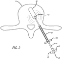
FIG. 2 is a partially cross-sectional plan view of the microwave antenna of the system shown inFIG. 1 for use in tumor ablation and vertebral compression fracture repair showing the balloon partially inflated inside the fractured vertebral body; -
FIG. 3A is a cross-sectional view of the distal end of the microwave antenna for use in tumor ablation and vertebral compression fracture repair showing saline inflating the balloon; -
FIG. 3B is an enlarged cross-sectional view of the antenna show inFIG. 3A . -
FIG. 3C is a cross-sectional view of an alternative embodiment of the antenna show inFIGS. 3A and 3B . - Other embodiments of the invention will be apparent to those skilled in the art from consideration of the specification and practice of the invention disclosed herein. It is intended that the embodiments described below be considered as exemplary only, with a true scope of the invention being indicated by the appended claims.
- The detailed description of the invention below is described for, and shown in the figures for, use in a fractured vertebral body V. However, it should be understood that the invention could be used for tumor ablation as well as reduction in any bone.
- As shown in
FIGS. 1-3A , asystem 10 for use in tumor ablation includes amicrowave antenna 20 and aballoon 50 configured to be attached to the distal end ofantenna 20.Balloon 50 and the majority of the length ofmicrowave antenna 20 is sized and configured to be inserted through acannula 60 into an opening prepared in fractured vertebral body V. - As shown in
FIGS. 3A and 3B ,antenna 20 includes aninner conductor 21 which extends along a length ofantenna 20.Inner conductor 21 may be constructed of copper or any other conductive material suitable for transmission of microwave energy.Antenna 20 further includes adielectric layer 22 surroundinginner conductor 21.Dielectric layer 22 may be constructed of Teflon™ (polytetrafluoroethene, PTFE) or any other material suitable for use as a dielectric.Dielectric layer 22 is surrounded by anouter conductor 24 constructed of copper or any other suitable conductive material.Outer conductor 24 is surrounded by ashield 25 to electrically and thermally insulateouter conductor 24.Outer conductor 24,inner conductor 21, and dielectric 22 form a coaxial structure.Antenna 20 may further include a handle 26 (FIGS. 1 and2 ) at the proximal end thereof to control the movement ofantenna 20. - As shown in
FIG. 3A ,inner conductor 21 extends beyond the distal ends ofdielectric layer 22,outer conductor 24, andshield 25, such thatinner conductor 21 extends intoballoon 50 whenballoon 50 is attached to the distal end ofantenna 20.Balloon 50 may include aflexible member 52 attached to the distal end ofballoon 50. Alternatively, the distal end offlexible member 52 may be free floating. A further alternative may includeinner conductor 21 attached to the distal end ofballoon 50. Proximal end offlexible member 52 is configured to attach to distal end ofinner conductor 21 through a banding process. - As shown in
FIGS. 1 and2 ,antenna 20 includes afluid port 30 proximate the proximal end ofantenna 20.Fluid port 30 facilitates attachment of ahigh pressure syringe 34 viatubing 32.High pressure syringe 34 includes abarrel 35 and aplunger 36.Fluid port 30 is in communication with a channel 23 (FIGS. 3A and 3B ), or alternatively, multiple channels 23 (FIG. C).Channel 23 runs the length ofantenna 20 throughdielectric layer 22 and communicates with the interior ofballoon 50. As such, pressingplunger 36forces saline 38 and contrast material out ofbarrel 35 throughtubing 32,fluid port 30, andchannel 23, and intoballoon 50. The increase of volume ofsaline 38 and contrast material inballoon 50 causesballoon 50 to inflate. The inflation ofballoon 50 causesballoon 50 to apply pressure to the tumor, ensuring a good contact betweenballoon 50 and vertebral body V. Continued inflation ofballoon 50 causes the cancellous bone to be pressed outward toward the cortical layer of fractured vertebralbody V. Balloon 50 is inflated until fractured vertebral body V achieves the desired corrected height. - As shown in
FIGS. 1 and2 ,antenna 20 includes anenergy port 40 proximate the proximal end ofantenna 20.Energy port 40 facilitates attachment of amicrowave generator 44 via acoaxial cable 42.Energy port 40 facilitates the transmission of microwave energy fromcoaxial cable 42 to inner andouter conductors antenna 20. The microwave energy exiting the distal end ofantenna 20 heats thesaline 38 withinballoon 50. Theheated saline 38 conducts heat to the tumor. The conducted heat is used to destroy the tumor. The microwave energy preferentially heats the saline and contrast mixture and therefore reduces the negative impact of microwave energy to adjacent vital structures. The direct heating effect of microwave ablation is replaced by indirect heating through conduction. As such, since most of the microwave energy is used to heat the saline and contrast mixture, the present invention will reduce harmful effects of microwave energy on the adjacent structures. In addition, performing the balloon inflation simultaneously with the ablation will reduce the duration of the procedure and may help the balloon kyphoplasty procedure as the bone softens. The temperature of theheated saline 38 may be monitored via a temperature probe (not shown) located at the distal end of the microwave antenna or at the distal end ofouter conductor 24. The temperature insideballoon 50 may be monitored with a temperature sensing element such as RTD, TC, fiber optic thermometer or radiometry. -
T system 10 can be utilized in the following manner. The preferred method includes placing the patient in the prone position and making a small incision in the skin over fractured vertebral body V. The surgeon then inserts acannula 60 through the incision into contact with fractured vertebral body V. The surgeon may manipulate the position of thecannula 60 by grasping ahandle 62 located at the proximal end ofcannula 60. When thecannula 60 is properly aligned, the surgeon introduces a drill (not shown) throughcannula 60 and creates an opening in fractured vertebral body V and into the tumor. The surgeon withdrawals the drill and insertsantenna 20 throughcannula 60 untilballoon 50 is positioned within the opening created in fractured vertebral body V. Withballoon 50 in the opening, the surgeon depressesplunger 36 onhigh pressure syringe 34, forcingsaline 38 and the contrast material intoballoon 50. Thesaline 38 inflatesballoon 50, causingballoon 50 to press against the tumor. Withballoon 50 pressing against the tumor, the surgeon turns onmicrowave generator 44. The microwave energy heatssaline 38 inballoon 50.Saline 38 conducts the heat into the tumor. After the heat destroys the tumor,microwave generator 44 is turned off. At this point, the surgeon further depressesplunger 36, causing further inflation ofballoon 50 until the correct height of fractured vertebral body V is achieved. When the correct height is achieved,balloon 50 is deflated and removed from fractured vertebral body V, leaving a larger cavity in fractured vertebral body V. The cavity in fractured vertebral body V is then filled with polymethyl methacrylate ("PMMA") bone cement. - Alternatively, the surgeon may continue reduction of fractured vertebral body V during the application of microwave energy. In addition, part or all of the procedure may be performed on both sides of fractured vertebral body V at the same time.
- There is disclosed in the above description and the drawings, tumor ablation systems, which fully and effectively accomplish the objectives of this invention. It will be apparent, however, that variations and modifications of the disclosed embodiments may be made without departing from the scope of the appended claims.
Claims (9)
- A system (10) for use in tumor ablation, the system (10) comprising:a microwave antenna (20) having a proximal end and a distal end opposite the proximal end, the microwave antenna (20) further including an inner conductor (21) and an outer conductor (24), wherein the outer conductor (24) and the inner conductor (21) form a coaxial structure;a dielectric (22) separating the inner conductor (21) and the outer conductor (24), wherein the dielectric (22) includes at least one channel (23) that extends along the length of the antenna (20) between the proximal and distal ends;an energy port (40) proximate the proximal end of the microwave antenna (20) configured to connect the antenna (20) to an energy source;a fluid port (30) proximate the proximal end of the microwave antenna (20) configured to connect the channel (23) to a fluid delivery mechanism;an inflatable balloon (50) configured to be attached to the distal end of the antenna (20), the channel (23) permitting fluid (38) access to an interior of the balloon (50) for inflation thereof and the inner conductor (21) extending beyond a distal end of the outer conductor (24) and the dielectric (22), such that the inner conductor (21) extends into the balloon (50) when the balloon (50) is attached to the distal end of the antenna (20);characterised in that a flexible member (52) connects a distal end of the inner conductor (21) to a distal end of the balloon (50).
- The system (10) of claim 1, further comprising a cannula (60) sized to allow the antenna (20) to pass therethrough.
- The system (10) of claim 1, wherein the fluid delivery mechanism includes a syringe (34) connected to the fluid port (30).
- The system (10) of claim 1, wherein the energy source includes a microwave generator (44) connected to the energy port (40).
- The system (10) ofclaim 1, further comprising a handle (26) affixed to the proximal end of the antenna (20).
- The system (10) of claim 1, wherein the balloon (50) comprises polyurethane.
- The system (10) of claim 1, further comprising a temperature probe at the proximal end of the microwave antenna (20).
- The system (10) of claim 1, wherein the inner conductor (21) of the microwave antenna (20) is copper.
- The system (10) of claim 1, wherein a dielectric (22) is positioned between the inner conductor (21) and the outer conductor (24), the dielectric (22) being made of polytetrafluoroethene.
Applications Claiming Priority (2)
| Application Number | Priority Date | Filing Date | Title |
|---|---|---|---|
| US14/593,542 US10231770B2 (en) | 2015-01-09 | 2015-01-09 | Tumor ablation system |
| PCT/US2016/012568 WO2016112240A1 (en) | 2015-01-09 | 2016-01-08 | Tumor ablation system |
Publications (3)
| Publication Number | Publication Date |
|---|---|
| EP3242620A1 EP3242620A1 (en) | 2017-11-15 |
| EP3242620A4 EP3242620A4 (en) | 2018-08-08 |
| EP3242620B1 true EP3242620B1 (en) | 2020-02-26 |
Family
ID=56356444
Family Applications (1)
| Application Number | Title | Priority Date | Filing Date |
|---|---|---|---|
| EP16735443.0A Active EP3242620B1 (en) | 2015-01-09 | 2016-01-08 | Tumor ablation system |
Country Status (5)
| Country | Link |
|---|---|
| US (2) | US10231770B2 (en) |
| EP (1) | EP3242620B1 (en) |
| CN (1) | CN107106235A (en) |
| AU (1) | AU2016205167B2 (en) |
| WO (1) | WO2016112240A1 (en) |
Families Citing this family (20)
| Publication number | Priority date | Publication date | Assignee | Title |
|---|---|---|---|---|
| US8361067B2 (en) | 2002-09-30 | 2013-01-29 | Relievant Medsystems, Inc. | Methods of therapeutically heating a vertebral body to treat back pain |
| CA2737374C (en) | 2008-09-26 | 2017-03-28 | Relievant Medsystems, Inc. | Systems and methods for navigating an instrument through bone |
| US10028753B2 (en) | 2008-09-26 | 2018-07-24 | Relievant Medsystems, Inc. | Spine treatment kits |
| US10390877B2 (en) | 2011-12-30 | 2019-08-27 | Relievant Medsystems, Inc. | Systems and methods for treating back pain |
| US10588691B2 (en) | 2012-09-12 | 2020-03-17 | Relievant Medsystems, Inc. | Radiofrequency ablation of tissue within a vertebral body |
| IL238516B (en) | 2012-11-05 | 2022-08-01 | Relievant Medsystems Inc | System and methods for creating curved paths through bone and modulating nerves within the bone |
| US9724151B2 (en) | 2013-08-08 | 2017-08-08 | Relievant Medsystems, Inc. | Modulating nerves within bone using bone fasteners |
| CN109464186B (en) | 2017-09-08 | 2023-12-22 | 泽丹医疗股份有限公司 | Devices and methods for treating lung tumors |
| US20200305974A1 (en) * | 2019-03-25 | 2020-10-01 | Covidien Lp | Pulmonary denervation with bronchial-centered dielectric heating element |
| KR102186994B1 (en) * | 2019-04-18 | 2020-12-04 | 가톨릭대학교 산학협력단 | Bone tumor surgery device |
| US10820933B1 (en) | 2019-07-15 | 2020-11-03 | Osteon Medical LLC | Kyphoplasty system and method |
| AU2020346827B2 (en) | 2019-09-12 | 2026-03-12 | Relievant Medsystems, Inc. | Systems and methods for tissue modulation |
| AU2021306313B2 (en) | 2020-07-10 | 2026-07-09 | Relievant Medsystems, Inc. | Vertebral denervation in conjunction with vertebral fusion |
| JP7840333B2 (en) | 2020-08-28 | 2026-04-03 | ジダン メディカル インコーポレイテッド | Systems and devices for treating lung tumors |
| US12082876B1 (en) | 2020-09-28 | 2024-09-10 | Relievant Medsystems, Inc. | Introducer drill |
| AU2021409967A1 (en) | 2020-12-22 | 2023-08-03 | Relievant Medsystems, Inc. | Prediction of candidates for spinal neuromodulation |
| US11103290B1 (en) | 2021-01-25 | 2021-08-31 | Osteon Medical LLC | Kyphoplasty system and method |
| US12433668B1 (en) | 2021-11-08 | 2025-10-07 | Relievant Medsystems, Inc. | Impedance stoppage mitigation during radiofrequency tissue ablation procedures |
| EP4694809A1 (en) * | 2023-04-13 | 2026-02-18 | Medtronic Europe Sàrl | Systems for injecting reinforcement material into an anatomical element |
| US11903628B1 (en) | 2023-04-20 | 2024-02-20 | Osteon Medical LLC | Kyphoplasty system and method |
Family Cites Families (80)
| Publication number | Priority date | Publication date | Assignee | Title |
|---|---|---|---|---|
| US3211150A (en) | 1963-08-15 | 1965-10-12 | Foderick John Walter | Balloon catheter with integral valves controlling inflation |
| US4921483A (en) | 1985-12-19 | 1990-05-01 | Leocor, Inc. | Angioplasty catheter |
| US4773393A (en) | 1986-07-03 | 1988-09-27 | C. R. Bard, Inc. | Hypodermically implantable genitourinary prosthesis |
| EP0415997A4 (en) | 1988-05-18 | 1992-04-08 | Kasevich Associates, Inc. | Microwave balloon angioplasty |
| WO1994007446A1 (en) | 1992-10-05 | 1994-04-14 | Boston Scientific Corporation | Device and method for heating tissue |
| US6716216B1 (en) | 1998-08-14 | 2004-04-06 | Kyphon Inc. | Systems and methods for treating vertebral bodies |
| US20030032963A1 (en) | 2001-10-24 | 2003-02-13 | Kyphon Inc. | Devices and methods using an expandable body with internal restraint for compressing cancellous bone |
| US5843116A (en) | 1996-05-02 | 1998-12-01 | Cardiovascular Dynamics, Inc. | Focalized intraluminal balloons |
| CA2184056C (en) | 1994-03-01 | 2007-09-11 | Bruce S. Hamilton | Asymmetric dilatation balloon |
| US5749851A (en) | 1995-03-02 | 1998-05-12 | Scimed Life Systems, Inc. | Stent installation method using balloon catheter having stepped compliance curve |
| WO2006053312A1 (en) | 1995-06-07 | 2006-05-18 | Kyphon Inc. | System and method for delivering a therapeutic agent for bone disease |
| US6458096B1 (en) | 1996-04-01 | 2002-10-01 | Medtronic, Inc. | Catheter with autoinflating, autoregulating balloon |
| US6241727B1 (en) * | 1998-05-27 | 2001-06-05 | Irvine Biomedical, Inc. | Ablation catheter system having circular lesion capabilities |
| US6427089B1 (en) * | 1999-02-19 | 2002-07-30 | Edward W. Knowlton | Stomach treatment apparatus and method |
| US6364900B1 (en) | 1999-07-14 | 2002-04-02 | Richard R. Heuser | Embolism prevention device |
| JP2003507096A (en) | 1999-08-12 | 2003-02-25 | ウイルソンークック メディカル インク. | Dilatation balloon with multiple meridians |
| US6230060B1 (en) | 1999-10-22 | 2001-05-08 | Daniel D. Mawhinney | Single integrated structural unit for catheter incorporating a microwave antenna |
| US7670327B2 (en) | 2000-01-20 | 2010-03-02 | Regents Of The University Of Minnesota | Catheter systems for delivery of agents and related method thereof |
| DE10010467C2 (en) | 2000-03-03 | 2002-10-31 | Gip Medizintechnik Gmbh | Balloon catheter for performing cutting processes in the tissue of individuals, in particular in the cardio and / or gastro area |
| US6416457B1 (en) | 2000-03-09 | 2002-07-09 | Scimed Life Systems, Inc. | System and method for intravascular ionizing tandem radiation therapy |
| US6544224B1 (en) | 2000-05-05 | 2003-04-08 | Advanced Cardiovascular Systems, Inc. | Lobed balloon catheter and method of use |
| US6595950B1 (en) | 2000-05-11 | 2003-07-22 | Zevex, Inc. | Apparatus and method for preventing free flow in an infusion line |
| CN1192750C (en) | 2000-08-28 | 2005-03-16 | 迪斯科动力学公司 | Prosthesis of vertebral disc |
| US6951569B2 (en) | 2000-12-27 | 2005-10-04 | Ethicon, Inc. | Surgical balloon having varying wall thickness |
| US6527739B1 (en) | 2000-12-29 | 2003-03-04 | Advanced Cardiovascular Systems, Inc. | Spiraled balloon arrangement for treatment of a tortuous vessel |
| US6911038B2 (en) | 2001-05-08 | 2005-06-28 | Scimed Life Systems, Inc. | Matched balloon to stent shortening |
| US20030028251A1 (en) | 2001-07-30 | 2003-02-06 | Mathews Hallett H. | Methods and devices for interbody spinal stabilization |
| WO2003059437A2 (en) * | 2002-01-15 | 2003-07-24 | The Regents Of The University Of California | System and method providing directional ultrasound therapy to skeletal joints |
| US7197363B2 (en) | 2002-04-16 | 2007-03-27 | Vivant Medical, Inc. | Microwave antenna having a curved configuration |
| GB2390545B (en) * | 2002-07-09 | 2005-04-20 | Barts & London Nhs Trust | Hollow organ probe |
| US20040186471A1 (en) | 2002-12-07 | 2004-09-23 | Sdgi Holdings, Inc. | Method and apparatus for intervertebral disc expansion |
| US6847848B2 (en) * | 2003-01-07 | 2005-01-25 | Mmtc, Inc | Inflatable balloon catheter structural designs and methods for treating diseased tissue of a patient |
| KR20060115900A (en) | 2004-01-06 | 2006-11-10 | 도레이 가부시끼가이샤 | Balun catheter |
| US7537580B2 (en) | 2004-06-23 | 2009-05-26 | Boston Scientific Scimed, Inc. | Intravascular dilatation infusion catheter |
| US20060034886A1 (en) | 2004-07-23 | 2006-02-16 | Ward Bennett C | Bonded fiber structures for use in controlling fluid flow |
| US7682378B2 (en) | 2004-11-10 | 2010-03-23 | Dfine, Inc. | Bone treatment systems and methods for introducing an abrading structure to abrade bone |
| US9713698B2 (en) | 2006-01-25 | 2017-07-25 | Mayser, Llc | Stretch valve balloon catheter and methods for producing and using same |
| US7826904B2 (en) | 2006-02-07 | 2010-11-02 | Angiodynamics, Inc. | Interstitial microwave system and method for thermal treatment of diseases |
| KR100787391B1 (en) | 2006-09-01 | 2007-12-21 | 안용철 | Balloon Catheter for Spinal Therapy |
| US20080249604A1 (en) | 2007-03-30 | 2008-10-09 | Brian Donovan | Apparatus and method for medical procedures within a spine |
| US20090088788A1 (en) | 2007-09-28 | 2009-04-02 | Steven Mouw | Methods and apparatus having multiple separately actuatable expandable members |
| US8403885B2 (en) | 2007-12-17 | 2013-03-26 | Abbott Cardiovascular Systems Inc. | Catheter having transitioning shaft segments |
| US8034022B2 (en) | 2008-04-08 | 2011-10-11 | Cook Medical Technologies Llc | Weeping balloon catheter |
| US20090299373A1 (en) * | 2008-05-30 | 2009-12-03 | Cook Incorporated | Kyphoplasty banded balloon catheter |
| US20090299401A1 (en) | 2008-06-02 | 2009-12-03 | Loma Vista Medical, Inc. | Inflatable medical devices |
| US8679106B2 (en) * | 2008-07-01 | 2014-03-25 | Medwaves, Inc. | Angioplasty and tissue ablation apparatus and method |
| US8382746B2 (en) | 2008-11-21 | 2013-02-26 | C2 Therapeutics, Inc. | Cryogenic ablation system and method |
| US8552915B2 (en) * | 2009-06-19 | 2013-10-08 | Covidien Lp | Microwave ablation antenna radiation detector |
| US20110028981A1 (en) | 2009-07-29 | 2011-02-03 | Warsaw Orthopedic, Inc. | Bone graft measuring apparatus and method of use |
| US8262609B2 (en) | 2009-10-29 | 2012-09-11 | Kyphon Sarl | Anterior inflation balloon |
| US8221349B2 (en) | 2009-10-29 | 2012-07-17 | Kyphon Sarl | Anterior inflation balloon |
| US20110125148A1 (en) * | 2009-11-17 | 2011-05-26 | Turner Paul F | Multiple Frequency Energy Supply and Coagulation System |
| US9358058B2 (en) | 2012-11-05 | 2016-06-07 | Globus Medical, Inc. | Methods and apparatus for treating vertebral fractures |
| US8734458B2 (en) | 2009-12-07 | 2014-05-27 | Globus Medical, Inc. | Methods and apparatus for treating vertebral fractures |
| US9220554B2 (en) | 2010-02-18 | 2015-12-29 | Globus Medical, Inc. | Methods and apparatus for treating vertebral fractures |
| US9681973B2 (en) | 2010-02-25 | 2017-06-20 | Reshape Medical, Inc. | Enhanced explant processes and mechanisms for intragastric devices |
| US20110319880A1 (en) * | 2010-06-25 | 2011-12-29 | Vivant Medical, Inc | Microwave Ground Plane Antenna Probe |
| US9327101B2 (en) | 2010-09-17 | 2016-05-03 | Abbott Cardiovascular Systems Inc. | Length and diameter adjustable balloon catheter |
| US9060755B2 (en) | 2010-10-26 | 2015-06-23 | Medtronic Ardian Luxembourg S.A.R.L. | Neuromodulation cryotherapeutic devices and associated systems and methods |
| EP2654584A1 (en) | 2010-12-22 | 2013-10-30 | Illuminoss Medical, Inc. | Systems and methods for treating conditions and diseases of the spine |
| US20120197319A1 (en) | 2011-01-27 | 2012-08-02 | Kyphon Sarl | Inflatable bone tamp with adjustable working length |
| US8961525B2 (en) | 2011-01-28 | 2015-02-24 | Kyphon Sarl | Inflatable bone tamp with predetermined extensibility |
| US9492190B2 (en) | 2011-02-09 | 2016-11-15 | Covidien Lp | Tissue dissectors |
| EP2693971B1 (en) * | 2011-04-08 | 2016-07-13 | Covidien LP | Flexible microwave catheters for natural or artificial lumens |
| WO2013074933A1 (en) | 2011-11-17 | 2013-05-23 | Beth Israel Deaconess Medical Center | Systems and methods for minimally invasive fracture reduction and fixation |
| US20140303730A1 (en) | 2011-11-30 | 2014-10-09 | Beth Israel Deaconess Medical Center | Systems and methods for endoscopic vertebral fusion |
| KR101164852B1 (en) | 2011-12-05 | 2012-07-11 | 최길운 | Balloon catheter |
| WO2013129087A1 (en) | 2012-03-01 | 2013-09-06 | テルモ株式会社 | Device for gastrointestinal tract |
| US20130238038A1 (en) | 2012-03-07 | 2013-09-12 | Kyphon Sarl | Angled inflatable composite balloon and method |
| US9517151B2 (en) | 2012-03-30 | 2016-12-13 | Abbott Cardiovascular Systems Inc. | Control of balloon inflation rate during deployment of scaffold |
| CN104487854B (en) * | 2012-03-31 | 2018-05-04 | 微立方有限责任公司 | Return power for microwave applications |
| US9289319B2 (en) | 2012-05-14 | 2016-03-22 | Abbott Cardiovascular Systems Inc. | Flow regulation valve for controlling inflation rate of a balloon deploying a scaffold |
| US9572676B2 (en) | 2013-03-14 | 2017-02-21 | DePuy Synthes Products, Inc. | Adjustable multi-volume balloon for spinal interventions |
| US9730746B2 (en) | 2013-03-15 | 2017-08-15 | Kyphon SÀRL | Device for performing a surgical procedure and method |
| JP6152029B2 (en) | 2013-09-27 | 2017-06-21 | テルモ株式会社 | Bone treatment system |
| US9936997B2 (en) | 2014-05-28 | 2018-04-10 | Kyphon SÀRL | Cryogenic kyphoplasty instrument and methods of use |
| US20150359432A1 (en) * | 2014-06-11 | 2015-12-17 | Sympara Medical, Inc. | Methods and devices for detecting nerve activity |
| US10398484B2 (en) | 2016-06-22 | 2019-09-03 | Medtronic Holding Company Sárl | Inflatable bone tamp with flow control and methods of use |
| US10779870B2 (en) | 2017-10-16 | 2020-09-22 | Medtronic Holding Company Sarl | Curved inflatable bone tamp with variable wall thickness |
| CN110378799B (en) | 2019-07-16 | 2022-07-12 | 东北大学 | Alumina comprehensive production index decision method based on multi-scale deep convolution network |
-
2015
- 2015-01-09 US US14/593,542 patent/US10231770B2/en active Active
-
2016
- 2016-01-08 EP EP16735443.0A patent/EP3242620B1/en active Active
- 2016-01-08 CN CN201680005267.7A patent/CN107106235A/en active Pending
- 2016-01-08 WO PCT/US2016/012568 patent/WO2016112240A1/en not_active Ceased
- 2016-01-08 AU AU2016205167A patent/AU2016205167B2/en active Active
-
2019
- 2019-02-07 US US16/269,997 patent/US11744630B2/en active Active
Non-Patent Citations (1)
| Title |
|---|
| None * |
Also Published As
| Publication number | Publication date |
|---|---|
| US20190167333A1 (en) | 2019-06-06 |
| CN107106235A (en) | 2017-08-29 |
| US11744630B2 (en) | 2023-09-05 |
| US20160199117A1 (en) | 2016-07-14 |
| EP3242620A4 (en) | 2018-08-08 |
| AU2016205167B2 (en) | 2019-09-19 |
| EP3242620A1 (en) | 2017-11-15 |
| WO2016112240A1 (en) | 2016-07-14 |
| US10231770B2 (en) | 2019-03-19 |
| AU2016205167A1 (en) | 2017-07-13 |
Similar Documents
| Publication | Publication Date | Title |
|---|---|---|
| US11744630B2 (en) | Tumor ablation system | |
| EP3569177B1 (en) | Electrosurgical device | |
| CN105025832B (en) | Vertebra inner tissue ablating device and method | |
| US9907595B2 (en) | Systems and methods for vertebral or other bone structure height restoration and stabilization | |
| KR101179856B1 (en) | Insertion devices and method of use | |
| CN107106200B (en) | System and method for percutaneous segmentation of fibrous structures | |
| US6245067B1 (en) | Ablation device and methods having perpendicular electrodes | |
| US20130085493A1 (en) | Electrosurgical Balloons | |
| US20110251525A1 (en) | Systems and methods for treating lung tissue | |
| US20120265186A1 (en) | Steerable curvable ablation catheter for vertebroplasty | |
| KR20110063551A (en) | Pressurization of the catheter balloon | |
| US11033313B2 (en) | Adjustable balloon including bone access tip | |
| KR101954705B1 (en) | High-frequency treatment device for endoscopic spinal surgery | |
| CN102784434A (en) | Bone filler conveying sleeve | |
| US20140316411A1 (en) | Systems and methods for minimally invasive fracture reduction and fixation | |
| EP2853211B1 (en) | Bone treatment system | |
| US20190307499A1 (en) | Ablation device having a sheath with a dilatable member for fixation and/or support of an ablation applicator, and method of operating an ablation device | |
| CN105792765A (en) | Apparatus for creating linear lesions in body tissue within a body vessel | |
| KR20180052450A (en) | Apparatus drug mixed steam for adjuvant therapy of metastatic bone tumor |
Legal Events
| Date | Code | Title | Description |
|---|---|---|---|
| STAA | Information on the status of an ep patent application or granted ep patent |
Free format text: STATUS: THE INTERNATIONAL PUBLICATION HAS BEEN MADE |
|
| PUAI | Public reference made under article 153(3) epc to a published international application that has entered the european phase |
Free format text: ORIGINAL CODE: 0009012 |
|
| STAA | Information on the status of an ep patent application or granted ep patent |
Free format text: STATUS: REQUEST FOR EXAMINATION WAS MADE |
|
| 17P | Request for examination filed |
Effective date: 20170703 |
|
| AK | Designated contracting states |
Kind code of ref document: A1 Designated state(s): AL AT BE BG CH CY CZ DE DK EE ES FI FR GB GR HR HU IE IS IT LI LT LU LV MC MK MT NL NO PL PT RO RS SE SI SK SM TR |
|
| AX | Request for extension of the european patent |
Extension state: BA ME |
|
| DAV | Request for validation of the european patent (deleted) | ||
| DAX | Request for extension of the european patent (deleted) | ||
| A4 | Supplementary search report drawn up and despatched |
Effective date: 20180711 |
|
| RIC1 | Information provided on ipc code assigned before grant |
Ipc: A61B 18/18 20060101AFI20180705BHEP Ipc: A61M 25/10 20130101ALI20180705BHEP |
|
| STAA | Information on the status of an ep patent application or granted ep patent |
Free format text: STATUS: EXAMINATION IS IN PROGRESS |
|
| RAP1 | Party data changed (applicant data changed or rights of an application transferred) |
Owner name: MEDTRONIC HOLDING COMPANY SARL |
|
| 17Q | First examination report despatched |
Effective date: 20190327 |
|
| GRAP | Despatch of communication of intention to grant a patent |
Free format text: ORIGINAL CODE: EPIDOSNIGR1 |
|
| STAA | Information on the status of an ep patent application or granted ep patent |
Free format text: STATUS: GRANT OF PATENT IS INTENDED |
|
| INTG | Intention to grant announced |
Effective date: 20190925 |
|
| GRAS | Grant fee paid |
Free format text: ORIGINAL CODE: EPIDOSNIGR3 |
|
| GRAA | (expected) grant |
Free format text: ORIGINAL CODE: 0009210 |
|
| STAA | Information on the status of an ep patent application or granted ep patent |
Free format text: STATUS: THE PATENT HAS BEEN GRANTED |
|
| AK | Designated contracting states |
Kind code of ref document: B1 Designated state(s): AL AT BE BG CH CY CZ DE DK EE ES FI FR GB GR HR HU IE IS IT LI LT LU LV MC MK MT NL NO PL PT RO RS SE SI SK SM TR |
|
| REG | Reference to a national code |
Ref country code: GB Ref legal event code: FG4D |
|
| REG | Reference to a national code |
Ref country code: CH Ref legal event code: EP |
|
| REG | Reference to a national code |
Ref country code: DE Ref legal event code: R096 Ref document number: 602016030575 Country of ref document: DE |
|
| REG | Reference to a national code |
Ref country code: AT Ref legal event code: REF Ref document number: 1236713 Country of ref document: AT Kind code of ref document: T Effective date: 20200315 |
|
| REG | Reference to a national code |
Ref country code: IE Ref legal event code: FG4D |
|
| PG25 | Lapsed in a contracting state [announced via postgrant information from national office to epo] |
Ref country code: FI Free format text: LAPSE BECAUSE OF FAILURE TO SUBMIT A TRANSLATION OF THE DESCRIPTION OR TO PAY THE FEE WITHIN THE PRESCRIBED TIME-LIMIT Effective date: 20200226 Ref country code: RS Free format text: LAPSE BECAUSE OF FAILURE TO SUBMIT A TRANSLATION OF THE DESCRIPTION OR TO PAY THE FEE WITHIN THE PRESCRIBED TIME-LIMIT Effective date: 20200226 Ref country code: NO Free format text: LAPSE BECAUSE OF FAILURE TO SUBMIT A TRANSLATION OF THE DESCRIPTION OR TO PAY THE FEE WITHIN THE PRESCRIBED TIME-LIMIT Effective date: 20200526 |
|
| REG | Reference to a national code |
Ref country code: NL Ref legal event code: MP Effective date: 20200226 |
|
| REG | Reference to a national code |
Ref country code: LT Ref legal event code: MG4D |
|
| PG25 | Lapsed in a contracting state [announced via postgrant information from national office to epo] |
Ref country code: BG Free format text: LAPSE BECAUSE OF FAILURE TO SUBMIT A TRANSLATION OF THE DESCRIPTION OR TO PAY THE FEE WITHIN THE PRESCRIBED TIME-LIMIT Effective date: 20200526 Ref country code: HR Free format text: LAPSE BECAUSE OF FAILURE TO SUBMIT A TRANSLATION OF THE DESCRIPTION OR TO PAY THE FEE WITHIN THE PRESCRIBED TIME-LIMIT Effective date: 20200226 Ref country code: GR Free format text: LAPSE BECAUSE OF FAILURE TO SUBMIT A TRANSLATION OF THE DESCRIPTION OR TO PAY THE FEE WITHIN THE PRESCRIBED TIME-LIMIT Effective date: 20200527 Ref country code: LV Free format text: LAPSE BECAUSE OF FAILURE TO SUBMIT A TRANSLATION OF THE DESCRIPTION OR TO PAY THE FEE WITHIN THE PRESCRIBED TIME-LIMIT Effective date: 20200226 Ref country code: SE Free format text: LAPSE BECAUSE OF FAILURE TO SUBMIT A TRANSLATION OF THE DESCRIPTION OR TO PAY THE FEE WITHIN THE PRESCRIBED TIME-LIMIT Effective date: 20200226 Ref country code: IS Free format text: LAPSE BECAUSE OF FAILURE TO SUBMIT A TRANSLATION OF THE DESCRIPTION OR TO PAY THE FEE WITHIN THE PRESCRIBED TIME-LIMIT Effective date: 20200626 |
|
| PG25 | Lapsed in a contracting state [announced via postgrant information from national office to epo] |
Ref country code: NL Free format text: LAPSE BECAUSE OF FAILURE TO SUBMIT A TRANSLATION OF THE DESCRIPTION OR TO PAY THE FEE WITHIN THE PRESCRIBED TIME-LIMIT Effective date: 20200226 |
|
| PG25 | Lapsed in a contracting state [announced via postgrant information from national office to epo] |
Ref country code: SM Free format text: LAPSE BECAUSE OF FAILURE TO SUBMIT A TRANSLATION OF THE DESCRIPTION OR TO PAY THE FEE WITHIN THE PRESCRIBED TIME-LIMIT Effective date: 20200226 Ref country code: SK Free format text: LAPSE BECAUSE OF FAILURE TO SUBMIT A TRANSLATION OF THE DESCRIPTION OR TO PAY THE FEE WITHIN THE PRESCRIBED TIME-LIMIT Effective date: 20200226 Ref country code: RO Free format text: LAPSE BECAUSE OF FAILURE TO SUBMIT A TRANSLATION OF THE DESCRIPTION OR TO PAY THE FEE WITHIN THE PRESCRIBED TIME-LIMIT Effective date: 20200226 Ref country code: CZ Free format text: LAPSE BECAUSE OF FAILURE TO SUBMIT A TRANSLATION OF THE DESCRIPTION OR TO PAY THE FEE WITHIN THE PRESCRIBED TIME-LIMIT Effective date: 20200226 Ref country code: PT Free format text: LAPSE BECAUSE OF FAILURE TO SUBMIT A TRANSLATION OF THE DESCRIPTION OR TO PAY THE FEE WITHIN THE PRESCRIBED TIME-LIMIT Effective date: 20200719 Ref country code: LT Free format text: LAPSE BECAUSE OF FAILURE TO SUBMIT A TRANSLATION OF THE DESCRIPTION OR TO PAY THE FEE WITHIN THE PRESCRIBED TIME-LIMIT Effective date: 20200226 Ref country code: ES Free format text: LAPSE BECAUSE OF FAILURE TO SUBMIT A TRANSLATION OF THE DESCRIPTION OR TO PAY THE FEE WITHIN THE PRESCRIBED TIME-LIMIT Effective date: 20200226 Ref country code: EE Free format text: LAPSE BECAUSE OF FAILURE TO SUBMIT A TRANSLATION OF THE DESCRIPTION OR TO PAY THE FEE WITHIN THE PRESCRIBED TIME-LIMIT Effective date: 20200226 Ref country code: DK Free format text: LAPSE BECAUSE OF FAILURE TO SUBMIT A TRANSLATION OF THE DESCRIPTION OR TO PAY THE FEE WITHIN THE PRESCRIBED TIME-LIMIT Effective date: 20200226 |
|
| REG | Reference to a national code |
Ref country code: AT Ref legal event code: MK05 Ref document number: 1236713 Country of ref document: AT Kind code of ref document: T Effective date: 20200226 |
|
| REG | Reference to a national code |
Ref country code: DE Ref legal event code: R097 Ref document number: 602016030575 Country of ref document: DE |
|
| PLBE | No opposition filed within time limit |
Free format text: ORIGINAL CODE: 0009261 |
|
| STAA | Information on the status of an ep patent application or granted ep patent |
Free format text: STATUS: NO OPPOSITION FILED WITHIN TIME LIMIT |
|
| PG25 | Lapsed in a contracting state [announced via postgrant information from national office to epo] |
Ref country code: IT Free format text: LAPSE BECAUSE OF FAILURE TO SUBMIT A TRANSLATION OF THE DESCRIPTION OR TO PAY THE FEE WITHIN THE PRESCRIBED TIME-LIMIT Effective date: 20200226 Ref country code: AT Free format text: LAPSE BECAUSE OF FAILURE TO SUBMIT A TRANSLATION OF THE DESCRIPTION OR TO PAY THE FEE WITHIN THE PRESCRIBED TIME-LIMIT Effective date: 20200226 |
|
| 26N | No opposition filed |
Effective date: 20201127 |
|
| PG25 | Lapsed in a contracting state [announced via postgrant information from national office to epo] |
Ref country code: PL Free format text: LAPSE BECAUSE OF FAILURE TO SUBMIT A TRANSLATION OF THE DESCRIPTION OR TO PAY THE FEE WITHIN THE PRESCRIBED TIME-LIMIT Effective date: 20200226 Ref country code: SI Free format text: LAPSE BECAUSE OF FAILURE TO SUBMIT A TRANSLATION OF THE DESCRIPTION OR TO PAY THE FEE WITHIN THE PRESCRIBED TIME-LIMIT Effective date: 20200226 |
|
| PG25 | Lapsed in a contracting state [announced via postgrant information from national office to epo] |
Ref country code: MC Free format text: LAPSE BECAUSE OF FAILURE TO SUBMIT A TRANSLATION OF THE DESCRIPTION OR TO PAY THE FEE WITHIN THE PRESCRIBED TIME-LIMIT Effective date: 20200226 |
|
| REG | Reference to a national code |
Ref country code: CH Ref legal event code: PL |
|
| GBPC | Gb: european patent ceased through non-payment of renewal fee |
Effective date: 20210108 |
|
| PG25 | Lapsed in a contracting state [announced via postgrant information from national office to epo] |
Ref country code: LU Free format text: LAPSE BECAUSE OF NON-PAYMENT OF DUE FEES Effective date: 20210108 |
|
| REG | Reference to a national code |
Ref country code: BE Ref legal event code: MM Effective date: 20210131 |
|
| PG25 | Lapsed in a contracting state [announced via postgrant information from national office to epo] |
Ref country code: GB Free format text: LAPSE BECAUSE OF NON-PAYMENT OF DUE FEES Effective date: 20210108 Ref country code: LI Free format text: LAPSE BECAUSE OF NON-PAYMENT OF DUE FEES Effective date: 20210131 Ref country code: CH Free format text: LAPSE BECAUSE OF NON-PAYMENT OF DUE FEES Effective date: 20210131 |
|
| PG25 | Lapsed in a contracting state [announced via postgrant information from national office to epo] |
Ref country code: IE Free format text: LAPSE BECAUSE OF NON-PAYMENT OF DUE FEES Effective date: 20210108 |
|
| PG25 | Lapsed in a contracting state [announced via postgrant information from national office to epo] |
Ref country code: BE Free format text: LAPSE BECAUSE OF NON-PAYMENT OF DUE FEES Effective date: 20210131 |
|
| PG25 | Lapsed in a contracting state [announced via postgrant information from national office to epo] |
Ref country code: HU Free format text: LAPSE BECAUSE OF FAILURE TO SUBMIT A TRANSLATION OF THE DESCRIPTION OR TO PAY THE FEE WITHIN THE PRESCRIBED TIME-LIMIT; INVALID AB INITIO Effective date: 20160108 |
|
| PG25 | Lapsed in a contracting state [announced via postgrant information from national office to epo] |
Ref country code: CY Free format text: LAPSE BECAUSE OF FAILURE TO SUBMIT A TRANSLATION OF THE DESCRIPTION OR TO PAY THE FEE WITHIN THE PRESCRIBED TIME-LIMIT Effective date: 20200226 |
|
| PG25 | Lapsed in a contracting state [announced via postgrant information from national office to epo] |
Ref country code: MK Free format text: LAPSE BECAUSE OF FAILURE TO SUBMIT A TRANSLATION OF THE DESCRIPTION OR TO PAY THE FEE WITHIN THE PRESCRIBED TIME-LIMIT Effective date: 20200226 |
|
| PG25 | Lapsed in a contracting state [announced via postgrant information from national office to epo] |
Ref country code: TR Free format text: LAPSE BECAUSE OF FAILURE TO SUBMIT A TRANSLATION OF THE DESCRIPTION OR TO PAY THE FEE WITHIN THE PRESCRIBED TIME-LIMIT Effective date: 20200226 |
|
| PG25 | Lapsed in a contracting state [announced via postgrant information from national office to epo] |
Ref country code: MT Free format text: LAPSE BECAUSE OF FAILURE TO SUBMIT A TRANSLATION OF THE DESCRIPTION OR TO PAY THE FEE WITHIN THE PRESCRIBED TIME-LIMIT Effective date: 20200226 |
|
| PGFP | Annual fee paid to national office [announced via postgrant information from national office to epo] |
Ref country code: FR Payment date: 20241219 Year of fee payment: 10 |
|
| PGFP | Annual fee paid to national office [announced via postgrant information from national office to epo] |
Ref country code: DE Payment date: 20251217 Year of fee payment: 11 |