EP3242413A1 - Power system for a satellite - Google Patents
Power system for a satellite Download PDFInfo
- Publication number
- EP3242413A1 EP3242413A1 EP17177334.4A EP17177334A EP3242413A1 EP 3242413 A1 EP3242413 A1 EP 3242413A1 EP 17177334 A EP17177334 A EP 17177334A EP 3242413 A1 EP3242413 A1 EP 3242413A1
- Authority
- EP
- European Patent Office
- Prior art keywords
- power
- high power
- power amplifier
- amplifier
- satellite
- Prior art date
- Legal status (The legal status is an assumption and is not a legal conclusion. Google has not performed a legal analysis and makes no representation as to the accuracy of the status listed.)
- Granted
Links
Images


Classifications
-
- H—ELECTRICITY
- H04—ELECTRIC COMMUNICATION TECHNIQUE
- H04B—TRANSMISSION
- H04B7/00—Radio transmission systems, i.e. using radiation field
- H04B7/14—Relay systems
- H04B7/15—Active relay systems
- H04B7/185—Space-based or airborne stations; Stations for satellite systems
- H04B7/1851—Systems using a satellite or space-based relay
- H04B7/18515—Transmission equipment in satellites or space-based relays
-
- H—ELECTRICITY
- H03—ELECTRONIC CIRCUITRY
- H03G—CONTROL OF AMPLIFICATION
- H03G3/00—Gain control in amplifiers or frequency changers
- H03G3/20—Automatic control
- H03G3/30—Automatic control in amplifiers having semiconductor devices
- H03G3/3036—Automatic control in amplifiers having semiconductor devices in high-frequency amplifiers or in frequency-changers
- H03G3/3042—Automatic control in amplifiers having semiconductor devices in high-frequency amplifiers or in frequency-changers in modulators, frequency-changers, transmitters or power amplifiers
-
- Y—GENERAL TAGGING OF NEW TECHNOLOGICAL DEVELOPMENTS; GENERAL TAGGING OF CROSS-SECTIONAL TECHNOLOGIES SPANNING OVER SEVERAL SECTIONS OF THE IPC; TECHNICAL SUBJECTS COVERED BY FORMER USPC CROSS-REFERENCE ART COLLECTIONS [XRACs] AND DIGESTS
- Y02—TECHNOLOGIES OR APPLICATIONS FOR MITIGATION OR ADAPTATION AGAINST CLIMATE CHANGE
- Y02D—CLIMATE CHANGE MITIGATION TECHNOLOGIES IN INFORMATION AND COMMUNICATION TECHNOLOGIES [ICT], I.E. INFORMATION AND COMMUNICATION TECHNOLOGIES AIMING AT THE REDUCTION OF THEIR OWN ENERGY USE
- Y02D30/00—Reducing energy consumption in communication networks
- Y02D30/70—Reducing energy consumption in communication networks in wireless communication networks
Definitions
- the present invention relates generally to communication satellites, and more particularly, to a power control system for such satellites.
- Communication satellites use high power amplifiers that are used to increase the power of received signals.
- communication satellites typically have high power amplifiers that are grouped together in redundancy rings.
- Each high power amplifier within the ring has the same operating frequency, bandwidth, and output power.
- Boeing's commercial satellites there are forty 32 Ku-Band 120W traveling wave tube amplifiers, 24 C-Band 40W traveling wave tube amplifiers, and 38 90W Ka-Band traveling wave tube amplifiers.
- Each high power amplifier must be able to meet the effective isotropic radiated power (EIRP) requirements of the adjacent high power amplifiers within the redundancy ring. However, not all of the high power amplifiers have the identical EIRP requirements.
- EIRP effective isotropic radiated power
- the present invention reduces the amount of power consumed by the high power amplifier circuitry by controlling the saturation power of the high power amplifier.
- a power system for a satellite includes a high power amplifier that has a control input.
- the high power amplifier has a minimum effective isotropic radiated power.
- a controller is coupled to the control input. The controller generates a control signal to adjust a saturated power output of the high power amplifier to the minimum effective isotropic radiated power.
- a method for operating a satellite includes providing a plurality of high power amplifiers, each power amplifier having a minimum effective isotropic radiated power, generating a control input for a plurality of high power amplifiers, adjusting the effective saturated power output of the plurality of high power amplifiers to the minimum effective isotropic radiated power.
- One advantage of the invention is that by reducing the amount of power consumed in the high power amplifiers, the overall size of the power subsystem may be reduced or additional revenue generating transponders may be deployed on the satellite.
- Another advantage of the invention is that by reducing the saturated output power point, more DC power reduction is provided than merely backing off the drive power to the high power amplifiers.
- the present invention is applicable to various types of high power amplifiers as well as various numbers of high power amplifiers. Also, the present invention may be employed in groups or rings of high power amplifiers.
- a satellite communication system 10 is illustrated having a satellite 12 having a communication system 14 therein.
- the communication system 14 communicates with a ground station 16 on earth 18.
- a receive antenna 20 is coupled to a receiver 22.
- Receiver 22 is coupled to switches and filters 24 that process the signals in a conventional manner.
- the switches and filters divide the signals into various signal paths 26.
- Each of the signal paths has a gain control 28.
- Each gain control controls the gain in a corresponding variable power high power amplifier circuit 30.
- Each high power amplifier circuit generates a signal, each of which are coupled to switches and output multiplexer 32 which in turn is coupled to a transmit antenna 34.
- High power amplifier 30 may be one of various types of high power amplifiers including a traveling wave tube amplifier or a solid-state power amplifier.
- the communication system also has a command antenna 36.
- the command antenna receives command signals from ground station 16 shown in Figure 1 .
- Command antenna 36 is coupled to a command receiver 38, and ultimately to a spacecraft control processor or controller 40.
- Spacecraft control processor 40 may be coupled to many things, including the variable power high power amplifier circuits 30.
- High power amplifier 30 receives communication signals from receive antenna 20, receiver 22, and gain control 28.
- High power amplifier 30 also includes a power conditioner 41 and a telemetry and command interface 43 that may be part of spacecraft control processor or controller 40. Telemetry and command interface 43 may also act as a controller in and of itself.
- Power conditioner 41 includes a DC power input 42 that is used to ultimately control the saturated power of the high power amplifier.
- Telemetry and command interface 43 has a command input 44, a power level command input 46, and a telemetry output 48.
- the system works by generating a power level command from a controller to the telemetry and command interface.
- the power level command is received from the command antenna 36 that ultimately originates from the ground station 16.
- the command signal commands the power conditioner 41 to change the saturated output power point of the high power amplifier 30.
- the high power amplifier 30 may be one of several different types of amplifiers.
- the anode voltage is used by the power conditioner for power control.
- the drain voltage of a field effect transistor is used to control the saturated output power.
- Each of the high power amplifiers has a minimum isotropic radiated power.
- the minimum effective isotropic radiated power varies within the rings or groupings of the high power amplifiers. Therefore, the saturated power output of the high power amplifiers within the groups of high power amplifiers may be reduced on an individual basis to reduce the amount of power consumption for the satellite.
- FIG. 4 a comparison chart illustrating the DC input power backoff in decibels is illustrated using input power backoff versus variable power control of the present invention.
- the second, third and fourth columns illustrate two different types of traveling wave tubes and a solid-state power amplifier using traditional power backoff.
- Column 5 illustrates the power reduction using a traveling wave tube amplifier and the savings is illustrated in column 6 showing the amount of power savings using the variable power control system versus input power backoff of the prior art.
- columns 7 and 8 the solid-state power amplifier using variable power control is illustrated along with the power savings.
- a significant amount of power savings may be achieved by variable power control versus input power backoff of the prior art.
- the savings are multiplied by the number of power amplifiers employed on each satellite. The number may be significant.
Landscapes
- Engineering & Computer Science (AREA)
- Physics & Mathematics (AREA)
- Astronomy & Astrophysics (AREA)
- Aviation & Aerospace Engineering (AREA)
- General Physics & Mathematics (AREA)
- Computer Networks & Wireless Communication (AREA)
- Signal Processing (AREA)
- Amplifiers (AREA)
- Radio Relay Systems (AREA)
- Microwave Amplifiers (AREA)
Abstract
Description
- The present invention relates generally to communication satellites, and more particularly, to a power control system for such satellites.
- Communication satellites use high power amplifiers that are used to increase the power of received signals. Typically, communication satellites have high power amplifiers that are grouped together in redundancy rings. Each high power amplifier within the ring has the same operating frequency, bandwidth, and output power. For example, on one of Boeing's commercial satellites, there are forty 32 Ku-Band 120W traveling wave tube amplifiers, 24 C-Band 40W traveling wave tube amplifiers, and 38 90W Ka-Band traveling wave tube amplifiers. Each high power amplifier must be able to meet the effective isotropic radiated power (EIRP) requirements of the adjacent high power amplifiers within the redundancy ring. However, not all of the high power amplifiers have the identical EIRP requirements. Therefore, extra power is provided to high power amplifiers that have lower EIRP requirements. This is not very power efficient. Reducing the amount of power consumed by a satellite is a goal for satellite producers. Reducing the amount of power consumed by the various components allows additional transponders to be placed upon the satellite to generate additional revenue or allows the power system of the satellite to be reduced.
- It would therefore be desirable to reduce the amount of power consumed by high power amplifier circuit systems.
- The present invention reduces the amount of power consumed by the high power amplifier circuitry by controlling the saturation power of the high power amplifier.
- In one aspect of the invention, a power system for a satellite includes a high power amplifier that has a control input. The high power amplifier has a minimum effective isotropic radiated power. A controller is coupled to the control input. The controller generates a control signal to adjust a saturated power output of the high power amplifier to the minimum effective isotropic radiated power.
- In a further aspect of the invention, a method for operating a satellite includes providing a plurality of high power amplifiers, each power amplifier having a minimum effective isotropic radiated power, generating a control input for a plurality of high power amplifiers, adjusting the effective saturated power output of the plurality of high power amplifiers to the minimum effective isotropic radiated power.
- One advantage of the invention is that by reducing the amount of power consumed in the high power amplifiers, the overall size of the power subsystem may be reduced or additional revenue generating transponders may be deployed on the satellite.
- Another advantage of the invention is that by reducing the saturated output power point, more DC power reduction is provided than merely backing off the drive power to the high power amplifiers.
- Other aspects and advantages of the present invention will become apparent upon the following detailed description and appended claims, and upon reference to the accompanying drawings.
-
-
Figure 1 is an elevational view of a satellite communicating with a ground station according to the present invention. -
Figure 2 is a simplified block diagrammatic view of a satellite with a number of variable power transponders. -
Figure 3 is a detailed block diagrammatic view of a high power amplifier circuit ofFigure 2 . -
Figure 4 is a chart illustrating the amount of power savings of the present invention. -
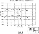
Figure 5 is a diagram illustrating the Forward Link EIRP Performance. - In the following figures the same reference numerals will be used to identify the same components.
- It should be understood that the present invention is applicable to various types of high power amplifiers as well as various numbers of high power amplifiers. Also, the present invention may be employed in groups or rings of high power amplifiers.
- Referring now to
Figure 1 , a satellite communication system 10 is illustrated having asatellite 12 having acommunication system 14 therein. Thecommunication system 14 communicates with aground station 16 onearth 18. - Referring now to
Figure 2 ,communication system 14 is illustrated in further detail. Areceive antenna 20 is coupled to areceiver 22.Receiver 22 is coupled to switches and filters 24 that process the signals in a conventional manner. The switches and filters divide the signals intovarious signal paths 26. Each of the signal paths has again control 28. Each gain control controls the gain in a corresponding variable power highpower amplifier circuit 30. Each high power amplifier circuit generates a signal, each of which are coupled to switches andoutput multiplexer 32 which in turn is coupled to atransmit antenna 34. -
High power amplifier 30 may be one of various types of high power amplifiers including a traveling wave tube amplifier or a solid-state power amplifier. - The communication system also has a
command antenna 36. The command antenna receives command signals fromground station 16 shown inFigure 1 .Command antenna 36 is coupled to acommand receiver 38, and ultimately to a spacecraft control processor orcontroller 40. Spacecraftcontrol processor 40 may be coupled to many things, including the variable power highpower amplifier circuits 30. - Referring now to
Figure 3 , a more detailed block diagrammatic view of variable highpower amplifier circuit 30 is illustrated. As in the previous figure, the high power amplifier receives communication signals from receiveantenna 20,receiver 22, andgain control 28.High power amplifier 30 also includes apower conditioner 41 and a telemetry andcommand interface 43 that may be part of spacecraft control processor orcontroller 40. Telemetry andcommand interface 43 may also act as a controller in and of itself.Power conditioner 41 includes aDC power input 42 that is used to ultimately control the saturated power of the high power amplifier. Telemetry andcommand interface 43 has acommand input 44, a powerlevel command input 46, and atelemetry output 48. - The system works by generating a power level command from a controller to the telemetry and command interface. The power level command is received from the
command antenna 36 that ultimately originates from theground station 16. The command signal commands thepower conditioner 41 to change the saturated output power point of thehigh power amplifier 30. - As mentioned above, the
high power amplifier 30 may be one of several different types of amplifiers. For a traveling wave tube amplifier, the anode voltage is used by the power conditioner for power control. For a solid-state power amplifier the drain voltage of a field effect transistor is used to control the saturated output power. - Each of the high power amplifiers has a minimum isotropic radiated power. The minimum effective isotropic radiated power varies within the rings or groupings of the high power amplifiers. Therefore, the saturated power output of the high power amplifiers within the groups of high power amplifiers may be reduced on an individual basis to reduce the amount of power consumption for the satellite.
- Referring now to
Figure 4 , a comparison chart illustrating the DC input power backoff in decibels is illustrated using input power backoff versus variable power control of the present invention. The second, third and fourth columns illustrate two different types of traveling wave tubes and a solid-state power amplifier using traditional power backoff. Column 5 illustrates the power reduction using a traveling wave tube amplifier and the savings is illustrated in column 6 showing the amount of power savings using the variable power control system versus input power backoff of the prior art. Incolumns 7 and 8, the solid-state power amplifier using variable power control is illustrated along with the power savings. As can be seen, a significant amount of power savings may be achieved by variable power control versus input power backoff of the prior art. The savings are multiplied by the number of power amplifiers employed on each satellite. The number may be significant. - Referring now to
Figure 5 , using the Boeing spacecraft described above and using the variable power control described above, the extra effective isotropic radiated power is reduced by 0.6 to 0.7dB. This corresponds to extra power saved of approximately 6%. When multiplied by the approximately 5.7kW consumed by all the Ka-Band traveling wave tube amplifiers together, a 342W savings becomes significant. InFigure 5 , the difference in the corresponding effective isotropic radiation performance is illustrated. - While the invention has been described in connection with one or more embodiments, it should be understood that the invention is not limited to those embodiments. On the contrary, the invention is intended to cover all alternatives, modifications, and equivalents, as may be included within the spirit and scope of the appended claims.
- Further, the current disclosure comprises embodiments according to the following clauses:
-
Clause 1. A power system for a satellite (12) comprising:- a high power amplifier (30) having a control input and a minimum effective isotropic radiated power; and
- a controller (40) coupled to the control input, said controller (40) generating a control signal to adjust a saturated power output of the high power amplifier (30) to the minimum effective isotropic radiated power.
-
Clause 2. The system as recited inclause 1, wherein said high power amplifier (30) comprises a traveling wave tube amplifier. -
Clause 3. The system as recited inclause 1, wherein said high power amplifier (30) comprises a solid-state power amplifier. - Clause 4. The system as recited in
clause - Clause 5. The system as recited in
clause 1, wherein said high power amplifier (30) comprises a variable power high power amplifier. - Clause 6. A satellite system comprising:
- a receiver (22) for receiving command signals;
- a power conditioner (41);
- a plurality of variable power high power amplifiers (30) coupled to the power conditioner (41);
- a controller (40) receiving command signals and generating control signals in response to the command signals; and
- said power conditioner (41) generating a control voltage in response to the control signal, said control voltage coupled to said plurality of high power amplifiers (30), said control voltage selectively reducing the saturated power of at least one of the plurality of high power amplifiers (30).
- Clause 7. The system as recited in clause 6, wherein said control voltage reduces the effective saturated power output of the plurality of high power amplifiers (30) to a minimum effective isotropic radiated power of the plurality of high power amplifiers (30).
-
Clause 8. A method for operating a satellite comprising:- providing a plurality of high power amplifiers (30) each having a minimum effective isotropic radiated power;
- generating a control input for a plurality of high power amplifiers (30); and
- adjusting the effective saturated power output of the plurality of high power amplifiers (30) to the minimum effective isotropic radiated power.
- Clause 9. The method as recited in
clause 8, wherein providing a plurality of high power amplifiers (30) comprises providing a variable power high power amplifier. - Clause 10.The method as recited in
clause 8 or 9, further comprising receiving a command signal and generating the control input as a function of the command signal (16).
Claims (5)
- A power system for a satellite (12) comprising:a high power amplifier (30) having a control input and a minimum effective isotropic radiated power; anda controller (40) coupled to the control input, said controller (40) generating a control signal to adjust a saturated power output of the high power amplifier (30) to the minimum effective isotropic radiated power.
- The system as recited in claim 1, wherein said high power amplifier (30) comprises a traveling wave tube amplifier.
- The system as recited in claim 1, wherein said high power amplifier (30) comprises a solid-state power amplifier.
- The system as recited in claim 1, 2 or 3, further comprising a power conditioner (41) coupled to the high power amplifier (30), said power conditioner (41) adjusting a control voltage for the high power amplifier (30).
- The system as recited in claim 1, wherein said high power amplifier (30) comprises a variable power high power amplifier.
Applications Claiming Priority (2)
| Application Number | Priority Date | Filing Date | Title |
|---|---|---|---|
| US10/365,359 US7221907B2 (en) | 2003-02-12 | 2003-02-12 | On orbit variable power high power amplifiers for a satellite communications system |
| EP04002970.4A EP1447922B1 (en) | 2003-02-12 | 2004-02-11 | On orbit variable power high power amplifiers for a satellite communications system |
Related Parent Applications (2)
| Application Number | Title | Priority Date | Filing Date |
|---|---|---|---|
| EP04002970.4A Division EP1447922B1 (en) | 2003-02-12 | 2004-02-11 | On orbit variable power high power amplifiers for a satellite communications system |
| EP04002970.4A Division-Into EP1447922B1 (en) | 2003-02-12 | 2004-02-11 | On orbit variable power high power amplifiers for a satellite communications system |
Publications (2)
| Publication Number | Publication Date |
|---|---|
| EP3242413A1 true EP3242413A1 (en) | 2017-11-08 |
| EP3242413B1 EP3242413B1 (en) | 2020-12-23 |
Family
ID=32681710
Family Applications (2)
| Application Number | Title | Priority Date | Filing Date |
|---|---|---|---|
| EP04002970.4A Revoked EP1447922B1 (en) | 2003-02-12 | 2004-02-11 | On orbit variable power high power amplifiers for a satellite communications system |
| EP17177334.4A Expired - Lifetime EP3242413B1 (en) | 2003-02-12 | 2004-02-11 | Power system for a satellite |
Family Applications Before (1)
| Application Number | Title | Priority Date | Filing Date |
|---|---|---|---|
| EP04002970.4A Revoked EP1447922B1 (en) | 2003-02-12 | 2004-02-11 | On orbit variable power high power amplifiers for a satellite communications system |
Country Status (2)
| Country | Link |
|---|---|
| US (1) | US7221907B2 (en) |
| EP (2) | EP1447922B1 (en) |
Families Citing this family (4)
| Publication number | Priority date | Publication date | Assignee | Title |
|---|---|---|---|---|
| US7636110B2 (en) * | 2004-04-28 | 2009-12-22 | Kyocera Corporation | Terminal, camera unit, and terminal camera unit system |
| US7907380B2 (en) * | 2008-04-25 | 2011-03-15 | Lockheed Martin Corporation | High power integrating power conditioner |
| US10347986B2 (en) | 2015-03-19 | 2019-07-09 | European Space Agency (Esa) | Reconfigurable RF front end circuit for a multi-beam array fed reflector antenna system |
| CN112887007B (en) * | 2021-01-14 | 2022-07-12 | 航天科工空间工程发展有限公司 | Method for calculating overhead of multi-channel transparent repeater of communication satellite |
Citations (5)
| Publication number | Priority date | Publication date | Assignee | Title |
|---|---|---|---|---|
| US5101173A (en) * | 1990-11-28 | 1992-03-31 | The United States Of America As Represented By The Secretary Of The Air Force | Stored program controlled module amplifier bias and amplitude/phase compensation apparatus |
| US5826170A (en) * | 1994-11-08 | 1998-10-20 | Space Systems/Loral, Inc. | Satellite communication power management system |
| EP1049269A2 (en) * | 1999-04-29 | 2000-11-02 | Hughes Electronics Corporation | Satellite transmission system with adaptive transmission loss compensation |
| EP1172947A2 (en) * | 2000-07-14 | 2002-01-16 | Trw Inc. | Asymmetric bandwith wireless communication techniques |
| US20020164950A1 (en) * | 2001-05-04 | 2002-11-07 | Glowlink Communications Technology | Method and apparatus for monitoring and controlling gain compression in a transmitted signal |
Family Cites Families (22)
| Publication number | Priority date | Publication date | Assignee | Title |
|---|---|---|---|---|
| US4160288A (en) * | 1978-05-17 | 1979-07-03 | Communications Satellite Corp. | Active filter circuit for regulated dc to dc power supplies |
| US4564816A (en) * | 1984-05-09 | 1986-01-14 | Rca Corporation | Predistortion circuit |
| US4896369A (en) | 1984-12-28 | 1990-01-23 | Harris Corporation | Optimal satellite TWT power allocation process for achieving requested availability and maintaining stability in ALPC-type networks |
| US4941199A (en) * | 1989-04-06 | 1990-07-10 | Scientific Atlanta | Uplink power control mechanism for maintaining constant output power from satellite transponder |
| DE19628770A1 (en) | 1996-07-17 | 1998-01-22 | Bosch Gmbh Robert | Travelling wave tube amplifier power output variation method |
| US6212360B1 (en) * | 1997-04-09 | 2001-04-03 | Ge Capital Spacenet Services, Inc. | Methods and apparatus for controlling earth-station transmitted power in a VSAT network |
| US6091934A (en) | 1997-09-02 | 2000-07-18 | Hughes Electronics Corporation | Dynamic power allocation system and method for multi-beam satellite amplifiers |
| US6272679B1 (en) | 1997-10-17 | 2001-08-07 | Hughes Electronics Corporation | Dynamic interference optimization method for satellites transmitting multiple beams with common frequencies |
| US6035181A (en) * | 1997-11-03 | 2000-03-07 | Motorola, Inc. | Apparatus and method for maximizing transmit power output |
| US6141534A (en) | 1998-03-25 | 2000-10-31 | Spacecode Llc | Communication satellite system with dynamic downlink resource allocation |
| US6430402B1 (en) | 1998-09-14 | 2002-08-06 | Conexant Systems, Inc. | Power amplifier saturation prevention method, apparatus, and communication system incorporating the same |
| US6456824B1 (en) * | 1998-09-14 | 2002-09-24 | Space Systems/Loral, Inc. | Satellite communication system using RF power sharing for multiple feeds or beams in downlinks |
| US6496682B2 (en) | 1998-09-14 | 2002-12-17 | Space Systems/Loral, Inc. | Satellite communication system employing unique spot beam antenna design |
| US6044001A (en) | 1999-01-19 | 2000-03-28 | Hughes Electronics Corporation | Anode controller circuit for a traveling wave tube |
| CA2299642C (en) * | 1999-03-16 | 2002-10-15 | Trw Inc. | Gated power time division downlink for a processing satellite |
| US6643268B1 (en) | 1999-08-23 | 2003-11-04 | Hughes Electronics Corporation | Method for re-routing signals in a switch network |
| US6157253A (en) | 1999-09-03 | 2000-12-05 | Motorola, Inc. | High efficiency power amplifier circuit with wide dynamic backoff range |
| US6445343B1 (en) * | 2000-02-16 | 2002-09-03 | Hughes Electronics Corporation | Antenna element array alignment system |
| GB0028689D0 (en) | 2000-11-24 | 2001-01-10 | Qualcomm Uk Ltd | Amplifier circuit |
| US20020098803A1 (en) * | 2000-12-20 | 2002-07-25 | Matthew Poulton | Apparatus for providing variable control of the gain of an RF amplifier |
| US20030134595A1 (en) * | 2002-01-11 | 2003-07-17 | Dicamillo Nicholas F. | Optimization of eirp via efficient redundancy pooling concepts |
| US6856284B1 (en) * | 2003-10-22 | 2005-02-15 | Itt Manufacturing Enterprises, Inc. | Methods and apparatus for multi-beam, multi-signal transmission for active phased array antenna |
-
2003
- 2003-02-12 US US10/365,359 patent/US7221907B2/en not_active Expired - Lifetime
-
2004
- 2004-02-11 EP EP04002970.4A patent/EP1447922B1/en not_active Revoked
- 2004-02-11 EP EP17177334.4A patent/EP3242413B1/en not_active Expired - Lifetime
Patent Citations (5)
| Publication number | Priority date | Publication date | Assignee | Title |
|---|---|---|---|---|
| US5101173A (en) * | 1990-11-28 | 1992-03-31 | The United States Of America As Represented By The Secretary Of The Air Force | Stored program controlled module amplifier bias and amplitude/phase compensation apparatus |
| US5826170A (en) * | 1994-11-08 | 1998-10-20 | Space Systems/Loral, Inc. | Satellite communication power management system |
| EP1049269A2 (en) * | 1999-04-29 | 2000-11-02 | Hughes Electronics Corporation | Satellite transmission system with adaptive transmission loss compensation |
| EP1172947A2 (en) * | 2000-07-14 | 2002-01-16 | Trw Inc. | Asymmetric bandwith wireless communication techniques |
| US20020164950A1 (en) * | 2001-05-04 | 2002-11-07 | Glowlink Communications Technology | Method and apparatus for monitoring and controlling gain compression in a transmitted signal |
Also Published As
| Publication number | Publication date |
|---|---|
| US7221907B2 (en) | 2007-05-22 |
| EP1447922A3 (en) | 2010-05-05 |
| EP1447922B1 (en) | 2017-08-02 |
| US20040157552A1 (en) | 2004-08-12 |
| EP1447922A2 (en) | 2004-08-18 |
| EP3242413B1 (en) | 2020-12-23 |
Similar Documents
| Publication | Publication Date | Title |
|---|---|---|
| EP0901219B1 (en) | Dynamic power allocation system and method for multi-beam satellite amplifiers | |
| US5787336A (en) | Satellite communication power management system | |
| EP1478088B1 (en) | Variable high power amplifier with constant overall gain for a satellite communication system | |
| US7171159B2 (en) | Transmission power control in a satellite communication system | |
| EP1447922B1 (en) | On orbit variable power high power amplifiers for a satellite communications system | |
| EP1825593B1 (en) | Broadband high efficiency traveling wave tube amplifier system | |
| CN113676247B (en) | Near-earth and far-earth power amplifier switching method and system adapting to deep space detection | |
| US6909235B2 (en) | Power regulator for intermittent use of traveling wave tube amplifiers in communications satellites | |
| EP0910179A2 (en) | Method and apparatus for spacecraft amplication of multichannel signals | |
| CA2483251A1 (en) | Multi-beam communication satellite antenna with failure compensation | |
| US20060103460A1 (en) | System and Method for Envelope Modulation | |
| US6489842B2 (en) | Multiple traveling wave tube amplifier electronic power conditioner with centralized low voltage and distributed high voltage | |
| US6745004B2 (en) | Satellite frequency generation incorporating secondary power supply | |
| Will | High-Power Ku-and Ka-Band MPMs for satellite communications | |
| JPS61212922A (en) | Large power amplifier control system | |
| JPS6033747A (en) | Large power transmission system having transmission power control function | |
| US20110130091A1 (en) | Device for power amplification of a payload of a multibeam satellite for broadcasting data | |
| EP1492253A2 (en) | Power control in a satellite communication system | |
| Andre et al. | Flexible TWT amplifier for space applications | |
| JPS58139536A (en) | Transmission power controller | |
| JPH03232323A (en) | On-satellite radio power equipment | |
| Jaumann | Improved flexibility by in-orbit-adjustable saturation output power of TWTs | |
| KR970008926A (en) | Impedance Conversion Low Noise Amplifier | |
| Huebner et al. | A new approach for a microwave power module (MPM) | |
| HK1010432B (en) | Satellite communication power management system |
Legal Events
| Date | Code | Title | Description |
|---|---|---|---|
| PUAI | Public reference made under article 153(3) epc to a published international application that has entered the european phase |
Free format text: ORIGINAL CODE: 0009012 |
|
| STAA | Information on the status of an ep patent application or granted ep patent |
Free format text: STATUS: REQUEST FOR EXAMINATION WAS MADE |
|
| 17P | Request for examination filed |
Effective date: 20170622 |
|
| AC | Divisional application: reference to earlier application |
Ref document number: 1447922 Country of ref document: EP Kind code of ref document: P |
|
| AK | Designated contracting states |
Kind code of ref document: A1 Designated state(s): AT BE BG CH CY CZ DE DK EE ES FI FR GB GR HU IE IT LI LU MC NL PT RO SE SI SK TR |
|
| STAA | Information on the status of an ep patent application or granted ep patent |
Free format text: STATUS: EXAMINATION IS IN PROGRESS |
|
| 17Q | First examination report despatched |
Effective date: 20190201 |
|
| TPAC | Observations filed by third parties |
Free format text: ORIGINAL CODE: EPIDOSNTIPA |
|
| GRAP | Despatch of communication of intention to grant a patent |
Free format text: ORIGINAL CODE: EPIDOSNIGR1 |
|
| STAA | Information on the status of an ep patent application or granted ep patent |
Free format text: STATUS: GRANT OF PATENT IS INTENDED |
|
| INTG | Intention to grant announced |
Effective date: 20200706 |
|
| GRAS | Grant fee paid |
Free format text: ORIGINAL CODE: EPIDOSNIGR3 |
|
| GRAA | (expected) grant |
Free format text: ORIGINAL CODE: 0009210 |
|
| STAA | Information on the status of an ep patent application or granted ep patent |
Free format text: STATUS: THE PATENT HAS BEEN GRANTED |
|
| AC | Divisional application: reference to earlier application |
Ref document number: 1447922 Country of ref document: EP Kind code of ref document: P |
|
| AK | Designated contracting states |
Kind code of ref document: B1 Designated state(s): AT BE BG CH CY CZ DE DK EE ES FI FR GB GR HU IE IT LI LU MC NL PT RO SE SI SK TR |
|
| REG | Reference to a national code |
Ref country code: GB Ref legal event code: FG4D |
|
| REG | Reference to a national code |
Ref country code: DE Ref legal event code: R096 Ref document number: 602004054884 Country of ref document: DE |
|
| REG | Reference to a national code |
Ref country code: AT Ref legal event code: REF Ref document number: 1348721 Country of ref document: AT Kind code of ref document: T Effective date: 20210115 |
|
| REG | Reference to a national code |
Ref country code: IE Ref legal event code: FG4D |
|
| PG25 | Lapsed in a contracting state [announced via postgrant information from national office to epo] |
Ref country code: FI Free format text: LAPSE BECAUSE OF FAILURE TO SUBMIT A TRANSLATION OF THE DESCRIPTION OR TO PAY THE FEE WITHIN THE PRESCRIBED TIME-LIMIT Effective date: 20201223 Ref country code: GR Free format text: LAPSE BECAUSE OF FAILURE TO SUBMIT A TRANSLATION OF THE DESCRIPTION OR TO PAY THE FEE WITHIN THE PRESCRIBED TIME-LIMIT Effective date: 20210324 |
|
| REG | Reference to a national code |
Ref country code: AT Ref legal event code: MK05 Ref document number: 1348721 Country of ref document: AT Kind code of ref document: T Effective date: 20201223 |
|
| REG | Reference to a national code |
Ref country code: NL Ref legal event code: MP Effective date: 20201223 |
|
| PG25 | Lapsed in a contracting state [announced via postgrant information from national office to epo] |
Ref country code: SE Free format text: LAPSE BECAUSE OF FAILURE TO SUBMIT A TRANSLATION OF THE DESCRIPTION OR TO PAY THE FEE WITHIN THE PRESCRIBED TIME-LIMIT Effective date: 20201223 Ref country code: BG Free format text: LAPSE BECAUSE OF FAILURE TO SUBMIT A TRANSLATION OF THE DESCRIPTION OR TO PAY THE FEE WITHIN THE PRESCRIBED TIME-LIMIT Effective date: 20210323 |
|
| PG25 | Lapsed in a contracting state [announced via postgrant information from national office to epo] |
Ref country code: NL Free format text: LAPSE BECAUSE OF FAILURE TO SUBMIT A TRANSLATION OF THE DESCRIPTION OR TO PAY THE FEE WITHIN THE PRESCRIBED TIME-LIMIT Effective date: 20201223 |
|
| PG25 | Lapsed in a contracting state [announced via postgrant information from national office to epo] |
Ref country code: EE Free format text: LAPSE BECAUSE OF FAILURE TO SUBMIT A TRANSLATION OF THE DESCRIPTION OR TO PAY THE FEE WITHIN THE PRESCRIBED TIME-LIMIT Effective date: 20201223 Ref country code: CZ Free format text: LAPSE BECAUSE OF FAILURE TO SUBMIT A TRANSLATION OF THE DESCRIPTION OR TO PAY THE FEE WITHIN THE PRESCRIBED TIME-LIMIT Effective date: 20201223 Ref country code: RO Free format text: LAPSE BECAUSE OF FAILURE TO SUBMIT A TRANSLATION OF THE DESCRIPTION OR TO PAY THE FEE WITHIN THE PRESCRIBED TIME-LIMIT Effective date: 20201223 Ref country code: SK Free format text: LAPSE BECAUSE OF FAILURE TO SUBMIT A TRANSLATION OF THE DESCRIPTION OR TO PAY THE FEE WITHIN THE PRESCRIBED TIME-LIMIT Effective date: 20201223 Ref country code: PT Free format text: LAPSE BECAUSE OF FAILURE TO SUBMIT A TRANSLATION OF THE DESCRIPTION OR TO PAY THE FEE WITHIN THE PRESCRIBED TIME-LIMIT Effective date: 20210423 |
|
| PG25 | Lapsed in a contracting state [announced via postgrant information from national office to epo] |
Ref country code: AT Free format text: LAPSE BECAUSE OF FAILURE TO SUBMIT A TRANSLATION OF THE DESCRIPTION OR TO PAY THE FEE WITHIN THE PRESCRIBED TIME-LIMIT Effective date: 20201223 |
|
| REG | Reference to a national code |
Ref country code: DE Ref legal event code: R097 Ref document number: 602004054884 Country of ref document: DE |
|
| PG25 | Lapsed in a contracting state [announced via postgrant information from national office to epo] |
Ref country code: MC Free format text: LAPSE BECAUSE OF FAILURE TO SUBMIT A TRANSLATION OF THE DESCRIPTION OR TO PAY THE FEE WITHIN THE PRESCRIBED TIME-LIMIT Effective date: 20201223 |
|
| REG | Reference to a national code |
Ref country code: BE Ref legal event code: MM Effective date: 20210228 |
|
| PG25 | Lapsed in a contracting state [announced via postgrant information from national office to epo] |
Ref country code: CH Free format text: LAPSE BECAUSE OF NON-PAYMENT OF DUE FEES Effective date: 20210228 Ref country code: LU Free format text: LAPSE BECAUSE OF NON-PAYMENT OF DUE FEES Effective date: 20210211 Ref country code: LI Free format text: LAPSE BECAUSE OF NON-PAYMENT OF DUE FEES Effective date: 20210228 Ref country code: IT Free format text: LAPSE BECAUSE OF FAILURE TO SUBMIT A TRANSLATION OF THE DESCRIPTION OR TO PAY THE FEE WITHIN THE PRESCRIBED TIME-LIMIT Effective date: 20201223 |
|
| PLBE | No opposition filed within time limit |
Free format text: ORIGINAL CODE: 0009261 |
|
| STAA | Information on the status of an ep patent application or granted ep patent |
Free format text: STATUS: NO OPPOSITION FILED WITHIN TIME LIMIT |
|
| PG25 | Lapsed in a contracting state [announced via postgrant information from national office to epo] |
Ref country code: DK Free format text: LAPSE BECAUSE OF FAILURE TO SUBMIT A TRANSLATION OF THE DESCRIPTION OR TO PAY THE FEE WITHIN THE PRESCRIBED TIME-LIMIT Effective date: 20201223 |
|
| 26N | No opposition filed |
Effective date: 20210924 |
|
| PG25 | Lapsed in a contracting state [announced via postgrant information from national office to epo] |
Ref country code: IE Free format text: LAPSE BECAUSE OF NON-PAYMENT OF DUE FEES Effective date: 20210211 Ref country code: ES Free format text: LAPSE BECAUSE OF FAILURE TO SUBMIT A TRANSLATION OF THE DESCRIPTION OR TO PAY THE FEE WITHIN THE PRESCRIBED TIME-LIMIT Effective date: 20201223 |
|
| PG25 | Lapsed in a contracting state [announced via postgrant information from national office to epo] |
Ref country code: SI Free format text: LAPSE BECAUSE OF FAILURE TO SUBMIT A TRANSLATION OF THE DESCRIPTION OR TO PAY THE FEE WITHIN THE PRESCRIBED TIME-LIMIT Effective date: 20201223 |
|
| PG25 | Lapsed in a contracting state [announced via postgrant information from national office to epo] |
Ref country code: BE Free format text: LAPSE BECAUSE OF NON-PAYMENT OF DUE FEES Effective date: 20210228 |
|
| PGFP | Annual fee paid to national office [announced via postgrant information from national office to epo] |
Ref country code: FR Payment date: 20230223 Year of fee payment: 20 |
|
| PG25 | Lapsed in a contracting state [announced via postgrant information from national office to epo] |
Ref country code: HU Free format text: LAPSE BECAUSE OF FAILURE TO SUBMIT A TRANSLATION OF THE DESCRIPTION OR TO PAY THE FEE WITHIN THE PRESCRIBED TIME-LIMIT; INVALID AB INITIO Effective date: 20040211 Ref country code: CY Free format text: LAPSE BECAUSE OF FAILURE TO SUBMIT A TRANSLATION OF THE DESCRIPTION OR TO PAY THE FEE WITHIN THE PRESCRIBED TIME-LIMIT Effective date: 20201223 |
|
| PGFP | Annual fee paid to national office [announced via postgrant information from national office to epo] |
Ref country code: GB Payment date: 20230227 Year of fee payment: 20 Ref country code: DE Payment date: 20230223 Year of fee payment: 20 |
|
| P01 | Opt-out of the competence of the unified patent court (upc) registered |
Effective date: 20230503 |
|
| REG | Reference to a national code |
Ref country code: DE Ref legal event code: R071 Ref document number: 602004054884 Country of ref document: DE |
|
| REG | Reference to a national code |
Ref country code: GB Ref legal event code: PE20 Expiry date: 20240210 |
|
| PG25 | Lapsed in a contracting state [announced via postgrant information from national office to epo] |
Ref country code: GB Free format text: LAPSE BECAUSE OF EXPIRATION OF PROTECTION Effective date: 20240210 |
|
| PG25 | Lapsed in a contracting state [announced via postgrant information from national office to epo] |
Ref country code: TR Free format text: LAPSE BECAUSE OF FAILURE TO SUBMIT A TRANSLATION OF THE DESCRIPTION OR TO PAY THE FEE WITHIN THE PRESCRIBED TIME-LIMIT Effective date: 20201223 |