EP3242154A1 - Multifocal diffractive ophthalmic lens using suppressed diffractive order - Google Patents
Multifocal diffractive ophthalmic lens using suppressed diffractive order Download PDFInfo
- Publication number
- EP3242154A1 EP3242154A1 EP17176212.3A EP17176212A EP3242154A1 EP 3242154 A1 EP3242154 A1 EP 3242154A1 EP 17176212 A EP17176212 A EP 17176212A EP 3242154 A1 EP3242154 A1 EP 3242154A1
- Authority
- EP
- European Patent Office
- Prior art keywords
- diffractive
- lens
- focus
- order
- suppressed
- Prior art date
- Legal status (The legal status is an assumption and is not a legal conclusion. Google has not performed a legal analysis and makes no representation as to the accuracy of the status listed.)
- Pending
Links
- 230000004438 eyesight Effects 0.000 claims description 26
- 210000000695 crystalline len Anatomy 0.000 description 69
- 230000003287 optical effect Effects 0.000 description 7
- ORQBXQOJMQIAOY-UHFFFAOYSA-N nobelium Chemical compound [No] ORQBXQOJMQIAOY-UHFFFAOYSA-N 0.000 description 4
- 230000004308 accommodation Effects 0.000 description 2
- 230000008901 benefit Effects 0.000 description 2
- 239000002775 capsule Substances 0.000 description 2
- 210000004087 cornea Anatomy 0.000 description 2
- 208000001491 myopia Diseases 0.000 description 2
- 230000001629 suppression Effects 0.000 description 2
- 238000001356 surgical procedure Methods 0.000 description 2
- 208000002177 Cataract Diseases 0.000 description 1
- 210000002159 anterior chamber Anatomy 0.000 description 1
- 230000001886 ciliary effect Effects 0.000 description 1
- 201000010099 disease Diseases 0.000 description 1
- 208000037265 diseases, disorders, signs and symptoms Diseases 0.000 description 1
- 230000004313 glare Effects 0.000 description 1
- 238000002513 implantation Methods 0.000 description 1
- 230000002452 interceptive effect Effects 0.000 description 1
- 230000001795 light effect Effects 0.000 description 1
- 238000000034 method Methods 0.000 description 1
- 201000010041 presbyopia Diseases 0.000 description 1
- 210000001525 retina Anatomy 0.000 description 1
- 230000004256 retinal image Effects 0.000 description 1
- 238000000926 separation method Methods 0.000 description 1
- 238000006467 substitution reaction Methods 0.000 description 1
Images


Classifications
-
- A—HUMAN NECESSITIES
- A61—MEDICAL OR VETERINARY SCIENCE; HYGIENE
- A61F—FILTERS IMPLANTABLE INTO BLOOD VESSELS; PROSTHESES; DEVICES PROVIDING PATENCY TO, OR PREVENTING COLLAPSING OF, TUBULAR STRUCTURES OF THE BODY, e.g. STENTS; ORTHOPAEDIC, NURSING OR CONTRACEPTIVE DEVICES; FOMENTATION; TREATMENT OR PROTECTION OF EYES OR EARS; BANDAGES, DRESSINGS OR ABSORBENT PADS; FIRST-AID KITS
- A61F2/00—Filters implantable into blood vessels; Prostheses, i.e. artificial substitutes or replacements for parts of the body; Appliances for connecting them with the body; Devices providing patency to, or preventing collapsing of, tubular structures of the body, e.g. stents
- A61F2/02—Prostheses implantable into the body
- A61F2/14—Eye parts, e.g. lenses, corneal implants; Implanting instruments specially adapted therefor; Artificial eyes
- A61F2/16—Intraocular lenses
- A61F2/1613—Intraocular lenses having special lens configurations, e.g. multipart lenses; having particular optical properties, e.g. pseudo-accommodative lenses, lenses having aberration corrections, diffractive lenses, lenses for variably absorbing electromagnetic radiation, lenses having variable focus
- A61F2/1654—Diffractive lenses
-
- A—HUMAN NECESSITIES
- A61—MEDICAL OR VETERINARY SCIENCE; HYGIENE
- A61F—FILTERS IMPLANTABLE INTO BLOOD VESSELS; PROSTHESES; DEVICES PROVIDING PATENCY TO, OR PREVENTING COLLAPSING OF, TUBULAR STRUCTURES OF THE BODY, e.g. STENTS; ORTHOPAEDIC, NURSING OR CONTRACEPTIVE DEVICES; FOMENTATION; TREATMENT OR PROTECTION OF EYES OR EARS; BANDAGES, DRESSINGS OR ABSORBENT PADS; FIRST-AID KITS
- A61F2/00—Filters implantable into blood vessels; Prostheses, i.e. artificial substitutes or replacements for parts of the body; Appliances for connecting them with the body; Devices providing patency to, or preventing collapsing of, tubular structures of the body, e.g. stents
- A61F2/02—Prostheses implantable into the body
- A61F2/14—Eye parts, e.g. lenses, corneal implants; Implanting instruments specially adapted therefor; Artificial eyes
- A61F2/16—Intraocular lenses
- A61F2/1602—Corrective lenses for use in addition to the natural lenses of the eyes or for pseudo-phakic eyes
- A61F2/161—Posterior chamber lenses for use in addition to the natural lenses of the eyes
-
- A—HUMAN NECESSITIES
- A61—MEDICAL OR VETERINARY SCIENCE; HYGIENE
- A61F—FILTERS IMPLANTABLE INTO BLOOD VESSELS; PROSTHESES; DEVICES PROVIDING PATENCY TO, OR PREVENTING COLLAPSING OF, TUBULAR STRUCTURES OF THE BODY, e.g. STENTS; ORTHOPAEDIC, NURSING OR CONTRACEPTIVE DEVICES; FOMENTATION; TREATMENT OR PROTECTION OF EYES OR EARS; BANDAGES, DRESSINGS OR ABSORBENT PADS; FIRST-AID KITS
- A61F2/00—Filters implantable into blood vessels; Prostheses, i.e. artificial substitutes or replacements for parts of the body; Appliances for connecting them with the body; Devices providing patency to, or preventing collapsing of, tubular structures of the body, e.g. stents
- A61F2/02—Prostheses implantable into the body
- A61F2/14—Eye parts, e.g. lenses, corneal implants; Implanting instruments specially adapted therefor; Artificial eyes
- A61F2/16—Intraocular lenses
- A61F2/1613—Intraocular lenses having special lens configurations, e.g. multipart lenses; having particular optical properties, e.g. pseudo-accommodative lenses, lenses having aberration corrections, diffractive lenses, lenses for variably absorbing electromagnetic radiation, lenses having variable focus
- A61F2/1616—Pseudo-accommodative, e.g. multifocal or enabling monovision
- A61F2/1618—Multifocal lenses
-
- G—PHYSICS
- G02—OPTICS
- G02B—OPTICAL ELEMENTS, SYSTEMS OR APPARATUS
- G02B5/00—Optical elements other than lenses
- G02B5/18—Diffraction gratings
- G02B5/1876—Diffractive Fresnel lenses; Zone plates; Kinoforms
-
- G—PHYSICS
- G02—OPTICS
- G02C—SPECTACLES; SUNGLASSES OR GOGGLES INSOFAR AS THEY HAVE THE SAME FEATURES AS SPECTACLES; CONTACT LENSES
- G02C7/00—Optical parts
- G02C7/02—Lenses; Lens systems ; Methods of designing lenses
- G02C7/04—Contact lenses for the eyes
-
- G—PHYSICS
- G02—OPTICS
- G02C—SPECTACLES; SUNGLASSES OR GOGGLES INSOFAR AS THEY HAVE THE SAME FEATURES AS SPECTACLES; CONTACT LENSES
- G02C7/00—Optical parts
- G02C7/02—Lenses; Lens systems ; Methods of designing lenses
- G02C7/04—Contact lenses for the eyes
- G02C7/041—Contact lenses for the eyes bifocal; multifocal
- G02C7/042—Simultaneous type
-
- G—PHYSICS
- G02—OPTICS
- G02C—SPECTACLES; SUNGLASSES OR GOGGLES INSOFAR AS THEY HAVE THE SAME FEATURES AS SPECTACLES; CONTACT LENSES
- G02C7/00—Optical parts
- G02C7/02—Lenses; Lens systems ; Methods of designing lenses
- G02C7/04—Contact lenses for the eyes
- G02C7/041—Contact lenses for the eyes bifocal; multifocal
- G02C7/044—Annular configuration, e.g. pupil tuned
-
- G—PHYSICS
- G02—OPTICS
- G02C—SPECTACLES; SUNGLASSES OR GOGGLES INSOFAR AS THEY HAVE THE SAME FEATURES AS SPECTACLES; CONTACT LENSES
- G02C7/00—Optical parts
- G02C7/02—Lenses; Lens systems ; Methods of designing lenses
- G02C7/06—Lenses; Lens systems ; Methods of designing lenses bifocal; multifocal ; progressive
-
- A—HUMAN NECESSITIES
- A61—MEDICAL OR VETERINARY SCIENCE; HYGIENE
- A61F—FILTERS IMPLANTABLE INTO BLOOD VESSELS; PROSTHESES; DEVICES PROVIDING PATENCY TO, OR PREVENTING COLLAPSING OF, TUBULAR STRUCTURES OF THE BODY, e.g. STENTS; ORTHOPAEDIC, NURSING OR CONTRACEPTIVE DEVICES; FOMENTATION; TREATMENT OR PROTECTION OF EYES OR EARS; BANDAGES, DRESSINGS OR ABSORBENT PADS; FIRST-AID KITS
- A61F2230/00—Geometry of prostheses classified in groups A61F2/00 - A61F2/26 or A61F2/82 or A61F9/00 or A61F11/00 or subgroups thereof
- A61F2230/0002—Two-dimensional shapes, e.g. cross-sections
- A61F2230/0004—Rounded shapes, e.g. with rounded corners
- A61F2230/0006—Rounded shapes, e.g. with rounded corners circular
-
- A—HUMAN NECESSITIES
- A61—MEDICAL OR VETERINARY SCIENCE; HYGIENE
- A61F—FILTERS IMPLANTABLE INTO BLOOD VESSELS; PROSTHESES; DEVICES PROVIDING PATENCY TO, OR PREVENTING COLLAPSING OF, TUBULAR STRUCTURES OF THE BODY, e.g. STENTS; ORTHOPAEDIC, NURSING OR CONTRACEPTIVE DEVICES; FOMENTATION; TREATMENT OR PROTECTION OF EYES OR EARS; BANDAGES, DRESSINGS OR ABSORBENT PADS; FIRST-AID KITS
- A61F2250/00—Special features of prostheses classified in groups A61F2/00 - A61F2/26 or A61F2/82 or A61F9/00 or A61F11/00 or subgroups thereof
- A61F2250/0014—Special features of prostheses classified in groups A61F2/00 - A61F2/26 or A61F2/82 or A61F9/00 or A61F11/00 or subgroups thereof having different values of a given property or geometrical feature, e.g. mechanical property or material property, at different locations within the same prosthesis
- A61F2250/0053—Special features of prostheses classified in groups A61F2/00 - A61F2/26 or A61F2/82 or A61F9/00 or A61F11/00 or subgroups thereof having different values of a given property or geometrical feature, e.g. mechanical property or material property, at different locations within the same prosthesis differing in optical properties
-
- G—PHYSICS
- G02—OPTICS
- G02C—SPECTACLES; SUNGLASSES OR GOGGLES INSOFAR AS THEY HAVE THE SAME FEATURES AS SPECTACLES; CONTACT LENSES
- G02C2202/00—Generic optical aspects applicable to one or more of the subgroups of G02C7/00
- G02C2202/20—Diffractive and Fresnel lenses or lens portions
Definitions
- the present invention relates generally to multifocal ophthalmic lenses and more specifically to a multifocal diffractive ophthalmic lens with a suppressed diffractive order.
- the human eye functions to provide vision by refracting light through a clear outer portion called the cornea, and refracting the light by way of a crystalline lens onto a retina.
- the quality of the focused image depends on many factors including the size and shape of the eye, and the transparency of the cornea and the lens.
- vision deteriorates because of the loss of retinal image quality.
- This loss of optical quality in the lens of the eye is medically known as a cataract.
- An accepted treatment for this condition is surgical removal of the lens and replacement of the lens function by an artificial intraocular lens (IOL).
- IOL intraocular lens
- accommodation This loss of accommodation with age is known as presbyopia.
- the majority of cataractous lenses are removed by a surgical technique called phacoemulsification.
- phacoemulsification a surgical technique used to remove cataractous lenses.
- a portion of the anterior capsule is removed and a thin phacoemulsification cutting tip is inserted into the diseased lens and vibrated ultrasonically.
- the vibrating cutting tip liquefies or emulsifies the nucleus and cortex of the lens so that the lens may be aspirated out of the eye.
- the diseased nucleus and cortex of the lens once removed, is replaced by an artificial intraocular lens (IOL) in the remaining capsule (in-the-bag).
- IOL intraocular lens
- the implanted IOL may be a multifocal lens.
- multifocal lens is a diffractive lens, such as a bifocal lens providing distance vision and near (or intermediate) vision.
- Trifocal diffractive lenses are also available that provide an additional focal point and, at least potentially, a broader range of in-focus vision.
- a multifocal ophthalmic lens includes an ophthalmic lens and a diffractive element.
- the ophthalmic lens has a base curvature corresponding to a base power.
- the diffractive element produces constructive interference in at least four consecutive diffractive orders corresponding a range of vision between near and distance vision.
- the constructive interference produces a near focus, a distance focus corresponding to the base power of the ophthalmic lens, and an intermediate focus between the near focus and the distance focus.
- a diffraction efficiency of at least one of the diffractive orders is suppressed to less than ten percent.
- Various embodiments of the present invention provide a multifocal diffractive ophthalmic lens with at least one suppressed diffractive order.
- suppression of one diffractive order the performance of the lens can be tailored relative to conventional diffractive lenses.
- Known trifocal diffractive lenses for example, divide light between multiple diffractive foci, such as (-1, 0, +1) order foci or (0, +1, +2) order foci.
- various embodiments of the present invention provide at least three foci corresponding to diffractive orders wherein at least one intermediate diffractive order is suppressed.
- This provides an intermediate focus that is closer either to distance vision or near vision, which provides a broader range of vision around the respective focus.
- suppression of the other intermediate order distributes more energy to the other foci, which may provide more useful vision.
- the references to foci for an ophthalmic lens refer to a corresponding diffractive focus within the range of vision extending from ordinary near viewing around 30 cm to distance vision (essentially modeled as collinear light rays from infinite distance). This excludes spurious higher orders of diffractive lenses that lie outside the range of vision, which provide only unwanted light effects.
- diffractive lenses that are nominally bifocal include higher-order diffractive foci from constructive interference, but for purposes of this specification, those should not be considered foci of the ophthalmic lens.
- a multifocal diffactive lens produces foci corresponding to at least four consecutive diffractive orders including at least one focus less than one half of the near-most add power and at least one other focus greater than one half of the nearmost add power.
- This intermediate vision corresponds to twice the near-vision distance, so that if the near add-power corresponds to a working distance of 40 cm, a conventional reading distance, the intermediate viewing distance would be 80 cm. Given that a common intermediate working distance is at 60 cm, this would not provide a sharp focus at the most common working distance, which would fall between the near and intermediate foci.
- a lens with a focus corresponding to 2/3 of the near add power would provide a focus at 60 cm, corresponding to the intermediate working distance.
- FIGURE 1 illustrates a particular embodiment of a multifocal diffractive ophthalmic lens (IOL) 100 including a diffractive element 102.
- the diffractive element 102 comprises diffractive steps 104 (also known as zones) having a characteristic radial separation to produce constructive interference at characteristic foci.
- diffractive steps 104 also known as zones
- any diffractive element that produces constructive interference through phase shifting in interfering zones often referred to as a hologram, can be adapted for use in such a multifocal diffractive ophthalmic lens.
- the diffractive element is depicted with annular zones, the zones could conceivably be partial, such as semicircular or sectored zones, as well. While the following description will concern a diffractive element 102 including annular diffractive steps 103, it should be understood by those skilled in the art that suitable substitutions may be made in any embodiment discloses herein.
- IOL 100 also includes an optic 104 on which the diffractive element 102 is located.
- the optic 104 determines the base optical power of the lens, which typically corresponds to the distance vision of the patient. This need not always the case; for example, a non-dominant eye may have an IOL with a base optical power is slightly less than the corresponding distance power for the patient to improve overall binocular vision for both eyes. Regardless, the add power for the IOL can be defined with respect to the base optical power.
- Haptics 106 hold the IOL 100 in place, providing stable fixation within the capsular bag. Although haptic arms are illustrated in the example, any suitable haptics fixation structure for the capsular bag or the ciliary sulcus compatible with posterior chamber implantation could also be used in a posterior chamber IOL.
- FIGURE 2 illustrates, in more detail, a diffractive step structure useful for ophthalmic lenses such as the IOL 100 of FIGURE 1 .
- FIGURE 2 illustrates a three-step repeating diffractive structure that produces a phase relationship for constructive interference at four different focal points within the range of vision.
- the radial position indicated in the formula is in r 2 -space ( i.e. , parabolically scaled), as expected for zone spacing.
- the parameters are selected so that one of the foci is suppressed, which is to say that the light energy is reduced relative to the division among the foci such that the focused image is no longer visibly perceptible.
- This corresponds to a light energy of less than 10% of the incident light energy, as suggested by the fact that bifocal lenses with spurious diffractive orders of less than 10% of incident light energy do not result in separately perceptible images.
- the fraction of incident light energy focused at a particular order is referred to as the "diffraction efficiency.”
- phase relationships are given with respect to the base curve determined by the base power of the IOL, corresponding to the zero-order diffractive focus for the lens.
- the radial spacing of the zones x i is ordinarily determined based on the ordinary Fresnel zone spacing in r 2 -space as determined by the diffractive add power, although it can be varied to adjust the relative phase relationship between the components in ways known in the art to slightly modify the energy distribution between the foci. In the examples listed below, the spacing should be assumed to according to the known Fresnel pattern for producing four foci. This is analogous to the trifocal approach described in, e.g. , U.S. Patents No.
- the diffractive steps can also be apodized (gradually reduced in step height relative to the nominal phase relationship) to reduce glare by progressively reducing the energy to the near focus in the manner described in U.S. Patent No. 5,699,142 .
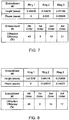
- FIGUREs 3-8 provide example multifocal embodiments for a (0, +1, +2, +3) diffractive lens wherein the +1 order is suppressed.
- This advantageously provides an intermediate focus at 2/3 of the near add power, corresponding respectively to a focused image at 60 cm and 40 cm distance.
- the diffraction efficiency for the distance vision (zero-order) focus can be nearly 40%, comparable to the diffraction efficiency for conventional bifocal lenses, and the diffraction efficiency for the suppressed first-order focus can be less than 5%, while still providing visible intermediate and near foci at normal working distances of 60 cm and 40 cm, respectively.
- this better approximates the full range of working vision that a patient would use in the absence of the presbyopic condition.
- the embodiments described herein are multifocal posterior chamber IOLs using (0, +1, +2, +3) diffractive orders with the +1 order being suppressed.
- This four-order embodiment could use different consecutive diffractive orders, such as starting with an order from -4 to -1, for example.
- the approach could be applied in principle to more than four diffractive orders; for example, a five-order diffractive lens could have add powers including two intermediate powers, a near power, and a suppressed intermediate power.
Abstract
Description
- The present invention relates generally to multifocal ophthalmic lenses and more specifically to a multifocal diffractive ophthalmic lens with a suppressed diffractive order.
- The human eye functions to provide vision by refracting light through a clear outer portion called the cornea, and refracting the light by way of a crystalline lens onto a retina. The quality of the focused image depends on many factors including the size and shape of the eye, and the transparency of the cornea and the lens. When age or disease causes the lens to become aberrated, vision deteriorates because of the loss of retinal image quality. This loss of optical quality in the lens of the eye is medically known as a cataract. An accepted treatment for this condition is surgical removal of the lens and replacement of the lens function by an artificial intraocular lens (IOL). As the eye ages, it may also lose the ability to change focus to nearer focal points, known as accommodation. This loss of accommodation with age is known as presbyopia.
- In the United States, the majority of cataractous lenses are removed by a surgical technique called phacoemulsification. During this procedure, a portion of the anterior capsule is removed and a thin phacoemulsification cutting tip is inserted into the diseased lens and vibrated ultrasonically. The vibrating cutting tip liquefies or emulsifies the nucleus and cortex of the lens so that the lens may be aspirated out of the eye. The diseased nucleus and cortex of the lens, once removed, is replaced by an artificial intraocular lens (IOL) in the remaining capsule (in-the-bag). In order to at least partially restore the patient's ability to see in focus at near distances, the implanted IOL may be a multifocal lens.
One common type of multifocal lens is a diffractive lens, such as a bifocal lens providing distance vision and near (or intermediate) vision. Trifocal diffractive lenses are also available that provide an additional focal point and, at least potentially, a broader range of in-focus vision. However, there are disadvantages associated with dividing light energy among multiple focal points, particularly in trifocal lenses. Thus, there remains a need for improved multifocal diffractive lenses. - The present invention provides a multifocal ophthalmic lens in accordance with claims which follow. In various embodiments of the invention, a multifocal ophthalmic lens includes an ophthalmic lens and a diffractive element. The ophthalmic lens has a base curvature corresponding to a base power. The diffractive element produces constructive interference in at least four consecutive diffractive orders corresponding a range of vision between near and distance vision. The constructive interference produces a near focus, a distance focus corresponding to the base power of the ophthalmic lens, and an intermediate focus between the near focus and the distance focus. A diffraction efficiency of at least one of the diffractive orders is suppressed to less than ten percent.
- Other features and advantages of various embodiments of the present invention will be apparent to one skilled in the art from the following description.
-
-
FIGURE 1 illustrates an intraocular lens according to particular embodiments of the present invention; -
FIGURE 2 illustrates a diffractive step arrangement according to particular embodiments of the present invention; and -
FIGURES 3-8 are tables illustrating particular diffractive step arrangements according to particular embodiments of the present invention. - Various embodiments of the present invention provide a multifocal diffractive ophthalmic lens with at least one suppressed diffractive order. By suppression of one diffractive order, the performance of the lens can be tailored relative to conventional diffractive lenses. Known trifocal diffractive lenses, for example, divide light between multiple diffractive foci, such as (-1, 0, +1) order foci or (0, +1, +2) order foci.
- By contrast, various embodiments of the present invention provide at least three foci corresponding to diffractive orders wherein at least one intermediate diffractive order is suppressed. This provides an intermediate focus that is closer either to distance vision or near vision, which provides a broader range of vision around the respective focus. Furthermore, suppression of the other intermediate order distributes more energy to the other foci, which may provide more useful vision. In the following description, the references to foci for an ophthalmic lens refer to a corresponding diffractive focus within the range of vision extending from ordinary near viewing around 30 cm to distance vision (essentially modeled as collinear light rays from infinite distance). This excludes spurious higher orders of diffractive lenses that lie outside the range of vision, which provide only unwanted light effects. Thus, for example, even diffractive lenses that are nominally bifocal include higher-order diffractive foci from constructive interference, but for purposes of this specification, those should not be considered foci of the ophthalmic lens.
- In other embodiments, a multifocal diffactive lens produces foci corresponding to at least four consecutive diffractive orders including at least one focus less than one half of the near-most add power and at least one other focus greater than one half of the nearmost add power. This may be advantageous over conventional trifocal lenses, which have an add power that is half of the nearmost add power. This intermediate vision corresponds to twice the near-vision distance, so that if the near add-power corresponds to a working distance of 40 cm, a conventional reading distance, the intermediate viewing distance would be 80 cm. Given that a common intermediate working distance is at 60 cm, this would not provide a sharp focus at the most common working distance, which would fall between the near and intermediate foci. By contrast, a lens with a focus corresponding to 2/3 of the near add power would provide a focus at 60 cm, corresponding to the intermediate working distance.
-
FIGURE 1 illustrates a particular embodiment of a multifocal diffractive ophthalmic lens (IOL) 100 including adiffractive element 102. Thediffractive element 102 comprises diffractive steps 104 (also known as zones) having a characteristic radial separation to produce constructive interference at characteristic foci. In principle, any diffractive element that produces constructive interference through phase shifting in interfering zones, often referred to as a hologram, can be adapted for use in such a multifocal diffractive ophthalmic lens. Also, while the diffractive element is depicted with annular zones, the zones could conceivably be partial, such as semicircular or sectored zones, as well. While the following description will concern adiffractive element 102 including annulardiffractive steps 103, it should be understood by those skilled in the art that suitable substitutions may be made in any embodiment discloses herein. - IOL 100 also includes an optic 104 on which the
diffractive element 102 is located. The optic 104 determines the base optical power of the lens, which typically corresponds to the distance vision of the patient. This need not always the case; for example, a non-dominant eye may have an IOL with a base optical power is slightly less than the corresponding distance power for the patient to improve overall binocular vision for both eyes. Regardless, the add power for the IOL can be defined with respect to the base optical power.Haptics 106 hold the IOL 100 in place, providing stable fixation within the capsular bag. Although haptic arms are illustrated in the example, any suitable haptics fixation structure for the capsular bag or the ciliary sulcus compatible with posterior chamber implantation could also be used in a posterior chamber IOL. - Although the example below deals with a
posterior chamber IOL 100, other ophthalmic lenses, including multifocal diffractive spectacles and multifocal diffractive contact lenses, could also benefit from the same approach. The known and fixed position of the lens relative to the optical axis makes such applications particularly advantageous for intraocular lenses, including intracorneal, anterior chamber, and posterior chamber lenses. However, this does not exclude the utility of multifocality in other applications. -
FIGURE 2 illustrates, in more detail, a diffractive step structure useful for ophthalmic lenses such as the IOL 100 ofFIGURE 1 . In particular,FIGURE 2 illustrates a three-step repeating diffractive structure that produces a phase relationship for constructive interference at four different focal points within the range of vision. The step relationship at consecutive radial step boundaries along a scaled radial axis (x-axis), measured in r2 -space, is as follows:
- The listed phase relationships are given with respect to the base curve determined by the base power of the IOL, corresponding to the zero-order diffractive focus for the lens. The radial spacing of the zones xi is ordinarily determined based on the ordinary Fresnel zone spacing in r2 -space as determined by the diffractive add power, although it can be varied to adjust the relative phase relationship between the components in ways known in the art to slightly modify the energy distribution between the foci. In the examples listed below, the spacing should be assumed to according to the known Fresnel pattern for producing four foci. This is analogous to the trifocal approach described in, e.g.,
U.S. Patents No. 5,344,447 and5,760,817 andPCT publication WO 2010/0093975 U.S. Patent No. 5,699,142 . -
FIGUREs 3-8 provide example multifocal embodiments for a (0, +1, +2, +3) diffractive lens wherein the +1 order is suppressed. This advantageously provides an intermediate focus at 2/3 of the near add power, corresponding respectively to a focused image at 60 cm and 40 cm distance. Notably, the diffraction efficiency for the distance vision (zero-order) focus can be nearly 40%, comparable to the diffraction efficiency for conventional bifocal lenses, and the diffraction efficiency for the suppressed first-order focus can be less than 5%, while still providing visible intermediate and near foci at normal working distances of 60 cm and 40 cm, respectively. Compared to conventional multifocals, this better approximates the full range of working vision that a patient would use in the absence of the presbyopic condition. - Although particular embodiments have been described herein, one skilled in the art will appreciate that numerous variations are possible. In particular, the embodiments described herein are multifocal posterior chamber IOLs using (0, +1, +2, +3) diffractive orders with the +1 order being suppressed. This four-order embodiment could use different consecutive diffractive orders, such as starting with an order from -4 to -1, for example. And while it is desirable for the zero-order to be included for distance vision, that condition is not a necessary constraint. Lastly, the approach could be applied in principle to more than four diffractive orders; for example, a five-order diffractive lens could have add powers including two intermediate powers, a near power, and a suppressed intermediate power.
- Further features of the specification are set out in accordance with the following numbered clauses.
- 1. A multifocal ophthalmic lens, comprising:
- an ophthalmic lens having a base curvature corresponding to a base power; and
- a diffractive element, the diffractive element producing constructive interference in at least four consecutive diffractive orders corresponding a range of vision between near and distance vision, wherein the constructive interference produces a near focus, a distance focus corresponding to the base power of the ophthalmic lens, and an intermediate focus between the near focus and the distance focus and wherein a diffraction efficiency of at least one of the diffractive orders is suppressed to less than ten percent.
- 2. The lens of
clause 1, wherein the lens is an intraocular lens (IOL). - 3. The lens of
clause 2, wherein the IOL is a posterior chamber IOL. - 4. The lens of
clause 3, wherein the posterior chamber IOL is configured to be implanted in a capsular bag. - 5. The lens of
clause 1, wherein the at least four consecutive orders are (0, +1, +2, +3). - 6. The lens of
clause 5, wherein the +1 order is suppressed. - 7. The lens of
clause 1, wherein the near focus corresponds to vision at 40 cm, and the intermediate focus corresponds to vision at 60 cm. - 8. The lens of
clause 1, wherein the diffractive element comprises a plurality of annular diffractive steps. - 9. The lens of
clause 1, wherein the diffractive steps have a corresponding step height relative to the base curvature of the ophthalmic lens at consecutive radial step boundaries as follows:
Claims (9)
- A multifocal ophthalmic lens, comprising:an ophthalmic lens having an anterior surface and a posterior surface;
anda diffractive element disposed on at least one of the anterior surface and the posterior surface, the diffractive element including a plurality of annular diffractive steps and four consecutive diffractive orders;wherein:the ophthalmic lens produces a near focus, an intermediate focus, and a distance focus each corresponding to a different one of the four consecutive diffractive orders; andthe plurality of annular diffractive steps of the diffractive element are configured such that one of the four diffractive orders is suppressed and at least a portion of the energy associated with that suppressed diffractive order is redistributed to one of the near focus, the intermediate focus, and the distance focus. - The lens of Claim1, wherein the lens is an intraocular lens (IOL).
- The lens of Claim 2, wherein the IOL is a posterior chamber IOL.
- The lens of Claim 3, wherein the posterior chamber IOL is configured to be implanted in a capsular bag.
- The lens of Claim 1, wherein:the four consecutive diffractive orders include a lowest diffractive order, a highest diffractive order, and two intermediate diffractive orders; andthe suppressed diffractive order is one of the two intermediate diffractive orders.
- The lens of Claim 1, wherein the four consecutive diffractive orders are (0, +1, +2, +3).
- The lens of Claim 6, wherein the suppressed diffractive order is the +1 diffractive order.
- The lens of Claim 7, wherein at least a portion of the energy associated with the +1 diffractive order is redistributed to the distance focus.
- The lens of Claim 1, wherein the near focus corresponds to vision at 40 cm, and the intermediate focus corresponds to vision at 60 cm.
Applications Claiming Priority (3)
| Application Number | Priority Date | Filing Date | Title |
|---|---|---|---|
| US201461993892P | 2014-05-15 | 2014-05-15 | |
| US14/575,333 US9335564B2 (en) | 2014-05-15 | 2014-12-18 | Multifocal diffractive ophthalmic lens using suppressed diffractive order |
| EP15152911.2A EP2945009B1 (en) | 2014-05-15 | 2015-01-28 | Multifocal diffractive ophthalmic lens having a suppressed diffractive order |
Related Parent Applications (1)
| Application Number | Title | Priority Date | Filing Date |
|---|---|---|---|
| EP15152911.2A Division EP2945009B1 (en) | 2014-05-15 | 2015-01-28 | Multifocal diffractive ophthalmic lens having a suppressed diffractive order |
Publications (1)
| Publication Number | Publication Date |
|---|---|
| EP3242154A1 true EP3242154A1 (en) | 2017-11-08 |
Family
ID=52440573
Family Applications (2)
| Application Number | Title | Priority Date | Filing Date |
|---|---|---|---|
| EP17176212.3A Pending EP3242154A1 (en) | 2014-05-15 | 2015-01-28 | Multifocal diffractive ophthalmic lens using suppressed diffractive order |
| EP15152911.2A Active EP2945009B1 (en) | 2014-05-15 | 2015-01-28 | Multifocal diffractive ophthalmic lens having a suppressed diffractive order |
Family Applications After (1)
| Application Number | Title | Priority Date | Filing Date |
|---|---|---|---|
| EP15152911.2A Active EP2945009B1 (en) | 2014-05-15 | 2015-01-28 | Multifocal diffractive ophthalmic lens having a suppressed diffractive order |
Country Status (18)
| Country | Link |
|---|---|
| US (4) | US9335564B2 (en) |
| EP (2) | EP3242154A1 (en) |
| JP (5) | JP6480203B2 (en) |
| KR (5) | KR102321958B1 (en) |
| CN (4) | CN113589552B (en) |
| AU (4) | AU2015200449B2 (en) |
| BR (1) | BR102015002219B1 (en) |
| CA (1) | CA2880365C (en) |
| DK (1) | DK2945009T3 (en) |
| ES (1) | ES2638603T3 (en) |
| MX (2) | MX358147B (en) |
| PH (1) | PH12015000040A1 (en) |
| PL (1) | PL2945009T3 (en) |
| PT (1) | PT2945009T (en) |
| RU (1) | RU2666172C2 (en) |
| SG (1) | SG10201500750RA (en) |
| TW (2) | TW201919549A (en) |
| ZA (1) | ZA201500710B (en) |
Families Citing this family (24)
| Publication number | Priority date | Publication date | Assignee | Title |
|---|---|---|---|---|
| CN108013952A (en) | 2012-08-31 | 2018-05-11 | Amo格罗宁根私人有限公司 | Polycyclic crystalline lens, system and method for extended focal depth |
| US11000366B2 (en) | 2014-05-15 | 2021-05-11 | Alcon Inc. | Multifocal diffractive ophthalmic lens |
| US9335564B2 (en) * | 2014-05-15 | 2016-05-10 | Novartis Ag | Multifocal diffractive ophthalmic lens using suppressed diffractive order |
| HUE038956T2 (en) * | 2015-10-02 | 2018-12-28 | Rayner Intraocular Lenses Ltd | Multifocal lens |
| US10568734B2 (en) * | 2016-03-03 | 2020-02-25 | Novartis Ag | Adjusting the apodization pattern for diffractive IOLs |
| KR102635338B1 (en) * | 2017-02-14 | 2024-02-07 | 데이브, 자그래트 나타바르 | Diffractive multifocal implantable lens device |
| EP3595584A1 (en) | 2017-03-17 | 2020-01-22 | AMO Groningen B.V. | Diffractive intraocular lenses for extended range of vision |
| US10420638B2 (en) | 2017-04-27 | 2019-09-24 | Novartis Ag | Multifocal ophthalmic lens having chromatic aberration correction |
| DE102017112085A1 (en) | 2017-06-01 | 2018-12-06 | Carl Zeiss Meditec Ag | Artificial eye lens with medicament depot formed therein and method for making an artificial eye lens |
| DE102017112086A1 (en) | 2017-06-01 | 2018-12-06 | Carl Zeiss Meditec Ag | Artificial eye lens with diffractive grating structure and method for producing an artificial eye lens |
| DE102017112087A1 (en) | 2017-06-01 | 2018-12-06 | Carl Zeiss Meditec Ag | Artificial eye lens with laser-generated birefringent structure and method for producing an artificial eye lens |
| US11523897B2 (en) | 2017-06-23 | 2022-12-13 | Amo Groningen B.V. | Intraocular lenses for presbyopia treatment |
| WO2019002390A1 (en) | 2017-06-28 | 2019-01-03 | Amo Groningen B.V. | Extended range and related intraocular lenses for presbyopia treatment |
| EP3646110A1 (en) | 2017-06-28 | 2020-05-06 | Amo Groningen B.V. | Diffractive lenses and related intraocular lenses for presbyopia treatment |
| US11327210B2 (en) | 2017-06-30 | 2022-05-10 | Amo Groningen B.V. | Non-repeating echelettes and related intraocular lenses for presbyopia treatment |
| CN108652789B (en) * | 2017-07-20 | 2020-04-21 | 东莞东阳光医疗智能器件研发有限公司 | Full-range diffractive intraocular lens with enhanced near vision |
| CN109725441A (en) * | 2017-10-28 | 2019-05-07 | 郑克立 | A kind of holographic glasses piece |
| DE202019005978U1 (en) * | 2018-09-13 | 2023-10-23 | Hanita Lenses R.C.A. | Multifocal intraocular lens |
| CN113194893A (en) * | 2018-10-18 | 2021-07-30 | 爱尔康公司 | Intraocular lens with extended depth of focus |
| US20220133469A1 (en) * | 2018-12-20 | 2022-05-05 | Aaren Scientific Inc. | Quint-focal diffractive intraocular lens |
| EP4085293A1 (en) | 2019-12-30 | 2022-11-09 | AMO Groningen B.V. | Achromatic lenses with zone order mixing for vision treatment |
| CA3166089A1 (en) | 2019-12-30 | 2021-07-08 | Amo Groningen B.V. | Achromatic lenses for vision treatment |
| WO2021136617A1 (en) | 2019-12-30 | 2021-07-08 | Amo Groningen B.V. | Lenses having diffractive profiles with irregular width for vision treatment |
| JP2024507815A (en) * | 2021-02-21 | 2024-02-21 | アールエックスサイト インコーポレイテッド | Composite light-accommodating intraocular lens with diffractive structure |
Citations (7)
| Publication number | Priority date | Publication date | Assignee | Title |
|---|---|---|---|---|
| WO1994011765A1 (en) * | 1992-11-12 | 1994-05-26 | Massachusetts Institute Of Technology | Diffractive trifocal intraocular lens design |
| EP0605841A1 (en) * | 1993-01-06 | 1994-07-13 | Holo-Or Ltd. | Diffractive multi-focal lens |
| US5699142A (en) | 1994-09-01 | 1997-12-16 | Alcon Laboratories, Inc. | Diffractive multifocal ophthalmic lens |
| US5760817A (en) | 1994-06-20 | 1998-06-02 | Hewlett-Packard Company | Laser printer with apparatus to reduce banding by servo adjustment of a scanned laser beam |
| WO2006023404A2 (en) * | 2004-08-20 | 2006-03-02 | Apollo Optical Systems, Inc. | Diffractive lenses for vision correction |
| WO2010093975A2 (en) | 2009-02-12 | 2010-08-19 | The Arizona Board Of Regents On Behalf Of The University Of Arizona | Diffractive trifocal lens |
| EP2377493A1 (en) * | 2009-01-06 | 2011-10-19 | Menicon Co., Ltd. | Method for manufacturing aphakic intraocular lens |
Family Cites Families (19)
| Publication number | Priority date | Publication date | Assignee | Title |
|---|---|---|---|---|
| JPS5342244B2 (en) * | 1973-12-10 | 1978-11-10 | ||
| EP0109753B1 (en) * | 1982-10-27 | 1988-07-27 | Pilkington Plc | Bifocal contact lens comprising a plurality of concentric zones |
| US20070171362A1 (en) * | 2004-12-01 | 2007-07-26 | Simpson Michael J | Truncated diffractive intraocular lenses |
| US7441894B2 (en) * | 2006-02-09 | 2008-10-28 | Alcon Manufacturing, Ltd. | Pseudo-accommodative IOL having diffractive zones with varying areas |
| US7481532B2 (en) * | 2006-02-09 | 2009-01-27 | Alcon, Inc. | Pseudo-accommodative IOL having multiple diffractive patterns |
| US20070258143A1 (en) * | 2006-05-08 | 2007-11-08 | Valdemar Portney | Aspheric multifocal diffractive ophthalmic lens |
| US7572007B2 (en) * | 2006-08-02 | 2009-08-11 | Alcon, Inc. | Apodized diffractive IOL with frustrated diffractive region |
| US8747466B2 (en) * | 2007-08-27 | 2014-06-10 | Amo Groningen, B.V. | Intraocular lens having extended depth of focus |
| CA2722274C (en) * | 2008-04-24 | 2018-10-02 | Amo Regional Holdings | Diffractive lens exhibiting enhanced optical performance |
| US8231219B2 (en) * | 2008-04-24 | 2012-07-31 | Amo Groningen B.V. | Diffractive lens exhibiting enhanced optical performance |
| US8734511B2 (en) * | 2008-10-20 | 2014-05-27 | Amo Groningen, B.V. | Multifocal intraocular lens |
| JP5460211B2 (en) * | 2009-09-29 | 2014-04-02 | 株式会社ニデック | Multifocal intraocular lens |
| CN102892381A (en) * | 2009-12-18 | 2013-01-23 | Amo格罗宁根私人有限公司 | Single microstructure lens, systems and methods |
| BE1019161A5 (en) * | 2010-01-26 | 2012-04-03 | Physiol | INTRAOCULAR LENS. |
| DE102010018436B4 (en) * | 2010-04-27 | 2017-02-09 | Carl Zeiss Meditec Ag | Multifocal eye lens |
| US20120140166A1 (en) * | 2010-12-07 | 2012-06-07 | Abbott Medical Optics Inc. | Pupil dependent diffractive lens for near, intermediate, and far vision |
| JP5916770B2 (en) * | 2012-02-09 | 2016-05-11 | 株式会社メニコン | Multifocal ophthalmic lens and manufacturing method thereof |
| US8678583B2 (en) * | 2012-05-09 | 2014-03-25 | Allen Louis Cohen | Trifocal IOL using diffraction |
| US9335564B2 (en) | 2014-05-15 | 2016-05-10 | Novartis Ag | Multifocal diffractive ophthalmic lens using suppressed diffractive order |
-
2014
- 2014-12-18 US US14/575,333 patent/US9335564B2/en active Active
-
2015
- 2015-01-28 PT PT151529112T patent/PT2945009T/en unknown
- 2015-01-28 PL PL15152911T patent/PL2945009T3/en unknown
- 2015-01-28 EP EP17176212.3A patent/EP3242154A1/en active Pending
- 2015-01-28 ES ES15152911.2T patent/ES2638603T3/en active Active
- 2015-01-28 EP EP15152911.2A patent/EP2945009B1/en active Active
- 2015-01-28 DK DK15152911.2T patent/DK2945009T3/en active
- 2015-01-29 CA CA2880365A patent/CA2880365C/en active Active
- 2015-01-30 RU RU2015103070A patent/RU2666172C2/en active
- 2015-01-30 TW TW108102942A patent/TW201919549A/en unknown
- 2015-01-30 CN CN202110921729.2A patent/CN113589552B/en active Active
- 2015-01-30 MX MX2015001436A patent/MX358147B/en active IP Right Grant
- 2015-01-30 SG SG10201500750RA patent/SG10201500750RA/en unknown
- 2015-01-30 MX MX2018009547A patent/MX2018009547A/en unknown
- 2015-01-30 AU AU2015200449A patent/AU2015200449B2/en active Active
- 2015-01-30 JP JP2015017495A patent/JP6480203B2/en active Active
- 2015-01-30 TW TW104103263A patent/TWI653034B/en not_active IP Right Cessation
- 2015-01-30 ZA ZA2015/00710A patent/ZA201500710B/en unknown
- 2015-01-30 PH PH12015000040A patent/PH12015000040A1/en unknown
- 2015-01-30 CN CN201510050430.9A patent/CN105093565B/en active Active
- 2015-01-30 BR BR102015002219-0A patent/BR102015002219B1/en active IP Right Grant
- 2015-01-30 CN CN202010044633.8A patent/CN111123553B/en active Active
- 2015-01-30 CN CN202311076087.6A patent/CN117055242A/en active Pending
- 2015-02-02 KR KR1020150016317A patent/KR102321958B1/en active IP Right Grant
-
2016
- 2016-04-11 US US15/095,253 patent/US10278811B2/en active Active
-
2019
- 2019-02-01 JP JP2019017340A patent/JP6792006B2/en active Active
- 2019-04-01 US US16/371,395 patent/US11000365B2/en active Active
- 2019-11-28 AU AU2019271990A patent/AU2019271990B2/en active Active
-
2020
- 2020-11-05 JP JP2020184866A patent/JP7080954B2/en active Active
-
2021
- 2021-04-09 US US17/226,302 patent/US20210228338A1/en active Pending
- 2021-08-25 AU AU2021221613A patent/AU2021221613B2/en active Active
- 2021-10-28 KR KR1020210145907A patent/KR102399466B1/en active IP Right Grant
-
2022
- 2022-05-13 KR KR1020220058677A patent/KR102496493B1/en active IP Right Grant
- 2022-05-25 JP JP2022084987A patent/JP7379591B2/en active Active
-
2023
- 2023-01-31 KR KR1020230012778A patent/KR102627429B1/en active IP Right Grant
- 2023-07-04 JP JP2023109915A patent/JP2023123797A/en active Pending
- 2023-07-19 AU AU2023206131A patent/AU2023206131A1/en active Pending
-
2024
- 2024-01-16 KR KR1020240006829A patent/KR20240011859A/en not_active Application Discontinuation
Patent Citations (8)
| Publication number | Priority date | Publication date | Assignee | Title |
|---|---|---|---|---|
| WO1994011765A1 (en) * | 1992-11-12 | 1994-05-26 | Massachusetts Institute Of Technology | Diffractive trifocal intraocular lens design |
| US5344447A (en) | 1992-11-12 | 1994-09-06 | Massachusetts Institute Of Technology | Diffractive trifocal intra-ocular lens design |
| EP0605841A1 (en) * | 1993-01-06 | 1994-07-13 | Holo-Or Ltd. | Diffractive multi-focal lens |
| US5760817A (en) | 1994-06-20 | 1998-06-02 | Hewlett-Packard Company | Laser printer with apparatus to reduce banding by servo adjustment of a scanned laser beam |
| US5699142A (en) | 1994-09-01 | 1997-12-16 | Alcon Laboratories, Inc. | Diffractive multifocal ophthalmic lens |
| WO2006023404A2 (en) * | 2004-08-20 | 2006-03-02 | Apollo Optical Systems, Inc. | Diffractive lenses for vision correction |
| EP2377493A1 (en) * | 2009-01-06 | 2011-10-19 | Menicon Co., Ltd. | Method for manufacturing aphakic intraocular lens |
| WO2010093975A2 (en) | 2009-02-12 | 2010-08-19 | The Arizona Board Of Regents On Behalf Of The University Of Arizona | Diffractive trifocal lens |
Also Published As
Similar Documents
| Publication | Publication Date | Title |
|---|---|---|
| US11000365B2 (en) | Multifocal diffractive ophthalmic lens using suppressed diffractive order | |
| US10285806B2 (en) | Multifocal diffractive ophthalmic lens | |
| US11000366B2 (en) | Multifocal diffractive ophthalmic lens | |
| US20210220120A1 (en) | Multifocal diffractive ophthalmic lens | |
| RU2783151C2 (en) | Multifocal diffraction ophthalmic lens using suppressed diffraction order | |
| BR122020014822B1 (en) | MULTIFOCAL OPHTHALMIC LENS |
Legal Events
| Date | Code | Title | Description |
|---|---|---|---|
| PUAI | Public reference made under article 153(3) epc to a published international application that has entered the european phase |
Free format text: ORIGINAL CODE: 0009012 |
|
| STAA | Information on the status of an ep patent application or granted ep patent |
Free format text: STATUS: THE APPLICATION HAS BEEN PUBLISHED |
|
| AC | Divisional application: reference to earlier application |
Ref document number: 2945009 Country of ref document: EP Kind code of ref document: P |
|
| AK | Designated contracting states |
Kind code of ref document: A1 Designated state(s): AL AT BE BG CH CY CZ DE DK EE ES FI FR GB GR HR HU IE IS IT LI LT LU LV MC MK MT NL NO PL PT RO RS SE SI SK SM TR |
|
| STAA | Information on the status of an ep patent application or granted ep patent |
Free format text: STATUS: REQUEST FOR EXAMINATION WAS MADE |
|
| 17P | Request for examination filed |
Effective date: 20180502 |
|
| RBV | Designated contracting states (corrected) |
Designated state(s): AL AT BE BG CH CY CZ DE DK EE ES FI FR GB GR HR HU IE IS IT LI LT LU LV MC MK MT NL NO PL PT RO RS SE SI SK SM TR |
|
| STAA | Information on the status of an ep patent application or granted ep patent |
Free format text: STATUS: EXAMINATION IS IN PROGRESS |
|
| 17Q | First examination report despatched |
Effective date: 20180622 |
|
| STAA | Information on the status of an ep patent application or granted ep patent |
Free format text: STATUS: EXAMINATION IS IN PROGRESS |
|
| RAP1 | Party data changed (applicant data changed or rights of an application transferred) |
Owner name: ALCON INC. |
|
| STAA | Information on the status of an ep patent application or granted ep patent |
Free format text: STATUS: EXAMINATION IS IN PROGRESS |
|
| P01 | Opt-out of the competence of the unified patent court (upc) registered |
Effective date: 20230507 |