EP3242084A1 - A combustor assembly with impingement plates for redirecting cooling air flow in gas turbine engines - Google Patents
A combustor assembly with impingement plates for redirecting cooling air flow in gas turbine engines Download PDFInfo
- Publication number
- EP3242084A1 EP3242084A1 EP16168429.5A EP16168429A EP3242084A1 EP 3242084 A1 EP3242084 A1 EP 3242084A1 EP 16168429 A EP16168429 A EP 16168429A EP 3242084 A1 EP3242084 A1 EP 3242084A1
- Authority
- EP
- European Patent Office
- Prior art keywords
- liner
- impingement
- sleeve
- combustion
- holes
- Prior art date
- Legal status (The legal status is an assumption and is not a legal conclusion. Google has not performed a legal analysis and makes no representation as to the accuracy of the status listed.)
- Withdrawn
Links
Images


Classifications
-
- F—MECHANICAL ENGINEERING; LIGHTING; HEATING; WEAPONS; BLASTING
- F23—COMBUSTION APPARATUS; COMBUSTION PROCESSES
- F23R—GENERATING COMBUSTION PRODUCTS OF HIGH PRESSURE OR HIGH VELOCITY, e.g. GAS-TURBINE COMBUSTION CHAMBERS
- F23R3/00—Continuous combustion chambers using liquid or gaseous fuel
- F23R3/002—Wall structures
-
- F—MECHANICAL ENGINEERING; LIGHTING; HEATING; WEAPONS; BLASTING
- F23—COMBUSTION APPARATUS; COMBUSTION PROCESSES
- F23R—GENERATING COMBUSTION PRODUCTS OF HIGH PRESSURE OR HIGH VELOCITY, e.g. GAS-TURBINE COMBUSTION CHAMBERS
- F23R3/00—Continuous combustion chambers using liquid or gaseous fuel
- F23R3/005—Combined with pressure or heat exchangers
-
- F—MECHANICAL ENGINEERING; LIGHTING; HEATING; WEAPONS; BLASTING
- F23—COMBUSTION APPARATUS; COMBUSTION PROCESSES
- F23R—GENERATING COMBUSTION PRODUCTS OF HIGH PRESSURE OR HIGH VELOCITY, e.g. GAS-TURBINE COMBUSTION CHAMBERS
- F23R3/00—Continuous combustion chambers using liquid or gaseous fuel
- F23R3/02—Continuous combustion chambers using liquid or gaseous fuel characterised by the air-flow or gas-flow configuration
- F23R3/04—Air inlet arrangements
- F23R3/06—Arrangement of apertures along the flame tube
-
- F—MECHANICAL ENGINEERING; LIGHTING; HEATING; WEAPONS; BLASTING
- F23—COMBUSTION APPARATUS; COMBUSTION PROCESSES
- F23R—GENERATING COMBUSTION PRODUCTS OF HIGH PRESSURE OR HIGH VELOCITY, e.g. GAS-TURBINE COMBUSTION CHAMBERS
- F23R3/00—Continuous combustion chambers using liquid or gaseous fuel
- F23R3/42—Continuous combustion chambers using liquid or gaseous fuel characterised by the arrangement or form of the flame tubes or combustion chambers
- F23R3/46—Combustion chambers comprising an annular arrangement of several essentially tubular flame tubes within a common annular casing or within individual casings
-
- F—MECHANICAL ENGINEERING; LIGHTING; HEATING; WEAPONS; BLASTING
- F23—COMBUSTION APPARATUS; COMBUSTION PROCESSES
- F23R—GENERATING COMBUSTION PRODUCTS OF HIGH PRESSURE OR HIGH VELOCITY, e.g. GAS-TURBINE COMBUSTION CHAMBERS
- F23R3/00—Continuous combustion chambers using liquid or gaseous fuel
- F23R3/42—Continuous combustion chambers using liquid or gaseous fuel characterised by the arrangement or form of the flame tubes or combustion chambers
- F23R3/50—Combustion chambers comprising an annular flame tube within an annular casing
-
- F—MECHANICAL ENGINEERING; LIGHTING; HEATING; WEAPONS; BLASTING
- F23—COMBUSTION APPARATUS; COMBUSTION PROCESSES
- F23R—GENERATING COMBUSTION PRODUCTS OF HIGH PRESSURE OR HIGH VELOCITY, e.g. GAS-TURBINE COMBUSTION CHAMBERS
- F23R2900/00—Special features of, or arrangements for continuous combustion chambers; Combustion processes therefor
- F23R2900/03041—Effusion cooled combustion chamber walls or domes
-
- F—MECHANICAL ENGINEERING; LIGHTING; HEATING; WEAPONS; BLASTING
- F23—COMBUSTION APPARATUS; COMBUSTION PROCESSES
- F23R—GENERATING COMBUSTION PRODUCTS OF HIGH PRESSURE OR HIGH VELOCITY, e.g. GAS-TURBINE COMBUSTION CHAMBERS
- F23R2900/00—Special features of, or arrangements for continuous combustion chambers; Combustion processes therefor
- F23R2900/03043—Convection cooled combustion chamber walls with means for guiding the cooling air flow
-
- F—MECHANICAL ENGINEERING; LIGHTING; HEATING; WEAPONS; BLASTING
- F23—COMBUSTION APPARATUS; COMBUSTION PROCESSES
- F23R—GENERATING COMBUSTION PRODUCTS OF HIGH PRESSURE OR HIGH VELOCITY, e.g. GAS-TURBINE COMBUSTION CHAMBERS
- F23R2900/00—Special features of, or arrangements for continuous combustion chambers; Combustion processes therefor
- F23R2900/03044—Impingement cooled combustion chamber walls or subassemblies
-
- F—MECHANICAL ENGINEERING; LIGHTING; HEATING; WEAPONS; BLASTING
- F23—COMBUSTION APPARATUS; COMBUSTION PROCESSES
- F23R—GENERATING COMBUSTION PRODUCTS OF HIGH PRESSURE OR HIGH VELOCITY, e.g. GAS-TURBINE COMBUSTION CHAMBERS
- F23R2900/00—Special features of, or arrangements for continuous combustion chambers; Combustion processes therefor
- F23R2900/03045—Convection cooled combustion chamber walls provided with turbolators or means for creating turbulences to increase cooling
Definitions
- the present invention relates to gas turbines, and more particularly to combustor assemblies for redirecting cooling air flow in gas turbine engines.
- cooling air for cooling of gas turbine components is a constant challenge and an important area of interest in gas turbine engine designs.
- conventional design uses many impingement holes spread in a large area of a cooling air channel wall or plate, such as a conventional burner plenum surface, overhanging or in close vicinity of the target surface.
- the cooling air emerges from the impingement holes in form of impingement jets and flows towards a target surface, for example a combustor liner surface, which is to be cooled in order to impact the target surface normally. It is important to have an adequate velocity in the impingement jets in order for the cooling air to reach the target surface and thus to cool the target surface.
- the impingement jets delivering the cooling air to downstream sections of the combustion liner surface are subjected to strong cross flow resulting from the cooling air that has entered through the impingement jets delivering the cooling air to upstream sections of the target surface and then flowing across the longitudinally extended target surface from the upstream section to the downstream section of the longitudinally extended target surface.
- the cross-flow affects the impingement jets delivering cooling air to the downstream sections of the combustion liner surface.
- the substantially normal flow of the cooling air in the impingement jets towards the target surface is disturbed by the cross flowing cooling air which flows substantially parallel to the target surface and as a result the impingement jets delivering cooling air to the downstream sections of the target surface may not impinge on the target surface especially in the downstream sections of the longitudinally extended target surface.
- the disturbance to the impingement jets as a result of the cross flow is increased as the cross flow gains more and more volume from the impingement jets received by the cross flow as the cross flow travels from the upstream section of the target surface to the downstream section of the target surface. Therefore, an improvement in cooling air flow in a combustor is desired.
- the object of the present disclosure is to provide a combustor assembly for a gas turbine engine that minimizes the disturbances due to the cross flow of the cooling air over longitudinally extended target surfaces such as a combustor liner surface that are to be cooled by impingement jets.
- the present technique presents a combustor assembly for a gas turbine engine.
- the combustor assembly includes a combustion liner, a flow sleeve, a casing and a plurality of impingement plates.
- the combustion liner has a longitudinal axis and defines or contains within itself a combustion chamber.
- the combustion liner has an inner surface that faces the combustion chamber and an outer surface opposite to the inner surface.
- the flow sleeve houses the combustion liner.
- the flow sleeve has an inner side and an outer side. The inner side faces the combustion liner and the outer side is opposite to the inner side of the flow sleeve.
- the combustion liner and the flow sleeve are coaxially aligned with respect to the longitudinal axis of the combustion liner and spaced apart radially to form an annular flow path between the outer surface of the combustion liner and the inner side of the flow sleeve.
- the combustor casing houses the flow sleeve and the combustion liner that is housed within the flow sleeve.
- the plurality of impingement plates are serially arranged longitudinally within the annular flow path.
- Each impingement plate has a sleeve part, a central plate and a liner part arranged serially along the flow direction of cooling air when flowing through the annular flow path.
- the liner part is connected to the outer surface of the combustion liner and the sleeve part is connected to the inner side of the flow sleeve.
- the central plate is in-between the liner part and the sleeve part.
- the central plate is suspended in the annular flow path by the liner part and the sleeve part such that the central plate is coaxially arranged with the combustion liner and the flow sleeve.
- Each impingement plate defines within the annular flow path in a radial direction with respect to the longitudinal axis a liner compartment and a sleeve compartment corresponding to said impingement plate.
- the central plate includes impingement holes.
- the cooling air that enters the annular flow path flows within the annular flow path from the sleeve compartment of one impingement plate, flowing through the impingement holes of said impingement plate as impingement jets towards the outer surface of the combustion liner, to the liner compartment of said impingement plate and therefrom to the sleeve compartment of a subsequent impingement plate. From the sleeve compartment of the subsequent impingement plate the cooling air flows through the impingement holes of said subsequent impingement plate as impingement jets towards the outer surface of the combustion liner and thus into the liner compartment of said subsequent impingement plate and therefrom to the sleeve compartment of a next subsequent impingement plate.
- a sleeve segment of a first impingement plate fluidly connected to a liner segment of the first impingement plate which in turn is fluidly connected to a sleeve segment of a second impingement plate which in turn is fluidly connected to a liner segment of the second impingement plate which in turn is fluidly connected to a sleeve segment of a third impingement plate and so on and so forth.
- the entire volume of the cooling air is used to serially cool each of the different sections on the combustion liner serially created by the different impingement plates, and thus less cooling air is required to cool the combustion liner.
- This is especially advantageous in combustors, such as co-flow combustors, where an air intake into the gas turbine engine is divided into combustion air and cooling air, because a greater percentage of the air intake can be used as combustion air.
- the impingement plates are arranged such that the cooling air is adapted to flow within the annular flow path in a direction same as a direction of flow of hot gas in the combustion chamber.
- a net flow direction of the cooling air within the annular flow path is defined by the arrangement of the impingement plates.
- this embodiment of the combustor assembly is especially suitable to be integrated in a co-flow combustor.
- the impingement plates are arranged such that the cooling air is adapted to flow within the annular flow path in a direction opposite to a direction of flow of hot gas in the combustion chamber.
- a net flow direction of the cooling air within the annular flow path is defined by the arrangement of the impingement plates.
- this embodiment of the combustor assembly is especially suitable to be integrated in a reverse flow combustor.
- the combustor casing and the flow sleeve are radially spaced apart to form a plenum between the outer side of the flow sleeve and the combustor casing.
- the plenum receives the cooling air from a diffuser, positioned separately and outside of the combustor assembly, and provides the cooling air to the annular flow path. This defines a way of integrating the combustor assembly in conventional gas turbine engines that include a diffuser downstream of their compressors.
- the flow sleeve includes one or more inlet holes adapted to allow a part of the cooling air from the plenum to enter one or more sleeve compartments corresponding to one or more impingement plates.
- the reduction in temperature occurs because cooler air admitted by the inlet holes directly from the plenum dilutes the cooling air coming from liner segment of the upstream impingement plates, where the cooling air coming from liner segment of the upstream impingement plates has a higher temperature as a result of its interaction with the outer surface of the combustion liner that is hot during operation of the gas turbine engine.
- the combustor liner includes a plurality of small liner holes corresponding to at least one impingement plate. Size of each of the small liner holes is lesser than a size of each of the impingement holes and wherein the small liner holes allow a part of the cooling air from the liner compartment corresponding to said impingement plate to enter the combustion chamber. The part of the cooling air flowing into the combustion chamber from the liner compartment through the small liner holes provides combustion acoustic damping and film cooling for the inner surface of the combustion liner.
- the combustor liner includes one or more big liner holes corresponding to at least one impingement plate. Size of each of the big liner holes is larger than a size of each of the impingement holes.
- the big liner holes allow a part of the cooling air from the liner compartment corresponding to said impingement plate to enter the combustion chamber. The part of the cooling air flowing into the combustion chamber from the liner compartment through the big liner holes mixes with the combustion gas or the working gas and reduces temperature of the combustion gas.
- the impingement holes are located in the central plate as an array spanning between the liner part and the sleeve part.
- portion of the outer surface of the combustion liner positioned directly beneath the entire expanse of the central plate is provided with impingement jets for cooling.
- the impingement holes are located in the central plate as an array limited to a portion of the central plate.
- portion of the outer surface of the combustion liner positioned directly beneath the portion of the central plate having the array of impingement holes is provided with impingement jets for cooling.
- the combustor assembly includes an array of turbulators positioned on the outer surface of the combustion liner.
- the turbulators increase the turbulence in the cooling air when passing over the outer surface of the combustion liner having the turbulators and this enhances cooling effect of the cooling air by reducing formation of laminar flows in the cooling air passing through the annular flow path of the combustor assembly.
- a shape of the turbulator is one of rib shaped, split-rib shaped, wedge shaped, split-wedge shaped, pin fin shaped, conical shaped, conical frustum shaped, spherical dome shaped, tetrahedron shaped, tetrahedral frustum shaped, pyramidal shaped, and pyramidal frustum shaped. This provides different shapes of the turbulators that may be used in fabricating the combustor assembly of the present technique.
- the outer surface of the combustion liner is segmented into serially arranged adjacent parts as a result of the serially arranged impingement plates.
- Each part of these serially arranged adjacent parts corresponds to one impingement plate and has a turbulated segment and a non-turbulated segment.
- the turbulated segment has one or more turbulators positioned on the outer surface of the combustion liner limited within the turbulated segment.
- the non-turbulated segment is devoid of turbulators. All the impingement holes of the one impingement plate are limited to a region of the central plate of the one impingement plate.
- the one impingement plate is positioned such that the region of the central plate when viewed along the radial direction is suspended directly above the non-turbulated segment and distinct from the turbulated segment.
- the cooling air when flowing from the sleeve segment to the liner segment of the one impingement plate forms impingement jets that impinge on the non-turbulated segment of the part of the outer surface corresponding to the one impingement plate, and then flows over the turbulated segment of the part of the outer surface corresponding to the one impingement plate before flowing to the sleeve segment of a subsequent impingement plate.
- a turbulent flow is maintained in the cooling air throughout the annular flow path.
- the combustion chamber is one of a can type combustion chamber, a cannular type combustion chamber and an annular type combustion chamber.
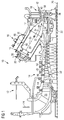
- FIG. 1 shows an example of a gas turbine engine 10 in a sectional view.
- the gas turbine engine 10 comprises, in flow series, an inlet 12, a compressor or compressor section 14, a combustor section 16 and a turbine section 18 which are generally arranged in flow series and generally about and in the direction of a rotational axis 20.
- the gas turbine engine 10 further comprises a shaft 22 which is rotatable about the rotational axis 20 and which extends longitudinally through the gas turbine engine 10.
- the shaft 22 drivingly connects the turbine section 18 to the compressor section 14.
- air 24 which is taken in through the air inlet 12 is compressed by the compressor section 14 and delivered to the combustion section or burner section 16.
- the burner section 16 comprises a burner plenum 26, one or more combustion chambers 28 extending along a longitudinal axis 35 and at least one burner 30 fixed to each combustion chamber 28.
- the combustion chambers 28 and the burners 30 are located inside the burner plenum 26.
- the compressed air passing through the compressor 14 enters a diffuser 32 and is discharged from the diffuser 32 into the burner plenum 26 from where a portion of the air enters the burner 30 and is mixed with a gaseous or liquid fuel.
- the air/fuel mixture is then burned and the combustion gas 34 or working gas from the combustion is channelled through the combustion chamber 28 to the turbine section 18 via a transition duct 17.
- This exemplary gas turbine engine 10 has a cannular combustor section arrangement 16, which is constituted by an annular array of combustor cans 19 each having the burner 30 and the combustion chamber 28, the transition duct 17 has a generally circular inlet that interfaces with the combustor chamber 28 and an outlet in the form of an annular segment.
- An annular array of transition duct outlets form an annulus for channelling the combustion gases to the turbine 18.
- the turbine section 18 comprises a number of blade carrying discs 36 attached to the shaft 22.
- two discs 36 each carry an annular array of turbine blades 38.
- the number of blade carrying discs could be different, i.e. only one disc or more than two discs.
- guiding vanes 40 which are fixed to a stator 42 of the gas turbine engine 10, are disposed between the stages of annular arrays of turbine blades 38. Between the exit of the combustion chamber 28 and the leading turbine blades 38 inlet guiding vanes 44 are provided and turn the flow of working gas onto the turbine blades 38.
- the combustion gas 34 from the combustion chamber 28 enters the turbine section 18 and drives the turbine blades 38 which in turn rotate the shaft 22.
- the guiding vanes 40, 44 serve to optimise the angle of the combustion or working gas 34 on the turbine blades 38.
- the turbine section 18 drives the compressor section 14.
- the compressor section 14 comprises an axial series of vane stages 46 and rotor blade stages 48.
- the rotor blade stages 48 comprise a rotor disc supporting an annular array of blades.
- the compressor section 14 also comprises a casing 50 that surrounds the rotor stages and supports the vane stages 48.
- the guide vane stages include an annular array of radially extending vanes that are mounted to the casing 50. The vanes are provided to present gas flow at an optimal angle for the blades at a given engine operational point.
- Some of the guide vane stages have variable vanes, where the angle of the vanes, about their own longitudinal axis, can be adjusted for angle according to air flow characteristics that can occur at different engine operations conditions.
- the casing 50 defines a radially outer surface 52 of the passage 56 of the compressor 14.
- a radially inner surface 54 of the passage 56 is at least partly defined by a rotor drum 53 of the rotor which is partly defined by the annular array of blades 48.
- the present technique is described with reference to the above exemplary turbine engine having a single shaft or spool connecting a single, multi-stage compressor and a single, one or more stage turbine.
- the present technique is equally applicable to two or three shaft engines and which can be used for industrial, aero or marine applications.
- the cannular combustor section arrangement 16 is also used for exemplary purposes and it should be appreciated that the present technique is equally applicable to annular type and can type combustion chambers.
- upstream and downstream refer to the flow direction of the airflow and/or working gas flow 34 through the engine unless otherwise stated.
- forward and rearward refer to the general flow of gas through the engine.
- axial, radial and circumferential are made with reference to the rotational axis 20 of the engine, unless otherwise stated.
- the basic idea of the invention is to segment the flow path of the cooling air in such a way that development of cross flows is at least partially obviated.
- the cooling air is effectively used i.e. for example less air is required for cooling and thus more air is available for combustion which in turn increases engine efficiency.
- FIGs 2 and 3 in combination with FIG 1 , two exemplary embodiments of a combustor assembly 1 according to the present technique have been described hereinafter.
- the combustor assembly 1 is to be integrated or implemented in the burner section or combustor section 16 of the gas turbine engine 10 of FIG 1 .
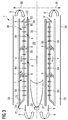
- FIG 2 schematically illustrates an embodiment of the combustor assembly 1 illustrating a co-flow design whereas FIG 3 schematically illustrates another embodiment of the combustor assembly 1 illustrating a reverse flow design.
- the combustor assembly 1 includes a combustion liner 60.
- the combustion liner 60 hereinafter also referred to as the liner 60, has a longitudinal axis 35 and defines or encloses a combustion chamber 28.
- the combustion reaction in the combustor section 16 occurs in the combustion chamber 28.
- position of a flame has been schematically represented by reference numeral 31 within the combustion chamber 28.
- the liner 60 has an inner surface 64 and an outer surface 62.
- the inner surface 64 forms the boundary of the combustion chamber 28 or in other words the inner surface 64 of the liner 60 faces the combustion chamber 28 or the longitudinal axis 35.
- the outer surface 62 is a surface opposite to the inner surface 64 i.e. the outer surface 62 faces away from the combustion chamber 28.
- the combustor assembly 1, hereinafter also referred to as the assembly 1, also includes a flow sleeve 70.
- the flow sleeve 70 hereinafter also referred to as the sleeve 70, houses or holds or accommodates the liner 60.
- the liner 60 in cannular combustors, as well as in the can type combustors, the liner 60 as well as the sleeve 70 are substantially cylindrical.
- the sleeve 70 has an inner side 72 and an outer side 74.
- the inner side 72 is the surface of the sleeve 70 facing the liner 60 i.e. facing the longitudinal axis 35.
- the outer side 74 is the surface of the sleeve 70 opposite to the inner side 72 i.e. the outer side 74 faces away from the liner 60 and also the longitudinal axis 35.
- the liner 60 and the sleeve 70 are coaxially aligned about the longitudinal axis 35 but are radially spaced apart, i.e. in a direction 99 radial to the longitudinal axis 35, to create an annular flow path 2 between the outer surface 62 of the liner 60 and the inner side 72 of the sleeve 70.
- the assembly 1 also includes a combustor casing 90.
- the combustor casing 90 hereinafter also referred to as the casing 90, houses or holds or accommodates the sleeve 70 and the liner 60 that is already housed within the sleeve 70.
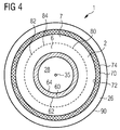
- FIG 4 schematically depicts a scheme of arrangement of the liner 60, the sleeve 70, the casing 90 and the annular flow path 2 for the cannular combustor section 16 of the gas turbine engine 1, hereinafter also referred to as the engine 1.
- FIG 4 schematically illustrates a view of the assembly 1 of FIGs 2 and 3 when viewed in a direction same as the longitudinal axis 35.
- the assembly 1 further includes a plurality of impingement plates 80.
- the impingement plates 80 are serially arranged longitudinally within the annular flow path 2, i.e. along a direction substantially parallel to the longitudinal axis 35.
- the impingement plates 80 are ring shaped or annular ring shaped and completely encircle the liner 60 spanning the entire annular flow path 2 as depicted in FIG 4 . It may be noted that in figures other than FIG 4 , only parts or sections of the impingement plates 80 have been schematically depicted although the impingement plates 80 have an annular shape.
- FIGs 2 and 3 represent cross-sectional views of the assembly 1 which has three impingement plates 80 serially arranges coaxially about the longitudinal axis 35 and spanning different sections of the annular flow path 2.
- the three impingement plates 80 depicted in FIGs 2 and 3 are only for exemplary purposes and the assembly 1 may include impingement plates 80 which are more than or less than three.
- each impingement plate 80 includes a liner part 86, a sleeve part 87 and a central plate 82 structurally in-between the liner part 86 and the sleeve part 87.
- the liner part 86 is connected to the outer surface 62 of the liner 60 and the sleeve part 87 is connected to the inner side 72 of the sleeve 70.
- the liner part 86 and the sleeve part 87 may be connected or joint or fixedly attached to the liner 60 and the sleeve 70, respectively, and may even be connected or positioned by interference fit.
- the central plate 82 between the liner part 86 and the sleeve part 87 is suspended in the annular flow path 2 coaxially with the liner 60 and the sleeve 70.
- FIG 4 spatial arrangement of the central plate 82 within the annular flow path 2 is depicted for embodiments of FIGs 2 and 3 of the assembly 1.
- each impingement plate 80 divides a section of the path 2 and thus defines within the path 2, in the radial direction 99, a liner compartment 6 and a sleeve compartment 7.
- one liner compartment 6 and one sleeve compartment 7 are created by each of the impingement plates 80 and are said to be corresponding to the impingement plate 80 that creates said liner compartment 6 and said sleeve compartment 7.
- the central plate 82 includes impingement holes 84 arranged in an array 85.
- the impingement holes 84 are depicted by arrows marked 84.
- the cooling air that enters the path 2 flows within the path 2 from the sleeve compartment 7 of one impingement plate 80 through the impingement holes 84 of that impingement plate 80 to the liner compartment 6 of that impingement plate 80.
- the cooling air flows, as shown by arrow 9, to the sleeve compartment 7 of a subsequent impingement plate 80 and further goes through the impingement holes 84 of the subsequent impingement plate 80 into the liner compartment of the subsequent impingement plate 80.
- the expression 'liner compartment 6 of the impingement plate 80' means liner compartment 6 corresponding to that impingement plate 80 as a result of which that liner compartment 6 has been created.
- the expression 'sleeve compartment 7 of the impingement plate 80' means sleeve compartment 7 corresponding to that impingement plate 80 as a result of which that sleeve compartment 7 has been created.
- the impingement plates 80 may be arranged such that the cooling air is adapted to flow within the path 2 in a direction 3 same as a direction 5 of flow of hot gas or working gas 34 (shown in FIG 1 ) in the combustion chamber 28 and out of combustion chamber 28 into the transition duct 17 of FIG 1 .
- the impingement plates 80 are arranged such that each impingement plate 80 is aligned in the path 2 longitudinally such that from an entrance of the path 2, that is an entrance where the cooling air first enters the path 2, for each impingement plate 80, first comes the liner part 6, then the central part 82 and then the sleeve part 7.
- a net flow direction, represented the direction 3 of the cooling air within the path 2 is defined by the arrangement of the impingement plates 80 within the path 2.
- the impingement plates 80 are arranged such that the cooling air is adapted to flow within the path 2 in a direction 4 opposite to the direction 5 of flow of working gas 34.
- the impingement plates 80 are arranged such that each impingement plate 80 is aligned in the path 2 longitudinally such that from an entrance of the path 2, that is an entrance where the cooling air first enters the path 2 and which is on opposite side of the path 2 in FIG 3 as compared to its location in FIG 2 , for each impingement plate 80, first comes the liner part 6, then the central part 82 and then the sleeve part 7.
- a net flow direction, represented the direction 4 of the cooling air within the path 2 is defined by the arrangement of the impingement plates 80 within the path 2.
- each impingement plate 80 first comes the liner part 6, then the central part 82 and then the sleeve part 7 within the path 2 and viewing from a point from where the cooling air enters the path 2.
- the casing 90 and the sleeve 70 are radially spaced apart to form a plenum 26 formed between the outer side 74 of the sleeve 70 and the casing 90.
- the plenum 26 receives the cooling air from a diffuser 32, as shown in FIG 1 and then provides the cooling air to the path 2.
- the position at which the cooling air enters the path 2 from the plenum 26 is the entry point of the cooling air into path 2.
- the cooling air may also be fed into the path 2 without coming through the plenum 26.
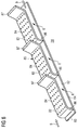
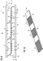
- FIG 5 schematically illustrates a perspective view of a part of the assembly 1 of FIG 3
- FIG 6 schematically illustrates a perspective view of a part of the combustor assembly of FIG 2 with the sleeve 70 removed to depict inside of the path 2 with the impingement plates 80 arranged serially.
- the sleeve 70 includes one or more inlet holes 75, depicted by arrows marked 75 in FIG 9 .
- the inlet holes 75 allow a part of the cooling air from the plenum 26 to enter one or more sleeve compartments 7 corresponding to one or more impingement plates 80.
- FIG 9 depicts addition of the cooling air through the inlet holes 75 into the sleeve compartments 7 of the impingement plates 80 that are arranged second and third after the first impingement plate 80, i.e. the impingement plates 80 arranged downstream with respect to the direction 9 of the first impingement plate 80.
- the inlet holes 75 may be, but not limited to, 2 mm (millimeter) to 5 mm in diameter.
- the liner 70 includes a plurality of small liner holes 66, depicted by arrows marked 66 in FIG 9 , corresponding to at least one impingement plate 80.
- the small liner holes 66 are shown to be in the liner 60 corresponding to liner compartment 6 of the impingement plates 80 at third position i.e. arranged downstream with respect to the direction 9 of the first impingement plate 80. Size of each of the small liner holes 66 is lesser than a size of each of the impingement holes 84.
- the small liner holes 66 may be between 1 mm to 2 mm in diameter and are smaller compared to the impingement holes 84 which may be 3 mm to 5 mm in diameter.
- the small liner holes 66 allow a part of the cooling air from the liner compartment 6 corresponding to said impingement plate 80 to enter the combustion chamber 28.
- the part of the cooling air flowing into the combustion chamber 28 from the liner compartment 6 through the small liner holes 66 provides combustion acoustic damping and film cooling for the inner surface 64 of the liner 60.
- the liner 60 includes one or more big liner holes 68, depicted by arrows marked 68 in FIG 9 , corresponding to at least one impingement plate 80.
- the big liner hole 68 is shown to be in the liner 60 corresponding to liner compartment 6 of the impingement plates 80 at first position. Size of each of the big liner holes 68 is larger than the size of each of the impingement holes 84.
- the big liner hole 68 may be between 10 mm to 20 mm in diameter and are larger compared to the impingement holes 84 which may be 3 mm to 5 mm in diameter.
- the big liner holes 68 allow a part of the cooling air from the liner compartment 6 corresponding to said impingement plate 80 to enter the combustion chamber 28.
- the part of the cooling air flowing into the combustion chamber 28 from the liner compartment 6 through the big liner holes 68 mixes with the combustion gas 34 (shown in FIG 1 ) and reduces temperature of the combustion gas 34.
- the impingement holes 84 are located as the array 85.
- the array 85 may span entire area of the central plate 82 between the liner part 86 and the sleeve part 87, as shown in FIG 7 , and as a result portion of the outer surface 62 of the liner 60 of FIGs 2 and 3 positioned directly beneath the entire expanse of the central plate 82 is provided with impingement jets for cooling.
- the array 85 may not span the entire expanse of the central plate 82 and may be limited to a portion of the central plate 82 for example a region 88 of the central plate 82 and may provide impingement jets to only that portion of the outer surface 62 of the liner 60 that is positioned directly beneath the region 88 of the central plate 82.
- the assembly 1 includes an array 67 of turbulators 65 positioned on the outer surface 62 of the liner 60.
- the turbulators 65 increase the turbulence in the cooling air when the cooling air passes over the outer surface 62 having the turbulators 65.
- the turbulators 65 depicted in FIGs 10 to 12 are rib shaped. However, it may be noted that it is well within the scope of the present technique, that the turbulators 65 may have variety of different shapes, for example but not limited to split-rib shaped i.e. rib shapes that are split longitudinally i.e.
- FIG 10 depicts the turbulators 65 to be limited to certain parts of the outer surface 82 of the liner 60, however, the turbulators 65 may be present over the entire expanse of the outer surface 62 within the path 2.
- FIG 10 depicts the turbulators 65 arranged in the arrays 67 on the liner 60 without other parts of the assembly 1 for purposes of explanation.
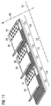
- FIG 11 shows the impingement plates 80 that have been now positioned on the liner 60 of FIG 10 .
- the outer surface 62 of the liner 60 is segmented into serially arranged adjacent parts 100 as a result of the serially arranged impingement plates 80.
- Three such parts 100 created as a result of placing three impingement plates 80 have been depicted in the example of FIG 11 .
- Each part 100 corresponds to one impingement plate 80.
- Each part 100 has a turbulated segment 101 and a non-turbulated segment 102.
- the turbulated segment 101 has one or more turbulators 65 positioned on the outer surface 62 of the liner 60.
- the non-turbulated segment 102 is devoid of turbulators 65.
- Either of the embodiments of the impingement plates 80 of FIGs 7 or 8 may be positioned in the assembly 1 with turbulators 65, however, for example of FIG 11 , the embodiment of the impingement plate 80 of FIG 8 has been used, solely for exemplary purpose. All the impingement holes 84 are limited to the region 88 of the central plate 82 in each impingement plate 80.
- the impingement plates 80 are positioned such that the region 88 of the central plate 82 when viewed along the radial direction 99 is suspended directly above the non-turbulated segment 102 and distinct from, i.e. non-overlaying, the turbulated segment 101.
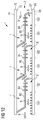
- FIG 12 depicts schematically air flow within a part of an exemplary embodiment of the assembly 1 having the turbulators 65 of FIGs 10 and 11 .
- the cooling air when flowing from the sleeve segment 7 to the liner segment 6 of the corresponding impingement plates 80 forms impingement jets that impinge on the non-turbulated segment 102 of the part 100 corresponding to the impingement plate 80.
- the cooling air then flows from the non-turbulated segment 102 to the turbulated segment 101 and then over the turbulated segment 101 of the part 100.
Abstract
A combustor assembly includes a combustion liner having a longitudinal axis and defining a combustion chamber, a flow sleeve housing the combustor liner, a casing housing the flow sleeve, and a plurality of impingement plates. The combustion liner and the flow sleeve are coaxially aligned and spaced apart radially forming an annular flow path within which the impingement plates are serially arranged longitudinally. Each impingement plate has a sleeve part connected to the flow sleeve, a liner part connected to the combustion liner and a central plate suspended in the annular flow path, coaxially arranged with the combustion liner, and including impingement holes. Each impingement plate defines a liner compartment and a sleeve compartment. Within the annular flow path, cooling air flows from the sleeve compartment, through the impingement holes and to the liner compartment of one impingement plate and therefrom to the sleeve compartment of a subsequent impingement plate.
Description
- The present invention relates to gas turbines, and more particularly to combustor assemblies for redirecting cooling air flow in gas turbine engines.
- To effectively use cooling air for cooling of gas turbine components is a constant challenge and an important area of interest in gas turbine engine designs. For example, for combustor liner cooling, conventional design uses many impingement holes spread in a large area of a cooling air channel wall or plate, such as a conventional burner plenum surface, overhanging or in close vicinity of the target surface. The cooling air emerges from the impingement holes in form of impingement jets and flows towards a target surface, for example a combustor liner surface, which is to be cooled in order to impact the target surface normally. It is important to have an adequate velocity in the impingement jets in order for the cooling air to reach the target surface and thus to cool the target surface. Therefore to achieve adequately high velocity in the impingement jets, size of the impingement holes is required to be small but concentration of impingement holes in a given area is high to ensure adequate volume of the cooling air is available to the target surface. However, since most of the target surfaces, especially combustion liner surface, are longitudinally extended, the impingement jets delivering the cooling air to downstream sections of the combustion liner surface are subjected to strong cross flow resulting from the cooling air that has entered through the impingement jets delivering the cooling air to upstream sections of the target surface and then flowing across the longitudinally extended target surface from the upstream section to the downstream section of the longitudinally extended target surface.
- The cross-flow affects the impingement jets delivering cooling air to the downstream sections of the combustion liner surface. The substantially normal flow of the cooling air in the impingement jets towards the target surface is disturbed by the cross flowing cooling air which flows substantially parallel to the target surface and as a result the impingement jets delivering cooling air to the downstream sections of the target surface may not impinge on the target surface especially in the downstream sections of the longitudinally extended target surface. The disturbance to the impingement jets as a result of the cross flow is increased as the cross flow gains more and more volume from the impingement jets received by the cross flow as the cross flow travels from the upstream section of the target surface to the downstream section of the target surface. Therefore, an improvement in cooling air flow in a combustor is desired.
- Thus the object of the present disclosure is to provide a combustor assembly for a gas turbine engine that minimizes the disturbances due to the cross flow of the cooling air over longitudinally extended target surfaces such as a combustor liner surface that are to be cooled by impingement jets.
- The above objects are achieved by a combustor assembly according to claim 1 of the present technique. Advantageous embodiments of the present technique are provided in dependent claims. Features of claims 1 may be combined with features of claims dependent on the claim 1, and features of dependent claims can be combined together.
- The present technique presents a combustor assembly for a gas turbine engine. The combustor assembly includes a combustion liner, a flow sleeve, a casing and a plurality of impingement plates. The combustion liner has a longitudinal axis and defines or contains within itself a combustion chamber. The combustion liner has an inner surface that faces the combustion chamber and an outer surface opposite to the inner surface. The flow sleeve houses the combustion liner. The flow sleeve has an inner side and an outer side. The inner side faces the combustion liner and the outer side is opposite to the inner side of the flow sleeve. The combustion liner and the flow sleeve are coaxially aligned with respect to the longitudinal axis of the combustion liner and spaced apart radially to form an annular flow path between the outer surface of the combustion liner and the inner side of the flow sleeve. The combustor casing houses the flow sleeve and the combustion liner that is housed within the flow sleeve.
- The plurality of impingement plates are serially arranged longitudinally within the annular flow path. Each impingement plate has a sleeve part, a central plate and a liner part arranged serially along the flow direction of cooling air when flowing through the annular flow path. The liner part is connected to the outer surface of the combustion liner and the sleeve part is connected to the inner side of the flow sleeve. The central plate is in-between the liner part and the sleeve part.
- The central plate is suspended in the annular flow path by the liner part and the sleeve part such that the central plate is coaxially arranged with the combustion liner and the flow sleeve. Each impingement plate defines within the annular flow path in a radial direction with respect to the longitudinal axis a liner compartment and a sleeve compartment corresponding to said impingement plate. The central plate includes impingement holes. The cooling air that enters the annular flow path flows within the annular flow path from the sleeve compartment of one impingement plate, flowing through the impingement holes of said impingement plate as impingement jets towards the outer surface of the combustion liner, to the liner compartment of said impingement plate and therefrom to the sleeve compartment of a subsequent impingement plate. From the sleeve compartment of the subsequent impingement plate the cooling air flows through the impingement holes of said subsequent impingement plate as impingement jets towards the outer surface of the combustion liner and thus into the liner compartment of said subsequent impingement plate and therefrom to the sleeve compartment of a next subsequent impingement plate.
- In combustor assembly, as a result of the serially arranged impingement plates, two pockets of air corresponding to each impingement plate are created in corresponding sections of the annular flow path corresponding to each of the serially arranged impingement plates, namely the sleeve segment and the liner segment. The sleeve segment and the liner segment are in fluid communication through the impingement holes of the impingement plate creating the sleeve and the liner segments. As a net result of all the impingement plates, a series of sleeve segments and liner segments are created i.e. for example a sleeve segment of a first impingement plate fluidly connected to a liner segment of the first impingement plate which in turn is fluidly connected to a sleeve segment of a second impingement plate which in turn is fluidly connected to a liner segment of the second impingement plate which in turn is fluidly connected to a sleeve segment of a third impingement plate and so on and so forth. As an effect of the flow of the cooling air serially flowing through the impingement plates so arranged in the combustor assembly buildup of strong cross flow with respect to impingement jets corresponding to a given impingement plate is minimized and thus the impingement jets are able to reach the outer surface of the combustion liner and provide effective cooling to the combustion liner. Furthermore, sizes of the impingement holes can be controlled individually for different impingement plates and thus parameters of the impingement jets produced by different impingement plates, such as velocity of the impingement jets, can be controlled and thereby different degrees of cooling can be achieved locally for different impingement plates.
- Moreover, since all the cooling air passes through the impingement holes of every impingement plate, individually and serially, the entire volume of the cooling air is used to serially cool each of the different sections on the combustion liner serially created by the different impingement plates, and thus less cooling air is required to cool the combustion liner. This is especially advantageous in combustors, such as co-flow combustors, where an air intake into the gas turbine engine is divided into combustion air and cooling air, because a greater percentage of the air intake can be used as combustion air.
- In an embodiment of the combustor assembly, the impingement plates are arranged such that the cooling air is adapted to flow within the annular flow path in a direction same as a direction of flow of hot gas in the combustion chamber. Thus a net flow direction of the cooling air within the annular flow path is defined by the arrangement of the impingement plates. Moreover, this embodiment of the combustor assembly is especially suitable to be integrated in a co-flow combustor.
- In another embodiment of the combustor assembly, the impingement plates are arranged such that the cooling air is adapted to flow within the annular flow path in a direction opposite to a direction of flow of hot gas in the combustion chamber. Thus a net flow direction of the cooling air within the annular flow path is defined by the arrangement of the impingement plates. Moreover, this embodiment of the combustor assembly is especially suitable to be integrated in a reverse flow combustor.
- In another embodiment of the combustor assembly, the combustor casing and the flow sleeve are radially spaced apart to form a plenum between the outer side of the flow sleeve and the combustor casing. The plenum receives the cooling air from a diffuser, positioned separately and outside of the combustor assembly, and provides the cooling air to the annular flow path. This defines a way of integrating the combustor assembly in conventional gas turbine engines that include a diffuser downstream of their compressors.
- In another embodiment of the combustor assembly, the flow sleeve includes one or more inlet holes adapted to allow a part of the cooling air from the plenum to enter one or more sleeve compartments corresponding to one or more impingement plates. The addition of the cooling air from the inlet holes, especially at impingement plates arranged downstream of one or more impingement plates, helps reduce temperature of the cooling air received by the sleeve compartment of the downstream impingement plates from the liner compartment of an upstream impingement plate. The reduction in temperature occurs because cooler air admitted by the inlet holes directly from the plenum dilutes the cooling air coming from liner segment of the upstream impingement plates, where the cooling air coming from liner segment of the upstream impingement plates has a higher temperature as a result of its interaction with the outer surface of the combustion liner that is hot during operation of the gas turbine engine.
- In another embodiment of the combustor assembly, the combustor liner includes a plurality of small liner holes corresponding to at least one impingement plate. Size of each of the small liner holes is lesser than a size of each of the impingement holes and wherein the small liner holes allow a part of the cooling air from the liner compartment corresponding to said impingement plate to enter the combustion chamber. The part of the cooling air flowing into the combustion chamber from the liner compartment through the small liner holes provides combustion acoustic damping and film cooling for the inner surface of the combustion liner.
- In another embodiment of the combustor assembly, the combustor liner includes one or more big liner holes corresponding to at least one impingement plate. Size of each of the big liner holes is larger than a size of each of the impingement holes. The big liner holes allow a part of the cooling air from the liner compartment corresponding to said impingement plate to enter the combustion chamber. The part of the cooling air flowing into the combustion chamber from the liner compartment through the big liner holes mixes with the combustion gas or the working gas and reduces temperature of the combustion gas.
- In another embodiment of the combustor assembly, the impingement holes are located in the central plate as an array spanning between the liner part and the sleeve part. Thus, portion of the outer surface of the combustion liner positioned directly beneath the entire expanse of the central plate is provided with impingement jets for cooling.
- In another embodiment of the combustor assembly, the impingement holes are located in the central plate as an array limited to a portion of the central plate. Thus, portion of the outer surface of the combustion liner positioned directly beneath the portion of the central plate having the array of impingement holes is provided with impingement jets for cooling.
- In another embodiment of the combustor assembly, the combustor assembly includes an array of turbulators positioned on the outer surface of the combustion liner. The turbulators increase the turbulence in the cooling air when passing over the outer surface of the combustion liner having the turbulators and this enhances cooling effect of the cooling air by reducing formation of laminar flows in the cooling air passing through the annular flow path of the combustor assembly.
- In another embodiment of the combustor assembly, a shape of the turbulator is one of rib shaped, split-rib shaped, wedge shaped, split-wedge shaped, pin fin shaped, conical shaped, conical frustum shaped, spherical dome shaped, tetrahedron shaped, tetrahedral frustum shaped, pyramidal shaped, and pyramidal frustum shaped. This provides different shapes of the turbulators that may be used in fabricating the combustor assembly of the present technique.
- In another embodiment of the combustor assembly, the outer surface of the combustion liner is segmented into serially arranged adjacent parts as a result of the serially arranged impingement plates. Each part of these serially arranged adjacent parts corresponds to one impingement plate and has a turbulated segment and a non-turbulated segment. The turbulated segment has one or more turbulators positioned on the outer surface of the combustion liner limited within the turbulated segment. The non-turbulated segment is devoid of turbulators. All the impingement holes of the one impingement plate are limited to a region of the central plate of the one impingement plate. The one impingement plate is positioned such that the region of the central plate when viewed along the radial direction is suspended directly above the non-turbulated segment and distinct from the turbulated segment. Thus the cooling air when flowing from the sleeve segment to the liner segment of the one impingement plate forms impingement jets that impinge on the non-turbulated segment of the part of the outer surface corresponding to the one impingement plate, and then flows over the turbulated segment of the part of the outer surface corresponding to the one impingement plate before flowing to the sleeve segment of a subsequent impingement plate. Thus a turbulent flow is maintained in the cooling air throughout the annular flow path.
- In other embodiments of the combustor assembly, the combustion chamber is one of a can type combustion chamber, a cannular type combustion chamber and an annular type combustion chamber.
- The above mentioned attributes and other features and advantages of the present technique and the manner of attaining them will become more apparent and the present technique itself will be better understood by reference to the following description of embodiments of the present technique taken in conjunction with the accompanying drawings, wherein:
- FIG 1
- shows part of a turbine engine in a sectional view and in which an exemplary embodiment of a combustor assembly of the present technique is incorporated;
- FIG 2
- schematically illustrates an embodiment of the combustor assembly illustrating a co-flow design;
- FIG 3
- schematically illustrates another embodiment of the combustor assembly illustrating a reverse flow design;
- FIG 4
- schematically illustrates another exemplary embodiment of the combustor assembly illustrating an arrangement of the combustor assembly;
- FIG 5
- schematically illustrates a perspective view of a part of the combustor assembly of
FIG 3 ; - FIG 6
- schematically illustrates a perspective view of a part of the combustor assembly of
FIG 2 ; - FIG 7
- schematically illustrates an exemplary embodiment of an impingement plate of the combustor assembly;
- FIG 8
- schematically illustrates another exemplary embodiment of the impingement plate of the combustor assembly;
- FIG 9
- schematically illustrates an exemplary embodiment of the combustor assembly of the present technique depicting some additional features of the combustor assembly;
- FIG 10
- schematically illustrates an exemplary embodiment of turbulators arrangement in the combustor assembly;
- FIG 11
- schematically illustrates the turbulators arrangement of
FIG 10 depicting in the combustor assembly arrangement of impingement plates with respect to the turbulators; and - FIG 12
- schematically illustrates air flow within a part of an exemplary embodiment of the combustor assembly with the turbulators of
FIGs 10 and11 ; in accordance with aspects of the present technique. - Hereinafter, above-mentioned and other features of the present technique are described in details. Various embodiments are described with reference to the drawing, wherein like reference numerals are used to refer to like elements throughout. In the following description, for purpose of explanation, numerous specific details are set forth in order to provide a thorough understanding of one or more embodiments. It may be noted that the illustrated embodiments are intended to explain, and not to limit the invention. It may be evident that such embodiments may be practiced without these specific details.
-
FIG. 1 shows an example of agas turbine engine 10 in a sectional view. Thegas turbine engine 10 comprises, in flow series, aninlet 12, a compressor orcompressor section 14, acombustor section 16 and aturbine section 18 which are generally arranged in flow series and generally about and in the direction of arotational axis 20. Thegas turbine engine 10 further comprises ashaft 22 which is rotatable about therotational axis 20 and which extends longitudinally through thegas turbine engine 10. Theshaft 22 drivingly connects theturbine section 18 to thecompressor section 14. - In operation of the
gas turbine engine 10, air 24, which is taken in through theair inlet 12 is compressed by thecompressor section 14 and delivered to the combustion section orburner section 16. Theburner section 16 comprises aburner plenum 26, one ormore combustion chambers 28 extending along alongitudinal axis 35 and at least oneburner 30 fixed to eachcombustion chamber 28. Thecombustion chambers 28 and theburners 30 are located inside theburner plenum 26. The compressed air passing through thecompressor 14 enters adiffuser 32 and is discharged from thediffuser 32 into theburner plenum 26 from where a portion of the air enters theburner 30 and is mixed with a gaseous or liquid fuel. The air/fuel mixture is then burned and thecombustion gas 34 or working gas from the combustion is channelled through thecombustion chamber 28 to theturbine section 18 via atransition duct 17. - This exemplary
gas turbine engine 10 has a cannularcombustor section arrangement 16, which is constituted by an annular array ofcombustor cans 19 each having theburner 30 and thecombustion chamber 28, thetransition duct 17 has a generally circular inlet that interfaces with thecombustor chamber 28 and an outlet in the form of an annular segment. An annular array of transition duct outlets form an annulus for channelling the combustion gases to theturbine 18. - The
turbine section 18 comprises a number ofblade carrying discs 36 attached to theshaft 22. In the present example, twodiscs 36 each carry an annular array ofturbine blades 38. However, the number of blade carrying discs could be different, i.e. only one disc or more than two discs. In addition, guidingvanes 40, which are fixed to astator 42 of thegas turbine engine 10, are disposed between the stages of annular arrays ofturbine blades 38. Between the exit of thecombustion chamber 28 and the leadingturbine blades 38inlet guiding vanes 44 are provided and turn the flow of working gas onto theturbine blades 38. - The
combustion gas 34 from thecombustion chamber 28 enters theturbine section 18 and drives theturbine blades 38 which in turn rotate theshaft 22. The guidingvanes gas 34 on theturbine blades 38. - The
turbine section 18 drives thecompressor section 14. Thecompressor section 14 comprises an axial series of vane stages 46 and rotor blade stages 48. The rotor blade stages 48 comprise a rotor disc supporting an annular array of blades. Thecompressor section 14 also comprises acasing 50 that surrounds the rotor stages and supports the vane stages 48. The guide vane stages include an annular array of radially extending vanes that are mounted to thecasing 50. The vanes are provided to present gas flow at an optimal angle for the blades at a given engine operational point. Some of the guide vane stages have variable vanes, where the angle of the vanes, about their own longitudinal axis, can be adjusted for angle according to air flow characteristics that can occur at different engine operations conditions. - The
casing 50 defines a radiallyouter surface 52 of thepassage 56 of thecompressor 14. A radiallyinner surface 54 of thepassage 56 is at least partly defined by arotor drum 53 of the rotor which is partly defined by the annular array ofblades 48. - The present technique is described with reference to the above exemplary turbine engine having a single shaft or spool connecting a single, multi-stage compressor and a single, one or more stage turbine. However, it should be appreciated that the present technique is equally applicable to two or three shaft engines and which can be used for industrial, aero or marine applications. Furthermore, the cannular
combustor section arrangement 16 is also used for exemplary purposes and it should be appreciated that the present technique is equally applicable to annular type and can type combustion chambers. - The terms upstream and downstream refer to the flow direction of the airflow and/or working
gas flow 34 through the engine unless otherwise stated. The terms forward and rearward refer to the general flow of gas through the engine. The terms axial, radial and circumferential are made with reference to therotational axis 20 of the engine, unless otherwise stated. - The basic idea of the invention is to segment the flow path of the cooling air in such a way that development of cross flows is at least partially obviated. By the present technique the cooling air is effectively used i.e. for example less air is required for cooling and thus more air is available for combustion which in turn increases engine efficiency.
- Referring to
FIGs 2 and3 in combination withFIG 1 , two exemplary embodiments of a combustor assembly 1 according to the present technique have been described hereinafter. The combustor assembly 1 is to be integrated or implemented in the burner section orcombustor section 16 of thegas turbine engine 10 ofFIG 1 .FIG 2 schematically illustrates an embodiment of the combustor assembly 1 illustrating a co-flow design whereasFIG 3 schematically illustrates another embodiment of the combustor assembly 1 illustrating a reverse flow design. - The combustor assembly 1, as depicted in
FIGs 2 and3 , includes acombustion liner 60. Thecombustion liner 60, hereinafter also referred to as theliner 60, has alongitudinal axis 35 and defines or encloses acombustion chamber 28. The combustion reaction in thecombustor section 16 occurs in thecombustion chamber 28. InFIGs 2 and3 , position of a flame has been schematically represented byreference numeral 31 within thecombustion chamber 28. Theliner 60 has aninner surface 64 and anouter surface 62. Theinner surface 64 forms the boundary of thecombustion chamber 28 or in other words theinner surface 64 of theliner 60 faces thecombustion chamber 28 or thelongitudinal axis 35. Theouter surface 62 is a surface opposite to theinner surface 64 i.e. theouter surface 62 faces away from thecombustion chamber 28. - The combustor assembly 1, hereinafter also referred to as the assembly 1, also includes a
flow sleeve 70. Theflow sleeve 70, hereinafter also referred to as thesleeve 70, houses or holds or accommodates theliner 60. In cannular combustors, as well as in the can type combustors, theliner 60 as well as thesleeve 70 are substantially cylindrical. Thesleeve 70 has aninner side 72 and anouter side 74. Theinner side 72 is the surface of thesleeve 70 facing theliner 60 i.e. facing thelongitudinal axis 35. Theouter side 74 is the surface of thesleeve 70 opposite to theinner side 72 i.e. theouter side 74 faces away from theliner 60 and also thelongitudinal axis 35. - The
liner 60 and thesleeve 70 are coaxially aligned about thelongitudinal axis 35 but are radially spaced apart, i.e. in adirection 99 radial to thelongitudinal axis 35, to create anannular flow path 2 between theouter surface 62 of theliner 60 and theinner side 72 of thesleeve 70. - The assembly 1 also includes a
combustor casing 90. Thecombustor casing 90, hereinafter also referred to as thecasing 90, houses or holds or accommodates thesleeve 70 and theliner 60 that is already housed within thesleeve 70.FIG 4 schematically depicts a scheme of arrangement of theliner 60, thesleeve 70, thecasing 90 and theannular flow path 2 for thecannular combustor section 16 of the gas turbine engine 1, hereinafter also referred to as the engine 1.FIG 4 schematically illustrates a view of the assembly 1 ofFIGs 2 and3 when viewed in a direction same as thelongitudinal axis 35. - The assembly 1 further includes a plurality of
impingement plates 80. Theimpingement plates 80 are serially arranged longitudinally within theannular flow path 2, i.e. along a direction substantially parallel to thelongitudinal axis 35. Theimpingement plates 80 are ring shaped or annular ring shaped and completely encircle theliner 60 spanning the entireannular flow path 2 as depicted inFIG 4 . It may be noted that in figures other thanFIG 4 , only parts or sections of theimpingement plates 80 have been schematically depicted although theimpingement plates 80 have an annular shape. It may be noted thatFIGs 2 and3 represent cross-sectional views of the assembly 1 which has threeimpingement plates 80 serially arranges coaxially about thelongitudinal axis 35 and spanning different sections of theannular flow path 2. However, the threeimpingement plates 80 depicted inFIGs 2 and3 are only for exemplary purposes and the assembly 1 may includeimpingement plates 80 which are more than or less than three. - As depicted in
FIGs 7 and 8 in combination withFIG 2 , eachimpingement plate 80 includes aliner part 86, asleeve part 87 and acentral plate 82 structurally in-between theliner part 86 and thesleeve part 87. As shown inFIGs 2 and3 , theliner part 86 is connected to theouter surface 62 of theliner 60 and thesleeve part 87 is connected to theinner side 72 of thesleeve 70. Theliner part 86 and thesleeve part 87 may be connected or joint or fixedly attached to theliner 60 and thesleeve 70, respectively, and may even be connected or positioned by interference fit. - As a result of attaching the
liner part 86 to theliner 60 and thesleeve part 87 to thesleeve 70, thecentral plate 82 between theliner part 86 and thesleeve part 87 is suspended in theannular flow path 2 coaxially with theliner 60 and thesleeve 70. Referring again toFIG 4 , spatial arrangement of thecentral plate 82 within theannular flow path 2 is depicted for embodiments ofFIGs 2 and3 of the assembly 1. - Referring to
FIGs 2 and3 , as a result of suspension of thecentral plate 82 inannular flow path 2, hereinafter also referred to thepath 2, and connection of theliner part 86 and thesleeve part 87 to theliner 60 and thesleeve 70, respectively, eachimpingement plate 80 divides a section of thepath 2 and thus defines within thepath 2, in theradial direction 99, aliner compartment 6 and asleeve compartment 7. In other words, oneliner compartment 6 and onesleeve compartment 7 are created by each of theimpingement plates 80 and are said to be corresponding to theimpingement plate 80 that creates saidliner compartment 6 and saidsleeve compartment 7. - As shown in
FIGs 7 and 8 , thecentral plate 82 includes impingement holes 84 arranged in anarray 85. InFIGs 2 and3 , and later inFIGs 9 and12 , the impingement holes 84 are depicted by arrows marked 84. As depicted inFIGs 2 and3 , and as schematically illustrated by arrows marked withreference numeral 9, the cooling air that enters thepath 2 flows within thepath 2 from thesleeve compartment 7 of oneimpingement plate 80 through the impingement holes 84 of thatimpingement plate 80 to theliner compartment 6 of thatimpingement plate 80. From theliner compartment 6 of thatimpingement plate 80 the cooling air flows, as shown byarrow 9, to thesleeve compartment 7 of asubsequent impingement plate 80 and further goes through the impingement holes 84 of thesubsequent impingement plate 80 into the liner compartment of thesubsequent impingement plate 80. It may be noted that the expression 'liner compartment 6 of the impingement plate 80' meansliner compartment 6 corresponding to thatimpingement plate 80 as a result of which thatliner compartment 6 has been created. Similarly, the expression 'sleeve compartment 7 of the impingement plate 80' meanssleeve compartment 7 corresponding to thatimpingement plate 80 as a result of which thatsleeve compartment 7 has been created. - As depicted in
FIG 2 , theimpingement plates 80 may be arranged such that the cooling air is adapted to flow within thepath 2 in adirection 3 same as adirection 5 of flow of hot gas or working gas 34 (shown inFIG 1 ) in thecombustion chamber 28 and out ofcombustion chamber 28 into thetransition duct 17 ofFIG 1 . In this embodiment, theimpingement plates 80 are arranged such that eachimpingement plate 80 is aligned in thepath 2 longitudinally such that from an entrance of thepath 2, that is an entrance where the cooling air first enters thepath 2, for eachimpingement plate 80, first comes theliner part 6, then thecentral part 82 and then thesleeve part 7. Thus a net flow direction, represented thedirection 3 of the cooling air within thepath 2 is defined by the arrangement of theimpingement plates 80 within thepath 2. - In an alternate embodiment of the assembly 1, as depicted in
FIG 3 , theimpingement plates 80 are arranged such that the cooling air is adapted to flow within thepath 2 in adirection 4 opposite to thedirection 5 of flow of workinggas 34. In this embodiment, theimpingement plates 80 are arranged such that eachimpingement plate 80 is aligned in thepath 2 longitudinally such that from an entrance of thepath 2, that is an entrance where the cooling air first enters thepath 2 and which is on opposite side of thepath 2 inFIG 3 as compared to its location inFIG 2 , for eachimpingement plate 80, first comes theliner part 6, then thecentral part 82 and then thesleeve part 7. Thus a net flow direction, represented thedirection 4 of the cooling air within thepath 2 is defined by the arrangement of theimpingement plates 80 within thepath 2. - It may be noted that in general, for each
impingement plate 80, first comes theliner part 6, then thecentral part 82 and then thesleeve part 7 within thepath 2 and viewing from a point from where the cooling air enters thepath 2. - Furthermore, in the assembly 1, as depicted in
FIGs 2 to 4 , thecasing 90 and thesleeve 70 are radially spaced apart to form aplenum 26 formed between theouter side 74 of thesleeve 70 and thecasing 90. In an exemplary embodiment of the assembly 1, theplenum 26 receives the cooling air from adiffuser 32, as shown inFIG 1 and then provides the cooling air to thepath 2. The position at which the cooling air enters thepath 2 from theplenum 26 is the entry point of the cooling air intopath 2. However, it may be noted that the cooling air may also be fed into thepath 2 without coming through theplenum 26. - The arrangement of a section of the
liner 60, thesleeve 70, theimpingement plates 80, thecentral plate 82 and the impingement holes 84 with respect to theflow direction 9 of the cooling air within thepath 2 have been represented schematically in perspective views presented inFIGs 5 and6 . -
FIG 5 schematically illustrates a perspective view of a part of the assembly 1 ofFIG 3 whereasFIG 6 schematically illustrates a perspective view of a part of the combustor assembly ofFIG 2 with thesleeve 70 removed to depict inside of thepath 2 with theimpingement plates 80 arranged serially. - Referring now to
FIG 9 , some additional, albeit optional, features of the assembly 1 are depicted which may be incorporated in the assembly 1 in one or more exemplary embodiments. In one embodiment, thesleeve 70 includes one or more inlet holes 75, depicted by arrows marked 75 inFIG 9 . The inlet holes 75 allow a part of the cooling air from theplenum 26 to enter one ormore sleeve compartments 7 corresponding to one ormore impingement plates 80.FIG 9 depicts addition of the cooling air through the inlet holes 75 into the sleeve compartments 7 of theimpingement plates 80 that are arranged second and third after thefirst impingement plate 80, i.e. theimpingement plates 80 arranged downstream with respect to thedirection 9 of thefirst impingement plate 80. The inlet holes 75 may be, but not limited to, 2 mm (millimeter) to 5 mm in diameter. - In another embodiment of the
assembly 9, as depicted inFIG 9 , theliner 70 includes a plurality of small liner holes 66, depicted by arrows marked 66 inFIG 9 , corresponding to at least oneimpingement plate 80. As an example inFIG 9 , the small liner holes 66 are shown to be in theliner 60 corresponding toliner compartment 6 of theimpingement plates 80 at third position i.e. arranged downstream with respect to thedirection 9 of thefirst impingement plate 80. Size of each of the small liner holes 66 is lesser than a size of each of the impingement holes 84. For example, The small liner holes 66 may be between 1 mm to 2 mm in diameter and are smaller compared to the impingement holes 84 which may be 3 mm to 5 mm in diameter. The small liner holes 66 allow a part of the cooling air from theliner compartment 6 corresponding to saidimpingement plate 80 to enter thecombustion chamber 28. The part of the cooling air flowing into thecombustion chamber 28 from theliner compartment 6 through the small liner holes 66 provides combustion acoustic damping and film cooling for theinner surface 64 of theliner 60. - In another embodiment of the assembly 1, as depicted in
FIG 9 , theliner 60 includes one or more big liner holes 68, depicted by arrows marked 68 inFIG 9 , corresponding to at least oneimpingement plate 80. As an example inFIG 9 , thebig liner hole 68 is shown to be in theliner 60 corresponding toliner compartment 6 of theimpingement plates 80 at first position. Size of each of the big liner holes 68 is larger than the size of each of the impingement holes 84. For example, thebig liner hole 68 may be between 10 mm to 20 mm in diameter and are larger compared to the impingement holes 84 which may be 3 mm to 5 mm in diameter. The big liner holes 68 allow a part of the cooling air from theliner compartment 6 corresponding to saidimpingement plate 80 to enter thecombustion chamber 28. The part of the cooling air flowing into thecombustion chamber 28 from theliner compartment 6 through the big liner holes 68 mixes with the combustion gas 34 (shown inFIG 1 ) and reduces temperature of thecombustion gas 34. - Referring back to
FIGs 7 and 8 , in thecentral plate 82 the impingement holes 84 are located as thearray 85. Thearray 85 may span entire area of thecentral plate 82 between theliner part 86 and thesleeve part 87, as shown inFIG 7 , and as a result portion of theouter surface 62 of theliner 60 ofFIGs 2 and3 positioned directly beneath the entire expanse of thecentral plate 82 is provided with impingement jets for cooling. However, thearray 85 may not span the entire expanse of thecentral plate 82 and may be limited to a portion of thecentral plate 82 for example aregion 88 of thecentral plate 82 and may provide impingement jets to only that portion of theouter surface 62 of theliner 60 that is positioned directly beneath theregion 88 of thecentral plate 82. - Referring now to
FIGs 10 ,11 and12 , another embodiment of the assembly 1 has been explained. The assembly 1 includes anarray 67 ofturbulators 65 positioned on theouter surface 62 of theliner 60. Theturbulators 65 increase the turbulence in the cooling air when the cooling air passes over theouter surface 62 having theturbulators 65. Theturbulators 65 depicted inFIGs 10 to 12 are rib shaped. However, it may be noted that it is well within the scope of the present technique, that theturbulators 65 may have variety of different shapes, for example but not limited to split-rib shaped i.e. rib shapes that are split longitudinally i.e. in direction of theaxis 35, wedge shaped, split-wedge shaped i.e. rib shapes that are split longitudinally i.e. in direction of theaxis 35, pin fin shaped i.e. cylindrical individual protrusions, conical shaped, conical frustum shaped, spherical dome shaped, tetrahedron shaped, tetrahedral frustum shaped, pyramidal shaped, and pyramidal frustum shaped.FIG 10 depicts theturbulators 65 to be limited to certain parts of theouter surface 82 of theliner 60, however, theturbulators 65 may be present over the entire expanse of theouter surface 62 within thepath 2.FIG 10 depicts theturbulators 65 arranged in thearrays 67 on theliner 60 without other parts of the assembly 1 for purposes of explanation.FIG 11 shows theimpingement plates 80 that have been now positioned on theliner 60 ofFIG 10 . - As shown in
FIG 11 , theouter surface 62 of theliner 60 is segmented into serially arrangedadjacent parts 100 as a result of the serially arrangedimpingement plates 80. Threesuch parts 100 created as a result of placing threeimpingement plates 80 have been depicted in the example ofFIG 11 . Eachpart 100 corresponds to oneimpingement plate 80. Eachpart 100 has aturbulated segment 101 and anon-turbulated segment 102. Theturbulated segment 101 has one or more turbulators 65 positioned on theouter surface 62 of theliner 60. Thenon-turbulated segment 102 is devoid ofturbulators 65. Either of the embodiments of theimpingement plates 80 ofFIGs 7 or 8 may be positioned in the assembly 1 withturbulators 65, however, for example ofFIG 11 , the embodiment of theimpingement plate 80 ofFIG 8 has been used, solely for exemplary purpose. All the impingement holes 84 are limited to theregion 88 of thecentral plate 82 in eachimpingement plate 80. Theimpingement plates 80 are positioned such that theregion 88 of thecentral plate 82 when viewed along theradial direction 99 is suspended directly above thenon-turbulated segment 102 and distinct from, i.e. non-overlaying, theturbulated segment 101. -
FIG 12 depicts schematically air flow within a part of an exemplary embodiment of the assembly 1 having theturbulators 65 ofFIGs 10 and11 . The cooling air when flowing from thesleeve segment 7 to theliner segment 6 of thecorresponding impingement plates 80 forms impingement jets that impinge on thenon-turbulated segment 102 of thepart 100 corresponding to theimpingement plate 80. The cooling air then flows from thenon-turbulated segment 102 to theturbulated segment 101 and then over theturbulated segment 101 of thepart 100. - While the present technique has been described in detail with reference to certain embodiments, it should be appreciated that the present technique is not limited to those precise embodiments. Rather, in view of the present disclosure which describes exemplary modes for practicing the invention, many modifications and variations would present themselves, to those skilled in the art without departing from the scope and spirit of this invention. The scope of the invention is, therefore, indicated by the following claims rather than by the foregoing description. All changes, modifications, and variations coming within the meaning and range of equivalency of the claims are to be considered within their scope.
-
- 1
- combustor assembly
- 2
- annular flow path
- 3
- direction of flow of cooling air
- 4
- direction of flow of cooling air
- 5
- direction of flow of combustion gas
- 6
- liner compartment
- 7
- sleeve compartment
- 9
- direction of air flow
- 10
- gas turbine engine
- 12
- inlet
- 14
- compressor section
- 16
- combustor section or burner section
- 17
- transition duct
- 18
- turbine section
- 19
- combustor cans
- 20
- rotational axis
- 22
- shaft
- 24
- air
- 26
- burner plenum
- 28
- combustion chamber
- 30
- burner
- 31
- position of flame
- 32
- diffuser
- 34
- combustion gas or working gas
- 35
- longitudinal axis
- 36
- blade carrying discs
- 38
- turbine blades
- 40
- guiding vanes
- 42
- stator
- 44
- inlet guiding vanes
- 46
- vane stages
- 48
- rotor blade stages
- 50
- casing
- 52
- radially outer surface
- 53
- rotor drum
- 54
- radially inner surface
- 56
- passage
- 60
- combustor liner
- 62
- outer surface
- 64
- inner surface
- 65
- turbulators
- 66
- small liner holes
- 67
- array of turbulators
- 68
- big liner holes
- 70
- flow sleeve
- 72
- inner side
- 74
- outer side
- 75
- inlet holes
- 80
- impingement plates
- 82
- central plate
- 84
- impingement holes
- 85
- array of impingement holes
- 86
- liner part
- 87
- sleeve part
- 88
- region of central plate
- 90
- combustor casing
- 99
- radial direction
- 100
- part of the outer surface
- 101
- turbulated segment
- 102
- non-turbulated segment
Claims (15)
- A combustor assembly (1) for a gas turbine engine (10), the combustor assembly (1) comprising:- a combustion liner (60) having a longitudinal axis (35) and defining a combustion chamber (28), the combustion liner (60) having an inner surface (64) facing the combustion chamber (28) and an outer surface (62) opposite to the inner surface (64) ;- a flow sleeve (70) housing the combustion liner (60), the flow sleeve (70) having an inner side (72) facing the combustion liner (60) and an outer side (74) opposite to the inner side (72) of the flow sleeve (70), wherein the combustion liner (60) and the flow sleeve (70) are coaxially aligned to create an annular flow path (2) between the outer surface (62) of the combustion liner (60) and the inner side (72) of the flow sleeve (70);- a combustor casing (90) housing the flow sleeve (70) and the combustion liner (60) housed within the flow sleeve (70); and- a plurality of impingement plates (80) serially arranged longitudinally within the annular flow path (2), wherein each impingement plate (80) comprises:- a liner part (86) connected to the outer surface (62) of the combustion liner (60);- a sleeve part (87) connected to the inner side (72) of the flow sleeve (70); and- a central plate (82) between the liner part (86) and the sleeve part (87);wherein the central plate (82) is suspended by the liner part (86) and the sleeve part (87) in the annular flow path (2) coaxially with the combustion liner (60) and the flow sleeve (70) such that each impingement plate (80) defines within the annular flow path (2) in a radial direction (99) with respect to the longitudinal axis (35) a liner compartment (6) and a sleeve compartment (7) corresponding to said impingement plate (80) and wherein the central plate (82) comprises impingement holes (84) such that cooling air entering the annular flow path (2) is adapted to flow within the annular flow path (2) from the sleeve compartment (7) of one impingement plate (80) through the impingement holes (84) to the liner compartment (6) of said impingement plate (80) and therefrom to the sleeve compartment (7) of a subsequent impingement plate (80).
- The combustor assembly (1) according to claim 1, wherein the impingement plates (80) are arranged such that the cooling air is adapted to flow within the annular flow path (2) in a direction (3) same as a direction (5) of flow of combustion gas (34) in the combustion chamber (28).
- The combustor assembly (1) according to claim 1, wherein the impingement plates (80) are arranged such that the cooling air is adapted to flow within the annular flow path (2) in a direction (4) opposite to a direction (5) of flow of combustion gas (34) in the combustion chamber (28).
- The combustor assembly (1) according to any of claims 1 to 3, wherein the combustor casing (90) and the flow sleeve (70) are radially spaced apart to form a plenum (26) formed between the outer side (74) of the flow sleeve (70) and the combustor casing (90) and wherein the plenum (26) is adapted to receive the cooling air from a diffuser (32) and to provide the cooling air to the annular flow path (2).
- The combustor assembly (1) according to claim 4, wherein the flow sleeve (70) comprises one or more inlet holes (75) adapted to allow a part of the cooling air from the plenum to enter one or more sleeve compartments (7) corresponding to one or more impingement plates (80).
- The combustor assembly (1) according to any of claims 1 to 5, wherein the combustor liner (60) comprises a plurality of small liner holes (66) corresponding to at least one impingement plate (80), size of each of the small liner holes (66) lesser than a size of each of the impingement holes (84) and wherein the small liner holes (66) are adapted to allow a part of the cooling air from the liner compartment (6) corresponding to said impingement plate (80) to enter the combustion chamber (28).
- The combustor assembly (1) according to any of claims 1 to 6, wherein the combustor liner (60) comprises one or more big liner holes (68) corresponding to at least one impingement plate (80), size of each of the big liner holes (68) larger than a size of each of the impingement holes (84) and wherein the big liner holes (68) are adapted to allow a part of the cooling air from the liner compartment (6) corresponding to said impingement plate (80) to enter the combustion chamber (28).
- The combustor assembly (1) according to any of claims 1 to 7, wherein the impingement holes (84) are located in the central plate (82) as an array (85) spanning between the liner part (86) and the sleeve part (87).
- The combustor assembly (1) according to any of claims 1 to 7, wherein the impingement holes (84) are located in the central plate (82) as an array (85) limited to a portion of the central plate (82).
- The combustor assembly (1) according to any of claims 1 to 9, further comprising an array of turbulators (65) positioned on the outer surface (62) of the combustion liner (60).
- The combustor assembly (1) according to claim 10, wherein a shape of the turbulator (65) is one of rib shaped, split-rib shaped, wedge shaped, split-wedge shaped, pin fin shaped, conical shaped, conical frustum shaped, spherical dome shaped, tetrahedron shaped, tetrahedral frustum shaped, pyramidal shaped, and pyramidal frustum shaped.
- The combustor assembly (1) according to claim 10 or 11, wherein a part (100) of the outer surface (62) of the combustion liner (60) comprises a turbulated segment (101) and a non-turbulated segment (102), the part (100) corresponding to one impingement plate (80) and wherein all the impingement holes (84) of the impingement plate (80) are limited to a region (88) of the central plate (82) of the impingement plate (80), and the impingement plate (80) is positioned such that the region (88) of the central plate (82) when viewed along the radial direction (99) is suspended directly above the non-turbulated segment (102) and distinct from the turbulated segment (101).
- The combustor assembly (1) according to any of claims 1 to 12, wherein the combustion chamber (28) is a can type combustion chamber.
- The combustor assembly (1) according to any of claims 1 to 12, wherein the combustion chamber (28) is a cannular type combustion chamber.
- The combustor assembly (1) according to any of claims 1 to 12, wherein the combustion chamber (28) is an annular type combustion chamber.
Priority Applications (2)
| Application Number | Priority Date | Filing Date | Title |
|---|---|---|---|
| EP16168429.5A EP3242084A1 (en) | 2016-05-04 | 2016-05-04 | A combustor assembly with impingement plates for redirecting cooling air flow in gas turbine engines |
| PCT/EP2017/059563 WO2017190967A1 (en) | 2016-05-04 | 2017-04-21 | A combustor assembly with impingement plates for redirecting cooling air flow in gas turbine engines |
Applications Claiming Priority (1)
| Application Number | Priority Date | Filing Date | Title |
|---|---|---|---|
| EP16168429.5A EP3242084A1 (en) | 2016-05-04 | 2016-05-04 | A combustor assembly with impingement plates for redirecting cooling air flow in gas turbine engines |
Publications (1)
| Publication Number | Publication Date |
|---|---|
| EP3242084A1 true EP3242084A1 (en) | 2017-11-08 |
Family
ID=55913534
Family Applications (1)
| Application Number | Title | Priority Date | Filing Date |
|---|---|---|---|
| EP16168429.5A Withdrawn EP3242084A1 (en) | 2016-05-04 | 2016-05-04 | A combustor assembly with impingement plates for redirecting cooling air flow in gas turbine engines |
Country Status (2)
| Country | Link |
|---|---|
| EP (1) | EP3242084A1 (en) |
| WO (1) | WO2017190967A1 (en) |
Families Citing this family (1)
| Publication number | Priority date | Publication date | Assignee | Title |
|---|---|---|---|---|
| JP7262364B2 (en) * | 2019-10-17 | 2023-04-21 | 三菱重工業株式会社 | gas turbine combustor |
Citations (4)
| Publication number | Priority date | Publication date | Assignee | Title |
|---|---|---|---|---|
| US4109459A (en) * | 1974-07-19 | 1978-08-29 | General Electric Company | Double walled impingement cooled combustor |
| WO1998049496A1 (en) * | 1997-04-30 | 1998-11-05 | Siemens Westinghouse Power Corporation | An apparatus for cooling a combuster, and a method of same |
| US20050150632A1 (en) * | 2004-01-09 | 2005-07-14 | Mayer Robert R. | Extended impingement cooling device and method |
| US20130000310A1 (en) * | 2008-07-25 | 2013-01-03 | United Technologies Corporation | Flow sleeve impingement cooling baffles |
-
2016
- 2016-05-04 EP EP16168429.5A patent/EP3242084A1/en not_active Withdrawn
-
2017
- 2017-04-21 WO PCT/EP2017/059563 patent/WO2017190967A1/en active Application Filing
Patent Citations (4)
| Publication number | Priority date | Publication date | Assignee | Title |
|---|---|---|---|---|
| US4109459A (en) * | 1974-07-19 | 1978-08-29 | General Electric Company | Double walled impingement cooled combustor |
| WO1998049496A1 (en) * | 1997-04-30 | 1998-11-05 | Siemens Westinghouse Power Corporation | An apparatus for cooling a combuster, and a method of same |
| US20050150632A1 (en) * | 2004-01-09 | 2005-07-14 | Mayer Robert R. | Extended impingement cooling device and method |
| US20130000310A1 (en) * | 2008-07-25 | 2013-01-03 | United Technologies Corporation | Flow sleeve impingement cooling baffles |
Also Published As
| Publication number | Publication date |
|---|---|
| WO2017190967A1 (en) | 2017-11-09 |
Similar Documents
| Publication | Publication Date | Title |
|---|---|---|
| CA2583400C (en) | Gas turbine engine combustor with improved cooling | |
| US7010921B2 (en) | Method and apparatus for cooling combustor liner and transition piece of a gas turbine | |
| US9127551B2 (en) | Turbine combustion system cooling scoop | |
| JP6310284B2 (en) | Method and apparatus for improving heat transfer in a turbine section of a gas turbine | |
| US20170138211A1 (en) | Ring segment cooling structure and gas turbine having the same | |
| EP3485147B1 (en) | Impingement cooling of a blade platform | |
| JP2008286199A (en) | Turbine engine cooling method and device | |
| US11168613B2 (en) | Gas turbine cooling arrangement with cooling manifold guides | |
| EP3425174A1 (en) | Impingement cooling arrangement with guided cooling air flow for cross-flow reduction in a gas turbine | |
| US11396818B2 (en) | Triple-walled impingement insert for re-using impingement air in an airfoil, airfoil comprising the impingement insert, turbomachine component and a gas turbine having the same | |
| US11624286B2 (en) | Insert for re-using impingement air in an airfoil, airfoil comprising an impingement insert, turbomachine component and a gas turbine having the same | |
| US11060726B2 (en) | Compressor diffuser and gas turbine | |
| EP3242084A1 (en) | A combustor assembly with impingement plates for redirecting cooling air flow in gas turbine engines | |
| US20200325780A1 (en) | A turbomachine blade or vane having a vortex generating element | |
| US20190017705A1 (en) | Combustor triple liner assembly for gas turbine engines | |
| JP6142092B2 (en) | Tubular combustion chamber and gas turbine having a flame tube termination region | |
| US9745894B2 (en) | Compressor air provided to combustion chamber plenum and turbine guide vane | |
| JP2018096329A (en) | Rotary machine | |
| US20220154589A1 (en) | Technique for cooling inner shroud of a gas turbine vane | |
| US20180038234A1 (en) | Turbomachine component with flow guides for film cooling holes in film cooling arrangement | |
| US20160116167A1 (en) | D5/d5a df-42 double walled exit cone and splash plate | |
| JP2018105160A (en) | Compressor diffuser, and gas turbine |
Legal Events
| Date | Code | Title | Description |
|---|---|---|---|
| PUAI | Public reference made under article 153(3) epc to a published international application that has entered the european phase |
Free format text: ORIGINAL CODE: 0009012 |
|
| STAA | Information on the status of an ep patent application or granted ep patent |
Free format text: STATUS: THE APPLICATION HAS BEEN PUBLISHED |
|
| AK | Designated contracting states |
Kind code of ref document: A1 Designated state(s): AL AT BE BG CH CY CZ DE DK EE ES FI FR GB GR HR HU IE IS IT LI LT LU LV MC MK MT NL NO PL PT RO RS SE SI SK SM TR |
|
| AX | Request for extension of the european patent |
Extension state: BA ME |
|
| STAA | Information on the status of an ep patent application or granted ep patent |
Free format text: STATUS: THE APPLICATION IS DEEMED TO BE WITHDRAWN |
|
| 18D | Application deemed to be withdrawn |
Effective date: 20180509 |