EP3242021B1 - Linear compressor - Google Patents
Linear compressor Download PDFInfo
- Publication number
- EP3242021B1 EP3242021B1 EP17167727.1A EP17167727A EP3242021B1 EP 3242021 B1 EP3242021 B1 EP 3242021B1 EP 17167727 A EP17167727 A EP 17167727A EP 3242021 B1 EP3242021 B1 EP 3242021B1
- Authority
- EP
- European Patent Office
- Prior art keywords
- cover
- discharge
- space
- refrigerant
- coupled
- Prior art date
- Legal status (The legal status is an assumption and is not a legal conclusion. Google has not performed a legal analysis and makes no representation as to the accuracy of the status listed.)
- Active
Links
- 239000003507 refrigerant Substances 0.000 claims description 139
- 230000006835 compression Effects 0.000 claims description 38
- 238000007906 compression Methods 0.000 claims description 38
- 238000012546 transfer Methods 0.000 claims description 4
- 230000008878 coupling Effects 0.000 description 36
- 238000010168 coupling process Methods 0.000 description 36
- 238000005859 coupling reaction Methods 0.000 description 36
- 230000010349 pulsation Effects 0.000 description 26
- 238000000034 method Methods 0.000 description 14
- 230000008569 process Effects 0.000 description 14
- 238000007789 sealing Methods 0.000 description 14
- 239000007789 gas Substances 0.000 description 9
- 238000001816 cooling Methods 0.000 description 5
- 239000000463 material Substances 0.000 description 4
- 238000004804 winding Methods 0.000 description 4
- 239000004696 Poly ether ether ketone Substances 0.000 description 3
- 238000009434 installation Methods 0.000 description 3
- 238000012986 modification Methods 0.000 description 3
- 230000004048 modification Effects 0.000 description 3
- 229920002530 polyetherether ketone Polymers 0.000 description 3
- 230000003247 decreasing effect Effects 0.000 description 2
- 230000000694 effects Effects 0.000 description 2
- 238000003475 lamination Methods 0.000 description 2
- 239000007769 metal material Substances 0.000 description 2
- 230000002093 peripheral effect Effects 0.000 description 2
- 238000005057 refrigeration Methods 0.000 description 2
- 125000006850 spacer group Chemical group 0.000 description 2
- 238000012360 testing method Methods 0.000 description 2
- 206010000117 Abnormal behaviour Diseases 0.000 description 1
- 230000002159 abnormal effect Effects 0.000 description 1
- 230000009471 action Effects 0.000 description 1
- 238000013459 approach Methods 0.000 description 1
- 238000006243 chemical reaction Methods 0.000 description 1
- 238000004891 communication Methods 0.000 description 1
- 230000007423 decrease Effects 0.000 description 1
- 230000001419 dependent effect Effects 0.000 description 1
- 230000002542 deteriorative effect Effects 0.000 description 1
- 238000005516 engineering process Methods 0.000 description 1
- 238000001704 evaporation Methods 0.000 description 1
- 238000001746 injection moulding Methods 0.000 description 1
- 238000003780 insertion Methods 0.000 description 1
- 230000037431 insertion Effects 0.000 description 1
- 230000003287 optical effect Effects 0.000 description 1
- 239000004033 plastic Substances 0.000 description 1
- 238000010248 power generation Methods 0.000 description 1
- 230000009467 reduction Effects 0.000 description 1
- 238000011144 upstream manufacturing Methods 0.000 description 1
Images


Classifications
-
- F—MECHANICAL ENGINEERING; LIGHTING; HEATING; WEAPONS; BLASTING
- F04—POSITIVE - DISPLACEMENT MACHINES FOR LIQUIDS; PUMPS FOR LIQUIDS OR ELASTIC FLUIDS
- F04B—POSITIVE-DISPLACEMENT MACHINES FOR LIQUIDS; PUMPS
- F04B35/00—Piston pumps specially adapted for elastic fluids and characterised by the driving means to their working members, or by combination with, or adaptation to, specific driving engines or motors, not otherwise provided for
- F04B35/04—Piston pumps specially adapted for elastic fluids and characterised by the driving means to their working members, or by combination with, or adaptation to, specific driving engines or motors, not otherwise provided for the means being electric
- F04B35/045—Piston pumps specially adapted for elastic fluids and characterised by the driving means to their working members, or by combination with, or adaptation to, specific driving engines or motors, not otherwise provided for the means being electric using solenoids
-
- F—MECHANICAL ENGINEERING; LIGHTING; HEATING; WEAPONS; BLASTING
- F04—POSITIVE - DISPLACEMENT MACHINES FOR LIQUIDS; PUMPS FOR LIQUIDS OR ELASTIC FLUIDS
- F04B—POSITIVE-DISPLACEMENT MACHINES FOR LIQUIDS; PUMPS
- F04B39/00—Component parts, details, or accessories, of pumps or pumping systems specially adapted for elastic fluids, not otherwise provided for in, or of interest apart from, groups F04B25/00 - F04B37/00
- F04B39/0027—Pulsation and noise damping means
- F04B39/0055—Pulsation and noise damping means with a special shape of fluid passage, e.g. bends, throttles, diameter changes, pipes
-
- F—MECHANICAL ENGINEERING; LIGHTING; HEATING; WEAPONS; BLASTING
- F04—POSITIVE - DISPLACEMENT MACHINES FOR LIQUIDS; PUMPS FOR LIQUIDS OR ELASTIC FLUIDS
- F04B—POSITIVE-DISPLACEMENT MACHINES FOR LIQUIDS; PUMPS
- F04B39/00—Component parts, details, or accessories, of pumps or pumping systems specially adapted for elastic fluids, not otherwise provided for in, or of interest apart from, groups F04B25/00 - F04B37/00
- F04B39/10—Adaptations or arrangements of distribution members
-
- F—MECHANICAL ENGINEERING; LIGHTING; HEATING; WEAPONS; BLASTING
- F04—POSITIVE - DISPLACEMENT MACHINES FOR LIQUIDS; PUMPS FOR LIQUIDS OR ELASTIC FLUIDS
- F04B—POSITIVE-DISPLACEMENT MACHINES FOR LIQUIDS; PUMPS
- F04B39/00—Component parts, details, or accessories, of pumps or pumping systems specially adapted for elastic fluids, not otherwise provided for in, or of interest apart from, groups F04B25/00 - F04B37/00
- F04B39/12—Casings; Cylinders; Cylinder heads; Fluid connections
- F04B39/121—Casings
-
- F—MECHANICAL ENGINEERING; LIGHTING; HEATING; WEAPONS; BLASTING
- F04—POSITIVE - DISPLACEMENT MACHINES FOR LIQUIDS; PUMPS FOR LIQUIDS OR ELASTIC FLUIDS
- F04B—POSITIVE-DISPLACEMENT MACHINES FOR LIQUIDS; PUMPS
- F04B39/00—Component parts, details, or accessories, of pumps or pumping systems specially adapted for elastic fluids, not otherwise provided for in, or of interest apart from, groups F04B25/00 - F04B37/00
- F04B39/12—Casings; Cylinders; Cylinder heads; Fluid connections
- F04B39/122—Cylinder block
-
- F—MECHANICAL ENGINEERING; LIGHTING; HEATING; WEAPONS; BLASTING
- F04—POSITIVE - DISPLACEMENT MACHINES FOR LIQUIDS; PUMPS FOR LIQUIDS OR ELASTIC FLUIDS
- F04B—POSITIVE-DISPLACEMENT MACHINES FOR LIQUIDS; PUMPS
- F04B39/00—Component parts, details, or accessories, of pumps or pumping systems specially adapted for elastic fluids, not otherwise provided for in, or of interest apart from, groups F04B25/00 - F04B37/00
- F04B39/12—Casings; Cylinders; Cylinder heads; Fluid connections
- F04B39/123—Fluid connections
-
- F—MECHANICAL ENGINEERING; LIGHTING; HEATING; WEAPONS; BLASTING
- F04—POSITIVE - DISPLACEMENT MACHINES FOR LIQUIDS; PUMPS FOR LIQUIDS OR ELASTIC FLUIDS
- F04B—POSITIVE-DISPLACEMENT MACHINES FOR LIQUIDS; PUMPS
- F04B39/00—Component parts, details, or accessories, of pumps or pumping systems specially adapted for elastic fluids, not otherwise provided for in, or of interest apart from, groups F04B25/00 - F04B37/00
- F04B39/12—Casings; Cylinders; Cylinder heads; Fluid connections
- F04B39/125—Cylinder heads
Definitions
- a linear compressor is disclosed herein.
- Cooling systems are systems in which a refrigerant circulates to generate cool air.
- a refrigerant circulates to generate cool air.
- processes of compressing, condensing, expanding, and evaporating the refrigerant are repeatedly performed.
- the cooling system includes a compressor, a condenser, an expansion device, and an evaporator.
- the cooling system may be installed in a refrigerator or air conditioner which is a home appliance.
- compressors are machines that receive power from a power generation device, such as an electric motor or a turbine, to compress air, a refrigerant, or various working gases, thereby increasing pressure. Compressors are being widely used in home appliances or industrial fields.
- Compressors may be largely classified into reciprocating compressors, in which a compression space into/from which a working gas is suctioned and discharged, is defined between a piston and a cylinder to allow the piston to be linearly reciprocated into the cylinder, thereby compressing a refrigerant, rotary compressors, in which a compression space into/from which a working gas is suctioned or discharged, is defined between a roller that eccentrically rotates and a cylinder to allow the roller to eccentrically rotate along an inner wall of the cylinder, thereby compressing a refrigerant, and scroll compressors, in which a compression space into/from which a refrigerant is suctioned or discharged, is defined between an orbiting scroll and a fixed scroll to compress a refrigerant while the orbiting scroll rotates along the fixed scroll.
- the linear compressor which is directly connected to a drive motor, in which a piston linearly reciprocates, to improve compression efficiency without mechanical losses due to movement conversion, and having a simple structure, is being widely developed.
- the linear compressor may suction and compress a refrigerant while a piston linearly reciprocates in a sealed shell by a linear motor and then discharge the refrigerant.
- the linear motor is configured to allow a permanent magnet to be disposed between an inner stator and an outer stator.
- the permanent magnet may linearly reciprocate by an electromagnetic force between the permanent magnet and the inner (or outer) stator. Also, as the permanent magnet operates in the state in which the permanent magnet is connected to the piston, the permanent magnet may suction and compress the refrigerant while linearly reciprocating within the cylinder and then discharge the refrigerant.
- Prior Art Document 1 a patent for accommodating a plurality of parts. A vertical height of the shell may be somewhat high as illustrated in Fig. 2 of the Prior Art Document 1. Also, an oil supply assembly for supplying oil between a cylinder and a piston may be disposed within the shell.
- the linear compressor When the linear compressor is provided in a refrigerator, the linear compressor may be disposed in a machine room provided at a rear side of the refrigerator.
- a major concern of a customer is increasing an inner storage space of the refrigerator.
- the linear compressor disclosed in the Prior Art Document 1 has a relatively large volume, it is necessary to increase a volume of a machine room into which the linear compressor is accommodated.
- the linear compressor having a structure disclosed in the Prior Art Document 1 is not adequate for the refrigerator for increasing the inner storage space thereof.
- the compressor drive frequency may be increased.
- the more the drive frequency of the compressor is increased the more a friction force due to oil circulating into the compressor increases, deteriorating performance of the compressor.
- Prior Art Document 2 Korean Patent Publication No. 10-2016-0000324 published on January 4, 2016 , and entitled "LINEAR COMPRESSOR”.
- a gas bearing technology in which a refrigerant gas is supplied in a space between a cylinder and a piston to perform a bearing function is disclosed.
- the refrigerant gas flows to an outer circumferential surface of the piston through a nozzle of the cylinder to act as a bearing in the reciprocating piston.
- the linear compressor disclosed in the Prior Art Document 2 includes a discharge cover to which a discharge valve is coupled.
- a discharge space through which a compression refrigerant discharged through the discharge valve flows is defined in the discharge cover.
- the discharge space has a relatively small volume
- a discharge passage through which the compression refrigerant flows has a short length
- pulsation due to a flow of the refrigerant increases.
- the discharge cover or peripheral parts or components coupled to the discharge cover may be vibrated by the pulsation of the generated refrigerant gas, and the vibration may be transmitted to a shell through a support device supporting the discharge cover, causing vibration in the entire compressor and thereby generating resulting noise.
- WO 02/095231 A1 describes a discharge apparatus for a reciprocating compressor.
- US 2006/093498 A1 discloses a linear compressor in which a bonding position of a muffler can be accurately determined when the muffler is bonded to a fixing plate so that a center axis of a discharge spring casing formed at the muffler accurately coincides with a center axis of an insertion hole formed at the fixing plate.
- WO 2014/053039 A1 describes a gas discharge system for a refrigeration compressor and a refrigeration compressor.
- a linear compressor comprises: a cylinder having a compression space for a refrigerant and into which a piston that reciprocates in an axial direction is inserted; a discharge valve provided at one side of the cylinder to selectively discharge the refrigerant compressed in the compression space for the refrigerant; a spring assembly coupled to the discharge valve; and a discharge cover on which the spring assembly is seated, the discharge cover having a discharge space through which the refrigerant discharged through the discharge valve flows, wherein the discharge cover includes a plurality of covers stacked in the axial direction.
- the linear compressor further includes a first cover on which the spring assembly is seated and having a first space through which the refrigerant flows; and a second cover coupled to the first cover and having a second space through which the refrigerant flows.
- the discharge cover further includes a third cover coupled to the second cover and having a third space through which the refrigerant flows.
- the discharge cover further includes a connection pipe that extends from the second cover and is coupled to a third cover of the plurality of the covers, the connection pipe being configured to transfer the refrigerant in the space of second cover to the space of the third cover.
- Each of the plurality of covers having a space in communication with a space of another of the plurality of covers and through which the refrigerant flows, at least two of the spaces of the plurality of covers having a different volume.
- a first cover of the plurality of covers includes a discharge hole through which the refrigerant in the space of the first cover is transferred to the second space of the second cover.
- the first cover may include a first portion coupled to a frame; a first step that may extend to be stepped forward from the first portion; and a second portion that may extend from the first step in a radial direction, wherein the cylinder may be inserted into the frame.
- the second portion may include a first discharge hole through which the refrigerant in the first space is transferred to the second space.
- the first cover may include a second step that extends to be stepped forward from the second portion; and a recess defined in the second step and coupled to an outer circumferential surface of the spring assembly.
- the first cover may further include a third portion that extends from the second step in the radial direction, and wherein a front surface of the spring assembly is provided in the third portion.
- the first cover may further include a third step that extends to be stepped forward from the third portion; and a fourth portion that extends from the third step in the radial direction.
- the fourth portion may include a second discharge hole through which the refrigerant in the first space is transferred to the second space.
- connection pipe has a shape which may be bent several times.
- connection pipe may include: a first pipe coupled to the second cover to extend in a first direction; a second pipe bent from the first pipe to extend in a second direction; and a third pipe bent from the second pipe to extend in a third direction and coupled to the third cover.
- connection pipe may be coupled to the second cover to extend toward the first space, and an end portion of the first pipe is spaced a predetermined distance from an outer surface of the first cover.
- the predetermined distance may range from about 1 mm to about 2 mm, and wherein a sum of lengths of the first to third pipes ranges from about 70 mm to about 80 mm.
- a linear compressor comprises: a cylinder having a compression space; a discharge valve provided at one side of the cylinder to discharge the refrigerant compressed in the compression space for the refrigerant; and a discharge cover provided at a front side of the discharge valve, wherein the discharge cover includes: a first cover having a first space; a second cover coupled to a front portion of the first cover and having a second space; and a third cover coupled to a front portion of the second cover and having a third space.
- the second space may have a volume greater than a volume of each of the first space and the third space.
- the first space and the third space may have the same volume.
- a volume ratio of the first space, the second space, and the third space may be about 1:2.5:1.
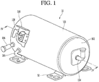
- Fig. 1 is a perspective view illustrating an outer appearance of a linear compressor according to an embodiment.
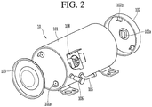
- Fig. 2 is an exploded perspective view illustrating a shell and a shell cover of the linear compressor according to an embodiment.
- a linear compressor 10 may include a shell 101 and shell covers 102 and 103 coupled to the shell 101.
- Each of the first and second shell covers 102 and 103 may be understood as one component of the shell 101.
- a leg 50 may be coupled to a lower portion of the shell 101.
- the leg 50 may be coupled to a base of a product in which the linear compressor 10 is installed or provided.
- the product may include a refrigerator, and the base may include a machine room base of the refrigerator.
- the product may include an outdoor unit of an air conditioner, and the base may include a base of the outdoor unit.
- the shell 101 may have an approximately cylindrical shape and be disposed to lie in a horizontal direction or an axial direction. In Fig. 1 , the shell 101 may extend in the horizontal direction and have a relatively low height in a radial direction. That is, as the linear compressor 10 has a low height, when the linear compressor 10 is installed or provided in the machine room base of the refrigerator, a machine room may be reduced in height.
- a terminal 108 may be installed or provided on an outer surface of the shell 101.
- the terminal 108 may be understood as a component for transmitting external power to a motor assembly (see reference numeral 140 of Fig. 3 ) of the linear compressor 10.
- the terminal 108 may be connected to a lead line of a coil (see reference numeral 141c of Fig. 3 ).
- a bracket 109 may be installed or provided outside of the terminal 108.
- the bracket 109 may include a plurality of brackets that surrounds the terminal 108.
- the bracket 109 may protect the terminal 108 against an external impact.
- Both sides of the shell 101 may be open.
- the shell covers 102 and 103 may be coupled to both open sides of the shell 101.
- the shell covers 102 and 103 may include a first shell cover 102 coupled to one open side of the shell 101 and a second shell cover 103 coupled to the other open side of the shell 101.
- An inner space of the shell 101 may be sealed by the shell covers 102 and 103.
- the first shell cover 102 may be disposed at a first or right portion of the linear compressor 10, and the second shell cover 103 may be disposed at a second or left portion of the linear compressor 10. That is, the first and second shell covers 102 and 103 may be disposed to face each other.
- the linear compressor 10 further includes a plurality of pipes 104, 105, and 106 provided in the shell 101 or the shell covers 102 and 103 to suction, discharge, or inject the refrigerant.
- the plurality of pipes 104, 105, and 106 may include a suction pipe 104 through which the refrigerant may be suctioned into the linear compressor 10, a discharge pipe 105 through which the compressed refrigerant may be discharged from the linear compressor 10, and a process pipe through which the refrigerant may be supplemented to the linear compressor 10.
- the suction pipe 104 may be coupled to the first shell cover 102.
- the refrigerant may be suctioned into the linear compressor 10 through the suction pipe 104 in an axial direction.
- the discharge pipe 105 may be coupled to an outer circumferential surface of the shell 101.
- the refrigerant suctioned through the suction pipe 104 may flow in the axial direction and then be compressed. Also, the compressed refrigerant may be discharged through the discharge pipe 105.
- the discharge pipe 105 may be disposed at a position which is adjacent to the second shell cover 103 rather than the first shell cover 102.
- the process pipe 106 may be coupled to the outer circumferential surface of the shell 101. A worker may inject the refrigerant into the linear compressor 10 through the process pipe 106.
- the process pipe 106 may be coupled to the shell 101 at a height different from a height of the discharge pipe 105 to avoid interference with the discharge pipe 105.
- the height may be understood as a distance from the leg 50 in the vertical direction (or the radial direction).
- At least a portion of the second shell cover 103 may be disposed adjacent to an inner circumferential surface of the shell 101, which corresponds to a point to which the process pipe 106 may be coupled. That is, at least a portion of the second shell cover 103 may act as a flow resistance to the refrigerant injected through the process pipe 106.
- the passage of the refrigerant introduced through the process pipe 106 may have a size that gradually decreases toward the inner space of the shell 101.
- a pressure of the refrigerant may be reduced to allow the refrigerant to be vaporized.
- oil contained in the refrigerant may be separated.
- the refrigerant from which the oil is separated may be introduced into a piston 130 to improve compression performance of the refrigerant.
- the oil may be understood as a working oil existing in a cooling system.
- a cover support part or support 102a may be disposed or provided on an inner surface of the first shell cover 102.
- a second support device or support 185 which will be described hereinafter, may be coupled to the cover support part 102a.
- the cover support part 102a and the second support device 185 may be understood as devices that support a main body of the linear compressor 10.
- the main body of the compressor may represent a part or portion provided in the shell 101.
- the main body may include a drive part or drive that reciprocates forward and backward and a support part or support that supports the drive part.
- the drive part may include parts or components, such as the piston 130, a magnet frame 138, a permanent magnet 146, a support 137, and a suction muffler 150.
- the support part may include parts or components, such as resonant springs 176a and 176b, a rear cover 170, a stator cover 149, a first support device or support 165, and a second support device or support 185.
- a stopper 102b may be disposed or provided on the inner surface of the first shell cover 102.
- the stopper 102b may be understood as a component that prevents the main body of the compressor, particularly, the motor assembly 140 from being bumped by the shell 101 and thus damaged due to vibration or an impact occurring during transportation of the linear compressor 10.
- the stopper 102b may be disposed or provided adjacent to the rear cover 170, which will be described hereinafter. Thus, when the linear compressor 10 is shaken, the rear cover 170 may interfere with the stopper 102b to prevent the impact from being transmitted to the motor assembly 140.
- a spring coupling part or portion 101a may be disposed or provided on the inner surface of the shell 101.
- the spring coupling part 101a may be disposed at a position which is adjacent to the second shell cover 103.
- the spring coupling part 101a may be coupled to a first support spring 166 of the first support device 165, which will be described hereinafter.
- the main body of the compressor may be stably supported inside of the shell 101.
- Fig. 3 is an exploded perspective view illustrating internal components of the linear compressor according to an embodiment.
- Fig. 4 is a cross-sectional view illustrating internal components of the linear compressor according to an embodiment.
- the linear compressor 10 may include a cylinder 120 provided in the shell 101, the piston 130, which linearly reciprocates within the cylinder 120, and the motor assembly 140, which functions as a linear motor to apply drive force to the piston 130.
- the motor assembly 140 When the motor assembly 140 is driven, the piston 130 may linearly reciprocate in the axial direction.
- the linear compressor 10 may further include a suction muffler 150 coupled to the piston 130 to reduce noise generated from the refrigerant suctioned through the suction pipe 104.
- the refrigerant suctioned through the suction pipe 104 may flow into the piston 130 via the suction muffler 150. For example, while the refrigerant passes through the suction muffler 150, the flow noise of the refrigerant may be reduced.
- the suction muffler 150 may include a plurality of mufflers 151, 152, and 153.
- the plurality of mufflers 151, 152, and 153 may include a first muffler 151, a second muffler 152, and a third muffler 153, which may be coupled to each other.
- the first muffler 151 may be disposed or provided within the piston 130, and the second muffler 152 may be coupled to a rear portion of the first muffler 151. Also, the third muffler 153 may accommodate the second muffler 152 therein and extend to a rear side of the first muffler 151. In view of a flow direction of the refrigerant, the refrigerant suctioned through the suction pipe 104 may successively pass through the third muffler 153, the second muffler 152, and the first muffler 151. In this process, the flow noise of the refrigerant may be reduced.
- the suction muffler 150 may further include a muffler filter 155.
- the muffler filter 155 may be disposed on or at an interface on or at which the first muffler 151 and the second muffler 152 are coupled to each other.
- the muffler filter 155 may have a circular shape, and an outer circumferential portion of the muffler filter 155 may be supported between the first and second mufflers 151 and 152.
- the "axial direction” may be understood as a direction in which the piston 130 reciprocates, that is, a horizontal direction in Fig. 4 .
- a direction from the suction pipe 104 toward a compression space P that is, a direction in which the refrigerant flows may be defined as a "frontward direction”
- a direction opposite to the frontward direction may be defined as a “rearward direction”.
- the compression space P may be compressed.
- the "radial direction” may be understood as a direction which is perpendicular to the direction in which the piston 130 reciprocates, that is, a vertical direction in Fig. 4 .
- the piston 130 may include a piston body 131 having an approximately cylindrical shape and a piston flange part or flange 132 that extends from the piston body 131 in the radial direction.
- the piston body 131 may reciprocate inside of the cylinder 120, and the piston flange part 132 may reciprocate outside of the cylinder 120.
- the cylinder 120 may be configured to accommodate at least a portion of the first muffler 151 and at least a portion of the piston body 131.
- the cylinder 120 may have the compression space P in which the refrigerant may be compressed by the piston 130.
- a suction hole 133 through which the refrigerant may be introduced into the compression space P, may be defined in a front portion of the piston body 131, and a suction valve 135 that selectively opens the suction hole 133 may be disposed or provided on a front side of the suction hole 133.
- a coupling hole, to which a predetermined coupling member 135a may be coupled, may be defined in an approximately central portion of the suction valve 135.
- a discharge cover 200 that defines a discharge space for the refrigerant discharged from the compression space P and a discharge valve assembly 161 and 163 coupled to the discharge cover 200 to selectively discharge the refrigerant compressed in the compression space P may be provided at a front side of the compression space P.
- the discharge cover 200 may include a plurality of covers (see reference numeral 210, 230, and 250 of Fig. 7 ).
- the discharge space may have a plurality of space parts or spaces defined by the plurality of covers 210, 230, and 250.
- the plurality of space parts may be disposed or provided in a front and rear direction to communicate with each other. This will be described hereinafter.
- the discharge valve assembly 161 and 163 may include a discharge valve 161 which may be opened when the pressure of the compression space P is above a discharge pressure to introduce the refrigerant into the discharge space and a spring assembly 163 disposed or provided between the discharge valve 161 and the discharge cover 200 to provide elastic force in the axial direction.
- the spring assembly 163 may include a valve spring 163a and a spring support part or support 163b that supports the valve spring 163a to the discharge cover 200.
- the valve spring 163a may include a plate spring.
- the discharge valve 161 may be coupled to the valve spring 163a, and a rear portion or rear surface of the discharge valve 161 may be disposed to be supported on a front surface of the cylinder 120.
- the compression space may be maintained in the sealed state.
- the compression space P may be opened to allow the refrigerant in the compression space P to be discharged.
- the compression space P may be understood as a space defined between the suction valve 135 and the discharge valve 161. Also, the suction valve 135 may be disposed on or at one side of the compression space P, and the discharge valve 161 may be disposed on or at the other side of the compression space P, that is, an opposite side of the suction valve 135.
- the suction valve 135 may be opened to suction the refrigerant into the compression space P.
- the suction valve 135 may compress the refrigerant of the compression space P in a state in which the suction valve 135 is closed.
- valve spring 163a When the pressure of the compression space P is above the discharge pressure, the valve spring 163a may be deformed forward to open the discharge valve 161. Here, the refrigerant may be discharged from the compression space P into the discharge space of the discharge cover 200. When the discharge of the refrigerant is completed, the valve spring 163a may provide restoring force to the discharge valve 161 to close the discharge valve 161.
- the linear compressor 10 may further include a cover pipe 162a coupled to the discharge cover 200 to discharge the refrigerant flowing through the discharge space of the discharge cover 200.
- the cover pipe 162a may be made of a metal material.
- the linear compressor 10 may further include a loop pipe 162b coupled to the cover pipe 162a to transfer the refrigerant flowing through the cover pipe 162a to the discharge pipe 105.
- the loop pipe 162b may have one or a first side or end coupled to the cover pipe 162a and the other or a second side or end coupled to the discharge pipe 105.
- a cover coupling part or portion 162c coupled to the cover pipe 162a is disposed on the one side portion of the loop pipe 162b, and a discharge coupling part or portion 162d coupled to the discharge pipe 105 may be disposed or provided on the other side portion of the loop pipe 162b.
- the loop pipe 162b may be made of a flexible material and have a relatively long length. Also, the loop pipe 162b may roundly extend from the cover pipe 162a along the inner circumferential surface of the shell 101 and be coupled to the discharge pipe 105. For example, the loop pipe 162b may have a wound shape.
- the linear compressor 10 may further include a frame 110.
- the frame 110 is understood as a component for fixing the cylinder 120.
- the cylinder 120 may be press-fitted into the frame 110.
- the frame 110 may be disposed or provided to surround the cylinder 120. That is, the cylinder 120 may be disposed or provided to be accommodated into the frame 110. Also, the discharge cover 200 may be coupled to a front surface of the frame 110 using a coupling member.
- the motor assembly 140 may include an outer stator 141 fixed to the frame 110 and disposed or provided to surround the cylinder 120, an inner stator 148 disposed or provided to be spaced inward from the outer stator 141, and the permanent magnet 146 disposed or provided in a space between the outer stator 141 and the inner stator 148.
- the permanent magnet 146 may be linearly reciprocated by mutual electromagnetic force between the outer stator 141 and the inner stator 148. Also, the permanent magnet 146 may be provided as a single magnet having one polarity or by coupling a plurality of magnets having three polarities to each other.
- the magnet frame 138 may be installed or provided on the permanent magnet 146.
- the magnet frame 138 may have an approximately cylindrical shape and be disposed or provided to be inserted into the space between the outer stator 141 and the inner stator 148.
- the magnet frame 138 may be coupled to the piston flange part 132 to extend in an outer radial direction and then be bent forward.
- the permanent magnet 146 may be installed or provided on a front portion of the magnet frame 138. When the permanent magnet 146 reciprocates, the piston 130 may reciprocate together with the permanent magnet 146 in the axial direction.
- the outer stator 141 may include coil winding bodies 141b, 141c, and 141d and a stator core 141a.
- the coil winding bodies 141b, 141c, and 141d may include a bobbin 141b and a coil 141c wound in a circumferential direction of the bobbin 141b.
- the coil winding bodies 141b, 141c, and 141d may further include a terminal part or portion 141d that guides a power line connected to the coil 141c so that the power line is led out or exposed to the outside of the outer stator 141.
- the stator core 141a may include a plurality of core blocks in which a plurality of laminations are laminated in a circumferential direction.
- the plurality of core blocks may be disposed or provided to surround at least a portion of the coil winding bodies 141b and 141c.
- a stator cover 149 may be disposed or provided on one or a first side of the outer stator 141. That is, the outer stator 141 may have one or a first side supported by the frame 110 and the other or a second side supported by the stator cover 149.
- the linear compressor 10 may further include a cover coupling member 149a for coupling the stator cover 149 to the frame 110.
- the cover coupling member 149a may pass through the stator cover 149 to extend forward to the frame 110 and then be coupled to a first coupling hole (not shown) of the frame 110.
- the inner stator 148 may be fixed to a circumference of the frame 110. Also, in the inner stator 148, the plurality of laminations may be laminated in the circumferential direction outside of the frame 110.
- the linear compressor 10 may further include a support 137 that supports the piston 130.
- the support 137 may be coupled to a rear portion of the piston 130, and the muffler 150 may be disposed or provided to pass through the inside of the support 137.
- the piston flange part 132, the magnet frame 138, and the support 137 may be coupled to each other using a coupling member.
- a balance weight 179 may be coupled to the support 137.
- a weight of the balance weight 179 may be determined based on a drive frequency range of the compressor body.
- the linear compressor 10 may further include a rear cover 170 coupled to the stator cover 149 to extend backward and supported by the second support device 185.
- the rear cover 170 may include three support legs, and the three support legs may be coupled to a rear surface of the stator cover 149.
- a spacer 181 may be disposed or provided between the three support legs and the rear surface of the stator cover 149.
- a distance from the stator cover 149 to a rear end of the rear cover 170 may be determined by adjusting a thickness of the spacer 181.
- the rear cover 170 may be spring-supported by the support 137.
- the linear compressor 10 may further include an inflow guide part or guide 156 coupled to the rear cover 170 to guide an inflow of the refrigerant into the muffler 150. At least a portion of the inflow guide part 156 may be inserted into the suction muffler 150.
- the linear compressor 10 may further include a plurality of resonant springs 176a and 176b which may be adjusted in natural frequency to allow the piston 130 to perform a resonant motion.
- the plurality of resonant springs 176a and 176b may include a first resonant spring 176a supported between the support 137 and the stator cover 149 and a second resonant spring 176b supported between the support 137 and the rear cover 170.
- the drive part that reciprocates within the linear compressor 10 may be stably moved by the action of the plurality of resonant springs 176a and 176b to reduce vibration or noise due to the movement of the drive part.
- the support 137 may include a first spring support part or support 137a coupled to the first resonant spring 176a.
- the linear compressor 10 may include a plurality of sealing members or seals 127, 128, 129a, and 129b that increases a coupling force between the frame 110 and the peripheral parts around the frame 110.
- the plurality of sealing members 127, 128, 129a, and 129b may include a first sealing member 127 disposed or provided at a portion at which the frame 110 and the discharge cover 200 are coupled to each other.
- the first sealing member 127 may be disposed or provided on or in a second installation groove (not shown) of the frame 110.
- the plurality of sealing members 127, 128, 129a, and 129b may further include a second sealing member 128 disposed or provided at a portion at which the frame 110 and the cylinder 120 are coupled to each other.
- the second sealing member 128 may be disposed on or in a first installation groove (not shown) of the frame 110.
- the plurality of sealing members 127, 128, 129a, and 129b may further include a third sealing member 129a disposed or provided between the cylinder 120 and the frame 110.
- the third sealing member 129a may be disposed or provided on or in a cylinder groove defined in the rear portion of the cylinder 120.
- the plurality of sealing members 127, 128, 129a, and 129b may further include a fourth sealing member 129b disposed or provided at a portion at which the frame 110 and the inner stator 148 are coupled to each other.
- the fourth sealing member 129b may be disposed or provided on or in a third installation groove (not shown) of the frame 110.
- Each of the first to fourth sealing members 127, 128, 129a, and 129b may have a ring shape.
- the linear compressor 10 may further include a first support device or support 165 coupled to a support coupling part or portion of the discharge cover 200 to support one side of the main body of the compressor 10.
- the first support device 165 may be disposed or provided adjacent to the second shell cover 103 to elastically support the main body of the compressor 10.
- the first support device 165 may include a first support spring 166.
- the first support spring 166 may be coupled to the spring coupling part 101a.
- the linear compressor 10 may further include the second support device 185 coupled to the rear cover 170 to support the other side of the main body of the compressor 10.
- the second support device 185 may be coupled to the first shell cover 102 to elastically support the main body of the compressor 10.
- the second support device 185 may include a second support spring 186.
- the second support spring 186 may be coupled to the cover support part 102a.
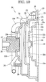
- Fig. 5 is a perspective view illustrating a coupled configuration of the discharge cover and the discharge valve assembly according to an embodiment.
- Fig. 6 is an exploded perspective view illustrating the coupled configuration of the discharge cover and the discharge valve assembly according to an embodiment.
- Fig. 7 is a cross-sectional view taken along line VI-VI' of FIG. 5 .
- the linear compressor 10 may include the discharge valve assembly 161 and 163 and the discharge cover 200 coupled to the discharge valve assembly 161 and 163 to define the discharge space of the refrigerant discharged from the compression space P of the cylinder 120.
- the discharge valve assembly 161 and 163 may be press-fitted and coupled to the discharge cover 200.
- the discharge valve assembly 161 and 163 may include the discharge valve 161 installed or provided on a front end of the cylinder 120 to selectively open the compression space P and the spring assembly 163 coupled to a front side of the discharge valve 161.
- the compression space P When the discharge valve 161 is closely attached to the front end of the cylinder 120, the compression space P may be closed.
- the discharge valve 161 moves forward and then is spaced apart from the cylinder 120, the refrigerant compressed in the compression space P may be discharged.
- the discharge valve 161 may be made of a plastic material.
- the discharge valve 161 may be made of a polyether ether ketone (PEEK) material.
- PEEK polyether ether ketone
- the PEEK material may have superior heat-resistance, impact strength, and wear resistance.
- the discharge valve 161 may have an avoid groove 161a that avoids the coupling member 135a of the suction valve 135.
- the avoid groove 161a may be recessed forward from a rear surface of the discharge valve 161.
- the spring assembly 163 may include the valve spring 163a coupled to the discharge valve 161.
- the valve spring 163a may include a plate spring having a plurality of cutoff grooves.
- a coupling hole, to which the discharge valve 161 may be coupled, may be defined in an approximately central portion of the valve spring 163a.
- the spring assembly 163 may include the spring support part 163b coupled to the valve spring 163a.
- the spring support part 163b may be understood as a component coupled to the discharge cover 200 to support the valve spring 163a to the discharge cover 200.
- the spring support part 163b may be press-fitted and coupled to the discharge cover 200.
- the spring support part 163b may be integrally injection-molded to the valve spring 163a through an injection-molding process, for example.
- the discharge cover 200 may further include a gasket 164 installed or provided on or at a front side of the spring assembly 163.
- the gasket 164 may allow the spring assembly 163 to be closely attached to the discharge cover 200 to prevent the refrigerant from leaking through a space between the spring assembly 163 and the discharge cover 200.
- the spring support part 163b may include a first protrusion 163c that prevents the discharge valve 161 and the spring assembly 163 from rotating.
- a plurality of the first protrusion 163c may be provided on an outer circumferential surface of the spring support part 163b.
- the gasket 164 may further include a second protrusion 164a corresponding to a position and shape of the first protrusion 163c. That is, a plurality of second protrusions 164a may be disposed or provided on an outer circumferential surface of the gasket 164.
- the discharge cover 200 may further include a recess part or recess 217 coupled to the outer circumferential surface of the spring assembly 163 or the outer circumferential surface of the gasket 164.
- the first protrusion 163c and the second protrusion 164a may be coupled to the recess part 217.
- the recess part 217 may be defined in the first cover 210 and a plurality of the recess part 217 may be provided to correspond to the plurality of first and second protrusions 163c and 164a.
- the gasket 164 may be seated on a third part or portion 213 of the discharge cover 200.
- the second protrusion 164a of the gasket 164 may be inserted into the recess part 217.
- the spring assembly 163 may be press-fitted into the discharge cover 200. When the gasket 164 is pressed, a front surface of the spring assembly 163 may be coupled to the third part 213, and the first protrusion 163c may be disposed or provided in the recess part 217. In this process, the spring support part 163b may be deformed.
- the spring assembly 163 As the spring assembly 163 is press-fitted into the discharge cover 200, the spring assembly 163 and the discharge valve 161 may be stably supported by the discharge cover 200. Also, as the first and second protrusions 163c and 164a may be coupled to the recess part 217, rotation of the spring assembly 163 and the discharge valve 161 may be prevented.
- the discharge cover 200 may include a first cover 210 that defines a first space part or space in which the discharge valve 161 and the spring assembly 163 may be disposed or provided.
- the first cover 210 may be stepped forward.
- the first cover 210 may include a first part or portion 211 that defines a rear surface of the first cover 210 and provides a coupling surface to which the frame 110 may be coupled and a first stepped part or step 215a that extends forward from the first part 211.
- the first cover 210 may have a shape which may be recessed forward from the first part 211 by the first stepped part 215a.
- the first cover 210 may further include a second part or portion 212 that extends by a first preset or predetermined length inward from the first stepped part 215a in a radial direction.
- the first cover 210 may further include a second stepped part or step 215b that extends forward from the second part 212.
- the first cover 210 may have a shape which may be recessed forward from the second part 212 by the second stepped part 215b.
- the recess part 217 may be defined in an outer circumferential surface of the second stepped part 215b.
- the first cover 210 may further include a third part or portion 213 extending by a second preset or predetermined length inward from the second stepped part 215b in the radial direction.
- the third part 213 may have a seating surface on which the spring assembly 163 may be seated.
- the gasket 164 may be disposed or provided on the third part 213, and the spring assembly 163 may be coupled to a rear side of the third part 213.
- the third part 213 may be coupled to a front surface of the spring assembly 163.
- the outer circumferential surface of the spring assembly 163 may be press-fitted into the second stepped part 215b.
- the first cover 210 may further include a third stepped part or step 215c that extends forward from the third part 213.
- the first cover 210 may have a shape which may be recessed forward from the third part 213 by the third stepped part 215c.
- the first cover 210 may further include a fourth part or portion 214 that extends inward from the third stepped part 215 in the radial direction.
- a stopper 218 that protrudes backward may be disposed or provided on an approximately central portion of the fourth part 214.
- the abnormal operation may be understood as a momentary abnormal behavior of the discharge valve 161 due to a variation in flow rate or pressure within the compressor.
- the stopper 218 may interfere with the discharge valve 161 or the valve spring 163a to prevent the discharge valve 161 or the valve spring 163a from further moving forward.
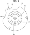
- Discharge holes 216a and 216b through which the refrigerant flowing through the first space part 210a may be transferred to the second cover 230, may be defined in the first cover 210.
- the discharge holes 216a and 216b may include a first discharge hole 216a defined in the second part 212.
- a plurality of the first discharge hole 216a may be provided, and the plurality of first discharge holes 216a may be disposed or provided to be spaced apart from each other along a circumference of the second part 212.
- the refrigerant, which does not pass through the spring assembly 163, of the refrigerant flowing into the first space part 210a, that is, the refrigerant existing in or at an upstream side of the spring assembly 163 may be discharged to the outside of the first cover 210 through the first discharge hole 216a. Also, the refrigerant discharged through the first discharge hole 216a may be introduced into the second space part 230a of the second cover 230.
- the discharge holes 216a and 216b may include a second discharge hole 216b defined in the fourth part 214.
- a plurality of the second discharge hole 216b may be provided, and the plurality of second discharge holes 216b may be disposed or provided to be spaced apart from each other along a circumference of the fourth part 214.
- the refrigerant which passes through the spring assembly 163, of the refrigerant flowing into the first space part 210a, that is, the refrigerant existing in or at a downstream side of the spring assembly 163 may be discharged to the outside of the first cover 210 through the second discharge hole 216b. Also, the refrigerant discharged through the second discharge hole 216b may be introduced into the second space part 230a of the second cover 230.
- the number of second discharge holes 216b may be less than the number of first discharge holes 216a.
- a relatively large amount of refrigerant may pass through the first discharge holes 216a, and a relatively small amount of refrigerant may pass through the second discharge holes 216b.
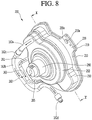
- Fig. 8 is a perspective view of the discharge cover according to an embodiment.
- Fig. 9 is a view illustrating an internal configuration of the first cover of the discharge cover according to an embodiment.
- Fig. 10 is a cross-sectional view taken along line X-X' of FIG. 8 .
- Fig. 11 is a cross-sectional view of a state in which the connection pipe is coupled to the second cover according to an embodiment.
- the discharge cover 200 may include the plurality of covers 210, 230, and 250 defining a plurality of discharge spaces or a plurality of discharge chambers.
- the plurality of covers 210, 230, and 250 may be coupled to the frame 110 and stacked forward with respect to the frame 110.
- the plurality of covers 210, 230, and 250 may include the first cover 210 having the first part 211 coupled to the front surface of the frame 110 and the second cover 230 coupled to a front side of the first cover 210.
- the first and second covers 210 and 230 may be stacked in the axial direction.
- the discharge cover 200 may include a third cover 250 coupled to a front side of the second cover 230.
- the second and third covers 230 and 250 may be stacked in the axial direction.
- the first to third covers 210, 230, and 250 may be stacked in the axial direction.
- the plurality of covers 210, 230, and 250 may include cover holes 219a and 239a, to which a predetermined coupling member may be coupled.
- the cover holes 219a and 239a may include a first cover hole 219a defined in the first cover 210 and a second cover hole 239a defined in the second cover 230.
- the first cover hole 219a may be defined in a first cover flange 219 disposed or provided an edge of the first cover 210, and the second cover hole 239a may be defined in a second cover flange 239 disposed or provided on or at an edge of the second cover 230.
- a plurality of each of the first cover holes 219a and 239a may be provided.
- a rear surface of the first cover flange 219 may define the first part 211.
- the coupling member may pass through the first and second cover holes 219a and 239a and then be coupled to a coupling hole (not shown) of the frame 110.
- a coupling hole (not shown) of the frame 110.
- the first cover flange 219 and the second cover flange 239 may be coupled to each other, and the first and second covers 210 and 230 may be stably supported by the frame 110.
- the first cover 210 may have a stepped structure. Also, the first space part 210a, through which the refrigerant discharged through the discharge valve 161 may flow, may be defined within the first cover 210.
- the second cover 230 may be coupled to an outer surface of the first cover 210. As described above, as the first and second cover flanges 219 and 239 are coupled to each other, the first and second covers 210 and 230 may be coupled to each other. Also, the second space part 230a, through which the refrigerant may flow, may be defined between the outer surface of the first cover 210 and an inner surface of the second cover 230. The refrigerant discharged from the first cover 210 through the first and second discharge holes 216a and 216b of the first cover 210 may be introduced into the second space part 230a.
- the second cover 230 may have a structure which may be stepped forward.
- the second cover 230 may include the fourth part 231 coupled to the outer surface of the first cover 210.
- the fourth part 231 may be disposed or provided on a rear surface of the second cover flange 239.
- the second cover 230 may further include a fourth stepped part or step 235a that extends forward from the fourth part 231.
- the second cover 230 may have a shape which may be recessed forward from the fourth part 231 by the fourth stepped part 235a.
- the second cover 230 may include a fifth part or portion 232 that extends by a third preset or predetermined length inward from the fourth stepped part 235a in the radial direction.
- the second cover 230 may include a fifth stepped part or step 235b that extends forward from the fifth part 232 and a sixth part or portion 233 that extends inward from the fifth stepped part 235b in the radial direction.
- the second cover 230 may have a shape which may be recessed forward from the fifth part 232 by the fifth stepped part 235b.
- the third cover 250 may be coupled to the outer surface of the second cover 230.
- the third cover 250 may be coupled to the fifth part 232 or the fifth stepped part 235b of the second cover 230.
- the fifth part 232 and the fifth stepped part 235b may be coupled to an inner surface of the third cover 250.
- a third space part or space 250a, through which the refrigerant may flow, may be defined between the outer surface of the second cover 230 and an inner surface of the third cover 250.
- the third space part 250a may be understood as a space between the sixth part 233 of the second cover 230 and the inner surface of the third cover 250.
- a volume ratio of the first to third space parts 210a, 230a, and 250a may be determined or set to a preset or predetermined ratio.
- the second space part 230a may have a volume greater than a volume of the first space part 210a
- the third space part 250a may have a volume less than the volume of the second space part 230a.
- the refrigerant may flow from the first space part 210a to the second space part 230a having the relatively large volume to reduce pulsation and noise.
- the refrigerant may flow from the second space part 230a to the third space part 250a having the relatively small volume to secure a flow rate of the refrigerant.
- first and third space parts 210a and 250a may have the same volume, and the second space part 230a may have a volume greater than the volume of each of the first and third space parts 210a and 250a. More particularly, the first, second, and third space parts 210a, 230a, and 250a may have a volume ration of about 1:2.5:1.
- the third cover 250 may include a third cover flange 259 coupled to the fifth part 232 of the second cover 230.
- a seventh part or portion 251 coupled to the fifth part 232 may be defined in a rear surface of the third cover flange 259.
- the third cover 250 may have a stepped structure.
- the third cover 250 may include a stepped part or step that extends forward from the seventh part 251 and a part or portion that extends inward from the stepped part in the radial direction.
- a plurality of each of the stepped part and the part may be provided, and the plurality of stepped parts and the plurality of parts may alternately extend. As the shape is clearly shown in the drawings, separate reference numeral have not been given for description.
- a coupling hole 257, to which the support coupling part 290 may be coupled, may be defined in an approximately central portion of the third cover 250.
- the support coupling part 290 may be a component that supports the discharge cover 200 to the first support device 165, made of a metal material, and coupled to the first support device 165 by a predetermined coupling member.
- the support coupling part 290 may have one or a first side portion coupled to the coupling hole 257 and the other or a second side portion coupled to the first support device 165. As the support coupling part 290 may be inserted into the third cover 250 through the coupling hole 257, the support coupling part 290 may be stably coupled to the discharge cover 200. Due to the above-described structure, vibration generated from the discharge cover 200 may be transmitted to the first support device 165 through the support coupling part 290. Also, vibration transmitted to the first support device 165 may be dispersed to the shell 101 via the first support spring 166 and the spring coupling part 101a. As a result, vibration of the linear compressor 10 may be reduced.
- the discharge cover 200 may further include the connection pipe 260 through which the refrigerant within the second space part 230a may be transferred to the third space part 250a of the third cover 250.
- the connection pipe 260 may be coupled to the second cover 230 to extend to the outside of the second cover 230 and then be bent at least one time and coupled to the third cover 250.
- the connection pipe 260 may include a first pipe 261 coupled to the second cover 230 to extend in a first direction, a second pipe 263 bent from the first pipe 261 to extend in a second direction, and a third pipe 265 bent from the second pipe 263 to extend in a third direction and then coupled to the third cover 250.
- the first direction may be understood as a direction which extends away from the second cover 230
- the second direction may be understood as a direction which extends approximately perpendicular to the first direction
- the third direction may be understood as a direction which extends approximately perpendicular to the second direction.
- the third direction may be understood as a direction which is directed to the third cover 250.
- connection pipe 260 may have a shape which is bent several times in a " c" shape by the first to third pipes 261, 263, and 265. As the connection pipe 260 is provided in the discharge cover 200, the discharge passage for the refrigerant may be elongated, and thus, pulsation of the refrigerant may be reduced.
- the first pipe 261 may be coupled to the second cover 230 to extend toward the second space part 230a of the second cover 230. Also, an end of the first pipe 261 may be spaced a preset or predetermined distance H from the outer surface of the first cover 210, more particularly, the first cover flange 219.
- the preset distance H may be determined as a value which corresponds to a height of the first stepped part 215a from the first cover flange 219 of the first cover 210. That is, the end of the first pipe 261 may be disposed at a height corresponding to the second part 212 in which the first discharge hole 216a is defined.
- the "height" may be understood as a forward distance using the first cover flange 219 as a reference point.
- the preset distance H1 may range from about 1 mm to 2 mm. When the preset distance H1 is less than about 1 mm or greater than about 2 mm, pressure loss of the refrigerant may occur (see Fig. 12 ).
- the third pipe 265 may be coupled to the third cover 250.
- the refrigerant introduced from the first space part 210a of the first cover 210 to the second space part 230a of the second cover 230 through the first discharge hole 216a may be discharged to the outside of the second cover 230 while flowing through the first pipe 261.
- the refrigerant within the first pipe 261 may flow to the outer surface of the third cover 250 while flowing through the second pipe 263 and then be introduced into the third space part 250a of the third cover 250 through the third pipe 265. Also, the refrigerant within the third space part 250a flows to the cover pipe 162a coupled to the third cover 250.
- the cover pipe 261a may extend a preset or predetermined length from the third cover 250 to the third space part 250a.
- connection pipe 260 that extends to the outside of the second cover 230 and is coupled to the outer surface of the third cover 250 is provided, the discharge passage for the refrigerant may be elongated, and thus, pulsation of the refrigerant may be reduced.
- the refrigerant flowing through the cover pipe 162a may flow through the loop pipe 162b and then be discharged to the outside of the linear compressor 10 through the discharge pipe 105 connected to the loop pipe 162b.
- Fig. 12 is a test graph illustrating pressure drop depending on a variation in distance H1 between the connection pipe and the outer surface of the first cover according to an embodiment.
- Fig. 13 is an experimental graph illustrating a state in which pulsation is reduced in comparison to the related art in a case of the stack-type discharge cover structure according to an embodiment.
- Fig. 14 is an experimental graph illustrating a state in which the pulsation varies depending on a length of the connection pipe according to an embodiment.
- the pressure drop of the refrigerant varies depending on a variation in the preset distance (H1, a gap).
- H1 preset distance
- ⁇ P pressure drop
- the pressure drop of the refrigerant is relatively high.
- the preset pressure drop is a preset drop ( ⁇ Po)
- the preset distance H1 is less than about 1 mm, the pressure drop is measured to a value greater than the preset drop.
- the more the preset distance H1 approaches about 1 mm the more the pressure drop is reduced.
- the preset distance H1 when the preset distance H1 is above about 1 mm, the pressure drop is less than the preset drop ( ⁇ Po). A section in which the pressure drop is less than the preset drop ( ⁇ Po), it is observed that the preset distance H1 ranges from about 1 mm to about 2 mm. Also, the preset distance H1 at which the lowest pressure drop occurs may be about 1.5 mm. Thus, in the current embodiment, the preset distance H1 may range from about 1 mm to about 2 mm, for example, about 1.5 mm.
- the pulsation varies depending on a variation in frequency (Hz) of the refrigerant discharged from the discharge cover 200.
- the frequency (Hz) may be understood as a loudness frequency which is obtained from the discharged refrigerant, but not an input frequency (about 80 Hz to about 110 Hz) of the linear compressor 10.
- the pulsation may be understood as a relative value which is expressed according to a predetermined reference.
- a solid line shows results due to the structure of the discharge cover 200 according to an embodiment
- a dotted line shows results due to the structure of the discharge cover according to the related art, that is, the Prior Art Document 2.
- the pulsation measured depending on a length of the connection pipe 260 varies.
- the frequency (Hz) displayed on the horizontal axis of the graph may be understood as a loudness frequency.
- the pulsation may be understood as a relative value that is expressed according to the predetermined reference.
- a solid line shows a variation in pulsation depending on a variation in frequency when a length of the connection pipe 260 according to an embodiment, that is, a sum of lengths of the first to third pipes 261, 263, and 265 ranges from about 70 mm to about 80 mm, for example, about 75 mm
- a dotted line shows a variation in pulsation depending on a variation in frequency when the connection pipe 260, which is a control group with respect to the experimental group, has a length of about 70 mm or less.
- connection pipe 260 may have a length of about 70 mm to about 80 mm, for example, about 75 mm.
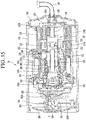
- Fig. 15 is a cross-sectional view illustrating a state in which the refrigerant flows in the linear compressor according to an embodiment. Referring to Fig. 15 , a refrigerant flow in the linear compressor 10 according to an embodiment will be described hereinafter.
- the refrigerant suctioned into the shell 101 through the suction pipe 104 may be introduced into the piston 130 via the suction muffler 150.
- the piston 130 reciprocates in the axial direction by the driving of the motor assembly 140.
- the suction valve 135 coupled to the front side of the piston 130 When the suction valve 135 coupled to the front side of the piston 130 is opened, the refrigerant may be introduced into the compression space P and then compressed. Also, when the discharge valve 161 is opened, the compressed refrigerant may be introduced into the discharge space of the discharge cover 200.
- the refrigerant may flow to the first space part 210a of the first cover 210 and then flow to the second space part 230a of the second cover 230 through the first and second discharge holes 216a and 216b (see Fig. 7 ). Also, the refrigerant within the second space part 230a may be discharged to the outside of the second cover 230 through the first pipe 261 of the connection pipe 260 (see Figs. 8 and 11 ) and then introduced into the third space part 250a of the third cover 250 via the second pipe 263 and the third pipe 265 (see Fig. 7 ).
- the refrigerant within the third space part 250a may be discharged from the discharged cover 200 through the cover pipe 162a and then discharge to the outside of the linear compressor 10 via the loop pipe 162b and the discharge pipe 105 (see Figs. 7 and 8 ).
- pulsation of the compressed refrigerant discharged through the discharge valve may be reduced by the discharge cover including the plurality of covers which may be stacked in the axial direction, and thus, noise may be reduced.
- the compressor including internal parts or components may be decreased in size to reduce a volume of a machine room of a refrigerator, and thus, an inner storage space of the refrigerant may be increased. Also, a drive frequency of the compressor may be increased to prevent the internal parts from being deteriorated in performance due to the decreasing size thereof.
- the gas bearing may be applied between the cylinder and the piston to reduce a friction force occurring due to oil.
- the discharge space may be increased in volume, and thus, the pulsation of the discharged refrigerant may be reduced. Also, as the plurality of covers are may be stacked in the axial direction, a volume of the entire discharge cover may be relatively small while the discharge space is increased in volume to improve space availability. Also, noise generated by the flowing refrigerant may be effectively blocked through the structure of the stacked covers.
- the ratio of sizes of the first to third space parts which are defined by the first to third covers, may be determined to be in an optimal range, a reduction effect of pulsation and noise may be superior.
- the first space part is defined in the first cover
- the second space part is defined between the outer surface of the first cover and the inner surface of the second cover
- the third space part is defined between the outer surface of the second cover and the inner surface of the third cover
- connection pipe connecting the second space part to the third space part has a relatively long length
- the discharge passage may be increased in length, and thus, pulsation of the refrigerant may be reduced.
- connection pipe is inserted into the second cover, and the end of the connection pipe is spaced a preset or predetermined distance from the outer surface of the first cover, a pressure loss of the flowing refrigerant may be reduced.
- Embodiments provide a linear compressor in which a discharge space of a discharge cover is improved in structure to reduce an occurrence of pulsation due to a flow of a refrigerant. Embodiments also provide a linear compressor in which a plurality of discharge spaces (or discharge chambers) are provided in a discharge cover.
- Embodiments also provide a linear compressor in which a passage of a refrigerant flowing through a plurality of discharge spaces increased in length to reduce an occurrence of pulsation. Embodiments also provide a linear compressor in which an optical range with respect to a volume ratio of the plurality of discharge spaces is proposed to reduce an occurrence of pulsation.
- Embodiments also provide a linear compressor in which an optimal range with respect to a shape or length of a connection pipe through which one discharge space of a plurality of discharge spaces communicates with the other discharge space is proposed to reduce an occurrence of pulsation.
- a linear compressor may include a discharge cover including a plurality of covers which may be stacked in an axial direction.
- the discharge cover may include a first cover having a first space part or space through which a refrigerant may flow.
- a spring assembly may be installed on the first cover.
- the discharge cover may further include a second cover coupled to the first cover and having a second space part through which the refrigerant flows.
- the first cover may include a discharge hole through which the refrigerant within the first space part is transferred to the second space part.
- the first cover may have a structure which may be stepped several times.
- the first cover may have a recess part or recess to which an outer circumferential surface of the spring assembly is coupled.
- the discharge cover may further include a third cover coupled to the second cover and having a third space part or space through which the refrigerant may flow.
- the discharge cover may further include a connection pipe that extends from the second cover and is coupled to the third cover to transfer the refrigerant within the second space part to the third space part.
- connection pipe may have a shape which may be bent several times.
- the connection pipe may be coupled to the second cover to extend toward the first space part, and an end of a first pipe may be spaced a preset or predetermined distance (H1) from an outer surface of the first cover.
- a linear compressor may include a discharge cover.
- the discharge cover may include a first cover having a first space part or space, a second cover coupled to a front portion of the first cover and having a second space part or space, and a third cover coupled to a front portion of the second cover and having a third space part or space.
- the second space part may have a volume greater than that of each of the first space part and the third space part.
- any reference in this specification to "one embodiment,” “an embodiment,” “example embodiment,” etc. means that a particular feature, structure, or characteristic described in connection with the embodiment is included in at least one embodiment.
- the appearances of such phrases in various places in the specification are not necessarily all referring to the same embodiment.
Description
- A linear compressor is disclosed herein.
- Cooling systems are systems in which a refrigerant circulates to generate cool air. In such a cooling system, processes of compressing, condensing, expanding, and evaporating the refrigerant are repeatedly performed. For this, the cooling system includes a compressor, a condenser, an expansion device, and an evaporator. Also, the cooling system may be installed in a refrigerator or air conditioner which is a home appliance.
- In general, compressors are machines that receive power from a power generation device, such as an electric motor or a turbine, to compress air, a refrigerant, or various working gases, thereby increasing pressure. Compressors are being widely used in home appliances or industrial fields.
- Compressors may be largely classified into reciprocating compressors, in which a compression space into/from which a working gas is suctioned and discharged, is defined between a piston and a cylinder to allow the piston to be linearly reciprocated into the cylinder, thereby compressing a refrigerant, rotary compressors, in which a compression space into/from which a working gas is suctioned or discharged, is defined between a roller that eccentrically rotates and a cylinder to allow the roller to eccentrically rotate along an inner wall of the cylinder, thereby compressing a refrigerant, and scroll compressors, in which a compression space into/from which a refrigerant is suctioned or discharged, is defined between an orbiting scroll and a fixed scroll to compress a refrigerant while the orbiting scroll rotates along the fixed scroll. In recent years, a linear compressor, which is directly connected to a drive motor, in which a piston linearly reciprocates, to improve compression efficiency without mechanical losses due to movement conversion, and having a simple structure, is being widely developed. In general, the linear compressor may suction and compress a refrigerant while a piston linearly reciprocates in a sealed shell by a linear motor and then discharge the refrigerant.
- The linear motor is configured to allow a permanent magnet to be disposed between an inner stator and an outer stator. The permanent magnet may linearly reciprocate by an electromagnetic force between the permanent magnet and the inner (or outer) stator. Also, as the permanent magnet operates in the state in which the permanent magnet is connected to the piston, the permanent magnet may suction and compress the refrigerant while linearly reciprocating within the cylinder and then discharge the refrigerant.
- The present applicant has filed a patent (hereinafter, referred to as "Prior
Art Document 1") and then has registered the patent with respect to the linear compressor,Korean Patent Registration No. 10-1307688, registered on September 5, 2013 Art Document 1 includes a shell for accommodating a plurality of parts. A vertical height of the shell may be somewhat high as illustrated inFig. 2 of thePrior Art Document 1. Also, an oil supply assembly for supplying oil between a cylinder and a piston may be disposed within the shell. - When the linear compressor is provided in a refrigerator, the linear compressor may be disposed in a machine room provided at a rear side of the refrigerator. In recent years, a major concern of a customer is increasing an inner storage space of the refrigerator. To increase the inner storage space of the refrigerator, it may be necessary to reduce a volume of the machine room. Also, to reduce the volume of the machine room, it may be important to reduce a size of the linear compressor.
- However, as the linear compressor disclosed in the Prior
Art Document 1 has a relatively large volume, it is necessary to increase a volume of a machine room into which the linear compressor is accommodated. Thus, the linear compressor having a structure disclosed in the PriorArt Document 1 is not adequate for the refrigerator for increasing the inner storage space thereof. - To reduce the size of the linear compressor, it may be necessary to reduce a size of a main part or component of the compressor. In this case, performance of the compressor may deteriorate. To compensate for the deteriorated performance of the compressor, the compressor drive frequency may be increased. However, the more the drive frequency of the compressor is increased, the more a friction force due to oil circulating into the compressor increases, deteriorating performance of the compressor.
- To solve these limitations, the present applicant has filed a patent application (hereinafter, referred to as "Prior
Art Document 2"),Korean Patent Publication No. 10-2016-0000324 published on January 4, 2016 Document 2, a gas bearing technology in which a refrigerant gas is supplied in a space between a cylinder and a piston to perform a bearing function is disclosed. The refrigerant gas flows to an outer circumferential surface of the piston through a nozzle of the cylinder to act as a bearing in the reciprocating piston. - The linear compressor disclosed in the Prior
Art Document 2 includes a discharge cover to which a discharge valve is coupled. A discharge space through which a compression refrigerant discharged through the discharge valve flows is defined in the discharge cover. However, in the structure of the discharge cover according to the related art, there are limitations in which the discharge space has a relatively small volume, a discharge passage through which the compression refrigerant flows has a short length, and pulsation due to a flow of the refrigerant increases. The discharge cover or peripheral parts or components coupled to the discharge cover may be vibrated by the pulsation of the generated refrigerant gas, and the vibration may be transmitted to a shell through a support device supporting the discharge cover, causing vibration in the entire compressor and thereby generating resulting noise. -
WO 02/095231 A1 -
US 2006/093498 A1 discloses a linear compressor in which a bonding position of a muffler can be accurately determined when the muffler is bonded to a fixing plate so that a center axis of a discharge spring casing formed at the muffler accurately coincides with a center axis of an insertion hole formed at the fixing plate. -
WO 2014/053039 A1 describes a gas discharge system for a refrigeration compressor and a refrigeration compressor. - The present invention is defined by
independent claim 1; the dependent claims describe embodiments of the invention. - A linear compressor according to an embodiment comprises: a cylinder having a compression space for a refrigerant and into which a piston that reciprocates in an axial direction is inserted; a discharge valve provided at one side of the cylinder to selectively discharge the refrigerant compressed in the compression space for the refrigerant; a spring assembly coupled to the discharge valve; and a discharge cover on which the spring assembly is seated, the discharge cover having a discharge space through which the refrigerant discharged through the discharge valve flows, wherein the discharge cover includes a plurality of covers stacked in the axial direction.
- The linear compressor further includes a first cover on which the spring assembly is seated and having a first space through which the refrigerant flows; and a second cover coupled to the first cover and having a second space through which the refrigerant flows.
- The discharge cover further includes a third cover coupled to the second cover and having a third space through which the refrigerant flows.
- The discharge cover further includes a connection pipe that extends from the second cover and is coupled to a third cover of the plurality of the covers, the connection pipe being configured to transfer the refrigerant in the space of second cover to the space of the third cover.
- Each of the plurality of covers having a space in communication with a space of another of the plurality of covers and through which the refrigerant flows, at least two of the spaces of the plurality of covers having a different volume.
- A first cover of the plurality of covers includes a discharge hole through which the refrigerant in the space of the first cover is transferred to the second space of the second cover.
- The first cover may include a first portion coupled to a frame; a first step that may extend to be stepped forward from the first portion; and a second portion that may extend from the first step in a radial direction, wherein the cylinder may be inserted into the frame. The second portion may include a first discharge hole through which the refrigerant in the first space is transferred to the second space.
- The first cover may include a second step that extends to be stepped forward from the second portion; and a recess defined in the second step and coupled to an outer circumferential surface of the spring assembly.
- The first cover may further include a third portion that extends from the second step in the radial direction, and wherein a front surface of the spring assembly is provided in the third portion.
- The first cover may further include a third step that extends to be stepped forward from the third portion; and a fourth portion that extends from the third step in the radial direction.
- The fourth portion may include a second discharge hole through which the refrigerant in the first space is transferred to the second space.
- The connection pipe has a shape which may be bent several times.
- The connection pipe may include: a first pipe coupled to the second cover to extend in a first direction; a second pipe bent from the first pipe to extend in a second direction; and a third pipe bent from the second pipe to extend in a third direction and coupled to the third cover.
- The connection pipe may be coupled to the second cover to extend toward the first space, and an end portion of the first pipe is spaced a predetermined distance from an outer surface of the first cover.
- The predetermined distance may range from about 1 mm to about 2 mm, and wherein a sum of lengths of the first to third pipes ranges from about 70 mm to about 80 mm.
- A linear compressor according to another embodiment comprises: a cylinder having a compression space; a discharge valve provided at one side of the cylinder to discharge the refrigerant compressed in the compression space for the refrigerant; and a discharge cover provided at a front side of the discharge valve, wherein the discharge cover includes: a first cover having a first space; a second cover coupled to a front portion of the first cover and having a second space; and a third cover coupled to a front portion of the second cover and having a third space.
- The second space may have a volume greater than a volume of each of the first space and the third space.
- The first space and the third space may have the same volume.
- A volume ratio of the first space, the second space, and the third space may be about 1:2.5:1.
- Embodiments will be described in detail with reference to the following drawings in which like reference numerals refer to like elements, and wherein:
-
Fig. 1 is a perspective view illustrating an outer appearance of a linear compressor according to an embodiment; -
Fig. 2 is an exploded perspective view illustrating a shell and a shell cover of the linear compressor according to an embodiment; -
Fig. 3 is an exploded perspective view illustrating internal components of the linear compressor according to an embodiment; -
Fig. 4 is a cross-sectional view, taken along line IV-IV' ofFig. 1 ; -
Fig. 5 is a perspective view illustrating a coupled configuration of a discharge cover and a discharge valve assembly according to an embodiment; -
Fig. 6 is an exploded perspective view illustrating the coupled configuration of the discharge cover and the discharge valve assembly according to an embodiment; -
Fig. 7 is a cross-sectional view, taken along line VII-VII' ofFIG. 5 ; -
Fig. 8 is a perspective view of the discharge cover according to an embodiment; -
Fig. 9 is a view illustrating an internal configuration of a first cover of the discharge cover according to an embodiment; -
Fig. 10 is a cross-sectional view, taken along line X-X' ofFIG. 8 ; -
Fig. 11 is a cross-sectional view illustrating a state in which a connection pipe is coupled to a second cover according to an embodiment; -
Fig. 12 is a test graph illustrating pressure drop depending on a variation in distance H1 between the connection pipe and an outer surface of the first cover according to an embodiment; -
Fig. 13 is an experimental graph illustrating a state in which pulsation is reduced in comparison to the related art in a case of a stack-type discharge cover structure according to an embodiment; -
Fig. 14 is an experimental graph illustrating a state in which the pulsation varies depending on a length of the connection pipe according to an embodiment; and -
Fig. 15 is a cross-sectional view illustrating a state in which a refrigerant flows in the linear compressor according to an embodiment. - Hereinafter, exemplary embodiments will be described with reference to the accompanying drawings. The embodiments may, however, be embodied in many different forms and should not be construed as being limited to the embodiments set forth herein; rather, that alternate embodiments included in other retrogressive inventions or falling within the scope of the present disclosure will fully convey the concept to those skilled in the art.
-
Fig. 1 is a perspective view illustrating an outer appearance of a linear compressor according to an embodiment.Fig. 2 is an exploded perspective view illustrating a shell and a shell cover of the linear compressor according to an embodiment. - Referring to
Figs. 1 and2 , alinear compressor 10 according to an embodiment may include ashell 101 and shell covers 102 and 103 coupled to theshell 101. Each of the first and second shell covers 102 and 103 may be understood as one component of theshell 101. - A
leg 50 may be coupled to a lower portion of theshell 101. Theleg 50 may be coupled to a base of a product in which thelinear compressor 10 is installed or provided. For example, the product may include a refrigerator, and the base may include a machine room base of the refrigerator. For another example, the product may include an outdoor unit of an air conditioner, and the base may include a base of the outdoor unit. - The
shell 101 may have an approximately cylindrical shape and be disposed to lie in a horizontal direction or an axial direction. InFig. 1 , theshell 101 may extend in the horizontal direction and have a relatively low height in a radial direction. That is, as thelinear compressor 10 has a low height, when thelinear compressor 10 is installed or provided in the machine room base of the refrigerator, a machine room may be reduced in height. - A terminal 108 may be installed or provided on an outer surface of the
shell 101. The terminal 108 may be understood as a component for transmitting external power to a motor assembly (seereference numeral 140 ofFig. 3 ) of thelinear compressor 10. The terminal 108 may be connected to a lead line of a coil (see reference numeral 141c ofFig. 3 ). - A
bracket 109 may be installed or provided outside of the terminal 108. Thebracket 109 may include a plurality of brackets that surrounds the terminal 108. Thebracket 109 may protect the terminal 108 against an external impact. - Both sides of the
shell 101 may be open. The shell covers 102 and 103 may be coupled to both open sides of theshell 101. The shell covers 102 and 103 may include afirst shell cover 102 coupled to one open side of theshell 101 and asecond shell cover 103 coupled to the other open side of theshell 101. An inner space of theshell 101 may be sealed by the shell covers 102 and 103. - In
Fig. 1 , thefirst shell cover 102 may be disposed at a first or right portion of thelinear compressor 10, and thesecond shell cover 103 may be disposed at a second or left portion of thelinear compressor 10. That is, the first and second shell covers 102 and 103 may be disposed to face each other. - The
linear compressor 10 further includes a plurality ofpipes shell 101 or the shell covers 102 and 103 to suction, discharge, or inject the refrigerant. The plurality ofpipes suction pipe 104 through which the refrigerant may be suctioned into thelinear compressor 10, adischarge pipe 105 through which the compressed refrigerant may be discharged from thelinear compressor 10, and a process pipe through which the refrigerant may be supplemented to thelinear compressor 10. - For example, the
suction pipe 104 may be coupled to thefirst shell cover 102. The refrigerant may be suctioned into thelinear compressor 10 through thesuction pipe 104 in an axial direction. - The
discharge pipe 105 may be coupled to an outer circumferential surface of theshell 101. The refrigerant suctioned through thesuction pipe 104 may flow in the axial direction and then be compressed. Also, the compressed refrigerant may be discharged through thedischarge pipe 105. Thedischarge pipe 105 may be disposed at a position which is adjacent to thesecond shell cover 103 rather than thefirst shell cover 102. - The
process pipe 106 may be coupled to the outer circumferential surface of theshell 101. A worker may inject the refrigerant into thelinear compressor 10 through theprocess pipe 106. - The
process pipe 106 may be coupled to theshell 101 at a height different from a height of thedischarge pipe 105 to avoid interference with thedischarge pipe 105. The height may be understood as a distance from theleg 50 in the vertical direction (or the radial direction). As thedischarge pipe 105 and theprocess pipe 106 are coupled to the outer circumferential surface of theshell 101 at the heights different from each other, a worker's work convenience may be improved. - At least a portion of the
second shell cover 103 may be disposed adjacent to an inner circumferential surface of theshell 101, which corresponds to a point to which theprocess pipe 106 may be coupled. That is, at least a portion of thesecond shell cover 103 may act as a flow resistance to the refrigerant injected through theprocess pipe 106. - Thus, in view of the passage of the refrigerant, the passage of the refrigerant introduced through the
process pipe 106 may have a size that gradually decreases toward the inner space of theshell 101. In this process, a pressure of the refrigerant may be reduced to allow the refrigerant to be vaporized. Also, in this process, oil contained in the refrigerant may be separated. Thus, the refrigerant from which the oil is separated may be introduced into apiston 130 to improve compression performance of the refrigerant. The oil may be understood as a working oil existing in a cooling system. - A cover support part or
support 102a may be disposed or provided on an inner surface of thefirst shell cover 102. A second support device orsupport 185, which will be described hereinafter, may be coupled to thecover support part 102a. Thecover support part 102a and thesecond support device 185 may be understood as devices that support a main body of thelinear compressor 10. The main body of the compressor may represent a part or portion provided in theshell 101. For example, the main body may include a drive part or drive that reciprocates forward and backward and a support part or support that supports the drive part. The drive part may include parts or components, such as thepiston 130, amagnet frame 138, apermanent magnet 146, asupport 137, and asuction muffler 150. Also, the support part may include parts or components, such asresonant springs rear cover 170, astator cover 149, a first support device orsupport 165, and a second support device orsupport 185. - A
stopper 102b may be disposed or provided on the inner surface of thefirst shell cover 102. Thestopper 102b may be understood as a component that prevents the main body of the compressor, particularly, themotor assembly 140 from being bumped by theshell 101 and thus damaged due to vibration or an impact occurring during transportation of thelinear compressor 10. Thestopper 102b may be disposed or provided adjacent to therear cover 170, which will be described hereinafter. Thus, when thelinear compressor 10 is shaken, therear cover 170 may interfere with thestopper 102b to prevent the impact from being transmitted to themotor assembly 140. - A spring coupling part or
portion 101a may be disposed or provided on the inner surface of theshell 101. For example, thespring coupling part 101a may be disposed at a position which is adjacent to thesecond shell cover 103. Thespring coupling part 101a may be coupled to afirst support spring 166 of thefirst support device 165, which will be described hereinafter. As thespring coupling part 101a and thefirst support device 165 are coupled to each other, the main body of the compressor may be stably supported inside of theshell 101. -
Fig. 3 is an exploded perspective view illustrating internal components of the linear compressor according to an embodiment.Fig. 4 is a cross-sectional view illustrating internal components of the linear compressor according to an embodiment. - Referring to
Figs. 3 and4 , thelinear compressor 10 according to an embodiment may include acylinder 120 provided in theshell 101, thepiston 130, which linearly reciprocates within thecylinder 120, and themotor assembly 140, which functions as a linear motor to apply drive force to thepiston 130. When themotor assembly 140 is driven, thepiston 130 may linearly reciprocate in the axial direction. - The
linear compressor 10 may further include asuction muffler 150 coupled to thepiston 130 to reduce noise generated from the refrigerant suctioned through thesuction pipe 104. The refrigerant suctioned through thesuction pipe 104 may flow into thepiston 130 via thesuction muffler 150. For example, while the refrigerant passes through thesuction muffler 150, the flow noise of the refrigerant may be reduced. - The
suction muffler 150 may include a plurality ofmufflers mufflers first muffler 151, asecond muffler 152, and athird muffler 153, which may be coupled to each other. - The
first muffler 151 may be disposed or provided within thepiston 130, and thesecond muffler 152 may be coupled to a rear portion of thefirst muffler 151. Also, thethird muffler 153 may accommodate thesecond muffler 152 therein and extend to a rear side of thefirst muffler 151. In view of a flow direction of the refrigerant, the refrigerant suctioned through thesuction pipe 104 may successively pass through thethird muffler 153, thesecond muffler 152, and thefirst muffler 151. In this process, the flow noise of the refrigerant may be reduced. - The
suction muffler 150 may further include amuffler filter 155. Themuffler filter 155 may be disposed on or at an interface on or at which thefirst muffler 151 and thesecond muffler 152 are coupled to each other. For example, themuffler filter 155 may have a circular shape, and an outer circumferential portion of themuffler filter 155 may be supported between the first andsecond mufflers - The "axial direction" may be understood as a direction in which the
piston 130 reciprocates, that is, a horizontal direction inFig. 4 . Also, "in the axial direction", a direction from thesuction pipe 104 toward a compression space P, that is, a direction in which the refrigerant flows may be defined as a "frontward direction", and a direction opposite to the frontward direction may be defined as a "rearward direction". When thepiston 130 moves forward, the compression space P may be compressed. On the other hand, the "radial direction" may be understood as a direction which is perpendicular to the direction in which thepiston 130 reciprocates, that is, a vertical direction inFig. 4 . - The
piston 130 may include apiston body 131 having an approximately cylindrical shape and a piston flange part orflange 132 that extends from thepiston body 131 in the radial direction. Thepiston body 131 may reciprocate inside of thecylinder 120, and thepiston flange part 132 may reciprocate outside of thecylinder 120. - The
cylinder 120 may be configured to accommodate at least a portion of thefirst muffler 151 and at least a portion of thepiston body 131. Thecylinder 120 may have the compression space P in which the refrigerant may be compressed by thepiston 130. Also, asuction hole 133, through which the refrigerant may be introduced into the compression space P, may be defined in a front portion of thepiston body 131, and asuction valve 135 that selectively opens thesuction hole 133 may be disposed or provided on a front side of thesuction hole 133. A coupling hole, to which apredetermined coupling member 135a may be coupled, may be defined in an approximately central portion of thesuction valve 135. - A
discharge cover 200 that defines a discharge space for the refrigerant discharged from the compression space P and adischarge valve assembly discharge cover 200 to selectively discharge the refrigerant compressed in the compression space P may be provided at a front side of the compression space P. Thedischarge cover 200 may include a plurality of covers (seereference numeral Fig. 7 ). The discharge space may have a plurality of space parts or spaces defined by the plurality ofcovers - The
discharge valve assembly discharge valve 161 which may be opened when the pressure of the compression space P is above a discharge pressure to introduce the refrigerant into the discharge space and aspring assembly 163 disposed or provided between thedischarge valve 161 and thedischarge cover 200 to provide elastic force in the axial direction. Thespring assembly 163 may include avalve spring 163a and a spring support part orsupport 163b that supports thevalve spring 163a to thedischarge cover 200. For example, thevalve spring 163a may include a plate spring. - The
discharge valve 161 may be coupled to thevalve spring 163a, and a rear portion or rear surface of thedischarge valve 161 may be disposed to be supported on a front surface of thecylinder 120. When thedischarge valve 161 is supported on the front surface of thecylinder 120, the compression space may be maintained in the sealed state. When thedischarge valve 161 is spaced apart from the front surface of thecylinder 120, the compression space P may be opened to allow the refrigerant in the compression space P to be discharged. - The compression space P may be understood as a space defined between the
suction valve 135 and thedischarge valve 161. Also, thesuction valve 135 may be disposed on or at one side of the compression space P, and thedischarge valve 161 may be disposed on or at the other side of the compression space P, that is, an opposite side of thesuction valve 135. - While the
piston 130 linearly reciprocates within thecylinder 120, when the pressure of the compression space P is below the discharge pressure and a suction pressure, thesuction valve 135 may be opened to suction the refrigerant into the compression space P. On the other hand, when the pressure of the compression space P is above the suction pressure, thesuction valve 135 may compress the refrigerant of the compression space P in a state in which thesuction valve 135 is closed. - When the pressure of the compression space P is above the discharge pressure, the
valve spring 163a may be deformed forward to open thedischarge valve 161. Here, the refrigerant may be discharged from the compression space P into the discharge space of thedischarge cover 200. When the discharge of the refrigerant is completed, thevalve spring 163a may provide restoring force to thedischarge valve 161 to close thedischarge valve 161. - The
linear compressor 10 may further include acover pipe 162a coupled to thedischarge cover 200 to discharge the refrigerant flowing through the discharge space of thedischarge cover 200. For example, thecover pipe 162a may be made of a metal material. - Also, the
linear compressor 10 may further include aloop pipe 162b coupled to thecover pipe 162a to transfer the refrigerant flowing through thecover pipe 162a to thedischarge pipe 105. Theloop pipe 162b may have one or a first side or end coupled to thecover pipe 162a and the other or a second side or end coupled to thedischarge pipe 105. - A cover coupling part or
portion 162c coupled to thecover pipe 162a is disposed on the one side portion of theloop pipe 162b, and a discharge coupling part orportion 162d coupled to thedischarge pipe 105 may be disposed or provided on the other side portion of theloop pipe 162b. - The
loop pipe 162b may be made of a flexible material and have a relatively long length. Also, theloop pipe 162b may roundly extend from thecover pipe 162a along the inner circumferential surface of theshell 101 and be coupled to thedischarge pipe 105. For example, theloop pipe 162b may have a wound shape. - The
linear compressor 10 may further include aframe 110. Theframe 110 is understood as a component for fixing thecylinder 120. For example, thecylinder 120 may be press-fitted into theframe 110. - The
frame 110 may be disposed or provided to surround thecylinder 120. That is, thecylinder 120 may be disposed or provided to be accommodated into theframe 110. Also, thedischarge cover 200 may be coupled to a front surface of theframe 110 using a coupling member. - The
motor assembly 140 may include anouter stator 141 fixed to theframe 110 and disposed or provided to surround thecylinder 120, aninner stator 148 disposed or provided to be spaced inward from theouter stator 141, and thepermanent magnet 146 disposed or provided in a space between theouter stator 141 and theinner stator 148. - The
permanent magnet 146 may be linearly reciprocated by mutual electromagnetic force between theouter stator 141 and theinner stator 148. Also, thepermanent magnet 146 may be provided as a single magnet having one polarity or by coupling a plurality of magnets having three polarities to each other. - The
magnet frame 138 may be installed or provided on thepermanent magnet 146. Themagnet frame 138 may have an approximately cylindrical shape and be disposed or provided to be inserted into the space between theouter stator 141 and theinner stator 148. - Referring to the cross-sectional view of
Fig. 4 , themagnet frame 138 may be coupled to thepiston flange part 132 to extend in an outer radial direction and then be bent forward. Thepermanent magnet 146 may be installed or provided on a front portion of themagnet frame 138. When thepermanent magnet 146 reciprocates, thepiston 130 may reciprocate together with thepermanent magnet 146 in the axial direction. - The
outer stator 141 may includecoil winding bodies stator core 141a. Thecoil winding bodies bobbin 141b and acoil 141c wound in a circumferential direction of thebobbin 141b. Thecoil winding bodies portion 141d that guides a power line connected to thecoil 141c so that the power line is led out or exposed to the outside of theouter stator 141. - The
stator core 141a may include a plurality of core blocks in which a plurality of laminations are laminated in a circumferential direction. The plurality of core blocks may be disposed or provided to surround at least a portion of thecoil winding bodies - A
stator cover 149 may be disposed or provided on one or a first side of theouter stator 141. That is, theouter stator 141 may have one or a first side supported by theframe 110 and the other or a second side supported by thestator cover 149. - The
linear compressor 10 may further include acover coupling member 149a for coupling thestator cover 149 to theframe 110. Thecover coupling member 149a may pass through thestator cover 149 to extend forward to theframe 110 and then be coupled to a first coupling hole (not shown) of theframe 110. - The
inner stator 148 may be fixed to a circumference of theframe 110. Also, in theinner stator 148, the plurality of laminations may be laminated in the circumferential direction outside of theframe 110. - The
linear compressor 10 may further include asupport 137 that supports thepiston 130. Thesupport 137 may be coupled to a rear portion of thepiston 130, and themuffler 150 may be disposed or provided to pass through the inside of thesupport 137. The piston flangepart 132, themagnet frame 138, and thesupport 137 may be coupled to each other using a coupling member. - A
balance weight 179 may be coupled to thesupport 137. A weight of thebalance weight 179 may be determined based on a drive frequency range of the compressor body. - The
linear compressor 10 may further include arear cover 170 coupled to thestator cover 149 to extend backward and supported by thesecond support device 185. Therear cover 170 may include three support legs, and the three support legs may be coupled to a rear surface of thestator cover 149. Aspacer 181 may be disposed or provided between the three support legs and the rear surface of thestator cover 149. A distance from thestator cover 149 to a rear end of therear cover 170 may be determined by adjusting a thickness of thespacer 181. Also, therear cover 170 may be spring-supported by thesupport 137. - The
linear compressor 10 may further include an inflow guide part or guide 156 coupled to therear cover 170 to guide an inflow of the refrigerant into themuffler 150. At least a portion of theinflow guide part 156 may be inserted into thesuction muffler 150. - The
linear compressor 10 may further include a plurality ofresonant springs piston 130 to perform a resonant motion. The plurality ofresonant springs resonant spring 176a supported between thesupport 137 and thestator cover 149 and a secondresonant spring 176b supported between thesupport 137 and therear cover 170. The drive part that reciprocates within thelinear compressor 10 may be stably moved by the action of the plurality ofresonant springs support 137 may include a first spring support part orsupport 137a coupled to the firstresonant spring 176a. - The
linear compressor 10 may include a plurality of sealing members or seals 127, 128, 129a, and 129b that increases a coupling force between theframe 110 and the peripheral parts around theframe 110. The plurality of sealingmembers first sealing member 127 disposed or provided at a portion at which theframe 110 and thedischarge cover 200 are coupled to each other. Thefirst sealing member 127 may be disposed or provided on or in a second installation groove (not shown) of theframe 110. - The plurality of sealing
members second sealing member 128 disposed or provided at a portion at which theframe 110 and thecylinder 120 are coupled to each other. Thesecond sealing member 128 may be disposed on or in a first installation groove (not shown) of theframe 110. - The plurality of sealing
members third sealing member 129a disposed or provided between thecylinder 120 and theframe 110. Thethird sealing member 129a may be disposed or provided on or in a cylinder groove defined in the rear portion of thecylinder 120. - The plurality of sealing
members fourth sealing member 129b disposed or provided at a portion at which theframe 110 and theinner stator 148 are coupled to each other. Thefourth sealing member 129b may be disposed or provided on or in a third installation groove (not shown) of theframe 110. - Each of the first to
fourth sealing members - The
linear compressor 10 may further include a first support device orsupport 165 coupled to a support coupling part or portion of thedischarge cover 200 to support one side of the main body of thecompressor 10. Thefirst support device 165 may be disposed or provided adjacent to thesecond shell cover 103 to elastically support the main body of thecompressor 10. Thefirst support device 165 may include afirst support spring 166. Thefirst support spring 166 may be coupled to thespring coupling part 101a. - The
linear compressor 10 may further include thesecond support device 185 coupled to therear cover 170 to support the other side of the main body of thecompressor 10. Thesecond support device 185 may be coupled to thefirst shell cover 102 to elastically support the main body of thecompressor 10. Thesecond support device 185 may include asecond support spring 186. Thesecond support spring 186 may be coupled to thecover support part 102a. -
Fig. 5 is a perspective view illustrating a coupled configuration of the discharge cover and the discharge valve assembly according to an embodiment.Fig. 6 is an exploded perspective view illustrating the coupled configuration of the discharge cover and the discharge valve assembly according to an embodiment.Fig. 7 is a cross-sectional view taken along line VI-VI' ofFIG. 5 . - Referring to
Figs. 5 to 7 , thelinear compressor 10 according to an embodiment may include thedischarge valve assembly discharge cover 200 coupled to thedischarge valve assembly cylinder 120. For example, thedischarge valve assembly discharge cover 200. - The
discharge valve assembly discharge valve 161 installed or provided on a front end of thecylinder 120 to selectively open the compression space P and thespring assembly 163 coupled to a front side of thedischarge valve 161. When thedischarge valve 161 is closely attached to the front end of thecylinder 120, the compression space P may be closed. When thedischarge valve 161 moves forward and then is spaced apart from thecylinder 120, the refrigerant compressed in the compression space P may be discharged. - The
discharge valve 161 may be made of a plastic material. For example, thedischarge valve 161 may be made of a polyether ether ketone (PEEK) material. The PEEK material may have superior heat-resistance, impact strength, and wear resistance. - The
discharge valve 161 may have anavoid groove 161a that avoids thecoupling member 135a of thesuction valve 135. Theavoid groove 161a may be recessed forward from a rear surface of thedischarge valve 161. - The
spring assembly 163 may include thevalve spring 163a coupled to thedischarge valve 161. For example, thevalve spring 163a may include a plate spring having a plurality of cutoff grooves. A coupling hole, to which thedischarge valve 161 may be coupled, may be defined in an approximately central portion of thevalve spring 163a. - The
spring assembly 163 may include thespring support part 163b coupled to thevalve spring 163a. Thespring support part 163b may be understood as a component coupled to thedischarge cover 200 to support thevalve spring 163a to thedischarge cover 200. For example, thespring support part 163b may be press-fitted and coupled to thedischarge cover 200. Also, thespring support part 163b may be integrally injection-molded to thevalve spring 163a through an injection-molding process, for example. - The
discharge cover 200 may further include agasket 164 installed or provided on or at a front side of thespring assembly 163. Thegasket 164 may allow thespring assembly 163 to be closely attached to thedischarge cover 200 to prevent the refrigerant from leaking through a space between thespring assembly 163 and thedischarge cover 200. - The
spring support part 163b may include afirst protrusion 163c that prevents thedischarge valve 161 and thespring assembly 163 from rotating. A plurality of thefirst protrusion 163c may be provided on an outer circumferential surface of thespring support part 163b. - The
gasket 164 may further include asecond protrusion 164a corresponding to a position and shape of thefirst protrusion 163c. That is, a plurality ofsecond protrusions 164a may be disposed or provided on an outer circumferential surface of thegasket 164. - Also, the
discharge cover 200 may further include a recess part or recess 217 coupled to the outer circumferential surface of thespring assembly 163 or the outer circumferential surface of thegasket 164. Thefirst protrusion 163c and thesecond protrusion 164a may be coupled to therecess part 217. Therecess part 217 may be defined in thefirst cover 210 and a plurality of therecess part 217 may be provided to correspond to the plurality of first andsecond protrusions - A process of coupling the
spring assembly 163 to thedischarge cover 200 will be described hereinafter. Thegasket 164 may be seated on a third part orportion 213 of thedischarge cover 200. Thesecond protrusion 164a of thegasket 164 may be inserted into therecess part 217. - The
spring assembly 163 may be press-fitted into thedischarge cover 200. When thegasket 164 is pressed, a front surface of thespring assembly 163 may be coupled to thethird part 213, and thefirst protrusion 163c may be disposed or provided in therecess part 217. In this process, thespring support part 163b may be deformed. - As the
spring assembly 163 is press-fitted into thedischarge cover 200, thespring assembly 163 and thedischarge valve 161 may be stably supported by thedischarge cover 200. Also, as the first andsecond protrusions recess part 217, rotation of thespring assembly 163 and thedischarge valve 161 may be prevented. - The
discharge cover 200 may include afirst cover 210 that defines a first space part or space in which thedischarge valve 161 and thespring assembly 163 may be disposed or provided. Thefirst cover 210 may be stepped forward. - The
first cover 210 may include a first part orportion 211 that defines a rear surface of thefirst cover 210 and provides a coupling surface to which theframe 110 may be coupled and a first stepped part orstep 215a that extends forward from thefirst part 211. Thefirst cover 210 may have a shape which may be recessed forward from thefirst part 211 by the first steppedpart 215a. - The
first cover 210 may further include a second part orportion 212 that extends by a first preset or predetermined length inward from the first steppedpart 215a in a radial direction. Thefirst cover 210 may further include a second stepped part orstep 215b that extends forward from thesecond part 212. Thefirst cover 210 may have a shape which may be recessed forward from thesecond part 212 by the second steppedpart 215b. Therecess part 217 may be defined in an outer circumferential surface of the second steppedpart 215b. - The
first cover 210 may further include a third part orportion 213 extending by a second preset or predetermined length inward from the second steppedpart 215b in the radial direction. Thethird part 213 may have a seating surface on which thespring assembly 163 may be seated. - The
gasket 164 may be disposed or provided on thethird part 213, and thespring assembly 163 may be coupled to a rear side of thethird part 213. Thus, thethird part 213 may be coupled to a front surface of thespring assembly 163. Also, the outer circumferential surface of thespring assembly 163 may be press-fitted into the second steppedpart 215b. - The
first cover 210 may further include a third stepped part orstep 215c that extends forward from thethird part 213. Thefirst cover 210 may have a shape which may be recessed forward from thethird part 213 by the third steppedpart 215c. - The
first cover 210 may further include a fourth part orportion 214 that extends inward from the third stepped part 215 in the radial direction. Astopper 218 that protrudes backward may be disposed or provided on an approximately central portion of thefourth part 214. When thelinear compressor 10 abnormally operates, particularly, when an opened degree of thedischarge valve 161 is greater than a preset or predetermined level, thestopper 218 may protect thedischarge valve 161 or thevalve spring 163a. - The abnormal operation may be understood as a momentary abnormal behavior of the
discharge valve 161 due to a variation in flow rate or pressure within the compressor. Thestopper 218 may interfere with thedischarge valve 161 or thevalve spring 163a to prevent thedischarge valve 161 or thevalve spring 163a from further moving forward. -
Discharge holes first space part 210a may be transferred to thesecond cover 230, may be defined in thefirst cover 210. The discharge holes 216a and 216b may include afirst discharge hole 216a defined in thesecond part 212. A plurality of thefirst discharge hole 216a may be provided, and the plurality offirst discharge holes 216a may be disposed or provided to be spaced apart from each other along a circumference of thesecond part 212. - As the
discharge valve 161 is opened, the refrigerant, which does not pass through thespring assembly 163, of the refrigerant flowing into thefirst space part 210a, that is, the refrigerant existing in or at an upstream side of thespring assembly 163 may be discharged to the outside of thefirst cover 210 through thefirst discharge hole 216a. Also, the refrigerant discharged through thefirst discharge hole 216a may be introduced into thesecond space part 230a of thesecond cover 230. - The discharge holes 216a and 216b may include a
second discharge hole 216b defined in thefourth part 214. A plurality of thesecond discharge hole 216b may be provided, and the plurality of second discharge holes 216b may be disposed or provided to be spaced apart from each other along a circumference of thefourth part 214. - As the
discharge valve 161 is opened, the refrigerant, which passes through thespring assembly 163, of the refrigerant flowing into thefirst space part 210a, that is, the refrigerant existing in or at a downstream side of thespring assembly 163 may be discharged to the outside of thefirst cover 210 through thesecond discharge hole 216b. Also, the refrigerant discharged through thesecond discharge hole 216b may be introduced into thesecond space part 230a of thesecond cover 230. - The number of second discharge holes 216b may be less than the number of
first discharge holes 216a. Thus, in the refrigerant passing throughdischarge valve 161, a relatively large amount of refrigerant may pass through thefirst discharge holes 216a, and a relatively small amount of refrigerant may pass through the second discharge holes 216b. - Hereinafter, components of the
discharge cover 200 will be described with reference with the accompanying drawings. -
Fig. 8 is a perspective view of the discharge cover according to an embodiment.Fig. 9 is a view illustrating an internal configuration of the first cover of the discharge cover according to an embodiment.Fig. 10 is a cross-sectional view taken along line X-X' ofFIG. 8 .Fig. 11 is a cross-sectional view of a state in which the connection pipe is coupled to the second cover according to an embodiment. - Referring to
Figs. 8 to 11 , thedischarge cover 200 according to an embodiment may include the plurality ofcovers covers frame 110 and stacked forward with respect to theframe 110. - The plurality of
covers first cover 210 having thefirst part 211 coupled to the front surface of theframe 110 and thesecond cover 230 coupled to a front side of thefirst cover 210. The first andsecond covers discharge cover 200 may include athird cover 250 coupled to a front side of thesecond cover 230. The second andthird covers third covers - The plurality of
covers cover holes first cover hole 219a defined in thefirst cover 210 and asecond cover hole 239a defined in thesecond cover 230. - The
first cover hole 219a may be defined in afirst cover flange 219 disposed or provided an edge of thefirst cover 210, and thesecond cover hole 239a may be defined in asecond cover flange 239 disposed or provided on or at an edge of thesecond cover 230. A plurality of each of thefirst cover holes first cover flange 219 may define thefirst part 211. - The coupling member may pass through the first and
second cover holes frame 110. Thus, thefirst cover flange 219 and thesecond cover flange 239 may be coupled to each other, and the first andsecond covers frame 110. - As described above, the
first cover 210 may have a stepped structure. Also, thefirst space part 210a, through which the refrigerant discharged through thedischarge valve 161 may flow, may be defined within thefirst cover 210. - The
second cover 230 may be coupled to an outer surface of thefirst cover 210. As described above, as the first andsecond cover flanges second covers second space part 230a, through which the refrigerant may flow, may be defined between the outer surface of thefirst cover 210 and an inner surface of thesecond cover 230. The refrigerant discharged from thefirst cover 210 through the first andsecond discharge holes first cover 210 may be introduced into thesecond space part 230a. - The
second cover 230 may have a structure which may be stepped forward. Thesecond cover 230 may include thefourth part 231 coupled to the outer surface of thefirst cover 210. Thefourth part 231 may be disposed or provided on a rear surface of thesecond cover flange 239. - The
second cover 230 may further include a fourth stepped part orstep 235a that extends forward from thefourth part 231. Thesecond cover 230 may have a shape which may be recessed forward from thefourth part 231 by the fourth steppedpart 235a. Also, thesecond cover 230 may include a fifth part orportion 232 that extends by a third preset or predetermined length inward from the fourth steppedpart 235a in the radial direction. - The
second cover 230 may include a fifth stepped part orstep 235b that extends forward from thefifth part 232 and a sixth part or portion 233 that extends inward from the fifth steppedpart 235b in the radial direction. Thesecond cover 230 may have a shape which may be recessed forward from thefifth part 232 by the fifth steppedpart 235b. - The
third cover 250 may be coupled to the outer surface of thesecond cover 230. Thethird cover 250 may be coupled to thefifth part 232 or the fifth steppedpart 235b of thesecond cover 230. For example, thefifth part 232 and the fifth steppedpart 235b may be coupled to an inner surface of thethird cover 250. - A third space part or
space 250a, through which the refrigerant may flow, may be defined between the outer surface of thesecond cover 230 and an inner surface of thethird cover 250. Thethird space part 250a may be understood as a space between the sixth part 233 of thesecond cover 230 and the inner surface of thethird cover 250. - A volume ratio of the first to
third space parts second space part 230a may have a volume greater than a volume of thefirst space part 210a, and thethird space part 250a may have a volume less than the volume of thesecond space part 230a. Thus, the refrigerant may flow from thefirst space part 210a to thesecond space part 230a having the relatively large volume to reduce pulsation and noise. Also, the refrigerant may flow from thesecond space part 230a to thethird space part 250a having the relatively small volume to secure a flow rate of the refrigerant. - For example, the first and
third space parts second space part 230a may have a volume greater than the volume of each of the first andthird space parts third space parts - The
third cover 250 may include athird cover flange 259 coupled to thefifth part 232 of thesecond cover 230. A seventh part orportion 251 coupled to thefifth part 232 may be defined in a rear surface of thethird cover flange 259. Thethird cover 250 may have a stepped structure. For example, thethird cover 250 may include a stepped part or step that extends forward from theseventh part 251 and a part or portion that extends inward from the stepped part in the radial direction. A plurality of each of the stepped part and the part may be provided, and the plurality of stepped parts and the plurality of parts may alternately extend. As the shape is clearly shown in the drawings, separate reference numeral have not been given for description. - A
coupling hole 257, to which thesupport coupling part 290 may be coupled, may be defined in an approximately central portion of thethird cover 250. Thesupport coupling part 290 may be a component that supports thedischarge cover 200 to thefirst support device 165, made of a metal material, and coupled to thefirst support device 165 by a predetermined coupling member. - That is, the
support coupling part 290 may have one or a first side portion coupled to thecoupling hole 257 and the other or a second side portion coupled to thefirst support device 165. As thesupport coupling part 290 may be inserted into thethird cover 250 through thecoupling hole 257, thesupport coupling part 290 may be stably coupled to thedischarge cover 200. Due to the above-described structure, vibration generated from thedischarge cover 200 may be transmitted to thefirst support device 165 through thesupport coupling part 290. Also, vibration transmitted to thefirst support device 165 may be dispersed to theshell 101 via thefirst support spring 166 and thespring coupling part 101a. As a result, vibration of thelinear compressor 10 may be reduced. - The
discharge cover 200 may further include theconnection pipe 260 through which the refrigerant within thesecond space part 230a may be transferred to thethird space part 250a of thethird cover 250. Theconnection pipe 260 may be coupled to thesecond cover 230 to extend to the outside of thesecond cover 230 and then be bent at least one time and coupled to thethird cover 250. - The
connection pipe 260 may include afirst pipe 261 coupled to thesecond cover 230 to extend in a first direction, asecond pipe 263 bent from thefirst pipe 261 to extend in a second direction, and athird pipe 265 bent from thesecond pipe 263 to extend in a third direction and then coupled to thethird cover 250. - For example, the first direction may be understood as a direction which extends away from the
second cover 230, the second direction may be understood as a direction which extends approximately perpendicular to the first direction, and the third direction may be understood as a direction which extends approximately perpendicular to the second direction. Also, the third direction may be understood as a direction which is directed to thethird cover 250. - The
connection pipe 260 may have a shape which is bent several times in a " c" shape by the first tothird pipes connection pipe 260 is provided in thedischarge cover 200, the discharge passage for the refrigerant may be elongated, and thus, pulsation of the refrigerant may be reduced. - The
first pipe 261 may be coupled to thesecond cover 230 to extend toward thesecond space part 230a of thesecond cover 230. Also, an end of thefirst pipe 261 may be spaced a preset or predetermined distance H from the outer surface of thefirst cover 210, more particularly, thefirst cover flange 219. - The preset distance H may be determined as a value which corresponds to a height of the first stepped
part 215a from thefirst cover flange 219 of thefirst cover 210. That is, the end of thefirst pipe 261 may be disposed at a height corresponding to thesecond part 212 in which thefirst discharge hole 216a is defined. The "height" may be understood as a forward distance using thefirst cover flange 219 as a reference point. - For example, the preset distance H1 may range from about 1 mm to 2 mm. When the preset distance H1 is less than about 1 mm or greater than about 2 mm, pressure loss of the refrigerant may occur (see
Fig. 12 ). - When the end of the
first pipe 261 is disposed too close to thefirst cover 210, that is, when a distance between the end of thefirst pipe 261 and thefirst cover 210 is too short, flow resistance of the refrigerant within thesecond space part 230a may be too high to cause the pressure loss. Also, when the distance between the end of thefirst pipe 261 and thefirst cover 210 is too long, a distance between the end of thefirst pipe 261 and thefirst discharge hole 216a may be too long to cause the pressure loss. Thus, in the current embodiment, a position of thefirst pipe 261 is proposed. - Also, the
third pipe 265 may be coupled to thethird cover 250. The refrigerant introduced from thefirst space part 210a of thefirst cover 210 to thesecond space part 230a of thesecond cover 230 through thefirst discharge hole 216a may be discharged to the outside of thesecond cover 230 while flowing through thefirst pipe 261. - The refrigerant within the
first pipe 261 may flow to the outer surface of thethird cover 250 while flowing through thesecond pipe 263 and then be introduced into thethird space part 250a of thethird cover 250 through thethird pipe 265. Also, the refrigerant within thethird space part 250a flows to thecover pipe 162a coupled to thethird cover 250. The cover pipe 261a may extend a preset or predetermined length from thethird cover 250 to thethird space part 250a. - As described above, as the
connection pipe 260 that extends to the outside of thesecond cover 230 and is coupled to the outer surface of thethird cover 250 is provided, the discharge passage for the refrigerant may be elongated, and thus, pulsation of the refrigerant may be reduced. The refrigerant flowing through thecover pipe 162a may flow through theloop pipe 162b and then be discharged to the outside of thelinear compressor 10 through thedischarge pipe 105 connected to theloop pipe 162b. -
Fig. 12 is a test graph illustrating pressure drop depending on a variation in distance H1 between the connection pipe and the outer surface of the first cover according to an embodiment.Fig. 13 is an experimental graph illustrating a state in which pulsation is reduced in comparison to the related art in a case of the stack-type discharge cover structure according to an embodiment.Fig. 14 is an experimental graph illustrating a state in which the pulsation varies depending on a length of the connection pipe according to an embodiment. - Referring to
Fig. 12 , it is seen that the pressure drop of the refrigerant varies depending on a variation in the preset distance (H1, a gap). In the graph ofFig. 12 , the horizontal axis represents the preset distance H1, and the vertical axis represents pressure drop (ΔP) of the refrigerant discharged from thedischarge cover 200. - When the present distance H1 is less than about 1 mm, the pressure drop of the refrigerant is relatively high. To realize a desired performance of the
linear compressor 10, when the preset pressure drop is a preset drop (ΔPo), if the preset distance H1 is less than about 1 mm, the pressure drop is measured to a value greater than the preset drop. However, the more the preset distance H1 approaches about 1 mm, the more the pressure drop is reduced. - Also, when the preset distance H1 is above about 1 mm, the pressure drop is less than the preset drop (ΔPo). A section in which the pressure drop is less than the preset drop (ΔPo), it is observed that the preset distance H1 ranges from about 1 mm to about 2 mm. Also, the preset distance H1 at which the lowest pressure drop occurs may be about 1.5 mm. Thus, in the current embodiment, the preset distance H1 may range from about 1 mm to about 2 mm, for example, about 1.5 mm.
- Referring to
Fig. 13 , it is seen that the pulsation varies depending on a variation in frequency (Hz) of the refrigerant discharged from thedischarge cover 200. The frequency (Hz) may be understood as a loudness frequency which is obtained from the discharged refrigerant, but not an input frequency (about 80 Hz to about 110 Hz) of thelinear compressor 10. Also, the pulsation may be understood as a relative value which is expressed according to a predetermined reference. - In the graph of
Fig. 13 , a solid line shows results due to the structure of thedischarge cover 200 according to an embodiment, and a dotted line shows results due to the structure of the discharge cover according to the related art, that is, thePrior Art Document 2. - As illustrated in
Fig. 13 , in the whole range of frequency, it is seen that the pulsation due to thedischarge cover 200 according to an embodiment is less than that due to the discharge cover according to the related art. This shows that the pulsation from thedischarge cover 200 according to an embodiment is reduced. - Referring to
Fig. 14 , it is seen that the pulsation measured depending on a length of theconnection pipe 260 varies. LikeFig. 13 , the frequency (Hz) displayed on the horizontal axis of the graph may be understood as a loudness frequency. Also, the pulsation may be understood as a relative value that is expressed according to the predetermined reference. - In the graph of
Fig. 14 , a solid line shows a variation in pulsation depending on a variation in frequency when a length of theconnection pipe 260 according to an embodiment, that is, a sum of lengths of the first tothird pipes connection pipe 260, which is a control group with respect to the experimental group, has a length of about 70 mm or less. - As illustrated in
Fig. 14 , it is seen that the pulsation when theconnection pipe 260 has a length of about 75 mm is generally lower than that when theconnection pipe 260 has a length of about 65 mm. Thus, in the current embodiment, theconnection pipe 260 may have a length of about 70 mm to about 80 mm, for example, about 75 mm. -
Fig. 15 is a cross-sectional view illustrating a state in which the refrigerant flows in the linear compressor according to an embodiment. Referring toFig. 15 , a refrigerant flow in thelinear compressor 10 according to an embodiment will be described hereinafter. The refrigerant suctioned into theshell 101 through thesuction pipe 104 may be introduced into thepiston 130 via thesuction muffler 150. Thepiston 130 reciprocates in the axial direction by the driving of themotor assembly 140. - When the
suction valve 135 coupled to the front side of thepiston 130 is opened, the refrigerant may be introduced into the compression space P and then compressed. Also, when thedischarge valve 161 is opened, the compressed refrigerant may be introduced into the discharge space of thedischarge cover 200. - The refrigerant may flow to the
first space part 210a of thefirst cover 210 and then flow to thesecond space part 230a of thesecond cover 230 through the first andsecond discharge holes Fig. 7 ). Also, the refrigerant within thesecond space part 230a may be discharged to the outside of thesecond cover 230 through thefirst pipe 261 of the connection pipe 260 (seeFigs. 8 and11 ) and then introduced into thethird space part 250a of thethird cover 250 via thesecond pipe 263 and the third pipe 265 (seeFig. 7 ). The refrigerant within thethird space part 250a may be discharged from the dischargedcover 200 through thecover pipe 162a and then discharge to the outside of thelinear compressor 10 via theloop pipe 162b and the discharge pipe 105 (seeFigs. 7 and8 ). - As described above, pulsation of the compressed refrigerant discharged through the discharge valve may be reduced by the discharge cover including the plurality of covers which may be stacked in the axial direction, and thus, noise may be reduced.
- According to embodiments, the compressor including internal parts or components may be decreased in size to reduce a volume of a machine room of a refrigerator, and thus, an inner storage space of the refrigerant may be increased. Also, a drive frequency of the compressor may be increased to prevent the internal parts from being deteriorated in performance due to the decreasing size thereof. In addition, the gas bearing may be applied between the cylinder and the piston to reduce a friction force occurring due to oil.
- As the plurality of covers that respectively define the discharge spaces are provided in the discharge cover, the discharge space may be increased in volume, and thus, the pulsation of the discharged refrigerant may be reduced. Also, as the plurality of covers are may be stacked in the axial direction, a volume of the entire discharge cover may be relatively small while the discharge space is increased in volume to improve space availability. Also, noise generated by the flowing refrigerant may be effectively blocked through the structure of the stacked covers.
- As a ratio of sizes of the first to third space parts, which are defined by the first to third covers, may be determined to be in an optimal range, a reduction effect of pulsation and noise may be superior. In particular, as the first space part is defined in the first cover, the second space part is defined between the outer surface of the first cover and the inner surface of the second cover, and the third space part is defined between the outer surface of the second cover and the inner surface of the third cover, a separate constitution for defining the discharge space in the discharge cover may be unnecessary.
- Further, as the connection pipe connecting the second space part to the third space part has a relatively long length, the discharge passage may be increased in length, and thus, pulsation of the refrigerant may be reduced. Furthermore, as the connection pipe is inserted into the second cover, and the end of the connection pipe is spaced a preset or predetermined distance from the outer surface of the first cover, a pressure loss of the flowing refrigerant may be reduced.
- Embodiments provide a linear compressor in which a discharge space of a discharge cover is improved in structure to reduce an occurrence of pulsation due to a flow of a refrigerant. Embodiments also provide a linear compressor in which a plurality of discharge spaces (or discharge chambers) are provided in a discharge cover.
- Embodiments also provide a linear compressor in which a passage of a refrigerant flowing through a plurality of discharge spaces increased in length to reduce an occurrence of pulsation. Embodiments also provide a linear compressor in which an optical range with respect to a volume ratio of the plurality of discharge spaces is proposed to reduce an occurrence of pulsation.
- Embodiments also provide a linear compressor in which an optimal range with respect to a shape or length of a connection pipe through which one discharge space of a plurality of discharge spaces communicates with the other discharge space is proposed to reduce an occurrence of pulsation.
- In one embodiment, a linear compressor may include a discharge cover including a plurality of covers which may be stacked in an axial direction. The discharge cover may include a first cover having a first space part or space through which a refrigerant may flow. A spring assembly may be installed on the first cover.
- The discharge cover may further include a second cover coupled to the first cover and having a second space part through which the refrigerant flows. The first cover may include a discharge hole through which the refrigerant within the first space part is transferred to the second space part.
- The first cover may have a structure which may be stepped several times. The first cover may have a recess part or recess to which an outer circumferential surface of the spring assembly is coupled.
- The discharge cover may further include a third cover coupled to the second cover and having a third space part or space through which the refrigerant may flow. The discharge cover may further include a connection pipe that extends from the second cover and is coupled to the third cover to transfer the refrigerant within the second space part to the third space part.
- The connection pipe may have a shape which may be bent several times. The connection pipe may be coupled to the second cover to extend toward the first space part, and an end of a first pipe may be spaced a preset or predetermined distance (H1) from an outer surface of the first cover.
- In another embodiment, a linear compressor may include a discharge cover. The discharge cover may include a first cover having a first space part or space, a second cover coupled to a front portion of the first cover and having a second space part or space, and a third cover coupled to a front portion of the second cover and having a third space part or space. The second space part may have a volume greater than that of each of the first space part and the third space part.
- The details of one or more embodiments are set forth in the accompanying drawings and the description. Other features will be apparent from the description and drawings, and from the claims.
- Any reference in this specification to "one embodiment," "an embodiment," "example embodiment," etc., means that a particular feature, structure, or characteristic described in connection with the embodiment is included in at least one embodiment. The appearances of such phrases in various places in the specification are not necessarily all referring to the same embodiment. Further, when a particular feature, structure, or characteristic is described in connection with any embodiment, it is submitted that it is within the purview of one skilled in the art to effect such feature, structure, or characteristic in connection with other ones of the embodiments.
- Although embodiments have been described with reference to a number of illustrative embodiments thereof, it should be understood that numerous other modifications and embodiments can be devised by those skilled in the art that will fall within the scope of the invention as defined by the respective subject-matter of the appended patent claims. More particularly, various variations and modifications are possible in the component parts and/or arrangements of the subject combination arrangement within said scope of the invention as defined in the appended patent claims. In addition to variations and modifications in the component parts and/or arrangements, alternative uses will also be apparent to those skilled in the art.
Claims (12)
- A linear compressor comprising:a cylinder (120) having a compression space for a refrigerant and into which a piston that reciprocates in an axial direction is inserted;a discharge valve (161) provided at one side of the cylinder (120) to selectively discharge the refrigerant compressed in the compression space for the refrigerant;a spring assembly (163) coupled to the discharge valve (161); anda discharge cover (200) on which the spring assembly (163) is seated, the discharge cover (200) having a discharge space through which the refrigerant discharged through the discharge valve (161) flows and including a plurality of covers (210, 230, 250) stacked in the axial direction,characterized in thatthe plurality of covers includes:a first cover (210) on which the spring assembly (163) is seated and having a first space (210a) through which the refrigerant flows;a second cover (230) coupled to the first cover (210) and having a second space (230a) through which the refrigerant flows; anda third cover (250) coupled to the second cover (230) and having a third space (250a) through which the refrigerant flows;wherein the discharge cover (200) further includes a connection pipe (260) that extends from the second cover (230) and coupled to the third cover (250), the connection pipe (260) being configured to transfer the refrigerant in the second space (230a) to the third space (250a).
- The linear compressor according to claim 1, wherein the first cover (210) includes a discharge hole (216a, 216b) through which the refrigerant in the first space (210a) is transferred to the second space (230a).
- The linear compressor according to claim 1 or 2, wherein the first cover (210) includes:a first portion (211) coupled to a frame;a first step (215a) that extends to be stepped forward from the first portion (211); anda second portion (212) that extends from the first step (215a) in a radial direction, wherein the cylinder (120) is inserted into the frame.
- The linear compressor according to claim 3, wherein the second portion (212) includes a first discharge hole (216a) through which the refrigerant in the first space (210a) is transferred to the second space (230a).
- The linear compressor according to claim 3 or 4, wherein the first cover (210) includes:a second step (215b) that extends to be stepped forward from the second portion (212); anda recess (217) defined in the second step (215b) and coupled to an outer circumferential surface of the spring assembly (163).
- The linear compressor according to claim 5, wherein the first cover (210) further includes a third portion (213) that extends from the second step (215b) in the radial direction, and wherein a front surface of the spring assembly (163) is provided in the third portion (213).
- The linear compressor according to claim 6, wherein the first cover (210) further includes:a third step (215c) that extends to be stepped forward from the third portion (213); anda fourth portion (214) that extends from the third step (215c) in the radial direction.
- The linear compressor according to claim 7, wherein the fourth portion (214) includes a second discharge hole (216b) through which the refrigerant in the first space (210a) is transferred to the second space (230a).
- The linear compressor according to any one of claims 1 to 8, wherein the connection pipe (260) has a shape which is bent several times.
- The linear compressor according to any one of claims 1 to 9, wherein the connection pipe (260) includes:a first pipe (261) coupled to the second cover (230) to extend in a first direction;a second pipe (263) bent from the first pipe (261) to extend in a second direction; anda third pipe (265) bent from the second pipe (263) to extend in a third direction and coupled to the third cover (250).
- The linear compressor according to claim 10, wherein the connection pipe (260) is coupled to the second cover (230) to extend toward the first space (210a), and an end portion of the first pipe (261) is spaced a predetermined distance from an outer surface of the first cover (210).
- The linear compressor according to claim 11, wherein the predetermined distance ranges from about 1 mm to about 2 mm, and
wherein a sum of lengths of the first to third pipes (261, 263, 265) ranges from about 70 mm to about 80 mm.
Applications Claiming Priority (1)
| Application Number | Priority Date | Filing Date | Title |
|---|---|---|---|
| KR1020160054865A KR102238334B1 (en) | 2016-05-03 | 2016-05-03 | Linear compressor |
Publications (2)
| Publication Number | Publication Date |
|---|---|
| EP3242021A1 EP3242021A1 (en) | 2017-11-08 |
| EP3242021B1 true EP3242021B1 (en) | 2021-11-17 |
Family
ID=58606173
Family Applications (1)
| Application Number | Title | Priority Date | Filing Date |
|---|---|---|---|
| EP17167727.1A Active EP3242021B1 (en) | 2016-05-03 | 2017-04-24 | Linear compressor |
Country Status (4)
| Country | Link |
|---|---|
| US (1) | US10670004B2 (en) |
| EP (1) | EP3242021B1 (en) |
| KR (1) | KR102238334B1 (en) |
| CN (1) | CN107339225B (en) |
Families Citing this family (13)
| Publication number | Priority date | Publication date | Assignee | Title |
|---|---|---|---|---|
| CN209228564U (en) * | 2017-10-11 | 2019-08-09 | Lg电子株式会社 | Linearkompressor |
| KR102424602B1 (en) * | 2018-02-26 | 2022-07-25 | 엘지전자 주식회사 | Linear compressor |
| KR102357601B1 (en) * | 2018-04-10 | 2022-02-04 | 엘지전자 주식회사 | Linear compressor |
| KR102424610B1 (en) * | 2018-04-10 | 2022-07-25 | 엘지전자 주식회사 | Linear compressor |
| KR102495256B1 (en) * | 2018-05-16 | 2023-02-02 | 엘지전자 주식회사 | Linear compressor |
| KR102106011B1 (en) * | 2018-09-13 | 2020-04-29 | 엘지전자 주식회사 | Method for controlling linear compressor and refrigerator |
| KR102634997B1 (en) * | 2018-11-15 | 2024-02-08 | 엘지전자 주식회사 | Linear compressor |
| KR102215909B1 (en) | 2019-08-23 | 2021-02-16 | 엘지전자 주식회사 | Linear compressor |
| KR20210156095A (en) * | 2020-06-17 | 2021-12-24 | 엘지전자 주식회사 | Linear compressor |
| CN112145395B (en) * | 2020-09-11 | 2022-06-10 | 深圳市艾卓睿科技有限公司 | Air compressor machine heat dissipation dust removal subassembly |
| KR102430410B1 (en) * | 2020-12-02 | 2022-08-09 | 엘지전자 주식회사 | Linear compressor |
| KR102443710B1 (en) * | 2021-01-11 | 2022-09-15 | 엘지전자 주식회사 | Linear compressor |
| KR102478462B1 (en) * | 2021-02-04 | 2022-12-16 | 엘지전자 주식회사 | Linear compressor |
Family Cites Families (17)
| Publication number | Priority date | Publication date | Assignee | Title |
|---|---|---|---|---|
| US5143794A (en) | 1988-08-10 | 1992-09-01 | Hitachi, Ltd. | Magnetic recording media for longitudinal recording, process for producing the same and magnetic memory apparatus |
| US6824365B2 (en) * | 2001-05-24 | 2004-11-30 | Lg Electronics Inc. | Discharge apparatus for reciprocating compressor |
| DE10317459B4 (en) * | 2003-04-16 | 2005-04-21 | Danfoss Compressors Gmbh | Refrigerant compressor |
| KR100600767B1 (en) | 2004-11-02 | 2006-07-18 | 엘지전자 주식회사 | Discharge assembly linear compressor |
| WO2009054629A1 (en) * | 2007-10-24 | 2009-04-30 | Lg Electronics, Inc. | Linear compressor |
| KR101307688B1 (en) | 2007-11-01 | 2013-09-12 | 엘지전자 주식회사 | Linear compressor |
| BRPI0705357A2 (en) * | 2007-12-26 | 2009-08-25 | Whirlpool Sa | pulsation attenuation system for gas discharge in a refrigeration compressor |
| JP5372703B2 (en) * | 2009-10-30 | 2013-12-18 | 澤藤電機株式会社 | Horizontal vibration compressor |
| CN104662296B (en) * | 2012-09-03 | 2017-06-20 | Lg电子株式会社 | Reciprocating compressor and the method for driving the reciprocating compressor |
| BR102012025279B1 (en) | 2012-10-03 | 2021-09-21 | Embraco Indústria De Compressores E Soluções Em Refrigeração Ltda | REFRIGERATION COMPRESSOR HAVING A GAS DISCHARGE SYSTEM |
| CN104251192B (en) * | 2013-06-28 | 2016-10-05 | Lg电子株式会社 | Linearkompressor |
| KR102191193B1 (en) | 2014-06-24 | 2020-12-15 | 엘지전자 주식회사 | A linear compressor |
| KR102178065B1 (en) * | 2014-06-26 | 2020-11-12 | 엘지전자 주식회사 | A linear compressor |
| KR102233621B1 (en) * | 2014-07-21 | 2021-03-30 | 엘지전자 주식회사 | A linear compressor |
| KR101809347B1 (en) * | 2016-01-19 | 2017-12-14 | 엘지전자 주식회사 | A linear compressor |
| KR102238332B1 (en) * | 2016-04-19 | 2021-04-09 | 엘지전자 주식회사 | Linear compressor |
| BR102016029873A2 (en) * | 2016-12-19 | 2018-07-17 | Whirlpool S.A. | airtight compressor |
-
2016
- 2016-05-03 KR KR1020160054865A patent/KR102238334B1/en active IP Right Grant
-
2017
- 2017-04-11 CN CN201710232264.3A patent/CN107339225B/en active Active
- 2017-04-21 US US15/493,291 patent/US10670004B2/en active Active
- 2017-04-24 EP EP17167727.1A patent/EP3242021B1/en active Active
Also Published As
| Publication number | Publication date |
|---|---|
| EP3242021A1 (en) | 2017-11-08 |
| CN107339225B (en) | 2020-03-10 |
| KR20170124885A (en) | 2017-11-13 |
| US20170321692A1 (en) | 2017-11-09 |
| CN107339225A (en) | 2017-11-10 |
| US10670004B2 (en) | 2020-06-02 |
| KR102238334B1 (en) | 2021-04-09 |
Similar Documents
| Publication | Publication Date | Title |
|---|---|---|
| EP3242021B1 (en) | Linear compressor | |
| US11773833B2 (en) | Linear compressor | |
| EP3242024B1 (en) | Linear compressor | |
| EP3242027B1 (en) | Linear compressor | |
| US10711773B2 (en) | Linear compressor | |
| EP3346127B1 (en) | Linear compressor | |
| US10927828B2 (en) | Linear compressor having discharge valve, support with rotation prevention protrusions, and discharge cover with protrusion accommodation grooves | |
| US10288054B2 (en) | Linear compressor | |
| US10975853B2 (en) | Linear compressor with sound dampening gaskets | |
| US10533546B2 (en) | Linear compressor | |
| EP3343033B1 (en) | Linear compressor | |
| US10280914B2 (en) | Linear compressor | |
| US10323630B2 (en) | Linear compressor | |
| EP3783223B1 (en) | Linear compressor | |
| KR20180083075A (en) | Linear compressor | |
| US20200149518A1 (en) | Linear compressor |
Legal Events
| Date | Code | Title | Description |
|---|---|---|---|
| PUAI | Public reference made under article 153(3) epc to a published international application that has entered the european phase |
Free format text: ORIGINAL CODE: 0009012 |
|
| STAA | Information on the status of an ep patent application or granted ep patent |
Free format text: STATUS: REQUEST FOR EXAMINATION WAS MADE |
|
| 17P | Request for examination filed |
Effective date: 20170524 |
|
| AK | Designated contracting states |
Kind code of ref document: A1 Designated state(s): AL AT BE BG CH CY CZ DE DK EE ES FI FR GB GR HR HU IE IS IT LI LT LU LV MC MK MT NL NO PL PT RO RS SE SI SK SM TR |
|
| AX | Request for extension of the european patent |
Extension state: BA ME |
|
| RBV | Designated contracting states (corrected) |
Designated state(s): AL AT BE BG CH CY CZ DE DK EE ES FI FR GB GR HR HU IE IS IT LI LT LU LV MC MK MT NL NO PL PT RO RS SE SI SK SM TR |
|
| GRAP | Despatch of communication of intention to grant a patent |
Free format text: ORIGINAL CODE: EPIDOSNIGR1 |
|
| STAA | Information on the status of an ep patent application or granted ep patent |
Free format text: STATUS: GRANT OF PATENT IS INTENDED |
|
| INTG | Intention to grant announced |
Effective date: 20210601 |
|
| GRAS | Grant fee paid |
Free format text: ORIGINAL CODE: EPIDOSNIGR3 |
|
| GRAA | (expected) grant |
Free format text: ORIGINAL CODE: 0009210 |
|
| STAA | Information on the status of an ep patent application or granted ep patent |
Free format text: STATUS: THE PATENT HAS BEEN GRANTED |
|
| AK | Designated contracting states |
Kind code of ref document: B1 Designated state(s): AL AT BE BG CH CY CZ DE DK EE ES FI FR GB GR HR HU IE IS IT LI LT LU LV MC MK MT NL NO PL PT RO RS SE SI SK SM TR |
|
| REG | Reference to a national code |
Ref country code: GB Ref legal event code: FG4D |
|
| REG | Reference to a national code |
Ref country code: IE Ref legal event code: FG4D |
|
| REG | Reference to a national code |
Ref country code: DE Ref legal event code: R096 Ref document number: 602017049334 Country of ref document: DE |
|
| REG | Reference to a national code |
Ref country code: AT Ref legal event code: REF Ref document number: 1448264 Country of ref document: AT Kind code of ref document: T Effective date: 20211215 |
|
| REG | Reference to a national code |
Ref country code: LT Ref legal event code: MG9D |
|
| REG | Reference to a national code |
Ref country code: NL Ref legal event code: MP Effective date: 20211117 |
|
| REG | Reference to a national code |
Ref country code: AT Ref legal event code: MK05 Ref document number: 1448264 Country of ref document: AT Kind code of ref document: T Effective date: 20211117 |
|
| PG25 | Lapsed in a contracting state [announced via postgrant information from national office to epo] |
Ref country code: RS Free format text: LAPSE BECAUSE OF FAILURE TO SUBMIT A TRANSLATION OF THE DESCRIPTION OR TO PAY THE FEE WITHIN THE PRESCRIBED TIME-LIMIT Effective date: 20211117 Ref country code: LT Free format text: LAPSE BECAUSE OF FAILURE TO SUBMIT A TRANSLATION OF THE DESCRIPTION OR TO PAY THE FEE WITHIN THE PRESCRIBED TIME-LIMIT Effective date: 20211117 Ref country code: FI Free format text: LAPSE BECAUSE OF FAILURE TO SUBMIT A TRANSLATION OF THE DESCRIPTION OR TO PAY THE FEE WITHIN THE PRESCRIBED TIME-LIMIT Effective date: 20211117 Ref country code: BG Free format text: LAPSE BECAUSE OF FAILURE TO SUBMIT A TRANSLATION OF THE DESCRIPTION OR TO PAY THE FEE WITHIN THE PRESCRIBED TIME-LIMIT Effective date: 20220217 Ref country code: AT Free format text: LAPSE BECAUSE OF FAILURE TO SUBMIT A TRANSLATION OF THE DESCRIPTION OR TO PAY THE FEE WITHIN THE PRESCRIBED TIME-LIMIT Effective date: 20211117 |
|
| PG25 | Lapsed in a contracting state [announced via postgrant information from national office to epo] |
Ref country code: IS Free format text: LAPSE BECAUSE OF FAILURE TO SUBMIT A TRANSLATION OF THE DESCRIPTION OR TO PAY THE FEE WITHIN THE PRESCRIBED TIME-LIMIT Effective date: 20220317 Ref country code: SE Free format text: LAPSE BECAUSE OF FAILURE TO SUBMIT A TRANSLATION OF THE DESCRIPTION OR TO PAY THE FEE WITHIN THE PRESCRIBED TIME-LIMIT Effective date: 20211117 Ref country code: PT Free format text: LAPSE BECAUSE OF FAILURE TO SUBMIT A TRANSLATION OF THE DESCRIPTION OR TO PAY THE FEE WITHIN THE PRESCRIBED TIME-LIMIT Effective date: 20220317 Ref country code: PL Free format text: LAPSE BECAUSE OF FAILURE TO SUBMIT A TRANSLATION OF THE DESCRIPTION OR TO PAY THE FEE WITHIN THE PRESCRIBED TIME-LIMIT Effective date: 20211117 Ref country code: NO Free format text: LAPSE BECAUSE OF FAILURE TO SUBMIT A TRANSLATION OF THE DESCRIPTION OR TO PAY THE FEE WITHIN THE PRESCRIBED TIME-LIMIT Effective date: 20220217 Ref country code: NL Free format text: LAPSE BECAUSE OF FAILURE TO SUBMIT A TRANSLATION OF THE DESCRIPTION OR TO PAY THE FEE WITHIN THE PRESCRIBED TIME-LIMIT Effective date: 20211117 Ref country code: LV Free format text: LAPSE BECAUSE OF FAILURE TO SUBMIT A TRANSLATION OF THE DESCRIPTION OR TO PAY THE FEE WITHIN THE PRESCRIBED TIME-LIMIT Effective date: 20211117 Ref country code: HR Free format text: LAPSE BECAUSE OF FAILURE TO SUBMIT A TRANSLATION OF THE DESCRIPTION OR TO PAY THE FEE WITHIN THE PRESCRIBED TIME-LIMIT Effective date: 20211117 Ref country code: GR Free format text: LAPSE BECAUSE OF FAILURE TO SUBMIT A TRANSLATION OF THE DESCRIPTION OR TO PAY THE FEE WITHIN THE PRESCRIBED TIME-LIMIT Effective date: 20220218 Ref country code: ES Free format text: LAPSE BECAUSE OF FAILURE TO SUBMIT A TRANSLATION OF THE DESCRIPTION OR TO PAY THE FEE WITHIN THE PRESCRIBED TIME-LIMIT Effective date: 20211117 |
|
| PG25 | Lapsed in a contracting state [announced via postgrant information from national office to epo] |
Ref country code: SM Free format text: LAPSE BECAUSE OF FAILURE TO SUBMIT A TRANSLATION OF THE DESCRIPTION OR TO PAY THE FEE WITHIN THE PRESCRIBED TIME-LIMIT Effective date: 20211117 Ref country code: SK Free format text: LAPSE BECAUSE OF FAILURE TO SUBMIT A TRANSLATION OF THE DESCRIPTION OR TO PAY THE FEE WITHIN THE PRESCRIBED TIME-LIMIT Effective date: 20211117 Ref country code: RO Free format text: LAPSE BECAUSE OF FAILURE TO SUBMIT A TRANSLATION OF THE DESCRIPTION OR TO PAY THE FEE WITHIN THE PRESCRIBED TIME-LIMIT Effective date: 20211117 Ref country code: EE Free format text: LAPSE BECAUSE OF FAILURE TO SUBMIT A TRANSLATION OF THE DESCRIPTION OR TO PAY THE FEE WITHIN THE PRESCRIBED TIME-LIMIT Effective date: 20211117 Ref country code: DK Free format text: LAPSE BECAUSE OF FAILURE TO SUBMIT A TRANSLATION OF THE DESCRIPTION OR TO PAY THE FEE WITHIN THE PRESCRIBED TIME-LIMIT Effective date: 20211117 Ref country code: CZ Free format text: LAPSE BECAUSE OF FAILURE TO SUBMIT A TRANSLATION OF THE DESCRIPTION OR TO PAY THE FEE WITHIN THE PRESCRIBED TIME-LIMIT Effective date: 20211117 |
|
| REG | Reference to a national code |
Ref country code: DE Ref legal event code: R097 Ref document number: 602017049334 Country of ref document: DE |
|
| PLBE | No opposition filed within time limit |
Free format text: ORIGINAL CODE: 0009261 |
|
| STAA | Information on the status of an ep patent application or granted ep patent |
Free format text: STATUS: NO OPPOSITION FILED WITHIN TIME LIMIT |
|
| 26N | No opposition filed |
Effective date: 20220818 |
|
| PG25 | Lapsed in a contracting state [announced via postgrant information from national office to epo] |
Ref country code: AL Free format text: LAPSE BECAUSE OF FAILURE TO SUBMIT A TRANSLATION OF THE DESCRIPTION OR TO PAY THE FEE WITHIN THE PRESCRIBED TIME-LIMIT Effective date: 20211117 |
|
| PG25 | Lapsed in a contracting state [announced via postgrant information from national office to epo] |
Ref country code: SI Free format text: LAPSE BECAUSE OF FAILURE TO SUBMIT A TRANSLATION OF THE DESCRIPTION OR TO PAY THE FEE WITHIN THE PRESCRIBED TIME-LIMIT Effective date: 20211117 |
|
| REG | Reference to a national code |
Ref country code: CH Ref legal event code: PL |
|
| GBPC | Gb: european patent ceased through non-payment of renewal fee |
Effective date: 20220424 |
|
| REG | Reference to a national code |
Ref country code: BE Ref legal event code: MM Effective date: 20220430 |
|
| PG25 | Lapsed in a contracting state [announced via postgrant information from national office to epo] |
Ref country code: MC Free format text: LAPSE BECAUSE OF FAILURE TO SUBMIT A TRANSLATION OF THE DESCRIPTION OR TO PAY THE FEE WITHIN THE PRESCRIBED TIME-LIMIT Effective date: 20211117 Ref country code: LU Free format text: LAPSE BECAUSE OF NON-PAYMENT OF DUE FEES Effective date: 20220424 Ref country code: LI Free format text: LAPSE BECAUSE OF NON-PAYMENT OF DUE FEES Effective date: 20220430 Ref country code: GB Free format text: LAPSE BECAUSE OF NON-PAYMENT OF DUE FEES Effective date: 20220424 Ref country code: FR Free format text: LAPSE BECAUSE OF NON-PAYMENT OF DUE FEES Effective date: 20220430 Ref country code: CH Free format text: LAPSE BECAUSE OF NON-PAYMENT OF DUE FEES Effective date: 20220430 |
|
| PG25 | Lapsed in a contracting state [announced via postgrant information from national office to epo] |
Ref country code: BE Free format text: LAPSE BECAUSE OF NON-PAYMENT OF DUE FEES Effective date: 20220430 |
|
| PG25 | Lapsed in a contracting state [announced via postgrant information from national office to epo] |
Ref country code: IE Free format text: LAPSE BECAUSE OF NON-PAYMENT OF DUE FEES Effective date: 20220424 |
|
| PGFP | Annual fee paid to national office [announced via postgrant information from national office to epo] |
Ref country code: IT Payment date: 20230309 Year of fee payment: 7 |
|
| PGFP | Annual fee paid to national office [announced via postgrant information from national office to epo] |
Ref country code: DE Payment date: 20230306 Year of fee payment: 7 |
|
| PG25 | Lapsed in a contracting state [announced via postgrant information from national office to epo] |
Ref country code: HU Free format text: LAPSE BECAUSE OF FAILURE TO SUBMIT A TRANSLATION OF THE DESCRIPTION OR TO PAY THE FEE WITHIN THE PRESCRIBED TIME-LIMIT; INVALID AB INITIO Effective date: 20170424 |