EP3241759A1 - Thermo-chromatic witness features for lightning strike indication in both metallic and composite structures - Google Patents
Thermo-chromatic witness features for lightning strike indication in both metallic and composite structures Download PDFInfo
- Publication number
- EP3241759A1 EP3241759A1 EP17160690.8A EP17160690A EP3241759A1 EP 3241759 A1 EP3241759 A1 EP 3241759A1 EP 17160690 A EP17160690 A EP 17160690A EP 3241759 A1 EP3241759 A1 EP 3241759A1
- Authority
- EP
- European Patent Office
- Prior art keywords
- color
- electrical current
- additional
- threshold temperature
- heating
- Prior art date
- Legal status (The legal status is an assumption and is not a legal conclusion. Google has not performed a legal analysis and makes no representation as to the accuracy of the status listed.)
- Granted
Links
Images



Classifications
-
- G—PHYSICS
- G01—MEASURING; TESTING
- G01N—INVESTIGATING OR ANALYSING MATERIALS BY DETERMINING THEIR CHEMICAL OR PHYSICAL PROPERTIES
- G01N25/00—Investigating or analyzing materials by the use of thermal means
- G01N25/02—Investigating or analyzing materials by the use of thermal means by investigating changes of state or changes of phase; by investigating sintering
-
- G—PHYSICS
- G01—MEASURING; TESTING
- G01N—INVESTIGATING OR ANALYSING MATERIALS BY DETERMINING THEIR CHEMICAL OR PHYSICAL PROPERTIES
- G01N25/00—Investigating or analyzing materials by the use of thermal means
- G01N25/72—Investigating presence of flaws
-
- G—PHYSICS
- G01—MEASURING; TESTING
- G01N—INVESTIGATING OR ANALYSING MATERIALS BY DETERMINING THEIR CHEMICAL OR PHYSICAL PROPERTIES
- G01N21/00—Investigating or analysing materials by the use of optical means, i.e. using sub-millimetre waves, infrared, visible or ultraviolet light
- G01N21/84—Systems specially adapted for particular applications
- G01N21/88—Investigating the presence of flaws or contamination
- G01N21/95—Investigating the presence of flaws or contamination characterised by the material or shape of the object to be examined
-
- B—PERFORMING OPERATIONS; TRANSPORTING
- B64—AIRCRAFT; AVIATION; COSMONAUTICS
- B64D—EQUIPMENT FOR FITTING IN OR TO AIRCRAFT; FLIGHT SUITS; PARACHUTES; ARRANGEMENT OR MOUNTING OF POWER PLANTS OR PROPULSION TRANSMISSIONS IN AIRCRAFT
- B64D45/00—Aircraft indicators or protectors not otherwise provided for
- B64D45/02—Lightning protectors; Static dischargers
-
- G—PHYSICS
- G01—MEASURING; TESTING
- G01J—MEASUREMENT OF INTENSITY, VELOCITY, SPECTRAL CONTENT, POLARISATION, PHASE OR PULSE CHARACTERISTICS OF INFRARED, VISIBLE OR ULTRAVIOLET LIGHT; COLORIMETRY; RADIATION PYROMETRY
- G01J1/00—Photometry, e.g. photographic exposure meter
- G01J1/42—Photometry, e.g. photographic exposure meter using electric radiation detectors
-
- G—PHYSICS
- G01—MEASURING; TESTING
- G01K—MEASURING TEMPERATURE; MEASURING QUANTITY OF HEAT; THERMALLY-SENSITIVE ELEMENTS NOT OTHERWISE PROVIDED FOR
- G01K11/00—Measuring temperature based upon physical or chemical changes not covered by groups G01K3/00, G01K5/00, G01K7/00 or G01K9/00
- G01K11/12—Measuring temperature based upon physical or chemical changes not covered by groups G01K3/00, G01K5/00, G01K7/00 or G01K9/00 using changes in colour, translucency or reflectance
- G01K11/14—Measuring temperature based upon physical or chemical changes not covered by groups G01K3/00, G01K5/00, G01K7/00 or G01K9/00 using changes in colour, translucency or reflectance of inorganic materials
-
- G—PHYSICS
- G01—MEASURING; TESTING
- G01N—INVESTIGATING OR ANALYSING MATERIALS BY DETERMINING THEIR CHEMICAL OR PHYSICAL PROPERTIES
- G01N21/00—Investigating or analysing materials by the use of optical means, i.e. using sub-millimetre waves, infrared, visible or ultraviolet light
- G01N21/17—Systems in which incident light is modified in accordance with the properties of the material investigated
- G01N21/25—Colour; Spectral properties, i.e. comparison of effect of material on the light at two or more different wavelengths or wavelength bands
- G01N21/31—Investigating relative effect of material at wavelengths characteristic of specific elements or molecules, e.g. atomic absorption spectrometry
- G01N21/314—Investigating relative effect of material at wavelengths characteristic of specific elements or molecules, e.g. atomic absorption spectrometry with comparison of measurements at specific and non-specific wavelengths
-
- G—PHYSICS
- G01—MEASURING; TESTING
- G01N—INVESTIGATING OR ANALYSING MATERIALS BY DETERMINING THEIR CHEMICAL OR PHYSICAL PROPERTIES
- G01N21/00—Investigating or analysing materials by the use of optical means, i.e. using sub-millimetre waves, infrared, visible or ultraviolet light
- G01N21/62—Systems in which the material investigated is excited whereby it emits light or causes a change in wavelength of the incident light
- G01N21/63—Systems in which the material investigated is excited whereby it emits light or causes a change in wavelength of the incident light optically excited
- G01N21/64—Fluorescence; Phosphorescence
-
- B—PERFORMING OPERATIONS; TRANSPORTING
- B64—AIRCRAFT; AVIATION; COSMONAUTICS
- B64D—EQUIPMENT FOR FITTING IN OR TO AIRCRAFT; FLIGHT SUITS; PARACHUTES; ARRANGEMENT OR MOUNTING OF POWER PLANTS OR PROPULSION TRANSMISSIONS IN AIRCRAFT
- B64D45/00—Aircraft indicators or protectors not otherwise provided for
- B64D2045/0085—Devices for aircraft health monitoring, e.g. monitoring flutter or vibration
-
- G—PHYSICS
- G01—MEASURING; TESTING
- G01K—MEASURING TEMPERATURE; MEASURING QUANTITY OF HEAT; THERMALLY-SENSITIVE ELEMENTS NOT OTHERWISE PROVIDED FOR
- G01K11/00—Measuring temperature based upon physical or chemical changes not covered by groups G01K3/00, G01K5/00, G01K7/00 or G01K9/00
- G01K11/12—Measuring temperature based upon physical or chemical changes not covered by groups G01K3/00, G01K5/00, G01K7/00 or G01K9/00 using changes in colour, translucency or reflectance
-
- G—PHYSICS
- G01—MEASURING; TESTING
- G01N—INVESTIGATING OR ANALYSING MATERIALS BY DETERMINING THEIR CHEMICAL OR PHYSICAL PROPERTIES
- G01N21/00—Investigating or analysing materials by the use of optical means, i.e. using sub-millimetre waves, infrared, visible or ultraviolet light
- G01N21/17—Systems in which incident light is modified in accordance with the properties of the material investigated
- G01N21/25—Colour; Spectral properties, i.e. comparison of effect of material on the light at two or more different wavelengths or wavelength bands
- G01N21/31—Investigating relative effect of material at wavelengths characteristic of specific elements or molecules, e.g. atomic absorption spectrometry
- G01N21/314—Investigating relative effect of material at wavelengths characteristic of specific elements or molecules, e.g. atomic absorption spectrometry with comparison of measurements at specific and non-specific wavelengths
- G01N2021/3155—Measuring in two spectral ranges, e.g. UV and visible
-
- G—PHYSICS
- G01—MEASURING; TESTING
- G01N—INVESTIGATING OR ANALYSING MATERIALS BY DETERMINING THEIR CHEMICAL OR PHYSICAL PROPERTIES
- G01N2201/00—Features of devices classified in G01N21/00
- G01N2201/10—Scanning
- G01N2201/101—Scanning measuring head
Definitions
- thermo-chromatic witness features for lightning strike indication in both metallic and composite structures are generally related to thermo-chromatic witness features for lightning strike indication in both metallic and composite structures.
- Typical inspection methods for thermal damage due to lightning strikes may include using ultrasonic instrumentation to determine whether damage, such as delamination, separation, and/or cracking, has occurred.
- Another method of inspection includes performing a Fourier transform infrared (FTIR) analysis of a spectral signal taken from the aircraft to correlate a visual inspection to heat damage for specific resin coatings.
- FTIR Fourier transform infrared
- Other methods for detecting damage due to lightning strikes may involve determining a position of an initial strike point based on marks, discoloration, or damage caused by the initial lightning strike, and inspecting each component of the aircraft in proximity to the initial strike point.
- many of the components inspected may fall outside of a particular pathway followed by the electrical current from the lightning strike and are therefore unlikely to have been damaged. Because it is unknown which pathway the current may have taken, these components may be needlessly inspected.
- the inspections may also include time-consuming, expensive, and/or invasive dismantling processes. What is needed is a quick, reliable, and non-invasive method for determining a pathway taken by current from a lightning strike through a structure, and for determining the extent to which components along the pathway may have been damaged.
- a system in an embodiment, includes a structure and a thermo-chromatic material applied to the structure.
- the thermo-chromatic material is adapted to change to a color locally in response to localized heating of the structure.
- the heating may be caused by an electrical current from a lightning strike. By examining the position and extent of the color change, an estimation of damage to the structure due to the lightning strike may be determined.
- a method in an embodiment, includes changing a material applied to a portion of a structure to a first color in response to heating of the portion of the structure to a first threshold temperature due to an electrical current within the structure. The method further includes detecting a pathway of the electrical current through the structure based on a position of the first color.
- the method also includes estimating, based at least on the first color, an extent of damage produced by the electrical current along the detected pathway of the electrical current through the structure.
- the method includes changing a material applied to a second portion of the structure to a second color distinct from the first color in response to heating of the second portion of the structure to a second threshold temperature greater than the first threshold temperature.
- the method includes successively changing additional materials applied to additional portions of the structure to additional colors distinct from the first color and distinct from each other in response to heating of the additional portions of the structure to additional successively increasing threshold.
- the method includes estimating, based at least on the first color and the additional colors, an extent of damage produced by the electrical current along the detected pathway of the electrical current through the structure.
- the method includes scanning a surface of the structure with a detector.
- the method further includes receiving, at the detector, light from the structure.
- the method also includes locating the position of the first color based on the light from the structure.
- the method includes directing a light source at the structure during the scanning.
- the light source may be an ultraviolet light source and the first color may be substantially invisible under non-ultraviolet light.
- the first threshold temperature is between 200 °C and 300 °C.
- a system in an embodiment, includes a structure and a first material applied to a portion of the structure.
- the material is adapted to change to a first color locally in response to localized heating of the portion of the structure to a first threshold temperature due to an electrical current within the structure.
- the system further includes a detector configured to receive light from the structure to enable detection of a pathway of the electrical current through the structure based on a position of the first color.
- the first color enables estimating an extent of damage produced by the electrical current along the pathway of the electrical current through the structure.
- the system further includes a second material applied to a second portion of the structure. The second material is adapted to change to a second color, distinct from the first color, in response to heating of the portion of the structure to a second threshold temperature greater than the first threshold temperature.
- the system also includes additional materials applied to additional portions of the structure. The additional materials are adapted to change to additional colors, distinct from the first color and distinct from each other, in response to heating of the additional portions of the structure to additional successively increasing threshold temperatures.
- the first color and the additional colors enable estimating an extent of damage produced by the electrical current along the detected pathway of the electrical current through the structure.
- the system also includes a light source directed toward the structure.
- the light source may be an ultraviolet light source and the first color may be substantially invisible under non-ultraviolet light.
- the structure includes a copper foil applied to a composite aircraft, a conductive mesh of a composite aircraft, a dielectric top of a composite aircraft, a lightning diversion strip, a grounding cable or plate, a portion of a lightning protection layer of an aircraft, or any combination thereof.
- the material includes a thermo-chromatic witness material.
- a method in an embodiment, includes applying a first material to a first portion of a structure.
- the first material is adapted to change to a first color in response to heating of the first portion of the structure to a first threshold temperature due to an electrical current within the structure.
- the method further includes applying a second material to a second portion of the structure.
- the second material is adapted to change to a second color, distinct from the first color, in response to heating of the second portion of the structure to a second threshold temperature.
- the first material is incorporated into a first set of applique strips and the second material is incorporated into a second set of applique strips.
- the first set of applique strips and the second set of applique strips are applied to the structure in a repeating pattern.
- the first material is incorporated into a first portion of a coating matrix and the second material is incorporated into a second portion of coating matrix.
- the coating matrix is applied to the structure.
- the first material is incorporated into a first portion of a resin of a lightning protection layer and the second material is incorporated into a second portion of the resin of the lightning protection layer.
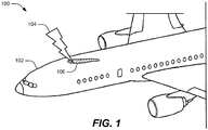
- the aircraft 100 may include composite materials, metallic materials, other types of building materials, or combinations thereof.
- a surface 102 of the aircraft 100 may include a thermo-chromatic witness material applied thereto as described herein.
- the surface 102 of the aircraft 100 may get struck by lightning 104.
- the thermo-chromatic witness material may change color creating a color changed region 106 of the surface 102.
- the color changed region 106 may substantially follow the pathway of the electrical current until the electrical current leaves the surface 102 of the aircraft 100 or dissipates such that it no longer generates sufficient heat to activate the thermo-chromatic witness material.
- the thermo-chromatic material is selected such that the color changed region 106 may be visible under ultraviolet light and may be substantially invisible under non-ultraviolet light.
- thermo-chromatic witness material to the surface 102 of the aircraft is that it enables detection of both the strike point of the lightning 104 and the pathway taken by the electrical current through the surface 102 of the aircraft 100.
- a more accurate estimation may be made of which components may have been damaged due to the lightning 104.
- time and expense may be saved by inspecting only those components proximate to the color changed region 106, as those components are more likely to have been overheated or otherwise damages by the electrical current.
- Other benefits and advantages associated with the embodiment of FIG. 1 may be apparent to persons of ordinary skill in the relevant art having the benefit of this disclosure.
- FIGS. 2 and 2A an embodiment of a system 200 for lightning strike indication is depicted.
- FIG. 2 depicts a top view of the system 200.
- FIG. 2A depicts a cross-section view of the system 200 along the cross-section line designated by the symbol A of FIG. 2 .
- the system 200 may include a thermo-chromatic witness material 202 applied to a structure 204.
- thermo-chromatic witness material 202 may include any substance that changes color due to a change in temperature. For lightning detection applications, the color change may be sufficiently permanent to remain changed until inspection of the system 200 may take place. In some embodiments, the thermo-chromatic witness material 202 may change color or fluoresce at a threshold temperature between 200 °C and 300 °C.
- thermo-chromatic witness materials may be associated with different time intervals during which heat is applied in order to activate.
- the thermo-chromatic witness material 202 in order to detect lightning strikes, is activated during the short time interval associated with a lightning strike.
- the thermo-chromatic witness material 202 may activate within a time period between 0.1 second and 1 second.
- the thermo-chromatic witness material 202 may retain its changed color for a sufficient time interval to enable inspection of the system 200.
- the thermo-chromatic witness material may retain its changed color for up to several days or longer.
- the structure 204 may include any structure for which lightning strike protection may be desirable.
- the structure 204 may be a portion of an aircraft.
- the structure 204 may include a copper foil applied to a composite aircraft, a conductive mesh of a composite aircraft, a dielectric top of a composite aircraft, a lightning diversion strip, a grounding cable or plate, a portion of a lightning protection layer of an aircraft, another portion of an aircraft, or combinations thereof.
- the system 200 may be struck by lightning.
- the lightning may generate an electrical current that enters the structure 204 at an entrance point 210.
- the current may travel through the structure 204 along a pathway 208 before exiting through an exit point 212.
- the electrical current may dissipate, either partially or entirely, along the pathway 208.
- the structure 204 may be designed to redirect and/or spread the electrical current over a large area resulting in a reduction of the electrical current.
- the electrical current may be completely dissipated before reaching the exit point 212.
- thermo-chromatic witness material 202 applied at the portion 206 may change to another color, forming a color changed region 214.
- the hatching shown in FIG. 2 and 2A indicate that a color of the color changed region 214 differs from the rest of the thermo-chromatic witness material 202.
- thermo-chromatic witness material 202 An advantage of the system 200 is that by forming a color change region 214 in the thermo-chromatic witness material 202, the system 200 provides a quick, reliable, and non-invasive method for determining a pathway taken by current from the lightning strike through the structure 204, and for determining the extent to which components along the pathway 208 may have been damaged. Other benefits and advantages of the system 200 may be apparent to persons of ordinary skill in the relevant art having the benefit of this disclosure.
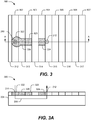
- the system 300 may include a first set of applique strips 302-307 and a second set of applique strips 312-317.
- the first set of applique strips 302-307 may include a first thermo-chromatic witness material that changes color at a first threshold temperature.
- the second set of applique strips 312-317 may include a second thermo-chromatic witness material that changes color at a second threshold temperature that is greater than the first threshold temperature.
- the electrical current passing through the structure 204 may be the most intense near the entrance point 210. As it travels along the pathway 208, it may lose power as it heats the structure 204 and/or dissipates through a large conductive area. As such, the structure 204 may be heated to higher temperatures along the pathway 208 near the entrance point 210 as compared to near the exit point 212.
- the electrical current may heat portions of the structure 204 in contact with some of the applique strips (e.g., the applique strips 302-304) to a temperature beyond the first threshold temperature.
- the first thermo-chromatic witness material included in the applique strips 302-304 may change color to form color changed regions 322-324 over the heated portions of the structure 204.
- the current may heat other portions of the structure 204 in contact with other applique strips (e.g., the applique strips 313-315). Near the entrance point 210, the heat may exceed the second threshold temperature causing the second thermo-chromatic witness material included in the applique strip 313 to change color to form another color change region 326.
- the heat generated by the electrical current may decrease. As such, further from the entrance point 210, the heat may not exceed the second threshold temperature, resulting in the formation of no color change regions within some of the applique strips (e.g., the applique strips 314, 315) despite being in contact with heated portions of the structure 204.
- thermo-chromatic witness material By including a first thermo-chromatic witness material in some of the applique strips and including another thermo-chromatic witness material in other applique strips, a determination may be made of the extent of heating within the structure 204 at multiple portions of the structure 204 along the pathway 208. For example, a determination may be made that the portions of the structure 204 that are adjacent to the applique strips 302, 303, and 313 may have been subjected to more heating than the portions of the structure 204 adjacent to the applique strips 304, 314, 315 because the temperatures near the applique strip 313 exceeded the second threshold temperature while the temperatures near the applique strips 314, 315 did not exceed the second threshold temperature.
- thermo-chromatic witness material and the second thermo-chromatic witness material may be distinct from each other after their respective threshold temperatures are reached in order to enable a determination of temperature ranged reached at each portion of the structure 204.
- the applique strips 302-307 that include the first thermo-chromatic witness material and the applique strips 312-317 that include the second thermo-chromatic witness material may be alternately applied to produce an even heat sampling for both temperature thresholds across the structure 204.
- more than two types of thermo-chromatic witness materials may be used.
- additional applique strips including additional thermo-chromatic witness materials may be applied to additional portions of the structure 204.
- the additional thermo-chromatic witness materials may be successively adapted to change to additional colors in response to heating of the additional portions of the structure 204 to additional successively increasing threshold temperatures.
- the additional applique strips may be sequentially laid along the structure 204 to produce an even heat sampling for each temperature threshold.
- each of the thermo-chromatic witness materials may change to colors distinct from each other. As such, a range of temperatures experienced by the structure 204 may be mapped.
- thermo-chromatic witness material An advantage associated with alternating between applique strips that include a first thermo-chromatic witness material and applique strips that include a second thermo-chromatic witness material is that the system 300 may provide a quick, reliable, and non-invasive method for determining the pathway 208 taken by current from a lightning strike through the structure 204, and for determining the extent to which components along the pathway 208 may have been damaged. Further, because the system 300 incorporates applique strips, it may be easily constructed. Other benefits and advantages of the system 300 may be apparent to persons of ordinary skill in the relevant art having the benefit of this disclosure.
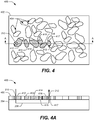
- the system 400 may include a matrix material 402 applied to the structure 204 with multiple thermo-chromatic witness particles 404 incorporated therein.
- the matrix material 402 may include a resin or another type of coating applied to the structure 204.
- the matrix material 402 may be applied to the structure 204 by spraying, brushing, another type of application process, or combinations thereof.
- the thermo-chromatic witness particles 404 may be incorporated into the matrix material 402 before application of the matrix material 402 to the structure 204. Alternatively, in some embodiments, the thermo-chromatic witness particles 404 may be incorporated into the matrix material 402 after the application thereof.
- thermo-chromatic witness particles 404 may include a first thermo-chromatic witness material and some of the thermo-chromatic witness particles 404 may include a second thermo-chromatic witness material.
- the first thermo-chromatic witness material may change to a first color when heated to a first threshold temperature and the second thermo-chromatic witness material may change to a second color, distinct from the first color, when heated to a second threshold temperature, different than the first threshold temperature.
- some of the particles 404 may change to a first color forming color changed regions (e.g., the color changed regions 412, 414, 417) of the particles.
- Other color changed regions e.g., the color changed regions 413, 415) may correspond to a second color distinct from the first.
- the particles 404 are mixed into the matrix material 402 haphazardly.
- the first set of particles 412, 414, 416, 417 are incorporated into a first portion of the matrix material 402 and the second set of particles 413, 415 are incorporated into a second portion of the matrix material 402, with the first and second portions initially separated.
- Each portion of the matrix material 402 may then be applied to the structure 204 in a pattern.
- some of the particles 404 include additional thermo-chromatic witness materials that change to additional colors, distinct from the first color and second color and distinct from each other, in response to heating of the additional portions of the structure 204 to additional successively increasing threshold.
- thermo-chromatic witness particles 404 may change color based on a temperature range associated with a respective thermo-chromatic witness particles material. The change in color may enable a determination of the position of potential damage to the structure 204 and/or the extent of damage.
- the system 500 may include a controller 502, a light source 506, and a detector 508.
- the controller 502 may perform control functions as described herein.
- the controller is implemented using a processor and memory.
- the processor may include a central processing unit (CPU), a graphical processing unit (GPU), a peripheral interface controller (PIC), another type of processing unit, or combinations thereof.
- the controller is implemented using programmable or fixed circuit logic such as a field programmable gate array (FPGA), an application specific integrated circuit (ASIC), an integrated circuit (IC) device, another type of circuit logic, or combinations thereof.
- FPGA field programmable gate array
- ASIC application specific integrated circuit
- IC integrated circuit
- the controller 502 may include a position determination module 504 that receives input from the detector 508. Based on the input, the position determination module 504 may determine a position of the color changed region 214. The controller 502 may further include a damage assessment module 505 that determines the extent of potential damage to the structure 204 at the position. In some embodiments, the controller may generate a visual depiction that maps the position and an estimate of the extent of potential damage to a three-dimensional model of the structure 204.
- the light source 506 may be directed at the structure 204.
- the light source 506 may include an ultraviolet light lamp.
- the light source 506 may emit light 510 (e.g. ultraviolet light) which may cause the thermo-chromatic witness material 202 to fluoresce. Reflected and/or additional light 511 showing the fluoresced thermo-chromatic witness material may be received at the detector 508.
- the detector may send image data based on the light 511 to the position determination module 504.
- the controller 502 may control the detector 508 to scan a surface of the thermo-chromatic witness material 202.
- the detector 508 may scan in the direction indicated by the arrow 512. Scanning may include rotational movements, translational movements, other types of movements, or combinations thereof.
- the controller 502 may include gears, motors, or other mechanical devices (not shown) to apply movement to the detector 508.
- the controller 502 may locate the position of the color changed region 214. Further, the controller 505 may analyze the colors present at the color changed region 214 to determine the extent of heating of the structure 204 throughout each position of the structure 204 and thereby generate an estimate of damage that may have occurred at one or more components of the structure 204.
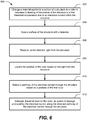
- the method 600 may include changing a material applied to a portion of a structure to a color in response to heating of the portion of the structure to a first threshold temperature due to an electrical current within the structure, at 602.
- the thermo-chromatic witness material 202 may change to the color represented by the hatching of FIG. 2 at the color changed region 214 in response to heating of the portion 206 of the structure 204 proximate to the electrical current path 208.
- the method 600 may further include scanning a surface of the structure with a detector, at 604.
- the surface of the structure 204 may be scanned by the detector 508.
- the method 600 may also include receiving, at the detector, light from the structure, at 606.
- the light 511 may be received at the detector 508.
- the method 600 may include locating the position of the color based on the light from the structure receiving, at the detector, light from the structure, at 608. For example, the position of the color changed region 214 may be determined at the position determination module 504.
- the method 600 may further include detecting a pathway of the electrical current through the structure based on a position of the first color, at 610.
- the pathway 208 may be detected based on the pathway of the color changed region 214.
- the method 600 may also include estimating, based at least on the color, an extent of damage produced by the electrical current along the detected pathway of the electrical current through the structure, at 612.
- the damage assessment module 505 may determine an extent of damage along the color changed region 214 based on the color of the color changed region 214.
- the method 700 may include applying a first material to a first portion of a structure, at 702.
- the first material may adapted to change to a first color in response to heating of the first portion of the structure to a first threshold temperature due to an electrical current within the structure.
- the applique strips 302-307 may be applied to the structure 204.
- the chromatic witness particles 412, 414, 416, 417 may be applied to the structure 204.
- the method 700 may further include applying a second material to a second portion of the structure, at 704.
- the second material may be adapted to change to a second color, distinct from the first color, in response to heating of the second portion of the structure to a second threshold temperature.
- the applique strips 312-217 may be applied to the structure 204.
- the chromatic witness particles 413, 415 may be applied to the structure 204.
Landscapes
- Physics & Mathematics (AREA)
- General Physics & Mathematics (AREA)
- Health & Medical Sciences (AREA)
- Chemical & Material Sciences (AREA)
- Life Sciences & Earth Sciences (AREA)
- Immunology (AREA)
- Pathology (AREA)
- Analytical Chemistry (AREA)
- Biochemistry (AREA)
- General Health & Medical Sciences (AREA)
- Spectroscopy & Molecular Physics (AREA)
- Aviation & Aerospace Engineering (AREA)
- Engineering & Computer Science (AREA)
- Nuclear Medicine, Radiotherapy & Molecular Imaging (AREA)
- Inorganic Chemistry (AREA)
- Investigating Or Analyzing Materials Using Thermal Means (AREA)
- Investigating, Analyzing Materials By Fluorescence Or Luminescence (AREA)
- Investigating Or Analysing Materials By Optical Means (AREA)
- Laminated Bodies (AREA)
- Radiation Pyrometers (AREA)
Abstract
Description
- This disclosure is generally related to thermo-chromatic witness features for lightning strike indication in both metallic and composite structures.
- With the increasing use of carbon fiber reinforced polymer (CFRP) composite structures in the aerospace and commercial aircraft industry, there is an increasing need for the advancement of efficient non-destructive evaluation (NDE) methods for the detection of composite damage. An especially dangerous form of damage results from lightning strike, which can induce thermal damage that is difficult to detect.
- Typical inspection methods for thermal damage due to lightning strikes may include using ultrasonic instrumentation to determine whether damage, such as delamination, separation, and/or cracking, has occurred. Another method of inspection includes performing a Fourier transform infrared (FTIR) analysis of a spectral signal taken from the aircraft to correlate a visual inspection to heat damage for specific resin coatings. However, these methods are time consuming and may be inaccurate.
- Other methods for detecting damage due to lightning strikes may involve determining a position of an initial strike point based on marks, discoloration, or damage caused by the initial lightning strike, and inspecting each component of the aircraft in proximity to the initial strike point. However, many of the components inspected may fall outside of a particular pathway followed by the electrical current from the lightning strike and are therefore unlikely to have been damaged. Because it is unknown which pathway the current may have taken, these components may be needlessly inspected. The inspections may also include time-consuming, expensive, and/or invasive dismantling processes. What is needed is a quick, reliable, and non-invasive method for determining a pathway taken by current from a lightning strike through a structure, and for determining the extent to which components along the pathway may have been damaged.
- In an embodiment, a system includes a structure and a thermo-chromatic material applied to the structure. The thermo-chromatic material is adapted to change to a color locally in response to localized heating of the structure. The heating may be caused by an electrical current from a lightning strike. By examining the position and extent of the color change, an estimation of damage to the structure due to the lightning strike may be determined.
- In an embodiment, a method includes changing a material applied to a portion of a structure to a first color in response to heating of the portion of the structure to a first threshold temperature due to an electrical current within the structure. The method further includes detecting a pathway of the electrical current through the structure based on a position of the first color.
- In some embodiments, the method also includes estimating, based at least on the first color, an extent of damage produced by the electrical current along the detected pathway of the electrical current through the structure. In some embodiments, the method includes changing a material applied to a second portion of the structure to a second color distinct from the first color in response to heating of the second portion of the structure to a second threshold temperature greater than the first threshold temperature. In some embodiments, the method includes successively changing additional materials applied to additional portions of the structure to additional colors distinct from the first color and distinct from each other in response to heating of the additional portions of the structure to additional successively increasing threshold. In some embodiments, the method includes estimating, based at least on the first color and the additional colors, an extent of damage produced by the electrical current along the detected pathway of the electrical current through the structure.
- In some embodiments, the method includes scanning a surface of the structure with a detector. The method further includes receiving, at the detector, light from the structure. The method also includes locating the position of the first color based on the light from the structure. In some embodiments, the method includes directing a light source at the structure during the scanning. The light source may be an ultraviolet light source and the first color may be substantially invisible under non-ultraviolet light. In some embodiments, the first threshold temperature is between 200 °C and 300 °C.
- In an embodiment, a system includes a structure and a first material applied to a portion of the structure. The material is adapted to change to a first color locally in response to localized heating of the portion of the structure to a first threshold temperature due to an electrical current within the structure. The system further includes a detector configured to receive light from the structure to enable detection of a pathway of the electrical current through the structure based on a position of the first color.
- In some embodiments, the first color enables estimating an extent of damage produced by the electrical current along the pathway of the electrical current through the structure. In some embodiments, the system further includes a second material applied to a second portion of the structure. The second material is adapted to change to a second color, distinct from the first color, in response to heating of the portion of the structure to a second threshold temperature greater than the first threshold temperature. In some embodiments, the system also includes additional materials applied to additional portions of the structure. The additional materials are adapted to change to additional colors, distinct from the first color and distinct from each other, in response to heating of the additional portions of the structure to additional successively increasing threshold temperatures. In some embodiments, the first color and the additional colors enable estimating an extent of damage produced by the electrical current along the detected pathway of the electrical current through the structure.
- In some embodiments, the system also includes a light source directed toward the structure. The light source may be an ultraviolet light source and the first color may be substantially invisible under non-ultraviolet light.
- In some embodiments, the structure includes a copper foil applied to a composite aircraft, a conductive mesh of a composite aircraft, a dielectric top of a composite aircraft, a lightning diversion strip, a grounding cable or plate, a portion of a lightning protection layer of an aircraft, or any combination thereof. In some embodiments, the material includes a thermo-chromatic witness material.
- In an embodiment, a method includes applying a first material to a first portion of a structure. The first material is adapted to change to a first color in response to heating of the first portion of the structure to a first threshold temperature due to an electrical current within the structure. The method further includes applying a second material to a second portion of the structure. The second material is adapted to change to a second color, distinct from the first color, in response to heating of the second portion of the structure to a second threshold temperature.
- In some embodiments, the first material is incorporated into a first set of applique strips and the second material is incorporated into a second set of applique strips. The first set of applique strips and the second set of applique strips are applied to the structure in a repeating pattern. In some embodiments, the first material is incorporated into a first portion of a coating matrix and the second material is incorporated into a second portion of coating matrix. The coating matrix is applied to the structure. In some embodiments, the first material is incorporated into a first portion of a resin of a lightning protection layer and the second material is incorporated into a second portion of the resin of the lightning protection layer.
-
-
FIG. 1 depicts an embodiment of anaircraft 100 with a thermo-chromatic material. -
FIG. 2 depicts an embodiment of a system for lightning strike indication. -
FIG. 2A depicts a cross-section view of the embodiment of the system for lightning strike indication. -
FIG. 3 depicts an embodiment of a system for lightning strike indication. -
FIG. 3A depicts a cross-section view of the embodiment of the system for lightning strike indication. -
FIG. 4 depicts an embodiment of a system for lightning strike indication. -
FIG. 4A depicts a cross-section view of the embodiment of the system for lightning strike indication. -
FIG. 5 depicts an embodiment of a system for detecting a position and the extent of potential damage due to lightning strikes. -
FIG. 6 is a flowchart that depicts an embodiment of a method for lightning strike indication. -
FIG. 7 is a flowchart that depicts an embodiment of a method for making a lightning strike indication system. - While the disclosure is susceptible to various modifications and alternative forms, specific embodiments have been shown by way of example in the drawings and will be described in detail herein. However, it should be understood that the disclosure is not intended to be limited to the particular forms disclosed. Rather, the intention is to cover all modifications, equivalents and alternatives falling within the spirit and scope of the disclosure as defined by the appended claims.
- Referring to
FIG. 1 , an embodiment of anaircraft 100 is depicted. Theaircraft 100 may include composite materials, metallic materials, other types of building materials, or combinations thereof. Asurface 102 of theaircraft 100 may include a thermo-chromatic witness material applied thereto as described herein. At some time during the operations of theaircraft 100, thesurface 102 of theaircraft 100 may get struck bylightning 104. In response to heat generated within the structure of theaircraft 100, the thermo-chromatic witness material may change color creating a color changedregion 106 of thesurface 102. Because the color changedregion 106 is formed due to heat generated by electrical current from thelightning 104, the color changedregion 106 may substantially follow the pathway of the electrical current until the electrical current leaves thesurface 102 of theaircraft 100 or dissipates such that it no longer generates sufficient heat to activate the thermo-chromatic witness material. In some embodiments, the thermo-chromatic material is selected such that the color changedregion 106 may be visible under ultraviolet light and may be substantially invisible under non-ultraviolet light. - An advantage of applying the thermo-chromatic witness material to the
surface 102 of the aircraft is that it enables detection of both the strike point of thelightning 104 and the pathway taken by the electrical current through thesurface 102 of theaircraft 100. By locating the position of the color changedregion 106, a more accurate estimation may be made of which components may have been damaged due to thelightning 104. Thus, time and expense may be saved by inspecting only those components proximate to the color changedregion 106, as those components are more likely to have been overheated or otherwise damages by the electrical current. Other benefits and advantages associated with the embodiment ofFIG. 1 may be apparent to persons of ordinary skill in the relevant art having the benefit of this disclosure. - Referring to
FIGS. 2 and 2A , an embodiment of asystem 200 for lightning strike indication is depicted.FIG. 2 depicts a top view of thesystem 200.FIG. 2A depicts a cross-section view of thesystem 200 along the cross-section line designated by the symbol A ofFIG. 2 . Thesystem 200 may include a thermo-chromatic witness material 202 applied to astructure 204. - The thermo-
chromatic witness material 202 may include any substance that changes color due to a change in temperature. For lightning detection applications, the color change may be sufficiently permanent to remain changed until inspection of thesystem 200 may take place. In some embodiments, the thermo-chromatic witness material 202 may change color or fluoresce at a threshold temperature between 200 °C and 300 °C. - Different types of thermo-chromatic witness materials may be associated with different time intervals during which heat is applied in order to activate. In some embodiments, in order to detect lightning strikes, the thermo-
chromatic witness material 202 is activated during the short time interval associated with a lightning strike. For example, the thermo-chromatic witness material 202 may activate within a time period between 0.1 second and 1 second. Further, the thermo-chromatic witness material 202 may retain its changed color for a sufficient time interval to enable inspection of thesystem 200. For example the thermo-chromatic witness material may retain its changed color for up to several days or longer. - The
structure 204 may include any structure for which lightning strike protection may be desirable. In some embodiments, thestructure 204 may be a portion of an aircraft. For example, thestructure 204 may include a copper foil applied to a composite aircraft, a conductive mesh of a composite aircraft, a dielectric top of a composite aircraft, a lightning diversion strip, a grounding cable or plate, a portion of a lightning protection layer of an aircraft, another portion of an aircraft, or combinations thereof. - At some time during operation, the
system 200 may be struck by lightning. The lightning may generate an electrical current that enters thestructure 204 at anentrance point 210. The current may travel through thestructure 204 along apathway 208 before exiting through anexit point 212. In some embodiments, the electrical current may dissipate, either partially or entirely, along thepathway 208. For example, thestructure 204 may be designed to redirect and/or spread the electrical current over a large area resulting in a reduction of the electrical current. In some instances, the electrical current may be completely dissipated before reaching theexit point 212. - As the electrical current moves through the
structure 204 along thepathway 208, aportion 206 of thestructure 204 in proximity to the pathway may become heated. When theportion 206 reaches a threshold temperature, the thermo-chromatic witness material 202 applied at theportion 206 may change to another color, forming a color changedregion 214. The hatching shown inFIG. 2 and 2A indicate that a color of the color changedregion 214 differs from the rest of the thermo-chromatic witness material 202. - An advantage of the
system 200 is that by forming acolor change region 214 in the thermo-chromatic witness material 202, thesystem 200 provides a quick, reliable, and non-invasive method for determining a pathway taken by current from the lightning strike through thestructure 204, and for determining the extent to which components along thepathway 208 may have been damaged. Other benefits and advantages of thesystem 200 may be apparent to persons of ordinary skill in the relevant art having the benefit of this disclosure. - Referring to
FIGS. 3 and 3A , an embodiment of asystem 300 for lightning strike indication is depicted. Thesystem 300 may include a first set of applique strips 302-307 and a second set of applique strips 312-317. The first set of applique strips 302-307 may include a first thermo-chromatic witness material that changes color at a first threshold temperature. The second set of applique strips 312-317 may include a second thermo-chromatic witness material that changes color at a second threshold temperature that is greater than the first threshold temperature. - The electrical current passing through the
structure 204 may be the most intense near theentrance point 210. As it travels along thepathway 208, it may lose power as it heats thestructure 204 and/or dissipates through a large conductive area. As such, thestructure 204 may be heated to higher temperatures along thepathway 208 near theentrance point 210 as compared to near theexit point 212. - As depicted in
FIGS. 3 and 3A , the electrical current may heat portions of thestructure 204 in contact with some of the applique strips (e.g., the applique strips 302-304) to a temperature beyond the first threshold temperature. In response to the heat, the first thermo-chromatic witness material included in the applique strips 302-304 may change color to form color changed regions 322-324 over the heated portions of thestructure 204. Likewise, the current may heat other portions of thestructure 204 in contact with other applique strips (e.g., the applique strips 313-315). Near theentrance point 210, the heat may exceed the second threshold temperature causing the second thermo-chromatic witness material included in theapplique strip 313 to change color to form anothercolor change region 326. As thepathway 208 moves away from theentrance point 210, the heat generated by the electrical current may decrease. As such, further from theentrance point 210, the heat may not exceed the second threshold temperature, resulting in the formation of no color change regions within some of the applique strips (e.g., the applique strips 314, 315) despite being in contact with heated portions of thestructure 204. - By including a first thermo-chromatic witness material in some of the applique strips and including another thermo-chromatic witness material in other applique strips, a determination may be made of the extent of heating within the
structure 204 at multiple portions of thestructure 204 along thepathway 208. For example, a determination may be made that the portions of thestructure 204 that are adjacent to the applique strips 302, 303, and 313 may have been subjected to more heating than the portions of thestructure 204 adjacent to the applique strips 304, 314, 315 because the temperatures near theapplique strip 313 exceeded the second threshold temperature while the temperatures near the applique strips 314, 315 did not exceed the second threshold temperature. Thus, components within thestructure 204 near the applique strips 302, 303, 313 may have been subjected to more heat and consequently may be more likely to have been damaged by the lightning strike. Colors of the first thermo-chromatic witness material and the second thermo-chromatic witness material may be distinct from each other after their respective threshold temperatures are reached in order to enable a determination of temperature ranged reached at each portion of thestructure 204. - As shown in
FIG. 3 , the applique strips 302-307 that include the first thermo-chromatic witness material and the applique strips 312-317 that include the second thermo-chromatic witness material may be alternately applied to produce an even heat sampling for both temperature thresholds across thestructure 204. In some embodiments, more than two types of thermo-chromatic witness materials may be used. For example, additional applique strips including additional thermo-chromatic witness materials may be applied to additional portions of thestructure 204. The additional thermo-chromatic witness materials may be successively adapted to change to additional colors in response to heating of the additional portions of thestructure 204 to additional successively increasing threshold temperatures. The additional applique strips may be sequentially laid along thestructure 204 to produce an even heat sampling for each temperature threshold. Further, each of the thermo-chromatic witness materials may change to colors distinct from each other. As such, a range of temperatures experienced by thestructure 204 may be mapped. - An advantage associated with alternating between applique strips that include a first thermo-chromatic witness material and applique strips that include a second thermo-chromatic witness material is that the
system 300 may provide a quick, reliable, and non-invasive method for determining thepathway 208 taken by current from a lightning strike through thestructure 204, and for determining the extent to which components along thepathway 208 may have been damaged. Further, because thesystem 300 incorporates applique strips, it may be easily constructed. Other benefits and advantages of thesystem 300 may be apparent to persons of ordinary skill in the relevant art having the benefit of this disclosure. - Referring to
FIGS. 4 and 4A , an embodiment of asystem 400 for lightning strike indication is depicted. Thesystem 400 may include amatrix material 402 applied to thestructure 204 with multiple thermo-chromatic witness particles 404 incorporated therein. - In some embodiments, the
matrix material 402 may include a resin or another type of coating applied to thestructure 204. Thematrix material 402 may be applied to thestructure 204 by spraying, brushing, another type of application process, or combinations thereof. The thermo-chromatic witness particles 404 may be incorporated into thematrix material 402 before application of thematrix material 402 to thestructure 204. Alternatively, in some embodiments, the thermo-chromatic witness particles 404 may be incorporated into thematrix material 402 after the application thereof. - Some of the thermo-
chromatic witness particles 404 may include a first thermo-chromatic witness material and some of the thermo-chromatic witness particles 404 may include a second thermo-chromatic witness material. The first thermo-chromatic witness material may change to a first color when heated to a first threshold temperature and the second thermo-chromatic witness material may change to a second color, distinct from the first color, when heated to a second threshold temperature, different than the first threshold temperature. For example, upon heating due to the current along thepathway 208, some of theparticles 404 may change to a first color forming color changed regions (e.g., the color changedregions regions 413, 415) may correspond to a second color distinct from the first. - In some embodiments, as depicted in
FIGS. 4 and 4A , theparticles 404 are mixed into thematrix material 402 haphazardly. Alternatively, in some embodiments, the first set ofparticles matrix material 402 and the second set ofparticles matrix material 402, with the first and second portions initially separated. Each portion of thematrix material 402 may then be applied to thestructure 204 in a pattern. Although not depicted inFIG. 4 , in some embodiments, some of theparticles 404 include additional thermo-chromatic witness materials that change to additional colors, distinct from the first color and second color and distinct from each other, in response to heating of the additional portions of thestructure 204 to additional successively increasing threshold. - As electrical current passes from the
entrance point 210 to theexit point 212 along thepathway 208, it may heat thestructure 204. If portions of thestructure 204 are heated beyond the first threshold temperature, then the thermo-chromatic witness particles 404 may change color based on a temperature range associated with a respective thermo-chromatic witness particles material. The change in color may enable a determination of the position of potential damage to thestructure 204 and/or the extent of damage. Other benefits and advantages of thesystem 400 may be apparent to persons of ordinary skill in the relevant art having the benefit of this disclosure. - Referring to
FIG. 5 , an embodiment of asystem 500 for detecting a position and the extent of potential damage due to lightning strikes is depicted. Thesystem 500 may include acontroller 502, alight source 506, and adetector 508. - The
controller 502 may perform control functions as described herein. In some embodiments, the controller is implemented using a processor and memory. For example, the processor may include a central processing unit (CPU), a graphical processing unit (GPU), a peripheral interface controller (PIC), another type of processing unit, or combinations thereof. In some embodiments, the controller is implemented using programmable or fixed circuit logic such as a field programmable gate array (FPGA), an application specific integrated circuit (ASIC), an integrated circuit (IC) device, another type of circuit logic, or combinations thereof. - The
controller 502 may include aposition determination module 504 that receives input from thedetector 508. Based on the input, theposition determination module 504 may determine a position of the color changedregion 214. Thecontroller 502 may further include adamage assessment module 505 that determines the extent of potential damage to thestructure 204 at the position. In some embodiments, the controller may generate a visual depiction that maps the position and an estimate of the extent of potential damage to a three-dimensional model of thestructure 204. - During operation, the
light source 506 may be directed at thestructure 204. In some embodiments, thelight source 506 may include an ultraviolet light lamp. Thelight source 506 may emit light 510 (e.g. ultraviolet light) which may cause the thermo-chromatic witness material 202 to fluoresce. Reflected and/or additional light 511 showing the fluoresced thermo-chromatic witness material may be received at thedetector 508. The detector may send image data based on the light 511 to theposition determination module 504. - In order to determine position information, the
controller 502 may control thedetector 508 to scan a surface of the thermo-chromatic witness material 202. For example, thedetector 508 may scan in the direction indicated by thearrow 512. Scanning may include rotational movements, translational movements, other types of movements, or combinations thereof. In order to effectuate the scanning, thecontroller 502 may include gears, motors, or other mechanical devices (not shown) to apply movement to thedetector 508. - Based on the light from the
structure 204, thecontroller 502 may locate the position of the color changedregion 214. Further, thecontroller 505 may analyze the colors present at the color changedregion 214 to determine the extent of heating of thestructure 204 throughout each position of thestructure 204 and thereby generate an estimate of damage that may have occurred at one or more components of thestructure 204. - Referring to
FIG. 6 an embodiment of amethod 600 for lightning strike indication is depicted. Themethod 600 may include changing a material applied to a portion of a structure to a color in response to heating of the portion of the structure to a first threshold temperature due to an electrical current within the structure, at 602. For example, the thermo-chromatic witness material 202 may change to the color represented by the hatching ofFIG. 2 at the color changedregion 214 in response to heating of theportion 206 of thestructure 204 proximate to the electricalcurrent path 208. - The
method 600 may further include scanning a surface of the structure with a detector, at 604. For example, the surface of thestructure 204 may be scanned by thedetector 508. - The
method 600 may also include receiving, at the detector, light from the structure, at 606. For example, the light 511 may be received at thedetector 508. - The
method 600 may include locating the position of the color based on the light from the structure receiving, at the detector, light from the structure, at 608. For example, the position of the color changedregion 214 may be determined at theposition determination module 504. - The
method 600 may further include detecting a pathway of the electrical current through the structure based on a position of the first color, at 610. For example, thepathway 208 may be detected based on the pathway of the color changedregion 214. - The
method 600 may also include estimating, based at least on the color, an extent of damage produced by the electrical current along the detected pathway of the electrical current through the structure, at 612. For example, thedamage assessment module 505 may determine an extent of damage along the color changedregion 214 based on the color of the color changedregion 214. - Referring to
FIG. 7 an embodiment of amethod 700 for making a lightning strike indication system is depicted. Themethod 700 may include applying a first material to a first portion of a structure, at 702. The first material may adapted to change to a first color in response to heating of the first portion of the structure to a first threshold temperature due to an electrical current within the structure. For example, the applique strips 302-307 may be applied to thestructure 204. As another example, thechromatic witness particles structure 204. - The
method 700 may further include applying a second material to a second portion of the structure, at 704. The second material may be adapted to change to a second color, distinct from the first color, in response to heating of the second portion of the structure to a second threshold temperature. For example, the applique strips 312-217 may be applied to thestructure 204. As another example, thechromatic witness particles structure 204. - Although various embodiments have been shown and described, the present disclosure is not so limited and will be understood to include all such modifications and variations are would be apparent to one skilled in the art.
Claims (18)
- A method comprising:changing a material applied to a portion of a structure to a first color in response to heating of the portion of the structure to a first threshold temperature due to an electrical current within the structure; anddetecting a pathway of the electrical current through the structure based on a position of the first color.
- The method of claim 1, further comprising:estimating, based at least on the first color, an extent of damage produced by the electrical current along the detected pathway of the electrical current through the structure.
- The method of any of claims 1-2, further comprising:changing a material applied to a second portion of the structure to a second color distinct from the first color in response to heating of the second portion of the structure to a second threshold temperature greater than the first threshold temperature.
- The method of any of claims 1-3, further comprising:successively changing additional materials applied to additional portions of the structure to additional colors distinct from the first color and distinct from each other in response to heating of the additional portions of the structure to additional successively increasing threshold.
- The method of claim 4, further comprising:estimating, based at least on the first color and the additional colors, an extent of damage produced by the electrical current along the detected pathway of the electrical current through the structure.
- The method of any of claims 1-5, further comprising:scanning a surface of the structure with a detector;receiving, at the detector, light from the structure; andlocating the position of the first color based on the light from the structure.
- The method of claim 6, further comprising:directing a light source at the structure during the scanning, wherein the light source is an ultraviolet light source, and wherein the first color is substantially invisible under non-ultraviolet light.
- A system comprising:a structure;a first material applied to a first portion of the structure, the material adapted to change to a first color locally in response to localized heating of the first portion of the structure to a first threshold temperature due to an electrical current within the structure; anda detector configured to receive light from the structure to enable detection of a pathway of the electrical current through the structure based on a position of the first color.
- The system of claim 8, wherein the first color enables estimating an extent of damage produced by the electrical current along the pathway of the electrical current through the structure.
- The system of any of claims 8-9, further comprising:a second material applied to a second portion of the structure, the second material adapted to change to a second color, distinct from the first color, in response to heating of the second portion of the structure to a second threshold temperature greater than the first threshold temperature.
- The system of any of claims 8-10, further comprising:additional materials applied to additional portions of the structure, the additional materials adapted to change to additional colors, distinct from the first color and distinct from each other, in response to heating of the additional portions of the structure to additional successively increasing threshold temperatures.
- The system of claim 11, wherein the first color and the additional colors enable estimating an extent of damage produced by the electrical current along the detected pathway of the electrical current through the structure.
- The system of any of claims 8-12, further comprising:a light source directed toward the structure, wherein the light source is an ultraviolet light source, and wherein the first color is substantially invisible under non-ultraviolet light.
- The system of any of claims 8-13, wherein the structure includes a copper foil applied to a composite aircraft, a conductive mesh of a composite aircraft, a dielectric top of a composite aircraft, a lightning diversion strip, a grounding cable or plate, a portion of a lightning protection layer of an aircraft, or any combination thereof.
- A method comprising:applying a first material to a first portion of a structure, wherein the first material is adapted to change to a first color in response to heating of the first portion of the structure to a first threshold temperature due to an electrical current within the structure;applying a second material to a second portion of the structure, wherein the second material is adapted to change to a second color, distinct from the first color, in response to heating of the second portion of the structure to a second threshold temperature.
- The method of claim 15, wherein the first material is incorporated into a first set of applique strips and the second material is incorporated into a second set of applique strips, and wherein the first set of applique strips and the second set of applique strips are applied to the structure in a repeating pattern.
- The method of any of claims 15-16, wherein the first material is incorporated into a first portion of a coating matrix and the second material is incorporated into a second portion of coating matrix, wherein the coating matrix is applied to the structure.
- The method of any of claims 15-17, wherein the first material is incorporated into a first portion of a resin of a lightning protection layer and wherein the second material is incorporated into a second portion of the resin of the lightning protection layer.
Applications Claiming Priority (1)
| Application Number | Priority Date | Filing Date | Title |
|---|---|---|---|
| US15/143,958 US10416103B2 (en) | 2016-05-02 | 2016-05-02 | Thermo-chromatic witness features for lightning strike indication in both metallic and composite structures |
Publications (2)
| Publication Number | Publication Date |
|---|---|
| EP3241759A1 true EP3241759A1 (en) | 2017-11-08 |
| EP3241759B1 EP3241759B1 (en) | 2023-05-03 |
Family
ID=58358358
Family Applications (1)
| Application Number | Title | Priority Date | Filing Date |
|---|---|---|---|
| EP17160690.8A Active EP3241759B1 (en) | 2016-05-02 | 2017-03-13 | Thermo-chromatic witness features for lightning strike indication in both metallic and composite structures |
Country Status (8)
| Country | Link |
|---|---|
| US (2) | US10416103B2 (en) |
| EP (1) | EP3241759B1 (en) |
| JP (1) | JP6935221B2 (en) |
| KR (1) | KR102328620B1 (en) |
| CN (1) | CN107340303B (en) |
| AU (1) | AU2017201710B2 (en) |
| BR (1) | BR102017008688B1 (en) |
| CA (1) | CA2964400C (en) |
Families Citing this family (1)
| Publication number | Priority date | Publication date | Assignee | Title |
|---|---|---|---|---|
| ES2783623T3 (en) * | 2016-07-18 | 2020-09-17 | Airbus Operations Sl | Method and device for the inspection of damage to the skin of an aircraft after a lightning strike |
Citations (3)
| Publication number | Priority date | Publication date | Assignee | Title |
|---|---|---|---|---|
| EP2778661A2 (en) * | 2013-03-15 | 2014-09-17 | The Boeing Company | Method and system for detecting exposure of composites to high-temperature |
| CN102618254B (en) * | 2012-03-16 | 2014-12-31 | 苏州大学 | Electrochromic composite material and preparation method thereof |
| US9346559B1 (en) * | 2015-01-05 | 2016-05-24 | Grady L. Skelton | Aeronautical static discharge device and indicator therein |
Family Cites Families (13)
| Publication number | Priority date | Publication date | Assignee | Title |
|---|---|---|---|---|
| JPS4925519B1 (en) * | 1969-04-08 | 1974-07-01 | ||
| US4500294A (en) * | 1983-10-03 | 1985-02-19 | Epic International Corporation | Method and device for detecting dental cavities |
| JPS6415645A (en) * | 1987-07-10 | 1989-01-19 | Hitachi Ltd | Lattice-plate inspecting apparatus |
| GB2327878B (en) * | 1997-08-04 | 2001-04-04 | Kerry Garner | Hair styling brush and method of use |
| US20080057767A1 (en) * | 2006-08-10 | 2008-03-06 | O'rourke Kevin | Electrical adaptor having an anchor |
| US7905736B2 (en) * | 2006-08-10 | 2011-03-15 | O'rourke Kevin | Temporary lighting fixture having a fastener |
| US7712431B2 (en) * | 2006-09-12 | 2010-05-11 | Roche Richard M | Thermochromic washer for monitoring performance or integrity of electrical connections |
| JP2008117958A (en) * | 2006-11-06 | 2008-05-22 | Otowa Denki Kogyo Kk | Arrester |
| CN203037808U (en) * | 2013-01-16 | 2013-07-03 | 山东大学 | Artificial lightning stroke damage testing arrangement of carbon-fiber composite |
| CN104897958B (en) * | 2014-03-07 | 2017-09-01 | 武汉三相电力科技有限公司 | A kind of discrimination method of transmission line lightning stroke type |
| CN105043458B (en) * | 2015-09-17 | 2017-07-07 | 山东大学 | A kind of fibrous composite lightning damage on-line measuring device and method |
| CN105259478B (en) * | 2015-11-18 | 2017-10-13 | 国家电网公司 | Lightning stroke flashover position identification device |
| US20180078665A1 (en) * | 2016-09-19 | 2018-03-22 | Covidien Lp | Medical package |
-
2016
- 2016-05-02 US US15/143,958 patent/US10416103B2/en active Active
-
2017
- 2017-03-13 EP EP17160690.8A patent/EP3241759B1/en active Active
- 2017-03-13 AU AU2017201710A patent/AU2017201710B2/en active Active
- 2017-04-12 CA CA2964400A patent/CA2964400C/en active Active
- 2017-04-18 JP JP2017081811A patent/JP6935221B2/en active Active
- 2017-04-19 CN CN201710256657.8A patent/CN107340303B/en active Active
- 2017-04-24 KR KR1020170052384A patent/KR102328620B1/en active Active
- 2017-04-26 BR BR102017008688-7A patent/BR102017008688B1/en active IP Right Grant
-
2019
- 2019-09-16 US US16/571,963 patent/US10775330B2/en active Active
Patent Citations (3)
| Publication number | Priority date | Publication date | Assignee | Title |
|---|---|---|---|---|
| CN102618254B (en) * | 2012-03-16 | 2014-12-31 | 苏州大学 | Electrochromic composite material and preparation method thereof |
| EP2778661A2 (en) * | 2013-03-15 | 2014-09-17 | The Boeing Company | Method and system for detecting exposure of composites to high-temperature |
| US9346559B1 (en) * | 2015-01-05 | 2016-05-24 | Grady L. Skelton | Aeronautical static discharge device and indicator therein |
Also Published As
| Publication number | Publication date |
|---|---|
| CA2964400A1 (en) | 2017-11-02 |
| AU2017201710B2 (en) | 2022-05-19 |
| US10775330B2 (en) | 2020-09-15 |
| EP3241759B1 (en) | 2023-05-03 |
| KR20170124453A (en) | 2017-11-10 |
| CN107340303B (en) | 2024-08-13 |
| JP2017227620A (en) | 2017-12-28 |
| BR102017008688A2 (en) | 2017-11-07 |
| US20170315072A1 (en) | 2017-11-02 |
| CA2964400C (en) | 2023-02-28 |
| JP6935221B2 (en) | 2021-09-15 |
| US20200011822A1 (en) | 2020-01-09 |
| US10416103B2 (en) | 2019-09-17 |
| KR102328620B1 (en) | 2021-11-18 |
| AU2017201710A1 (en) | 2017-11-16 |
| BR102017008688B1 (en) | 2022-09-27 |
| CN107340303A (en) | 2017-11-10 |
Similar Documents
| Publication | Publication Date | Title |
|---|---|---|
| RU2549913C2 (en) | Thermographic method of control and monitoring device for implementing method | |
| EP1505384A1 (en) | Method for defect detection utilizing infrared thermography | |
| US8047749B2 (en) | Rapid inspection of lightning strike protection systems prior to installing fastener | |
| US20090289624A1 (en) | Method for determining and evaluating eddy-current displays, in particular cracks, in a test object made from an electrically conductive material | |
| JP2009282027A6 (en) | A method for judging and evaluating the eddy current display of cracks in test objects made of conductive materials. | |
| JP2018197736A (en) | Defect detection device for conveyor belt | |
| EP2482067A1 (en) | A non-destructive test method for automatic fastener inspection | |
| KR101539599B1 (en) | Accelerated structural damage visualization through multi-level noncontact laser ultrasonic scanning and visualization method thereof | |
| JP5831940B2 (en) | Nondestructive inspection method and nondestructive inspection device for delamination in coating layer | |
| Ranjit et al. | Detection of Subsurface Defects in Metal Materials Using Infrared Thermography: Image Processing and Finite Element Modeling: Image Processing and Finite Element Modeling | |
| US10775330B2 (en) | Thermo-chromatic witness features for lightning strike indication in both metallic and composite structures | |
| SE1551214A1 (en) | Method and system for inspecting plate-like structures usingultrasound | |
| JP6539139B2 (en) | Image processing method for infrared image data and infrared image processing apparatus | |
| KR20170075101A (en) | Apparatus and method for steel sheet inspection | |
| US10908106B2 (en) | Coating analysis system | |
| KR101077043B1 (en) | Reference Material for Nondestructive Photo-Infrared Thermography and Inspection Method of using the same | |
| KR20170079828A (en) | Method of inspecting pattern defect | |
| JP6241402B2 (en) | Contact detection device, contact detection method, and wrinkle detector | |
| Lopato | Identification of Defects in Composite Materials Using Terahertz Inspection and Self-Organizing Maps | |
| EP2952889A1 (en) | Scratch verification apparatus and method |
Legal Events
| Date | Code | Title | Description |
|---|---|---|---|
| PUAI | Public reference made under article 153(3) epc to a published international application that has entered the european phase |
Free format text: ORIGINAL CODE: 0009012 |
|
| STAA | Information on the status of an ep patent application or granted ep patent |
Free format text: STATUS: REQUEST FOR EXAMINATION WAS MADE |
|
| 17P | Request for examination filed |
Effective date: 20170313 |
|
| AK | Designated contracting states |
Kind code of ref document: A1 Designated state(s): AL AT BE BG CH CY CZ DE DK EE ES FI FR GB GR HR HU IE IS IT LI LT LU LV MC MK MT NL NO PL PT RO RS SE SI SK SM TR |
|
| AX | Request for extension of the european patent |
Extension state: BA ME |
|
| RBV | Designated contracting states (corrected) |
Designated state(s): AL AT BE BG CH CY CZ DE DK EE ES FI FR GB GR HR HU IE IS IT LI LT LU LV MC MK MT NL NO PL PT RO RS SE SI SK SM TR |
|
| STAA | Information on the status of an ep patent application or granted ep patent |
Free format text: STATUS: EXAMINATION IS IN PROGRESS |
|
| 17Q | First examination report despatched |
Effective date: 20191115 |
|
| GRAP | Despatch of communication of intention to grant a patent |
Free format text: ORIGINAL CODE: EPIDOSNIGR1 |
|
| STAA | Information on the status of an ep patent application or granted ep patent |
Free format text: STATUS: GRANT OF PATENT IS INTENDED |
|
| GRAJ | Information related to disapproval of communication of intention to grant by the applicant or resumption of examination proceedings by the epo deleted |
Free format text: ORIGINAL CODE: EPIDOSDIGR1 |
|
| STAA | Information on the status of an ep patent application or granted ep patent |
Free format text: STATUS: EXAMINATION IS IN PROGRESS |
|
| INTG | Intention to grant announced |
Effective date: 20221004 |
|
| RIN1 | Information on inventor provided before grant (corrected) |
Inventor name: IHN, JEONG-BEOM Inventor name: GEORGESON, GARY |
|
| INTC | Intention to grant announced (deleted) | ||
| GRAP | Despatch of communication of intention to grant a patent |
Free format text: ORIGINAL CODE: EPIDOSNIGR1 |
|
| STAA | Information on the status of an ep patent application or granted ep patent |
Free format text: STATUS: GRANT OF PATENT IS INTENDED |
|
| INTG | Intention to grant announced |
Effective date: 20221124 |
|
| RIN1 | Information on inventor provided before grant (corrected) |
Inventor name: IHN, JEONG-BEOM Inventor name: GEORGESON, GARY |
|
| GRAS | Grant fee paid |
Free format text: ORIGINAL CODE: EPIDOSNIGR3 |
|
| RAP3 | Party data changed (applicant data changed or rights of an application transferred) |
Owner name: THE BOEING COMPANY |
|
| GRAA | (expected) grant |
Free format text: ORIGINAL CODE: 0009210 |
|
| STAA | Information on the status of an ep patent application or granted ep patent |
Free format text: STATUS: THE PATENT HAS BEEN GRANTED |
|
| AK | Designated contracting states |
Kind code of ref document: B1 Designated state(s): AL AT BE BG CH CY CZ DE DK EE ES FI FR GB GR HR HU IE IS IT LI LT LU LV MC MK MT NL NO PL PT RO RS SE SI SK SM TR |
|
| REG | Reference to a national code |
Ref country code: GB Ref legal event code: FG4D |
|
| REG | Reference to a national code |
Ref country code: DE Ref legal event code: R096 Ref document number: 602017068228 Country of ref document: DE |
|
| REG | Reference to a national code |
Ref country code: AT Ref legal event code: REF Ref document number: 1564411 Country of ref document: AT Kind code of ref document: T Effective date: 20230515 Ref country code: CH Ref legal event code: EP |
|
| REG | Reference to a national code |
Ref country code: IE Ref legal event code: FG4D |
|
| P01 | Opt-out of the competence of the unified patent court (upc) registered |
Effective date: 20230526 |
|
| REG | Reference to a national code |
Ref country code: LT Ref legal event code: MG9D |
|
| REG | Reference to a national code |
Ref country code: NL Ref legal event code: MP Effective date: 20230503 |
|
| REG | Reference to a national code |
Ref country code: AT Ref legal event code: MK05 Ref document number: 1564411 Country of ref document: AT Kind code of ref document: T Effective date: 20230503 |
|
| PG25 | Lapsed in a contracting state [announced via postgrant information from national office to epo] |
Ref country code: SE Free format text: LAPSE BECAUSE OF FAILURE TO SUBMIT A TRANSLATION OF THE DESCRIPTION OR TO PAY THE FEE WITHIN THE PRESCRIBED TIME-LIMIT Effective date: 20230503 Ref country code: PT Free format text: LAPSE BECAUSE OF FAILURE TO SUBMIT A TRANSLATION OF THE DESCRIPTION OR TO PAY THE FEE WITHIN THE PRESCRIBED TIME-LIMIT Effective date: 20230904 Ref country code: NO Free format text: LAPSE BECAUSE OF FAILURE TO SUBMIT A TRANSLATION OF THE DESCRIPTION OR TO PAY THE FEE WITHIN THE PRESCRIBED TIME-LIMIT Effective date: 20230803 Ref country code: NL Free format text: LAPSE BECAUSE OF FAILURE TO SUBMIT A TRANSLATION OF THE DESCRIPTION OR TO PAY THE FEE WITHIN THE PRESCRIBED TIME-LIMIT Effective date: 20230503 Ref country code: ES Free format text: LAPSE BECAUSE OF FAILURE TO SUBMIT A TRANSLATION OF THE DESCRIPTION OR TO PAY THE FEE WITHIN THE PRESCRIBED TIME-LIMIT Effective date: 20230503 Ref country code: AT Free format text: LAPSE BECAUSE OF FAILURE TO SUBMIT A TRANSLATION OF THE DESCRIPTION OR TO PAY THE FEE WITHIN THE PRESCRIBED TIME-LIMIT Effective date: 20230503 |
|
| PG25 | Lapsed in a contracting state [announced via postgrant information from national office to epo] |
Ref country code: RS Free format text: LAPSE BECAUSE OF FAILURE TO SUBMIT A TRANSLATION OF THE DESCRIPTION OR TO PAY THE FEE WITHIN THE PRESCRIBED TIME-LIMIT Effective date: 20230503 Ref country code: PL Free format text: LAPSE BECAUSE OF FAILURE TO SUBMIT A TRANSLATION OF THE DESCRIPTION OR TO PAY THE FEE WITHIN THE PRESCRIBED TIME-LIMIT Effective date: 20230503 Ref country code: LV Free format text: LAPSE BECAUSE OF FAILURE TO SUBMIT A TRANSLATION OF THE DESCRIPTION OR TO PAY THE FEE WITHIN THE PRESCRIBED TIME-LIMIT Effective date: 20230503 Ref country code: LT Free format text: LAPSE BECAUSE OF FAILURE TO SUBMIT A TRANSLATION OF THE DESCRIPTION OR TO PAY THE FEE WITHIN THE PRESCRIBED TIME-LIMIT Effective date: 20230503 Ref country code: IS Free format text: LAPSE BECAUSE OF FAILURE TO SUBMIT A TRANSLATION OF THE DESCRIPTION OR TO PAY THE FEE WITHIN THE PRESCRIBED TIME-LIMIT Effective date: 20230903 Ref country code: HR Free format text: LAPSE BECAUSE OF FAILURE TO SUBMIT A TRANSLATION OF THE DESCRIPTION OR TO PAY THE FEE WITHIN THE PRESCRIBED TIME-LIMIT Effective date: 20230503 Ref country code: GR Free format text: LAPSE BECAUSE OF FAILURE TO SUBMIT A TRANSLATION OF THE DESCRIPTION OR TO PAY THE FEE WITHIN THE PRESCRIBED TIME-LIMIT Effective date: 20230804 |
|
| PG25 | Lapsed in a contracting state [announced via postgrant information from national office to epo] |
Ref country code: FI Free format text: LAPSE BECAUSE OF FAILURE TO SUBMIT A TRANSLATION OF THE DESCRIPTION OR TO PAY THE FEE WITHIN THE PRESCRIBED TIME-LIMIT Effective date: 20230503 |
|
| PG25 | Lapsed in a contracting state [announced via postgrant information from national office to epo] |
Ref country code: SK Free format text: LAPSE BECAUSE OF FAILURE TO SUBMIT A TRANSLATION OF THE DESCRIPTION OR TO PAY THE FEE WITHIN THE PRESCRIBED TIME-LIMIT Effective date: 20230503 |
|
| PG25 | Lapsed in a contracting state [announced via postgrant information from national office to epo] |
Ref country code: SM Free format text: LAPSE BECAUSE OF FAILURE TO SUBMIT A TRANSLATION OF THE DESCRIPTION OR TO PAY THE FEE WITHIN THE PRESCRIBED TIME-LIMIT Effective date: 20230503 Ref country code: SK Free format text: LAPSE BECAUSE OF FAILURE TO SUBMIT A TRANSLATION OF THE DESCRIPTION OR TO PAY THE FEE WITHIN THE PRESCRIBED TIME-LIMIT Effective date: 20230503 Ref country code: RO Free format text: LAPSE BECAUSE OF FAILURE TO SUBMIT A TRANSLATION OF THE DESCRIPTION OR TO PAY THE FEE WITHIN THE PRESCRIBED TIME-LIMIT Effective date: 20230503 Ref country code: EE Free format text: LAPSE BECAUSE OF FAILURE TO SUBMIT A TRANSLATION OF THE DESCRIPTION OR TO PAY THE FEE WITHIN THE PRESCRIBED TIME-LIMIT Effective date: 20230503 Ref country code: DK Free format text: LAPSE BECAUSE OF FAILURE TO SUBMIT A TRANSLATION OF THE DESCRIPTION OR TO PAY THE FEE WITHIN THE PRESCRIBED TIME-LIMIT Effective date: 20230503 Ref country code: CZ Free format text: LAPSE BECAUSE OF FAILURE TO SUBMIT A TRANSLATION OF THE DESCRIPTION OR TO PAY THE FEE WITHIN THE PRESCRIBED TIME-LIMIT Effective date: 20230503 |
|
| REG | Reference to a national code |
Ref country code: DE Ref legal event code: R097 Ref document number: 602017068228 Country of ref document: DE |
|
| PLBE | No opposition filed within time limit |
Free format text: ORIGINAL CODE: 0009261 |
|
| STAA | Information on the status of an ep patent application or granted ep patent |
Free format text: STATUS: NO OPPOSITION FILED WITHIN TIME LIMIT |
|
| 26N | No opposition filed |
Effective date: 20240206 |
|
| PG25 | Lapsed in a contracting state [announced via postgrant information from national office to epo] |
Ref country code: SI Free format text: LAPSE BECAUSE OF FAILURE TO SUBMIT A TRANSLATION OF THE DESCRIPTION OR TO PAY THE FEE WITHIN THE PRESCRIBED TIME-LIMIT Effective date: 20230503 |
|
| PG25 | Lapsed in a contracting state [announced via postgrant information from national office to epo] |
Ref country code: SI Free format text: LAPSE BECAUSE OF FAILURE TO SUBMIT A TRANSLATION OF THE DESCRIPTION OR TO PAY THE FEE WITHIN THE PRESCRIBED TIME-LIMIT Effective date: 20230503 Ref country code: IT Free format text: LAPSE BECAUSE OF FAILURE TO SUBMIT A TRANSLATION OF THE DESCRIPTION OR TO PAY THE FEE WITHIN THE PRESCRIBED TIME-LIMIT Effective date: 20230503 |
|
| REG | Reference to a national code |
Ref country code: CH Ref legal event code: PL |
|
| PG25 | Lapsed in a contracting state [announced via postgrant information from national office to epo] |
Ref country code: BG Free format text: LAPSE BECAUSE OF FAILURE TO SUBMIT A TRANSLATION OF THE DESCRIPTION OR TO PAY THE FEE WITHIN THE PRESCRIBED TIME-LIMIT Effective date: 20230503 |
|
| PG25 | Lapsed in a contracting state [announced via postgrant information from national office to epo] |
Ref country code: LU Free format text: LAPSE BECAUSE OF NON-PAYMENT OF DUE FEES Effective date: 20240313 |
|
| PG25 | Lapsed in a contracting state [announced via postgrant information from national office to epo] |
Ref country code: MC Free format text: LAPSE BECAUSE OF FAILURE TO SUBMIT A TRANSLATION OF THE DESCRIPTION OR TO PAY THE FEE WITHIN THE PRESCRIBED TIME-LIMIT Effective date: 20230503 |
|
| PG25 | Lapsed in a contracting state [announced via postgrant information from national office to epo] |
Ref country code: MC Free format text: LAPSE BECAUSE OF FAILURE TO SUBMIT A TRANSLATION OF THE DESCRIPTION OR TO PAY THE FEE WITHIN THE PRESCRIBED TIME-LIMIT Effective date: 20230503 Ref country code: LU Free format text: LAPSE BECAUSE OF NON-PAYMENT OF DUE FEES Effective date: 20240313 Ref country code: BG Free format text: LAPSE BECAUSE OF FAILURE TO SUBMIT A TRANSLATION OF THE DESCRIPTION OR TO PAY THE FEE WITHIN THE PRESCRIBED TIME-LIMIT Effective date: 20230503 |
|
| REG | Reference to a national code |
Ref country code: BE Ref legal event code: MM Effective date: 20240331 |
|
| PG25 | Lapsed in a contracting state [announced via postgrant information from national office to epo] |
Ref country code: BE Free format text: LAPSE BECAUSE OF NON-PAYMENT OF DUE FEES Effective date: 20240331 |
|
| PG25 | Lapsed in a contracting state [announced via postgrant information from national office to epo] |
Ref country code: IE Free format text: LAPSE BECAUSE OF NON-PAYMENT OF DUE FEES Effective date: 20240313 |
|
| PG25 | Lapsed in a contracting state [announced via postgrant information from national office to epo] |
Ref country code: IE Free format text: LAPSE BECAUSE OF NON-PAYMENT OF DUE FEES Effective date: 20240313 Ref country code: BE Free format text: LAPSE BECAUSE OF NON-PAYMENT OF DUE FEES Effective date: 20240331 Ref country code: CH Free format text: LAPSE BECAUSE OF NON-PAYMENT OF DUE FEES Effective date: 20240331 |
|
| PG25 | Lapsed in a contracting state [announced via postgrant information from national office to epo] |
Ref country code: CY Free format text: LAPSE BECAUSE OF FAILURE TO SUBMIT A TRANSLATION OF THE DESCRIPTION OR TO PAY THE FEE WITHIN THE PRESCRIBED TIME-LIMIT; INVALID AB INITIO Effective date: 20170313 |
|
| PG25 | Lapsed in a contracting state [announced via postgrant information from national office to epo] |
Ref country code: HU Free format text: LAPSE BECAUSE OF FAILURE TO SUBMIT A TRANSLATION OF THE DESCRIPTION OR TO PAY THE FEE WITHIN THE PRESCRIBED TIME-LIMIT; INVALID AB INITIO Effective date: 20170313 |
|
| PG25 | Lapsed in a contracting state [announced via postgrant information from national office to epo] |
Ref country code: TR Free format text: LAPSE BECAUSE OF FAILURE TO SUBMIT A TRANSLATION OF THE DESCRIPTION OR TO PAY THE FEE WITHIN THE PRESCRIBED TIME-LIMIT Effective date: 20230503 |
|
| PGFP | Annual fee paid to national office [announced via postgrant information from national office to epo] |
Ref country code: GB Payment date: 20260327 Year of fee payment: 10 |
|
| PGFP | Annual fee paid to national office [announced via postgrant information from national office to epo] |
Ref country code: DE Payment date: 20260327 Year of fee payment: 10 |
|
| PGFP | Annual fee paid to national office [announced via postgrant information from national office to epo] |
Ref country code: FR Payment date: 20260325 Year of fee payment: 10 |