EP3241717A1 - Sandfüllungsvorrichtung - Google Patents
Sandfüllungsvorrichtung Download PDFInfo
- Publication number
- EP3241717A1 EP3241717A1 EP17167973.1A EP17167973A EP3241717A1 EP 3241717 A1 EP3241717 A1 EP 3241717A1 EP 17167973 A EP17167973 A EP 17167973A EP 3241717 A1 EP3241717 A1 EP 3241717A1
- Authority
- EP
- European Patent Office
- Prior art keywords
- sand
- tube
- reservoir
- filling device
- section
- Prior art date
- Legal status (The legal status is an assumption and is not a legal conclusion. Google has not performed a legal analysis and makes no representation as to the accuracy of the status listed.)
- Granted
Links
Images

Classifications
-
- B—PERFORMING OPERATIONS; TRANSPORTING
- B65—CONVEYING; PACKING; STORING; HANDLING THIN OR FILAMENTARY MATERIAL
- B65G—TRANSPORT OR STORAGE DEVICES, e.g. CONVEYORS FOR LOADING OR TIPPING, SHOP CONVEYOR SYSTEMS OR PNEUMATIC TUBE CONVEYORS
- B65G53/00—Conveying materials in bulk through troughs, pipes or tubes by floating the materials or by flow of gas, liquid or foam
- B65G53/04—Conveying materials in bulk pneumatically through pipes or tubes; Air slides
- B65G53/06—Gas pressure systems operating without fluidisation of the materials
- B65G53/10—Gas pressure systems operating without fluidisation of the materials with pneumatic injection of the materials by the propelling gas
- B65G53/14—Gas pressure systems operating without fluidisation of the materials with pneumatic injection of the materials by the propelling gas the gas flow inducing feed of the materials by suction effect
-
- B—PERFORMING OPERATIONS; TRANSPORTING
- B61—RAILWAYS
- B61K—AUXILIARY EQUIPMENT SPECIALLY ADAPTED FOR RAILWAYS, NOT OTHERWISE PROVIDED FOR
- B61K11/00—Serving peculiar to locomotives, e.g. filling with, or emptying of, water, sand or the like at the depots
Definitions
- the present invention relates to a sand filling device, which is used for blowing sand or for filling of containers, and a method for blowing and / or filling a container with sand, wherein such a device is used.
- Rail vehicles in particular trams, often have a sanding system. From such a system is in case of need, for example, during emergency braking, sand from the reservoir to scatter on the rail. By traversing the sand, the coefficient of friction in the wheel-rail uprising pair is increased, i. The friction between the wheel and the rail is temporarily increased to bring the vehicle to a standstill faster in these special cases - either automated or manually triggered. Even when starting, sometimes an increase in the coefficient of friction is necessary.
- US 3,797,867 shows such a device with a storage container for sand and a passed pipe with inlet and outlet openings, wherein the outlet openings are arranged outside the storage device and the inlet openings are arranged laterally on the tube.
- a fan blows air into the tube and creates a suction effect whereby sand from the storage container is drawn in through the openings and transported through the tube to the outlet openings. From there, the sand is directed to drive wheels.
- a sanding device usually has a sand reservoir in which the sand is stored. So far, the sand reservoir has been filled with sand manually using various technologies
- the object of the present invention is to provide a sand filling device with which a conventional sand reservoir of a sanding plant, in particular for rail vehicles, can be easily, quickly and cleanly filled.
- a sand filling device according to claim 1.
- Advantageous embodiments of such a sand filling device are specified in the subclaims.
- a method for spreading sand is specified.
- the term "sand" before and in the following is space-retaining also for other types of grit, such as may occur in the operation of public transport in public transport, e.g. Granules, fine-grained material from other base materials such as waste products from the wood industry (wood dust, wood chips, ...), plastics, road salt and mixtures thereof, etc. ...
- the device according to the invention can also be referred to as a spreading material filling device.
- the storage container can be filled with sand, or generally with grit.
- tube in addition to a round cross-section, also means other types of “shaping tubes”, e.g. may have oval, rectangular or polygonal cross-sections.
- That the tube pierces the wall of the reservoir twice means that the tube penetrates at a first location of the wall in the reservoir and exits at a second location of the wall from the reservoir again.
- the wall may be a circumferential side wall, for example, when the reservoir is formed substantially round.
- the Wall may have various wall sections, which may be angled to each other, for example, when the reservoir is box-shaped. Specifically, the tube pierces a first wall portion and a second wall portion which are opposed to each other.
- top of the tube is to be understood as follows: the top of the tube is the side facing the top of the reservoir. In other words, the top of the tube is anyway a side facing away from the container bottom. It continues to be understood in this area a sub-area, which lies above the horizontal plane of the pipe cross-section.
- the upper side of the tube is to be understood in particular to mean a region which is defined as follows: the upper half of the tube cross-sectional lateral surface lying above the horizontal plane of the tube cross-section. This means a range of - 90 ° to + 90 ° measured from the vertical.
- the upper half of the tube cross-sectional lateral surface in the second section of the tube characterizes the upper side and the maximum working position of the sand filling device.
- the tube is passed in one embodiment in a lower region of the reservoir through the reservoir. Again, reference may be made to the working position of the sand filling device or the reservoir.
- openings On the top of the tube, several openings may be present. In particular, one or more slot-shaped openings are provided.
- the slot-shaped opening extends in the longitudinal direction of the tube. Multiple slot-shaped openings can be joined together with interrupts formed therebetween.
- the slot-shaped opening extends over the entire second portion of the tube or substantially over the second portion. Again, several slot-shaped openings in the longitudinal direction of the tube can connect to each other.
- substantially over the entire second section means that the slot-shaped opening terminates before the wall within the reservoir.
- Main working principle of the device according to the invention is the generation of a certain pressure within the filled reservoir and the removal of sand through the interior of the tube, which passes through the slit-shaped opening from the reservoir into the tube.
- Through the slot-shaped opening is also the penetration of air into the reservoir and the trickling of sand into the tube allows.
- compressed air penetrates through the slit-shaped opening from the inside of the tube into the interior of the storage container, possibly through a layer of sand, while at the same time the sand trickles into the tube through the slit-shaped opening. The drizzled into the interior of the tube sand is still transported away or blown out by the compressed air.
- the device according to the invention is preferably operated in such a way that a permanent and substantially constant air pressure is introduced into the tube, so that a balance of trickling and transportable sand and preferably also a constant pressure within the tube is achieved. Preference is also given to a constant pressure within the reservoir.
- the length and width of the slot-shaped opening are preferably chosen so that the interior of the tube is not clogged by trickling sand.
- the goal is to reduce as much as possible the internal resistance caused by the increase in pressure and collision of sand particles during transport through the slot-shaped opening and through the tube. In other words: the himself adjusting pressure increase within the reservoir and the tube should not be much higher than the pressure with which the air is blown into the system.
- the sand filling device comprises a compressed air source connected to the first portion of the tube of the sand filling device.
- the compressed air source should not be a compressed air tank or a compressor, in particular a compressed air bottle.
- the tube has an entrance opening located at the beginning of the first section and an exit opening located at the end of the third section. Mentioned Sandausbringvoriques is in particular connected to the first opening, the inlet opening, the first portion of the tube. The connection can be made for example via a flexible hose.
- Compressed air is introduced into the interior of the tube from the compressed air source.
- the pressure can be adjustable, controllable or regulated.
- a preferred air pressure with which the device according to the invention is operated is 1 to 2 bar, preferably 1.1 to 2 bar, more preferably 1.2 to 2 bar, even more preferably 1.3 to 2 bar, or 1.4. 2 bar, or 1.5 - 2 bar.
- Other preferred pressure ranges are 1.1-4 bar, more preferably 1.2-4 bar, even more preferably 1.3-4 bar, or 1.4-4 bar, or 1.5-4 bar, or 2-4 bar.
- a blow-out unit may be connected to the third section of the tube of the sand-filling device, in particular at an opening mentioned at the end of the third section.
- the blow-out unit may have a flexible component, such as a hose, and / or a rigid component, such as a pipe.
- a further hosing / piping for further transport of the sand from the sand filling device in the sanding plant of a rail vehicle, etc. attached.
- a sand-air mixture formed inside the tube can be blown out.
- the tube is fitted into the wall as it passes through the reservoir of section 1 in section 2 and section 2 in section 3.
- the fits are available as press fits.
- a seal between the pipe outside and the wall of the Reservoir provided.
- the wall of the reservoir is deformed and nestles against the outside of the tube.
- a seal between the wall and pipe outside is provided.
- Such a seal can be used particularly advantageously with an internal pressure of 1 to 2 bar applied to the tube, or another pressure mentioned above.
- the press fit can be dispensed with any further sealing elements, such as sealing rings.
- the press fit is a self-sealing solution.
- the wall of the reservoir can be provided with openings, in particular circular openings whose diameter is smaller than the outer diameter of the tube.
- the tube can be forcefully passed through the openings, whereby the press fit is made.
- the interference fit is also referred to as interference fit.
- a first sealing surface is provided in the first portion of the tube (outside of the reservoir) against which the wall is pressable when the interior of the reservoir is pressurized.
- the first sealing surface is preferably arranged directly adjacent to the wall of the reservoir.
- a second sealing surface against which the wall is pressable when the interior of the reservoir is pressurized may be provided at the third portion of the tube (outside the reservoir) at the third portion of the tube (outside the reservoir) at the third portion of the tube (outside the reservoir) at the third portion of the tube (outside the reservoir) at the third portion of the tube (outside the reservoir) at the third portion of the tube (outside the reservoir).
- the second sealing surface is preferably arranged directly adjacent to the wall of the reservoir.
- This embodiment is particularly advantageous if a higher air pressure is introduced into the interior of the tube, in particular 1.5-4 bar, or 2-4 bar, whereby sand can be removed even faster.
- the interior of the reservoir is, as already explained, pressurized by compressed air from the tube and possibly flows through sand into the reservoir. As a result, the reservoir can be stretched outwards, so that the wall applies in each case to the first and second sealing surface. Again, it is a self-sealing effect.
- the diameter of the tube may be widened in the first section and in the third section relative to the second section.
- the tube is preferably divisible and correspondingly joined together.
- a sealing surface is formed, against which the wall can be pressed.
- a sealing element can be placed in front of the point where the pipe diameter widens.
- the first section of the tube and / or the third section of the tube have an external thread, preferably adjacent to the wall of the storage container.
- a reinforcement can be screwed, for example, a nut on which a sealing surface is formed.
- a sealing element for example a sealing ring, may be provided.
- the wall of the reservoir can be pressed by deformation of the reservoir against the first and / or second sealing surface.
- the storage container may consist of a deformable material, in particular an elastically and / or plastically deformable material.
- a preferred material for the reservoir is a plastic.
- the reservoir is made of metal.
- the tube is then preferably connected by means of a material connection, in particular welding or gluing, with the wall of the reservoir.
- the tube is welded in the region of the first section and / or the third section with the reservoir.
- reservoir and pipe must consist of suitable material pairings, which must be weldable (metal or plastic).
- the sand filling device has a movable or displaceable base on which the storage container is placed, or on which is attached to the reservoir.
- a pedestal facilitates mobility of the sand filling device, so that the device can be moved to the location where it is needed.
- the base can also be adjusted in height, which represents an inventive application improvement of a sand filling device together with the mobility.
- the sand filling device has a filling opening in the storage container. Through this filling the reservoir can be filled with sand.
- a supply line for the introduction of sand may be connected in the reservoir.
- the supply line may be provided with a valve or a shut-off device. Through the supply line sand or a sand-air mixture can be introduced into the reservoir.
- the air When introducing compressed air into the first section of the tube, the air can flow from the first section into the second section, where it can enter the storage container on the one hand and mix with drizzled sand on the other hand. When mixing with the sprinkled sand, a sand-air mixture is formed, which is transported through the third section.
- a forwarding of the sand-air mixture can be done in a sanding device to be filled
- the pressurization can be done by compressed air, which is introduced into the reservoir.
- compressed air that is introduced into the tube can flow through the sand in the reservoir and build up pressure inside the reservoir.
- the container that can be filled according to the method is, in particular, a sand container of a sanding installation for a rail vehicle.
- the spreading of sand from the sand-filling device can take place at any point where sand filling is required, in particular when the device is movable
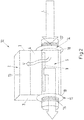
- the sand filling device 1 off Fig. 1 has the reservoir / "reservoir" 2 with the wall 3.
- the reservoir 2 is filled to a certain level with sand 4.
- the tube 5 Passed through the reservoir 2, the tube 5.
- the reservoir 2 is cut through, while the tube 5 is shown in its entirety.
- the wall 3 thus continues forward, in the direction of the viewer and encloses the tube 5 also at the two dashed lines drawn.
- the tube 5 is fitted by a press fit into the container 2 exactly in the openings 6, 7 in the wall 3.
- the tube 5 has the first portion A1, which is arranged outside of the storage container 2, the second portion A2, which is arranged in the interior of the storage container 2 and the third portion A3, which in turn is arranged outside of the storage container 2.
- compressed air L represented by an arrow
- the slot-shaped opening 9 trickles sand 4 in the second section A2 in the interior of the tube 5.
- the sand 4 is taken up by the compressed air L and there is formed a sand-air mixture SL, which is also shown with an arrow.
- the mixture SL leaves the tube 5 through the third section A3, through the outlet opening 10.
- the slot-shaped opening 9 is located on the top of the second portion A2 of the tube 5.
- the slot-shaped opening 9 is slightly offset towards the viewer in order to better represent them.
- the slot-shaped opening 5 is arranged exactly on the apex 11 of the upper side. But it can also, as shown here, be offset slightly to the side.
- the upper side of the tube is to be understood in particular to mean a region which is defined as follows: the upper half of the tube cross-sectional lateral surface lying above the horizontal plane of the tube cross-section. This means a range of - 90 ° to + 90 ° measured from the vertical. This is in Fig. 1 shown at the bottom right.
- the top is labeled OS there.
- Fig. 1 a pressure fit ("press-fit") of the tube 5 in the container 2.
- the interference fit should do without further sealing elements and is therefore to be regarded as "self-sealing”.
- Fig. 2 an alternative seal is made, namely with sealing elements 14, 15, which are applied to the tube 5, here in the form of sealing rings.
- Identical features as in Fig. 1 are in Fig. 2 denoted by identical reference numerals, wherein not all features are provided with reference numerals again.
- the sealing mechanism in Fig. 2 is as follows: A portion of the introduced air L penetrates through the slot-shaped opening 9 through the sand 4 in the void 13 of the reservoir and in the interstices in the sand bed 4. This part of the air is denoted by L '. As a result, in the interior of the reservoir 2, the pressure increases, and the reservoir 2 is stretched outwards, including the wall 3. This will pressed the wall 3 on both sides against the sealing elements 14, 15 and reaches a seal.
- the sealing elements 14, 15 are held in position by nuts, which are screwed onto threads 16, 17. Said nuts are not shown.
- the first sealing element 14 forms on the inside a first sealing surface 18, against which the wall 3 is pressed on the outside (right side).
- the second sealing element 15 forms on the side facing the reservoir 2 or the wall 3 a second sealing surface 19, against which the wall 3 is pressed on the left side. Even so, a "self-sealing" system is achieved only by pressurization and without further sealing measures such as gluing, welding, supplementary sealant materials, etc ..
- the first section A1 and the third section A3 could also be widened in relation to the second section A2, and the sealing elements 14, 15 could respectively abut against one flank of the expansion.
- the pipe 5 in the non-expanded area partially and again made available.
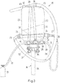
- Fig. 3 shows a concrete structure of a sand filling device 20 with the reservoir 21, which is filled with sand 22 just halfway.
- the reservoir 21 is made of plastic.
- the wall of the reservoir 21 is denoted by 23.
- the second section A2 of the tube 24 lies in the interior of the reservoir 21 and is shown in dashed lines.
- the section A2 has a slot-shaped opening 25. This extends substantially over the entire length of the section A2, but not quite to adjacent areas of the wall 23. This means that between the ends of the slot 25 and the wall 23, on the respective side of the slot end, a pitch without slot remains.
- the compressed air hose 26 is connected to a first end 27 via connecting means (hose clamp, connector).
- the compressed air hose 26 is connected at its other end 28 to the pressure control system 29.
- the pressure regulator 29 may alternatively be a simple check valve, so that a pressure control elsewhere can take place. Shown is the lever 30, for opening / closing the air flow. Schematically and not to scale a compressed air cylinder 31 is further shown, which is connected via the hose 32 to the control system / the valve 29.
- a hose 33 is connected via suitable fastening means (hose clamp). Through the tube 33 sand-air mixture is removed, which is formed in section A2.
- a filling opening 42 is shown on the top of the container, through which sand can be filled.
- the filling opening can be closed with a lid.
- FIG. 3 Also shows Fig. 3 also a pedestal 34 in a fragmentary view, on which the reservoir 21 is attached.
- the pedestal 34 has the column 35 which has a height adjustment device. Therein, the piston 36 is guided, on which an intermediate piece 37, the support plate 38 is attached. On the support plate 38 of the reservoir 21 is provided and secured with fastening strap 39
- FIG. 3 A special feature in Fig. 3 is the embodiment of the reservoir 21 made of plastic. This embodiment allows a particularly simple level control, since the level of sand fill is easily visible and thus the degree of filling of the sand filling device is particularly easy to determine.
- the reservoir 21 may be made of other materials such as e.g. Metal can be performed, with which the connection method "welding” or “sticking” offers.
- a separate viewing window (not shown in any figure) could be provided for level control.
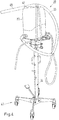
- Fig. 4 shows the same structure as Fig. 3 , In addition to Fig. 3 is still a blow-out unit 40 shown attached to the end of the hose 33. Furthermore, at the lower end of the pedestal 34 of the rollable foot 41 is shown.
- the sand filling device 20 is movable to any point of the rail vehicle to be filled, which is an additional comfort in the application of the invention.
Landscapes
- Engineering & Computer Science (AREA)
- Mechanical Engineering (AREA)
- Basic Packing Technique (AREA)
Abstract
Description
- Die vorliegende Erfindung betrifft eine Sandfüllungsvorrichtung, die zum Ausblasen von Sand oder zur Befüllung von Behältnissen verwendbar ist sowie ein Verfahren zum Ausblasen und/oder zum Befüllen eines Behältnisses mit Sand, wobei eine solche Vorrichtung eingesetzt wird.
- Schienenfahrzeuge, insbesondere Straßenbahnen, weisen häufig eine Sandungsanlage auf. Aus einer solchen Anlage ist im Bedarfsfall, beispielsweise bei einer Notbremsung, Sand aus dem Vorratsbehälter auf den Schienenweg zu streuen. Durch das Überfahren des Sandes wird der Reibbeiwert in der Rad-Schiene-Aufstandspaarung erhöht, d.h. die Reibung zwischen Rad und Schiene temporär erhöht, um das Fahrzeug in diesen speziellen Fällen - entweder automatisiert oder manuell getriggert - schneller zum Stillstand zu bringen. Auch beim Anfahren ist manchmal eine Erhöhung des Reibbeiwertes notwendig.
- Neben Sandungsanlagen für Schienenfahrzeuge sind aus dem Stand der Technik auch Sandungsanlagen für PKW bekannt.
US 3,797,867 zeigt eine solche Einrichtung mit einem Speicherbehälter für Sand und einer hindurchgeführten Rohrleitung mit Einlass-und Auslassöffnungen, wobei die Auslassöffnungen außerhalb der Speichereinrichtung angeordnet sind und die Einlassöffnungen seitlich an der Röhre angeordnet sind. Durch einen Ventilator wird in die Röhre Luft eingeblasen und ein Ansaugeffekt erzeugt, wodurch Sand aus dem Speicherbehälter durch die Öffnungen eingesaugt wird und durch die Röhre zu den Auslassöffnungen transportiert wird. Von dort aus wird der Sand auf Antriebsräder geleitet. - Je nach Kundenwünschen und Gegebenheiten werden verschiedene Sandtypen oder Sandmengen in der Sandungseinrichtung benötigt. Eine Sandungseinrichtung weist üblicherweise einen Sandvorratsbehälter auf, in dem der Sand gelagert ist. Bisher erfolgte die Befüllung des Sandvorratsbehälters mit Sand manuell unter Zuhilfenahme verschiedener Technologien
Aufgabe der vorliegenden Erfindung ist es, eine Sandfüllungsvorrichtung anzugeben, mit der ein üblicher Sandvorratsbehälter einer Sandungsanlage, insbesondere für Schienenfahrzeuge, leicht, schnell und sauber befüllbar ist. - Gelöst wird die Aufgabe durch eine Sandfüllungsvorrichtung nach Anspruch 1. Vorteilhafte Ausgestaltungen einer solchen Sandfüllungsvorrichtung sind in den Unteransprüchen angegeben. Ferner wird ein Verfahren zum Ausbringen von Sand angegeben.
- Angegeben wird eine Sandfüllungsvorrichtung, aufweisend
- einen Vorratsbehälter, der mit Sand oder Streugut befüllbar ist,
- eine Röhre, welche eine Wand des Vorratsbehälters zweifach durchstößt und durch den Vorratsbehälter hindurch geführt ist, sodass ein erster Abschnitt der Röhre außerhalb des Vorratsbehälters angeordnet ist, ein zweiter Abschnitt der Röhre im Inneren des Vorratsbehälters angeordnet ist, und ein dritter Abschnitt der Röhre außerhalb des Vorratsbehälters angeordnet ist,
- Da die Vorrichtung neben Sand auch andere Arten von Streugut ausbringen kann, ist zuvor und im Folgenden der Begriff "Sand" platzhaltend auch für andere Arten von Streugut wie sie im Betrieb des ÖPNV im Straßenverkehr vorkommen können, z.B. Granulat, feinkörniges Material aus anderen Grundwerkstoffen wie Abfallprodukte aus der Holzindustrie (Holzstaub, Holzspäne, ...), Kunststoffe, Streusalze und Mischungen daraus, etc. ...In diesem Sinn kann die erfindungsgemäße Vorrichtung auch als Streugutbefüllungsvorrichtung bezeichnet werden. Der Vorratsbehälter kann mit Sand, oder allgemein mit Streugut befüllt werden.
- Unter dem Begriff "Röhre" werden neben einem runden Querschnitt auch andere Arten von "Formrohren" verstanden, die z.B. ovale, rechteckige oder mehreckige Querschnitte aufweisen können.
- Dass die Röhre die Wand des Vorratsbehälters zweifach durchstößt bedeutet, dass die Röhre an einer ersten Stelle der Wand in den Vorratsbehälter eindringt und an einer zweiten Stelle der Wand aus dem Vorratsbehälter wieder austritt. An den jeweiligen Stellen durchstößt die Röhre die Wand. Die Wand kann eine umlaufende Seitenwand sein, beispielsweise wenn der Vorratsbehälter im Wesentlichen rund ausgeformt ist. Die Wand kann verschiedene Wandabschnitte aufweisen, die winklig zueinander sein können, beispielsweise wenn der Vorratsbehälter kastenförmig ausgebildet ist. Im Speziellen durchstößt die Röhre einen ersten Wandabschnitt und einen zweiten Wandabschnitt, welche einander gegenüberliegen.
- Der Begriff "Oberseite der Röhre" soll wie folgt verstanden werden: die Oberseite der Röhre ist jene Seite, die der Oberseite des Vorratsbehälters zugewandt ist. Anders ausgedrückt ist die Oberseite der Röhre jedenfalls eine dem Behälterboden abgewandte Seite. Es wird in diesem Bereich weiterhin ein Teilbereich verstanden, der oberhalb der horizontalen Ebene des Rohrquerschnittes liegt. Unter der Oberseite der Röhre wird erfindungsgemäß insbesondere ein Bereich verstanden, der wie folgt definiert ist: die oberhalb der horizontalen Ebene des Rohrquerschnittes liegende obere Hälfte der Rohrquerschnitt-Mantelfläche. Dies bedeutet einen Bereich von - 90° bis + 90° gemessen von der Senkrechten. Anders ausgedrückt: die obere Hälfte der Rohrquerschnitt-Mantelfläche (im zweiten Abschnitt des Rohres) charakterisiert die Oberseite und die maximale Arbeitslage der Sandfüllungsvorrichtung.
- Die Röhre ist in einer Ausführungsform in einem unteren Bereich des Vorratsbehälters durch den Vorratsbehälter hindurchgeführt. Auch hier kann auf die Arbeitslage der Sandfüllungsvorrichtung bzw. des Vorratsbehälters Bezug genommen werden.
- Auf der Oberseite der Röhre können mehrere Öffnungen vorhanden sein. Insbesondere sind eine oder mehrere schlitzförmige Öffnungen vorgesehen.
- In einer Ausführungsform erstreckt sich die schlitzförmige Öffnung in Längsrichtung der Röhre. Mehrere schlitzförmige Öffnungen können aneinander anschließen, mit dazwischen ausgebildeten Unterbrechungen.
- In einer bevorzugten Ausführungsform erstreckt sich die schlitzförmige Öffnung über den gesamten zweiten Abschnitt der Röhre oder im Wesentlichen über den zweiten Abschnitt. Auch hier können mehrere schlitzförmige Öffnungen in Längsrichtung der Röhre aneinander anschließen.
- Der Begriff "im Wesentlichen über den gesamten zweiten Abschnitt" bedeutet, dass die schlitzförmige Öffnung noch vor der Wand innerhalb des Vorratsbehälters endet.
- Die schlitzförmige Öffnung, insbesondere eine oder mehrere schlitzförmige Öffnungen, die sich im Wesentlichen über den gesamten zweiten Abschnitt erstreckt/erstrecken, hat/haben folgende technische Funktionen und Vorteile:
- Zum einen wird die Einleitung von Druckluft in den Vorratsbehälter ermöglicht, die den Sand im Vorratsbehälter durchströmen kann,
- Sand kann aus dem Vorratsbehälter durch Druckluft abtransportiert werden, nachdem er durch die schlitzförmige Öffnung in das Innere der Röhre gelangt ist, was durch Gravitation und/oder die Anwendung der Druckluft geschieht.
- Hauptarbeitsprinzip der erfindungsgemäßen Vorrichtung ist die Erzeugung eines gewissen Drucks innerhalb des gefüllten Vorratsbehälters und der Abtransport von Sand durch das Innere der Röhre, welcher durch die schlitzförmige Öffnung vom Vorratsbehälter in die Röhre gelangt. Durch die schlitzförmige Öffnung wird gleichermaßen das Eindringen von Luft in den Vorratsbehälter sowie das Einrieseln von Sand in die Röhre ermöglicht. In anderen Worten: Druckluft dringt durch die schlitzförmige Öffnung aus dem Inneren der Röhre in das Innere des Vorratsbehälters, gegebenenfalls durch eine Sandschicht, während durch die schlitzförmige Öffnung gleichzeitig auch das Einrieseln von Sand in die Röhre erfolgt. Der in das Innere der Röhre eingerieselte Sand wird weiterhin durch die Druckluft abtransportiert bzw. ausgeblasen. Die erfindungsgemäße Vorrichtung wird vorzugsweise so betrieben, dass ein permanenter und im Wesentlichen gleich bleibender Luftdruck in die Röhre eingebracht wird, sodass sich ein Gleichgewicht von einrieselndem und abzutransportierendem Sand und vorzugsweise auch ein gleichbleibender Druck innerhalb der Röhre einstellt. Bevorzugt stellt sich auch ein gleichbleibender Druck innerhalb des Vorratsbehälters ein.
- Vorstellbar ist auch eine pulsierende oder anderswertig frequenz-getaktete Druckaufbringung.
- Die Länge und Breite der schlitzförmigen Öffnung werden vorzugsweise so gewählt, dass das Innere der Röhre durch einrieselnden Sand nicht verstopft wird. Ziel ist es, den inneren Widerstand, der durch den Druckanstieg und gleichzeitige Kollision von Sandpartikeln während des Transports durch die schlitzförmige Öffnung sowie durch die Röhre entsteht, so weit wie möglich zu reduzieren. Anders ausgedrückt: der sich einstellende Druckanstieg innerhalb des Vorratsbehälters und der Röhre soll nicht wesentlich höher sein als der Druck, mit dem die Luft in das System eingeblasen wird.
- In einer Ausführungsform weist die Sandfüllungsvorrichtung eine Druckluftquelle auf, die an den ersten Abschnitt der Röhre der Sandfüllungsvorrichtung angeschlossen ist. Die Druckluftquelle kein ein Druckluftbehältnis oder ein Kompressor sein, insbesondere eine Druckluftflasche. Die Röhre weist eine Eingangsöffnung auf, die am Beginn des ersten Abschnitts liegt, und eine Ausgangsöffnung, die am Ende des dritten Abschnitts liegt. Erwähnte Sandausbringvorrichtung ist insbesondere an die erste Öffnung, die Eingangsöffnung, des ersten Abschnitts der Röhre angeschlossen. Der Anschluss kann beispielsweise über einen flexiblen Schlauch erfolgen.
- Von der Druckluftquelle wird Druckluft in das Innere der Röhre eingebracht. Bei der Druckluftquelle kann der Druck einstellbar, steuerbar oder regelbar sein. Ein bevorzugter Luftdruck, mit dem die erfindungsgemäße Vorrichtung betrieben wird, beträgt 1 - 2 bar, vorzugsweise 1,1 - 2 bar, mehr bevorzugt 1,2 - 2 bar, noch mehr bevorzugt 1,3 - 2 bar, oder 1,4 - 2 bar, oder 1,5 - 2 bar. Andere bevorzugte Druckbereiche sind 1,1 - 4 bar, mehr bevorzugt 1,2 - 4 bar, noch mehr bevorzugt 1,3 - 4 bar, oder 1,4 - 4 bar, oder 1,5 - 4 bar, oder 2 - 4 bar.
- An den dritten Abschnitt der Röhre der Sandfüllungsvorrichtung kann eine Ausblaseinheit angeschlossen sein, insbesondere an einer erwähnten Öffnung am Ende des dritten Abschnitts. Die Ausblaseinheit kann eine flexible Komponente aufweisen, wie einen Schlauch, und/oder eine starre Komponente, wie ein Rohr. Beispielsweise ist eine weiterführende Verschlauchung/Verrohrung zum Weitertransport des Sandes aus der Sandfüllungsvorrichtung in die Sandungsanlage eines Schienenfahrzeuges etc. angebracht. Durch die Ausblaseinheit kann ein Sand-Luft-Gemisch, das im Inneren der Röhre gebildet wird, ausgeblasen werden.
- In einer Ausführungsform der Sandfüllungsvorrichtung ist die Röhre beim Durchgang durch den Vorratsbehälter von Abschnitt 1 in Abschnitt 2 und von Abschnitt 2 in Abschnitt 3 in die Wand eingepasst.
- Vorzugsweise sind die Einpassungen als Presspassungen vorhanden. Durch die Presspassung wird eine Abdichtung zwischen der Rohraußenseite und der Wand des Vorratsbehälters bereitgestellt. Bei der Presspassung wird die Wand des Vorratsbehälters verformt und schmiegt sich an die Rohraußenseite an. Hierdurch wird eine Abdichtung zwischen Wand und Rohraußenseite bereitgestellt. Es handelt sich hier um eine sehr einfache und unkomplizierte Art der Abdichtung, wodurch die Bauteile nicht groß dimensioniert werden müssen und damit Gewicht eingespart werden kann. Eine solche Abdichtung ist insbesondere vorteilhaft verwendbar mit einem in die Röhre aufgebrachten Innendruck von 1 - 2 bar, oder einem anderen vorangehend genannten Druck. Bei der Presspassung kann auf jegliche weiteren Dichtungselemente, wie beispielsweise Dichtungsringe, verzichtet werden. Insofern ist die Presspassung eine selbstabdichtende Lösung. Zur Herstellung einer Presspassung kann die Wand des Vorratsbehälters mit Öffnungen versehen werden, insbesondere kreisförmigen Öffnungen, deren Durchmesser kleiner ist als der Außendurchmesser der Röhre. Die Röhre kann unter Kraftaufwendung durch die Öffnungen geführt werden, wodurch die Presspassung hergestellt wird. Die Presspassung wird auch als Übermaßpassung bezeichnet.
- In einer anderen Ausführungsform ist in dem ersten Abschnitt der Röhre (außerhalb des Vorratsbehälters) eine erste Dichtungsfläche vorgesehen, gegen welche die Wand pressbar ist, wenn das Innere des Vorratsbehälters mit Druck beaufschlagt wird. Die erste Dichtungsfläche ist vorzugsweise direkt benachbart zur Wand des Vorratsbehälters angeordnet.
- Alternativ oder zusätzlich kann an dem dritten Abschnitt der Röhre (außerhalb des Vorratsbehälters) eine zweite Dichtungsfläche vorgesehen sein, gegen welche die Wand pressbar ist, wenn das Innere des Vorratsbehälters mit Druck beaufschlagt wird. Die zweite Dichtungsfläche ist vorzugsweise direkt benachbart zur Wand des Vorratsbehälters angeordnet.
Diese Ausführungsform ist insbesondere vorteilhaft, wenn in das Innere der Röhre ein höherer Luftdruck eingebracht wird, insbesondere 1,5 - 4 bar, oder 2 - 4 bar, wodurch Sand noch schneller abtransportiert werden kann. Das Innere des Vorratsbehälters wird, wie bereits erläutert, mit Druck beaufschlagt, indem Druckluft aus der Röhre und gegebenenfalls durch Sand in den Vorratsbehälter einströmt. Hierdurch kann der Vorratsbehälter nach außen gedehnt werden, sodass sich die Wand jeweils an die erste bzw. zweite Dichtungsfläche anlegt. Auch hier handelt es sich um einen selbstabdichtenden Effekt. Es ist in diesem Fall nicht nötig, weitere Mittel auf der Innenseite der Vorratsbehälter-Wand vorzusehen (weitere Verschraubungen, etc...), um die Wand gegen die erste/zweite Dichtungsfläche zu pressen. Dies geschieht durch den eingebrachten Luftdruck. Spezielle Ausführungsformen, die diesem Prinzip gehorchen sind wie folgt: In einer Variante kann der Durchmesser der Röhre im ersten Abschnitt und im dritten Abschnitt gegenüber dem zweiten Abschnitt aufgeweitet sein. In diesem Falle ist zu Zwecken der Montage die Röhre vorzugsweise teilbar und entsprechend zusammenfügbar. An der Stelle der Aufweitung wird jeweils eine Dichtungsfläche gebildet, gegen welche die Wand pressbar ist. Zusätzlich kann jeweils ein Dichtungselement vor jene Stelle platziert werden, wo sich der Rohrdurchmesser aufweitet. - In einer weiteren Variante weisen der erste Abschnitt der Röhre und/oder der dritte Abschnitt der Röhre ein Außengewinde auf, vorzugsweise benachbart zu der Wand des Vorratsbehälters. Auf das Außengewinde kann eine Verstärkung aufgeschraubt werden, beispielsweise eine Mutter, an welcher eine Dichtungsfläche gebildet ist. Zusätzlich kann ein Dichtungselement, zum Beispiel ein Dichtungsring, vorgesehen sein.
- In vorangehend beschriebener Ausführungsform kann die Wand des Vorratsbehälters durch Verformung des Vorratsbehälters gegen die erste und/oder zweite Dichtungsfläche pressbar sein.
- Der Vorratsbehälter kann aus einem verformbaren Material bestehen, insbesondere einem elastisch und/oder plastisch verformbaren Material. Ein bevorzugtes Material für den Vorratsbehälter ist ein Kunststoff.
- In einer anderen Variante ist der Vorratsbehälter aus Metall. Die Röhre ist dann vorzugsweise mittels einer stoffschlüssigen Verbindung, insbesondere Schweißen oder Kleben, mit der Wand des Vorratsbehälters verbunden.
- In einer Variante wird die Röhre im Bereich des ersten Abschnittes und/oder des dritten Abschnittes mit dem Vorratsbehälter verschweißt. In diesem Falle müssen Vorratsbehälter und Rohr aus geeigneten Werkstoffpaarungen bestehen, welche verschweißbar sein müssen (Metall oder Kunststoff).
- In einer Ausführungsform weist die Sandfüllungsvorrichtung einen verfahrbaren oder verschiebbaren Untersatz auf, auf welchen der Vorratsbehälter aufgesetzt ist, oder an welchem der Vorratsbehälter befestigt ist. Durch einen solchen Untersatz wird eine Mobilität der Sandfüllungsvorrichtung ermöglicht, sodass die Vorrichtung an den Ort bewegt werden kann, wo sie gebraucht wird. Der Untersatz kann weiterhin höhenverstellbar sein, was gemeinsam mit der Verfahrbarkeit eine erfindungsgemäße Anwendungs-Verbesserung einer Sandfüllungsvorrichtung darstellt.
- In einer Ausführungsform weist die Sandfüllungsvorrichtung eine Befüllöffnung im Vorratsbehälter auf. Durch diese Befüllöffnung kann der Vorratsbehälter mit Sand befüllt werden. An die Befüllöffnung kann eine Zuleitung zur Einleitung von Sand in den Vorratsbehälter angeschlossen sein. Die Zuleitung kann mit einem Ventil oder einer Absperrvorrichtung versehen sein. Durch die Zuleitung kann Sand oder ein Sand-Luft-Gemisch in den Vorratsbehälter eingeleitet werden.
- In einem weiteren Aspekt betrifft die Erfindung ein Verfahren zum Ausbringen von Sand und/oder zum Befüllen eines Behältnisses mit Sand, wobei eine Sandfüllungsvorrichtung wie vorangehend beschrieben eingesetzt wird und das Verfahren die Schritte aufweist:
- Einrieseln von Sand aus dem Vorratsbehälter durch die schlitzförmige Öffnung in den zweiten Abschnitt der Röhre infolge Schwerkraft in Verbindung mit Druckbeaufschlagung;
- Einleiten von Druckluft in den ersten Abschnitt der Röhre, sodass die Druckluft von dem ersten Abschnitt in den zweiten Abschnitt geströmt wird, sich dort mit eingerieseltem Sand vermischt und ein Sand-Luft-Gemische gebildet wird, welches durch den dritten Abschnitt transportiert wird,
- Ausblasen des Sand-Luft-Gemisches aus dem dritten Abschnitt und
- optional Einleiten des Sand-Luft-Gemisches in ein zu befüllendes Behältnis.
- Beim Einleiten von Druckluft in den ersten Abschnitt der Röhre kann die Luft vom ersten Abschnitt in den zweiten Abschnitt strömen und dort einerseits in den Vorratsbehälter gelangen und sich andererseits mit eingerieseltem Sand vermischen. Beim Vermischen mit dem eingerieselten Sand wird ein Sand-Luft-Gemisch gebildet, welches durch den dritten Abschnitt transportiert wird.
- Eine Weiterleitung des Sand-Luft-Gemisches kann in eine zu befüllende Sandungsvorrichtung erfolgen
Die Druckbeaufschlagung kann durch Druckluft erfolgen, die in den Vorratsbehälter eingeleitet wird. Wie oben bereits erwähnt, kann Druckluft, die in die Röhre eingeleitet wird, den Sand im Vorratsbehälter durchströmen und einen Druck im Inneren des Vorratsbehälters aufbauen. - In dem erfindungsgemäßen Verfahren können in beliebiger Kombination die Merkmale eingesetzt werden, die zuvor anhand einer erfindungsgemäßen Sandfüllungsvorrichtung beschrieben wurden. Ebenfalls können in dem Verfahren Merkmale vorhanden sein, die anhand einer erfindungsgemäßen Vorrichtung verfahrensmäßig formuliert sind. Umgekehrt können gegenständliche Merkmale der Vorrichtung durch Funktionalitäten gekennzeichnet sein, die anhand eines erfindungsgemäßen Verfahrens beschrieben sind.
- Das gemäß dem Verfahren befüllbare Behältnis ist insbesondere ein Sandbehälter einer Sandungsanlage für ein Schienenfahrzeug. Das Ausbringen von Sand aus der Sandfüllungsvorrichtung kann an einer beliebigen Stelle erfolgen, wo Sandfüllung benötigt wird, insbesondere wenn die Vorrichtung verfahrbar ist
- Nachfolgend wird die Erfindung anhand von Ausführungsbeispielen beschrieben. Es zeigen.
- Fig. 1
- eine Sandfüllungsvorrichtung in schematischer Ansicht
- Fig. 2
- eine alternative Ausführungsform der Sandfüllungsvorrichtung in schematischer Ansicht
- Fig. 3
- einen konkreten Aufbau einer Sandfüllungsvorrichtung in einer ersten Ansicht
- Fig. 4
- die Sandfüllungsvorrichtung nach
Fig. 3 mit weiteren Merkmalen - Die Sandfüllungsvorrichtung 1 aus
Fig. 1 weist den Vorratsbehälter/"Reservoir" 2 mit der Wand 3 auf. Der Vorratsbehälter 2 ist bis zu einer bestimmten Füllhöhe mit Sand 4 befüllt. - Durch den Vorratsbehälter 2 hindurchgeführt ist die Röhre 5. In der Ansicht der
Fig. 1 ist der Vorratsbehälter 2 durchschnitten, während die Röhre 5 in Gänze gezeigt ist. Die Wand 3 setzt sich also nach vorn, in Blickrichtung des Betrachters fort und umschließt die Röhre 5 auch an den beiden eingezeichneten gestrichelten Linien. Die Röhre 5 ist durch eine Presspassung in den Behälter 2 genau in den Öffnungen 6, 7 in die Wand 3 eingepasst. - Die Röhre 5 weist den ersten Abschnitt A1 auf, der außerhalb des Vorratsbehälters 2 angeordnet ist, den zweiten Abschnitt A2, der im Inneren des Vorratsbehälters 2 angeordnet ist und den dritten Abschnitt A3, der wiederum außerhalb des Vorratsbehälters 2 angeordnet ist. Durch die Eingangsöffnung 8 wird Druckluft L, dargestellt durch einen Pfeil, in die Röhre 5 eingeleitet. Durch die schlitzförmige Öffnung 9 rieselt Sand 4 im zweiten Abschnitt A2 in das Innere der Röhre 5. Dort wird der Sand 4 von der Druckluft L aufgenommen und es wird ein Sand-Luft-Gemisch SL gebildet, das ebenfalls mit einem Pfeil dargestellt ist. Das Gemisch SL verlässt die Röhre 5 durch den dritten Abschnitt A3, durch die Ausgangsöffnung 10.
- Die schlitzförmige Öffnung 9 befindet sich auf der Oberseite des zweiten Abschnitts A2 der Röhre 5. In der Ansicht der
Fig. 1 ist die schlitzförmige Öffnung 9 leicht zum Betrachter hin versetzt, um sie besser darstellen zu können. Vorzugsweise ist die schlitzförmige Öffnung 5 genau auf dem Scheitel 11 der Oberseite angeordnet. Sie kann aber auch, wie hier gezeigt, etwas zur Seite hin versetzt sein. Unter der Oberseite der Röhre wird erfindungsgemäß insbesondere ein Bereich verstanden, der wie folgt definiert ist: die oberhalb der horizontalen Ebene des Rohrquerschnittes liegende obere Hälfte der Rohrquerschnitt-Mantelfläche. Dies bedeutet einen Bereich von - 90° bis + 90° gemessen von der Senkrechten. Dies ist inFig. 1 rechts unten dargestellt. Die Oberseite ist dort mit OS bezeichnet. - Wie erwähnt, zeigt
Fig. 1 eine Presspassung ("press-fit") der Röhre 5 in den Behälter 2. Bei Druckbereichen bis 2 bar sollte die Presspassung ohne weitere Dichtungselemente auskommen und ist somit als "selbstabdichtend" anzusehen.
InFig. 2 ist eine alternative Abdichtung hergestellt, nämlich mit Dichtungselementen 14, 15, die auf die Röhre 5 aufgebracht sind, hier in Form von Dichtungsringen. Identische Merkmale wie inFig. 1 sind inFig. 2 mit identischen Bezugszeichen bezeichnet, wobei nicht alle Merkmale erneut mit Bezugszeichen versehen sind. - Der Dichtungsmechanismus in
Fig. 2 ist wie folgt: Ein Teil der eingeleiteten Luft L dringt durch die schlitzförmige Öffnung 9 durch den Sand 4 in den Leerraum 13 des Vorratsbehälters ein und in die Zwischenräume in der Sandschüttung 4. Dieser Teil der Luft ist mit L' bezeichnet. Hierdurch steigt im Inneren des Vorratsbehälters 2 der Druck an, und der Vorratsbehälter 2 wird nach außen gedehnt, also auch die Wand 3. Dadurch wird die Wand 3 auf beiden Seiten gegen die Dichtungselemente 14, 15 gepresst und eine Abdichtung erreicht. Die Dichtungselemente 14, 15 werden durch Muttern in ihrer Position gehalten, welche auf Gewinde 16, 17 aufgeschraubt sind. Besagte Muttern sind nicht dargestellt. Das erste Dichtungselement 14 bildet innenseitlich eine erste Dichtungsfläche 18, gegen welche die Wand 3 auf der Außenseite (rechte Seite) gepresst wird. In gleicher Weise bildet das zweite Dichtungselement 15 auf der dem Vorratsbehälter 2 bzw. der Wand 3 zugewandten Seite eine zweite Dichtungsfläche 19, gegen welche die Wand 3 auf der linken Seite gepresst wird. Auch damit wird nur durch Druckbeaufschlagung und ohne weitere Abdichtungsmaßnahmen wie z.B. Kleben, Schweißen, ergänzende Dichtmasse-Werkstoffe, etc... ein "selbstabdichtendes" System erreicht. - Alternativ zu einer Fixierung mit (nicht gezeigten) Muttern könnten der erste Abschnitt A1 und der dritte Abschnitt A3 auch gegenüber dem zweiten Abschnitt A2 aufgeweitet sein und die Dichtungselemente 14, 15 könnten jeweils an einer Flanke der Aufweitung anliegen. In diesem Falle ist zu Montagezwecken das Rohr 5 im nicht-aufgeweiteten Bereich teil- und wieder fügbar ausgeführt.
-
Fig. 3 zeigt einen konkreten Aufbau einer Sandfüllungsvorrichtung 20 mit dem Vorratsbehälter 21, der mit Sand 22 knapp bis zur Hälfte befüllt ist. Der Vorratsbehälter 21 ist aus Kunststoff. Die Wand des Vorratsbehälters 21 ist mit 23 bezeichnet. - Der zweite Abschnitt A2 der Röhre 24 liegt im Inneren des Vorratsbehälters 21 und ist gestrichelt gezeichnet. Wie in der Ausführungsform aus
Fig. 1 undFig. 2 weist der Abschnitt A2 eine schlitzförmige Öffnung 25 auf. Diese erstreckt sich im Wesentlichen über die gesamte Länge des Abschnittes A2, aber nicht ganz bis zu benachbarten Bereichen der Wand 23. Das bedeutet, dass zwischen den Enden des Schlitzes 25 und der Wand 23, auf der jeweiligen Seite des Schlitzendes, ein Rohrabstand ohne Schlitz verbleibt. - An den Eingang der Röhre 24 am Abschnitt A1, d.h. an die Öffnung am Beginn des Abschnitts A1 (in
Fig. 1 mit dem Bezugszeichen 8 bezeichnet), ist der Druckluftschlauch 26 mit einem ersten Ende 27 über Verbindungsmittel (Schlauchschelle, Verbindungsstück) angeschlossen. Der Druckluftschlauch 26 ist mit seinem anderen Ende 28 an die Druckregelanlage 29 angeschlossen. Die Druckregelanlage 29 kann alternativ ein einfaches Sperrventil sein, sodass eine Druckregelung an anderer Stelle stattfinden kann. Gezeigt ist der Hebel 30, zum Öffnen/Verschließen des Luftdurchflusses. Schematisch und nicht maßstabsgetreu ist ferner eine Druckluftflasche 31 gezeigt, die über den Schlauch 32 an die Regelanlage/das Ventil 29 angeschlossen ist. - An das Ende des dritten Abschnitts A3, jene Öffnung, die in
Fig. 1 mit 10 bezeichnet ist, ist eine Schlauchleitung 33 über geeignete Befestigungsmittel (Schlauchschelle) angeschlossen. Durch den Schlauch 33 wird Sand-Luft-Gemisch abtransportiert, das im Abschnitt A2 gebildet wird. - In
Fig. 3 ist eine Befüllöffnung 42 auf der Oberseite des Behälters gezeigt, durch welche Sand eingefüllt werden kann. Die Befüllöffnung kann mit einem Deckel verschlossen werden. - Schließlich zeigt
Fig. 3 auch einen Untersatz 34 in ausschnittweiser Darstellung, auf dem der Vorratsbehälter 21 befestigt ist. Der Untersatz 34 weist die Säule 35 auf, die über eine Höhenverstellvorrichtung verfügt. Darin ist der Kolben 36 geführt, an dem über ein Zwischenstück 37 die Auflageplatte 38 befestigt ist. Auf die Auflageplatte 38 ist der Vorratsbehälter 21 gestellt und mit Befestigungsriemen 39 befestigt - Eine Besonderheit in
Fig. 3 ist die Ausgestaltung des Vorratsbehälters 21 aus Kunststoff. Diese Ausgestaltung erlaubt eine besonders einfache Füllstandskontrolle, da das Niveau der Sandschüttung leicht ersichtlich ist und damit der Füllgrad der Sandfüllungs-vorrichtung besonders einfach festzustellen ist. - Alternativ kann der Vorratsbehälter 21 aus anderen Werkstoffen wie z.B. Metall ausgeführt werden, womit sich die Verbindungsmethode "schweißen" oder "kleben" anbietet. In diesem Falle könnte ein eigenes Sichtfenster (in keiner Fig. dargestellt) zur Füllstandskontrolle vorgesehen sein.
-
Fig. 4 zeigt den gleichen Aufbau wieFig. 3 . Zusätzlich zuFig. 3 ist noch eine Ausblaseinheit 40 abgebildet, die am Ende des Schlauches 33 befestigt ist. Weiterhin ist am unteren Ende des Untersatzes 34 der rollbare Fuß 41 gezeigt. Hiermit ist die Sandfüllungsvorrichtung 20 an eine beliebige Stelle des zu befüllenden Schienenfahrzeuges verfahrbar, was einen zusätzlichen Komfort bei der Anwendung der Erfindung darstellt. -
- 1
- Sandfüllungsvorrichtung
- 2
- Vorratsbehälter
- 3
- Wand
- 4
- Sand
- 5
- Röhre
- 6
- Öffnung
- 7
- Öffnung
- 8
- Eingangsöffnung
- 9
- schlitzförmige Öffnung
- 10
- Ausgangsöffnung
- 11
- Scheitel
- 13
- Leerraum
- 14
- Dichtungselement
- 15
- Dichtungselement
- 16
- Gewinde
- 17
- Gewinde
- 18
- Dichtungsfläche
- 19
- Dichtungsfläche
- 20
- Sandfüllungsvorrichtung
- 21
- Vorratsbehälter
- 22
- Sand
- 23
- Wand
- 24
- Röhre
- 25
- schlitzförmige Öffnung
- 26
- Druckluftschlauch
- 27
- Ende
- 28
- Ende
- 29
- Druckregelanlage
- 30
- Hebel
- 31
- Druckluftflasche
- 32
- Schlauch
- 33
- Schlauch
- 34
- Untersatz
- 35
- Säule
- 36
- Kolben
- 37
- Zwischenstück
- 38
- Auflageplatte
- 39
- Befestigungsriemen
- 40
- Ausblaseinheit
- 41
- Fuß
- 42
- Befüllöffnung
- A1
- erster Abschnitt
- A2
- zweiter Abschnitt
- A3
- dritter Abschnitt
- L
- Druckluft
- L'
- Luft
- SL
- Sand-Luft-Gemisch
- OS
- Oberseite
Claims (15)
- Sandfüllungsvorrichtung (1; 20), aufweisend- einen Vorratsbehälter (2; 21), der mit Sand (4; 22) oder Streugut befüllbar ist,- eine Röhre (5; 24), welche eine Wand (3; 23) des Vorratsbehälters zweifach durchstößt und durch den Vorratsbehälter hindurch geführt ist, sodass ein erster Abschnitt (A1) der Röhre außerhalb des Vorratsbehälters (2; 21) angeordnet ist, ein zweiter Abschnitt (A2) der Röhre im Inneren des Vorratsbehälters und ein dritter Abschnitt (A3) der Röhre außerhalb des Vorratsbehälters (2; 21) angeordnet ist,dadurch gekennzeichnet, dass
die Röhre (5; 24) auf einer Oberseite (OS) des zweiten Abschnitts (A2) zumindest eine schlitzförmige Öffnung (9; 25) aufweist, durch welche der Sand (4; 22) aus dem Vorratsbehälter in das Innere der Röhre einrieselbar ist. - Sandfüllungsvorrichtung (1; 20) nach Anspruch 1, wobei sich die zumindest eine schlitzförmige Öffnung (9; 25) in Längsrichtung der Röhre (5; 24) erstreckt.
- Sandfüllungsvorrichtung (1; 20) nach einem der vorangehenden Ansprüche, wobei sich die zumindest eine schlitzförmige Öffnung (9; 25) im Wesentlichen über den gesamten zweiten Abschnitt (A2) erstreckt.
- Sandfüllungsvorrichtung nach einem der vorangehenden Ansprüche, aufweisend eine Druckluftquelle (31), die an den ersten Abschnitt (A1) der Röhre (5; 24) angeschlossen ist.
- Sandfüllungsvorrichtung nach einem der vorangehenden Ansprüche, aufweisend eine Ausblaseinheit (40), die an den dritten Abschnitt (A3) der Röhre (5; 24) angeschlossen ist.
- Sandfüllungsvorrichtung nach einem der vorangehenden Ansprüche, wobei die Röhre (5; 24) durch eine Presspassung in die Wand (3; 23) eingepasst ist.
- Sandfüllungsvorrichtung nach einem der Ansprüche 1-6, wobei an dem ersten Abschnitt (A1) der Röhre (5; 24) eine erste Dichtungsfläche (18) vorgesehen ist, gegen welche die Wand (3; 23) pressbar ist, wenn das Innere des Vorratsbehälters mit Druck beaufschlagt wird, und/oder an dem dritten Abschnitt (A3) der Röhre eine zweite Dichtungsfläche (19) vorgesehen ist, gegen welche die Wand (3; 23) pressbar ist, wenn der Innenraum (13) des Vorratsbehälters mit Druck beaufschlagt wird.
- Sandfüllungsvorrichtung nach Anspruch 7, wobei die Wand (3; 23) durch Verformung des Vorratsbehälters gegen die erste Dichtungsfläche (18) und/oder zweite Dichtungsfläche (19) pressbar ist.
- Sandfüllungsvorrichtung nach einem der vorangehenden Ansprüche, wobei der Werkstoff des Vorratsbehälters (2; 21) aus Kunststoff ist.
- Sandfüllungsvorrichtung nach einem der Ansprüche 1-8, wobei der Werkstoff des Vorratsbehälters (2; 21) aus Metall ist, wobei vorzugsweise die Röhre (5; 24) mittels einer stoffschlüssigen Verbindung, wie Schweißen oder Kleben, mit der Wand (3; 23) verbunden ist.
- Sandfüllungsvorrichtung nach einem der vorangehenden Ansprüche, aufweisend einen verschiebbaren oder verfahrbaren Untersatz (34), auf welchen der Vorratsbehälter aufgesetzt ist oder am welchem der Vorratsbehälter (2; 21) befestigt ist.
- Sandfüllungsvorrichtung nach Anspruch 11, wobei der Untersatz (34) höhenverstellbar ist.
- Sandfüllungsvorrichtung nach einem der vorangehenden Ansprüche, aufweisend eine Befüllöffnung (42) in dem Vorratsbehälter (21), durch die der Vorratsbehälter mit dem Sand befüllbar ist.
- Sandfüllungsvorrichtung nach Anspruch 13, aufweisend eine Zuleitung zur Einleitung des Sandes in den Vorratsbehälter (21), welche an die Befüllöffnung (42) angeschlossen ist.
- Verfahren zum Ausbringen von Sand und/oder zum Befüllen eines Behältnisses mit Sand, wobei eine Sandfüllungsvorrichtung nach einem der Ansprüche 1-14 eingesetzt wird und das Verfahren die Schritte aufweist:- Einrieseln von Sand (4; 22) aus dem Vorratsbehälter (2; 21) durch die schlitzförmige Öffnung (9; 25) in den zweiten Abschnitt (A2) der Röhre (5; 24) infolge Schwerkraft in Verbindung mit Druckbeaufschlagung,- Einleiten von Druckluft (L) in den ersten Abschnitt (A1) der Röhre (5; 24), sodass die Druckluft (L) von dem ersten Abschnitt (A1) in den zweiten Abschnitt (A2) geströmt wird, sich dort mit dem eingerieselten Sand vermischt und ein Sand-Luft-Gemisch (SL) gebildet wird, welches durch den dritten Abschnitt (A3) transportiert wird,- Ausblasen des Sand-Luft-Gemisches (SL) aus dem dritten Abschnitt (A3)- optional Einleiten des Sand-Luft-Gemisches (SL) in ein zu befüllendes Behältnis.
Priority Applications (1)
| Application Number | Priority Date | Filing Date | Title |
|---|---|---|---|
| PL17167973T PL3241717T3 (pl) | 2016-05-04 | 2017-04-25 | Urządzenie do napełniania piaskiem |
Applications Claiming Priority (1)
| Application Number | Priority Date | Filing Date | Title |
|---|---|---|---|
| DE102016207719.8A DE102016207719A1 (de) | 2016-05-04 | 2016-05-04 | Sandfüllungsvorrichtung |
Publications (2)
| Publication Number | Publication Date |
|---|---|
| EP3241717A1 true EP3241717A1 (de) | 2017-11-08 |
| EP3241717B1 EP3241717B1 (de) | 2020-07-29 |
Family
ID=58632826
Family Applications (1)
| Application Number | Title | Priority Date | Filing Date |
|---|---|---|---|
| EP17167973.1A Active EP3241717B1 (de) | 2016-05-04 | 2017-04-25 | Sandfüllungsvorrichtung |
Country Status (4)
| Country | Link |
|---|---|
| EP (1) | EP3241717B1 (de) |
| DE (1) | DE102016207719A1 (de) |
| ES (1) | ES2818537T3 (de) |
| PL (1) | PL3241717T3 (de) |
Citations (5)
| Publication number | Priority date | Publication date | Assignee | Title |
|---|---|---|---|---|
| AT213774B (de) * | 1959-10-14 | 1961-02-27 | Adolf Kafka | Fördereinrichtung, insbesondere für landwirtschaftliche Produkte |
| US3797867A (en) | 1972-06-07 | 1974-03-19 | J Hartl | Pneumatic vehicle sanding apparatus |
| US4098412A (en) * | 1976-10-12 | 1978-07-04 | Sun Shipbuilding & Dry Dock Company | Pneumatic offloading system for tanker |
| EP0747305A1 (de) * | 1995-06-07 | 1996-12-11 | Fosfoquim S.A. | Gerät und Verfahren zum Zuführen von teilchenförmigem Material |
| EP1182109A1 (de) * | 2000-03-17 | 2002-02-27 | Railway Technical Research Institute | Einspritzvorrichtung für schlupfverhindernde partikel |
-
2016
- 2016-05-04 DE DE102016207719.8A patent/DE102016207719A1/de not_active Withdrawn
-
2017
- 2017-04-25 ES ES17167973T patent/ES2818537T3/es active Active
- 2017-04-25 PL PL17167973T patent/PL3241717T3/pl unknown
- 2017-04-25 EP EP17167973.1A patent/EP3241717B1/de active Active
Patent Citations (5)
| Publication number | Priority date | Publication date | Assignee | Title |
|---|---|---|---|---|
| AT213774B (de) * | 1959-10-14 | 1961-02-27 | Adolf Kafka | Fördereinrichtung, insbesondere für landwirtschaftliche Produkte |
| US3797867A (en) | 1972-06-07 | 1974-03-19 | J Hartl | Pneumatic vehicle sanding apparatus |
| US4098412A (en) * | 1976-10-12 | 1978-07-04 | Sun Shipbuilding & Dry Dock Company | Pneumatic offloading system for tanker |
| EP0747305A1 (de) * | 1995-06-07 | 1996-12-11 | Fosfoquim S.A. | Gerät und Verfahren zum Zuführen von teilchenförmigem Material |
| EP1182109A1 (de) * | 2000-03-17 | 2002-02-27 | Railway Technical Research Institute | Einspritzvorrichtung für schlupfverhindernde partikel |
Also Published As
| Publication number | Publication date |
|---|---|
| ES2818537T3 (es) | 2021-04-13 |
| PL3241717T3 (pl) | 2020-12-14 |
| EP3241717B1 (de) | 2020-07-29 |
| DE102016207719A1 (de) | 2017-11-09 |
Similar Documents
| Publication | Publication Date | Title |
|---|---|---|
| DE202007003526U1 (de) | In der Breite verstellbare Trennwand für Automobile | |
| DE4031236A1 (de) | Vorrichtung zum formen eines profilstrangs durch extrudieren unmittelbar auf dem rand einer glasscheibe | |
| DE69422240T2 (de) | Extrusion von Verbundmaterial mit Breiteneinstellungsmöglichkeit | |
| AT506538A1 (de) | Sandungssystem für schienenfahrzeuge | |
| EP2331410B1 (de) | Verfahren und vorrichtung zum füllen | |
| WO2015055723A1 (de) | Dosiereinrichtung für granulat | |
| CH701223A1 (de) | Schlauchaufrollvorrichtung. | |
| EP2311653B1 (de) | Sandaustragungseinrichtung für ein Schienenfahrzeug | |
| EP3241717B1 (de) | Sandfüllungsvorrichtung | |
| DE10339814B4 (de) | Abstützeinrichtung | |
| DE102006014719A1 (de) | Trägerprofil und Befestigungsanordnung eines Sitzuntergestells an einer Bodenanlage eines Omnibusses | |
| CH645838A5 (de) | Vorrichtung zur herstellung von verbundprofilen, insbesondere fuer fensterrahmen, tuerrahmen und fassaden. | |
| WO2022194770A1 (de) | Profilkühlvorrichtung und kühlstrang für eine profilkühlvorrichtung | |
| DE10325346B4 (de) | Vorrichtung zur Verringerung des Luftwiderstandes | |
| DE202004010339U1 (de) | Druckluftschaum-Feuerlöschanlage für einen Tunnel | |
| DE10350468B4 (de) | Vorrichtung und Verfahren zum Befüllen eines Vorratsbehälters mit Bremssand oder dergleichen Schüttgut | |
| EP0065061A2 (de) | Hydraulische Kolbengleisbremse zum Abbremsen von Eisenbahnwagen | |
| EP3180223B1 (de) | Schienenfahrzeug mit klimaanlage | |
| DE102014202467A1 (de) | Vorrichtung zur Herstellung einer Gummimischung | |
| EP2332814A2 (de) | Zusammenlegbares bzw. zusammenklappbares Fahrrad | |
| DE69614774T2 (de) | Vorrichtung zur Verteilung von pastösen Produkten, wie Putz oder Mörtel, insbesondere für Bauwerke | |
| DE20217390U1 (de) | Druckluftbetriebene Sandstreuvorrichtung | |
| DE102018202012A1 (de) | Schüttguttrichter und Schüttgut-Beschickungsanlage mit einem Schüttguttrichter | |
| DE29611292U1 (de) | Filtereinrichtung für Strangpreß- und Spritzgießmaschinen | |
| DE3801700A1 (de) | Doppelwandige bodenplatte eines beluefteten containers |
Legal Events
| Date | Code | Title | Description |
|---|---|---|---|
| PUAI | Public reference made under article 153(3) epc to a published international application that has entered the european phase |
Free format text: ORIGINAL CODE: 0009012 |
|
| STAA | Information on the status of an ep patent application or granted ep patent |
Free format text: STATUS: THE APPLICATION HAS BEEN PUBLISHED |
|
| AK | Designated contracting states |
Kind code of ref document: A1 Designated state(s): AL AT BE BG CH CY CZ DE DK EE ES FI FR GB GR HR HU IE IS IT LI LT LU LV MC MK MT NL NO PL PT RO RS SE SI SK SM TR |
|
| AX | Request for extension of the european patent |
Extension state: BA ME |
|
| STAA | Information on the status of an ep patent application or granted ep patent |
Free format text: STATUS: REQUEST FOR EXAMINATION WAS MADE |
|
| 17P | Request for examination filed |
Effective date: 20180504 |
|
| RBV | Designated contracting states (corrected) |
Designated state(s): AL AT BE BG CH CY CZ DE DK EE ES FI FR GB GR HR HU IE IS IT LI LT LU LV MC MK MT NL NO PL PT RO RS SE SI SK SM TR |
|
| STAA | Information on the status of an ep patent application or granted ep patent |
Free format text: STATUS: EXAMINATION IS IN PROGRESS |
|
| 17Q | First examination report despatched |
Effective date: 20190506 |
|
| GRAP | Despatch of communication of intention to grant a patent |
Free format text: ORIGINAL CODE: EPIDOSNIGR1 |
|
| STAA | Information on the status of an ep patent application or granted ep patent |
Free format text: STATUS: GRANT OF PATENT IS INTENDED |
|
| INTG | Intention to grant announced |
Effective date: 20200214 |
|
| GRAS | Grant fee paid |
Free format text: ORIGINAL CODE: EPIDOSNIGR3 |
|
| GRAA | (expected) grant |
Free format text: ORIGINAL CODE: 0009210 |
|
| STAA | Information on the status of an ep patent application or granted ep patent |
Free format text: STATUS: THE PATENT HAS BEEN GRANTED |
|
| AK | Designated contracting states |
Kind code of ref document: B1 Designated state(s): AL AT BE BG CH CY CZ DE DK EE ES FI FR GB GR HR HU IE IS IT LI LT LU LV MC MK MT NL NO PL PT RO RS SE SI SK SM TR |
|
| RAP1 | Party data changed (applicant data changed or rights of an application transferred) |
Owner name: BOMBARDIER TRANSPORTATION GMBH |
|
| REG | Reference to a national code |
Ref country code: CH Ref legal event code: EP |
|
| REG | Reference to a national code |
Ref country code: AT Ref legal event code: REF Ref document number: 1295448 Country of ref document: AT Kind code of ref document: T Effective date: 20200815 |
|
| REG | Reference to a national code |
Ref country code: IE Ref legal event code: FG4D Free format text: LANGUAGE OF EP DOCUMENT: GERMAN |
|
| REG | Reference to a national code |
Ref country code: DE Ref legal event code: R096 Ref document number: 502017006383 Country of ref document: DE |
|
| REG | Reference to a national code |
Ref country code: CH Ref legal event code: NV Representative=s name: PATENTANWALT DIPL.-ING. (UNI.) WOLFGANG HEISEL, CH |
|
| REG | Reference to a national code |
Ref country code: LT Ref legal event code: MG4D |
|
| REG | Reference to a national code |
Ref country code: NL Ref legal event code: MP Effective date: 20200729 |
|
| PG25 | Lapsed in a contracting state [announced via postgrant information from national office to epo] |
Ref country code: FI Free format text: LAPSE BECAUSE OF FAILURE TO SUBMIT A TRANSLATION OF THE DESCRIPTION OR TO PAY THE FEE WITHIN THE PRESCRIBED TIME-LIMIT Effective date: 20200729 Ref country code: GR Free format text: LAPSE BECAUSE OF FAILURE TO SUBMIT A TRANSLATION OF THE DESCRIPTION OR TO PAY THE FEE WITHIN THE PRESCRIBED TIME-LIMIT Effective date: 20201030 Ref country code: LT Free format text: LAPSE BECAUSE OF FAILURE TO SUBMIT A TRANSLATION OF THE DESCRIPTION OR TO PAY THE FEE WITHIN THE PRESCRIBED TIME-LIMIT Effective date: 20200729 Ref country code: BG Free format text: LAPSE BECAUSE OF FAILURE TO SUBMIT A TRANSLATION OF THE DESCRIPTION OR TO PAY THE FEE WITHIN THE PRESCRIBED TIME-LIMIT Effective date: 20201029 Ref country code: NO Free format text: LAPSE BECAUSE OF FAILURE TO SUBMIT A TRANSLATION OF THE DESCRIPTION OR TO PAY THE FEE WITHIN THE PRESCRIBED TIME-LIMIT Effective date: 20201029 Ref country code: HR Free format text: LAPSE BECAUSE OF FAILURE TO SUBMIT A TRANSLATION OF THE DESCRIPTION OR TO PAY THE FEE WITHIN THE PRESCRIBED TIME-LIMIT Effective date: 20200729 Ref country code: PT Free format text: LAPSE BECAUSE OF FAILURE TO SUBMIT A TRANSLATION OF THE DESCRIPTION OR TO PAY THE FEE WITHIN THE PRESCRIBED TIME-LIMIT Effective date: 20201130 Ref country code: SE Free format text: LAPSE BECAUSE OF FAILURE TO SUBMIT A TRANSLATION OF THE DESCRIPTION OR TO PAY THE FEE WITHIN THE PRESCRIBED TIME-LIMIT Effective date: 20200729 |
|
| PG25 | Lapsed in a contracting state [announced via postgrant information from national office to epo] |
Ref country code: LV Free format text: LAPSE BECAUSE OF FAILURE TO SUBMIT A TRANSLATION OF THE DESCRIPTION OR TO PAY THE FEE WITHIN THE PRESCRIBED TIME-LIMIT Effective date: 20200729 Ref country code: RS Free format text: LAPSE BECAUSE OF FAILURE TO SUBMIT A TRANSLATION OF THE DESCRIPTION OR TO PAY THE FEE WITHIN THE PRESCRIBED TIME-LIMIT Effective date: 20200729 Ref country code: IS Free format text: LAPSE BECAUSE OF FAILURE TO SUBMIT A TRANSLATION OF THE DESCRIPTION OR TO PAY THE FEE WITHIN THE PRESCRIBED TIME-LIMIT Effective date: 20201129 |
|
| PG25 | Lapsed in a contracting state [announced via postgrant information from national office to epo] |
Ref country code: NL Free format text: LAPSE BECAUSE OF FAILURE TO SUBMIT A TRANSLATION OF THE DESCRIPTION OR TO PAY THE FEE WITHIN THE PRESCRIBED TIME-LIMIT Effective date: 20200729 |
|
| REG | Reference to a national code |
Ref country code: ES Ref legal event code: FG2A Ref document number: 2818537 Country of ref document: ES Kind code of ref document: T3 Effective date: 20210413 |
|
| PG25 | Lapsed in a contracting state [announced via postgrant information from national office to epo] |
Ref country code: RO Free format text: LAPSE BECAUSE OF FAILURE TO SUBMIT A TRANSLATION OF THE DESCRIPTION OR TO PAY THE FEE WITHIN THE PRESCRIBED TIME-LIMIT Effective date: 20200729 Ref country code: DK Free format text: LAPSE BECAUSE OF FAILURE TO SUBMIT A TRANSLATION OF THE DESCRIPTION OR TO PAY THE FEE WITHIN THE PRESCRIBED TIME-LIMIT Effective date: 20200729 Ref country code: IT Free format text: LAPSE BECAUSE OF FAILURE TO SUBMIT A TRANSLATION OF THE DESCRIPTION OR TO PAY THE FEE WITHIN THE PRESCRIBED TIME-LIMIT Effective date: 20200729 Ref country code: EE Free format text: LAPSE BECAUSE OF FAILURE TO SUBMIT A TRANSLATION OF THE DESCRIPTION OR TO PAY THE FEE WITHIN THE PRESCRIBED TIME-LIMIT Effective date: 20200729 Ref country code: SM Free format text: LAPSE BECAUSE OF FAILURE TO SUBMIT A TRANSLATION OF THE DESCRIPTION OR TO PAY THE FEE WITHIN THE PRESCRIBED TIME-LIMIT Effective date: 20200729 |
|
| REG | Reference to a national code |
Ref country code: DE Ref legal event code: R097 Ref document number: 502017006383 Country of ref document: DE |
|
| PG25 | Lapsed in a contracting state [announced via postgrant information from national office to epo] |
Ref country code: AL Free format text: LAPSE BECAUSE OF FAILURE TO SUBMIT A TRANSLATION OF THE DESCRIPTION OR TO PAY THE FEE WITHIN THE PRESCRIBED TIME-LIMIT Effective date: 20200729 |
|
| PLBE | No opposition filed within time limit |
Free format text: ORIGINAL CODE: 0009261 |
|
| STAA | Information on the status of an ep patent application or granted ep patent |
Free format text: STATUS: NO OPPOSITION FILED WITHIN TIME LIMIT |
|
| PG25 | Lapsed in a contracting state [announced via postgrant information from national office to epo] |
Ref country code: SK Free format text: LAPSE BECAUSE OF FAILURE TO SUBMIT A TRANSLATION OF THE DESCRIPTION OR TO PAY THE FEE WITHIN THE PRESCRIBED TIME-LIMIT Effective date: 20200729 |
|
| 26N | No opposition filed |
Effective date: 20210430 |
|
| PG25 | Lapsed in a contracting state [announced via postgrant information from national office to epo] |
Ref country code: SI Free format text: LAPSE BECAUSE OF FAILURE TO SUBMIT A TRANSLATION OF THE DESCRIPTION OR TO PAY THE FEE WITHIN THE PRESCRIBED TIME-LIMIT Effective date: 20200729 |
|
| PG25 | Lapsed in a contracting state [announced via postgrant information from national office to epo] |
Ref country code: MC Free format text: LAPSE BECAUSE OF FAILURE TO SUBMIT A TRANSLATION OF THE DESCRIPTION OR TO PAY THE FEE WITHIN THE PRESCRIBED TIME-LIMIT Effective date: 20200729 |
|
| PG25 | Lapsed in a contracting state [announced via postgrant information from national office to epo] |
Ref country code: LU Free format text: LAPSE BECAUSE OF NON-PAYMENT OF DUE FEES Effective date: 20210425 |
|
| REG | Reference to a national code |
Ref country code: BE Ref legal event code: MM Effective date: 20210430 |
|
| PG25 | Lapsed in a contracting state [announced via postgrant information from national office to epo] |
Ref country code: IE Free format text: LAPSE BECAUSE OF NON-PAYMENT OF DUE FEES Effective date: 20210425 |
|
| PG25 | Lapsed in a contracting state [announced via postgrant information from national office to epo] |
Ref country code: IS Free format text: LAPSE BECAUSE OF FAILURE TO SUBMIT A TRANSLATION OF THE DESCRIPTION OR TO PAY THE FEE WITHIN THE PRESCRIBED TIME-LIMIT Effective date: 20201129 |
|
| PG25 | Lapsed in a contracting state [announced via postgrant information from national office to epo] |
Ref country code: BE Free format text: LAPSE BECAUSE OF NON-PAYMENT OF DUE FEES Effective date: 20210430 |
|
| PG25 | Lapsed in a contracting state [announced via postgrant information from national office to epo] |
Ref country code: HU Free format text: LAPSE BECAUSE OF FAILURE TO SUBMIT A TRANSLATION OF THE DESCRIPTION OR TO PAY THE FEE WITHIN THE PRESCRIBED TIME-LIMIT; INVALID AB INITIO Effective date: 20170425 |
|
| PG25 | Lapsed in a contracting state [announced via postgrant information from national office to epo] |
Ref country code: CY Free format text: LAPSE BECAUSE OF FAILURE TO SUBMIT A TRANSLATION OF THE DESCRIPTION OR TO PAY THE FEE WITHIN THE PRESCRIBED TIME-LIMIT Effective date: 20200729 |
|
| P01 | Opt-out of the competence of the unified patent court (upc) registered |
Effective date: 20230822 |
|
| PG25 | Lapsed in a contracting state [announced via postgrant information from national office to epo] |
Ref country code: MK Free format text: LAPSE BECAUSE OF FAILURE TO SUBMIT A TRANSLATION OF THE DESCRIPTION OR TO PAY THE FEE WITHIN THE PRESCRIBED TIME-LIMIT Effective date: 20200729 |
|
| PG25 | Lapsed in a contracting state [announced via postgrant information from national office to epo] |
Ref country code: TR Free format text: LAPSE BECAUSE OF FAILURE TO SUBMIT A TRANSLATION OF THE DESCRIPTION OR TO PAY THE FEE WITHIN THE PRESCRIBED TIME-LIMIT Effective date: 20200729 |
|
| PG25 | Lapsed in a contracting state [announced via postgrant information from national office to epo] |
Ref country code: MT Free format text: LAPSE BECAUSE OF FAILURE TO SUBMIT A TRANSLATION OF THE DESCRIPTION OR TO PAY THE FEE WITHIN THE PRESCRIBED TIME-LIMIT Effective date: 20200729 |
|
| PGFP | Annual fee paid to national office [announced via postgrant information from national office to epo] |
Ref country code: PL Payment date: 20250418 Year of fee payment: 9 Ref country code: DE Payment date: 20250422 Year of fee payment: 9 |
|
| PGFP | Annual fee paid to national office [announced via postgrant information from national office to epo] |
Ref country code: ES Payment date: 20250529 Year of fee payment: 9 |
|
| PGFP | Annual fee paid to national office [announced via postgrant information from national office to epo] |
Ref country code: FR Payment date: 20250425 Year of fee payment: 9 |
|
| PGFP | Annual fee paid to national office [announced via postgrant information from national office to epo] |
Ref country code: CH Payment date: 20250501 Year of fee payment: 9 |
|
| PGFP | Annual fee paid to national office [announced via postgrant information from national office to epo] |
Ref country code: AT Payment date: 20250423 Year of fee payment: 9 |
|
| PGFP | Annual fee paid to national office [announced via postgrant information from national office to epo] |
Ref country code: CZ Payment date: 20250417 Year of fee payment: 9 |
|
| PGFP | Annual fee paid to national office [announced via postgrant information from national office to epo] |
Ref country code: GB Payment date: 20260306 Year of fee payment: 10 |
|
| REG | Reference to a national code |
Ref country code: CH Ref legal event code: U11 Free format text: ST27 STATUS EVENT CODE: U-0-0-U10-U11 (AS PROVIDED BY THE NATIONAL OFFICE) Effective date: 20260501 |