EP3241694A1 - A pneumatic assembly for a light commercial vehicle; the light commercial vehicle; and an assembly method of the light commercial vehicle - Google Patents
A pneumatic assembly for a light commercial vehicle; the light commercial vehicle; and an assembly method of the light commercial vehicle Download PDFInfo
- Publication number
- EP3241694A1 EP3241694A1 EP17169150.4A EP17169150A EP3241694A1 EP 3241694 A1 EP3241694 A1 EP 3241694A1 EP 17169150 A EP17169150 A EP 17169150A EP 3241694 A1 EP3241694 A1 EP 3241694A1
- Authority
- EP
- European Patent Office
- Prior art keywords
- suspension
- commercial vehicle
- arm
- transmission system
- light commercial
- Prior art date
- Legal status (The legal status is an assumption and is not a legal conclusion. Google has not performed a legal analysis and makes no representation as to the accuracy of the status listed.)
- Granted
Links
Images


Classifications
-
- B—PERFORMING OPERATIONS; TRANSPORTING
- B60—VEHICLES IN GENERAL
- B60G—VEHICLE SUSPENSION ARRANGEMENTS
- B60G11/00—Resilient suspensions characterised by arrangement, location or kind of springs
- B60G11/26—Resilient suspensions characterised by arrangement, location or kind of springs having fluid springs only, e.g. hydropneumatic springs
- B60G11/27—Resilient suspensions characterised by arrangement, location or kind of springs having fluid springs only, e.g. hydropneumatic springs wherein the fluid is a gas
-
- B—PERFORMING OPERATIONS; TRANSPORTING
- B60—VEHICLES IN GENERAL
- B60G—VEHICLE SUSPENSION ARRANGEMENTS
- B60G11/00—Resilient suspensions characterised by arrangement, location or kind of springs
- B60G11/26—Resilient suspensions characterised by arrangement, location or kind of springs having fluid springs only, e.g. hydropneumatic springs
- B60G11/28—Resilient suspensions characterised by arrangement, location or kind of springs having fluid springs only, e.g. hydropneumatic springs characterised by means specially adapted for attaching the spring to axle or sprung part of the vehicle
-
- B—PERFORMING OPERATIONS; TRANSPORTING
- B60—VEHICLES IN GENERAL
- B60G—VEHICLE SUSPENSION ARRANGEMENTS
- B60G11/00—Resilient suspensions characterised by arrangement, location or kind of springs
- B60G11/32—Resilient suspensions characterised by arrangement, location or kind of springs having springs of different kinds
- B60G11/48—Resilient suspensions characterised by arrangement, location or kind of springs having springs of different kinds not including leaf springs
- B60G11/64—Resilient suspensions characterised by arrangement, location or kind of springs having springs of different kinds not including leaf springs having both torsion-bar springs and fluid springs
-
- B—PERFORMING OPERATIONS; TRANSPORTING
- B60—VEHICLES IN GENERAL
- B60G—VEHICLE SUSPENSION ARRANGEMENTS
- B60G2202/00—Indexing codes relating to the type of spring, damper or actuator
- B60G2202/10—Type of spring
- B60G2202/13—Torsion spring
- B60G2202/132—Torsion spring comprising a longitudinal torsion bar and/or tube
-
- B—PERFORMING OPERATIONS; TRANSPORTING
- B60—VEHICLES IN GENERAL
- B60G—VEHICLE SUSPENSION ARRANGEMENTS
- B60G2202/00—Indexing codes relating to the type of spring, damper or actuator
- B60G2202/10—Type of spring
- B60G2202/15—Fluid spring
- B60G2202/152—Pneumatic spring
-
- B—PERFORMING OPERATIONS; TRANSPORTING
- B60—VEHICLES IN GENERAL
- B60G—VEHICLE SUSPENSION ARRANGEMENTS
- B60G2204/00—Indexing codes related to suspensions per se or to auxiliary parts
- B60G2204/10—Mounting of suspension elements
- B60G2204/12—Mounting of springs or dampers
- B60G2204/126—Mounting of pneumatic springs
-
- B—PERFORMING OPERATIONS; TRANSPORTING
- B60—VEHICLES IN GENERAL
- B60G—VEHICLE SUSPENSION ARRANGEMENTS
- B60G2204/00—Indexing codes related to suspensions per se or to auxiliary parts
- B60G2204/40—Auxiliary suspension parts; Adjustment of suspensions
- B60G2204/421—Pivoted lever mechanisms for mounting suspension elements, e.g. Watt linkage
-
- B—PERFORMING OPERATIONS; TRANSPORTING
- B60—VEHICLES IN GENERAL
- B60G—VEHICLE SUSPENSION ARRANGEMENTS
- B60G2206/00—Indexing codes related to the manufacturing of suspensions: constructional features, the materials used, procedures or tools
- B60G2206/01—Constructional features of suspension elements, e.g. arms, dampers, springs
- B60G2206/90—Maintenance
- B60G2206/91—Assembly procedures
- B60G2206/911—Assembly procedures using a modification kit
Definitions
- the present invention relates to a pneumatic assembly for a light commercial vehicle; the light commercial vehicle; an assembly method of the light commercial vehicle and a conversion method of a light commercial vehicle.
- a range of commercial vehicles uses suspensions whose torsion bars are longitudinal with respect to the vehicle.
- the purpose of the present invention is to provide a pneumatic assembly for a light commercial vehicle that reduces the drawbacks of the prior art.
- a pneumatic assembly for a suspension of a light commercial vehicle comprising an adjustable air spring having a first end with a first adjustable position; a transmission system operatively connected to the air spring so as to take a preferably angular second position based on the position of the first end of the air spring; the transmission system being configured to be connected to the suspension of the vehicle so as to vary a configuration of the suspension of the vehicle based on the position of the air spring.
- the air spring is connected to a support structure, which is configured to be connected to a load-bearing structure of the vehicle.
- the transmission system comprises a transfer element and a transmission arm; the transmission arm being operatively connected to the air spring so that a position, preferably angular, of the transmission arm depends on the first position of the air spring; the transmission arm being integrally connected to the transfer element; the transfer element being configured to be integrally connected to the suspension to vary a position of the suspension based on the first position.
- the transmission arm and the transfer element are connected together so that an angular position of the transfer element varies based on the angular position of the transmission arm; and wherein the transmission system is configured to transmit the angular position of the transfer element to the suspension, in particular to a suspension arm, in order to vary the configuration of the suspension.
- the pneumatic assembly comprises a lower plate abutting against the transmission system, in particular against the transmission arm.
- the pneumatic assembly comprises an upper plate interposed between the air spring and a support element of the pneumatic group.
- the pneumatic assembly comprises an end-of-travel buffer, preferably inside a compartment of the air spring.
- Another object of the present invention is to provide a conversion kit for a light commercial vehicle that reduces the drawbacks of the prior art.
- a conversion kit for a light commercial vehicle comprising a suspension having a torsion bar; the conversion kit comprising a pneumatic assembly according to any one of claims 1 to 5; and wherein the transmission system is configured to be connected to the suspension instead of the torsion bar, in particular the transmission system having a coupling portion with a dimension equal to a dimension of a coupling portion of the torsion bar to be removed.
- the dimension of the coupling portion being a diameter of the coupling portion.
- the conversion kit allows converting a light commercial vehicle having a non-adjustable vehicle floor height into a light commercial vehicle having an adjustable vehicle floor height.
- the transfer element is coupled to the suspension instead of the torsion bar, and the configuration of the suspension varies thanks to the adjustable air spring.
- the pneumatic assembly acts on a suspension arm by varying the inclination of said arm and consequently the vehicle floor height.
- the vehicle includes an axle assembly having a support structure, in particular a cross member, and the suspension is connected to the support structure by means of at least one joint.
- the transfer element of the pneumatic assembly is integrally connected to the suspension, in particular to the suspension arm at the joint.
- the transfer element rotates and, in turn, causes the rotation of the suspension arm.
- the suspension arm rotating under the action of the transfer element varies the configuration of the suspension, and consequently varies the height from the ground of the support structure of the axle assembly, and therefore the height from the ground of the vehicle cab.
- Another object of the present invention is to provide a light commercial vehicle that reduces the drawbacks of the prior art.
- a light commercial vehicle comprising a pneumatic assembly according to any one of claims 1 to 5; and an axle assembly comprising a suspension, integrally connected to the pneumatic assembly at a connection point, thus preferably transferring a rotation movement from the pneumatic assembly to the suspension and vice versa.
- the axle assembly comprises a support structure, in particular a cross member; and the suspension is connected to the support structure through a joint at the connection point so that the suspension can rotate with respect to the support structure.
- the suspension comprises a suspension arm; the pneumatic assembly is connected to the arm, in particular the transmission system of the pneumatic assembly is connected to the suspension arm to vary the preferably angular position of the suspension arm based on the first position of the air spring.
- the transmission system is rotatable about an axis based on a first position of the air spring; the transmission system is connected to the suspension arm so as to transfer a rotation movement from the transmission assembly to the suspension arm and vice versa.
- the transmission arm is integrally connected to a transfer element of the transmission system, preferably a transfer rod, of the pneumatic assembly at the connection point, preferably at the joint for the connection with the support structure of the axle assembly.
- the light commercial vehicle comprises a load-bearing structure; a cab supported by the load-bearing structure; the axle assembly is connected to the load-bearing structure; and the pneumatic assembly comprises a support structure connected to the load-bearing structure of the vehicle, preferably at a different point from the one where the axle assembly is connected to the load-bearing structure.
- the axle assembly comprises a support structure that is rigidly and preferably directly connected to the load-bearing structure of the vehicle.
- Another object of the present invention is to provide an assembly method of a light commercial vehicle that reduces the drawbacks of the prior art.
- an assembly method of a light commercial vehicle comprising an axle assembly comprising a support structure and a suspension; the method comprising the following step: coupling an adjustable air spring, configured to take a plurality of positions, to a transmission system so that the transmission system rotates by varying the position of the air spring; integrally coupling the transmission system to the vehicle suspension at a connection point so as to transfer a rotation from the transmission system to the suspension and vice versa.
- the method provides the steps of connecting the suspension to the load-bearing structure of the axle assembly by means of a joint at the connection point.
- Another object of the present invention is to provide a conversion method of a light commercial vehicle comprising a torsion bar that reduces the drawbacks of the prior art.
- a conversion method of a light commercial vehicle wherein the commercial vehicle comprises a suspension having a torsion bar; the method comprising the steps of the assembly method according to claim 13 or 14; the method comprising the steps of removing the torsion bar from the suspension of the vehicle at the connection point; and integrally coupling the transmission system to the vehicle suspension at the connection point instead of the torsion bar.
- a light commercial vehicle having a non-adjustable cab floor height can be converted into a light commercial vehicle having an adjustable cab floor height.
- the transmission system transmits to the suspension, in the form of rotation, the position of the air spring and the suspension, in turn, varies the cab floor height, in particular the height from the ground of the cab floor (i.e. of its treadable surface). The adjustment of the height from the ground of the treadable surface facilitates the access of the passengers or the loading and unloading of the light commercial vehicle.
- the reference number 1 indicates a light commercial vehicle.
- the light commercial vehicle 1 extends along a longitudinal axis A1 and comprises: a load-bearing structure 2; an axle assembly 3 coupled to the load-bearing structure 2; wheels 4 coupled to the axle assembly 3; and two pneumatic assemblies 20 coupled to the load-bearing structure 2 and to the axle assembly 3.
- the load-bearing structure 2 comprises a frame 5 having longitudinal members 6 and cross members 7.
- the vehicle 1 comprises a cab 8 mounted on the frame 5.
- the load-bearing structure comprises a cab with a load-bearing shell.
- the axle assembly 3 comprises a support structure 10, in particular a cross member 10, which extends along an axis A2 which is transversal to the axis A1, preferably perpendicular to the axis A1; two suspensions 11; and two hubs 12 articulated to the cross member 10 by means of the respective suspensions 11.
- each suspension 11 comprises a mechanical joint 14 that connects in an articulated way the hub 12 to the cross member 10 and a shock absorber 15 arranged between the mechanical joint 14 and the cross member 10.
- each joint 14 comprises an upper suspension arm 16, an upper tie rod 17, a lower suspension arm 18 and a lower tie rod 19.
- each upper arm 16 is directly connected to the respective hub 12 by a respective upper ball joint 40 allowing a vertical steering and oscillation of the hub 12.
- each upper arm 16 is connected to the cross member 10 by means of a respective upper cylindrical joint 41 at a connection point 41a.
- Each mechanical joint 14 comprises a plate 13 connected to the load-bearing structure 2 at a connection point 51 different from a connection point 50 between the cross member 10 and the load-bearing structure 2.
- the upper tie rod 17 is connected to the upper arm 16 through a connection element 42 and to the plate 13 at a connection point through a ball joint 52.
- the lower arm 18 is connected, on the one hand, directly to the hub 12 by means of a lower ball joint 43 allowing the steering and the oscillation of the hub 12. Moreover, the lower arm 18 is connected, on the other hand, to the cross member 10 at a lower cylindrical joint 44.
- the lower tie rod 19 is connected to the lower arm 18 through a connection element 45 and to the plate 13 at a connection point through a ball joint 53.
- the shock absorber 15 is arranged between the lower arm 18 and the cross member 10, at a lower connection point 54.
- ball joint means a joint that allows rotation movements about a ball centre.
- cylindrical joint means a joint that allows rotation movements about a rotation axis.
- the vehicle 1 comprises a steering system 80 that is supported by the cross member 10 of the axle assembly 3 and is coupled to the hubs 12 to move them through the ball joints 40 and 43.
- Each pneumatic assembly 20 comprises a transmission system 21; an air spring 22; a support structure 25 and a control system 26 of the air spring 22.
- the pneumatic assembly comprises an air tank.
- the transmission system 21 is arranged between the air spring 22 and the suspension 11.
- the transmission system 21 comprises a transfer element 21a, in particular a rod; and a transmission arm 21b abutting against the air spring 22.
- the transfer element 21a comprises a coupling portion 55 having at least a diameter, preferably a plurality of coupling diameters.
- the transmission system 21 is integrally connected to the suspension 11 and in particular to the upper arm 16, in particular through the coupling portion 55.
- the transfer rod 21a is rigidly connected to the upper arm 16 at the connection point 41a.
- the transfer rod 21a is rotatable about a rotation axis and is integrally connected to the arm 16 so as to transfer a rotation to the arm 16 or from the arm 16.
- the coupling portion 55 of the rod 21a is connected to the arm 16 at the connection point 41a.
- the air spring 22 can take a plurality of configurations based on its air content. Its air content is adjustable by means of the control system 26.
- the air spring 22 has a first end 27 coupled to the suspension 11 through the transmission system 21 and a second end 28 coupled to the load-bearing structure 2 by means of the support structure 25.
- the second end 28 is opposite the first end 27.
- the first end 27 can take a plurality of positions based on the configuration of the air spring, i.e. based on the amount of air inside it.
- the support structure 25 comprises a support element 25a for each air spring 22 rigidly connected to the second end 28 of the air spring 22 and to the load-bearing structure 2 of the vehicle 1. Moreover, the support element 25a is connected through elastic bushes 29 to the transfer element 21a which, accordingly, is freely rotatable with respect to the support element 25a.
- the support structure 25 comprises a cross member 25b rigidly connecting the support elements 25a. The support structure 25 is connected to the load-bearing structure 2 of the vehicle 1.
- the air spring 22 comprises an inner compartment 46, defined by a membrane 47 and adapted to contain gas, that extends between the ends 27 and 28.
- the amount of gas in the inner compartment 46 is adjustable.
- the air spring 22 comprises a lower plate 23, which is in contact with the transmission arm 21b; an end-of-travel buffer 30 housed in the compartment 46 and an upper plate 31 housed in the end 28 and in contact with the support element 25a.
- the end-of-travel buffer 30 in use moves up until abutting against the upper plate 31.
- the plate 31 is omitted and the membrane is directly in contact with the support element 25a, which also operates as the plate 31.
- the control element 26 is coupled to the air spring 22 for controlling the amount of gas in the inner compartment 46.
- the stiffness and the length of the air spring 22 are thus adjustable. Based on the length of the air spring 22, the first end 27 takes a plurality of positions.
- the plate 23 is connected to the membrane 47 of the air spring 22 and is arranged out of the membrane 47.
- the plate 23 is moved in a plurality of positions based on the plurality of positions of the membrane 47.
- the transmission arm 21b is connected to the plate 23 and to the transfer element 21a.
- the arm 21b rotates around a rotation axis depending on the configuration of the air spring 22, in particular depending on the position of the first end 27 of the air spring 22.
- the rotation axis extends along the transfer element 21a.
- the arm 21b rotates the transfer element 21a so that it takes different angular positions.
- the transfer element 21a is rigidly connected to the arm 21b and on the other side it is rigidly connected to the suspension 11, in particular to the upper arm 16 of the suspension 11.
- the transfer element 21a when the transfer element 21a rotates, it transmits the rotation movement to the upper arm 16 which, in turn, can rotate about the joint 41 and take a plurality of variable inclinations based on the angular position of the transfer element 21a.
- the position of the vehicle 1 changes and in particular the height from the ground of the vehicle 1 changes, in particular of the frame 5 of the vehicle 1.
- the height from the ground of the frame 5 of the vehicle 1 also the height from the ground of the floor of the cab 8 changes, and this allows tilting laterally the floor of the cab 8 to facilitate the ascent or descent of the passengers or to facilitate the loading and unloading of the vehicle 1, as well as evenly raising or lowering the floor with respect to the ground.
- the transmission arm 21b rotates under the action of the air spring 22, it transfers the rotation to the transfer element 21a, which rotates around the rotation axis.
- the transfer element 21a is integrally connected to the arm 16, thus transferring the rotation to the arm 16.
- the arm 16 By rotating, the arm 16 varies a position of the cross member 10 of the axle assembly 3 with respect to the ground.
- By varying the position of the cross member 10 of the axle assembly 3 it also varies a position of the cab 8 of the vehicle 1 with respect to the ground.
- the road holding and the comfort of the vehicle 1 can be varied by acting on the rigidity of the air spring 22.
- the shown vehicle 1 is obtainable both through an assembly process that has provided the aforesaid configuration since the manufacturing of the vehicle 1 and through a conversion process of a vehicle that was initially manufactured with non-adjustable suspensions.
- the vehicle 1 can be obtained by converting a light commercial vehicle having suspensions with torsion bars.
- the present invention also relates to a conversion method of a commercial vehicle with a suspension assembly having a torsion bar, in particular longitudinal with respect to the vehicle.
- the pneumatic assembly 20 is supplied as a conversion kit to convert the vehicle with the torsion bar into the vehicle 1 with adjustable suspensions.
- the provided conversion process comprises the following steps:
- the diameter of the coupling portion 55 of the rod 21a is equal to the diameter of a coupling portion of the torsion bar that has been removed.
- the coupling diameters of the coupling portion 55 of the rod 21a are equal to the coupling diameters of the coupling portion of the torsion bar.
- the method comprises a further step of removing a reaction system of the torsion bar from the load-bearing structure 2 of the vehicle 1, in other words removing the reaction system that is fixed to the torsion bar on the opposite side with respect to the suspension.
- axle assembly may be subject to modifications and variations without departing from the scope of the appended claims.
Landscapes
- Engineering & Computer Science (AREA)
- Mechanical Engineering (AREA)
- Vehicle Body Suspensions (AREA)
Abstract
Description
- The present invention relates to a pneumatic assembly for a light commercial vehicle; the light commercial vehicle; an assembly method of the light commercial vehicle and a conversion method of a light commercial vehicle.
- The use of light commercial vehicles is increasingly growing, mainly in urban and suburban areas, for the transport of persons and objects. Commercial vehicles require high performances in terms of flexibility and manoeuvrability. In particular, they require robustness both in supporting heavy loads and in resisting shocks, efforts and heavy stresses due, for example, to a rough terrain.
- A range of commercial vehicles uses suspensions whose torsion bars are longitudinal with respect to the vehicle.
- These commercial vehicles have a cab height that is not adjustable by the driver. Accordingly, the cab floor height cannot be adjusted by the driver.
- The purpose of the present invention is to provide a pneumatic assembly for a light commercial vehicle that reduces the drawbacks of the prior art.
- In accordance with this purpose, it has been provided a pneumatic assembly for a suspension of a light commercial vehicle comprising an adjustable air spring having a first end with a first adjustable position; a transmission system operatively connected to the air spring so as to take a preferably angular second position based on the position of the first end of the air spring; the transmission system being configured to be connected to the suspension of the vehicle so as to vary a configuration of the suspension of the vehicle based on the position of the air spring.
- According to a preferred embodiment, the air spring is connected to a support structure, which is configured to be connected to a load-bearing structure of the vehicle.
- According to a preferred embodiment, the transmission system comprises a transfer element and a transmission arm; the transmission arm being operatively connected to the air spring so that a position, preferably angular, of the transmission arm depends on the first position of the air spring; the transmission arm being integrally connected to the transfer element; the transfer element being configured to be integrally connected to the suspension to vary a position of the suspension based on the first position.
- According to a preferred embodiment, the transmission arm and the transfer element are connected together so that an angular position of the transfer element varies based on the angular position of the transmission arm; and wherein the transmission system is configured to transmit the angular position of the transfer element to the suspension, in particular to a suspension arm, in order to vary the configuration of the suspension.
- According to a preferred embodiment, the pneumatic assembly comprises a lower plate abutting against the transmission system, in particular against the transmission arm.
- According to a preferred embodiment, the pneumatic assembly comprises an upper plate interposed between the air spring and a support element of the pneumatic group.
- According to a preferred embodiment, the pneumatic assembly comprises an end-of-travel buffer, preferably inside a compartment of the air spring.
- Another object of the present invention is to provide a conversion kit for a light commercial vehicle that reduces the drawbacks of the prior art.
- According to the present invention, it is provided a conversion kit for a light commercial vehicle comprising a suspension having a torsion bar; the conversion kit comprising a pneumatic assembly according to any one of claims 1 to 5; and wherein the transmission system is configured to be connected to the suspension instead of the torsion bar, in particular the transmission system having a coupling portion with a dimension equal to a dimension of a coupling portion of the torsion bar to be removed. In particular, the dimension of the coupling portion being a diameter of the coupling portion.
- Thanks to the present invention, the conversion kit allows converting a light commercial vehicle having a non-adjustable vehicle floor height into a light commercial vehicle having an adjustable vehicle floor height. The transfer element is coupled to the suspension instead of the torsion bar, and the configuration of the suspension varies thanks to the adjustable air spring. In particular, the pneumatic assembly acts on a suspension arm by varying the inclination of said arm and consequently the vehicle floor height. In more detail, the vehicle includes an axle assembly having a support structure, in particular a cross member, and the suspension is connected to the support structure by means of at least one joint. The transfer element of the pneumatic assembly is integrally connected to the suspension, in particular to the suspension arm at the joint. When the configuration of the air spring varies, the transfer element rotates and, in turn, causes the rotation of the suspension arm. The suspension arm rotating under the action of the transfer element varies the configuration of the suspension, and consequently varies the height from the ground of the support structure of the axle assembly, and therefore the height from the ground of the vehicle cab.
- Another object of the present invention is to provide a light commercial vehicle that reduces the drawbacks of the prior art.
- According to the present invention, it is provided a light commercial vehicle comprising a pneumatic assembly according to any one of claims 1 to 5; and an axle assembly comprising a suspension, integrally connected to the pneumatic assembly at a connection point, thus preferably transferring a rotation movement from the pneumatic assembly to the suspension and vice versa.
- Thanks to the present invention, it is obtained a light commercial vehicle having an adjustable cab floor height from the ground with a reduced longitudinal dimension of the suspension that is different from those of the prior art. The light commercial vehicle is particularly advantageous because it has an adjustable height by using the same cab of those prior art commercial vehicles that do not have an adjustable floor height. In other words, said commercial vehicle has a cab of the same type of the commercial vehicles having the torsion bar and a non-adjustable floor height. This allows reducing the costs of the light commercial vehicle object of the present invention because it can benefit from economies of scale. According to a preferred embodiment of the present invention, the axle assembly comprises a support structure, in particular a cross member; and the suspension is connected to the support structure through a joint at the connection point so that the suspension can rotate with respect to the support structure.
- According to a preferred embodiment of the present invention, the suspension comprises a suspension arm; the pneumatic assembly is connected to the arm, in particular the transmission system of the pneumatic assembly is connected to the suspension arm to vary the preferably angular position of the suspension arm based on the first position of the air spring.
- According to a preferred embodiment, the transmission system is rotatable about an axis based on a first position of the air spring; the transmission system is connected to the suspension arm so as to transfer a rotation movement from the transmission assembly to the suspension arm and vice versa.
- According to a preferred embodiment of the present invention, the transmission arm is integrally connected to a transfer element of the transmission system, preferably a transfer rod, of the pneumatic assembly at the connection point, preferably at the joint for the connection with the support structure of the axle assembly.
- According to a preferred embodiment of the present invention, the light commercial vehicle comprises a load-bearing structure; a cab supported by the load-bearing structure; the axle assembly is connected to the load-bearing structure; and the pneumatic assembly comprises a support structure connected to the load-bearing structure of the vehicle, preferably at a different point from the one where the axle assembly is connected to the load-bearing structure.
- According to a preferred embodiment of the present invention, the axle assembly comprises a support structure that is rigidly and preferably directly connected to the load-bearing structure of the vehicle.
- Another object of the present invention is to provide an assembly method of a light commercial vehicle that reduces the drawbacks of the prior art.
- According to the present invention, it is provided an assembly method of a light commercial vehicle; the light commercial vehicle comprising an axle assembly comprising a support structure and a suspension; the method comprising the following step: coupling an adjustable air spring, configured to take a plurality of positions, to a transmission system so that the transmission system rotates by varying the position of the air spring; integrally coupling the transmission system to the vehicle suspension at a connection point so as to transfer a rotation from the transmission system to the suspension and vice versa.
- According to a preferred embodiment, the method provides the steps of connecting the suspension to the load-bearing structure of the axle assembly by means of a joint at the connection point.
- Another object of the present invention is to provide a conversion method of a light commercial vehicle comprising a torsion bar that reduces the drawbacks of the prior art.
- In accordance with this purpose, it is provided a conversion method of a light commercial vehicle; wherein the commercial vehicle comprises a suspension having a torsion bar; the method comprising the steps of the assembly method according to
claim - Thanks to the present invention, a light commercial vehicle having a non-adjustable cab floor height can be converted into a light commercial vehicle having an adjustable cab floor height. In fact, the transmission system transmits to the suspension, in the form of rotation, the position of the air spring and the suspension, in turn, varies the cab floor height, in particular the height from the ground of the cab floor (i.e. of its treadable surface). The adjustment of the height from the ground of the treadable surface facilitates the access of the passengers or the loading and unloading of the light commercial vehicle.
- Further characteristics and advantages of the present invention will become apparent from the following description of a non-limiting example of embodiment with reference to the figures of the accompanying drawings, wherein:
-
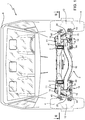
Figure 1 is a front view, with parts in section and parts removed for clarity's sake, of a light commercial vehicle manufactured according to the present invention; -
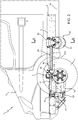
Figure 2 is a side view, with parts removed for clarity's sake, of the light commercial vehicle ofFigure 1 ; -
Figure 3 is a top view in section along the plane III-III and with parts removed for clarity's sake, of a detail ofFigure 1 ; -
Figure 4 is a rear view in section along the plane IV-IV of a detail ofFigure 2 ; and -
Figure 5 is a perspective view with parts removed for clarity's sake, of a detail ofFigure 1 . - With reference to
Figure 1 , the reference number 1 indicates a light commercial vehicle. - With reference to
Figures 1 and2 , the light commercial vehicle 1 extends along a longitudinal axis A1 and comprises: a load-bearingstructure 2; anaxle assembly 3 coupled to the load-bearingstructure 2;wheels 4 coupled to theaxle assembly 3; and twopneumatic assemblies 20 coupled to the load-bearingstructure 2 and to theaxle assembly 3. - With reference to
Figure 3 , the load-bearingstructure 2 comprises aframe 5 havinglongitudinal members 6 andcross members 7. With reference toFigures 1 and2 , the vehicle 1 comprises acab 8 mounted on theframe 5. In an alternative embodiment not shown in the attached figures, the load-bearing structure comprises a cab with a load-bearing shell. - With reference to
Figures 3 and4 , theaxle assembly 3 comprises asupport structure 10, in particular across member 10, which extends along an axis A2 which is transversal to the axis A1, preferably perpendicular to the axis A1; twosuspensions 11; and twohubs 12 articulated to thecross member 10 by means of therespective suspensions 11. - With reference to
Figure 1 and3 , eachsuspension 11 comprises amechanical joint 14 that connects in an articulated way thehub 12 to thecross member 10 and ashock absorber 15 arranged between themechanical joint 14 and thecross member 10. - In more detail, each
joint 14 comprises anupper suspension arm 16, anupper tie rod 17, alower suspension arm 18 and alower tie rod 19. - On the one hand, each
upper arm 16 is directly connected to therespective hub 12 by a respectiveupper ball joint 40 allowing a vertical steering and oscillation of thehub 12. - Moreover, on the other hand, each
upper arm 16 is connected to thecross member 10 by means of a respective uppercylindrical joint 41 at aconnection point 41a. - Each
mechanical joint 14 comprises aplate 13 connected to the load-bearingstructure 2 at aconnection point 51 different from aconnection point 50 between thecross member 10 and the load-bearingstructure 2. - The
upper tie rod 17 is connected to theupper arm 16 through aconnection element 42 and to theplate 13 at a connection point through aball joint 52. - With reference to
Figure 1 , thelower arm 18 is connected, on the one hand, directly to thehub 12 by means of alower ball joint 43 allowing the steering and the oscillation of thehub 12. Moreover, thelower arm 18 is connected, on the other hand, to thecross member 10 at a lowercylindrical joint 44. - The
lower tie rod 19 is connected to thelower arm 18 through aconnection element 45 and to theplate 13 at a connection point through a ball joint 53. - The
shock absorber 15 is arranged between thelower arm 18 and thecross member 10, at alower connection point 54. - The term ball joint means a joint that allows rotation movements about a ball centre. The term cylindrical joint means a joint that allows rotation movements about a rotation axis.
- With reference to
Figure 1 , the vehicle 1 comprises asteering system 80 that is supported by thecross member 10 of theaxle assembly 3 and is coupled to thehubs 12 to move them through the ball joints 40 and 43. - Each
pneumatic assembly 20 comprises atransmission system 21; anair spring 22; asupport structure 25 and acontrol system 26 of theair spring 22. Moreover, in a non-limiting embodiment of the present invention not shown in the accompanying figures, the pneumatic assembly comprises an air tank. - The
transmission system 21 is arranged between theair spring 22 and thesuspension 11. Thetransmission system 21 comprises atransfer element 21a, in particular a rod; and atransmission arm 21b abutting against theair spring 22. - The
transfer element 21a comprises acoupling portion 55 having at least a diameter, preferably a plurality of coupling diameters. - The
transmission system 21 is integrally connected to thesuspension 11 and in particular to theupper arm 16, in particular through thecoupling portion 55. In particular, thetransfer rod 21a is rigidly connected to theupper arm 16 at theconnection point 41a. In more detail, thetransfer rod 21a is rotatable about a rotation axis and is integrally connected to thearm 16 so as to transfer a rotation to thearm 16 or from thearm 16. In particular, thecoupling portion 55 of therod 21a is connected to thearm 16 at theconnection point 41a. - The
air spring 22 can take a plurality of configurations based on its air content. Its air content is adjustable by means of thecontrol system 26. In more detail, theair spring 22 has afirst end 27 coupled to thesuspension 11 through thetransmission system 21 and asecond end 28 coupled to the load-bearing structure 2 by means of thesupport structure 25. Thesecond end 28 is opposite thefirst end 27. Thefirst end 27 can take a plurality of positions based on the configuration of the air spring, i.e. based on the amount of air inside it. - The
support structure 25 comprises asupport element 25a for eachair spring 22 rigidly connected to thesecond end 28 of theair spring 22 and to the load-bearing structure 2 of the vehicle 1. Moreover, thesupport element 25a is connected throughelastic bushes 29 to thetransfer element 21a which, accordingly, is freely rotatable with respect to thesupport element 25a. Thesupport structure 25 comprises across member 25b rigidly connecting thesupport elements 25a. Thesupport structure 25 is connected to the load-bearing structure 2 of the vehicle 1. - The
air spring 22 comprises aninner compartment 46, defined by amembrane 47 and adapted to contain gas, that extends between theends inner compartment 46 is adjustable. Moreover, theair spring 22 comprises alower plate 23, which is in contact with thetransmission arm 21b; an end-of-travel buffer 30 housed in thecompartment 46 and anupper plate 31 housed in theend 28 and in contact with thesupport element 25a. - The end-of-
travel buffer 30 in use moves up until abutting against theupper plate 31. - In an embodiment not shown, the
plate 31 is omitted and the membrane is directly in contact with thesupport element 25a, which also operates as theplate 31. - The
control element 26 is coupled to theair spring 22 for controlling the amount of gas in theinner compartment 46. - The stiffness and the length of the
air spring 22 are thus adjustable. Based on the length of theair spring 22, thefirst end 27 takes a plurality of positions. - The
plate 23 is connected to themembrane 47 of theair spring 22 and is arranged out of themembrane 47. Theplate 23 is moved in a plurality of positions based on the plurality of positions of themembrane 47. - The
transmission arm 21b is connected to theplate 23 and to thetransfer element 21a. - In use, the
arm 21b rotates around a rotation axis depending on the configuration of theair spring 22, in particular depending on the position of thefirst end 27 of theair spring 22. The rotation axis extends along thetransfer element 21a. - Based on the position taken by the
plate 23, thearm 21b rotates thetransfer element 21a so that it takes different angular positions. On the one side, thetransfer element 21a is rigidly connected to thearm 21b and on the other side it is rigidly connected to thesuspension 11, in particular to theupper arm 16 of thesuspension 11. In more detail, when thetransfer element 21a rotates, it transmits the rotation movement to theupper arm 16 which, in turn, can rotate about the joint 41 and take a plurality of variable inclinations based on the angular position of thetransfer element 21a. In this way, the position of the vehicle 1 changes and in particular the height from the ground of the vehicle 1 changes, in particular of theframe 5 of the vehicle 1. By changing the height from the ground of theframe 5 of the vehicle 1, also the height from the ground of the floor of thecab 8 changes, and this allows tilting laterally the floor of thecab 8 to facilitate the ascent or descent of the passengers or to facilitate the loading and unloading of the vehicle 1, as well as evenly raising or lowering the floor with respect to the ground. - In other words, when the
transmission arm 21b rotates under the action of theair spring 22, it transfers the rotation to thetransfer element 21a, which rotates around the rotation axis. Thetransfer element 21a is integrally connected to thearm 16, thus transferring the rotation to thearm 16. By rotating, thearm 16 varies a position of thecross member 10 of theaxle assembly 3 with respect to the ground. By varying the position of thecross member 10 of theaxle assembly 3 it also varies a position of thecab 8 of the vehicle 1 with respect to the ground. - The
control system 26 is preferably electronic or electrical. Thecontrol system 26 can vary the gas volume in thecompartment 46 and, consequently, the configuration of thesuspensions 11 based on manual commands sent by an operator, or automatically based on commands sent by thecontrol system 26. - Moreover, each
air spring 22 is independently adjustable with respect to the other. - In an alternative non-limiting embodiment of the present invention, the pneumatic assembly comprises an air tank containing pressurized air.
- Moreover, the road holding and the comfort of the vehicle 1 can be varied by acting on the rigidity of the
air spring 22. - The shown vehicle 1 is obtainable both through an assembly process that has provided the aforesaid configuration since the manufacturing of the vehicle 1 and through a conversion process of a vehicle that was initially manufactured with non-adjustable suspensions. In particular, the vehicle 1 can be obtained by converting a light commercial vehicle having suspensions with torsion bars.
- In fact, the present invention also relates to a conversion method of a commercial vehicle with a suspension assembly having a torsion bar, in particular longitudinal with respect to the vehicle. In this case, the
pneumatic assembly 20 is supplied as a conversion kit to convert the vehicle with the torsion bar into the vehicle 1 with adjustable suspensions. - In this case, the provided conversion process comprises the following steps:
- uncoupling the torsion bar from the respective suspension at a connection point;
- removing the torsion bar;
- integrally coupling the
transmission system 21 to thesuspension 11 at theconnection point 41a, in particular integrally coupling thetransfer element 21a to thesuspension arm 16 in order to transfer a rotation movement from thetransfer element 21a to thearm 16 and vice versa. - For this purpose, the diameter of the
coupling portion 55 of therod 21a is equal to the diameter of a coupling portion of the torsion bar that has been removed. Preferably, the coupling diameters of thecoupling portion 55 of therod 21a are equal to the coupling diameters of the coupling portion of the torsion bar. - In a preferred embodiment, the method comprises a further step of removing a reaction system of the torsion bar from the load-
bearing structure 2 of the vehicle 1, in other words removing the reaction system that is fixed to the torsion bar on the opposite side with respect to the suspension. - Finally, it is evident that the axle assembly may be subject to modifications and variations without departing from the scope of the appended claims.
Claims (15)
- Pneumatic assembly for a suspension of a light commercial vehicle comprising an adjustable air spring (22) having a first end (27) with a first adjustable position; a transmission system (21) operatively connected to the air spring (22) so as to take a second position, preferably angular, based on the position of the first end (27) of the air spring (22); the transmission system (21) being configured to be connected to the suspension (11) of the vehicle (1) so as to act on a configuration of the suspension (11) based on the first position of the air spring (22).
- Pneumatic assembly according to claim 1, wherein the air spring (22) is connected to a support structure (25) that is configured to be connected to a load-bearing structure (2) of the vehicle (1).
- Pneumatic assembly according to claim 1 or 2, wherein the transmission system (21) comprises a transfer element (21a) and a transmission arm (21b); the transmission arm (21b) being operatively connected to the air spring (22) so that a position, preferably angular, of the transmission arm (21b) depends on the first position of the air spring (22); the transmission arm (21b) being integrally connected to the transfer element (21a); the transfer element (21a) being configured to be integrally connected to the suspension (11) to vary a position of the suspension (11) based on the first position of the air spring (22).
- Pneumatic assembly according to claim 3, wherein the transmission arm (21b) and the transfer element (21a) are connected to each other so that an angular position of the transfer element (21a) varies based on the position of the transmission arm (21b); and wherein the transmission system (21) is configured to transmit the angular position of the transfer element (21a) to the suspension (11), in particular to an arm (16) of the suspension (11), to change the configuration of the suspension (11).
- Pneumatic assembly according to claim 3 or 4, comprising a plate (23) abutting against the transmission system (21), in particular against the transmission arm (21b).
- Conversion kit for a light commercial vehicle comprising a suspension having a torsion bar; the kit comprising a pneumatic assembly (20) according to any one of the preceding claims, wherein the transmission system (21) is configured to be connected to the suspension (11) instead of the torsion bar, in particular having a coupling portion of the transmission system (21) with a dimension equal to a dimension of a coupling portion of the torsion bar to be removed, said dimension preferably being a diameter.
- Light commercial vehicle comprising a pneumatic assembly according to any one of claims 1 to 5; and an axle assembly (3) comprising a suspension (11) integrally connected to the pneumatic assembly (20) at a connection point (41a) preferably so as to transfer a rotation movement from the pneumatic assembly (20) to the suspension (11) and vice versa.
- Light commercial vehicle according to claim 7, wherein the axle assembly (3) comprises a support structure (10), in particular a cross member; and the suspension (11) being connected to the support structure (10) through a joint (41) at the connection point (41a).
- Light commercial vehicle according to claim 7 or 8, wherein the suspension (11) comprises a suspension arm (16); the pneumatic assembly (20) being connected to the arm (16), in particular the transmission system (21) of the pneumatic assembly (20) being connected to the arm (16) so as to vary the position, preferably angular, of the arm (16) based on the first position of the air spring (22).
- Light commercial vehicle according to any one of claims 7 to 9, wherein the arm (16) is integrally connected to a transfer element (21a) of the transmission system (21), preferably a transfer bar of the pneumatic assembly (20), in particular at a joint (41) for the connection with the support structure (10) of the axle assembly (3).
- Light commercial vehicle according to any one of claims 7 to 10; comprising a load-bearing structure (2); a cab (8) supported by the load-bearing structure (2); the axle assembly (3) being connected to the load-bearing structure (2); and wherein the pneumatic assembly (20) comprises a support structure (25) connected to the load-bearing structure (2) of the vehicle (1) preferably at a different point from the one where the axle assembly is connected to the load-bearing structure (2).
- Light commercial vehicle according to claim 11, wherein the axle assembly (3) comprises a support structure (10) which is rigidly and preferably directly connected to the load-bearing structure (2) of the vehicle (1).
- Assembly method of a light commercial vehicle; the light commercial vehicle (1) comprising an axle assembly (3) comprising a support structure (10) and a suspension (11); the method comprising the steps of: coupling an adjustable air spring (22) configured to take a plurality of positions to a transmission system (21), so that the transmission system (21) rotates when the position of the air spring changes; integrally coupling the transmission system (21) to the suspension (11) of the vehicle (1) at a connection point (41a) so as to transfer a rotation from the transmission system (21) to the suspension (11) and vice versa.
- Assembly method of a light commercial vehicle of claim 13; comprising the steps of connecting the suspension (11) to the support structure (10) of the axle assembly (3) through a joint (41) at the connection point (41a).
- Conversion method of a light commercial vehicle; wherein the commercial vehicle (1) comprises a suspension (11) having a torsion bar; the method comprising the steps of the assembly method of claims 13 or 14; the method comprising the steps of removing the torsion bar from the suspension of the vehicle (1); and coupling the transmission system (21) to the suspension (11) of the commercial vehicle (1) at the connection point (41a) instead of the torsion bar.
Applications Claiming Priority (1)
| Application Number | Priority Date | Filing Date | Title |
|---|---|---|---|
| ITUA2016A003082A ITUA20163082A1 (en) | 2016-05-02 | 2016-05-02 | A PNEUMATIC GROUP FOR A LIGHT COMMERCIAL VEHICLE; THE LIGHT TRADE VEHICLE; AND A METHOD OF ASSEMBLY OF THE LIGHT TRADE VEHICLE |
Publications (2)
| Publication Number | Publication Date |
|---|---|
| EP3241694A1 true EP3241694A1 (en) | 2017-11-08 |
| EP3241694B1 EP3241694B1 (en) | 2020-07-15 |
Family
ID=56894044
Family Applications (1)
| Application Number | Title | Priority Date | Filing Date |
|---|---|---|---|
| EP17169150.4A Not-in-force EP3241694B1 (en) | 2016-05-02 | 2017-05-02 | A pneumatic assembly for a light commercial vehicle; the light commercial vehicle; and an assembly method of the light commercial vehicle |
Country Status (2)
| Country | Link |
|---|---|
| EP (1) | EP3241694B1 (en) |
| IT (1) | ITUA20163082A1 (en) |
Citations (4)
| Publication number | Priority date | Publication date | Assignee | Title |
|---|---|---|---|---|
| DE953228C (en) * | 1954-09-23 | 1956-11-29 | Augsburg Nuernberg A G Zweigni | Arrangement of air suspension in motor vehicles |
| EP0275407A1 (en) * | 1986-11-25 | 1988-07-27 | IVECO FIAT S.p.A. | Unit for elastically suspending the wheels from the frame of a motor vehicle |
| EP0464412A1 (en) * | 1990-07-04 | 1992-01-08 | Bergische Achsenfabrik Fr. Kotz & Söhne | Pneumatical suspension with longitudinal arms |
| EP1707408A1 (en) * | 2005-04-01 | 2006-10-04 | HMT Vehicles Limited | Vehicle suspension systems |
-
2016
- 2016-05-02 IT ITUA2016A003082A patent/ITUA20163082A1/en unknown
-
2017
- 2017-05-02 EP EP17169150.4A patent/EP3241694B1/en not_active Not-in-force
Patent Citations (4)
| Publication number | Priority date | Publication date | Assignee | Title |
|---|---|---|---|---|
| DE953228C (en) * | 1954-09-23 | 1956-11-29 | Augsburg Nuernberg A G Zweigni | Arrangement of air suspension in motor vehicles |
| EP0275407A1 (en) * | 1986-11-25 | 1988-07-27 | IVECO FIAT S.p.A. | Unit for elastically suspending the wheels from the frame of a motor vehicle |
| EP0464412A1 (en) * | 1990-07-04 | 1992-01-08 | Bergische Achsenfabrik Fr. Kotz & Söhne | Pneumatical suspension with longitudinal arms |
| EP1707408A1 (en) * | 2005-04-01 | 2006-10-04 | HMT Vehicles Limited | Vehicle suspension systems |
Also Published As
| Publication number | Publication date |
|---|---|
| ITUA20163082A1 (en) | 2017-11-02 |
| EP3241694B1 (en) | 2020-07-15 |
Similar Documents
| Publication | Publication Date | Title |
|---|---|---|
| CN106457939B (en) | vehicle suspension | |
| JP5784509B2 (en) | Automotive suspension | |
| US9010782B2 (en) | Vehicle with a four bar link suspension system provided with improved roll characteristics | |
| US6685203B1 (en) | Individual wheel suspension | |
| WO2005058620A1 (en) | Vehicle with movable and inwardly tilting safety body | |
| US8146939B2 (en) | Roll-stabilizing fifth wheel apparatus | |
| US7246808B2 (en) | Wheel suspension for vehicles | |
| EP1789268B1 (en) | Wheel suspension | |
| KR20110058462A (en) | Suspension of automobile | |
| EP2990239B1 (en) | Semitrailer equipped with independent wheel suspension and air springs | |
| EP3241694B1 (en) | A pneumatic assembly for a light commercial vehicle; the light commercial vehicle; and an assembly method of the light commercial vehicle | |
| CN105365510A (en) | Vehicle suspension | |
| EP0847883B1 (en) | Motor-vehicle rear suspension | |
| HU212319B (en) | Axle with longitudinal arms for motor vehicles and trailers | |
| CN106029406B (en) | The motor vehicles mounted with improved hanging part | |
| EP0589273B1 (en) | Rear suspension system for independent wheels of motor vehicles | |
| US20080303237A1 (en) | Idividual Wheel Suspension | |
| EP4534303A1 (en) | Independent suspension | |
| US8528922B2 (en) | Chassis | |
| US20050253354A1 (en) | Horizontal shock suspension system | |
| CN111655520B (en) | Wheel suspension device, holding device for automobile and automobile | |
| KR20030017669A (en) | Rear suspension system for vehicles | |
| EP0196147B1 (en) | Method of manufacturing vehicles | |
| KR0130374Y1 (en) | Rear suspension apparatus for a vehicle | |
| PL166446B1 (en) | Suspension system in particular for motor vehicles |
Legal Events
| Date | Code | Title | Description |
|---|---|---|---|
| PUAI | Public reference made under article 153(3) epc to a published international application that has entered the european phase |
Free format text: ORIGINAL CODE: 0009012 |
|
| STAA | Information on the status of an ep patent application or granted ep patent |
Free format text: STATUS: THE APPLICATION HAS BEEN PUBLISHED |
|
| AK | Designated contracting states |
Kind code of ref document: A1 Designated state(s): AL AT BE BG CH CY CZ DE DK EE ES FI FR GB GR HR HU IE IS IT LI LT LU LV MC MK MT NL NO PL PT RO RS SE SI SK SM TR |
|
| AX | Request for extension of the european patent |
Extension state: BA ME |
|
| STAA | Information on the status of an ep patent application or granted ep patent |
Free format text: STATUS: REQUEST FOR EXAMINATION WAS MADE |
|
| 17P | Request for examination filed |
Effective date: 20180508 |
|
| RBV | Designated contracting states (corrected) |
Designated state(s): AL AT BE BG CH CY CZ DE DK EE ES FI FR GB GR HR HU IE IS IT LI LT LU LV MC MK MT NL NO PL PT RO RS SE SI SK SM TR |
|
| STAA | Information on the status of an ep patent application or granted ep patent |
Free format text: STATUS: EXAMINATION IS IN PROGRESS |
|
| 17Q | First examination report despatched |
Effective date: 20190304 |
|
| GRAP | Despatch of communication of intention to grant a patent |
Free format text: ORIGINAL CODE: EPIDOSNIGR1 |
|
| STAA | Information on the status of an ep patent application or granted ep patent |
Free format text: STATUS: GRANT OF PATENT IS INTENDED |
|
| INTG | Intention to grant announced |
Effective date: 20200128 |
|
| GRAS | Grant fee paid |
Free format text: ORIGINAL CODE: EPIDOSNIGR3 |
|
| GRAA | (expected) grant |
Free format text: ORIGINAL CODE: 0009210 |
|
| STAA | Information on the status of an ep patent application or granted ep patent |
Free format text: STATUS: THE PATENT HAS BEEN GRANTED |
|
| AK | Designated contracting states |
Kind code of ref document: B1 Designated state(s): AL AT BE BG CH CY CZ DE DK EE ES FI FR GB GR HR HU IE IS IT LI LT LU LV MC MK MT NL NO PL PT RO RS SE SI SK SM TR |
|
| REG | Reference to a national code |
Ref country code: CH Ref legal event code: EP Ref country code: GB Ref legal event code: FG4D |
|
| REG | Reference to a national code |
Ref country code: IE Ref legal event code: FG4D |
|
| REG | Reference to a national code |
Ref country code: DE Ref legal event code: R096 Ref document number: 602017019663 Country of ref document: DE |
|
| REG | Reference to a national code |
Ref country code: AT Ref legal event code: REF Ref document number: 1290628 Country of ref document: AT Kind code of ref document: T Effective date: 20200815 |
|
| REG | Reference to a national code |
Ref country code: LT Ref legal event code: MG4D |
|
| REG | Reference to a national code |
Ref country code: NL Ref legal event code: MP Effective date: 20200715 |
|
| PG25 | Lapsed in a contracting state [announced via postgrant information from national office to epo] |
Ref country code: FI Free format text: LAPSE BECAUSE OF FAILURE TO SUBMIT A TRANSLATION OF THE DESCRIPTION OR TO PAY THE FEE WITHIN THE PRESCRIBED TIME-LIMIT Effective date: 20200715 Ref country code: LT Free format text: LAPSE BECAUSE OF FAILURE TO SUBMIT A TRANSLATION OF THE DESCRIPTION OR TO PAY THE FEE WITHIN THE PRESCRIBED TIME-LIMIT Effective date: 20200715 Ref country code: PT Free format text: LAPSE BECAUSE OF FAILURE TO SUBMIT A TRANSLATION OF THE DESCRIPTION OR TO PAY THE FEE WITHIN THE PRESCRIBED TIME-LIMIT Effective date: 20201116 Ref country code: BG Free format text: LAPSE BECAUSE OF FAILURE TO SUBMIT A TRANSLATION OF THE DESCRIPTION OR TO PAY THE FEE WITHIN THE PRESCRIBED TIME-LIMIT Effective date: 20201015 Ref country code: NO Free format text: LAPSE BECAUSE OF FAILURE TO SUBMIT A TRANSLATION OF THE DESCRIPTION OR TO PAY THE FEE WITHIN THE PRESCRIBED TIME-LIMIT Effective date: 20201015 Ref country code: GR Free format text: LAPSE BECAUSE OF FAILURE TO SUBMIT A TRANSLATION OF THE DESCRIPTION OR TO PAY THE FEE WITHIN THE PRESCRIBED TIME-LIMIT Effective date: 20201016 Ref country code: ES Free format text: LAPSE BECAUSE OF FAILURE TO SUBMIT A TRANSLATION OF THE DESCRIPTION OR TO PAY THE FEE WITHIN THE PRESCRIBED TIME-LIMIT Effective date: 20200715 Ref country code: SE Free format text: LAPSE BECAUSE OF FAILURE TO SUBMIT A TRANSLATION OF THE DESCRIPTION OR TO PAY THE FEE WITHIN THE PRESCRIBED TIME-LIMIT Effective date: 20200715 Ref country code: HR Free format text: LAPSE BECAUSE OF FAILURE TO SUBMIT A TRANSLATION OF THE DESCRIPTION OR TO PAY THE FEE WITHIN THE PRESCRIBED TIME-LIMIT Effective date: 20200715 |
|
| PG25 | Lapsed in a contracting state [announced via postgrant information from national office to epo] |
Ref country code: RS Free format text: LAPSE BECAUSE OF FAILURE TO SUBMIT A TRANSLATION OF THE DESCRIPTION OR TO PAY THE FEE WITHIN THE PRESCRIBED TIME-LIMIT Effective date: 20200715 Ref country code: PL Free format text: LAPSE BECAUSE OF FAILURE TO SUBMIT A TRANSLATION OF THE DESCRIPTION OR TO PAY THE FEE WITHIN THE PRESCRIBED TIME-LIMIT Effective date: 20200715 Ref country code: LV Free format text: LAPSE BECAUSE OF FAILURE TO SUBMIT A TRANSLATION OF THE DESCRIPTION OR TO PAY THE FEE WITHIN THE PRESCRIBED TIME-LIMIT Effective date: 20200715 Ref country code: IS Free format text: LAPSE BECAUSE OF FAILURE TO SUBMIT A TRANSLATION OF THE DESCRIPTION OR TO PAY THE FEE WITHIN THE PRESCRIBED TIME-LIMIT Effective date: 20201115 |
|
| REG | Reference to a national code |
Ref country code: AT Ref legal event code: UEP Ref document number: 1290628 Country of ref document: AT Kind code of ref document: T Effective date: 20200715 |
|
| PG25 | Lapsed in a contracting state [announced via postgrant information from national office to epo] |
Ref country code: NL Free format text: LAPSE BECAUSE OF FAILURE TO SUBMIT A TRANSLATION OF THE DESCRIPTION OR TO PAY THE FEE WITHIN THE PRESCRIBED TIME-LIMIT Effective date: 20200715 |
|
| REG | Reference to a national code |
Ref country code: DE Ref legal event code: R097 Ref document number: 602017019663 Country of ref document: DE |
|
| PG25 | Lapsed in a contracting state [announced via postgrant information from national office to epo] |
Ref country code: EE Free format text: LAPSE BECAUSE OF FAILURE TO SUBMIT A TRANSLATION OF THE DESCRIPTION OR TO PAY THE FEE WITHIN THE PRESCRIBED TIME-LIMIT Effective date: 20200715 Ref country code: SM Free format text: LAPSE BECAUSE OF FAILURE TO SUBMIT A TRANSLATION OF THE DESCRIPTION OR TO PAY THE FEE WITHIN THE PRESCRIBED TIME-LIMIT Effective date: 20200715 Ref country code: CZ Free format text: LAPSE BECAUSE OF FAILURE TO SUBMIT A TRANSLATION OF THE DESCRIPTION OR TO PAY THE FEE WITHIN THE PRESCRIBED TIME-LIMIT Effective date: 20200715 Ref country code: DK Free format text: LAPSE BECAUSE OF FAILURE TO SUBMIT A TRANSLATION OF THE DESCRIPTION OR TO PAY THE FEE WITHIN THE PRESCRIBED TIME-LIMIT Effective date: 20200715 Ref country code: RO Free format text: LAPSE BECAUSE OF FAILURE TO SUBMIT A TRANSLATION OF THE DESCRIPTION OR TO PAY THE FEE WITHIN THE PRESCRIBED TIME-LIMIT Effective date: 20200715 |
|
| PLBE | No opposition filed within time limit |
Free format text: ORIGINAL CODE: 0009261 |
|
| STAA | Information on the status of an ep patent application or granted ep patent |
Free format text: STATUS: NO OPPOSITION FILED WITHIN TIME LIMIT |
|
| PG25 | Lapsed in a contracting state [announced via postgrant information from national office to epo] |
Ref country code: AL Free format text: LAPSE BECAUSE OF FAILURE TO SUBMIT A TRANSLATION OF THE DESCRIPTION OR TO PAY THE FEE WITHIN THE PRESCRIBED TIME-LIMIT Effective date: 20200715 |
|
| 26N | No opposition filed |
Effective date: 20210416 |
|
| PG25 | Lapsed in a contracting state [announced via postgrant information from national office to epo] |
Ref country code: SK Free format text: LAPSE BECAUSE OF FAILURE TO SUBMIT A TRANSLATION OF THE DESCRIPTION OR TO PAY THE FEE WITHIN THE PRESCRIBED TIME-LIMIT Effective date: 20200715 |
|
| PG25 | Lapsed in a contracting state [announced via postgrant information from national office to epo] |
Ref country code: SI Free format text: LAPSE BECAUSE OF FAILURE TO SUBMIT A TRANSLATION OF THE DESCRIPTION OR TO PAY THE FEE WITHIN THE PRESCRIBED TIME-LIMIT Effective date: 20200715 |
|
| REG | Reference to a national code |
Ref country code: CH Ref legal event code: PL |
|
| PG25 | Lapsed in a contracting state [announced via postgrant information from national office to epo] |
Ref country code: CH Free format text: LAPSE BECAUSE OF NON-PAYMENT OF DUE FEES Effective date: 20210531 Ref country code: LI Free format text: LAPSE BECAUSE OF NON-PAYMENT OF DUE FEES Effective date: 20210531 Ref country code: MC Free format text: LAPSE BECAUSE OF FAILURE TO SUBMIT A TRANSLATION OF THE DESCRIPTION OR TO PAY THE FEE WITHIN THE PRESCRIBED TIME-LIMIT Effective date: 20200715 Ref country code: LU Free format text: LAPSE BECAUSE OF NON-PAYMENT OF DUE FEES Effective date: 20210502 |
|
| REG | Reference to a national code |
Ref country code: BE Ref legal event code: MM Effective date: 20210531 |
|
| PG25 | Lapsed in a contracting state [announced via postgrant information from national office to epo] |
Ref country code: IE Free format text: LAPSE BECAUSE OF NON-PAYMENT OF DUE FEES Effective date: 20210502 |
|
| PG25 | Lapsed in a contracting state [announced via postgrant information from national office to epo] |
Ref country code: FR Free format text: LAPSE BECAUSE OF NON-PAYMENT OF DUE FEES Effective date: 20210531 |
|
| PG25 | Lapsed in a contracting state [announced via postgrant information from national office to epo] |
Ref country code: BE Free format text: LAPSE BECAUSE OF NON-PAYMENT OF DUE FEES Effective date: 20210531 |
|
| PG25 | Lapsed in a contracting state [announced via postgrant information from national office to epo] |
Ref country code: HU Free format text: LAPSE BECAUSE OF FAILURE TO SUBMIT A TRANSLATION OF THE DESCRIPTION OR TO PAY THE FEE WITHIN THE PRESCRIBED TIME-LIMIT; INVALID AB INITIO Effective date: 20170502 |
|
| P01 | Opt-out of the competence of the unified patent court (upc) registered |
Effective date: 20230512 |
|
| PG25 | Lapsed in a contracting state [announced via postgrant information from national office to epo] |
Ref country code: CY Free format text: LAPSE BECAUSE OF FAILURE TO SUBMIT A TRANSLATION OF THE DESCRIPTION OR TO PAY THE FEE WITHIN THE PRESCRIBED TIME-LIMIT Effective date: 20200715 |
|
| PGFP | Annual fee paid to national office [announced via postgrant information from national office to epo] |
Ref country code: IT Payment date: 20230509 Year of fee payment: 7 Ref country code: DE Payment date: 20230530 Year of fee payment: 7 |
|
| PGFP | Annual fee paid to national office [announced via postgrant information from national office to epo] |
Ref country code: AT Payment date: 20230519 Year of fee payment: 7 |
|
| PGFP | Annual fee paid to national office [announced via postgrant information from national office to epo] |
Ref country code: GB Payment date: 20230523 Year of fee payment: 7 |
|
| PG25 | Lapsed in a contracting state [announced via postgrant information from national office to epo] |
Ref country code: MK Free format text: LAPSE BECAUSE OF FAILURE TO SUBMIT A TRANSLATION OF THE DESCRIPTION OR TO PAY THE FEE WITHIN THE PRESCRIBED TIME-LIMIT Effective date: 20200715 |
|
| PG25 | Lapsed in a contracting state [announced via postgrant information from national office to epo] |
Ref country code: MT Free format text: LAPSE BECAUSE OF FAILURE TO SUBMIT A TRANSLATION OF THE DESCRIPTION OR TO PAY THE FEE WITHIN THE PRESCRIBED TIME-LIMIT Effective date: 20200715 |
|
| REG | Reference to a national code |
Ref country code: DE Ref legal event code: R119 Ref document number: 602017019663 Country of ref document: DE |
|
| REG | Reference to a national code |
Ref country code: AT Ref legal event code: MM01 Ref document number: 1290628 Country of ref document: AT Kind code of ref document: T Effective date: 20240502 |
|
| PG25 | Lapsed in a contracting state [announced via postgrant information from national office to epo] |
Ref country code: AT Free format text: LAPSE BECAUSE OF NON-PAYMENT OF DUE FEES Effective date: 20240502 |
|
| GBPC | Gb: european patent ceased through non-payment of renewal fee |
Effective date: 20240502 |
|
| PG25 | Lapsed in a contracting state [announced via postgrant information from national office to epo] |
Ref country code: AT Free format text: LAPSE BECAUSE OF NON-PAYMENT OF DUE FEES Effective date: 20240502 |
|
| PG25 | Lapsed in a contracting state [announced via postgrant information from national office to epo] |
Ref country code: DE Free format text: LAPSE BECAUSE OF NON-PAYMENT OF DUE FEES Effective date: 20241203 |
|
| PG25 | Lapsed in a contracting state [announced via postgrant information from national office to epo] |
Ref country code: GB Free format text: LAPSE BECAUSE OF NON-PAYMENT OF DUE FEES Effective date: 20240502 Ref country code: IT Free format text: LAPSE BECAUSE OF NON-PAYMENT OF DUE FEES Effective date: 20240502 |
|
| PG25 | Lapsed in a contracting state [announced via postgrant information from national office to epo] |
Ref country code: TR Free format text: LAPSE BECAUSE OF FAILURE TO SUBMIT A TRANSLATION OF THE DESCRIPTION OR TO PAY THE FEE WITHIN THE PRESCRIBED TIME-LIMIT Effective date: 20200715 |