EP3240462B1 - A cleaning apparatus for cleaning filter screens - Google Patents
A cleaning apparatus for cleaning filter screens Download PDFInfo
- Publication number
- EP3240462B1 EP3240462B1 EP16732887.1A EP16732887A EP3240462B1 EP 3240462 B1 EP3240462 B1 EP 3240462B1 EP 16732887 A EP16732887 A EP 16732887A EP 3240462 B1 EP3240462 B1 EP 3240462B1
- Authority
- EP
- European Patent Office
- Prior art keywords
- filter screen
- suction chamber
- dirt collection
- conduit system
- collection conduit
- Prior art date
- Legal status (The legal status is an assumption and is not a legal conclusion. Google has not performed a legal analysis and makes no representation as to the accuracy of the status listed.)
- Active
Links
- 238000004140 cleaning Methods 0.000 title claims description 54
- 239000012530 fluid Substances 0.000 claims description 21
- 239000012465 retentate Substances 0.000 claims description 13
- 238000010926 purge Methods 0.000 claims description 9
- 230000002093 peripheral effect Effects 0.000 claims description 6
- 238000004891 communication Methods 0.000 claims description 4
- 238000001914 filtration Methods 0.000 description 11
- XLYOFNOQVPJJNP-UHFFFAOYSA-N water Substances O XLYOFNOQVPJJNP-UHFFFAOYSA-N 0.000 description 9
- 238000000034 method Methods 0.000 description 5
- 239000000356 contaminant Substances 0.000 description 4
- 239000000428 dust Substances 0.000 description 2
- 239000007788 liquid Substances 0.000 description 2
- 238000004519 manufacturing process Methods 0.000 description 2
- 238000009825 accumulation Methods 0.000 description 1
- 230000000712 assembly Effects 0.000 description 1
- 238000000429 assembly Methods 0.000 description 1
- 230000015572 biosynthetic process Effects 0.000 description 1
- 238000010276 construction Methods 0.000 description 1
- 238000011109 contamination Methods 0.000 description 1
- 238000000605 extraction Methods 0.000 description 1
- 238000011010 flushing procedure Methods 0.000 description 1
- 230000000977 initiatory effect Effects 0.000 description 1
- 230000000717 retained effect Effects 0.000 description 1
- 230000001960 triggered effect Effects 0.000 description 1
- 238000012800 visualization Methods 0.000 description 1
- 238000005406 washing Methods 0.000 description 1
Images


Classifications
-
- B—PERFORMING OPERATIONS; TRANSPORTING
- B01—PHYSICAL OR CHEMICAL PROCESSES OR APPARATUS IN GENERAL
- B01D—SEPARATION
- B01D29/00—Filters with filtering elements stationary during filtration, e.g. pressure or suction filters, not covered by groups B01D24/00 - B01D27/00; Filtering elements therefor
- B01D29/11—Filters with filtering elements stationary during filtration, e.g. pressure or suction filters, not covered by groups B01D24/00 - B01D27/00; Filtering elements therefor with bag, cage, hose, tube, sleeve or like filtering elements
- B01D29/114—Filters with filtering elements stationary during filtration, e.g. pressure or suction filters, not covered by groups B01D24/00 - B01D27/00; Filtering elements therefor with bag, cage, hose, tube, sleeve or like filtering elements arranged for inward flow filtration
-
- B—PERFORMING OPERATIONS; TRANSPORTING
- B01—PHYSICAL OR CHEMICAL PROCESSES OR APPARATUS IN GENERAL
- B01D—SEPARATION
- B01D29/00—Filters with filtering elements stationary during filtration, e.g. pressure or suction filters, not covered by groups B01D24/00 - B01D27/00; Filtering elements therefor
- B01D29/62—Regenerating the filter material in the filter
- B01D29/64—Regenerating the filter material in the filter by scrapers, brushes, nozzles, or the like, acting on the cake side of the filtering element
- B01D29/6438—Regenerating the filter material in the filter by scrapers, brushes, nozzles, or the like, acting on the cake side of the filtering element nozzles
-
- B—PERFORMING OPERATIONS; TRANSPORTING
- B01—PHYSICAL OR CHEMICAL PROCESSES OR APPARATUS IN GENERAL
- B01D—SEPARATION
- B01D29/00—Filters with filtering elements stationary during filtration, e.g. pressure or suction filters, not covered by groups B01D24/00 - B01D27/00; Filtering elements therefor
- B01D29/62—Regenerating the filter material in the filter
- B01D29/66—Regenerating the filter material in the filter by flushing, e.g. counter-current air-bumps
- B01D29/68—Regenerating the filter material in the filter by flushing, e.g. counter-current air-bumps with backwash arms, shoes or nozzles
-
- B—PERFORMING OPERATIONS; TRANSPORTING
- B01—PHYSICAL OR CHEMICAL PROCESSES OR APPARATUS IN GENERAL
- B01D—SEPARATION
- B01D29/00—Filters with filtering elements stationary during filtration, e.g. pressure or suction filters, not covered by groups B01D24/00 - B01D27/00; Filtering elements therefor
- B01D29/01—Filters with filtering elements stationary during filtration, e.g. pressure or suction filters, not covered by groups B01D24/00 - B01D27/00; Filtering elements therefor with flat filtering elements
-
- C—CHEMISTRY; METALLURGY
- C02—TREATMENT OF WATER, WASTE WATER, SEWAGE, OR SLUDGE
- C02F—TREATMENT OF WATER, WASTE WATER, SEWAGE, OR SLUDGE
- C02F2303/00—Specific treatment goals
- C02F2303/24—Separation of coarse particles, e.g. by using sieves or screens
Definitions
- This invention generally relates to a cleaning apparatus for cleaning filter screens and specifically to cleaning apparatus for cleaning filter screens having nozzles for creating suction.
- This invention finds particular, but not exclusive, application in industries employing filter screens for filtering purposes.
- Dust extraction assemblies for removing contamination are constructed of a plurality of nozzles at pre-defined distances from the surface of filter element. Such nozzles are connected to collector pipe which moves with the help of hydraulics or electric motors. A purge valve is connected to the dust collector pipe which opens to the atmosphere. Cleaning of the filter screen is done automatically either on the basis of differential pressure between filter housing and pressure at the purge valve outlet (atmospheric pressure) or it can be done according to preset time interval.
- WO2014027715A1 relates to a multicage-type apparatus for filtering ballast water in which a plurality of filtering units are packetized and connected inside a body from which ballast water is introduced or discharged, and to a method for same, and more specifically, to a multicage-type apparatus for filtering ballast water for automatically controlling simultaneous reverse-washing.
- a suction nozzle assembly comprising a tube coupled to a pressure sink at a distal side thereof, a nozzle, a resilient element which couples said nozzle to a proximal side of said tube and a deformable housing which bridges a gap between said proximal side of said tube and said nozzle.
- a pressure equalizer for example, a through aperture, is formed in said nozzle.
- a cleaning apparatus for cleaning filter screen comprising a suction chamber movably positioned adjacent a filter screen to be cleaned such that a first end of the suction chamber is positioned adjacent an inner surface of the filter screen and a second end of the suction chamber being coupled to a dirt collection conduit system for fluid communication with the dirt collection system.
- the outer surface of the filter screen is arranged to be at a higher pressure than the dirt collection conduit system such that a pressure differential is arranged to be maintained between the outer surface of the filter screen and the dirt collection conduit system through the suction chamber.
- the suction chamber further comprises a nozzle at the first end, wherein a largest diameter of the nozzle is lesser than an inner diameter of the suction chamber, the nozzle and the suction chamber arranged concentrically.
- the suction chamber further comprises a circular clearance between the largest diameter of the nozzle and the inner diameter of the suction chamber.
- the pressure differential is arranged to facilitate movement of fluid from the outer surface of the filter screen to the dirt collection conduit system and wherein the fluid movement through the nozzle of the suction chamber creates a low pressure regime around a mouth of the nozzle inside the suction chamber, thereby facilitating fluid from the outer surface of the filter screen to rush towards the low pressure regime through the circular clearance, thus removing retentate forcefully from the inner surface of the filter screen.
- FIG. 1 shows a screen filtering system 100 with a cleaning apparatus 200 for cleaning the filter screen 105 in the screen filtering system 100.
- the screen filtering system 100 comprises a housing 110 which is circular in profile.
- the screen filter 105 is fitted by way of suitable fastening arrangements to the housing 110 internally, the fastening arrangements being water proof.
- the housing 110 and the filter screen 105 are concentric cylinders with the filter screen 105 arranged internally to the housing 110.
- the screen filtering system 100 further comprises an inlet pipe 115 which opens into a chamber 120 internal to the filter screen 105.
- the water that is pressurized passes through the filter screen 105 into the circular clearance or interval 125 between the filter screen 105 and the housing 110 and exist through an exit pipe 130 which is controlled by a valve 135.
- the contaminants in the fluid get accumulated on an inner surface 140 of the filter screen 105.
- the accumulated contaminants form as retentate on the inner or internal surface 140 of the filter screen 105.
- FIG. 2 shows a first embodiment of the cleaning apparatus 200.
- the cleaning apparatus 200 comprises a suction chamber 205, which is a cylindrical element of constant diameter that is movably positioned adjacent the filter screen 105 to be cleaned.
- the suction chamber 205 is positioned in such a way that it is orthogonal to the filter screen 105.
- the suction chamber 205 comprises a first end 210 adjacent the inner surface 140 of the filter screen 105 and a second end 215 of the suction chamber 205 coupled to a dirt collection conduit system 220.
- the dirt collection conduit system 220 extends along an axis 110' of the housing 110.
- the suction chamber 205 extends from the dirt collection conduit system 220 to the inner surface 140 of the filter screen.
- the suction chamber 205 is orthogonal to the axis 110' as well.
- the suction chamber 205 is coupled to the dirt collection conduit system 220 such that there is fluid communication between the suction chamber 205 and the dirt collection conduit system 220.
- the filter screen comprises an outer or external surface 145 which is arranged to be at atmospheric pressure or a pressure higher than that when the cleaning apparatus 200 is being used.
- the dirt collection conduit system 220 extends along the axis 110' of the housing 110 and opens out externally through a purge outlet 150 and a purging valve 155.
- the purge outlet 150 is connected to a low pressure environment when the cleaning apparatus 200 is being used. Thus, when the cleaning apparatus 200 is being used, there is maintained a pressure differential between the outer surface or external surface 145 and the dirt collection conduit system 220.
- the suction chamber 205 further comprises a central nozzle 225 attached to the first end 210 of the suction chamber 205.
- the central nozzle 225 is such that a largest diameter of the central nozzle 225 is lesser than an inner diameter of the suction chamber 205.
- the central nozzle 225 and the suction chamber 205 are arranged concentrically. Between the largest diameter of the central nozzle 225 and the inner diameter of the suction chamber 205 is a circular clearance 230 in which is circularly arranged a plurality of peripheral suction nozzles 235.
- the cleaning apparatus 200 is activated by initiating and maintaining a pressure differential between the outer surface 145 of the filter screen 105 and the dirt collection conduit system 220.
- This pressure differential causes movement of fluid from the outer surface 145 of the filter screen 105 to the dirt collection conduit system 220 through the suction chamber 205.
- a low pressure regime 240 is created around and in proximity to a mouth 245 of the central nozzle 225 inside the suction chamber 205.
- This low pressure regime 240 acts as a suction force to suck or pull fluid from the outer surface 145 of the filter screen 105 to rush towards the low pressure regime 240, such that the retentate accumulated in the inner surface 140 of the filter screen 105 is forcefully removed.
- the low pressure regime is formed due to increased velocity which is due to the convergence in the section of the nozzle 225.
- the pressure differential due to the low pressure regime 240 created is more than the pressure differential between the outer surface 145 of the filter screen 105 and the purge outlet 150 through the dirt collection conduit system 220.
- the suction chamber 205 is arranged to rotate about an axis 110' of the dirt collection conduit system 220.
- the axis 110' of the dirt collection conduit system 220 is the same as the axis 110' of the housing 110, as the dirt collection conduit system 220 extends along the axis 110' of the housing 110.
- the rotation of the suction chamber 205 is meant to remove the retentate from a circular portion of the cylindrical filter screen 105.
- one complete rotation of the suction chamber 205 about the axis 110' of the dirt collection conduit system 220 when the cleaning apparatus 200 is functioning results in the removal of retentate circularly from the filter screen 105.
- the cleaning apparatus 200 further comprises a plurality of suction chambers 205 coupled rotatably to the dirt collection conduit system 220 at different positions along the axis 110' of the dirt collection conduit system 220.
- the number of rotatable suction chambers 205 can vary anywhere from 2 to 5 or more depending on the length of the filter screen 105 inside the housing 110.
- the advantage of having a plurality of suction chambers 205 is to cover the entire surface area of the filter screen 105.
- the rotation of the suction chambers 205 is achieved by hydraulic or electric rotating techniques, which is understood by a person skilled in the art.
- the principle of working of the plurality of suction chambers 205 are the same as described above.
- the dirt collection conduit system 220 further comprises a plurality of nozzles 250 arranged inside a conduit 255 of the dirt collection conduit system 220, such that the number of nozzles 250 is the same as the number of suction chambers 205.
- One nozzle among the plurality of nozzles 250 is associated with one suction chamber within the plurality of suction chambers 205.
- Each nozzle among the plurality of nozzles 250 creates a low pressure regime near the mouth of the nozzle which enhances or adds up the suction force inside the suction chambers 205 triggered by the existence of the pressure differential between the outer surface 145 of the filter screen 105 and the dirt collection conduit system 220. This is described in detail hereinafter.
- the central nozzle 225 comprises a first portion 260 with a constant cross sectional area and a second portion 265 with a converging cross sectional area.
- the first portion 260 is proximal and adjacent to the first end 210 of the suction chamber 205 and the second portion 265 is distal to the first end 210 of the suction chamber 205.
- Figure 3 shows a divergent cone 270 disposed in the suction chamber 205 of the first embodiment of the cleaning apparatus 200.
- the suction chamber 205 can additionally comprise a divergent cone 270 extending from an opening or mouth of the second portion 265 to the second end 215 of the suction chamber 205 leaving a gap around 265.
- Divergent cone 270 facilitates streamlining of fluid ejected from the second portion 265 of the nozzle 225.
- the low pressure regime 240 is generated inside the divergent nozzle 270 near the mouth of the second portion 265.
- the angle of the second portion 265 is ⁇ and the angle of the divergent cone 270 is ⁇ .
- the optimum values for ⁇ and ⁇ can be 30° to 50° and 1° to 10° respectively.
- FIG. 4 shows a second embodiment of the cleaning apparatus 200.
- the central nozzle 225 comprises a converging portion 275.
- the second embodiment of the cleaning apparatus 200 is easy to manufacture resulting in lesser cost of manufacture.
- Near the mouth of the central nozzle 225 is created the low pressure regime 240.
- the central nozzle 225 and the suction chamber 205 are arranged coaxially.
- the circular clearance 230 comprises a plurality of peripheral suction nozzles 235 arranged circularly in the circular clearance 230.
- the low pressure regime 240 enables fluid to be sucked in forcefully through the plurality of suction nozzles 235, so as to remove the retentate from the inner surface 140 of the filter screen 105.
- the central nozzle 225 and the nozzles 250 of the dirt collection conduit system work on the principle of venturi in producing a low pressure regime and associated suction.
- the central nozzle 225 in all the embodiments mentioned can be circular, elliptical, rectangular or any other polygonal shape.
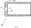
- the second embodiment as mentioned above can be achieved with the help of an orifice plate as illustrated in Figures 5a and 5b .
- Figure 5a shows a front elevational view of an orifice plate 280.
- Figure 5b shows a longitudinal sectional view along section A-A of the orifice plate 280 shown in Figure 5a .
- the suction chamber 205 is fitted with the orifice plate 280 at the first end 210 such that the orifice plate 280 fits over the central nozzle 225.
- the orifice plate 280 has a bore 285 which fits over the central nozzle 225 of the suction chamber 205.
- the bore 285 comprises a principal circular bore 290 and a secondary circular bore 295.
- the principal circular bore 290 and the secondary circular bore 295 are coaxial and matches with the dimensions of the central nozzle 225 to provide a good fit for the orifice plate 280 over the central nozzle 225.
- the orifice plate comprises a plurality of holes 296 in the periphery and surrounding the bore 285 to form the plurality of peripheral suction nozzles 235.
- the external surface of the suction chamber 205 can be circular, elliptical or any polygonal shape.
- the internal surface and cavity of the suction chamber 205 is cylindrical.
- an externally elliptically shaped suction chamber 205 it is arranged in the housing 100 in such a way that the major axis makes an angle ⁇ with a horizontal plane.
- the suction chamber 205 is arranged such that the slope of travel path of the suction chamber 205 matches ⁇ . The advantage of this arrangement is to minimize the drag force acting on the suction chamber 205 and make the cleaning apparatus 200 more efficient.
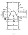
- Figure 6 shows one of the plurality of nozzles 250 disposed in the conduit 255 of the dirt collection conduit system 220 as a first arrangement for producing a low pressure regime in the conduit 255 of the dirt collection conduit system 220.
- the nozzle 250 is arranged inside the conduit 255 of the dirt collection conduit system 220.
- the nozzle 250 is disposed in the conduit 255 such that it is adjacent to where the suction chamber 205 opens into the conduit 255, such that the low pressure regime created near the mouth of the nozzle 250 serves to enhance the suction inside the suction chamber 205.
- the nozzle 250 comprises concentrically placed boreholes 305, 310 and 315. Outer diameter b2 of the nozzle 250 fits inside the inner diameter c of the conduit 255.
- the distance between the boreholes 305 and 310 is al and this forms a first portion 306 of the nozzle 250 with a constant diameter.
- the length of the nozzle 250 between the boreholes 310 and 315 is converged such that the diameter of the borehole 315 is lesser than the diameter of the borehole 305 and 310.
- This converging portion forms a second portion 307 of the nozzle 250.
- the angle of convergence is ⁇ .
- the angle of convergence ⁇ can be any angle between 30° and 50°.
- the distance between the boreholes 310 and 315 is a2.
- the inner diameter of the nozzle 250 at the borehole 310 is bl and the inner diameter of the nozzle 250 at the borehole 315 is d.
- the mouth of the nozzle 250 is at the borehole 315.
- Figure 7 shows the working of the nozzle 250 described in Figure 6 .
- Liquid flowing through the conduit 255 enters the borehole 305 and travels through the borehole 310 and finally through the borehole 315 where it converges.
- a low pressure regime 320 in the conduit 255 is created in the proximity to the borehole 315 of the nozzle 250.
- This low pressure regime 320 in the dirt collection conduit system 220 along with a higher pressure on the outer surface 145 of the filter screen 105 creates a pressure differential which makes the fluid rush through the central nozzle 225 inside the suction chamber 205, which subsequently results in removal of retentate through the plurality of peripheral suction nozzles 235.
- Figure 8 shows an orifice plate 325 in the conduit 255 of the dirt collection conduit system 220 which is a second arrangement for producing a low pressure regime in the conduit 255 of the dirt collection conduit system 220.
- Figure 9 shows a schematic of the working of the orifice plate shown in Figure 8 .
- the orifice plate 325 has a thickness tl is disposed or positioned inside the conduit 255 of the dirt collection conduit system 220, such that a low pressure regime 330 produced near a mouth of the orifice plate is adjacent the opening of the suction chamber 205 into the conduit 255.
- the orifice plate comprises a first borehole 335 and a second borehole 340, the first borehole 335 being larger than the second borehole 340.
- the bore of the orifice plate 325 converges from the first borehole 335 towards the second borehole 340.
- the fluid passing through the converging portion causes the low pressure regime 330 due to Bernoulli's principle.
- the first borehole 335 and the second borehole 340 are concentric and the converging angle between them is ⁇ .
- ⁇ can be any value between 1° and 10°.
- e is the diameter of the second borehole 340
- fl is the diameter of the first borehole 335
- f2 is the outer diameter of the orifice plate 325
- c is the inner diameter of the conduit 255.
Description
- This invention generally relates to a cleaning apparatus for cleaning filter screens and specifically to cleaning apparatus for cleaning filter screens having nozzles for creating suction. This invention finds particular, but not exclusive, application in industries employing filter screens for filtering purposes.
- Many hydraulic equipments involve the use of filter screens for filtering water that is used in the hydraulic equipments. The water that is used can be contaminated, so that the contaminants are retained at the filters and the accumulation of the contaminants results in the formation of retentate. Retentate slows down the flow of water and increases the differential pressure. Dust extraction assemblies for removing contamination are constructed of a plurality of nozzles at pre-defined distances from the surface of filter element. Such nozzles are connected to collector pipe which moves with the help of hydraulics or electric motors. A purge valve is connected to the dust collector pipe which opens to the atmosphere. Cleaning of the filter screen is done automatically either on the basis of differential pressure between filter housing and pressure at the purge valve outlet (atmospheric pressure) or it can be done according to preset time interval. During the cleaning process, the purge valve opens and fluid enters into the plurality of nozzles which are in close proximity to the filter screen. Depending on differential pressure, debris/retentate deposited on the element surface is pulled out through nozzles and finally discharged from filter housing through the flushing line. One of the prior arts
WO2014027715A1 relates to a multicage-type apparatus for filtering ballast water in which a plurality of filtering units are packetized and connected inside a body from which ballast water is introduced or discharged, and to a method for same, and more specifically, to a multicage-type apparatus for filtering ballast water for automatically controlling simultaneous reverse-washing. Another prior artUS20120223028A1 discloses a suction nozzle assembly, comprising a tube coupled to a pressure sink at a distal side thereof, a nozzle, a resilient element which couples said nozzle to a proximal side of said tube and a deformable housing which bridges a gap between said proximal side of said tube and said nozzle. Optionally, a pressure equalizer, for example, a through aperture, is formed in said nozzle. - The disadvantage with the above described self-cleaning mechanism is the reduction of the cleaning efficiency and effectiveness.
-
- 1. It is the primary objective of the invention to provide an apparatus for efficient cleaning of filters with increased suction force
- 2. It is another objective of the invention to provide an apparatus for utilizing a low volume of liquid for cleaning as cleaning can be performed at low pressure
- The invention is defined in the appended claims.
- According to an aspect of an invention, a cleaning apparatus for cleaning filter screen is disclosed, comprising a suction chamber movably positioned adjacent a filter screen to be cleaned such that a first end of the suction chamber is positioned adjacent an inner surface of the filter screen and a second end of the suction chamber being coupled to a dirt collection conduit system for fluid communication with the dirt collection system. The outer surface of the filter screen is arranged to be at a higher pressure than the dirt collection conduit system such that a pressure differential is arranged to be maintained between the outer surface of the filter screen and the dirt collection conduit system through the suction chamber. The suction chamber further comprises a nozzle at the first end, wherein a largest diameter of the nozzle is lesser than an inner diameter of the suction chamber, the nozzle and the suction chamber arranged concentrically. The suction chamber further comprises a circular clearance between the largest diameter of the nozzle and the inner diameter of the suction chamber. The pressure differential is arranged to facilitate movement of fluid from the outer surface of the filter screen to the dirt collection conduit system and wherein the fluid movement through the nozzle of the suction chamber creates a low pressure regime around a mouth of the nozzle inside the suction chamber, thereby facilitating fluid from the outer surface of the filter screen to rush towards the low pressure regime through the circular clearance, thus removing retentate forcefully from the inner surface of the filter screen.
-
-
Figure 1 shows a screen filtering system with a cleaning apparatus for cleaning the filter screen in the screen filtering system -
Figure 2 shows a first embodiment of the cleaning apparatus -
Figure 3 shows a divergent nozzle disposed in the suction chamber of the first embodiment of the cleaning apparatus -
Figure 4 shows a second embodiment of the cleaning apparatus -
Figure 5a shows a front elevational view of an orifice plate -
Figure 5b shows a longitudinal sectional view along section A-A of the orifice plate shown inFigure 5a -
Figure 6 shows a first arrangement of a nozzle in the conduit of the dirt collection conduit system -
Figure 7 shows a schematic of the working of the nozzle shown inFigure 6 -
Figure 8 shows a second arrangement of an orifice plate in the conduit of the dirt collection conduit system -
Figure 9 shows a schematic of the working of the orifice plate shown inFigure 8 -
Figure 1 shows ascreen filtering system 100 with acleaning apparatus 200 for cleaning thefilter screen 105 in thescreen filtering system 100. Thescreen filtering system 100 comprises ahousing 110 which is circular in profile. Thescreen filter 105 is fitted by way of suitable fastening arrangements to thehousing 110 internally, the fastening arrangements being water proof. For the purposes of visualization, thehousing 110 and thefilter screen 105 are concentric cylinders with thefilter screen 105 arranged internally to thehousing 110. Thescreen filtering system 100 further comprises aninlet pipe 115 which opens into achamber 120 internal to thefilter screen 105. The water that is pressurized passes through thefilter screen 105 into the circular clearance orinterval 125 between thefilter screen 105 and thehousing 110 and exist through anexit pipe 130 which is controlled by avalve 135. In the process of water or any other fluid flowing in this way, the contaminants in the fluid get accumulated on aninner surface 140 of thefilter screen 105. The accumulated contaminants form as retentate on the inner orinternal surface 140 of thefilter screen 105. -
Figure 2 shows a first embodiment of thecleaning apparatus 200. Thecleaning apparatus 200 comprises asuction chamber 205, which is a cylindrical element of constant diameter that is movably positioned adjacent thefilter screen 105 to be cleaned. Thesuction chamber 205 is positioned in such a way that it is orthogonal to thefilter screen 105. Thesuction chamber 205 comprises a first end 210 adjacent theinner surface 140 of thefilter screen 105 and a second end 215 of thesuction chamber 205 coupled to a dirtcollection conduit system 220. The dirtcollection conduit system 220 extends along an axis 110' of thehousing 110. Thesuction chamber 205 extends from the dirtcollection conduit system 220 to theinner surface 140 of the filter screen. Thesuction chamber 205 is orthogonal to the axis 110' as well. Thesuction chamber 205 is coupled to the dirtcollection conduit system 220 such that there is fluid communication between thesuction chamber 205 and the dirtcollection conduit system 220. The filter screen comprises an outer orexternal surface 145 which is arranged to be at atmospheric pressure or a pressure higher than that when thecleaning apparatus 200 is being used. The dirtcollection conduit system 220 extends along the axis 110' of thehousing 110 and opens out externally through apurge outlet 150 and a purging valve 155. Thepurge outlet 150 is connected to a low pressure environment when thecleaning apparatus 200 is being used. Thus, when thecleaning apparatus 200 is being used, there is maintained a pressure differential between the outer surface orexternal surface 145 and the dirtcollection conduit system 220. - The
suction chamber 205 further comprises acentral nozzle 225 attached to the first end 210 of thesuction chamber 205. Thecentral nozzle 225 is such that a largest diameter of thecentral nozzle 225 is lesser than an inner diameter of thesuction chamber 205. Thecentral nozzle 225 and thesuction chamber 205 are arranged concentrically. Between the largest diameter of thecentral nozzle 225 and the inner diameter of thesuction chamber 205 is acircular clearance 230 in which is circularly arranged a plurality ofperipheral suction nozzles 235. Thecleaning apparatus 200 is activated by initiating and maintaining a pressure differential between theouter surface 145 of thefilter screen 105 and the dirtcollection conduit system 220. This pressure differential causes movement of fluid from theouter surface 145 of thefilter screen 105 to the dirtcollection conduit system 220 through thesuction chamber 205. When the fluid moves through thecentral nozzle 225 of thesuction chamber 205, alow pressure regime 240 is created around and in proximity to a mouth 245 of thecentral nozzle 225 inside thesuction chamber 205. Thislow pressure regime 240 acts as a suction force to suck or pull fluid from theouter surface 145 of thefilter screen 105 to rush towards thelow pressure regime 240, such that the retentate accumulated in theinner surface 140 of thefilter screen 105 is forcefully removed. The low pressure regime is formed due to increased velocity which is due to the convergence in the section of thenozzle 225. The pressure differential due to thelow pressure regime 240 created is more than the pressure differential between theouter surface 145 of thefilter screen 105 and thepurge outlet 150 through the dirtcollection conduit system 220. - As illustrated in
Figure 1 , thesuction chamber 205 is arranged to rotate about an axis 110' of the dirtcollection conduit system 220. The axis 110' of the dirtcollection conduit system 220 is the same as the axis 110' of thehousing 110, as the dirtcollection conduit system 220 extends along the axis 110' of thehousing 110. The rotation of thesuction chamber 205 is meant to remove the retentate from a circular portion of thecylindrical filter screen 105. Hence, one complete rotation of thesuction chamber 205 about the axis 110' of the dirtcollection conduit system 220 when thecleaning apparatus 200 is functioning, results in the removal of retentate circularly from thefilter screen 105. - The
cleaning apparatus 200 further comprises a plurality ofsuction chambers 205 coupled rotatably to the dirtcollection conduit system 220 at different positions along the axis 110' of the dirtcollection conduit system 220. The number ofrotatable suction chambers 205 can vary anywhere from 2 to 5 or more depending on the length of thefilter screen 105 inside thehousing 110. The advantage of having a plurality ofsuction chambers 205 is to cover the entire surface area of thefilter screen 105. The rotation of thesuction chambers 205 is achieved by hydraulic or electric rotating techniques, which is understood by a person skilled in the art. The principle of working of the plurality ofsuction chambers 205 are the same as described above. - The dirt
collection conduit system 220 further comprises a plurality ofnozzles 250 arranged inside a conduit 255 of the dirtcollection conduit system 220, such that the number ofnozzles 250 is the same as the number ofsuction chambers 205. One nozzle among the plurality ofnozzles 250 is associated with one suction chamber within the plurality ofsuction chambers 205. Each nozzle among the plurality ofnozzles 250 creates a low pressure regime near the mouth of the nozzle which enhances or adds up the suction force inside thesuction chambers 205 triggered by the existence of the pressure differential between theouter surface 145 of thefilter screen 105 and the dirtcollection conduit system 220. This is described in detail hereinafter. - As illustrated in
Figure 2 , thecentral nozzle 225 comprises a first portion 260 with a constant cross sectional area and asecond portion 265 with a converging cross sectional area. The first portion 260 is proximal and adjacent to the first end 210 of thesuction chamber 205 and thesecond portion 265 is distal to the first end 210 of thesuction chamber 205.Figure 3 shows adivergent cone 270 disposed in thesuction chamber 205 of the first embodiment of thecleaning apparatus 200. Thesuction chamber 205 can additionally comprise adivergent cone 270 extending from an opening or mouth of thesecond portion 265 to the second end 215 of thesuction chamber 205 leaving a gap around 265.Divergent cone 270 facilitates streamlining of fluid ejected from thesecond portion 265 of thenozzle 225. In the presence of thedivergent nozzle 270, thelow pressure regime 240 is generated inside thedivergent nozzle 270 near the mouth of thesecond portion 265. The angle of thesecond portion 265 is α and the angle of thedivergent cone 270 is β. The optimum values for α and β can be 30° to 50° and 1° to 10° respectively. -
Figure 4 shows a second embodiment of thecleaning apparatus 200. In this embodiment, thecentral nozzle 225 comprises a convergingportion 275. The second embodiment of thecleaning apparatus 200 is easy to manufacture resulting in lesser cost of manufacture. Near the mouth of thecentral nozzle 225 is created thelow pressure regime 240. There is acircular clearance 230 as described above between thecentral nozzle 225 and thesuction chamber 205. Thecentral nozzle 225 and thesuction chamber 205 are arranged coaxially. Thecircular clearance 230 comprises a plurality ofperipheral suction nozzles 235 arranged circularly in thecircular clearance 230. Thelow pressure regime 240 enables fluid to be sucked in forcefully through the plurality ofsuction nozzles 235, so as to remove the retentate from theinner surface 140 of thefilter screen 105. Thecentral nozzle 225 and thenozzles 250 of the dirt collection conduit system work on the principle of venturi in producing a low pressure regime and associated suction. Thecentral nozzle 225 in all the embodiments mentioned can be circular, elliptical, rectangular or any other polygonal shape. The second embodiment as mentioned above can be achieved with the help of an orifice plate as illustrated inFigures 5a and5b .Figure 5a shows a front elevational view of anorifice plate 280.Figure 5b shows a longitudinal sectional view along section A-A of theorifice plate 280 shown inFigure 5a . The construction or structural arrangement of the second embodiment is mentioned below. Thesuction chamber 205 is fitted with theorifice plate 280 at the first end 210 such that theorifice plate 280 fits over thecentral nozzle 225. Theorifice plate 280 has abore 285 which fits over thecentral nozzle 225 of thesuction chamber 205. Thebore 285 comprises a principalcircular bore 290 and a secondarycircular bore 295. The principalcircular bore 290 and the secondarycircular bore 295 are coaxial and matches with the dimensions of thecentral nozzle 225 to provide a good fit for theorifice plate 280 over thecentral nozzle 225. The orifice plate comprises a plurality ofholes 296 in the periphery and surrounding thebore 285 to form the plurality ofperipheral suction nozzles 235. - The external surface of the
suction chamber 205 can be circular, elliptical or any polygonal shape. The internal surface and cavity of thesuction chamber 205 is cylindrical. For an externally elliptically shapedsuction chamber 205, it is arranged in thehousing 100 in such a way that the major axis makes an angle θ with a horizontal plane. Thesuction chamber 205 is arranged such that the slope of travel path of thesuction chamber 205 matches θ. The advantage of this arrangement is to minimize the drag force acting on thesuction chamber 205 and make thecleaning apparatus 200 more efficient. -
Figure 6 shows one of the plurality ofnozzles 250 disposed in the conduit 255 of the dirtcollection conduit system 220 as a first arrangement for producing a low pressure regime in the conduit 255 of the dirtcollection conduit system 220. As illustrated inFigure 6 , thenozzle 250 is arranged inside the conduit 255 of the dirtcollection conduit system 220. Thenozzle 250 is disposed in the conduit 255 such that it is adjacent to where thesuction chamber 205 opens into the conduit 255, such that the low pressure regime created near the mouth of thenozzle 250 serves to enhance the suction inside thesuction chamber 205. Thenozzle 250 comprises concentrically placedboreholes nozzle 250 fits inside the inner diameter c of the conduit 255. The distance between theboreholes first portion 306 of thenozzle 250 with a constant diameter. The length of thenozzle 250 between theboreholes borehole 315 is lesser than the diameter of theborehole second portion 307 of thenozzle 250. The angle of convergence is Φ. The angle of convergence Φ can be any angle between 30° and 50°. The distance between theboreholes nozzle 250 at theborehole 310 is bl and the inner diameter of thenozzle 250 at theborehole 315 is d. The mouth of thenozzle 250 is at theborehole 315. -
Figure 7 shows the working of thenozzle 250 described inFigure 6 . Liquid flowing through the conduit 255 enters theborehole 305 and travels through theborehole 310 and finally through the borehole 315 where it converges. According to Bernoulli's principle, a low pressure regime 320 in the conduit 255 is created in the proximity to theborehole 315 of thenozzle 250. This low pressure regime 320 in the dirtcollection conduit system 220 along with a higher pressure on theouter surface 145 of thefilter screen 105 creates a pressure differential which makes the fluid rush through thecentral nozzle 225 inside thesuction chamber 205, which subsequently results in removal of retentate through the plurality ofperipheral suction nozzles 235. -
Figure 8 shows an orifice plate 325 in the conduit 255 of the dirtcollection conduit system 220 which is a second arrangement for producing a low pressure regime in the conduit 255 of the dirtcollection conduit system 220.Figure 9 shows a schematic of the working of the orifice plate shown inFigure 8 . The orifice plate 325 has a thickness tl is disposed or positioned inside the conduit 255 of the dirtcollection conduit system 220, such that alow pressure regime 330 produced near a mouth of the orifice plate is adjacent the opening of thesuction chamber 205 into the conduit 255. The orifice plate comprises afirst borehole 335 and asecond borehole 340, thefirst borehole 335 being larger than thesecond borehole 340. In other words, the bore of the orifice plate 325 converges from thefirst borehole 335 towards thesecond borehole 340. The fluid passing through the converging portion causes thelow pressure regime 330 due to Bernoulli's principle. Thefirst borehole 335 and thesecond borehole 340 are concentric and the converging angle between them is Ψ. Ψ can be any value between 1° and 10°. InFigure 8 , e is the diameter of thesecond borehole 340, fl is the diameter of thefirst borehole 335, f2 is the outer diameter of the orifice plate 325 and c is the inner diameter of the conduit 255. - It is to be understood that the foregoing description is intended to be purely illustrative of the principles of the disclosed techniques, rather than exhaustive thereof, and that the present invention is not intended to be limited other than as expressly set forth in the following claims.
Claims (10)
- A cleaning apparatus for cleaning filter screen, comprising:a suction chamber (205) movably positioned adjacent a filter screen (105) to be cleaned such that a first end (210) of the suction chamber (205) is positioned adjacent an inner surface (140) of the filter screen (105) and a second end (215) of the suction chamber (205) being coupled to a dirt collection conduit system (220) for fluid communication with the dirt collection system (220), wherein an outer surface (145) of the filter screen (105) is arranged to be at a higher pressure than the dirt collection conduit system (220) such that a pressure differential is arranged to be maintained between the outer surface (145) of the filter screen (105) and the dirt collection conduit system (220) through the suction chamber (205);whereinthe suction chamber (205) comprises a central nozzle (225) at the first end (210), characterized in that the central nozzle (225) comprises a first portion (260) with a constant cross sectional area and a second portion (265) with a converging cross sectional area, wherein the first portion (260) is proximal and adjacent to the first end (210) of the suction chamber (205) and the second portion (265) is distal to the first end (210) of the suction chamber (205), wherein a largest diameter of the central nozzle is lesser than an inner diameter of the suction chamber (205), the central nozzle (225) and the suction chamber (205) are arranged concentrically; andthe suction chamber (205) further comprises a plurality of peripheral suction nozzles (235) arranged circularly in a circular clearance between the largest diameter of the nozzle and the inner diameter of the suction chamber (205),wherein a pressure differential between outer surface (145) of the filter screen (105) and the dirt collection conduit system (220) facilitates movement of fluid from the outer surface (145) of the filter screen (105) to the dirt collection conduit system (220) and wherein the fluid movement through the central nozzle (225) of the suction chamber (205) creates a low pressure regime around a mouth of the central nozzle (225) inside the suction chamber (205), that facilitates fluid flow from the outer surface (145) of the filter screen (105) to rush towards the low pressure regime through the plurality of peripheral suction nozzles (235), thus removing retentate forcefully from the inner surface of the filter screen.
- The cleaning apparatus for cleaning filter screen as claimed in claim 1, wherein the suction chamber (205) is arranged to rotate about an axis of the dirt collection conduit system (220), wherein the dirt collection conduit system (220) extends along an axis of a cylindrical housing (110), the cylindrical housing (110) containing the cylindrical filter screen internally and wherein the rotation of the suction chamber is arranged to facilitate removing retentate from a circular portion of the cylindrical filter screen.
- The cleaning apparatus for cleaning filter screen as claimed in claim 2, further comprising a purge outlet (150) and a purging valve (155), arranged for connecting the dirt collection conduit system (220) to a low-pressure environment.
- The cleaning apparatus for cleaning filter screen as claimed in claim 3, further comprising a plurality of suction chambers (205) rotatably coupled to the dirt collection conduit system (220) with fluid communication between the plurality of suction chambers (205) and the dirt collection conduit system (220), the plurality of suction chambers (205) arranged at different positions along the dirt collection conduit system to facilitate removing retentate from different positions of cylindrical filter screen.
- The cleaning apparatus for cleaning filter screen as claimed in claim 4, wherein the dirt collection conduit system further comprises a plurality of nozzles (235) arranged inside a conduit of the dirt collection conduit system (220), each of the plurality of nozzles (235) associated with each of the plurality of suction chambers (205), such that each of the plurality of nozzles is arranged to produce a low pressure regime to facilitate suction from each of the suction chambers when the pressure differential exists between the outer surface of the filter screen and the dirt collection conduit system.
- The cleaning apparatus for cleaning filter screen as claimed in claim 5, wherein each of the nozzles within the plurality of nozzles comprises a first portion (260) with a constant diameter and a second portion (265) with a convergence leading to a mouth of the nozzle.
- The cleaning apparatus for cleaning filter screen as claimed in claim 5, wherein each of the nozzles within the plurality of nozzles (235) comprises a first borehole (335) with a larger diameter and a second borehole (340) with a lesser diameter.
- The cleaning apparatus for cleaning filter screen as claimed in claim 1, wherein the central nozzle comprises a first portion (306) with a constant cross-sectional area and a second portion (307) with a converging cross-sectional area, wherein the first portion (260) is proximal to the first end of the suction chamber (205) and the second portion (265) is distal to the first end of the suction chamber.
- The cleaning apparatus for cleaning filter screen as claimed in claim 8, further comprising a divergent nozzle (270) extending from an opening of the second portion to the second end of the suction chamber to facilitate streamlining of the fluid ejected from the second portion of the nozzle.
- The cleaning apparatus for cleaning filter screen as claimed in claim 4, wherein each of the plurality of suction chambers (205) is shaped elliptical externally, such that a major axis of the suction chamber forms an angle θ with a horizontal plane, wherein the angle θ is the same as an angle of spiral movement of the nozzle to minimize drag.
Applications Claiming Priority (2)
| Application Number | Priority Date | Filing Date | Title |
|---|---|---|---|
| IN2174MU2014 | 2015-01-04 | ||
| PCT/IN2016/000003 WO2016108253A2 (en) | 2015-01-04 | 2016-01-04 | A cleaning apparatus for cleaning filter screens |
Publications (3)
| Publication Number | Publication Date |
|---|---|
| EP3240462A2 EP3240462A2 (en) | 2017-11-08 |
| EP3240462A4 EP3240462A4 (en) | 2018-12-05 |
| EP3240462B1 true EP3240462B1 (en) | 2021-09-22 |
Family
ID=56285113
Family Applications (1)
| Application Number | Title | Priority Date | Filing Date |
|---|---|---|---|
| EP16732887.1A Active EP3240462B1 (en) | 2015-01-04 | 2016-01-04 | A cleaning apparatus for cleaning filter screens |
Country Status (5)
| Country | Link |
|---|---|
| US (1) | US10688418B2 (en) |
| EP (1) | EP3240462B1 (en) |
| ES (1) | ES2900754T3 (en) |
| IL (1) | IL252706B (en) |
| WO (1) | WO2016108253A2 (en) |
Families Citing this family (1)
| Publication number | Priority date | Publication date | Assignee | Title |
|---|---|---|---|---|
| CN115177993A (en) * | 2022-06-07 | 2022-10-14 | 南通市华业石油机械有限公司 | Scale prevention and corrosion prevention magnetic ring stainless steel sieve tube |
Family Cites Families (12)
| Publication number | Priority date | Publication date | Assignee | Title |
|---|---|---|---|---|
| US523581A (en) | 1894-07-24 | Alexander klinger | ||
| IL71999A0 (en) * | 1984-06-04 | 1984-10-31 | Filtration Water Filters For A | Fluid filter system and suction nozzle therefor |
| US5268006A (en) * | 1989-03-15 | 1993-12-07 | Matsushita Electric Industrial Co., Ltd. | Ceramic capacitor with a grain boundary-insulated structure |
| US5228993A (en) * | 1990-02-09 | 1993-07-20 | Mordeki Drori | Cleanable filter system with longitudinally movable and rotatable cleaning member |
| US5322222A (en) * | 1992-10-05 | 1994-06-21 | Lott W Gerald | Spiral jet fluid mixer |
| US6267879B1 (en) * | 1999-08-11 | 2001-07-31 | Odis Irrigation Equipment Ltd. | Continuous liquid filtering apparatus with multi-layer sintered filtering element |
| US6447617B1 (en) | 2000-03-17 | 2002-09-10 | Aqua-Aerobic Systems, Inc. | High efficiency cleaning of rotating filter media |
| AU2003227270A1 (en) * | 2002-04-04 | 2003-10-20 | Kabushiki Kaisha Yms | Dust collector |
| EP2498924A2 (en) * | 2009-11-12 | 2012-09-19 | Filter Safe Ltd. | Filter proximity nozzle |
| SG190715A1 (en) * | 2010-12-02 | 2013-07-31 | Amiad Water Systems Ltd | Self cleaning filter system |
| KR101394227B1 (en) * | 2012-08-17 | 2014-05-27 | 주식회사 파나시아 | Multi―cage type ballast water filter equipment auto―controlling simultaneously back―washing and method thereof |
| CN103611343B (en) * | 2013-12-10 | 2015-07-22 | 武汉市汉江石油物资技术开发有限责任公司 | Backwash spray nozzle for granular filter material filter device |
-
2016
- 2016-01-04 WO PCT/IN2016/000003 patent/WO2016108253A2/en active Application Filing
- 2016-01-04 ES ES16732887T patent/ES2900754T3/en active Active
- 2016-01-04 US US15/536,740 patent/US10688418B2/en active Active
- 2016-01-04 EP EP16732887.1A patent/EP3240462B1/en active Active
-
2017
- 2017-06-06 IL IL252706A patent/IL252706B/en unknown
Also Published As
| Publication number | Publication date |
|---|---|
| IL252706B (en) | 2021-12-01 |
| ES2900754T3 (en) | 2022-03-18 |
| WO2016108253A2 (en) | 2016-07-07 |
| WO2016108253A3 (en) | 2016-10-06 |
| EP3240462A2 (en) | 2017-11-08 |
| EP3240462A4 (en) | 2018-12-05 |
| US10688418B2 (en) | 2020-06-23 |
| US20190091612A1 (en) | 2019-03-28 |
| IL252706A0 (en) | 2017-08-31 |
Similar Documents
| Publication | Publication Date | Title |
|---|---|---|
| CN105916424B (en) | Vacuum cleaner head | |
| DE69909117T2 (en) | Cyclonic separation | |
| US9038736B2 (en) | Wellbore filter screen and related methods of use | |
| EP2905062A1 (en) | Exhaust gas processing apparatus | |
| JP6758518B2 (en) | Large diameter long bag filter dust remover | |
| EP2042071A1 (en) | Cyclone silencer of cleaner and dust removing device having the same | |
| JP2014018702A (en) | Device for executing work while moving in pipe | |
| EP3240462B1 (en) | A cleaning apparatus for cleaning filter screens | |
| CN110185488A (en) | A kind of dust-removing blower for mine | |
| CN105750098B (en) | A kind of cyclone separator | |
| JP6715238B2 (en) | Separation device for dust and other pollutants | |
| KR101643574B1 (en) | Jet nozzle for bagfilter cleaning | |
| US20220199380A1 (en) | High efficiency trap for particle collection in a vacuum foreline | |
| US5179830A (en) | Apparatus for cleaning stranded cable | |
| TWI558462B (en) | Tornado filter | |
| CN109091986B (en) | Air purifier | |
| DE102004030350A1 (en) | Vacuum cleaner, has liquid precipitator with cyclone having inlet, outlet and discharge unit, where air is supplied across inlet to cyclone and released across outlet, and precipitated liquid is guided back across unit into filling space | |
| KR101102453B1 (en) | Nozzle for cleaning a filter bag in dust collector | |
| US9995114B2 (en) | High efficiency nozzle | |
| KR101360169B1 (en) | Venturi Nozzle and A Filter Structure with Venturi Nozzle in Dust Collector | |
| CN209959282U (en) | Mining dust exhausting fan | |
| TWI833970B (en) | High efficiency trap for particle collection in a vacuum foreline | |
| RU195672U1 (en) | DIRECT CYCLON | |
| CN202762179U (en) | High-pressure back flush filter | |
| DE102017220701A1 (en) | Centrifugal separator with centric feed of the air to be cleaned |
Legal Events
| Date | Code | Title | Description |
|---|---|---|---|
| STAA | Information on the status of an ep patent application or granted ep patent |
Free format text: STATUS: THE INTERNATIONAL PUBLICATION HAS BEEN MADE |
|
| PUAI | Public reference made under article 153(3) epc to a published international application that has entered the european phase |
Free format text: ORIGINAL CODE: 0009012 |
|
| STAA | Information on the status of an ep patent application or granted ep patent |
Free format text: STATUS: REQUEST FOR EXAMINATION WAS MADE |
|
| 17P | Request for examination filed |
Effective date: 20170724 |
|
| AK | Designated contracting states |
Kind code of ref document: A2 Designated state(s): AL AT BE BG CH CY CZ DE DK EE ES FI FR GB GR HR HU IE IS IT LI LT LU LV MC MK MT NL NO PL PT RO RS SE SI SK SM TR |
|
| AX | Request for extension of the european patent |
Extension state: BA ME |
|
| DAV | Request for validation of the european patent (deleted) | ||
| DAX | Request for extension of the european patent (deleted) | ||
| A4 | Supplementary search report drawn up and despatched |
Effective date: 20181029 |
|
| RIC1 | Information provided on ipc code assigned before grant |
Ipc: B01D 29/11 20060101ALI20181023BHEP Ipc: B01D 46/04 20060101ALI20181023BHEP Ipc: A47L 5/12 20060101AFI20181023BHEP Ipc: A47L 9/10 20060101ALI20181023BHEP Ipc: A47L 9/20 20060101ALI20181023BHEP Ipc: A47L 5/36 20060101ALI20181023BHEP Ipc: B01D 46/24 20060101ALI20181023BHEP |
|
| STAA | Information on the status of an ep patent application or granted ep patent |
Free format text: STATUS: EXAMINATION IS IN PROGRESS |
|
| 17Q | First examination report despatched |
Effective date: 20200414 |
|
| STAA | Information on the status of an ep patent application or granted ep patent |
Free format text: STATUS: EXAMINATION IS IN PROGRESS |
|
| GRAP | Despatch of communication of intention to grant a patent |
Free format text: ORIGINAL CODE: EPIDOSNIGR1 |
|
| STAA | Information on the status of an ep patent application or granted ep patent |
Free format text: STATUS: GRANT OF PATENT IS INTENDED |
|
| INTG | Intention to grant announced |
Effective date: 20210514 |
|
| GRAJ | Information related to disapproval of communication of intention to grant by the applicant or resumption of examination proceedings by the epo deleted |
Free format text: ORIGINAL CODE: EPIDOSDIGR1 |
|
| STAA | Information on the status of an ep patent application or granted ep patent |
Free format text: STATUS: EXAMINATION IS IN PROGRESS |
|
| GRAS | Grant fee paid |
Free format text: ORIGINAL CODE: EPIDOSNIGR3 |
|
| STAA | Information on the status of an ep patent application or granted ep patent |
Free format text: STATUS: GRANT OF PATENT IS INTENDED |
|
| GRAP | Despatch of communication of intention to grant a patent |
Free format text: ORIGINAL CODE: EPIDOSNIGR1 |
|
| INTC | Intention to grant announced (deleted) | ||
| GRAA | (expected) grant |
Free format text: ORIGINAL CODE: 0009210 |
|
| STAA | Information on the status of an ep patent application or granted ep patent |
Free format text: STATUS: THE PATENT HAS BEEN GRANTED |
|
| INTG | Intention to grant announced |
Effective date: 20210727 |
|
| RIN1 | Information on inventor provided before grant (corrected) |
Inventor name: JAIN, AJIT BHAVARLAL Inventor name: JOSHI, ABHIJIT BHASKAR |
|
| AK | Designated contracting states |
Kind code of ref document: B1 Designated state(s): AL AT BE BG CH CY CZ DE DK EE ES FI FR GB GR HR HU IE IS IT LI LT LU LV MC MK MT NL NO PL PT RO RS SE SI SK SM TR |
|
| REG | Reference to a national code |
Ref country code: GB Ref legal event code: FG4D |
|
| REG | Reference to a national code |
Ref country code: DE Ref legal event code: R096 Ref document number: 602016064008 Country of ref document: DE |
|
| REG | Reference to a national code |
Ref country code: IE Ref legal event code: FG4D |
|
| REG | Reference to a national code |
Ref country code: CH Ref legal event code: EP Ref country code: AT Ref legal event code: REF Ref document number: 1431642 Country of ref document: AT Kind code of ref document: T Effective date: 20211015 |
|
| REG | Reference to a national code |
Ref country code: LT Ref legal event code: MG9D |
|
| REG | Reference to a national code |
Ref country code: NL Ref legal event code: MP Effective date: 20210922 |
|
| PG25 | Lapsed in a contracting state [announced via postgrant information from national office to epo] |
Ref country code: LT Free format text: LAPSE BECAUSE OF FAILURE TO SUBMIT A TRANSLATION OF THE DESCRIPTION OR TO PAY THE FEE WITHIN THE PRESCRIBED TIME-LIMIT Effective date: 20210922 Ref country code: BG Free format text: LAPSE BECAUSE OF FAILURE TO SUBMIT A TRANSLATION OF THE DESCRIPTION OR TO PAY THE FEE WITHIN THE PRESCRIBED TIME-LIMIT Effective date: 20211222 Ref country code: NO Free format text: LAPSE BECAUSE OF FAILURE TO SUBMIT A TRANSLATION OF THE DESCRIPTION OR TO PAY THE FEE WITHIN THE PRESCRIBED TIME-LIMIT Effective date: 20211222 Ref country code: HR Free format text: LAPSE BECAUSE OF FAILURE TO SUBMIT A TRANSLATION OF THE DESCRIPTION OR TO PAY THE FEE WITHIN THE PRESCRIBED TIME-LIMIT Effective date: 20210922 Ref country code: FI Free format text: LAPSE BECAUSE OF FAILURE TO SUBMIT A TRANSLATION OF THE DESCRIPTION OR TO PAY THE FEE WITHIN THE PRESCRIBED TIME-LIMIT Effective date: 20210922 Ref country code: RS Free format text: LAPSE BECAUSE OF FAILURE TO SUBMIT A TRANSLATION OF THE DESCRIPTION OR TO PAY THE FEE WITHIN THE PRESCRIBED TIME-LIMIT Effective date: 20210922 Ref country code: SE Free format text: LAPSE BECAUSE OF FAILURE TO SUBMIT A TRANSLATION OF THE DESCRIPTION OR TO PAY THE FEE WITHIN THE PRESCRIBED TIME-LIMIT Effective date: 20210922 |
|
| PGFP | Annual fee paid to national office [announced via postgrant information from national office to epo] |
Ref country code: FR Payment date: 20211217 Year of fee payment: 7 |
|
| REG | Reference to a national code |
Ref country code: GR Ref legal event code: EP Ref document number: 20210403369 Country of ref document: GR Effective date: 20220113 |
|
| REG | Reference to a national code |
Ref country code: AT Ref legal event code: MK05 Ref document number: 1431642 Country of ref document: AT Kind code of ref document: T Effective date: 20210922 |
|
| PG25 | Lapsed in a contracting state [announced via postgrant information from national office to epo] |
Ref country code: LV Free format text: LAPSE BECAUSE OF FAILURE TO SUBMIT A TRANSLATION OF THE DESCRIPTION OR TO PAY THE FEE WITHIN THE PRESCRIBED TIME-LIMIT Effective date: 20210922 |
|
| PGFP | Annual fee paid to national office [announced via postgrant information from national office to epo] |
Ref country code: GR Payment date: 20211227 Year of fee payment: 7 |
|
| REG | Reference to a national code |
Ref country code: ES Ref legal event code: FG2A Ref document number: 2900754 Country of ref document: ES Kind code of ref document: T3 Effective date: 20220318 |
|
| PG25 | Lapsed in a contracting state [announced via postgrant information from national office to epo] |
Ref country code: AT Free format text: LAPSE BECAUSE OF FAILURE TO SUBMIT A TRANSLATION OF THE DESCRIPTION OR TO PAY THE FEE WITHIN THE PRESCRIBED TIME-LIMIT Effective date: 20210922 |
|
| PGFP | Annual fee paid to national office [announced via postgrant information from national office to epo] |
Ref country code: DE Payment date: 20220120 Year of fee payment: 7 |
|
| PG25 | Lapsed in a contracting state [announced via postgrant information from national office to epo] |
Ref country code: IS Free format text: LAPSE BECAUSE OF FAILURE TO SUBMIT A TRANSLATION OF THE DESCRIPTION OR TO PAY THE FEE WITHIN THE PRESCRIBED TIME-LIMIT Effective date: 20220122 Ref country code: SK Free format text: LAPSE BECAUSE OF FAILURE TO SUBMIT A TRANSLATION OF THE DESCRIPTION OR TO PAY THE FEE WITHIN THE PRESCRIBED TIME-LIMIT Effective date: 20210922 Ref country code: RO Free format text: LAPSE BECAUSE OF FAILURE TO SUBMIT A TRANSLATION OF THE DESCRIPTION OR TO PAY THE FEE WITHIN THE PRESCRIBED TIME-LIMIT Effective date: 20210922 Ref country code: PT Free format text: LAPSE BECAUSE OF FAILURE TO SUBMIT A TRANSLATION OF THE DESCRIPTION OR TO PAY THE FEE WITHIN THE PRESCRIBED TIME-LIMIT Effective date: 20220124 Ref country code: PL Free format text: LAPSE BECAUSE OF FAILURE TO SUBMIT A TRANSLATION OF THE DESCRIPTION OR TO PAY THE FEE WITHIN THE PRESCRIBED TIME-LIMIT Effective date: 20210922 Ref country code: NL Free format text: LAPSE BECAUSE OF FAILURE TO SUBMIT A TRANSLATION OF THE DESCRIPTION OR TO PAY THE FEE WITHIN THE PRESCRIBED TIME-LIMIT Effective date: 20210922 Ref country code: EE Free format text: LAPSE BECAUSE OF FAILURE TO SUBMIT A TRANSLATION OF THE DESCRIPTION OR TO PAY THE FEE WITHIN THE PRESCRIBED TIME-LIMIT Effective date: 20210922 Ref country code: CZ Free format text: LAPSE BECAUSE OF FAILURE TO SUBMIT A TRANSLATION OF THE DESCRIPTION OR TO PAY THE FEE WITHIN THE PRESCRIBED TIME-LIMIT Effective date: 20210922 Ref country code: AL Free format text: LAPSE BECAUSE OF FAILURE TO SUBMIT A TRANSLATION OF THE DESCRIPTION OR TO PAY THE FEE WITHIN THE PRESCRIBED TIME-LIMIT Effective date: 20210922 |
|
| PGFP | Annual fee paid to national office [announced via postgrant information from national office to epo] |
Ref country code: TR Payment date: 20220103 Year of fee payment: 7 Ref country code: IT Payment date: 20220105 Year of fee payment: 7 Ref country code: ES Payment date: 20220201 Year of fee payment: 7 |
|
| REG | Reference to a national code |
Ref country code: DE Ref legal event code: R097 Ref document number: 602016064008 Country of ref document: DE |
|
| PG25 | Lapsed in a contracting state [announced via postgrant information from national office to epo] |
Ref country code: DK Free format text: LAPSE BECAUSE OF FAILURE TO SUBMIT A TRANSLATION OF THE DESCRIPTION OR TO PAY THE FEE WITHIN THE PRESCRIBED TIME-LIMIT Effective date: 20210922 |
|
| PLBE | No opposition filed within time limit |
Free format text: ORIGINAL CODE: 0009261 |
|
| STAA | Information on the status of an ep patent application or granted ep patent |
Free format text: STATUS: NO OPPOSITION FILED WITHIN TIME LIMIT |
|
| 26N | No opposition filed |
Effective date: 20220623 |
|
| PG25 | Lapsed in a contracting state [announced via postgrant information from national office to epo] |
Ref country code: MC Free format text: LAPSE BECAUSE OF FAILURE TO SUBMIT A TRANSLATION OF THE DESCRIPTION OR TO PAY THE FEE WITHIN THE PRESCRIBED TIME-LIMIT Effective date: 20210922 |
|
| REG | Reference to a national code |
Ref country code: CH Ref legal event code: PL |
|
| GBPC | Gb: european patent ceased through non-payment of renewal fee |
Effective date: 20220104 |
|
| REG | Reference to a national code |
Ref country code: BE Ref legal event code: MM Effective date: 20220131 |
|
| PG25 | Lapsed in a contracting state [announced via postgrant information from national office to epo] |
Ref country code: LU Free format text: LAPSE BECAUSE OF NON-PAYMENT OF DUE FEES Effective date: 20220104 Ref country code: GB Free format text: LAPSE BECAUSE OF NON-PAYMENT OF DUE FEES Effective date: 20220104 |
|
| PG25 | Lapsed in a contracting state [announced via postgrant information from national office to epo] |
Ref country code: SI Free format text: LAPSE BECAUSE OF FAILURE TO SUBMIT A TRANSLATION OF THE DESCRIPTION OR TO PAY THE FEE WITHIN THE PRESCRIBED TIME-LIMIT Effective date: 20210922 Ref country code: BE Free format text: LAPSE BECAUSE OF NON-PAYMENT OF DUE FEES Effective date: 20220131 |
|
| PG25 | Lapsed in a contracting state [announced via postgrant information from national office to epo] |
Ref country code: LI Free format text: LAPSE BECAUSE OF NON-PAYMENT OF DUE FEES Effective date: 20220131 Ref country code: CH Free format text: LAPSE BECAUSE OF NON-PAYMENT OF DUE FEES Effective date: 20220131 |
|
| PG25 | Lapsed in a contracting state [announced via postgrant information from national office to epo] |
Ref country code: IE Free format text: LAPSE BECAUSE OF NON-PAYMENT OF DUE FEES Effective date: 20220104 |
|
| REG | Reference to a national code |
Ref country code: DE Ref legal event code: R119 Ref document number: 602016064008 Country of ref document: DE |
|
| PG25 | Lapsed in a contracting state [announced via postgrant information from national office to epo] |
Ref country code: DE Free format text: LAPSE BECAUSE OF NON-PAYMENT OF DUE FEES Effective date: 20230801 |
|
| PG25 | Lapsed in a contracting state [announced via postgrant information from national office to epo] |
Ref country code: GR Free format text: LAPSE BECAUSE OF NON-PAYMENT OF DUE FEES Effective date: 20230804 Ref country code: FR Free format text: LAPSE BECAUSE OF NON-PAYMENT OF DUE FEES Effective date: 20230131 |
|
| PG25 | Lapsed in a contracting state [announced via postgrant information from national office to epo] |
Ref country code: IT Free format text: LAPSE BECAUSE OF NON-PAYMENT OF DUE FEES Effective date: 20230104 |
|
| PG25 | Lapsed in a contracting state [announced via postgrant information from national office to epo] |
Ref country code: HU Free format text: LAPSE BECAUSE OF FAILURE TO SUBMIT A TRANSLATION OF THE DESCRIPTION OR TO PAY THE FEE WITHIN THE PRESCRIBED TIME-LIMIT; INVALID AB INITIO Effective date: 20160104 |
|
| PGFP | Annual fee paid to national office [announced via postgrant information from national office to epo] |
Ref country code: ES Payment date: 20240118 Year of fee payment: 8 |