EP3240435B1 - Method of controlling the spray droplet size of a spray nozzle apparatus for spray-drying applications, spray drying apparatus and nozzle therefore - Google Patents
Method of controlling the spray droplet size of a spray nozzle apparatus for spray-drying applications, spray drying apparatus and nozzle therefore Download PDFInfo
- Publication number
- EP3240435B1 EP3240435B1 EP15817360.9A EP15817360A EP3240435B1 EP 3240435 B1 EP3240435 B1 EP 3240435B1 EP 15817360 A EP15817360 A EP 15817360A EP 3240435 B1 EP3240435 B1 EP 3240435B1
- Authority
- EP
- European Patent Office
- Prior art keywords
- nozzle
- spray
- product
- chamber
- plunger
- Prior art date
- Legal status (The legal status is an assumption and is not a legal conclusion. Google has not performed a legal analysis and makes no representation as to the accuracy of the status listed.)
- Active
Links
Images



Classifications
-
- B—PERFORMING OPERATIONS; TRANSPORTING
- B05—SPRAYING OR ATOMISING IN GENERAL; APPLYING FLUENT MATERIALS TO SURFACES, IN GENERAL
- B05B—SPRAYING APPARATUS; ATOMISING APPARATUS; NOZZLES
- B05B12/00—Arrangements for controlling delivery; Arrangements for controlling the spray area
- B05B12/08—Arrangements for controlling delivery; Arrangements for controlling the spray area responsive to condition of liquid or other fluent material to be discharged, of ambient medium or of target ; responsive to condition of spray devices or of supply means, e.g. pipes, pumps or their drive means
- B05B12/085—Arrangements for controlling delivery; Arrangements for controlling the spray area responsive to condition of liquid or other fluent material to be discharged, of ambient medium or of target ; responsive to condition of spray devices or of supply means, e.g. pipes, pumps or their drive means responsive to flow or pressure of liquid or other fluent material to be discharged
-
- A—HUMAN NECESSITIES
- A23—FOODS OR FOODSTUFFS; TREATMENT THEREOF, NOT COVERED BY OTHER CLASSES
- A23B—PRESERVATION OF FOODS, FOODSTUFFS OR NON-ALCOHOLIC BEVERAGES; CHEMICAL RIPENING OF FRUIT OR VEGETABLES
- A23B2/00—Preservation of foods or foodstuffs, in general
- A23B2/40—Preservation of foods or foodstuffs, in general by heating loose unpacked materials
- A23B2/48—Preservation of foods or foodstuffs, in general by heating loose unpacked materials with the materials in spray form
-
- A—HUMAN NECESSITIES
- A23—FOODS OR FOODSTUFFS; TREATMENT THEREOF, NOT COVERED BY OTHER CLASSES
- A23B—PRESERVATION OF FOODS, FOODSTUFFS OR NON-ALCOHOLIC BEVERAGES; CHEMICAL RIPENING OF FRUIT OR VEGETABLES
- A23B2/00—Preservation of foods or foodstuffs, in general
- A23B2/90—Preservation of foods or foodstuffs, in general by drying or kilning; Subsequent reconstitution
- A23B2/93—Spray drying
-
- A—HUMAN NECESSITIES
- A23—FOODS OR FOODSTUFFS; TREATMENT THEREOF, NOT COVERED BY OTHER CLASSES
- A23C—DAIRY PRODUCTS, e.g. MILK, BUTTER OR CHEESE; MILK OR CHEESE SUBSTITUTES; PREPARATION THEREOF
- A23C1/00—Concentration, evaporation or drying
- A23C1/04—Concentration, evaporation or drying by spraying into a gas stream
-
- A—HUMAN NECESSITIES
- A23—FOODS OR FOODSTUFFS; TREATMENT THEREOF, NOT COVERED BY OTHER CLASSES
- A23P—SHAPING OR WORKING OF FOODSTUFFS, NOT FULLY COVERED BY A SINGLE OTHER SUBCLASS
- A23P10/00—Shaping or working of foodstuffs characterised by the products
- A23P10/40—Shaping or working of foodstuffs characterised by the products free-flowing powder or instant powder, i.e. powder which is reconstituted rapidly when liquid is added
-
- B—PERFORMING OPERATIONS; TRANSPORTING
- B01—PHYSICAL OR CHEMICAL PROCESSES OR APPARATUS IN GENERAL
- B01D—SEPARATION
- B01D1/00—Evaporating
- B01D1/16—Evaporating by spraying
- B01D1/18—Evaporating by spraying to obtain dry solids
-
- B—PERFORMING OPERATIONS; TRANSPORTING
- B01—PHYSICAL OR CHEMICAL PROCESSES OR APPARATUS IN GENERAL
- B01D—SEPARATION
- B01D1/00—Evaporating
- B01D1/16—Evaporating by spraying
- B01D1/20—Sprayers
-
- B—PERFORMING OPERATIONS; TRANSPORTING
- B01—PHYSICAL OR CHEMICAL PROCESSES OR APPARATUS IN GENERAL
- B01J—CHEMICAL OR PHYSICAL PROCESSES, e.g. CATALYSIS OR COLLOID CHEMISTRY; THEIR RELEVANT APPARATUS
- B01J2/00—Processes or devices for granulating materials, e.g. fertilisers in general; Rendering particulate materials free flowing in general, e.g. making them hydrophobic
- B01J2/02—Processes or devices for granulating materials, e.g. fertilisers in general; Rendering particulate materials free flowing in general, e.g. making them hydrophobic by dividing the liquid material into drops, e.g. by spraying, and solidifying the drops
- B01J2/04—Processes or devices for granulating materials, e.g. fertilisers in general; Rendering particulate materials free flowing in general, e.g. making them hydrophobic by dividing the liquid material into drops, e.g. by spraying, and solidifying the drops in a gaseous medium
-
- B—PERFORMING OPERATIONS; TRANSPORTING
- B05—SPRAYING OR ATOMISING IN GENERAL; APPLYING FLUENT MATERIALS TO SURFACES, IN GENERAL
- B05B—SPRAYING APPARATUS; ATOMISING APPARATUS; NOZZLES
- B05B1/00—Nozzles, spray heads or other outlets, with or without auxiliary devices such as valves, heating means
- B05B1/30—Nozzles, spray heads or other outlets, with or without auxiliary devices such as valves, heating means designed to control volume of flow, e.g. with adjustable passages
- B05B1/3013—Lift valves
-
- B—PERFORMING OPERATIONS; TRANSPORTING
- B05—SPRAYING OR ATOMISING IN GENERAL; APPLYING FLUENT MATERIALS TO SURFACES, IN GENERAL
- B05B—SPRAYING APPARATUS; ATOMISING APPARATUS; NOZZLES
- B05B1/00—Nozzles, spray heads or other outlets, with or without auxiliary devices such as valves, heating means
- B05B1/34—Nozzles, spray heads or other outlets, with or without auxiliary devices such as valves, heating means designed to influence the nature of flow of the liquid or other fluent material, e.g. to produce swirl
- B05B1/3405—Nozzles, spray heads or other outlets, with or without auxiliary devices such as valves, heating means designed to influence the nature of flow of the liquid or other fluent material, e.g. to produce swirl to produce swirl
- B05B1/341—Nozzles, spray heads or other outlets, with or without auxiliary devices such as valves, heating means designed to influence the nature of flow of the liquid or other fluent material, e.g. to produce swirl to produce swirl before discharging the liquid or other fluent material, e.g. in a swirl chamber upstream the spray outlet
- B05B1/3421—Nozzles, spray heads or other outlets, with or without auxiliary devices such as valves, heating means designed to influence the nature of flow of the liquid or other fluent material, e.g. to produce swirl to produce swirl before discharging the liquid or other fluent material, e.g. in a swirl chamber upstream the spray outlet with channels emerging substantially tangentially in the swirl chamber
- B05B1/3431—Nozzles, spray heads or other outlets, with or without auxiliary devices such as valves, heating means designed to influence the nature of flow of the liquid or other fluent material, e.g. to produce swirl to produce swirl before discharging the liquid or other fluent material, e.g. in a swirl chamber upstream the spray outlet with channels emerging substantially tangentially in the swirl chamber the channels being formed at the interface of cooperating elements, e.g. by means of grooves
- B05B1/3447—Nozzles, spray heads or other outlets, with or without auxiliary devices such as valves, heating means designed to influence the nature of flow of the liquid or other fluent material, e.g. to produce swirl to produce swirl before discharging the liquid or other fluent material, e.g. in a swirl chamber upstream the spray outlet with channels emerging substantially tangentially in the swirl chamber the channels being formed at the interface of cooperating elements, e.g. by means of grooves the interface being a cylinder having the same axis as the outlet
-
- F—MECHANICAL ENGINEERING; LIGHTING; HEATING; WEAPONS; BLASTING
- F26—DRYING
- F26B—DRYING SOLID MATERIALS OR OBJECTS BY REMOVING LIQUID THEREFROM
- F26B3/00—Drying solid materials or objects by processes involving the application of heat
- F26B3/02—Drying solid materials or objects by processes involving the application of heat by convection, i.e. heat being conveyed from a heat source to the materials or objects to be dried by a gas or vapour, e.g. air
- F26B3/10—Drying solid materials or objects by processes involving the application of heat by convection, i.e. heat being conveyed from a heat source to the materials or objects to be dried by a gas or vapour, e.g. air the gas or vapour carrying the materials or objects to be dried with it
- F26B3/12—Drying solid materials or objects by processes involving the application of heat by convection, i.e. heat being conveyed from a heat source to the materials or objects to be dried by a gas or vapour, e.g. air the gas or vapour carrying the materials or objects to be dried with it in the form of a spray, i.e. sprayed or dispersed emulsions or suspensions
-
- A—HUMAN NECESSITIES
- A23—FOODS OR FOODSTUFFS; TREATMENT THEREOF, NOT COVERED BY OTHER CLASSES
- A23V—INDEXING SCHEME RELATING TO FOODS, FOODSTUFFS OR NON-ALCOHOLIC BEVERAGES AND LACTIC OR PROPIONIC ACID BACTERIA USED IN FOODSTUFFS OR FOOD PREPARATION
- A23V2002/00—Food compositions, function of food ingredients or processes for food or foodstuffs
-
- G—PHYSICS
- G01—MEASURING; TESTING
- G01N—INVESTIGATING OR ANALYSING MATERIALS BY DETERMINING THEIR CHEMICAL OR PHYSICAL PROPERTIES
- G01N11/00—Investigating flow properties of materials, e.g. viscosity, plasticity; Analysing materials by determining flow properties
Definitions
- the present invention is directed to a method of controlling the spray droplet size of a spray nozzle apparatus. It is further directed to a spray drying apparatus and a nozzle for such a spray drying apparatus.
- Known spray drying processes use atomization nozzles with fixed geometries which cannot be adjusted inline to the process and product conditions during start-up, manufacturing operation and shut-down. Instead operators change the nozzle geometries prior to the production cycle without the possibility to cover all the manufacturing situations.
- Such nozzles are chosen according to water tables.
- the manufacturing of food powders happens at significantly higher viscosities compared to water.
- Typical spray viscosities are within in a range comprised between 1 to 300 mPas. There is no known nozzle apparatus capable to compete with such a wide range.
- the concentrate viscosity increases in an exponential slope with further increase of total solids. This fact causes problems to spray-drying, if the concentrate viscosity exceeds a design limit of the atomizer nozzles.
- the design limit is described by means of an atomizer air-core break-down, which stops the creation of droplets and thus stops efficient spray-drying and agglomeration of powders with a required texture.
- the shear viscosity is used as input parameter to control the spray nozzle. It allows inline control of the spray nozzle and thus of the spray droplet size, via a stability criterion composed of the spray mass flow rate Qm, the spray pressure P the product density ( ⁇ ) and the product viscosity ( ⁇ ).
- This stability criterion ensures to operate the spray-nozzle within design limits, avoiding air-core break-downs in the swirl-chamber of the nozzle.
- a consistent powder agglomeration is achieved in the product during a production cycle independent of the total amount of solid particles (TS) or independent of mass flow rate fluctuations.
- TS total amount of solid particles
- mass flow rate fluctuations independent of mass flow rate fluctuations.
- a process automation can be achieved through improved and simplified reproducibility and reliability of product properties for different spray-dryer types.
- a competitive production control is achieved by the inventive method via advanced design of final powder properties like powder moisture, tap density, final agglomerate size and agglomerate stability. Due to the automation the production economy and process efficiency (best-point operation) is also enhanced.
- step b) of continuously determining the shear viscosity ( ⁇ ) of the product paste delivered to the spray nozzle is carried out in a bypass to the product paste stream to the spray nozzle.
- the bypass has the advantage to measure the shear viscosity independent of the production mass flow rate to suit laminar flow conditions (at Reynolds Re ⁇ 2300), which allows the measurement of the shear viscosity according to the Differential Pressure Drop Method.
- the shear viscosity ( ⁇ ) of the product paste is determined by the following steps:
- step b) In case the step b) is carried out in a bypass the calculation in step b4) considers also the bypass-mass-flow-rate.
- the determination of the pressure drop in step b3) is carried out according to the differential pressure drop method.
- This method enables inline recording of product shear viscosities e. g. of coffee and milk products before atomization with its specific product characteristics such as highly viscous (1-300mPas) and shear-thinning flow behaviour (determination of 2 nd Newtonian plateau viscosity ( ⁇ ).
- product shear viscosities e. g. of coffee and milk products before atomization with its specific product characteristics such as highly viscous (1-300mPas) and shear-thinning flow behaviour (determination of 2 nd Newtonian plateau viscosity ( ⁇ ).
- the inline shear viscosity information is necessary to operate the controllable spray-nozzle inline in order to determine the best point configuration of the atomizer and warn in case of design limit achieved.
- the inline differential pressure drop method allows a calibration of the shear viscosity for Newtonian and in particular Non-Newtonian shear-thinning fluids based on laboratory rheometers.
- shear viscosity is either underestimating or overestimating the predefined product shear viscosities of dairy and nutrition products (via laboratory rheometer).
- the frequency-based measuring technique, the Coriolis forced measuring method and the quartz-viscosimetry method do not give the possibility to determine the 2nd Newtonian plateau viscosity of shear-thinning fluids due to the lack of information concerning the applied flow field of the method (and thus unknown shear rates).
- the object concerning the spray drying apparatus is achieved by the features of claim 7.
- the spray drying apparatus provides an inline working means to control spray droplet sizes during spray drying.
- the spray quality can be judged in terms of the droplet size distribution and its corresponding droplet size mean diameter, i.e. the Sauter diameter D 32 .
- the spray drying according to the invention helps to achieve the following main manufacturing objectives: a minimum Sauter diameter for fastest and equilibrium water evaporation, an optimum powder agglomeration for consistent powder quality, an equilibrium powder particle size distribution for consistent powder quality, the elimination of scorched particles for consistent powder quality, minimal powder wall fouling and as a consequence reduced risk for cone, duct or conveying pipe powder blockages, minimal spray nozzle fouling and increased dryer safety because of the elimination of dripping and elimination of scorched particles.
- a spray nozzle apparatus which comprises means for adjusting the nozzle chamber geometry based on spray drying process parameters, like spray mass flow rate, spray pressure and product parameters, like product density, product shear viscosity which parameters are obtained or evaluated inline during the spray drying process in accordance with a method of the present invention.
- the nozzle apparatus can be provided with an electric drive adjusting the chamber geometry, the drive being controlled by a control device on the basis of spray drying process parameters and product parameters as mentioned above.
- the apparatus comprises a plunger for adjusting the volume of the nozzle swirl-chamber.
- the plunger By moving the plunger into and out of the nozzle chamber by the electric drive an adjustment of the height of the nozzle swirl-chamber is achieved.
- the geometry of the nozzle chamber can be modified inline during the manufacturing process in relation to the product and process parameters as mentioned above.
- Movement of the plunger is achieved by the electric drive which in turn is controlled by a control device like a programmable circuit.
- This circuit transmits control signals to the electric drive as a function of the above-mentioned parameters.
- the electric drive comprises an electric motor rotatably driving an output shaft, the rotation being transformed in to a longitudinal motion of the plunger via a threaded engagement between the output shaft and the plunger.
- a connecting sleeve which is releasably fixed to the electric drive and is equipped with a longitudinal bore for rotatably accommodating a hollow shaft which transfers the rotating motion of an output shaft of the electric drive to an adjusting pin driving the plunger axially into and out of the nozzle chamber.
- the adjusting pin is provided with a longitudinally extending bore with an inner thread in engagement with an outer thread of the plunger such that a rotating motion of the adjusting pin is transformed into a longitudinal motion of the axially movable plunger.
- the nozzle chamber is defined by a swirl chamber body being inserted into an inner chamber of a nozzle body, the nozzle body being releasably fixed to the connecting sleeve mentioned above and the swirl chamber body is provided with an opening channel which is arranged in correspondence to the orifice for entering the product material into the swirl chamber of the swirl chamber body.
- This material can for example be a paste for the production of dairy and nutrition products.
- the swirl chamber can be provided with a helicoidally tightening guiding face for accelerating the paste into the direction of the nozzle orifice to output the material droplets with high speed. Since the material is incompressible, the cone angle of the spray cone and the droplet diameter can be modified according to the product and process parameters inline during the manufacturing process of the product to be achieved by the adjustable movement of the plunger within the swirl chamber.
- the orifice for introducing the material into the nozzle chamber extends radially to the longitudinal axis of the nozzle and the product material is being transferred to the nozzle via a tube being connected to the orifice.
- the nozzle body is equipped with a releasably mounted orifice plate such that the opening diameter of the nozzle orifice is variable by replacing the orifice plate by a different diameter orifice plate.
- a cone angle of a spray mist produced by product droplets and the droplet size are variable by axially moving the plunger relative to the nozzle chamber.
- the spray nozzle apparatus 1 comprises an electric drive 2 provided with an interface (such as a Profibus interface) and a power supply (such as a 24V-DC power supply) at 3 and an electric motor 4 including a transmission connected with 3.
- an interface such as a Profibus interface
- a power supply such as a 24V-DC power supply
- the electric motor 4 drives an output shaft 5 in a rotating manner.
- the output shaft 5 extends into a longitudinally extending inner bore 6 of a hollow shaft 7 which is depicted in more detail in Fig. 2 .
- the hollow shaft 7 is rotatably accommodated in a longitudinally extending inner bore 8 of a connecting sleeve 9 which can be fixed to the housing of transmission 4 by bolts 10.
- the inner bore 6 of the hollow shaft 7 is equipped with an inner thread 11 which can be brought into a threaded engagement with an outer thread 12 provided on an end piece of an adjusting pin 13 - shown in more detail in Fig. 3 - which can be inserted into the inner bore 6 of the hollow shaft 7.
- a receiving section of the adjusting pin 13 which is formed with an inner bore 14 equipped with an inner thread 15.
- the inner thread 15 of the adjusting pin 13 serves to be brought into a threaded engagement with an outer thread 16 of a plunger 17 more clearly shown in Figs. 5 and 5A .
- the plunger 17 comprises an outer circumferential surface section 18 with a helicoidally shaped cross section corresponding to the shape and size of a receiving section 19 of a swirl chamber body 20 accommodated in a nozzle body 23 which is mounted to the connecting sleeve 9 as shown in Fig. 4 .
- the swirl chamber body 20 comprises a lateral or tangential inlet channel 21 for introducing paste material or the like into the swirl chamber 22 of the swirl chamber body 20.
- Material to be transported through the inlet channel 21 into the swirl chamber 22 can enter the nozzle body 23 via a first orifice 24 or inlet orifice which extends radially to the common longitudinal axis 28 of the nozzle body 23 and the connecting sleeve 9.
- a tube 25 connected to the first orifice 24 of the nozzle body 23 defining an inlet opening of the apparatus 1.
- Paste or paste like material delivered to the nozzle body 23 via the tube 25 enters the nozzle body 23 via the first orifice 24 and enters the swirl chamber 22 via the inlet channel 21.
- the swirl chamber 22 is equipped with an axially extending through hole having an inner circumferential surface section with a helicoidally shaped cross section, thus forming a helicoidal, spiral-type guiding face that serves to accelerate the material into the direction of a second orifice 26 or nozzle orifice of the nozzle body 23 defining an outlet opening of the apparatus 1.
- An orifice plate 27 is provided between the axial outlet of the swirl chamber 22 and the second orifice 26 by which orifice plate 27 the opening angle of the spray cone can be basically adjusted.
- Fig. 1 shows the plunger 17 closing the first orifice 24.
- Driving the motor 4 makes the hollow shaft 7 rotate and thus also makes the adjusting pin 13 rotate about its longitudinal axis.
- the plunger 17 is connected to the inner thread 15 of the adjusting pin 13 via the outer thread 16 and can only execute a movement relative to the swirl chamber body 20 along the longitudinal axis 28 of the plunger 17 but can not rotate relative to the swirl chamber body 20.
- a rotation of the adjusting pin 13 is transformed in to an axial movement of the plunger 19 relative to the swirl chamber body 20.
- the control circuit provides the electric drive 2 with signals such that the plunger 17 is being moved axially in the direction of the longitudinal axis 28 as shown in Fig. 1 .
- the spray droplet size of the sprayed material to be atomized can be adjusted towards the minimum Sauter diameter possible for a given set of input parameters.
- Measuring these input parameters inline with the production process of the powder according to the method of the invention allows adjusting of the droplet size towards the minimum Sauter diameter possible inline and thus makes it possible to consider the complete range of spray viscosities during the production process of the powder to be produced.
- the product paste entering the swirl chamber through the inlet channel 21 follows a helicoidal and spiral way due to the spiral-type cross section design of the swirl chamber in a combined circumferential and axial direction towards the nozzle orifice 26.
- This design accelerates the traveling speed of the product paste flow in the swirl chamber, provided that the mass flow of the product paste is constant.
- the product paste is leaving the spray nozzle through the orifice plate 27 and the nozzle orifice 26 as a cone-shaped film 29 with a cone tip angle ⁇ wherein the film 29 atomizes into droplets forming a spray mist.
- the cone tip angle ⁇ is directly proportional to the traveling speed of the product paste in the nozzle orifice 26, i.e. the higher the traveling speed is, the larger the cone tip angle becomes and the smaller the droplets size.
- Fig. 6 is a flowchart of the process control method according to the present invention.
- the product paste in Fig. 6 indicated as "concentrate” is delivered to a dosing point 30, which leads a part of the product paste stream into a bypass line 32.
- the majority of the product paste stream is directed into a main product paste line 34.
- the bypass line 32 is redirected into the main product paste line 34 at a line junction 36 downstream of a differential pressure drop measuring apparatus 38 provided in the bypass line 32.
- a mass flow meter 40, a density meter 42 and a spray pressure probe 44 are provided in the main product paste line. Downstream of the spray pressure probe 44 the main product paste line 34 enters the spray nozzle apparatus 1 shown in Fig. 1 through tube 25. The product paste delivered to the spray nozzle apparatus 1 is then sprayed into a spray drying chamber 46.
- the differential pressure drop measuring apparatus 38 determines the shear rate and the shear viscosity ⁇ of the product paste delivered to the spray nozzle.
- the data of the shear rate and shear viscosity ⁇ are delivered from the differential pressure drop measuring apparatus 38 to a control device (SPS-control) 48.
- SPS-control control device
- the product paste mass flow rate Q m determined in the mass flow meter 40, the product paste density ⁇ determined in the density meter 42 and the spray pressure P of the product paste determined in the spray pressure probe 44 are also delivered to the control device 48.
- Control device 48 comprises a computer which calculates an output control parameter based on the above data delivered to the control device 48 and on the basis of known spray nozzle geometry parameters stored in a memory of the control device 48.
- the output control parameter is delivered to the spray nozzle apparatus 1 in order to adjust the swirl chamber piston 17 to a calculated position in order to obtain a desired swirl chamber volume.
- Fig. 7 is a flowchart of the differential pressure drop method as applied in the differential pressure drop measuring apparatus 38.
- a feed pump 50 is provided in the bypass line 32 downstream of dosing point 30.
- the feed pump 50 ensures a constant feed-flow-rate in the differential pressure drop measuring apparatus 38 to enable shear rates which cover the second Newtonian viscosity plateau.
- Downstream of the feed pump 50 a mass flow meter 52 is provided through which the product paste in the bypass line 32 is directed into a pressure drop meter 54.
- the shear viscosity ( ⁇ ) of the product paste in the bypass line 32 is calculated from the mass flow measured in the mass flow meter 52, the known product density of the product paste and the pressure drop measured in the pressure drop meter 54.
- This calculation is either made in a computer (not shown) of the differential pressure drop measuring apparatus 38 or, the respective data are delivered to the control device 48 and the shear viscosity ⁇ is calculated in the computer of the control device 48.
- the bypass mass flowrate is adjusted by the feed pump 50 until the shear-rate is such, that the second Newtonian plateau viscosity can be measured by the pressure drop-meter 54 within laminar flow conditions..
- the dosing point 30 regulates the bypass flow rate to keep the bypass flow pressure ⁇ 20 bar at laminar flow conditions, e.g.flow rates ⁇ 1000kg/h.
- Fig. 8 shows the principle of a measuring apparatus (pressure drop meter) for the differential pressure drop method for determination of the second Newtonian plateau viscosity using three independent pressure drop recordings at three different shear-rates.
- the pressure drop meter 100 comprises a tube having a fluid inlet section 102 and a fluid outlet section 104 and three pressure drop measuring sections 106, 108, 110 provided between the inlet section 102 and the outlet section 104.
- the first pressure drop measuring section 106 which is close to the inlet section 102 has a first internal diameter d 1 and a first axial length l 1 .
- a first differential pressure meter 112 measuring a first pressure drop ⁇ p 1 is connected to the first pressure drop measuring section 106 in a commonly known matter wherein the axial distance L 1 between the two static pressure measuring openings in the wall of the first pressure drop measuring section 106 is substantially equal to the length l 1 of the first pressure drop measuring section 106.
- the second pressure drop measuring section 108 is provided downstream of the first pressure drop measuring section 106.
- the internal diameter d 2 of the second pressure drop measuring section 108 is smaller than the diameter d 1 of the first pressure drop measuring section.
- the length l 2 of the second pressure drop measuring section 108 is shorter than the length of the first pressure drop measuring section 106.
- the second pressure drop measuring section 108 comprises a second differential pressure meter 114 measuring a second pressure drop ⁇ p 2 wherein the distance L 2 between the two static pressure measuring openings in the wall of the second pressure drop measuring section 108 is shorter than the distance L 1 of the first differential pressure meter 112.
- a third pressure drop measuring section 110 is provided downstream of the second pressure drop measuring section 108 and the third pressure drop measuring section 110 opens into the outlet section 104.
- the internal diameter d 3 of the third pressure drop measuring section 110 is smaller than the diameter d 2 of the second pressure drop measuring section 108 and the length l 3 of the third pressure drop measuring section is shorter than the length l 2 of the second pressure drop measuring section.
- the third pressure drop measuring section 110 comprises in a commonly known manner a third differential pressure meter 116 measuring a third pressure drop ⁇ p 3 .
- the distance L 3 between the two static pressure measuring openings in the wall of the third pressure drop measuring section 110 is shorter than the distance L 2 of the second differential pressure meter 114.
- the differential pressure drop meter 100 allows the measurement of three independent pressure drop recordings of the first, the second and the third differential pressure drop meters. Utilizing these three differential pressure drop probes in series, a single mass flow rate causes three increasing wall shear rates with the decreasing tube diameter.
- ⁇ i ⁇ ⁇ R i 4 ⁇ ⁇ p i ⁇ ⁇ 8 ⁇ Qm ⁇ L i with following definitions of symbols:
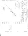
- Fig. 9 shows an example of a dimensionless correlation between the droplet size of the spray and the geometry, process and product parameters.
- the droplet size D 32, global is the Sauter diameter of the spray droplets.
- the dimensionless Weber number We and the Euler number Eu represent the four input process parameters: Spray mass flow rate Q m , static spray pressure P, product density ⁇ and product shear viscosity ⁇ .
- the geometry of the spray nozzle is described with the parameters h sc , d sc , d or and b ch . These abbreviations are explained in table 1 below.
- the Sauter diameter D 32, global was measured by phase-doppler anemometry (PDA) of the droplets sprayed by the spray nozzle apparatus.
- PDA phase-doppler anemometry
Landscapes
- Engineering & Computer Science (AREA)
- Life Sciences & Earth Sciences (AREA)
- Chemical & Material Sciences (AREA)
- Food Science & Technology (AREA)
- Polymers & Plastics (AREA)
- Chemical Kinetics & Catalysis (AREA)
- Zoology (AREA)
- Wood Science & Technology (AREA)
- Microbiology (AREA)
- Mechanical Engineering (AREA)
- General Engineering & Computer Science (AREA)
- Organic Chemistry (AREA)
- Glanulating (AREA)
- Vaporization, Distillation, Condensation, Sublimation, And Cold Traps (AREA)
- Freezing, Cooling And Drying Of Foods (AREA)
- Nozzles (AREA)
- Application Of Or Painting With Fluid Materials (AREA)
Description
- The present invention is directed to a method of controlling the spray droplet size of a spray nozzle apparatus. It is further directed to a spray drying apparatus and a nozzle for such a spray drying apparatus.
- The manufacturing of food powders is realized to a great extent by means of spray drying. This process converts emulsions, suspensions and dispersions into powder. Spray nozzles create droplets, which are dried in hot air by evaporating water. The final powder quality, the final powder texture, the dryer process design, the drying efficiency, the walls fouling behaviour, the operational safety, to name only a few characteristics, are directly linked to the spray quality and thus the atomization process.
US2014/346698 discloses a spray-drying apparatus for high-viscosity fluids comprising means for pressurizing the fluid in a reservoir and/or further pressure varying means for varying a pressure near the nozzles in the nozzle plate for stimulating a controlled breakup of the ejected fluid jet. - Known spray drying processes use atomization nozzles with fixed geometries which cannot be adjusted inline to the process and product conditions during start-up, manufacturing operation and shut-down. Instead operators change the nozzle geometries prior to the production cycle without the possibility to cover all the manufacturing situations. Such nozzles are chosen according to water tables. The manufacturing of food powders happens at significantly higher viscosities compared to water. Typical spray viscosities are within in a range comprised between 1 to 300 mPas. There is no known nozzle apparatus capable to compete with such a wide range.
- As an example, for dairy emulsions at concentrate total solids above 50%, the concentrate viscosity increases in an exponential slope with further increase of total solids. This fact causes problems to spray-drying, if the concentrate viscosity exceeds a design limit of the atomizer nozzles. The design limit is described by means of an atomizer air-core break-down, which stops the creation of droplets and thus stops efficient spray-drying and agglomeration of powders with a required texture. Using prior art spray nozzle apparatus, air-core break downs within atomizer nozzles cannot be determined visually, thus there is currently no means to operate the spray-drying process at its best point without facing issues, such as powder blockages in cones and cyclones, wall fouling or atomizer beard formation, to name just a few issues.
- Since the product and process conditions change from start-up to shut-down of the process the quality of the product achieved varies and product buildup can happen on the nozzle itself and on the walls of the spray-drying equipment, in particular on the walls of the drying chamber, in cones of spray-dryers and cyclones, but also in the conveying ducts between the process units.
- It is a first objective of the present invention to overcome the problems identified with prior art equipment and methods and to enable to operate a spray-drying equipment at its best point and in the most economical way, which involves to be able to spray material having the highest possible total solids content and dry to obtain a dry powder having the maximum total solid content possible, without exceeding the design limit of the atomizers nozzles, which is triggered by the air-core break-down.
- It is an object of the present invention to obtain a method of controlling the spray droplet size of a spray nozzle apparatus which allows controlling of the spray droplet size during the working process. This is particularly useful to have achieve a target spray droplet size distribution defined by the Sauter diameter and to keep a target droplet size distribution constant even with changing product or material properties and changing process conditions.
- This object is achieved by a method comprising the following steps:
- a) providing a paste of a product to be sprayed by a spray nozzle;
- b) continuously determining the shear viscosity (η) of the product paste delivered to the spray nozzle;
- c) determining the mass flow rate (Qm) of the product paste delivered to the spray nozzle;
- d) determining the spray pressure (P) of the product paste delivered to the spray nozzle;
- e) determining the density (ρ) of the product paste delivered to the spray nozzle;
- f) delivering the data obtained in steps b) to e) to a control device comprising a computer and a memory;
- g) calculating control data for adjusting the spray nozzle on the basis of the data obtained in steps b) to e) and on nozzle geometry parameters stored in the memory;
- h) sending the control data as control signals to a control means of the spray nozzle and adjusting the spray nozzle accordingly.
- The shear viscosity is used as input parameter to control the spray nozzle. It allows inline control of the spray nozzle and thus of the spray droplet size, via a stability criterion composed of the spray mass flow rate Qm, the spray pressure P the product density (ρ) and the product viscosity (η).
- This stability criterion ensures to operate the spray-nozzle within design limits, avoiding air-core break-downs in the swirl-chamber of the nozzle.
- Furthermore, a consistent powder agglomeration is achieved in the product during a production cycle independent of the total amount of solid particles (TS) or independent of mass flow rate fluctuations. By this method, a process automation can be achieved through improved and simplified reproducibility and reliability of product properties for different spray-dryer types. A competitive production control is achieved by the inventive method via advanced design of final powder properties like powder moisture, tap density, final agglomerate size and agglomerate stability. Due to the automation the production economy and process efficiency (best-point operation) is also enhanced.
- In a preferred embodiment step b) of continuously determining the shear viscosity (η) of the product paste delivered to the spray nozzle is carried out in a bypass to the product paste stream to the spray nozzle. The bypass has the advantage to measure the shear viscosity independent of the production mass flow rate to suit laminar flow conditions (at Reynolds Re<2300), which allows the measurement of the shear viscosity according to the Differential Pressure Drop Method.
- Preferably, the shear viscosity (η) of the product paste is determined by the following steps:
- b1) providing a constant feed-flow-rate of the product paste at laminar flow conditions;
- b2) determining the mass flow of the product paste;
- b3) delivering the product paste to a pressure-drop-meter and determining the pressure drop;
- b4) calculating the shear viscosity (η) of the product paste on the basis of the laminar mass flow determined in step b2), the pressure drop determined in step b3) and a known product density.
- In case the step b) is carried out in a bypass the calculation in step b4) considers also the bypass-mass-flow-rate.
- Preferably, the determination of the pressure drop in step b3) is carried out according to the differential pressure drop method.
- This method enables inline recording of product shear viscosities e. g. of coffee and milk products before atomization with its specific product characteristics such as highly viscous (1-300mPas) and shear-thinning flow behaviour (determination of 2nd Newtonian plateau viscosity (η). The inline shear viscosity information is necessary to operate the controllable spray-nozzle inline in order to determine the best point configuration of the atomizer and warn in case of design limit achieved. Thus, the inline differential pressure drop method allows a calibration of the shear viscosity for Newtonian and in particular Non-Newtonian shear-thinning fluids based on laboratory rheometers.
- Other techniques to measure the shear viscosity are either underestimating or overestimating the predefined product shear viscosities of dairy and nutrition products (via laboratory rheometer). In particular for shear-thinning fluids, the frequency-based measuring technique, the Coriolis forced measuring method and the quartz-viscosimetry method do not give the possibility to determine the 2nd Newtonian plateau viscosity of shear-thinning fluids due to the lack of information concerning the applied flow field of the method (and thus unknown shear rates).
- Thus, inline recording of the so called second Newtonian plateau viscosity of Non-Newtonian food fluids is possible with the differential pressure drop method and thus allows calibration with predefined product shear viscosity rheograms, which are found from laboratory rheometer measurements.
- According to a second aspect of the invention the object concerning the spray drying apparatus is achieved by the features of
claim 7. - The spray drying apparatus according to the invention provides an inline working means to control spray droplet sizes during spray drying. The spray quality can be judged in terms of the droplet size distribution and its corresponding droplet size mean diameter, i.e. the Sauter diameter D32.
- The spray drying according to the invention helps to achieve the following main manufacturing objectives: a minimum Sauter diameter for fastest and equilibrium water evaporation, an optimum powder agglomeration for consistent powder quality, an equilibrium powder particle size distribution for consistent powder quality, the elimination of scorched particles for consistent powder quality, minimal powder wall fouling and as a consequence reduced risk for cone, duct or conveying pipe powder blockages, minimal spray nozzle fouling and increased dryer safety because of the elimination of dripping and elimination of scorched particles.
- According to a third aspect of the invention a spray nozzle apparatus is provided which comprises means for adjusting the nozzle chamber geometry based on spray drying process parameters, like spray mass flow rate, spray pressure and product parameters, like product density, product shear viscosity which parameters are obtained or evaluated inline during the spray drying process in accordance with a method of the present invention.
- Thus it is possible to adjust the nozzle geometry inline on the basis of parameters responsible for the process yield and the quality of the product achieved. Furthermore the downtimes of a spray drying apparatus equipped with a spray nozzle apparatus according to the invention can be reduced since cleaning times are cut significantly thanks to minimised equipment fouling.
- The nozzle apparatus can be provided with an electric drive adjusting the chamber geometry, the drive being controlled by a control device on the basis of spray drying process parameters and product parameters as mentioned above.
- To modify the chamber geometry, according to an advantageous embodiment of the invention, the apparatus comprises a plunger for adjusting the volume of the nozzle swirl-chamber.
- By moving the plunger into and out of the nozzle chamber by the electric drive an adjustment of the height of the nozzle swirl-chamber is achieved. Thus by moving the plunger, the geometry of the nozzle chamber can be modified inline during the manufacturing process in relation to the product and process parameters as mentioned above.
- Movement of the plunger is achieved by the electric drive which in turn is controlled by a control device like a programmable circuit. This circuit transmits control signals to the electric drive as a function of the above-mentioned parameters.
- In order to achieve the above, according to an advantageous embodiment of the invention the electric drive comprises an electric motor rotatably driving an output shaft, the rotation being transformed in to a longitudinal motion of the plunger via a threaded engagement between the output shaft and the plunger. Thus a mechanical stable and easy to handle configuration is achieved.
- According to an embodiment of the invention, a connecting sleeve is provided which is releasably fixed to the electric drive and is equipped with a longitudinal bore for rotatably accommodating a hollow shaft which transfers the rotating motion of an output shaft of the electric drive to an adjusting pin driving the plunger axially into and out of the nozzle chamber.
- The adjusting pin is provided with a longitudinally extending bore with an inner thread in engagement with an outer thread of the plunger such that a rotating motion of the adjusting pin is transformed into a longitudinal motion of the axially movable plunger.
- According to an advantageous embodiment of the invention, the nozzle chamber is defined by a swirl chamber body being inserted into an inner chamber of a nozzle body, the nozzle body being releasably fixed to the connecting sleeve mentioned above and the swirl chamber body is provided with an opening channel which is arranged in correspondence to the orifice for entering the product material into the swirl chamber of the swirl chamber body. This material can for example be a paste for the production of dairy and nutrition products.
- The swirl chamber can be provided with a helicoidally tightening guiding face for accelerating the paste into the direction of the nozzle orifice to output the material droplets with high speed. Since the material is incompressible, the cone angle of the spray cone and the droplet diameter can be modified according to the product and process parameters inline during the manufacturing process of the product to be achieved by the adjustable movement of the plunger within the swirl chamber.
- According to an advantageous embodiment of the invention, the orifice for introducing the material into the nozzle chamber extends radially to the longitudinal axis of the nozzle and the product material is being transferred to the nozzle via a tube being connected to the orifice.
- To enable a basic modification of the output characteristics of the spray nozzle, the nozzle body is equipped with a releasably mounted orifice plate such that the opening diameter of the nozzle orifice is variable by replacing the orifice plate by a different diameter orifice plate.
- According to a preferred characteristic, a cone angle of a spray mist produced by product droplets and the droplet size are variable by axially moving the plunger relative to the nozzle chamber.
- In the following the invention will be described in further detail by means of an embodiment thereof and the appended drawings.
-
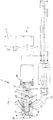
Fig. 1 shows a partial sectional side view of an embodiment of a spray nozzle apparatus according to the invention; -
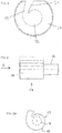
Fig. 2 shows a cross sectional view of a hollow shaft of the spray nozzle apparatus ofFig. 1 ; -
Fig. 3 shows a partial sectional view of an adjusting pin; -
Fig. 4 shows a front view of the swirl chamber body of the spray nozzle apparatus ofFig. 1 ; -
Figs. 5 and 5A depict a side view and a front view (in the direction of arrow A) of the plunger of the spray nozzle apparatus ofFig. 1 ; -
Fig. 6 is a flow chart of the process control method according to the invention; -
Fig. 7 is a flow chart of the differential pressure drop method; -
Fig. 8 shows a principle of a measuring apparatus for the differential pressure drop method and -
Fig. 9 shows an example of a dimensionless correlation between the droplet size of the spray and the geometry, process and product parameters.. - The
spray nozzle apparatus 1 according toFig. 1 comprises anelectric drive 2 provided with an interface (such as a Profibus interface) and a power supply (such as a 24V-DC power supply) at 3 and an electric motor 4 including a transmission connected with 3. - The electric motor 4 drives an output shaft 5 in a rotating manner. The output shaft 5 extends into a longitudinally extending
inner bore 6 of ahollow shaft 7 which is depicted in more detail inFig. 2 . - The
hollow shaft 7 is rotatably accommodated in a longitudinally extending inner bore 8 of a connectingsleeve 9 which can be fixed to the housing of transmission 4 bybolts 10. - The
inner bore 6 of thehollow shaft 7 is equipped with aninner thread 11 which can be brought into a threaded engagement with anouter thread 12 provided on an end piece of an adjusting pin 13 - shown in more detail inFig. 3 - which can be inserted into theinner bore 6 of thehollow shaft 7. - Opposite to the threaded
terminal end 12 of the adjustingpin 13 there is provided a receiving section of the adjustingpin 13, which is formed with aninner bore 14 equipped with aninner thread 15. - The
inner thread 15 of the adjustingpin 13 serves to be brought into a threaded engagement with anouter thread 16 of aplunger 17 more clearly shown inFigs. 5 and 5A . - As can be seen from
Figs. 5 and 5A , theplunger 17 comprises an outercircumferential surface section 18 with a helicoidally shaped cross section corresponding to the shape and size of a receivingsection 19 of aswirl chamber body 20 accommodated in a nozzle body 23 which is mounted to the connectingsleeve 9 as shown inFig. 4 . - The
swirl chamber body 20 comprises a lateral ortangential inlet channel 21 for introducing paste material or the like into theswirl chamber 22 of theswirl chamber body 20. - Material to be transported through the
inlet channel 21 into theswirl chamber 22 can enter the nozzle body 23 via a first orifice 24 or inlet orifice which extends radially to the commonlongitudinal axis 28 of the nozzle body 23 and the connectingsleeve 9. To this end there is atube 25 connected to the first orifice 24 of the nozzle body 23 defining an inlet opening of theapparatus 1. - Paste or paste like material delivered to the nozzle body 23 via the
tube 25 enters the nozzle body 23 via the first orifice 24 and enters theswirl chamber 22 via theinlet channel 21. - The
swirl chamber 22 is equipped with an axially extending through hole having an inner circumferential surface section with a helicoidally shaped cross section, thus forming a helicoidal, spiral-type guiding face that serves to accelerate the material into the direction of a second orifice 26 or nozzle orifice of the nozzle body 23 defining an outlet opening of theapparatus 1. Anorifice plate 27 is provided between the axial outlet of theswirl chamber 22 and the second orifice 26 by whichorifice plate 27 the opening angle of the spray cone can be basically adjusted. -
Fig. 1 shows theplunger 17 closing the first orifice 24. Driving the motor 4 makes thehollow shaft 7 rotate and thus also makes the adjustingpin 13 rotate about its longitudinal axis. Theplunger 17 is connected to theinner thread 15 of the adjustingpin 13 via theouter thread 16 and can only execute a movement relative to theswirl chamber body 20 along thelongitudinal axis 28 of theplunger 17 but can not rotate relative to theswirl chamber body 20. Thus a rotation of the adjustingpin 13 is transformed in to an axial movement of theplunger 19 relative to theswirl chamber body 20. - By this movement of the
plunger 18 the axial width of the first orifice 24 and the geometry of theswirl chamber 22 and thus the nozzle chamber can be modified. Since theelectric drive 2 is controlled by process and product parameters which in turn are obtained or evaluated inline during the manufacturing process of the powder to be achieved, the control takes place inline with the manufacturing process of the powder. To achieve this, the control circuit provides theelectric drive 2 with signals such that theplunger 17 is being moved axially in the direction of thelongitudinal axis 28 as shown inFig. 1 . By this movement of theplunger 17 the spray droplet size of the sprayed material to be atomized can be adjusted towards the minimum Sauter diameter possible for a given set of input parameters. - Measuring these input parameters inline with the production process of the powder according to the method of the invention allows adjusting of the droplet size towards the minimum Sauter diameter possible inline and thus makes it possible to consider the complete range of spray viscosities during the production process of the powder to be produced.
- The product paste entering the swirl chamber through the
inlet channel 21 follows a helicoidal and spiral way due to the spiral-type cross section design of the swirl chamber in a combined circumferential and axial direction towards the nozzle orifice 26. This design accelerates the traveling speed of the product paste flow in the swirl chamber, provided that the mass flow of the product paste is constant. The product paste is leaving the spray nozzle through theorifice plate 27 and the nozzle orifice 26 as a cone-shapedfilm 29 with a cone tip angle α wherein thefilm 29 atomizes into droplets forming a spray mist. The cone tip angle α is directly proportional to the traveling speed of the product paste in the nozzle orifice 26, i.e. the higher the traveling speed is, the larger the cone tip angle becomes and the smaller the droplets size. - A cone tip angle α of 0° generates no atomization and, in a realized example, a cone tip angle α of 100° generates droplets having a Sauter-diameter of D32 = 30 µm. The wider the cone tip angle α is, the smaller the droplets become so that the droplet size can be controlled by the cone tip angle α and thus by the traveling speed of the product paste in the nozzle orifice 26
-
Fig. 6 is a flowchart of the process control method according to the present invention. The product paste inFig. 6 indicated as "concentrate" is delivered to adosing point 30, which leads a part of the product paste stream into abypass line 32. The majority of the product paste stream is directed into a mainproduct paste line 34. Thebypass line 32 is redirected into the mainproduct paste line 34 at aline junction 36 downstream of a differential pressuredrop measuring apparatus 38 provided in thebypass line 32. - Downstream of the line junction 36 a
mass flow meter 40, adensity meter 42 and aspray pressure probe 44 are provided in the main product paste line. Downstream of thespray pressure probe 44 the mainproduct paste line 34 enters thespray nozzle apparatus 1 shown inFig. 1 throughtube 25. The product paste delivered to thespray nozzle apparatus 1 is then sprayed into aspray drying chamber 46. - The differential pressure
drop measuring apparatus 38 determines the shear rate and the shear viscosity η of the product paste delivered to the spray nozzle. The data of the shear rate and shear viscosity η are delivered from the differential pressuredrop measuring apparatus 38 to a control device (SPS-control) 48. In the same manner, the product paste mass flow rate Qm determined in themass flow meter 40, the product paste density ρ determined in thedensity meter 42 and the spray pressure P of the product paste determined in thespray pressure probe 44 are also delivered to thecontrol device 48. -
Control device 48 comprises a computer which calculates an output control parameter based on the above data delivered to thecontrol device 48 and on the basis of known spray nozzle geometry parameters stored in a memory of thecontrol device 48. The output control parameter is delivered to thespray nozzle apparatus 1 in order to adjust theswirl chamber piston 17 to a calculated position in order to obtain a desired swirl chamber volume. - The following equations 1-7 describe the solving procedure how to control the plunger position (given with hsc) based on a change in the paste shear viscosity η.
- Accordingly the solving procedure is applied for a change in mass flow rate Qm and paste density ρ.
- Universal Massflow-Characterisation of Pressure Swirl Nozzle Flows:


-
Fig. 7 is a flowchart of the differential pressure drop method as applied in the differential pressuredrop measuring apparatus 38. Afeed pump 50 is provided in thebypass line 32 downstream ofdosing point 30. Thefeed pump 50 ensures a constant feed-flow-rate in the differential pressuredrop measuring apparatus 38 to enable shear rates which cover the second Newtonian viscosity plateau. Downstream of the feed pump 50 amass flow meter 52 is provided through which the product paste in thebypass line 32 is directed into apressure drop meter 54. The shear viscosity (η) of the product paste in thebypass line 32 is calculated from the mass flow measured in themass flow meter 52, the known product density of the product paste and the pressure drop measured in thepressure drop meter 54. This calculation is either made in a computer (not shown) of the differential pressuredrop measuring apparatus 38 or, the respective data are delivered to thecontrol device 48 and the shear viscosity η is calculated in the computer of thecontrol device 48. In order to consider the fact that the pressure drop is measured in abypass line 32 the bypass mass flowrate is adjusted by thefeed pump 50 until the shear-rate is such, that the second Newtonian plateau viscosity can be measured by the pressure drop-meter 54 within laminar flow conditions.. - In the present example the
dosing point 30 regulates the bypass flow rate to keep the bypass flow pressure <20 bar at laminar flow conditions, e.g.flow rates <1000kg/h. -
Fig. 8 shows the principle of a measuring apparatus (pressure drop meter) for the differential pressure drop method for determination of the second Newtonian plateau viscosity using three independent pressure drop recordings at three different shear-rates. - The
pressure drop meter 100 comprises a tube having afluid inlet section 102 and afluid outlet section 104 and three pressuredrop measuring sections 106, 108, 110 provided between theinlet section 102 and theoutlet section 104. The first pressure drop measuring section 106 which is close to theinlet section 102 has a first internal diameter d1 and a first axial length l1. A firstdifferential pressure meter 112 measuring a first pressure drop Δp1 is connected to the first pressure drop measuring section 106 in a commonly known matter wherein the axial distance L1 between the two static pressure measuring openings in the wall of the first pressure drop measuring section 106 is substantially equal to the length l1 of the first pressure drop measuring section 106. - The second pressure
drop measuring section 108 is provided downstream of the first pressure drop measuring section 106. The internal diameter d2 of the second pressuredrop measuring section 108 is smaller than the diameter d1 of the first pressure drop measuring section. The length l2 of the second pressuredrop measuring section 108 is shorter than the length of the first pressure drop measuring section 106. The second pressuredrop measuring section 108 comprises a seconddifferential pressure meter 114 measuring a second pressure drop Δp2 wherein the distance L2 between the two static pressure measuring openings in the wall of the second pressuredrop measuring section 108 is shorter than the distance L1 of the firstdifferential pressure meter 112. - A third pressure drop measuring section 110 is provided downstream of the second pressure
drop measuring section 108 and the third pressure drop measuring section 110 opens into theoutlet section 104. The internal diameter d3 of the third pressure drop measuring section 110 is smaller than the diameter d2 of the second pressuredrop measuring section 108 and the length l3 of the third pressure drop measuring section is shorter than the length l2 of the second pressure drop measuring section. The third pressure drop measuring section 110 comprises in a commonly known manner a thirddifferential pressure meter 116 measuring a third pressure drop Δp3. The distance L3 between the two static pressure measuring openings in the wall of the third pressure drop measuring section 110 is shorter than the distance L2 of the seconddifferential pressure meter 114. - The differential
pressure drop meter 100 allows the measurement of three independent pressure drop recordings of the first, the second and the third differential pressure drop meters. Utilizing these three differential pressure drop probes in series, a single mass flow rate causes three increasing wall shear rates with the decreasing tube diameter. - The following equation 8 is used to calculate the shear viscosity η for laminar tube flows (Re<2300), applied to all 3 differential pressures Δp1, Δp2 and Δp3 (respectively measured at 112, 114 and 116,
figure 8 ), by replacing Δpi and the corresponding tube dimensions (Ri and Li) in equation 8:
Only, if the shear viscosity ηi is equal (η1=η2=η3) between the 3 differential pressures, the 2nd Newtonian shear viscosity is found and used e.g. inequation 
- Ri: tube radius (R1, R2 and R3) in [m]
- Δpi: tube pressure drop (Δp1, Δp2 and Δp3) in [Pa]
- ρ : product density in [kg/m3]
- Qm: mass flow rate in [kg/s]
- Li: tube length (distance L1, L2 and L3) in [m]
-
Fig. 9 shows an example of a dimensionless correlation between the droplet size of the spray and the geometry, process and product parameters. The droplet size D32, global is the Sauter diameter of the spray droplets. The dimensionless Weber number We and the Euler number Eu represent the four input process parameters: Spray mass flow rate Qm, static spray pressure P, product density ρ and product shear viscosity η. The geometry of the spray nozzle is described with the parameters hsc, dsc, dor and bch. These abbreviations are explained in table 1 below.
The Sauter diameter D32, global was measured by phase-doppler anemometry (PDA) of the droplets sprayed by the spray nozzle apparatus.
The measured Sauter diameter D32, global was correlated to the corresponding geometry, process and product parameters, which were varied in the frame of the PDA measurements to achieve a correlation as shown infigure 9 .Table 1: Abbreviations and formula Symbol, Abbreviation Description Units D32,global Global Sauter diameter as found from PDA measurements of spray [m] dsc Swirl chamber diameter (smallest diameter of swirl chamber spiral) [m] hsc Swirl chamber height (axial height of swirl chamber) [m] dor Orifice diameter (diameter of opening made in orifice plate) [m] bch Width of swirl chamber inlet channel (smallest width of inlet channel which leads into the swirl chamber) [m] We Weber number - 
Eu Euler number - 
Re Reynolds number - 
Ubulk Bulk velocity at swirl chamber inlet [m/s] 
Qm Mass flow rate [kg/s] P Spray pressure [Pa] ρliquid Liquid density [kg/m3] ηliquid Liquid shear viscosity [Pas] σliquid Surface tension [N/m] PDA Phase-Doppler Anemometry - - The invention should not be regarded as being limited to the embodiment shown and described in the above but various modifications and combinations of features may be carried out without departing from the scope of the following claims.
Claims (19)
- Method of controlling the spray droplet size of a spray nozzle apparatus, in particular for the manufacturing of food powders, delivered to the spray nozzle wherein the method comprises the following steps:a) providing a paste of a product to be sprayed by a spray nozzle;b) continuously determining the shear viscosity (η) of the product paste delivered to the spray nozzle;c) determining the mass flow rate (Qm) of the product paste delivered to the spray nozzle;d) determining the static pressure (P) of the product paste delivered to the spray nozzle;e) determining the density (ρ) of the product paste delivered to the spray nozzle;f) delivering the data obtained in steps b) to e) to a control device comprising a computer and a memory;g) calculating control data for adjusting the spray nozzle on the basis of the data obtained in steps b) to e) and on nozzle geometry parameters stored in the memory;h) sending the control data as control signals to a control means of the spray nozzle and adjusting the spray nozzle accordingly.
- Method according to claim 1, wherein the step b) of continuously determining the shear viscosity (η) of the product paste delivered to the spray nozzle is carried out in a bypass to the product paste stream to the spray nozzle.
- Method according to claim 1, wherein the shear viscosity (η) of the product paste is determined by the following steps:b1) providing a constant feed-flow-rate of the product paste;b2) determining the mass flow of the product paste;b3) delivering the product paste to a pressure-drop-meter and determining the pressure drop;b4) calculating the shear rate and shear viscosity (η) of the product paste on the basis of the mass flow determined in step b2), the pressure drop determined in step b3) and a known product density.
- Method according to claim 2 and 3, wherein the calculation in step b4) considers also the bypass-mass-flow-rate.
- Method according to claim 3 or 4, wherein the determination of the pressure drop in step b3) is carried out according to the differential pressure drop method.
- Method according to claim 5, wherein the adjustment of the spray nozzle in step h) is carried out by changing the volume of a swirl chamber provided in the spray nozzle.
- Spray drying apparatus for carrying out a method as defined in one of the preceding claims, comprising a spray nozzle apparatus having a spray nozzle provided with a nozzle orifice (26) for outputting spray droplets of a product to be dried and an inlet orifice (24) for transferring said product into a nozzle chamber (22) characterized by an apparatus for adjusting the size of the outputted droplets inline during the spray process on the basis of the control data calculated in step g) of the method.
- Spray nozzle apparatus in the spray drying apparatus of claim 7, wherein the apparatus comprises means for adjusting the nozzle chamber geometry based on spray drying process parameters and product parameters obtained inline during the spray drying process.
- Nozzle apparatus according to claim 8, characterized by an electric drive (2) adjusting the chamber geometry, said drive (2) being controlled by a control device on the basis of spray drying process parameters and product parameters.
- Nozzle apparatus according to claim 8 or 9, characterized by a plunger (17) adjusting the size of said inlet orifice (24) and/or the volume of said nozzle chamber (22).
- Nozzle apparatus according to claim 10, characterized in that said plunger (17) being movable into and out of said nozzle chamber (22) by said electric drive (2) adjusting the inlet orifice width and/or the height of said nozzle chamber (22).
- Nozzle apparatus according to any one of claims 10 or 11, characterized in that said electric drive (2) comprises an electric motor (4) rotatingly driving an output shaft (5), said rotation being transferred to a longitudinal motion of said plunger (17) via a threaded engagement between said output shaft (5) and said plunger (17).
- Nozzle apparatus according to any one of claims 9 to 12, characterized by a connecting sleeve (9) being releasably fixed to said electrical drive (2) and providing a longitudinal bore for rotatingly accommodating a hollow shaft (7) which transfers the rotating motion of an output shaft (5) of said electrical drive (2) to an adjusting pin (13) driving a plunger (17) into and out of said nozzle chamber (22).
- Nozzle apparatus according to claim 13, characterized in that said adjusting pin (13) is provided with a longitudinally extending axial bore (14) with an inner thread (15) in engagement with an outer thread (16) of said plunger (17) such that a rotating motion of said adjusting pin (13) is transferred to a longitudinal motion of said axially movable plunger (17).
- Nozzle apparatus according to claim 13 or claim 14, characterized in that said nozzle chamber (22) is provided by a swirl chamber body (20) being inserted into an inner chamber of a nozzle body (23), said nozzle body (23) being releasably fixed to said connecting sleeve (9) and said swirl chamber body (20) being provided with an opening channel (21) which is arranged in correspondence to said inlet orifice (24) for entering said material into a swirl chamber (22) of said swirl chamber body (20).
- Nozzle apparatus according to claim 15, characterized in that said swirl chamber (22) is provided with a helicoidally tightening guiding face for accelerating said product into the direction of the nozzle orifice (26).
- Nozzle apparatus according to any one of claims 8 to 16, characterized in that said inlet orifice (24) extends radially to said longitudinal axis (28) of said nozzle and said product being transferred to said nozzle via a tubing (25) being connected with said inlet orifice (24).
- Nozzle apparatus according to any one of claims 8 to 17, characterized in that said nozzle orifice (26) is equipped with a releasably mounted orifice plate (27) such that the opening diameter of said nozzle orifice (26) is variable by replacing the orifice plate (27) by a different diameter orifice plate.
- Nozzle apparatus according to any one of claims 10 to 18, characterized in that a cone angle of a spray mist produced by product droplets and the droplet size are variable by axially moving the plunger (17) relative to the nozzle chamber (22).
Applications Claiming Priority (2)
| Application Number | Priority Date | Filing Date | Title |
|---|---|---|---|
| EP14200753 | 2014-12-31 | ||
| PCT/EP2015/081013 WO2016107795A1 (en) | 2014-12-31 | 2015-12-22 | Method of controlling the spray droplet size of a spray nozzle apparatus for spray-drying applications, spray drying apparatus and nozzle therefore |
Publications (2)
| Publication Number | Publication Date |
|---|---|
| EP3240435A1 EP3240435A1 (en) | 2017-11-08 |
| EP3240435B1 true EP3240435B1 (en) | 2018-10-03 |
Family
ID=52282578
Family Applications (1)
| Application Number | Title | Priority Date | Filing Date |
|---|---|---|---|
| EP15817360.9A Active EP3240435B1 (en) | 2014-12-31 | 2015-12-22 | Method of controlling the spray droplet size of a spray nozzle apparatus for spray-drying applications, spray drying apparatus and nozzle therefore |
Country Status (9)
| Country | Link |
|---|---|
| US (1) | US10265717B2 (en) |
| EP (1) | EP3240435B1 (en) |
| CN (1) | CN107105728B (en) |
| AU (1) | AU2015373483B2 (en) |
| ES (1) | ES2701877T3 (en) |
| MX (1) | MX373273B (en) |
| PH (1) | PH12017500673B1 (en) |
| RU (1) | RU2719034C2 (en) |
| WO (1) | WO2016107795A1 (en) |
Cited By (1)
| Publication number | Priority date | Publication date | Assignee | Title |
|---|---|---|---|---|
| DE102024126194A1 (en) * | 2024-09-12 | 2026-03-12 | Bayerische Motoren Werke Aktiengesellschaft | Manufacturing process and manufacturing apparatus for producing a component for a battery cell of an energy storage device |
Families Citing this family (5)
| Publication number | Priority date | Publication date | Assignee | Title |
|---|---|---|---|---|
| US10156241B2 (en) * | 2017-05-01 | 2018-12-18 | General Electric Company | Controlling a wet compression system |
| RU2669217C1 (en) * | 2018-01-31 | 2018-10-09 | Олег Савельевич Кочетов | Catalysts drying and calcination plant |
| CN109078345A (en) * | 2018-08-17 | 2018-12-25 | 无锡科技职业学院 | A kind of atomizing fluid bed dryer |
| JP2025541713A (en) * | 2022-12-02 | 2025-12-23 | セラン バイオサイエンス,エルエルシー | Method and system for spray drying temperature-sensitive products |
| CN118681720B (en) * | 2024-08-22 | 2024-12-06 | 河北御芝林药业有限公司 | Traditional Chinese medicine atomization granulation control method and device, electronic equipment and storage medium |
Family Cites Families (24)
| Publication number | Priority date | Publication date | Assignee | Title |
|---|---|---|---|---|
| DE935495C (en) | 1951-11-30 | 1955-11-24 | Shell Refining & Marketing Com | Pressure atomization burner |
| US3981957A (en) * | 1975-08-06 | 1976-09-21 | Exxon Research And Engineering Company | Process for preparing finely divided polymers |
| DE19617685C2 (en) | 1996-05-03 | 2002-11-07 | Deutsch Zentr Luft & Raumfahrt | Kegelstrahldralldüse |
| WO1997048496A1 (en) * | 1996-06-21 | 1997-12-24 | Hughes Technology Group L.L.C. | Micro-atomizing device |
| EP1132615B1 (en) * | 2000-03-07 | 2006-11-08 | Matsushita Electric Industrial Co., Ltd. | Fluid dispenser |
| JP3801967B2 (en) * | 2001-08-28 | 2006-07-26 | 株式会社いけうち | NOZZLE AND METHOD OF INJECTING FLUID TO INTERNAL PERIPHERAL SURFACE BY NOZZLE |
| JP2006512102A (en) * | 2002-04-11 | 2006-04-13 | メディミューン・ヴァクシンズ・インコーポレーテッド | Preservation of bioactive materials by spray drying |
| US6880350B2 (en) * | 2002-09-13 | 2005-04-19 | Isothermal Systems Research, Inc. | Dynamic spray system |
| CN100384545C (en) * | 2002-09-30 | 2008-04-30 | 松下电器产业株式会社 | Fluid discharge device and fluid discharge method |
| DE10251697A1 (en) * | 2002-11-06 | 2004-05-19 | Robert Bosch Gmbh | Dosing device for liquid fuel, especially for liquid reformer or after-burner, has nozzle body with downstream carrying element with spin insert on spray output side and at least one spray opening |
| US7470447B2 (en) * | 2003-02-14 | 2008-12-30 | Panasonic Corporation | Method and device for discharging fluid |
| US7647883B2 (en) * | 2004-04-16 | 2010-01-19 | Panasonic Corporation | Fluid injection method and apparatus and display panel |
| JP4539218B2 (en) * | 2004-08-02 | 2010-09-08 | 日本精工株式会社 | Electric power steering device |
| DE102006054786A1 (en) | 2006-11-21 | 2008-05-29 | Dürr Systems GmbH | Operating method for a nebulizer and corresponding coating device |
| US8689459B2 (en) * | 2006-12-07 | 2014-04-08 | Friesland Brands B.V. | Method and apparatus for spray drying and powder produced using said method |
| US7980483B2 (en) * | 2008-10-13 | 2011-07-19 | Eaton Corporation | Injector for a fluid injection system |
| WO2011133420A2 (en) * | 2010-04-19 | 2011-10-27 | Eaton Corporation | Pressure swirl atomizer with swirl-assisting configuration |
| CN103261662B (en) * | 2010-12-20 | 2016-01-20 | 丰田自动车株式会社 | fuel injection valve |
| EP2679800A4 (en) * | 2011-02-23 | 2015-10-21 | Toyota Motor Co Ltd | FUEL INJECTION VALVE |
| DE102011101898A1 (en) * | 2011-05-18 | 2012-11-22 | Meadwestvaco Calmar Gmbh | Fluidaustragkopf |
| EP2559480A1 (en) * | 2011-08-16 | 2013-02-20 | Nederlandse Organisatie voor toegepast -natuurwetenschappelijk onderzoek TNO | Method of spray-drying and apparatus for spray-drying. |
| RU118730U1 (en) * | 2011-11-21 | 2012-07-27 | Общество с ограниченной ответственностью Научно-технический Центр "ТАТА" - ООО НТЦ "ТАТА" | SPRAY DRYER (OPTIONS) |
| US8978364B2 (en) * | 2012-05-07 | 2015-03-17 | Tenneco Automotive Operating Company Inc. | Reagent injector |
| MX377707B (en) * | 2012-10-17 | 2025-03-11 | Corbion Biotech Inc | MICROALGAE FLOUR GRANULES AND PROCESS FOR PREPARING THE SAME. |
-
2015
- 2015-12-22 CN CN201580068387.7A patent/CN107105728B/en active Active
- 2015-12-22 EP EP15817360.9A patent/EP3240435B1/en active Active
- 2015-12-22 WO PCT/EP2015/081013 patent/WO2016107795A1/en not_active Ceased
- 2015-12-22 US US15/540,454 patent/US10265717B2/en active Active
- 2015-12-22 ES ES15817360T patent/ES2701877T3/en active Active
- 2015-12-22 AU AU2015373483A patent/AU2015373483B2/en active Active
- 2015-12-22 RU RU2017126887A patent/RU2719034C2/en active
- 2015-12-22 MX MX2017008490A patent/MX373273B/en active IP Right Grant
-
2017
- 2017-04-10 PH PH12017500673A patent/PH12017500673B1/en unknown
Non-Patent Citations (1)
| Title |
|---|
| None * |
Cited By (2)
| Publication number | Priority date | Publication date | Assignee | Title |
|---|---|---|---|---|
| DE102024126194A1 (en) * | 2024-09-12 | 2026-03-12 | Bayerische Motoren Werke Aktiengesellschaft | Manufacturing process and manufacturing apparatus for producing a component for a battery cell of an energy storage device |
| WO2026057109A1 (en) * | 2024-09-12 | 2026-03-19 | Bayerische Motoren Werke Aktiengesellschaft | Production method and production device for producing a component for a battery cell of an energy storage device |
Also Published As
| Publication number | Publication date |
|---|---|
| PH12017500673A1 (en) | 2017-10-09 |
| WO2016107795A1 (en) | 2016-07-07 |
| AU2015373483A1 (en) | 2017-04-20 |
| CN107105728B (en) | 2018-09-28 |
| RU2017126887A (en) | 2019-01-31 |
| US10265717B2 (en) | 2019-04-23 |
| PH12017500673B1 (en) | 2020-01-24 |
| RU2017126887A3 (en) | 2019-06-26 |
| WO2016107795A8 (en) | 2018-08-09 |
| MX2017008490A (en) | 2017-09-19 |
| RU2719034C2 (en) | 2020-04-16 |
| ES2701877T3 (en) | 2019-02-26 |
| MX373273B (en) | 2020-05-18 |
| EP3240435A1 (en) | 2017-11-08 |
| CN107105728A (en) | 2017-08-29 |
| US20180001334A1 (en) | 2018-01-04 |
| AU2015373483B2 (en) | 2019-10-10 |
Similar Documents
| Publication | Publication Date | Title |
|---|---|---|
| EP3240984B1 (en) | Spray nozzle apparatus for spray-drying applications | |
| US10265717B2 (en) | Method of controlling the spray droplet size of a spray nozzle apparatus for spray-drying applications, spray drying apparatus and nozzle therefore | |
| O'Sullivan et al. | Atomisation technologies used in spray drying in the dairy industry: A review | |
| CA2825400C (en) | External mixing pressurized two-fluid nozzle and a spray drying method | |
| CN101821026A (en) | Device and method for atomizing and lubricating roller | |
| JP7118997B2 (en) | Equipment for spray deposition | |
| CA1061752A (en) | Method and device for metering and dispensing liquid materials | |
| US10520409B2 (en) | Method of continuously measuring the shear viscosity of a product paste | |
| AU782291B2 (en) | Method and device for atomizing liquids | |
| CN105818532B (en) | Equipment for dispensing powder to printed pages | |
| JP2006136857A (en) | Fluidized bed apparatus and granular material processing method | |
| CN210729917U (en) | Paint spraying flow control system | |
| CN207995887U (en) | A kind of online drawing-in device of wheat germ | |
| CN104307658A (en) | High viscosity fluid atomization spraying nozzle | |
| TH56700A (en) | Methods and equipment for liquid atomization. | |
| RU2559285C1 (en) | Ultrasonic fluid sprayer | |
| RU2708839C1 (en) | Apparatus for production of encapsulated products | |
| CN108378298A (en) | A kind of online drawing-in device of wheat germ | |
| RU2584055C1 (en) | Desuperheater | |
| Kamimura et al. | Experimental investigation of hydraulic performance of twin-fluid mist generators for high viscous liquids | |
| Mescher et al. | Designing thread forming rotary atomizers by similarity trials | |
| DE1270740B (en) | Device for spraying or atomizing liquid media | |
| Yang et al. | New development of far distance coaxial powder feeding system |
Legal Events
| Date | Code | Title | Description |
|---|---|---|---|
| PUAI | Public reference made under article 153(3) epc to a published international application that has entered the european phase |
Free format text: ORIGINAL CODE: 0009012 |
|
| 17P | Request for examination filed |
Effective date: 20170731 |
|
| AK | Designated contracting states |
Kind code of ref document: A1 Designated state(s): AL AT BE BG CH CY CZ DE DK EE ES FI FR GB GR HR HU IE IS IT LI LT LU LV MC MK MT NL NO PL PT RO RS SE SI SK SM TR |
|
| AX | Request for extension of the european patent |
Extension state: BA ME |
|
| DAV | Request for validation of the european patent (deleted) | ||
| DAX | Request for extension of the european patent (deleted) | ||
| GRAP | Despatch of communication of intention to grant a patent |
Free format text: ORIGINAL CODE: EPIDOSNIGR1 |
|
| INTG | Intention to grant announced |
Effective date: 20180622 |
|
| RIN1 | Information on inventor provided before grant (corrected) |
Inventor name: SANDERS, DALE RICHARD Inventor name: SCHMIED, CHRISTIAN Inventor name: STRANZINGER, MICHAEL Inventor name: NYDEGGER, MARTIN Inventor name: FANKHAUSER, PETER Inventor name: ERDMANN, PETER |
|
| RIN1 | Information on inventor provided before grant (corrected) |
Inventor name: NYDEGGER, MARTIN Inventor name: STRANZINGER, MICHAEL Inventor name: SCHMIED, CHRISTIAN Inventor name: FANKHAUSER, PETER Inventor name: SANDERS, DALE RICHARD Inventor name: WALTHERT, GERHARD Inventor name: ERDMANN, PETER |
|
| GRAS | Grant fee paid |
Free format text: ORIGINAL CODE: EPIDOSNIGR3 |
|
| GRAA | (expected) grant |
Free format text: ORIGINAL CODE: 0009210 |
|
| AK | Designated contracting states |
Kind code of ref document: B1 Designated state(s): AL AT BE BG CH CY CZ DE DK EE ES FI FR GB GR HR HU IE IS IT LI LT LU LV MC MK MT NL NO PL PT RO RS SE SI SK SM TR |
|
| REG | Reference to a national code |
Ref country code: GB Ref legal event code: FG4D |
|
| REG | Reference to a national code |
Ref country code: CH Ref legal event code: EP Ref country code: AT Ref legal event code: REF Ref document number: 1047653 Country of ref document: AT Kind code of ref document: T Effective date: 20181015 |
|
| REG | Reference to a national code |
Ref country code: IE Ref legal event code: FG4D Ref country code: DE Ref legal event code: R096 Ref document number: 602015017641 Country of ref document: DE |
|
| REG | Reference to a national code |
Ref country code: NL Ref legal event code: FP |
|
| REG | Reference to a national code |
Ref country code: LT Ref legal event code: MG4D |
|
| REG | Reference to a national code |
Ref country code: ES Ref legal event code: FG2A Ref document number: 2701877 Country of ref document: ES Kind code of ref document: T3 Effective date: 20190226 |
|
| REG | Reference to a national code |
Ref country code: AT Ref legal event code: MK05 Ref document number: 1047653 Country of ref document: AT Kind code of ref document: T Effective date: 20181003 |
|
| PG25 | Lapsed in a contracting state [announced via postgrant information from national office to epo] |
Ref country code: LV Free format text: LAPSE BECAUSE OF FAILURE TO SUBMIT A TRANSLATION OF THE DESCRIPTION OR TO PAY THE FEE WITHIN THE PRESCRIBED TIME-LIMIT Effective date: 20181003 Ref country code: NO Free format text: LAPSE BECAUSE OF FAILURE TO SUBMIT A TRANSLATION OF THE DESCRIPTION OR TO PAY THE FEE WITHIN THE PRESCRIBED TIME-LIMIT Effective date: 20190103 Ref country code: AT Free format text: LAPSE BECAUSE OF FAILURE TO SUBMIT A TRANSLATION OF THE DESCRIPTION OR TO PAY THE FEE WITHIN THE PRESCRIBED TIME-LIMIT Effective date: 20181003 Ref country code: FI Free format text: LAPSE BECAUSE OF FAILURE TO SUBMIT A TRANSLATION OF THE DESCRIPTION OR TO PAY THE FEE WITHIN THE PRESCRIBED TIME-LIMIT Effective date: 20181003 Ref country code: IS Free format text: LAPSE BECAUSE OF FAILURE TO SUBMIT A TRANSLATION OF THE DESCRIPTION OR TO PAY THE FEE WITHIN THE PRESCRIBED TIME-LIMIT Effective date: 20190203 Ref country code: CZ Free format text: LAPSE BECAUSE OF FAILURE TO SUBMIT A TRANSLATION OF THE DESCRIPTION OR TO PAY THE FEE WITHIN THE PRESCRIBED TIME-LIMIT Effective date: 20181003 Ref country code: BG Free format text: LAPSE BECAUSE OF FAILURE TO SUBMIT A TRANSLATION OF THE DESCRIPTION OR TO PAY THE FEE WITHIN THE PRESCRIBED TIME-LIMIT Effective date: 20190103 Ref country code: LT Free format text: LAPSE BECAUSE OF FAILURE TO SUBMIT A TRANSLATION OF THE DESCRIPTION OR TO PAY THE FEE WITHIN THE PRESCRIBED TIME-LIMIT Effective date: 20181003 Ref country code: PL Free format text: LAPSE BECAUSE OF FAILURE TO SUBMIT A TRANSLATION OF THE DESCRIPTION OR TO PAY THE FEE WITHIN THE PRESCRIBED TIME-LIMIT Effective date: 20181003 Ref country code: HR Free format text: LAPSE BECAUSE OF FAILURE TO SUBMIT A TRANSLATION OF THE DESCRIPTION OR TO PAY THE FEE WITHIN THE PRESCRIBED TIME-LIMIT Effective date: 20181003 |
|
| PG25 | Lapsed in a contracting state [announced via postgrant information from national office to epo] |
Ref country code: RS Free format text: LAPSE BECAUSE OF FAILURE TO SUBMIT A TRANSLATION OF THE DESCRIPTION OR TO PAY THE FEE WITHIN THE PRESCRIBED TIME-LIMIT Effective date: 20181003 Ref country code: GR Free format text: LAPSE BECAUSE OF FAILURE TO SUBMIT A TRANSLATION OF THE DESCRIPTION OR TO PAY THE FEE WITHIN THE PRESCRIBED TIME-LIMIT Effective date: 20190104 Ref country code: SE Free format text: LAPSE BECAUSE OF FAILURE TO SUBMIT A TRANSLATION OF THE DESCRIPTION OR TO PAY THE FEE WITHIN THE PRESCRIBED TIME-LIMIT Effective date: 20181003 Ref country code: PT Free format text: LAPSE BECAUSE OF FAILURE TO SUBMIT A TRANSLATION OF THE DESCRIPTION OR TO PAY THE FEE WITHIN THE PRESCRIBED TIME-LIMIT Effective date: 20190203 Ref country code: AL Free format text: LAPSE BECAUSE OF FAILURE TO SUBMIT A TRANSLATION OF THE DESCRIPTION OR TO PAY THE FEE WITHIN THE PRESCRIBED TIME-LIMIT Effective date: 20181003 |
|
| REG | Reference to a national code |
Ref country code: NL Ref legal event code: PD Owner name: SOCIETE DES PRODUITS NESTLE S.A.; CH Free format text: DETAILS ASSIGNMENT: CHANGE OF OWNER(S), MERGE; FORMER OWNER NAME: NESTEC S.A. Effective date: 20190620 |
|
| REG | Reference to a national code |
Ref country code: DE Ref legal event code: R097 Ref document number: 602015017641 Country of ref document: DE |
|
| RAP2 | Party data changed (patent owner data changed or rights of a patent transferred) |
Owner name: SOCIETE DES PRODUITS NESTLE S.A. |
|
| REG | Reference to a national code |
Ref country code: CH Ref legal event code: PCOW |
|
| PG25 | Lapsed in a contracting state [announced via postgrant information from national office to epo] |
Ref country code: DK Free format text: LAPSE BECAUSE OF FAILURE TO SUBMIT A TRANSLATION OF THE DESCRIPTION OR TO PAY THE FEE WITHIN THE PRESCRIBED TIME-LIMIT Effective date: 20181003 Ref country code: IT Free format text: LAPSE BECAUSE OF FAILURE TO SUBMIT A TRANSLATION OF THE DESCRIPTION OR TO PAY THE FEE WITHIN THE PRESCRIBED TIME-LIMIT Effective date: 20181003 |
|
| PLBE | No opposition filed within time limit |
Free format text: ORIGINAL CODE: 0009261 |
|
| STAA | Information on the status of an ep patent application or granted ep patent |
Free format text: STATUS: NO OPPOSITION FILED WITHIN TIME LIMIT |
|
| REG | Reference to a national code |
Ref country code: GB Ref legal event code: 732E Free format text: REGISTERED BETWEEN 20190801 AND 20190807 |
|
| PG25 | Lapsed in a contracting state [announced via postgrant information from national office to epo] |
Ref country code: RO Free format text: LAPSE BECAUSE OF FAILURE TO SUBMIT A TRANSLATION OF THE DESCRIPTION OR TO PAY THE FEE WITHIN THE PRESCRIBED TIME-LIMIT Effective date: 20181003 Ref country code: EE Free format text: LAPSE BECAUSE OF FAILURE TO SUBMIT A TRANSLATION OF THE DESCRIPTION OR TO PAY THE FEE WITHIN THE PRESCRIBED TIME-LIMIT Effective date: 20181003 Ref country code: SM Free format text: LAPSE BECAUSE OF FAILURE TO SUBMIT A TRANSLATION OF THE DESCRIPTION OR TO PAY THE FEE WITHIN THE PRESCRIBED TIME-LIMIT Effective date: 20181003 Ref country code: LU Free format text: LAPSE BECAUSE OF NON-PAYMENT OF DUE FEES Effective date: 20181222 Ref country code: MC Free format text: LAPSE BECAUSE OF FAILURE TO SUBMIT A TRANSLATION OF THE DESCRIPTION OR TO PAY THE FEE WITHIN THE PRESCRIBED TIME-LIMIT Effective date: 20181003 Ref country code: SK Free format text: LAPSE BECAUSE OF FAILURE TO SUBMIT A TRANSLATION OF THE DESCRIPTION OR TO PAY THE FEE WITHIN THE PRESCRIBED TIME-LIMIT Effective date: 20181003 |
|
| 26N | No opposition filed |
Effective date: 20190704 |
|
| REG | Reference to a national code |
Ref country code: IE Ref legal event code: MM4A |
|
| REG | Reference to a national code |
Ref country code: BE Ref legal event code: MM Effective date: 20181231 |
|
| PG25 | Lapsed in a contracting state [announced via postgrant information from national office to epo] |
Ref country code: SI Free format text: LAPSE BECAUSE OF FAILURE TO SUBMIT A TRANSLATION OF THE DESCRIPTION OR TO PAY THE FEE WITHIN THE PRESCRIBED TIME-LIMIT Effective date: 20181003 Ref country code: IE Free format text: LAPSE BECAUSE OF NON-PAYMENT OF DUE FEES Effective date: 20181222 |
|
| PG25 | Lapsed in a contracting state [announced via postgrant information from national office to epo] |
Ref country code: BE Free format text: LAPSE BECAUSE OF NON-PAYMENT OF DUE FEES Effective date: 20181231 |
|
| PG25 | Lapsed in a contracting state [announced via postgrant information from national office to epo] |
Ref country code: MT Free format text: LAPSE BECAUSE OF NON-PAYMENT OF DUE FEES Effective date: 20181222 |
|
| REG | Reference to a national code |
Ref country code: DE Ref legal event code: R082 Ref document number: 602015017641 Country of ref document: DE Representative=s name: MITSCHERLICH, PATENT- UND RECHTSANWAELTE PARTM, DE Ref country code: DE Ref legal event code: R081 Ref document number: 602015017641 Country of ref document: DE Owner name: SOCIETE DES PRODUITS NESTLE S.A., CH Free format text: FORMER OWNER: NESTEC S.A., VEVEY, CH |
|
| PG25 | Lapsed in a contracting state [announced via postgrant information from national office to epo] |
Ref country code: TR Free format text: LAPSE BECAUSE OF FAILURE TO SUBMIT A TRANSLATION OF THE DESCRIPTION OR TO PAY THE FEE WITHIN THE PRESCRIBED TIME-LIMIT Effective date: 20181003 |
|
| PG25 | Lapsed in a contracting state [announced via postgrant information from national office to epo] |
Ref country code: MK Free format text: LAPSE BECAUSE OF NON-PAYMENT OF DUE FEES Effective date: 20181003 Ref country code: CY Free format text: LAPSE BECAUSE OF FAILURE TO SUBMIT A TRANSLATION OF THE DESCRIPTION OR TO PAY THE FEE WITHIN THE PRESCRIBED TIME-LIMIT Effective date: 20181003 Ref country code: HU Free format text: LAPSE BECAUSE OF FAILURE TO SUBMIT A TRANSLATION OF THE DESCRIPTION OR TO PAY THE FEE WITHIN THE PRESCRIBED TIME-LIMIT; INVALID AB INITIO Effective date: 20151222 |
|
| P01 | Opt-out of the competence of the unified patent court (upc) registered |
Effective date: 20230527 |
|
| REG | Reference to a national code |
Ref country code: DE Ref legal event code: R079 Ref document number: 602015017641 Country of ref document: DE Free format text: PREVIOUS MAIN CLASS: A23L0003460000 Ipc: A23B0002930000 |
|
| PGFP | Annual fee paid to national office [announced via postgrant information from national office to epo] |
Ref country code: NL Payment date: 20251112 Year of fee payment: 11 |
|
| REG | Reference to a national code |
Ref country code: CH Ref legal event code: U11 Free format text: ST27 STATUS EVENT CODE: U-0-0-U10-U11 (AS PROVIDED BY THE NATIONAL OFFICE) Effective date: 20260101 |
|
| PGFP | Annual fee paid to national office [announced via postgrant information from national office to epo] |
Ref country code: DE Payment date: 20251104 Year of fee payment: 11 |
|
| PGFP | Annual fee paid to national office [announced via postgrant information from national office to epo] |
Ref country code: GB Payment date: 20251030 Year of fee payment: 11 |
|
| PGFP | Annual fee paid to national office [announced via postgrant information from national office to epo] |
Ref country code: FR Payment date: 20251110 Year of fee payment: 11 |
|
| PGFP | Annual fee paid to national office [announced via postgrant information from national office to epo] |
Ref country code: ES Payment date: 20260112 Year of fee payment: 11 |
|
| PGFP | Annual fee paid to national office [announced via postgrant information from national office to epo] |
Ref country code: CH Payment date: 20260101 Year of fee payment: 11 |