EP3240296A1 - Information processing device, information processing method, and program - Google Patents
Information processing device, information processing method, and program Download PDFInfo
- Publication number
- EP3240296A1 EP3240296A1 EP15872129.0A EP15872129A EP3240296A1 EP 3240296 A1 EP3240296 A1 EP 3240296A1 EP 15872129 A EP15872129 A EP 15872129A EP 3240296 A1 EP3240296 A1 EP 3240296A1
- Authority
- EP
- European Patent Office
- Prior art keywords
- group
- image
- reproduction
- constitution
- apparatuses
- Prior art date
- Legal status (The legal status is an assumption and is not a legal conclusion. Google has not performed a legal analysis and makes no representation as to the accuracy of the status listed.)
- Granted
Links
- 230000010365 information processing Effects 0.000 title claims abstract description 43
- 238000003672 processing method Methods 0.000 title claims description 6
- 238000001514 detection method Methods 0.000 claims abstract description 36
- 230000004044 response Effects 0.000 claims abstract description 22
- 238000005516 engineering process Methods 0.000 abstract description 29
- 238000010586 diagram Methods 0.000 description 33
- 238000000034 method Methods 0.000 description 10
- 238000004891 communication Methods 0.000 description 9
- 230000006870 function Effects 0.000 description 8
- 230000000694 effects Effects 0.000 description 4
- 238000005401 electroluminescence Methods 0.000 description 2
- 238000003384 imaging method Methods 0.000 description 2
- 230000002730 additional effect Effects 0.000 description 1
- 230000004397 blinking Effects 0.000 description 1
- 230000008859 change Effects 0.000 description 1
- 230000000295 complement effect Effects 0.000 description 1
- 239000004973 liquid crystal related substance Substances 0.000 description 1
- 229910044991 metal oxide Inorganic materials 0.000 description 1
- 150000004706 metal oxides Chemical class 0.000 description 1
- 230000006855 networking Effects 0.000 description 1
- 239000004065 semiconductor Substances 0.000 description 1
- 230000001360 synchronised effect Effects 0.000 description 1
- 230000007704 transition Effects 0.000 description 1
- 230000000007 visual effect Effects 0.000 description 1
Images


Classifications
-
- G—PHYSICS
- G06—COMPUTING; CALCULATING OR COUNTING
- G06F—ELECTRIC DIGITAL DATA PROCESSING
- G06F3/00—Input arrangements for transferring data to be processed into a form capable of being handled by the computer; Output arrangements for transferring data from processing unit to output unit, e.g. interface arrangements
- G06F3/01—Input arrangements or combined input and output arrangements for interaction between user and computer
- G06F3/048—Interaction techniques based on graphical user interfaces [GUI]
- G06F3/0484—Interaction techniques based on graphical user interfaces [GUI] for the control of specific functions or operations, e.g. selecting or manipulating an object, an image or a displayed text element, setting a parameter value or selecting a range
- G06F3/04847—Interaction techniques to control parameter settings, e.g. interaction with sliders or dials
-
- G—PHYSICS
- G06—COMPUTING; CALCULATING OR COUNTING
- G06F—ELECTRIC DIGITAL DATA PROCESSING
- G06F13/00—Interconnection of, or transfer of information or other signals between, memories, input/output devices or central processing units
-
- G—PHYSICS
- G06—COMPUTING; CALCULATING OR COUNTING
- G06F—ELECTRIC DIGITAL DATA PROCESSING
- G06F3/00—Input arrangements for transferring data to be processed into a form capable of being handled by the computer; Output arrangements for transferring data from processing unit to output unit, e.g. interface arrangements
- G06F3/01—Input arrangements or combined input and output arrangements for interaction between user and computer
- G06F3/048—Interaction techniques based on graphical user interfaces [GUI]
- G06F3/0481—Interaction techniques based on graphical user interfaces [GUI] based on specific properties of the displayed interaction object or a metaphor-based environment, e.g. interaction with desktop elements like windows or icons, or assisted by a cursor's changing behaviour or appearance
- G06F3/04815—Interaction with a metaphor-based environment or interaction object displayed as three-dimensional, e.g. changing the user viewpoint with respect to the environment or object
-
- G—PHYSICS
- G06—COMPUTING; CALCULATING OR COUNTING
- G06F—ELECTRIC DIGITAL DATA PROCESSING
- G06F3/00—Input arrangements for transferring data to be processed into a form capable of being handled by the computer; Output arrangements for transferring data from processing unit to output unit, e.g. interface arrangements
- G06F3/01—Input arrangements or combined input and output arrangements for interaction between user and computer
- G06F3/048—Interaction techniques based on graphical user interfaces [GUI]
- G06F3/0481—Interaction techniques based on graphical user interfaces [GUI] based on specific properties of the displayed interaction object or a metaphor-based environment, e.g. interaction with desktop elements like windows or icons, or assisted by a cursor's changing behaviour or appearance
- G06F3/0482—Interaction with lists of selectable items, e.g. menus
-
- G—PHYSICS
- G06—COMPUTING; CALCULATING OR COUNTING
- G06F—ELECTRIC DIGITAL DATA PROCESSING
- G06F3/00—Input arrangements for transferring data to be processed into a form capable of being handled by the computer; Output arrangements for transferring data from processing unit to output unit, e.g. interface arrangements
- G06F3/01—Input arrangements or combined input and output arrangements for interaction between user and computer
- G06F3/048—Interaction techniques based on graphical user interfaces [GUI]
- G06F3/0484—Interaction techniques based on graphical user interfaces [GUI] for the control of specific functions or operations, e.g. selecting or manipulating an object, an image or a displayed text element, setting a parameter value or selecting a range
- G06F3/04842—Selection of displayed objects or displayed text elements
-
- G—PHYSICS
- G06—COMPUTING; CALCULATING OR COUNTING
- G06F—ELECTRIC DIGITAL DATA PROCESSING
- G06F3/00—Input arrangements for transferring data to be processed into a form capable of being handled by the computer; Output arrangements for transferring data from processing unit to output unit, e.g. interface arrangements
- G06F3/01—Input arrangements or combined input and output arrangements for interaction between user and computer
- G06F3/048—Interaction techniques based on graphical user interfaces [GUI]
- G06F3/0484—Interaction techniques based on graphical user interfaces [GUI] for the control of specific functions or operations, e.g. selecting or manipulating an object, an image or a displayed text element, setting a parameter value or selecting a range
- G06F3/0486—Drag-and-drop
-
- G—PHYSICS
- G06—COMPUTING; CALCULATING OR COUNTING
- G06F—ELECTRIC DIGITAL DATA PROCESSING
- G06F3/00—Input arrangements for transferring data to be processed into a form capable of being handled by the computer; Output arrangements for transferring data from processing unit to output unit, e.g. interface arrangements
- G06F3/01—Input arrangements or combined input and output arrangements for interaction between user and computer
- G06F3/048—Interaction techniques based on graphical user interfaces [GUI]
- G06F3/0487—Interaction techniques based on graphical user interfaces [GUI] using specific features provided by the input device, e.g. functions controlled by the rotation of a mouse with dual sensing arrangements, or of the nature of the input device, e.g. tap gestures based on pressure sensed by a digitiser
- G06F3/0488—Interaction techniques based on graphical user interfaces [GUI] using specific features provided by the input device, e.g. functions controlled by the rotation of a mouse with dual sensing arrangements, or of the nature of the input device, e.g. tap gestures based on pressure sensed by a digitiser using a touch-screen or digitiser, e.g. input of commands through traced gestures
- G06F3/04883—Interaction techniques based on graphical user interfaces [GUI] using specific features provided by the input device, e.g. functions controlled by the rotation of a mouse with dual sensing arrangements, or of the nature of the input device, e.g. tap gestures based on pressure sensed by a digitiser using a touch-screen or digitiser, e.g. input of commands through traced gestures for inputting data by handwriting, e.g. gesture or text
-
- G—PHYSICS
- G06—COMPUTING; CALCULATING OR COUNTING
- G06F—ELECTRIC DIGITAL DATA PROCESSING
- G06F3/00—Input arrangements for transferring data to be processed into a form capable of being handled by the computer; Output arrangements for transferring data from processing unit to output unit, e.g. interface arrangements
- G06F3/01—Input arrangements or combined input and output arrangements for interaction between user and computer
- G06F3/048—Interaction techniques based on graphical user interfaces [GUI]
- G06F3/0487—Interaction techniques based on graphical user interfaces [GUI] using specific features provided by the input device, e.g. functions controlled by the rotation of a mouse with dual sensing arrangements, or of the nature of the input device, e.g. tap gestures based on pressure sensed by a digitiser
- G06F3/0488—Interaction techniques based on graphical user interfaces [GUI] using specific features provided by the input device, e.g. functions controlled by the rotation of a mouse with dual sensing arrangements, or of the nature of the input device, e.g. tap gestures based on pressure sensed by a digitiser using a touch-screen or digitiser, e.g. input of commands through traced gestures
- G06F3/04886—Interaction techniques based on graphical user interfaces [GUI] using specific features provided by the input device, e.g. functions controlled by the rotation of a mouse with dual sensing arrangements, or of the nature of the input device, e.g. tap gestures based on pressure sensed by a digitiser using a touch-screen or digitiser, e.g. input of commands through traced gestures by partitioning the display area of the touch-screen or the surface of the digitising tablet into independently controllable areas, e.g. virtual keyboards or menus
-
- G—PHYSICS
- G06—COMPUTING; CALCULATING OR COUNTING
- G06F—ELECTRIC DIGITAL DATA PROCESSING
- G06F3/00—Input arrangements for transferring data to be processed into a form capable of being handled by the computer; Output arrangements for transferring data from processing unit to output unit, e.g. interface arrangements
- G06F3/16—Sound input; Sound output
- G06F3/165—Management of the audio stream, e.g. setting of volume, audio stream path
-
- G—PHYSICS
- G08—SIGNALLING
- G08C—TRANSMISSION SYSTEMS FOR MEASURED VALUES, CONTROL OR SIMILAR SIGNALS
- G08C17/00—Arrangements for transmitting signals characterised by the use of a wireless electrical link
-
- H—ELECTRICITY
- H04—ELECTRIC COMMUNICATION TECHNIQUE
- H04L—TRANSMISSION OF DIGITAL INFORMATION, e.g. TELEGRAPHIC COMMUNICATION
- H04L41/00—Arrangements for maintenance, administration or management of data switching networks, e.g. of packet switching networks
- H04L41/22—Arrangements for maintenance, administration or management of data switching networks, e.g. of packet switching networks comprising specially adapted graphical user interfaces [GUI]
-
- H—ELECTRICITY
- H04—ELECTRIC COMMUNICATION TECHNIQUE
- H04M—TELEPHONIC COMMUNICATION
- H04M1/00—Substation equipment, e.g. for use by subscribers
- H04M1/72—Mobile telephones; Cordless telephones, i.e. devices for establishing wireless links to base stations without route selection
- H04M1/724—User interfaces specially adapted for cordless or mobile telephones
- H04M1/72403—User interfaces specially adapted for cordless or mobile telephones with means for local support of applications that increase the functionality
- H04M1/72409—User interfaces specially adapted for cordless or mobile telephones with means for local support of applications that increase the functionality by interfacing with external accessories
- H04M1/72415—User interfaces specially adapted for cordless or mobile telephones with means for local support of applications that increase the functionality by interfacing with external accessories for remote control of appliances
-
- H—ELECTRICITY
- H04—ELECTRIC COMMUNICATION TECHNIQUE
- H04M—TELEPHONIC COMMUNICATION
- H04M1/00—Substation equipment, e.g. for use by subscribers
- H04M1/72—Mobile telephones; Cordless telephones, i.e. devices for establishing wireless links to base stations without route selection
- H04M1/724—User interfaces specially adapted for cordless or mobile telephones
- H04M1/72403—User interfaces specially adapted for cordless or mobile telephones with means for local support of applications that increase the functionality
- H04M1/72442—User interfaces specially adapted for cordless or mobile telephones with means for local support of applications that increase the functionality for playing music files
-
- H—ELECTRICITY
- H04—ELECTRIC COMMUNICATION TECHNIQUE
- H04Q—SELECTING
- H04Q9/00—Arrangements in telecontrol or telemetry systems for selectively calling a substation from a main station, in which substation desired apparatus is selected for applying a control signal thereto or for obtaining measured values therefrom
Definitions
- the present technology relates to an information processing apparatus, an information processing method, and a program for controlling a reproduction apparatus connected to a network.
- Patent Literature 1 A system in which a home network is established in a house and content such as music and video is reproduced by a plurality of AV (Audio & Visual) apparatuses connected thereto has been known.
- Patent Literature 1 a system in which a plurality of AV apparatuses placed in a plurality of rooms are connected to an IEEE (Institute of Electrical and Electronics Engineers) 1394 network is disclosed.
- groups are defined corresponding to the rooms in which the AV apparatuses are placed, and the corresponding AV apparatus is displayed for each group on a display screen of an IR (Infrared) remote controller. Accordingly, the selection work of the AV apparatus is made more efficient (e.g., paragraphs 0033 to 0035 of the specification of Patent Literature 1).
- Patent Literature 1 Japanese Patent Application Laid-open No. 2002-199474
- an information processing apparatus includes a detection unit, an acceptance unit, and an image control unit.
- the detection unit is capable of detecting whether or not each of a plurality of reproduction apparatuses constitutes a group related to reproduction of content, each of the plurality of reproduction apparatuses being connected to a network, each of the plurality of reproduction apparatuses being capable of reproducing the content.
- the acceptance unit accepts a user operation related to constitution of the group.
- the image control unit outputs a group state image on the basis of a detection result by the detection unit, the group state image representing a constitution state of the group, the group state image including an image of each of the plurality of reproduction apparatuses, and controls the group state image in response to the accepted user operation related to constitution of the group.
- this information processing apparatus determines whether or not each of a plurality of reproduction apparatuses connected to a network constitutes a group is detected.
- a group state image including an image of each of the plurality of reproduction apparatuses is output on the basis of a detection result, and the group state image is controlled in response to a user operation. Accordingly, the user is capable of controlling reproduction of content with a good operability while watching the group state image.
- the image control unit may display, when a reproduction apparatus constituting the group is detected, an image of the group including the reproduction apparatus in the group state image.
- the group may be a group that is capable of reproducing the same content at the same time.
- the acceptance unit may accept a first operation of selecting an image of one of the plurality of reproduction apparatuses.
- the image control unit may emphatically display an image of a reproduction apparatus that is capable of constituting the group, in response to the first operation.
- the acceptance unit may accept a second operation of causing an image of a non-constitution apparatus that is capable of constituting the group to move in the group state image while selecting the image of the non-constitution apparatus, the non-constitution apparatus being a reproduction apparatus that does not constitute the group.
- the image control unit may display, when a destination of the second operation is an image of the reproduction apparatus that is capable of constituting the group, an image of a group that is newly constituted of the selected non-constitution apparatus and the reproduction apparatus as the destination.
- the image control unit may display, when a destination of the second operation is an image of a group that is already established, an image of a group that is newly constituted of the selected non-constitution apparatus and the reproduction apparatus included in the group as the destination.
- the image control unit may cause, when a destination of the second operation is a position where there is no image of another reproduction apparatus, an image of the selected non-constitution apparatus to move to the position.
- the image control unit may return, when a destination of the second operation is an image of a reproduction apparatus that is not capable of constituting the group, an image of the selected non-constitution apparatus to its original position.
- the acceptance unit may accept a third operation of causing an image of a group apparatus to move in the group state image while selecting the image of the group apparatus, the group apparatus being a reproduction apparatus that constitutes the group.
- the image control unit may display, when a destination of the third operation is a positon that is away from an image of the group including the selected group apparatus, an image where the group apparatus is withdrawn from the group.
- the image control unit may identifiably display one of a plurality of group apparatuses included in the group as a master apparatus, and display, when an image of the master apparatus is selected and moved to the position that is away from the image of the group by the third operation, an image where the group is dissolved.
- the acceptance unit may accept a fourth operation of selecting an image of the group.
- the image control unit may output a reproduction information image including information related to reproduction of the content by a plurality of group apparatuses included in the group, in response to the fourth operation.
- the reproduction information image may include information on content that the plurality of group apparatuses are capable of reproducing at the same time.
- the image control unit may display meta-information related to content that is being reproduced by the plurality of group apparatuses in the group state image.
- the acceptance unit may be a touch panel.
- the group state image may be displayed on the touch panel.
- An information processing method includes detecting whether or not each of a plurality of reproduction apparatuses constitutes a group related to reproduction of content, each of the plurality of reproduction apparatuses being connected to a network, each of the plurality of reproduction apparatuses being capable of reproducing the content.
- a user operation related to constitution of the group is accepted.
- a group state image is controlled on the basis of a detection result by the detection unit, the group state image representing a constitution state of the group, the group state image including an image of each of the plurality of reproduction apparatuses, and controlling the group state image in response to the accepted user operation related to constitution of the group.
- FIG. 1 is a schematic diagram showing a configuration example of a network system according to an embodiment of the present technology.
- a network system 500 includes a home network 1 established in a house, a plurality of reproduction apparatuses 10 connected thereto, a server apparatus 20 that provides content, and a portable terminal 30 that functions as an information processing apparatus according to this embodiment.
- the home network for example, a network conforming to the DLNA (Digital Living Network Alliance) standard is used.
- the plurality of reproduction apparatuses 10 each function as a DMR (Digital Media Renderer), and the server apparatus 20 functions as a DMS (Digital Media Server).
- the portable terminal 30 functions as a DMC (Digital Media Controller).
- DMR Digital Media Renderer
- DMS Digital Media Server
- DMC Digital Media Controller
- the plurality of reproduction apparatuses 10, the server apparatus 20, and the portable terminal 30 are connected to the home network 1 via, for example, an access point (not shown) through wireless communication such as WiFi.
- an access point not shown
- wireless communication such as WiFi
- the method of connecting to the home network 1 is not limited, and wired communication via a LAN cable or the like may be used.
- the plurality of reproduction apparatuses 10 are placed in rooms of a living room 2, a hobby room 3, and a bed room 4.
- a user 5 is capable of instructing the respective reproduction apparatuses 10 placed in the rooms to reproduce content in the server apparatus 20.
- music content is reproduced by the plurality of reproduction apparatuses 10.
- the present technology is not limited to the reproduction of music content, and can be applied to reproduction of various kinds of content such as video. Note that the number of reproduction apparatuses 10 is not limited.
- each of the reproduction apparatuses 10 one that is capable of operating as a DMP (Digital Media Player) may be placed.
- DMP Digital Media Player
- UI User Interface
- each of the reproduction apparatuses 10 for example, a television receiver, a PC (Personal computer), an audio video receiver, a video monitor, a home video game machine, or the like is used.
- the server apparatus 20 for example, a PC, a network-ready HDD (NAS) or the like is used.
- the portable terminal 30 typically, a smartphone is used. However, it is not limited thereto, and various PDAs (Personal Digital Assistant) such as a tablet terminal and a game machine.
- PDAs Personal Digital Assistant
- non-network apparatus 13 a reproduction apparatus that is not connected to the home network 1 (hereinafter, referred to as non-network apparatus) 13 is placed in the bed room 4 in Fig. 1 .
- the non-network apparatus 13 does not function as a DMR, and reproduces a CD, content read via a USB (Universal Serial Bus), or content acquired from another global network or the like.
- Fig. 2 is a block diagram showing a configuration example of the portable terminal 30.
- the portable terminal 30 includes a CPU (Central Processing Unit) 31, a ROM (Read Only Memory) 32, a RAM (Random Access Memory) 33, a display 34, and a touch panel 35. Further, the portable terminal 30 includes a communication unit 36, an external I/F (interface) 37, a key/switch 38, and an imaging unit 39.
- a CPU Central Processing Unit
- ROM Read Only Memory
- RAM Random Access Memory
- the portable terminal 30 includes a communication unit 36, an external I/F (interface) 37, a key/switch 38, and an imaging unit 39.
- the CPU 31 exchanges signals with respective blocks of the portable terminal 30 to perform various kinds of operations, and collectively controls various kinds of processing performed in the portable terminal 30 such as instruction for the reproduction apparatuses 10 to reproduce content and display of an image on the display 34 (the touch panel 35).
- the ROM 32 stores various kinds of data processed by the CPU 31 such as various kinds of image data and metadata, and various programs such as an application.
- the RAM 32 is used as a working area of the CPU 31. When a program such as an application is executed, various kinds of data necessary for the execution are loaded into the RAM 32.
- an HDD Hard Disk Drive
- a flash memory or another nonvolatile memory such as a solid-state memory may be provided. Then, in these storage devices, the above-mentioned various kinds of data or programs may be stored.
- the display 34 is a display device using a liquid crystal, an EL (Electro-Luminescence), or the like. As shown in Fig. 2 , the display 34 is integrally formed with the touch panel 35. Therefore, various GUIs (Graphical User Interface) are displayed on the touch panel 35, and a touch operation can be input with respect to the GUI.
- the touch panel 35 functions as an acceptance unit in this embodiment.
- the communication unit 36 is an interface for connecting the portable terminal 30 to the home network 1 or the non-network apparatus 13.
- a wireless LAN module such as WiFi or short-distance wireless module such as Bluetooth (registered trademark) is provided.
- the external I/F 37 is an interface for connecting to an external apparatus on the basis of the standards such as a USB and an HDMI (registered trademark) (High-Definition Multimedia Interface).
- an interface for connecting to various memory cards such as a memory stick may be configured.
- the key switch unit 38 accepts, particularly, an operation performed by the user 5, which cannot be input via the touch panel 35, such as a power supply switch and a short cut key.
- the imaging unit 39 includes, for example, a CMOS (Complementary Metal Oxide Semiconductor) or CCD (Charge Coupled Devices) sensor, and generates a digital image of an object.
- CMOS Complementary Metal Oxide Semiconductor
- CCD Charge Coupled Devices
- the information processing performed by the portable terminal 30 having the above-mentioned hardware configuration is achieved by cooperation of software stored in the ROM 32 or the like and a hardware resource of the portable terminal 30.
- the CPU 31 loading the program (application) according to the present technology stored in the ROM 32 or the like into the RAM 33 to execute it, the information processing method according to the present technology is achieved.
- the CPU 31 functions as a detection unit 40, an image control unit 41, and a group control unit 42.
- dedicated hardware may be appropriately used.
- the program such as an application is installed in the portable terminal 30 from, for example, a global network.
- the program may be installed in the portable terminal 30 via a recording medium.
- the multi-room reproduction is a reproduction method in which a group is constituted of two or more reproduction apparatuses 10 connected to the home network 1 and the group simultaneously reproduces the same content.
- one of the two or more reproduction apparatuses 10 constituting the group is set as a master apparatus, and other reproduction apparatuses 10 are set as slave apparatuses.
- the instruction is transmitted to the master apparatus.
- the master apparatus downloads content from the server apparatus 20, and simultaneously performs streaming distribution on the slave apparatus. Accordingly, the multi-room reproduction of content is achieved.
- the method of achieving the multi-room reproduction is not limited, and an arbitrary technology related to, for example, synchronous reproduction, may be appropriately used.
- the current constitution state of the group is perspectively displayed on the touch panel 35 of the portable terminal 30. Then, on the basis of the image, it is possible to newly create a group, dissolve the group, make a new addition to the group, or withdraw from the group with a good operability. Therefore, it is possible to control the multi-room reproduction of content with a good operability.
- Fig. 3 is a sequence diagram showing an operational example to when a group state image showing the constitution state of a group is output.
- the reproduction apparatus connected to the home network 1 three reproduction apparatuses A to C are shown, in order to make the figure simple.
- the detection unit 40 of the portable terminal 30 When an application is activated by the user 5, the detection unit 40 of the portable terminal 30 generates a search request for finding the reproduction apparatus 10, and the search request is transmitted on the home network 1 by broadcast (Step 101).
- the reproduction apparatuses A to C each transmit a response to the search request to the portable terminal 30 (Step 102).
- the response includes information that represents whether or not it is a multi-room-ready apparatus.
- the multi-room-ready apparatus is the reproduction apparatus 10 that is capable of constituting a group and performing the multi-room reproduction.
- the reproduction apparatus 10 that cannot perform the multi-room reproduction is a non-ready apparatus. Specifically, in Step 102, information on whether or not it is capable of constituting a group is transmitted to the portable terminal 30.
- the detection unit 40 makes an inquiry about the group state to the multi-room-ready apparatus (reproduction apparatuses A to C in this example) (Step 103).
- the group state is information that represents whether or not it constitutes a group or it is a master apparatus or slave apparatus in the case where it constitutes a group.
- the detection unit 40 of the portable terminal 30 is capable of detecting whether or not each of the plurality of reproduction apparatuses 10 that are connected to the home network 1 and capable of reproducing content constitutes a group for the multi-room reproduction.
- a control message or the like of, for example, UPnP (Universal Plug and Play) for this detection is transmitted on the home network 1. It goes without saying that it is not limited thereto, and another arbitrary technology may be used to perform the detection.
- the detection unit 40 makes an inquiry about checking a list of the group apparatus to the master apparatus (reproduction apparatus A in this example) (In Step 104).
- the group apparatus is the reproduction apparatus 10 constituting a group.
- the master apparatus transmits a list of the slave apparatus that belongs to the group in response to the inquiry (Step 105).
- the detection unit 40 is capable of determining the current group constitution state on the basis of the acquired information.
- the image control unit 41 outputs a group state image on the basis of the determination result. Note that a unique ID is set on each reproduction apparatus, and thus, the reproduction apparatus can be identified.
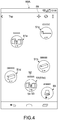
- Fig. 4 and Fig. 5 are each a diagram showing a configuration example of a group state image 50 displayed on the touch panel 35.
- Fig. 3 shows a group state image 50A in which a group is not established
- Fig. 4 shows a group state image 50B in which a group is established.
- the group state image 50 includes icon images 51 of the plurality of reproduction apparatuses 10 connected to the home network 1. On the icon images 51, respective images depending on the kind of the reproduction apparatus are displayed. Icon images 51a to 51d shown in Fig. 4 and Fig. 5 respectively correspond to reproduction apparatuses 10a to 10d shown in Fig. 1 .
- Each icon image 51 includes a text image 52 that represents a name, for example. Accordingly, it is possible to know the correspondence with the actual reproduction apparatus 10 placed in each room. Further, on each icon image 51, a network mark 53 (WiFi mark in this example) that represents the connection form with the portable terminal 30 and an individual communication mark 54 (Bluetooth (registered trademark) mark in this example) are placed. The network mark 53 is actively displayed on the reproduction apparatus 10 connected to the home network 1.
- the group state image 50 includes an icon image 55 of the non-network apparatus 13 that is not connected to the home network 1. Also on the icon image 55, the text image 52, the network mark 53, and the individual communication mark 54 are placed. The individual communication mark 54 is actively displayed on the non-network apparatus 13. Alternatively, information indicating that it is the non-network apparatus 13 may be displayed.
- the non-network apparatus 13 For example, by selecting a plus mark 59 or the like in the group state image 50, detection of the non-network apparatus 13 is performed and the icon image 55 thereof is displayed in the case where it is detected.
- the detection of the non-network apparatus 13 may be automatically performed.
- a group image 56 of a group including the group apparatus is displayed.
- the group image 56 is a circular image, and the icon images 51 of the group apparatuses that belong to the group are displayed on the periphery of the group image 56.
- the reproduction apparatuses 10b and 10d shown in Fig. 1 are detected as the group apparatus, and the icon images 51b and 51e thereof are placed in the periphery of the group image 56.
- the icon image 51 (icon image 51e in this example) of the reproduction apparatus 10 as the master apparatus is emphatically displayed so that the master apparatus can be identified.
- the method of emphatically displaying the icon image 51 is not limited, and the text image 52 is largely displayed, for example, as shown in Fig. 5 . It goes without saying that it is not limited thereto, and an arbitrary display method such as emphasizing the color of the icon image 51 and blinking the icon image 51 may be employed. Note that information indicating that it is the master apparatus may be newly added.
- display of the network mark 54 or the like of the icon image 51 placed in the periphery of the group image 56 may be omitted because it is obvious that it is connected to the home network 1. Note that in the case where a plurality of groups are established, a plurality of group images 56 corresponding to the groups are displayed.
- the method and technology of generating the group state image 50 are not limited, and an arbitrary method and technology may be used.
- device information including the above-mentioned information related to the group constitution and information for generating the group state image 50 is acquired.
- the device information may include the icon image of each reproduction apparatus 10, and the icon image 51 may be used.
- Information on the name or the like is extracted from the device information, and the text image 52 is generated on the basis of the information.
- the icon images 51 is stored on the side of the portable terminal 30, and the optimal icon image 51 may be selected on the basis of the acquired device information.
- the optimal icon image 51 may be selected on the basis of the acquired device information.
- an image or information for generating the group state image 50 such as the icon image 51 may be acquired.
- the design or the like of the icon image 51 or the group image 56 and the layout of the group state image 50 are not limited to those shown in Fig. 4 , Fig. 5 and the like, and may be appropriately set.
- the user 5 is capable of inputting various operations related to the constitution of a group to the group state image 50 displayed on the touch panel 35.
- the image control unit 41 controls the group state image 50 in response to the operation accepted by the touch panel 35.
- the group control unit 42 shown in Fig. 2 transmits a request or instruction depending on the operation to the master apparatus.
- the master apparatus operates in response to the request or the like, and returns the result to the group control unit 42.
- the image control unit 41 controls the group state image 50 on the basis of the information.
- the detection unit 40 may make an inquiry about the group state at predetermined timing (timing after the operation of the master apparatus or the like) or periodically. Then, on the basis of the result of the inquiry, the group state image 50 may be controlled.
- Fig. 6 is a diagram showing a configuration example of a group state image 50C in the case where a first operation is input.
- the first operation is an operation of selecting the icon image 51 of the reproduction apparatus 10 in the group state image 50C by the user 5.
- the image control unit 41 emphatically displays the icon images 51 of the reproduction apparatuses 10 that are capable of constituting the group (the icon 51b, an icon 51c, and the icon 51e in this example), of the icon images 51 in the group state image 50C, in response to the first operation.
- the multi-room-ready apparatus is emphatically displayed.
- the method of emphasizing the icon image 51 is not limited.
- animation in which the size of the icon image 51 of the multi-room-ready apparatus is dynamically changed is displayed.
- the icon image 51 of the multi-room-ready apparatus is enlarged or reduced.
- animation whose color is changed with time or animation in which the icon image blinks may be displayed.
- animation is referred to simply as an image in some cases.
- the icon image 51 of the multi-room-ready apparatus By emphatically displaying the icon image 51 of the multi-room-ready apparatus, it is possible to easily know the multi-room-ready apparatus and perform creation of a group and the like with a good operability. Note that in this embodiment, the icon image 51 of the multi-room-ready apparatus is emphatically displayed even in the case where any one of the icon images 51 in the group state image 50C is selected. Instead of this, the emphatic display of the icon image 51 of the multi-room-ready apparatus may be performed only in the case where the icon image 51 of the multi-room-ready apparatus is selected. Further, in the case where the icon image 55 of the non-network apparatus 13 is selected, the indication thereof may be displayed.
- Fig. 7 is a diagram showing configuration example of a group state image 50D in the case where new creation of a group is input.
- the second operation is an operation of moving the icon image 51 (icon image 51b in this example) of the reproduction apparatus 10 that does not constitute a group (hereinafter, referred to as the non-constitution apparatus) and is the multi-room-ready apparatus in the group state image 50 while selecting the icon image 51.
- the destination of the second operation is the icon image 51e of the multi-room-ready apparatus and the selection is released on the icon image 51e
- the selected non-constitution apparatus and the multi-room-ready apparatus as the destination newly constitute a group
- the group image 56 thereof is displayed.
- the image transits from the group state image 50D shown in Fig. 7 to the group state image 50B.
- an image where two images of the icon image 51b and the icon image 51e are apart from each other by a predetermined distance, an image where the circular shape of the group image 56 expands from a dotted shape to a predetermined size, an image where a color is added to the group image 56, and the like are displayed. Accordingly, it is possible to easily recognize that a group is established. As described above, it is possible to easily create a group only by dragging and dropping the icon image 51 of the non-constitution apparatus that is capable of performing the multi-room reproduction on the icon image 51 of another multi-room-ready apparatus.
- the image control unit 41 may automatically adjust the position or size of each image so that the icon image 51 and the group image 56 do not overlap each other. For example, in the case where a plurality of group images 56 are displayed, the size of the circular shape of each group image 56 is appropriately reduced and displayed. Accordingly, it is possible to simply display the group constitution image 50.
- Fig. 8 is a sequence diagram showing an example of an operation of newly creating a group.
- the group control unit 42 acquires the network state of the reproduction apparatuses A to C as targets of group constitution (Step 201).
- the network state is information that represents the connection state with the home network 1, e.g., information on the network strength. This processing may be performed when the operation of newly creating a group shown in Fig. 7 is input or periodically.
- any one of multi-room-ready apparatuses is set as the master apparatus (Step 202).
- the reproduction apparatus 10 having a higher network strength is set as the master apparatus.
- the method of determining the master apparatus is not limited, and the user may select the master apparatus.
- the group control unit 42 transmits a group creation request to the master apparatus (reproduction apparatus A in this example) (Step 203).
- the request includes an ID of the reproduction apparatus as the slave apparatus (reproduction apparatuses B and C in this example).
- the master apparatus that receives the creation request transmits a request for participating in the group to the reproduction apparatuses B and C as the slave apparatuses (Step 204). Accordingly, the group is established, and the reproduction apparatuses A to C are in the group state (Step 205).
- any one of the reproduction apparatuses 10b and 10e is set as the master apparatus, and the group participation request is transmitted to the other reproduction apparatus 10.
- the touch panel 35 supports the multi-touch operation performed by a plurality of fingers
- two non-constitution apparatuses are moved onto another multi-room-ready apparatus in some cases.
- the participation request is transmitted to the plurality of reproduction apparatuses.
- Fig. 9 and Fig 10 are diagrams showing configuration examples of group state images 50E and 50F, respectively, in the case where an operation of new addition to a group is input.
- the destination of the second operation is the group image 56 of a group that is already established
- the selected non-constitution apparatus and the group apparatus included in the group as the destination newly constitute a group.
- a group image 56' is displayed as the image that represents the group.
- the icon image 51c of the selected non-constitution apparatus and the icon image 51b and the icon image 51e of the group apparatuses included in the group are placed in the periphery of the group image 56'.
- animation may be appropriately displayed with respect to the position of each icon image 51 and the size or color of the circular shape of the group image 56'.
- animation may be appropriately displayed with respect to the position of each icon image 51 and the size or color of the circular shape of the group image 56'.
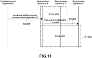
- Fig. 11 is a sequence diagram showing an example of an operation of a new addition to a group.
- the group control unit 42 transmits a request for adding a slave apparatus to the master apparatus (reproduction apparatus A in this example) (Step 301).
- the master apparatus transmits a request for participating in the group to the reproduction apparatus to be added (reproduction apparatus C in this example) on the basis of the ID included in the addition request (Step 302). Accordingly, the reproduction apparatus C is added to the group as the slave apparatus (Step 303).
- the image control unit 42 causes the selected icon image 51 to move to the position. Accordingly, it is possible to cause the icon image 51 to move with a simple operation, and change the positional relationship between the icon images 51.
- the icon images 51 in the group state image 50 in the arrangement relationship similar to the actual position of the reproduction apparatus 10 placed in each room. Accordingly, the user 5 is capable of instinctively knowing the actual position of the reproduction apparatus 10. In addition, it is also possible to arrange the icon images 51 by classifying them for each type of the reproduction apparatus 10 to improve the operability. It goes without saying that it is not limited thereto.
- the image control unit 42 returns the selected icon image 51 to the original position. Accordingly, it is possible to easily know that it cannot constitute a group, for example.
- Fig. 12 to Fig. 14 are diagrams showing configuration examples of group state images 50G, 50H, and 50I, respectively, in the case where an operation of dissolving a group is input.
- the user 5 inputs a third operation.
- the third operation is an operation of moving the icon image 51 of the group apparatus that constitutes a group in the group state image 50 while selecting the icon image 51.
- the position that is away from the group image 56 is typically a position outside of the group image 56.
- the inside or the like of the group image 56 can be the position that is away from the group image 56, depending on the shape or the like of the group image 56.
- the inside of the area is the position that is away from the group image 56.
- Fig. 15 is a sequence diagram showing an example of an operation of dissolving a group.
- the group control unit 42 transmits a request for dissolving a group to the master apparatus (reproduction apparatus A in this example) (Step 401).
- the master apparatus that receives the dissolving request transmits a request for withdrawing from a group to all the slave apparatuses that belong to the group (reproduction apparatuses B and C in this example) (step 402).
- the group is dissolved (Step 403). Note that the dissolving of the group may be performed by another method.
- the icon images 51b and 51c of the slave apparatuses of the group apparatuses are selected, and moved to a position that is away from the group image 56 of the group including the slave apparatuses.
- the withdrawal of the selected slave apparatuses from the group is performed, and the image thereof is displayed (e.g., transition from the group state image 50E in Fig. 9 to the group state image 50B in Fig. 5 ).
- the icon image 51 of the slave apparatus from the group only by dragging and dropping the icon image 51 on the position that is away from the group image 56.
- Fig. 16 is a sequence diagram showing an example of an operation of withdrawing from a group.
- the group control unit 42 transmits a request for withdrawal of the slave apparatus to the master apparatus (reproduction apparatus A in this example) (Step 501).
- the master apparatus transmits the withdrawal request to the reproduction apparatus to be withdrawn (reproduction apparatus C in this example) on the basis of the ID included in the withdrawal request (Step 502). Accordingly, the reproduction apparatus C is withdrawn from the group, and the group constitution including the remaining reproduction apparatuses is left (Step 503).
- the withdrawal represents getting out of the state where it constitutes a group, i.e., the state where the belonging to the group is eliminated.
- the belonging to the group is inevitably eliminated. Therefore, in the present disclosure, the image where the group is dissolved is included in the image where the group apparatus is withdrawn from the group (image where the belonging to the group is eliminated).
- the portable terminal 30 determines whether or not each of the plurality of reproduction apparatuses 10 connected to the home network 1 constitutes a group.
- the group state image 50 including the icon image 51 of each reproduction apparatus 10 is output on the basis of the detection result, and the group state image 50 is controlled in response to the operation performed by the user 5. Accordingly, the user 5 is capable of inputting various operations such as new creation of a group and new addition to a group while watching the group state image 50 on one screen. As a result, it is possible to control reproduction of content with a good operability.
- the operation that can be input to the group state image 50 is not limited to those described above.
- the icon images 51 and 55 of the non-ready apparatus that does not support the multi-room reproduction and the non-network apparatus 13 can be selected and moved to a position where there is no icon image 51 of another reproduction apparatus 10.
- the icon images 51 and 55 are returned to the respective original positions.
- the icon image 51 of the group apparatus is dragged and dropped on the icon image 51 of another group-ready apparatus located at a position that is away from the group image 56, a new group including the group apparatus and the group-ready apparatus as the destination may be established, and the group image 56 thereof may be displayed. Further, in the case where the destination of the icon image 51 of the group apparatus is another group image 56, the group image 56 in which the group apparatus is added to the group may be displayed. In the case where the destination is on the icon images 51 and 55 of the non-ready apparatus and the non-network apparatus 13, the icon image 51 is returned to the periphery of the group image 56 (not withdrawn from the group).
- the group may continue with any one of the remaining slave apparatuses as the master apparatus, and the group image 56 thereof may be displayed.
- various operations can be input.
- Fig. 17 is a diagram showing a configuration example of a group state image 50J in which meta-information related to content is displayed.
- meta-information 60 related to content reproduced by a plurality of group apparatuses included in the same group may be displayed in the group state image 50J.
- a content name 61 and an artist image 62 are displayed as the meta-information.
- content supplied from the server apparatus 20 on the home network 1 is described as an example of content on which the multi-room reproduction is performed.
- content read by the group-ready apparatus via a CD or USB or content acquired by the group-ready apparatus from predetermined service such as the Internet may be reproduced.
- information 63 that represents the acquisition destination of content (location of content) may be displayed.
- the meta-information may be displayed also in the case where normal reproduction that is not the multi-room reproduction is performed.
- the content name 61, the artist image 62, and the acquisition destination (network service on the Internet) information 63 of content reproduced by a non-ready apparatus 10a corresponding to an icon image 51a are displayed.
- the meta-information related to content may be displayed.
- the Internet information is the URL (Uniform Resource Locator) of a website related to content, the link to an SNS (Social Networking Service) related to content, or the like.
- advertisement related to content, TV program information, and the like may be displayed.
- the image control unit 41 may output a reproduction information image when a fourth operation in which the user 5 selects the group image 56 in the group state image 50J is input.
- the reproduction information image is an image including reproduction information related to the multi-room reproduction performed by a plurality of group apparatuses. Specifically, the output of the reproduction information image in addition to the control of the group state image may be performed.
- FIG. 18 and Fig. 19 are each a diagram showing an example of the reproduction information image.
- a reproduction information image 70 shown in Fig. 18 and Fig. 19 includes a reproduction control unit 71 and an information display unit 72.
- the reproduction control unit 71 includes a plurality of control buttons 73 for controlling reproduction of content and a volume adjustment bar 74. By operating the reproduction control unit 71, it is possible to easily control the multi-room reproduction performed by a plurality of group apparatuses.
- reproduction information related to reproduction of content is displayed on the information display unit 72.
- the kind of content on which multi-reproduction can be performed by the selected group is displayed.
- an icon image 75 that represents a home network, CD, or the like is displayed. Accordingly, it is possible to easily know content that can be reproduced for each group.
- information on a file in which content on which the multi-room reproduction can be performed is stored or information on content is displayed in a list.
- information on content on which the multi-room reproduction is being performed is displayed. For example, a content name, an artist image, a reproduction position, and the like are displayed.
- the various kinds of setting include reproduction setting, power source setting, other setting, network setting, and the like.
- the information display unit 72 in part B of Fig. 19 includes pieces of information on items for performing various kinds of setting related to reproduction of content. Examples of the pieces of information on items include sound quality setting, EQ (equalizer) setting, timer setting, and other setting.
- the reproduction information images 70 shown in Fig. 18 and Fig. 19 may be switchably displayed.
- the reproduction information image 70 may be switchable in the order of part A of Fig. 18 , part B of Fig. 18 , and then part C of Fig. 18 .
- the following operation is input, for example.
- any one of the icon images 75 of the content type in part A of Fig. 18 is selected, any one of content items 76 in part B of Fig. 18 is selected, and then, content information in part C of Fig. 18 is displayed.
- the reproduction information image 70 may be switchable in the order of part A of Fig. 18 , part A of Fig. 19 , part B of Fig. 19 , and then, part C of Fig. 19 , for example. At this time, the following operation is input, for example.
- An icon image 77 for setting in part A of Fig. 18 is selected, a sound item 78 in part A of Fig. 19 is selected, an item 79 for EQ setting in part B of Fig. 19 is selected, and then, an equalizer in part C of Fig. 19 is displayed. Note that by selecting a return button 80, it is possible to perform switching in the opposite direction.
- reproduction information image By displaying the reproduction information image as describe above, it is possible to perform reproduction setting for each group, EQ setting, and the like with a simple operation. Specifically, it is possible to collectively perform reproduction setting or the like of a plurality of group apparatuses, and exert a high operability. It goes without saying that an image including information different from that described above may be displayed as the reproduction information image.
- the reproduction information image 70 related to the normal reproduction may be output. It can be said that the reproduction information image is a function image related to the multi-room reproduction or the normal reproduction.
- the above-mentioned group in which the multi-room reproduction is performed is an example of the group related to reproduction of content according to the present technology. Specifically, it is not limited to the multi-room reproduction, and the present technology can be applied to a group in which another reproduction operation or the like can be performed or a group established under another reproduction condition.
- the home network 1 established in a house as an example. It goes without saying that it is not limited thereto, and the present technology can be applied to a local network established in a company, facility, or the like. Further, a local network may be established in buildings apart from each other. For example, a car audio provided in a vehicle is employed as the reproduction apparatus, and the present technology may be applied to the local network to which the car audio is connected. Further, the present technology may be applied on the global network.
- the number of reproduction apparatuses constituting a group is not limited, but the upper limit thereof, e.g., not more than 10, may be set. It goes without saying that the upper limit does not necessarily need to be set.
- a portable terminal has been illustrated as the information processing apparatus according to the present technology.
- the present technology can be executed by an arbitrary computer such as a stationary apparatus.
- the group state image 50 and the like may be displayed on the touch panel of the reproduction apparatus 10 that is capable of operating as a DMP, and various operations may be input thereto.
Abstract
Description
- The present technology relates to an information processing apparatus, an information processing method, and a program for controlling a reproduction apparatus connected to a network.
- A system in which a home network is established in a house and content such as music and video is reproduced by a plurality of AV (Audio & Visual) apparatuses connected thereto has been known. For example, in
Patent Literature 1, a system in which a plurality of AV apparatuses placed in a plurality of rooms are connected to an IEEE (Institute of Electrical and Electronics Engineers) 1394 network is disclosed. In this system, groups are defined corresponding to the rooms in which the AV apparatuses are placed, and the corresponding AV apparatus is displayed for each group on a display screen of an IR (Infrared) remote controller. Accordingly, the selection work of the AV apparatus is made more efficient (e.g., paragraphs 0033 to 0035 of the specification of Patent Literature 1). Citation List - Patent Literature 1: Japanese Patent Application Laid-open No.
2002-199474 - In the above-mentioned system, a technology that is capable of controlling reproduction of content by a plurality of reproduction apparatuses connected to a network with a good operability is desired.
- In view of the circumstances as described above, it is an object of the present technology to provide an information processing apparatus, an information processing method, and a program that are capable of controlling reproduction of content by a plurality of reproduction apparatuses connected to a network with a good operability.
- In order to achieve the above-mentioned object, an information processing apparatus according to an embodiment of the present technology includes a detection unit, an acceptance unit, and an image control unit.
- The detection unit is capable of detecting whether or not each of a plurality of reproduction apparatuses constitutes a group related to reproduction of content, each of the plurality of reproduction apparatuses being connected to a network, each of the plurality of reproduction apparatuses being capable of reproducing the content.
- The acceptance unit accepts a user operation related to constitution of the group.
- The image control unit outputs a group state image on the basis of a detection result by the detection unit, the group state image representing a constitution state of the group, the group state image including an image of each of the plurality of reproduction apparatuses, and controls the group state image in response to the accepted user operation related to constitution of the group.
- In this information processing apparatus, whether or not each of a plurality of reproduction apparatuses connected to a network constitutes a group is detected. A group state image including an image of each of the plurality of reproduction apparatuses is output on the basis of a detection result, and the group state image is controlled in response to a user operation. Accordingly, the user is capable of controlling reproduction of content with a good operability while watching the group state image.
- The image control unit may display, when a reproduction apparatus constituting the group is detected, an image of the group including the reproduction apparatus in the group state image.
- Accordingly, it is possible to easily know whether or not a group is established at present.
- The group may be a group that is capable of reproducing the same content at the same time.
- By using the present technology, it is possible to control simultaneous reproduction of content by the group with a good operability.
- The acceptance unit may accept a first operation of selecting an image of one of the plurality of reproduction apparatuses. In this case, the image control unit may emphatically display an image of a reproduction apparatus that is capable of constituting the group, in response to the first operation.
- Accordingly, it is possible to easily know an apparatus that is capable of constituting a group and perform creation of a group and the like with a good operability.
- The acceptance unit may accept a second operation of causing an image of a non-constitution apparatus that is capable of constituting the group to move in the group state image while selecting the image of the non-constitution apparatus, the non-constitution apparatus being a reproduction apparatus that does not constitute the group. In this case, the image control unit may display, when a destination of the second operation is an image of the reproduction apparatus that is capable of constituting the group, an image of a group that is newly constituted of the selected non-constitution apparatus and the reproduction apparatus as the destination.
- Accordingly, it is possible to create a group with a simple operation.
- The image control unit may display, when a destination of the second operation is an image of a group that is already established, an image of a group that is newly constituted of the selected non-constitution apparatus and the reproduction apparatus included in the group as the destination.
- Accordingly, it is possible to add the non-constitution apparatus to a group with a simple operation.
- The image control unit may cause, when a destination of the second operation is a position where there is no image of another reproduction apparatus, an image of the selected non-constitution apparatus to move to the position.
- Accordingly, it is possible to cause a reproduction apparatus to move in the group state image with a simple operation.
- The image control unit may return, when a destination of the second operation is an image of a reproduction apparatus that is not capable of constituting the group, an image of the selected non-constitution apparatus to its original position.
- Accordingly, it is possible to easily know that a group cannot be created and the like, and improve the operability.
- The acceptance unit may accept a third operation of causing an image of a group apparatus to move in the group state image while selecting the image of the group apparatus, the group apparatus being a reproduction apparatus that constitutes the group. In this case, the image control unit may display, when a destination of the third operation is a positon that is away from an image of the group including the selected group apparatus, an image where the group apparatus is withdrawn from the group.
- Accordingly, it is possible to cause the group apparatus to withdraw from the group with a simple operation.
- The image control unit may identifiably display one of a plurality of group apparatuses included in the group as a master apparatus, and display, when an image of the master apparatus is selected and moved to the position that is away from the image of the group by the third operation, an image where the group is dissolved.
- Accordingly, it is possible to dissolve the group with a simple operation.
- The acceptance unit may accept a fourth operation of selecting an image of the group. In this case, the image control unit may output a reproduction information image including information related to reproduction of the content by a plurality of group apparatuses included in the group, in response to the fourth operation.
- Accordingly, it is possible to perform reproduction setting and the like for each group with a simple operation.
- The reproduction information image may include information on content that the plurality of group apparatuses are capable of reproducing at the same time.
- Accordingly, it is easily know content that can be reproduced for each group.
- The image control unit may display meta-information related to content that is being reproduced by the plurality of group apparatuses in the group state image.
- Accordingly, it is possible to know information of content.
- The acceptance unit may be a touch panel. In this case, the group state image may be displayed on the touch panel.
- It is possible to control reproduction of content with a good operability by using the touch panel.
- An information processing method according to an embodiment of the present technology includes detecting whether or not each of a plurality of reproduction apparatuses constitutes a group related to reproduction of content, each of the plurality of reproduction apparatuses being connected to a network, each of the plurality of reproduction apparatuses being capable of reproducing the content.
- A user operation related to constitution of the group is accepted.
- A group state image is controlled on the basis of a detection result by the detection unit, the group state image representing a constitution state of the group, the group state image including an image of each of the plurality of reproduction apparatuses, and controlling the group state image in response to the accepted user operation related to constitution of the group.
- A program according to an embodiment of the present technology causes a computer to execute the following steps of:
- detecting whether or not each of a plurality of reproduction apparatuses constitutes a group related to reproduction of content, each of the plurality of reproduction apparatuses being connected to a network, each of the plurality of reproduction apparatuses being capable of reproducing the content;
- accepting a user operation related to constitution of the group; and
- outputting a group state image on the basis of a detection result by the detection unit, the group state image representing a constitution state of the group, the group state image including an image of each of the plurality of reproduction apparatuses, and controlling the group state image in response to the accepted user operation related to constitution of the group. Advantageous Effects of Invention
- As described above, in accordance with the present technology, it is possible to control reproduction of content by a plurality of reproduction apparatuses connected to a network with a good operability. It should be noted that the effect described here is not necessarily limitative and may be any effect described in the present disclosure.
-
- [
Fig. 1 ] A schematic diagram showing a configuration example of a network system according to an embodiment. - [
Fig. 2 ] A block diagram showing a configuration example of the portable terminal shown inFig. 1 . - [
Fig. 3 ] A sequence diagram showing an operational example to when a group state image is output. - [
Fig. 4 ] A diagram showing a configuration example of the group state image in the case where a group is not established. - [
Fig. 5 ] A diagram showing a configuration example of the group state image in the case where a group is established. - [
Fig. 6 ] A diagram showing a configuration example of the group state image in the case where a first operation is input. - [
Fig. 7 ] A diagram showing a configuration example of the group state image in the case where a group is newly created. - [
Fig. 8 ] A sequence diagram showing an example of an operation of newly creating a group. - [
Fig. 9 ] A diagram showing a configuration example of the group state image in the case where an operation of a new addition to a group is input. - [
Fig. 10 ] A diagram showing a configuration example of the group state image in the case where an operation of a new addition to a group is input. - [
Fig. 11 ] A sequence diagram showing an example of an operation of a new addition to a group. - [
Fig. 12 ] A diagram showing a configuration example of the group state image in the case where an operation of dissolving a group is input. - [
Fig. 13 ] A diagram showing a configuration example of the group state image in the case where an operation of dissolving a group is input. - [
Fig. 14 ] A diagram showing a configuration example of the group state image in the case where an operation of dissolving a group is input. - [
Fig. 15 ] A sequence diagram showing an example of an operation of dissolving a group. - [
Fig. 16 ] A sequence diagram showing an example of an operation of withdrawing from a group. - [
Fig. 17 ] A diagram showing a configuration example of the group state image on which meta-information related to content is displayed. - [
Fig. 18 ] A diagram showing an example of a reproduction information image. - [
Fig. 19 ] A diagram showing an example of a reproduction information image. - Hereinafter, embodiments according to the present technology will be described with reference to the drawings.
-
Fig. 1 is a schematic diagram showing a configuration example of a network system according to an embodiment of the present technology. Anetwork system 500 includes ahome network 1 established in a house, a plurality ofreproduction apparatuses 10 connected thereto, aserver apparatus 20 that provides content, and aportable terminal 30 that functions as an information processing apparatus according to this embodiment. - As the
home network 1, for example, a network conforming to the DLNA (Digital Living Network Alliance) standard is used. In this case, the plurality ofreproduction apparatuses 10 each function as a DMR (Digital Media Renderer), and theserver apparatus 20 functions as a DMS (Digital Media Server). Further, the portable terminal 30 functions as a DMC (Digital Media Controller). However, it is not limited to this configuration, and a network using another protocol may be used, for example. - The plurality of
reproduction apparatuses 10, theserver apparatus 20, and theportable terminal 30 are connected to thehome network 1 via, for example, an access point (not shown) through wireless communication such as WiFi. However, the method of connecting to thehome network 1 is not limited, and wired communication via a LAN cable or the like may be used. - As shown in
Fig. 1 , the plurality ofreproduction apparatuses 10 are placed in rooms of aliving room 2, ahobby room 3, and a bed room 4. By operating theportable terminal 30, auser 5 is capable of instructing therespective reproduction apparatuses 10 placed in the rooms to reproduce content in theserver apparatus 20. In this embodiment, music content is reproduced by the plurality ofreproduction apparatuses 10. However, the present technology is not limited to the reproduction of music content, and can be applied to reproduction of various kinds of content such as video. Note that the number ofreproduction apparatuses 10 is not limited. - As each of the
reproduction apparatuses 10, one that is capable of operating as a DMP (Digital Media Player) may be placed. In this case, by operating a UI (User Interface) of therespective reproduction apparatuses 10, it is possible to reproduce content in theserver apparatus 20. - As each of the
reproduction apparatuses 10, for example, a television receiver, a PC (Personal computer), an audio video receiver, a video monitor, a home video game machine, or the like is used. As theserver apparatus 20, for example, a PC, a network-ready HDD (NAS) or the like is used. As theportable terminal 30, typically, a smartphone is used. However, it is not limited thereto, and various PDAs (Personal Digital Assistant) such as a tablet terminal and a game machine. - Note that in this embodiment, a reproduction apparatus that is not connected to the home network 1 (hereinafter, referred to as non-network apparatus) 13 is placed in the bed room 4 in
Fig. 1 . Thenon-network apparatus 13 does not function as a DMR, and reproduces a CD, content read via a USB (Universal Serial Bus), or content acquired from another global network or the like. In this embodiment, it is possible to control the operation of thenon-network apparatus 13 by theportable terminal 30 through near field communication such as Bluetooth (registered trademark). -
Fig. 2 is a block diagram showing a configuration example of theportable terminal 30. Theportable terminal 30 includes a CPU (Central Processing Unit) 31, a ROM (Read Only Memory) 32, a RAM (Random Access Memory) 33, adisplay 34, and atouch panel 35. Further, theportable terminal 30 includes acommunication unit 36, an external I/F (interface) 37, a key/switch 38, and animaging unit 39. - The
CPU 31 exchanges signals with respective blocks of theportable terminal 30 to perform various kinds of operations, and collectively controls various kinds of processing performed in theportable terminal 30 such as instruction for thereproduction apparatuses 10 to reproduce content and display of an image on the display 34 (the touch panel 35). - The
ROM 32 stores various kinds of data processed by theCPU 31 such as various kinds of image data and metadata, and various programs such as an application. TheRAM 32 is used as a working area of theCPU 31. When a program such as an application is executed, various kinds of data necessary for the execution are loaded into theRAM 32. - Instead or in addition to the
ROM 32, an HDD (Hard Disk Drive), a flash memory, or another nonvolatile memory such as a solid-state memory may be provided. Then, in these storage devices, the above-mentioned various kinds of data or programs may be stored. - The
display 34 is a display device using a liquid crystal, an EL (Electro-Luminescence), or the like. As shown inFig. 2 , thedisplay 34 is integrally formed with thetouch panel 35. Therefore, various GUIs (Graphical User Interface) are displayed on thetouch panel 35, and a touch operation can be input with respect to the GUI. Thetouch panel 35 functions as an acceptance unit in this embodiment. - The
communication unit 36 is an interface for connecting theportable terminal 30 to thehome network 1 or thenon-network apparatus 13. For example, as thecommunication unit 36, a wireless LAN module such as WiFi or short-distance wireless module such as Bluetooth (registered trademark) is provided. - The external I/
F 37 is an interface for connecting to an external apparatus on the basis of the standards such as a USB and an HDMI (registered trademark) (High-Definition Multimedia Interface). In addition, an interface for connecting to various memory cards such as a memory stick may be configured. - The
key switch unit 38 accepts, particularly, an operation performed by theuser 5, which cannot be input via thetouch panel 35, such as a power supply switch and a short cut key. Theimaging unit 39 includes, for example, a CMOS (Complementary Metal Oxide Semiconductor) or CCD (Charge Coupled Devices) sensor, and generates a digital image of an object. - The information processing performed by the
portable terminal 30 having the above-mentioned hardware configuration is achieved by cooperation of software stored in theROM 32 or the like and a hardware resource of theportable terminal 30. For example, by theCPU 31 loading the program (application) according to the present technology stored in theROM 32 or the like into theRAM 33 to execute it, the information processing method according to the present technology is achieved. At this time, as shown inFig. 2 , theCPU 31 functions as adetection unit 40, animage control unit 41, and agroup control unit 42. In order to achieve these blocks, dedicated hardware may be appropriately used. - The program such as an application is installed in the portable terminal 30 from, for example, a global network. Alternatively, the program may be installed in the
portable terminal 30 via a recording medium. - As the operation of the
portable terminal 30 according to this embodiment, multi-room reproduction of content will be described. The multi-room reproduction is a reproduction method in which a group is constituted of two ormore reproduction apparatuses 10 connected to thehome network 1 and the group simultaneously reproduces the same content. - For example, by causing the plurality of
reproduction apparatuses 10 in the same room to reproduce the same content, it is possible to enjoy music in the entire room at a high volume. Alternatively, for example, in the case where many friends are invited and a party is held, it is possible to liven up the party by causing thereproduction apparatuses 10 placed in the rooms to reproduce the same content and simultaneously controlling the operations. - In this embodiment, one of the two or
more reproduction apparatuses 10 constituting the group is set as a master apparatus, andother reproduction apparatuses 10 are set as slave apparatuses. When the multi-room reproduction is performed, the instruction is transmitted to the master apparatus. The master apparatus downloads content from theserver apparatus 20, and simultaneously performs streaming distribution on the slave apparatus. Accordingly, the multi-room reproduction of content is achieved. Note that the method of achieving the multi-room reproduction is not limited, and an arbitrary technology related to, for example, synchronous reproduction, may be appropriately used. - In the present technology, as will be described later, the current constitution state of the group is perspectively displayed on the
touch panel 35 of theportable terminal 30. Then, on the basis of the image, it is possible to newly create a group, dissolve the group, make a new addition to the group, or withdraw from the group with a good operability. Therefore, it is possible to control the multi-room reproduction of content with a good operability. -
Fig. 3 is a sequence diagram showing an operational example to when a group state image showing the constitution state of a group is output. InFig. 3 , as the reproduction apparatus connected to thehome network 1, three reproduction apparatuses A to C are shown, in order to make the figure simple. - When an application is activated by the
user 5, thedetection unit 40 of theportable terminal 30 generates a search request for finding thereproduction apparatus 10, and the search request is transmitted on thehome network 1 by broadcast (Step 101). The reproduction apparatuses A to C each transmit a response to the search request to the portable terminal 30 (Step 102). The response includes information that represents whether or not it is a multi-room-ready apparatus. - The multi-room-ready apparatus is the
reproduction apparatus 10 that is capable of constituting a group and performing the multi-room reproduction. Thereproduction apparatus 10 that cannot perform the multi-room reproduction is a non-ready apparatus. Specifically, in Step 102, information on whether or not it is capable of constituting a group is transmitted to theportable terminal 30. - The
detection unit 40 makes an inquiry about the group state to the multi-room-ready apparatus (reproduction apparatuses A to C in this example) (Step 103). The group state is information that represents whether or not it constitutes a group or it is a master apparatus or slave apparatus in the case where it constitutes a group. - With the search request in Step 101 and the inquiry about the group state in Step 103, the
detection unit 40 of theportable terminal 30 is capable of detecting whether or not each of the plurality ofreproduction apparatuses 10 that are connected to thehome network 1 and capable of reproducing content constitutes a group for the multi-room reproduction. Note that a control message or the like of, for example, UPnP (Universal Plug and Play) for this detection is transmitted on thehome network 1. It goes without saying that it is not limited thereto, and another arbitrary technology may be used to perform the detection. - The
detection unit 40 makes an inquiry about checking a list of the group apparatus to the master apparatus (reproduction apparatus A in this example) (In Step 104). The group apparatus is thereproduction apparatus 10 constituting a group. The master apparatus transmits a list of the slave apparatus that belongs to the group in response to the inquiry (Step 105). - The
detection unit 40 is capable of determining the current group constitution state on the basis of the acquired information. Theimage control unit 41 outputs a group state image on the basis of the determination result. Note that a unique ID is set on each reproduction apparatus, and thus, the reproduction apparatus can be identified. -
Fig. 4 andFig. 5 are each a diagram showing a configuration example of a group state image 50 displayed on thetouch panel 35.Fig. 3 shows agroup state image 50A in which a group is not established, andFig. 4 shows agroup state image 50B in which a group is established. - As shown in
Fig. 4 andFig. 5 , the group state image 50 includesicon images 51 of the plurality ofreproduction apparatuses 10 connected to thehome network 1. On theicon images 51, respective images depending on the kind of the reproduction apparatus are displayed.Icon images 51a to 51d shown inFig. 4 andFig. 5 respectively correspond toreproduction apparatuses 10a to 10d shown inFig. 1 . - Each
icon image 51 includes atext image 52 that represents a name, for example. Accordingly, it is possible to know the correspondence with theactual reproduction apparatus 10 placed in each room. Further, on eachicon image 51, a network mark 53 (WiFi mark in this example) that represents the connection form with theportable terminal 30 and an individual communication mark 54 (Bluetooth (registered trademark) mark in this example) are placed. Thenetwork mark 53 is actively displayed on thereproduction apparatus 10 connected to thehome network 1. - The group state image 50 includes an
icon image 55 of thenon-network apparatus 13 that is not connected to thehome network 1. Also on theicon image 55, thetext image 52, thenetwork mark 53, and theindividual communication mark 54 are placed. Theindividual communication mark 54 is actively displayed on thenon-network apparatus 13. Alternatively, information indicating that it is thenon-network apparatus 13 may be displayed. - For example, by selecting a
plus mark 59 or the like in the group state image 50, detection of thenon-network apparatus 13 is performed and theicon image 55 thereof is displayed in the case where it is detected. The detection of thenon-network apparatus 13 may be automatically performed. - In this embodiment, it is possible to collectively display the
reproduction apparatuses touch panel 35. Accordingly, it is possible to control reproduction of content with a good operability. Note that thenon-network apparatus 13 cannot perform the multi-room reproduction. - As shown in
Fig. 5 , in the case where a group is already established, i.e., a group apparatus is detected, agroup image 56 of a group including the group apparatus is displayed. Thegroup image 56 is a circular image, and theicon images 51 of the group apparatuses that belong to the group are displayed on the periphery of thegroup image 56. In the example shown inFig. 5 , thereproduction apparatuses Fig. 1 are detected as the group apparatus, and theicon images group image 56. - When the
group image 56 is displayed, the icon image 51 (icon image 51e in this example) of thereproduction apparatus 10 as the master apparatus is emphatically displayed so that the master apparatus can be identified. The method of emphatically displaying theicon image 51 is not limited, and thetext image 52 is largely displayed, for example, as shown inFig. 5 . It goes without saying that it is not limited thereto, and an arbitrary display method such as emphasizing the color of theicon image 51 and blinking theicon image 51 may be employed. Note that information indicating that it is the master apparatus may be newly added. - As shown in
Fig. 5 , display of thenetwork mark 54 or the like of theicon image 51 placed in the periphery of thegroup image 56 may be omitted because it is obvious that it is connected to thehome network 1. Note that in the case where a plurality of groups are established, a plurality ofgroup images 56 corresponding to the groups are displayed. - The method and technology of generating the group state image 50 are not limited, and an arbitrary method and technology may be used. For example, in Steps 102, 103, or the like in
Fig. 3 , device information including the above-mentioned information related to the group constitution and information for generating the group state image 50 is acquired. The device information may include the icon image of eachreproduction apparatus 10, and theicon image 51 may be used. Information on the name or the like is extracted from the device information, and thetext image 52 is generated on the basis of the information. - Alternatively, the
icon images 51 is stored on the side of theportable terminal 30, and theoptimal icon image 51 may be selected on the basis of the acquired device information. Alternatively, via a global network such as the Internet, an image or information for generating the group state image 50 such as theicon image 51 may be acquired. - The design or the like of the
icon image 51 or thegroup image 56 and the layout of the group state image 50 are not limited to those shown inFig. 4 ,Fig. 5 and the like, and may be appropriately set. - The
user 5 is capable of inputting various operations related to the constitution of a group to the group state image 50 displayed on thetouch panel 35. Theimage control unit 41 controls the group state image 50 in response to the operation accepted by thetouch panel 35. - For example, in the case where an operation of newly creating a group, making new addition, or the like is input, the
group control unit 42 shown inFig. 2 transmits a request or instruction depending on the operation to the master apparatus. The master apparatus operates in response to the request or the like, and returns the result to thegroup control unit 42. Theimage control unit 41 controls the group state image 50 on the basis of the information. - The
detection unit 40 may make an inquiry about the group state at predetermined timing (timing after the operation of the master apparatus or the like) or periodically. Then, on the basis of the result of the inquiry, the group state image 50 may be controlled. -
Fig. 6 is a diagram showing a configuration example of agroup state image 50C in the case where a first operation is input. The first operation is an operation of selecting theicon image 51 of thereproduction apparatus 10 in thegroup state image 50C by theuser 5. Theimage control unit 41 emphatically displays theicon images 51 of thereproduction apparatuses 10 that are capable of constituting the group (theicon 51b, anicon 51c, and theicon 51e in this example), of theicon images 51 in thegroup state image 50C, in response to the first operation. Specifically, the multi-room-ready apparatus is emphatically displayed. - The method of emphasizing the
icon image 51 is not limited. In this embodiment, while theuser 5 selects theicon image 51, animation in which the size of theicon image 51 of the multi-room-ready apparatus is dynamically changed is displayed. Specifically, theicon image 51 of the multi-room-ready apparatus is enlarged or reduced. Alternatively, animation whose color is changed with time or animation in which the icon image blinks may be displayed. Hereinafter, animation is referred to simply as an image in some cases. - By emphatically displaying the
icon image 51 of the multi-room-ready apparatus, it is possible to easily know the multi-room-ready apparatus and perform creation of a group and the like with a good operability. Note that in this embodiment, theicon image 51 of the multi-room-ready apparatus is emphatically displayed even in the case where any one of theicon images 51 in thegroup state image 50C is selected. Instead of this, the emphatic display of theicon image 51 of the multi-room-ready apparatus may be performed only in the case where theicon image 51 of the multi-room-ready apparatus is selected. Further, in the case where theicon image 55 of thenon-network apparatus 13 is selected, the indication thereof may be displayed. -
Fig. 7 is a diagram showing configuration example of agroup state image 50D in the case where new creation of a group is input. When a group is newly created, theuser 5 inputs a second operation. The second operation is an operation of moving the icon image 51 (icon image 51b in this example) of thereproduction apparatus 10 that does not constitute a group (hereinafter, referred to as the non-constitution apparatus) and is the multi-room-ready apparatus in the group state image 50 while selecting theicon image 51. - As shown in
Fig. 7 , in the case where the destination of the second operation is theicon image 51e of the multi-room-ready apparatus and the selection is released on theicon image 51e, the selected non-constitution apparatus and the multi-room-ready apparatus as the destination newly constitute a group, and thegroup image 56 thereof is displayed. As a result, the image transits from thegroup state image 50D shown inFig. 7 to thegroup state image 50B. - At this time, for example, an image where two images of the
icon image 51b and theicon image 51e are apart from each other by a predetermined distance, an image where the circular shape of thegroup image 56 expands from a dotted shape to a predetermined size, an image where a color is added to thegroup image 56, and the like are displayed. Accordingly, it is possible to easily recognize that a group is established. As described above, it is possible to easily create a group only by dragging and dropping theicon image 51 of the non-constitution apparatus that is capable of performing the multi-room reproduction on theicon image 51 of another multi-room-ready apparatus. - Note that the
image control unit 41 may automatically adjust the position or size of each image so that theicon image 51 and thegroup image 56 do not overlap each other. For example, in the case where a plurality ofgroup images 56 are displayed, the size of the circular shape of eachgroup image 56 is appropriately reduced and displayed. Accordingly, it is possible to simply display the group constitution image 50. -
Fig. 8 is a sequence diagram showing an example of an operation of newly creating a group. Thegroup control unit 42 acquires the network state of the reproduction apparatuses A to C as targets of group constitution (Step 201). The network state is information that represents the connection state with thehome network 1, e.g., information on the network strength. This processing may be performed when the operation of newly creating a group shown inFig. 7 is input or periodically. - On the basis of the acquired information on the network state, any one of multi-room-ready apparatuses is set as the master apparatus (Step 202). For example, the
reproduction apparatus 10 having a higher network strength is set as the master apparatus. The method of determining the master apparatus is not limited, and the user may select the master apparatus. - The
group control unit 42 transmits a group creation request to the master apparatus (reproduction apparatus A in this example) (Step 203). The request includes an ID of the reproduction apparatus as the slave apparatus (reproduction apparatuses B and C in this example). The master apparatus that receives the creation request transmits a request for participating in the group to the reproduction apparatuses B and C as the slave apparatuses (Step 204). Accordingly, the group is established, and the reproduction apparatuses A to C are in the group state (Step 205). - Note that in the example shown in
Fig. 8 , there are a plurality of reproduction apparatuses as the slave apparatuses. It goes without saying that in the case where the operation shown inFig. 7 is input, any one of thereproduction apparatuses other reproduction apparatus 10. In the case where thetouch panel 35 supports the multi-touch operation performed by a plurality of fingers, two non-constitution apparatuses are moved onto another multi-room-ready apparatus in some cases. In this case, as shown inFig. 8 , the participation request is transmitted to the plurality of reproduction apparatuses. -
Fig. 9 andFig 10 are diagrams showing configuration examples ofgroup state images Fig. 9 , in the case where the destination of the second operation is thegroup image 56 of a group that is already established, the selected non-constitution apparatus and the group apparatus included in the group as the destination newly constitute a group. Then, as shown inFig. 10 , a group image 56' is displayed as the image that represents the group. Theicon image 51c of the selected non-constitution apparatus and theicon image 51b and theicon image 51e of the group apparatuses included in the group are placed in the periphery of the group image 56'. - At this time, animation may be appropriately displayed with respect to the position of each
icon image 51 and the size or color of the circular shape of the group image 56'. As described above, only by dragging and dropping the multi-room-ready non-constitution apparatus on thegroup image 56, it is possible to easily make a new addition to the group. -
Fig. 11 is a sequence diagram showing an example of an operation of a new addition to a group. Thegroup control unit 42 transmits a request for adding a slave apparatus to the master apparatus (reproduction apparatus A in this example) (Step 301). The master apparatus transmits a request for participating in the group to the reproduction apparatus to be added (reproduction apparatus C in this example) on the basis of the ID included in the addition request (Step 302). Accordingly, the reproduction apparatus C is added to the group as the slave apparatus (Step 303). - In the case where the destination of the second operation is a position where there is no
icon image 51 of another reproduction apparatus in the group state image 50, theimage control unit 42 causes the selectedicon image 51 to move to the position. Accordingly, it is possible to cause theicon image 51 to move with a simple operation, and change the positional relationship between theicon images 51. - For example, it is possible to easily arrange the
icon images 51 in the group state image 50 in the arrangement relationship similar to the actual position of thereproduction apparatus 10 placed in each room. Accordingly, theuser 5 is capable of instinctively knowing the actual position of thereproduction apparatus 10. In addition, it is also possible to arrange theicon images 51 by classifying them for each type of thereproduction apparatus 10 to improve the operability. It goes without saying that it is not limited thereto. - In the case where the destination of the second operation is on the
icon images non-network apparatus 13, theimage control unit 42 returns the selectedicon image 51 to the original position. Accordingly, it is possible to easily know that it cannot constitute a group, for example. -
Fig. 12 to Fig. 14 are diagrams showing configuration examples ofgroup state images user 5 inputs a third operation. The third operation is an operation of moving theicon image 51 of the group apparatus that constitutes a group in the group state image 50 while selecting theicon image 51. - As shown in
Fig. 12 andFig. 13 , assumption is made that theicon image 51e of the master apparatus is selected, and moved to a position that is away from thegroup image 56 of the group including the master apparatus. As a result, the group is dissolved, and thegroup image 56 is deleted as shown inFig. 14 . Further, theicon image 51e of the reproduction apparatus that has been the master apparatus is moved to the position where the selection is released. - As described above, only by dragging and dropping the
icon image 51 of the master apparatus on a position that is away from thegroup image 56, it is possible to simply dissolve the group. Note that as the image where the group is dissolved, an arbitrary image may be displayed as long as the indication of the dissolving can be understood. Further, the indication that the group is dissolved may be displayed by a text image or the like. - The position that is away from the
group image 56 is typically a position outside of thegroup image 56. However, it is not limited thereto, and the inside or the like of thegroup image 56 can be the position that is away from thegroup image 56, depending on the shape or the like of thegroup image 56. Further, in the case where a predetermined area in the group state image 50 is defined as a group withdrawal area or dissolving area, the inside of the area is the position that is away from thegroup image 56. -
Fig. 15 is a sequence diagram showing an example of an operation of dissolving a group. Thegroup control unit 42 transmits a request for dissolving a group to the master apparatus (reproduction apparatus A in this example) (Step 401). The master apparatus that receives the dissolving request transmits a request for withdrawing from a group to all the slave apparatuses that belong to the group (reproduction apparatuses B and C in this example) (step 402). When all the slave apparatuses are withdrawn, the group is dissolved (Step 403). Note that the dissolving of the group may be performed by another method. - Assumption is made that the
icon images group image 56 of the group including the slave apparatuses. In this case, the withdrawal of the selected slave apparatuses from the group is performed, and the image thereof is displayed (e.g., transition from thegroup state image 50E inFig. 9 to thegroup state image 50B inFig. 5 ). As described above, it is possible to easily withdraw theicon image 51 of the slave apparatus from the group only by dragging and dropping theicon image 51 on the position that is away from thegroup image 56. -
Fig. 16 is a sequence diagram showing an example of an operation of withdrawing from a group. Thegroup control unit 42 transmits a request for withdrawal of the slave apparatus to the master apparatus (reproduction apparatus A in this example) (Step 501). The master apparatus transmits the withdrawal request to the reproduction apparatus to be withdrawn (reproduction apparatus C in this example) on the basis of the ID included in the withdrawal request (Step 502). Accordingly, the reproduction apparatus C is withdrawn from the group, and the group constitution including the remaining reproduction apparatuses is left (Step 503). - Note that in the present disclosure, the withdrawal represents getting out of the state where it constitutes a group, i.e., the state where the belonging to the group is eliminated. When the group is dissolved, the belonging to the group is inevitably eliminated. Therefore, in the present disclosure, the image where the group is dissolved is included in the image where the group apparatus is withdrawn from the group (image where the belonging to the group is eliminated).
- As described above, in the
portable terminal 30 according to this embodiment, whether or not each of the plurality ofreproduction apparatuses 10 connected to thehome network 1 constitutes a group is detected. The group state image 50 including theicon image 51 of eachreproduction apparatus 10 is output on the basis of the detection result, and the group state image 50 is controlled in response to the operation performed by theuser 5. Accordingly, theuser 5 is capable of inputting various operations such as new creation of a group and new addition to a group while watching the group state image 50 on one screen. As a result, it is possible to control reproduction of content with a good operability. - The operation that can be input to the group state image 50 is not limited to those described above. For example, the
icon images non-network apparatus 13 can be selected and moved to a position where there is noicon image 51 of anotherreproduction apparatus 10. In the case where the destination is on anotherreproduction apparatus 10, theicon images - In the case where the
icon image 51 of the group apparatus is dragged and dropped on theicon image 51 of another group-ready apparatus located at a position that is away from thegroup image 56, a new group including the group apparatus and the group-ready apparatus as the destination may be established, and thegroup image 56 thereof may be displayed. Further, in the case where the destination of theicon image 51 of the group apparatus is anothergroup image 56, thegroup image 56 in which the group apparatus is added to the group may be displayed. In the case where the destination is on theicon images non-network apparatus 13, theicon image 51 is returned to the periphery of the group image 56 (not withdrawn from the group). - Further, in the case where the
icon image 51 of the master apparatus is moved to a position that is away from thegroup image 56, the group does not necessarily need to be dissolved, the group may continue with any one of the remaining slave apparatuses as the master apparatus, and thegroup image 56 thereof may be displayed. In addition, various operations can be input. - The present technology is not limited to the embodiment described above, and other various embodiments can be achieved.
-
Fig. 17 is a diagram showing a configuration example of agroup state image 50J in which meta-information related to content is displayed. For example, meta-information 60 related to content reproduced by a plurality of group apparatuses included in the same group may be displayed in thegroup state image 50J. In the example shown inFig. 17 , acontent name 61 and an artist image 62 are displayed as the meta-information. However, it is not limited thereto. - For example, in the above-mentioned embodiment, content supplied from the
server apparatus 20 on thehome network 1 is described as an example of content on which the multi-room reproduction is performed. However, it is not limited thereto, and content read by the group-ready apparatus via a CD or USB or content acquired by the group-ready apparatus from predetermined service such as the Internet may be reproduced. In such a case, as the meta-information 60,information 63 that represents the acquisition destination of content (location of content) may be displayed. - Note that the meta-information may be displayed also in the case where normal reproduction that is not the multi-room reproduction is performed. In
Fig. 17 , thecontent name 61, the artist image 62, and the acquisition destination (network service on the Internet)information 63 of content reproduced by anon-ready apparatus 10a corresponding to anicon image 51a are displayed. - In addition, as the meta-information related to content, Internet information related to content may be displayed. The Internet information is the URL (Uniform Resource Locator) of a website related to content, the link to an SNS (Social Networking Service) related to content, or the like. Further, advertisement related to content, TV program information, and the like may be displayed. By display the meta-information, it is possible to acquire detailed information related to content and enjoy the reproduction of content more.
- Further, as shown in
Fig. 17 , theimage control unit 41 may output a reproduction information image when a fourth operation in which theuser 5 selects thegroup image 56 in thegroup state image 50J is input. The reproduction information image is an image including reproduction information related to the multi-room reproduction performed by a plurality of group apparatuses. Specifically, the output of the reproduction information image in addition to the control of the group state image may be performed. -
Fig. 18 andFig. 19 are each a diagram showing an example of the reproduction information image. Areproduction information image 70 shown inFig. 18 andFig. 19 includes areproduction control unit 71 and aninformation display unit 72. Thereproduction control unit 71 includes a plurality ofcontrol buttons 73 for controlling reproduction of content and avolume adjustment bar 74. By operating thereproduction control unit 71, it is possible to easily control the multi-room reproduction performed by a plurality of group apparatuses. - On the
information display unit 72, reproduction information related to reproduction of content is displayed. On theinformation display unit 72 in part A ofFig. 18 , the kind of content on which multi-reproduction can be performed by the selected group is displayed. For example, anicon image 75 that represents a home network, CD, or the like is displayed. Accordingly, it is possible to easily know content that can be reproduced for each group. - On the
information display unit 72 in part B ofFig. 18 , information on a file in which content on which the multi-room reproduction can be performed is stored or information on content is displayed in a list. On theinformation display unit 72 in part C ofFig. 18 , information on content on which the multi-room reproduction is being performed is displayed. For example, a content name, an artist image, a reproduction position, and the like are displayed. - On the
information display unit 72 in part A ofFig. 19 , pieces of information on items for performing various kinds of setting are displayed in a list. The various kinds of setting include reproduction setting, power source setting, other setting, network setting, and the like. Theinformation display unit 72 in part B ofFig. 19 includes pieces of information on items for performing various kinds of setting related to reproduction of content. Examples of the pieces of information on items include sound quality setting, EQ (equalizer) setting, timer setting, and other setting. On theinformation display unit 72 in part C ofFig. 19 , an equalizer for EQ setting is displayed. - The
reproduction information images 70 shown inFig. 18 andFig. 19 may be switchably displayed. For example, thereproduction information image 70 may be switchable in the order of part A ofFig. 18 , part B ofFig. 18 , and then part C ofFig. 18 . At this time, the following operation is input, for example. - Any one of the
icon images 75 of the content type in part A ofFig. 18 is selected, any one ofcontent items 76 in part B ofFig. 18 is selected, and then, content information in part C ofFig. 18 is displayed. - Further, the
reproduction information image 70 may be switchable in the order of part A ofFig. 18 , part A ofFig. 19 , part B ofFig. 19 , and then, part C ofFig. 19 , for example. At this time, the following operation is input, for example. - An
icon image 77 for setting in part A ofFig. 18 is selected, asound item 78 in part A ofFig. 19 is selected, anitem 79 for EQ setting in part B ofFig. 19 is selected, and then, an equalizer in part C ofFig. 19 is displayed. Note that by selecting areturn button 80, it is possible to perform switching in the opposite direction. - By displaying the reproduction information image as describe above, it is possible to perform reproduction setting for each group, EQ setting, and the like with a simple operation. Specifically, it is possible to collectively perform reproduction setting or the like of a plurality of group apparatuses, and exert a high operability. It goes without saying that an image including information different from that described above may be displayed as the reproduction information image.
- By selecting the
icon image 51 of thereproduction apparatus 10 that performs normal reproduction that is not the multi-room reproduction, thereproduction information image 70 related to the normal reproduction may be output. It can be said that the reproduction information image is a function image related to the multi-room reproduction or the normal reproduction. - The above-mentioned group in which the multi-room reproduction is performed is an example of the group related to reproduction of content according to the present technology. Specifically, it is not limited to the multi-room reproduction, and the present technology can be applied to a group in which another reproduction operation or the like can be performed or a group established under another reproduction condition.
- In the above, description has been made with the
home network 1 established in a house as an example. It goes without saying that it is not limited thereto, and the present technology can be applied to a local network established in a company, facility, or the like. Further, a local network may be established in buildings apart from each other. For example, a car audio provided in a vehicle is employed as the reproduction apparatus, and the present technology may be applied to the local network to which the car audio is connected. Further, the present technology may be applied on the global network. - The number of reproduction apparatuses constituting a group is not limited, but the upper limit thereof, e.g., not more than 10, may be set. It goes without saying that the upper limit does not necessarily need to be set.
- In the above, a portable terminal has been illustrated as the information processing apparatus according to the present technology. However, it is not limited thereto, and the present technology can be executed by an arbitrary computer such as a stationary apparatus. For example, the group state image 50 and the like may be displayed on the touch panel of the
reproduction apparatus 10 that is capable of operating as a DMP, and various operations may be input thereto. - At least two features of the above-mentioned features according to the present technology may be combined. Specifically, various features described in each embodiment may be arbitrarily combined without distinguishing the embodiments with each other. Further, the various effects described above are merely examples and are not limited, and additional effects may be exerted.
- It should be noted that the present technology may also take the following configurations.
- (1) An information processing apparatus, including:
- a detection unit that is capable of detecting whether or not each of a plurality of reproduction apparatuses constitutes a group related to reproduction of content, each of the plurality of reproduction apparatuses being connected to a network, each of the plurality of reproduction apparatuses being capable of reproducing the content;
- an acceptance unit that accepts a user operation related to constitution of the group; and
- an image control unit that outputs a group state image on the basis of a detection result by the detection unit, the group state image representing a constitution state of the group, the group state image including an image of each of the plurality of reproduction apparatuses, and controls the group state image in response to the accepted user operation related to constitution of the group.
- (2) The information processing apparatus according to (1), in which
the image control unit displays, when a reproduction apparatus constituting the group is detected, an image of the group including the reproduction apparatus in the group state image. - (3) The information processing apparatus according to (1) or (2, in which
the group is a group that is capable of reproducing the same content at the same time. - (4) The information processing apparatus according to any one of (1) to (3), in which
the acceptance unit accepts a first operation of selecting an image of one of the plurality of reproduction apparatuses, and
the image control unit emphatically displays an image of a reproduction apparatus that is capable of constituting the group, in response to the first operation. - (5) The information processing apparatus according to (4), in which
the acceptance unit accepts a second operation of causing an image of a non-constitution apparatus that is capable of constituting the group to move in the group state image while selecting the image of the non-constitution apparatus, the non-constitution apparatus being a reproduction apparatus that does not constitute the group, and
the image control unit displays, when a destination of the second operation is an image of the reproduction apparatus that is capable of constituting the group, an image of a group that is newly constituted of the selected non-constitution apparatus and the reproduction apparatus as the destination. - (6) The information processing apparatus according to (4) or (5), in which
the acceptance unit accepts a second operation of causing an image of a non-constitution apparatus that is capable of constituting the group to move in the group state image while selecting the image of the non-constitution apparatus, the non-constitution apparatus being a reproduction apparatus that does not constitute the group, and
the image control unit displays, when a destination of the second operation is an image of a group that is already established, an image of a group that is newly constituted of the selected non-constitution apparatus and the reproduction apparatus included in the group as the destination. - (7) The information processing apparatus according to any one of (4) to (6), in which
the acceptance unit accepts a second operation of causing an image of a non-constitution apparatus that is capable of constituting the group to move in the group state image while selecting the image of the non-constitution apparatus, the non-constitution apparatus being a reproduction apparatus that does not constitute the group, and
the image control unit causes, when a destination of the second operation is a position where there is no image of another reproduction apparatus, an image of the selected non-constitution apparatus to move to the position. - (8) The information processing apparatus according to any one of (4) to (7), in which
the acceptance unit accepts a second operation, an image of a non-constitution apparatus that is capable of constituting the group being selected and moved in the group state image in the second operation, the non-constitution apparatus being a reproduction apparatus that does not constitute the group, and
the image control unit returns, when a destination of the second operation is an image of a reproduction apparatus that is not capable of constituting the group, an image of the selected non-constitution apparatus to its original position. - (9) The information processing apparatus according to any one of (5) to (8), in which
the acceptance unit accepts a third operation of causing an image of a group apparatus to move in the group state image while selecting the image of the group apparatus, the group apparatus being a reproduction apparatus that constitutes the group, and
the image control unit displays, when a destination of the third operation is a positon that is away from an image of the group including the selected group apparatus, an image where the group apparatus is withdrawn from the group. - (10) The information processing apparatus according to (9), in which
the image control unit identifiably displays one of a plurality of group apparatuses included in the group as a master apparatus, and displays, when an image of the master apparatus is selected and moved to the position that is away from the image of the group by the third operation, an image where the group is dissolved. - (11) The information processing apparatus according to (9) or (10), in which
the acceptance unit accepts a fourth operation of selecting an image of the group, and
the image control unit outputs a reproduction information image including information related to reproduction of the content by a plurality of group apparatuses included in the group, in response to the fourth operation. - (12) The information processing apparatus according to (11), in which
the reproduction information image includes information on content that the plurality of group apparatuses are capable of reproducing at the same time. - (13) The information processing apparatus according to any one of (1) to (12), in which
the image control unit displays meta-information related to content that is being reproduced by the plurality of group apparatuses in the group state image. - (14) The information processing apparatus according to any one of (1) to (13), in which
the acceptance unit is a touch panel, and
the group state image is displayed on the touch panel. -
- 1
- home network
- 10
- reproduction apparatus
- 13
- non-network apparatus
- 20
- server apparatus
- 30
- portable terminal
- 40
- detection unit
- 41
- image control unit
- 42
- group control unit
- 50
- group state image
- 51
- icon image
- 56
- group image
- 60
- meta-information
- 70
- reproduction information image
- 500
- network system
Claims (16)
- An information processing apparatus, comprising:a detection unit that is capable of detecting whether or not each of a plurality of reproduction apparatuses constitutes a group related to reproduction of content, each of the plurality of reproduction apparatuses being connected to a network, each of the plurality of reproduction apparatuses being capable of reproducing the content;an acceptance unit that accepts a user operation related to constitution of the group; andan image control unit that outputs a group state image on the basis of a detection result by the detection unit, the group state image representing a constitution state of the group, the group state image including an image of each of the plurality of reproduction apparatuses, and controls the group state image in response to the accepted user operation related to constitution of the group.
- The information processing apparatus according to claim 1, wherein
the image control unit displays, when a reproduction apparatus constituting the group is detected, an image of the group including the reproduction apparatus in the group state image. - The information processing apparatus according to claim 1, wherein
the group is a group that is capable of reproducing the same content at the same time. - The information processing apparatus according to claim 1, wherein
the acceptance unit accepts a first operation of selecting an image of one of the plurality of reproduction apparatuses, and
the image control unit emphatically displays an image of a reproduction apparatus that is capable of constituting the group, in response to the first operation. - The information processing apparatus according to claim 4, wherein
the acceptance unit accepts a second operation of causing an image of a non-constitution apparatus that is capable of constituting the group to move in the group state image while selecting the image of the non-constitution apparatus, the non-constitution apparatus being a reproduction apparatus that does not constitute the group, and
the image control unit displays, when a destination of the second operation is an image of the reproduction apparatus that is capable of constituting the group, an image of a group that is newly constituted of the selected non-constitution apparatus and the reproduction apparatus as the destination. - The information processing apparatus according to claim 4, wherein
the acceptance unit accepts a second operation of causing an image of a non-constitution apparatus that is capable of constituting the group to move in the group state image while selecting the image of the non-constitution apparatus, the non-constitution apparatus being a reproduction apparatus that does not constitute the group, and
the image control unit displays, when a destination of the second operation is an image of a group that is already established, an image of a group that is newly constituted of the selected non-constitution apparatus and the reproduction apparatus included in the group as the destination. - The information processing apparatus according to claim 4, wherein
the acceptance unit accepts a second operation of causing an image of a non-constitution apparatus that is capable of constituting the group to move in the group state image while selecting the image of the non-constitution apparatus, the non-constitution apparatus being a reproduction apparatus that does not constitute the group, and
the image control unit causes, when a destination of the second operation is a position where there is no image of another reproduction apparatus, an image of the selected non-constitution apparatus to move to the position. - The information processing apparatus according to claim 4, wherein
the acceptance unit accepts a second operation, an image of a non-constitution apparatus that is capable of constituting the group being selected and moved in the group state image in the second operation, the non-constitution apparatus being a reproduction apparatus that does not constitute the group, and
the image control unit returns, when a destination of the second operation is an image of a reproduction apparatus that is not capable of constituting the group, an image of the selected non-constitution apparatus to its original position. - The information processing apparatus according to claim 5, wherein
the acceptance unit accepts a third operation of causing an image of a group apparatus to move in the group state image while selecting the image of the group apparatus, the group apparatus being a reproduction apparatus that constitutes the group, and
the image control unit displays, when a destination of the third operation is a positon that is away from an image of the group including the selected group apparatus, an image where the group apparatus is withdrawn from the group. - The information processing apparatus according to claim 9, wherein
the image control unit identifiably displays one of a plurality of group apparatuses included in the group as a master apparatus, and displays, when an image of the master apparatus is selected and moved to the position that is away from the image of the group by the third operation, an image where the group is dissolved. - The information processing apparatus according to claim 9, wherein
the acceptance unit accepts a fourth operation of selecting an image of the group, and
the image control unit outputs a reproduction information image including information related to reproduction of the content by a plurality of group apparatuses included in the group, in response to the fourth operation. - The information processing apparatus according to claim 11, wherein
the reproduction information image includes information on content that the plurality of group apparatuses are capable of reproducing at the same time. - The information processing apparatus according to claim 1, wherein
the image control unit displays meta-information related to content that is being reproduced by the plurality of group apparatuses in the group state image. - The information processing apparatus according to claim 1, wherein
the acceptance unit is a touch panel, and
the group state image is displayed on the touch panel. - An information processing method, comprising:detecting whether or not each of a plurality of reproduction apparatuses constitutes a group related to reproduction of content, each of the plurality of reproduction apparatuses being connected to a network, each of the plurality of reproduction apparatuses being capable of reproducing the content;accepting a user operation related to constitution of the group; andoutputting a group state image on the basis of a detection result by the detection unit, the group state image representing a constitution state of the group, the group state image including an image of each of the plurality of reproduction apparatuses, and controlling the group state image in response to the accepted user operation related to constitution of the group.
- A program that causes a computer to execute the steps of:detecting whether or not each of a plurality of reproduction apparatuses constitutes a group related to reproduction of content, each of the plurality of reproduction apparatuses being connected to a network, each of the plurality of reproduction apparatuses being capable of reproducing the content;accepting a user operation related to constitution of the group; andoutputting a group state image on the basis of a detection result by the detection unit, the group state image representing a constitution state of the group, the group state image including an image of each of the plurality of reproduction apparatuses, and controlling the group state image in response to the accepted user operation related to constitution of the group.
Applications Claiming Priority (2)
| Application Number | Priority Date | Filing Date | Title |
|---|---|---|---|
| JP2014264590 | 2014-12-26 | ||
| PCT/JP2015/005362 WO2016103546A1 (en) | 2014-12-26 | 2015-10-26 | Information processing device, information processing method, and program |
Publications (3)
| Publication Number | Publication Date |
|---|---|
| EP3240296A1 true EP3240296A1 (en) | 2017-11-01 |
| EP3240296A4 EP3240296A4 (en) | 2018-08-01 |
| EP3240296B1 EP3240296B1 (en) | 2023-04-05 |
Family
ID=56149626
Family Applications (1)
| Application Number | Title | Priority Date | Filing Date |
|---|---|---|---|
| EP15872129.0A Active EP3240296B1 (en) | 2014-12-26 | 2015-10-26 | Information processing device, information processing method, and program |
Country Status (6)
| Country | Link |
|---|---|
| US (3) | US10809903B2 (en) |
| EP (1) | EP3240296B1 (en) |
| JP (1) | JP6635047B2 (en) |
| CN (2) | CN113467670A (en) |
| RU (1) | RU2710859C2 (en) |
| WO (1) | WO2016103546A1 (en) |
Cited By (2)
| Publication number | Priority date | Publication date | Assignee | Title |
|---|---|---|---|---|
| EP3691283A4 (en) * | 2017-12-12 | 2020-08-12 | Samsung Electronics Co., Ltd. | Display device, control method therefor, and recording medium |
| US11418406B2 (en) | 2016-11-25 | 2022-08-16 | Sony Corporation | Information processing apparatus and information processing method |
Families Citing this family (9)
| Publication number | Priority date | Publication date | Assignee | Title |
|---|---|---|---|---|
| JP6693066B2 (en) * | 2015-08-18 | 2020-05-13 | ヤマハ株式会社 | Control device |
| USD851672S1 (en) * | 2016-03-29 | 2019-06-18 | British Gas Trading Limited | Display screen with user interface and icons |
| JP6922170B2 (en) | 2016-08-25 | 2021-08-18 | ソニーグループ株式会社 | Information processing equipment, information processing methods, programs, and information processing systems |
| EP3518552B1 (en) | 2016-09-23 | 2020-11-25 | Sony Corporation | Reproduction device, reproduction method, program, and reproduction system |
| CN109845299B (en) | 2016-11-25 | 2022-09-23 | 索尼公司 | Information processing apparatus, information processing method, program, and information processing system |
| KR102561274B1 (en) * | 2016-12-01 | 2023-07-31 | 삼성전자주식회사 | Display apparatus and controlling method thereof |
| EP3588972A4 (en) | 2017-02-24 | 2020-02-12 | Sony Corporation | Master reproduction device, slave reproduction device, and light emission methods therefor |
| JP7255082B2 (en) | 2018-04-17 | 2023-04-11 | カシオ計算機株式会社 | Computer program, information processing method and information processing apparatus |
| US20240103684A1 (en) * | 2022-09-23 | 2024-03-28 | Apple Inc. | Methods for displaying objects relative to virtual surfaces |
Family Cites Families (20)
| Publication number | Priority date | Publication date | Assignee | Title |
|---|---|---|---|---|
| US5638505A (en) * | 1991-08-16 | 1997-06-10 | Sun Microsystems, Inc. | Apparatus and methods for moving/copying objects using destination and/or source bins |
| JP4367971B2 (en) * | 1997-06-05 | 2009-11-18 | ソニー株式会社 | Electronic device control apparatus, electronic device control method, and electronic device |
| JP2002199474A (en) | 2000-12-26 | 2002-07-12 | Kenwood Corp | Ieee 1394 network system and its management method |
| JP4064355B2 (en) | 2004-01-20 | 2008-03-19 | 任天堂株式会社 | GAME SYSTEM AND GAME DEVICE |
| JP2007188598A (en) * | 2006-01-13 | 2007-07-26 | Sony Corp | Content reproduction device and content reproduction method, and program |
| US7587675B2 (en) * | 2006-02-28 | 2009-09-08 | Microsoft Corporation | Network map |
| JP2007318514A (en) * | 2006-05-26 | 2007-12-06 | Sony Corp | Information processor, processing method and program |
| JP2008167363A (en) * | 2007-01-05 | 2008-07-17 | Sony Corp | Information processor and information processing method, and program |
| WO2009086599A1 (en) * | 2008-01-07 | 2009-07-16 | Avega Systems Pty Ltd | A user interface for managing the operation of networked media playback devices |
| JP2012070116A (en) * | 2010-09-22 | 2012-04-05 | Sony Corp | Information processing device, information processing method, reproduction device, reproduction method, and program |
| US8654977B2 (en) * | 2010-11-25 | 2014-02-18 | Psion Inc. | System and method for controlling access between Bluetooth devices |
| US9501217B2 (en) * | 2011-01-14 | 2016-11-22 | Apple Inc. | Target region for removing icons from dock |
| JP2012175468A (en) * | 2011-02-22 | 2012-09-10 | Sony Corp | Information processing device, information processing method, and program |
| US8681645B2 (en) * | 2011-02-25 | 2014-03-25 | Time Warner Cable Inc. | System and method for coordinated discovery of the status of network routes by hosts in a network |
| JP5764988B2 (en) * | 2011-03-14 | 2015-08-19 | 株式会社リコー | Display device, display system, and program |
| CN103329087A (en) | 2011-07-28 | 2013-09-25 | 松下电器产业株式会社 | GUI generator, integrated circuit, GUI generating method, and GUI generating program |
| US9052810B2 (en) * | 2011-09-28 | 2015-06-09 | Sonos, Inc. | Methods and apparatus to manage zones of a multi-zone media playback system |
| US9942278B2 (en) * | 2012-03-28 | 2018-04-10 | Sony Corporation | Controlling communication based on relationship between a plurality of devices |
| JP2014183353A (en) * | 2013-03-18 | 2014-09-29 | Sony Corp | Video processing device, video reproducing device, video processing method, video reproduction method, and video processing system |
| WO2015065125A1 (en) * | 2013-10-31 | 2015-05-07 | 엘지전자(주) | Electronic device and method for controlling electronic device |
-
2015
- 2015-10-26 EP EP15872129.0A patent/EP3240296B1/en active Active
- 2015-10-26 RU RU2017116718A patent/RU2710859C2/en not_active IP Right Cessation
- 2015-10-26 WO PCT/JP2015/005362 patent/WO2016103546A1/en active Application Filing
- 2015-10-26 US US15/526,508 patent/US10809903B2/en active Active
- 2015-10-26 CN CN202110731454.6A patent/CN113467670A/en active Pending
- 2015-10-26 CN CN201580061826.1A patent/CN107005750B/en active Active
- 2015-10-26 JP JP2016565867A patent/JP6635047B2/en active Active
-
2020
- 2020-09-25 US US17/032,487 patent/US20210011617A1/en not_active Abandoned
-
2023
- 2023-05-31 US US18/326,599 patent/US20230315278A1/en active Pending
Cited By (5)
| Publication number | Priority date | Publication date | Assignee | Title |
|---|---|---|---|---|
| US11418406B2 (en) | 2016-11-25 | 2022-08-16 | Sony Corporation | Information processing apparatus and information processing method |
| EP3691283A4 (en) * | 2017-12-12 | 2020-08-12 | Samsung Electronics Co., Ltd. | Display device, control method therefor, and recording medium |
| US11503364B2 (en) | 2017-12-12 | 2022-11-15 | Samsung Electronics Co., Ltd. | Display apparatus, control method thereof, and recording medium |
| EP4213490A1 (en) * | 2017-12-12 | 2023-07-19 | Samsung Electronics Co., Ltd. | Display apparatus, control method thereof, and recording medium |
| US11825153B2 (en) | 2017-12-12 | 2023-11-21 | Samsung Electronics Co., Ltd. | Display apparatus, control method thereof, and recording medium |
Also Published As
| Publication number | Publication date |
|---|---|
| RU2710859C2 (en) | 2020-01-14 |
| EP3240296B1 (en) | 2023-04-05 |
| US20210011617A1 (en) | 2021-01-14 |
| JPWO2016103546A1 (en) | 2017-10-19 |
| US20170315715A1 (en) | 2017-11-02 |
| US20230315278A1 (en) | 2023-10-05 |
| JP6635047B2 (en) | 2020-01-22 |
| WO2016103546A1 (en) | 2016-06-30 |
| EP3240296A4 (en) | 2018-08-01 |
| CN107005750A (en) | 2017-08-01 |
| US10809903B2 (en) | 2020-10-20 |
| CN113467670A (en) | 2021-10-01 |
| RU2017116718A (en) | 2018-11-15 |
| RU2017116718A3 (en) | 2019-05-28 |
| CN107005750B (en) | 2021-07-20 |
Similar Documents
| Publication | Publication Date | Title |
|---|---|---|
| US20230315278A1 (en) | Device group management via information processing apparatus, method, and program | |
| EP3005649B1 (en) | Systems, methods, and media for presenting media content | |
| CN101646992B (en) | Content reproduction system, content reproduction/control device | |
| JP5799512B2 (en) | Information processing apparatus, information processing method, and program | |
| KR101889378B1 (en) | User terminal device and contents sharing method thereof | |
| JP6399748B2 (en) | Content reproducing apparatus, UI providing method thereof, network server and control method thereof | |
| AU2012254322A1 (en) | Method and apparatus for sharing data between different network devices | |
| KR20140051850A (en) | Play control of content on a display device | |
| CN103530096A (en) | Remote control method, remote control equipment and display equipment | |
| US9626144B2 (en) | Computer system | |
| CN101320384A (en) | Equipment room operation interface, equipment control terminal and program | |
| JP2010004359A (en) | Controller, control method and control system | |
| KR20120017555A (en) | Method for switching video call device and video call device thereof | |
| JP7010236B2 (en) | Information processing equipment, information processing methods, and programs | |
| US20170127120A1 (en) | User terminal and control method therefor | |
| US11362854B2 (en) | Information processing apparatus, information processing method, program, and information processing system | |
| JP2013243666A (en) | Multimedia file management method, digital media controller, and multimedia file management system | |
| JP7044076B2 (en) | Playback device, information processing method, and program | |
| WO2017092331A1 (en) | Method and apparatus for controlling program playing of television device | |
| TWI521957B (en) | A method and a device for sharing multimedia messages in a remote sequence | |
| KR102330475B1 (en) | Terminal and operating method thereof | |
| CN115914763A (en) | Display device and multimedia resource playing method |
Legal Events
| Date | Code | Title | Description |
|---|---|---|---|
| STAA | Information on the status of an ep patent application or granted ep patent |
Free format text: STATUS: THE INTERNATIONAL PUBLICATION HAS BEEN MADE |
|
| PUAI | Public reference made under article 153(3) epc to a published international application that has entered the european phase |
Free format text: ORIGINAL CODE: 0009012 |
|
| STAA | Information on the status of an ep patent application or granted ep patent |
Free format text: STATUS: REQUEST FOR EXAMINATION WAS MADE |
|
| 17P | Request for examination filed |
Effective date: 20170515 |
|
| AK | Designated contracting states |
Kind code of ref document: A1 Designated state(s): AL AT BE BG CH CY CZ DE DK EE ES FI FR GB GR HR HU IE IS IT LI LT LU LV MC MK MT NL NO PL PT RO RS SE SI SK SM TR |
|
| AX | Request for extension of the european patent |
Extension state: BA ME |
|
| DAV | Request for validation of the european patent (deleted) | ||
| DAX | Request for extension of the european patent (deleted) | ||
| A4 | Supplementary search report drawn up and despatched |
Effective date: 20180629 |
|
| RIC1 | Information provided on ipc code assigned before grant |
Ipc: G06F 13/00 20060101ALI20180622BHEP Ipc: H04L 12/24 20060101ALI20180622BHEP Ipc: G06F 3/0484 20130101ALI20180622BHEP Ipc: G06F 3/0486 20130101ALI20180622BHEP Ipc: G06F 3/0481 20130101ALI20180622BHEP Ipc: G06F 3/0482 20130101ALI20180622BHEP Ipc: G06F 3/0488 20130101ALI20180622BHEP Ipc: H04Q 9/00 20060101AFI20180622BHEP |
|
| STAA | Information on the status of an ep patent application or granted ep patent |
Free format text: STATUS: EXAMINATION IS IN PROGRESS |
|
| 17Q | First examination report despatched |
Effective date: 20210217 |
|
| STAA | Information on the status of an ep patent application or granted ep patent |
Free format text: STATUS: EXAMINATION IS IN PROGRESS |
|
| RAP3 | Party data changed (applicant data changed or rights of an application transferred) |
Owner name: SONY GROUP CORPORATION |
|
| REG | Reference to a national code |
Ref country code: DE Ref legal event code: R079 Ref document number: 602015083090 Country of ref document: DE Free format text: PREVIOUS MAIN CLASS: H04Q0009000000 Ipc: G06F0003048600 |
|
| GRAP | Despatch of communication of intention to grant a patent |
Free format text: ORIGINAL CODE: EPIDOSNIGR1 |
|
| STAA | Information on the status of an ep patent application or granted ep patent |
Free format text: STATUS: GRANT OF PATENT IS INTENDED |
|
| RIC1 | Information provided on ipc code assigned before grant |
Ipc: H04M 1/72457 20210101ALI20221012BHEP Ipc: H04M 1/72442 20210101ALI20221012BHEP Ipc: H04M 1/72415 20210101ALI20221012BHEP Ipc: G06F 3/0486 20130101ALI20221012BHEP Ipc: G06F 3/16 20060101ALI20221012BHEP Ipc: H04Q 9/00 20060101ALI20221012BHEP Ipc: G06F 3/0482 20130101ALI20221012BHEP Ipc: G06F 3/04883 20220101ALI20221012BHEP Ipc: G06F 3/04847 20220101ALI20221012BHEP Ipc: G06F 3/04842 20220101AFI20221012BHEP |
|
| RIC1 | Information provided on ipc code assigned before grant |
Ipc: G08C 17/00 20060101ALI20221014BHEP Ipc: H04M 1/72457 20210101ALI20221014BHEP Ipc: H04M 1/72442 20210101ALI20221014BHEP Ipc: H04M 1/72415 20210101ALI20221014BHEP Ipc: G06F 3/16 20060101ALI20221014BHEP Ipc: G06F 3/04883 20220101ALI20221014BHEP Ipc: G06F 3/04847 20220101ALI20221014BHEP Ipc: G06F 3/04842 20220101ALI20221014BHEP Ipc: G06F 3/0482 20130101ALI20221014BHEP Ipc: G06F 3/0486 20130101AFI20221014BHEP |
|
| INTG | Intention to grant announced |
Effective date: 20221102 |
|
| GRAS | Grant fee paid |
Free format text: ORIGINAL CODE: EPIDOSNIGR3 |
|
| GRAA | (expected) grant |
Free format text: ORIGINAL CODE: 0009210 |
|
| STAA | Information on the status of an ep patent application or granted ep patent |
Free format text: STATUS: THE PATENT HAS BEEN GRANTED |
|
| AK | Designated contracting states |
Kind code of ref document: B1 Designated state(s): AL AT BE BG CH CY CZ DE DK EE ES FI FR GB GR HR HU IE IS IT LI LT LU LV MC MK MT NL NO PL PT RO RS SE SI SK SM TR |
|
| REG | Reference to a national code |
Ref country code: GB Ref legal event code: FG4D |
|
| REG | Reference to a national code |
Ref country code: CH Ref legal event code: EP |
|
| REG | Reference to a national code |
Ref country code: AT Ref legal event code: REF Ref document number: 1558741 Country of ref document: AT Kind code of ref document: T Effective date: 20230415 |
|
| REG | Reference to a national code |
Ref country code: DE Ref legal event code: R096 Ref document number: 602015083090 Country of ref document: DE |
|
| REG | Reference to a national code |
Ref country code: NL Ref legal event code: FP Ref country code: IE Ref legal event code: FG4D |
|
| REG | Reference to a national code |
Ref country code: LT Ref legal event code: MG9D |
|
| REG | Reference to a national code |
Ref country code: AT Ref legal event code: MK05 Ref document number: 1558741 Country of ref document: AT Kind code of ref document: T Effective date: 20230405 |
|
| PG25 | Lapsed in a contracting state [announced via postgrant information from national office to epo] |
Ref country code: SE Free format text: LAPSE BECAUSE OF FAILURE TO SUBMIT A TRANSLATION OF THE DESCRIPTION OR TO PAY THE FEE WITHIN THE PRESCRIBED TIME-LIMIT Effective date: 20230405 Ref country code: PT Free format text: LAPSE BECAUSE OF FAILURE TO SUBMIT A TRANSLATION OF THE DESCRIPTION OR TO PAY THE FEE WITHIN THE PRESCRIBED TIME-LIMIT Effective date: 20230807 Ref country code: NO Free format text: LAPSE BECAUSE OF FAILURE TO SUBMIT A TRANSLATION OF THE DESCRIPTION OR TO PAY THE FEE WITHIN THE PRESCRIBED TIME-LIMIT Effective date: 20230705 Ref country code: ES Free format text: LAPSE BECAUSE OF FAILURE TO SUBMIT A TRANSLATION OF THE DESCRIPTION OR TO PAY THE FEE WITHIN THE PRESCRIBED TIME-LIMIT Effective date: 20230405 Ref country code: AT Free format text: LAPSE BECAUSE OF FAILURE TO SUBMIT A TRANSLATION OF THE DESCRIPTION OR TO PAY THE FEE WITHIN THE PRESCRIBED TIME-LIMIT Effective date: 20230405 |
|
| PGFP | Annual fee paid to national office [announced via postgrant information from national office to epo] |
Ref country code: NL Payment date: 20230922 Year of fee payment: 9 Ref country code: GB Payment date: 20230920 Year of fee payment: 9 |
|
| PG25 | Lapsed in a contracting state [announced via postgrant information from national office to epo] |
Ref country code: RS Free format text: LAPSE BECAUSE OF FAILURE TO SUBMIT A TRANSLATION OF THE DESCRIPTION OR TO PAY THE FEE WITHIN THE PRESCRIBED TIME-LIMIT Effective date: 20230405 Ref country code: PL Free format text: LAPSE BECAUSE OF FAILURE TO SUBMIT A TRANSLATION OF THE DESCRIPTION OR TO PAY THE FEE WITHIN THE PRESCRIBED TIME-LIMIT Effective date: 20230405 Ref country code: LV Free format text: LAPSE BECAUSE OF FAILURE TO SUBMIT A TRANSLATION OF THE DESCRIPTION OR TO PAY THE FEE WITHIN THE PRESCRIBED TIME-LIMIT Effective date: 20230405 Ref country code: LT Free format text: LAPSE BECAUSE OF FAILURE TO SUBMIT A TRANSLATION OF THE DESCRIPTION OR TO PAY THE FEE WITHIN THE PRESCRIBED TIME-LIMIT Effective date: 20230405 Ref country code: IS Free format text: LAPSE BECAUSE OF FAILURE TO SUBMIT A TRANSLATION OF THE DESCRIPTION OR TO PAY THE FEE WITHIN THE PRESCRIBED TIME-LIMIT Effective date: 20230805 Ref country code: HR Free format text: LAPSE BECAUSE OF FAILURE TO SUBMIT A TRANSLATION OF THE DESCRIPTION OR TO PAY THE FEE WITHIN THE PRESCRIBED TIME-LIMIT Effective date: 20230405 Ref country code: GR Free format text: LAPSE BECAUSE OF FAILURE TO SUBMIT A TRANSLATION OF THE DESCRIPTION OR TO PAY THE FEE WITHIN THE PRESCRIBED TIME-LIMIT Effective date: 20230706 |
|
| PGFP | Annual fee paid to national office [announced via postgrant information from national office to epo] |
Ref country code: FR Payment date: 20230920 Year of fee payment: 9 |
|
| PG25 | Lapsed in a contracting state [announced via postgrant information from national office to epo] |
Ref country code: FI Free format text: LAPSE BECAUSE OF FAILURE TO SUBMIT A TRANSLATION OF THE DESCRIPTION OR TO PAY THE FEE WITHIN THE PRESCRIBED TIME-LIMIT Effective date: 20230405 |
|
| REG | Reference to a national code |
Ref country code: DE Ref legal event code: R097 Ref document number: 602015083090 Country of ref document: DE |
|
| PG25 | Lapsed in a contracting state [announced via postgrant information from national office to epo] |
Ref country code: SK Free format text: LAPSE BECAUSE OF FAILURE TO SUBMIT A TRANSLATION OF THE DESCRIPTION OR TO PAY THE FEE WITHIN THE PRESCRIBED TIME-LIMIT Effective date: 20230405 |
|
| PG25 | Lapsed in a contracting state [announced via postgrant information from national office to epo] |
Ref country code: SM Free format text: LAPSE BECAUSE OF FAILURE TO SUBMIT A TRANSLATION OF THE DESCRIPTION OR TO PAY THE FEE WITHIN THE PRESCRIBED TIME-LIMIT Effective date: 20230405 Ref country code: SK Free format text: LAPSE BECAUSE OF FAILURE TO SUBMIT A TRANSLATION OF THE DESCRIPTION OR TO PAY THE FEE WITHIN THE PRESCRIBED TIME-LIMIT Effective date: 20230405 Ref country code: RO Free format text: LAPSE BECAUSE OF FAILURE TO SUBMIT A TRANSLATION OF THE DESCRIPTION OR TO PAY THE FEE WITHIN THE PRESCRIBED TIME-LIMIT Effective date: 20230405 Ref country code: EE Free format text: LAPSE BECAUSE OF FAILURE TO SUBMIT A TRANSLATION OF THE DESCRIPTION OR TO PAY THE FEE WITHIN THE PRESCRIBED TIME-LIMIT Effective date: 20230405 Ref country code: DK Free format text: LAPSE BECAUSE OF FAILURE TO SUBMIT A TRANSLATION OF THE DESCRIPTION OR TO PAY THE FEE WITHIN THE PRESCRIBED TIME-LIMIT Effective date: 20230405 Ref country code: CZ Free format text: LAPSE BECAUSE OF FAILURE TO SUBMIT A TRANSLATION OF THE DESCRIPTION OR TO PAY THE FEE WITHIN THE PRESCRIBED TIME-LIMIT Effective date: 20230405 |
|
| PGFP | Annual fee paid to national office [announced via postgrant information from national office to epo] |
Ref country code: DE Payment date: 20230920 Year of fee payment: 9 |
|
| PLBE | No opposition filed within time limit |
Free format text: ORIGINAL CODE: 0009261 |
|
| STAA | Information on the status of an ep patent application or granted ep patent |
Free format text: STATUS: NO OPPOSITION FILED WITHIN TIME LIMIT |
|
| 26N | No opposition filed |
Effective date: 20240108 |