JP2012175468A - Information processing device, information processing method, and program - Google Patents
Information processing device, information processing method, and program Download PDFInfo
- Publication number
- JP2012175468A JP2012175468A JP2011036420A JP2011036420A JP2012175468A JP 2012175468 A JP2012175468 A JP 2012175468A JP 2011036420 A JP2011036420 A JP 2011036420A JP 2011036420 A JP2011036420 A JP 2011036420A JP 2012175468 A JP2012175468 A JP 2012175468A
- Authority
- JP
- Japan
- Prior art keywords
- frame
- data
- unit
- ltc
- information
- Prior art date
- Legal status (The legal status is an assumption and is not a legal conclusion. Google has not performed a legal analysis and makes no representation as to the accuracy of the status listed.)
- Pending
Links
Images


Classifications
-
- H—ELECTRICITY
- H04—ELECTRIC COMMUNICATION TECHNIQUE
- H04N—PICTORIAL COMMUNICATION, e.g. TELEVISION
- H04N5/00—Details of television systems
- H04N5/76—Television signal recording
- H04N5/84—Television signal recording using optical recording
- H04N5/85—Television signal recording using optical recording on discs or drums
-
- G—PHYSICS
- G11—INFORMATION STORAGE
- G11B—INFORMATION STORAGE BASED ON RELATIVE MOVEMENT BETWEEN RECORD CARRIER AND TRANSDUCER
- G11B27/00—Editing; Indexing; Addressing; Timing or synchronising; Monitoring; Measuring tape travel
- G11B27/10—Indexing; Addressing; Timing or synchronising; Measuring tape travel
- G11B27/102—Programmed access in sequence to addressed parts of tracks of operating record carriers
- G11B27/105—Programmed access in sequence to addressed parts of tracks of operating record carriers of operating discs
-
- G—PHYSICS
- G11—INFORMATION STORAGE
- G11B—INFORMATION STORAGE BASED ON RELATIVE MOVEMENT BETWEEN RECORD CARRIER AND TRANSDUCER
- G11B27/00—Editing; Indexing; Addressing; Timing or synchronising; Monitoring; Measuring tape travel
- G11B27/10—Indexing; Addressing; Timing or synchronising; Measuring tape travel
- G11B27/19—Indexing; Addressing; Timing or synchronising; Measuring tape travel by using information detectable on the record carrier
- G11B27/28—Indexing; Addressing; Timing or synchronising; Measuring tape travel by using information detectable on the record carrier by using information signals recorded by the same method as the main recording
- G11B27/32—Indexing; Addressing; Timing or synchronising; Measuring tape travel by using information detectable on the record carrier by using information signals recorded by the same method as the main recording on separate auxiliary tracks of the same or an auxiliary record carrier
- G11B27/322—Indexing; Addressing; Timing or synchronising; Measuring tape travel by using information detectable on the record carrier by using information signals recorded by the same method as the main recording on separate auxiliary tracks of the same or an auxiliary record carrier used signal is digitally coded
- G11B27/323—Time code signal, e.g. on a cue track as SMPTE- or EBU-time code
-
- G—PHYSICS
- G11—INFORMATION STORAGE
- G11B—INFORMATION STORAGE BASED ON RELATIVE MOVEMENT BETWEEN RECORD CARRIER AND TRANSDUCER
- G11B2220/00—Record carriers by type
- G11B2220/20—Disc-shaped record carriers
- G11B2220/25—Disc-shaped record carriers characterised in that the disc is based on a specific recording technology
- G11B2220/2537—Optical discs
-
- G—PHYSICS
- G11—INFORMATION STORAGE
- G11B—INFORMATION STORAGE BASED ON RELATIVE MOVEMENT BETWEEN RECORD CARRIER AND TRANSDUCER
- G11B27/00—Editing; Indexing; Addressing; Timing or synchronising; Monitoring; Measuring tape travel
- G11B27/02—Editing, e.g. varying the order of information signals recorded on, or reproduced from, record carriers
- G11B27/031—Electronic editing of digitised analogue information signals, e.g. audio or video signals
- G11B27/034—Electronic editing of digitised analogue information signals, e.g. audio or video signals on discs
-
- H—ELECTRICITY
- H04—ELECTRIC COMMUNICATION TECHNIQUE
- H04N—PICTORIAL COMMUNICATION, e.g. TELEVISION
- H04N9/00—Details of colour television systems
- H04N9/79—Processing of colour television signals in connection with recording
- H04N9/80—Transformation of the television signal for recording, e.g. modulation, frequency changing; Inverse transformation for playback
- H04N9/804—Transformation of the television signal for recording, e.g. modulation, frequency changing; Inverse transformation for playback involving pulse code modulation of the colour picture signal components
- H04N9/8042—Transformation of the television signal for recording, e.g. modulation, frequency changing; Inverse transformation for playback involving pulse code modulation of the colour picture signal components involving data reduction
-
- H—ELECTRICITY
- H04—ELECTRIC COMMUNICATION TECHNIQUE
- H04N—PICTORIAL COMMUNICATION, e.g. TELEVISION
- H04N9/00—Details of colour television systems
- H04N9/79—Processing of colour television signals in connection with recording
- H04N9/80—Transformation of the television signal for recording, e.g. modulation, frequency changing; Inverse transformation for playback
- H04N9/82—Transformation of the television signal for recording, e.g. modulation, frequency changing; Inverse transformation for playback the individual colour picture signal components being recorded simultaneously only
- H04N9/8205—Transformation of the television signal for recording, e.g. modulation, frequency changing; Inverse transformation for playback the individual colour picture signal components being recorded simultaneously only involving the multiplexing of an additional signal and the colour video signal
Abstract
Description
本技術は、画像データ等のコンテンツデータの再生処理が可能な情報処理装置、情報処理方法、及びプログラムに関する。 The present technology relates to an information processing apparatus capable of reproducing content data such as image data, an information processing method, and a program.
従来、撮影等により取得された画像データや音声データに、当該データの編集のためのメタデータを付加して、記録媒体に記録する技術が知られている(例えば、特許文献1の14−15ページ、図8等参照)。 2. Description of the Related Art Conventionally, a technique is known in which metadata for editing data is added to image data or audio data acquired by shooting or the like and recorded on a recording medium (for example, 14-15 of Patent Document 1). Page, figure 8 etc.).
上記のような記録媒体に記録された画像データ等の編集作業について、さらなる効率化が求められている。そのためには、編集対象となる画像データ等の操作性のよい再生処理が必要となる。 There has been a demand for further efficiency in the editing work of image data and the like recorded on the recording medium as described above. For this purpose, it is necessary to perform reproduction processing with good operability for image data to be edited.
以上のような事情に鑑み、本技術の目的は、コンテンツデータの操作性のよい再生処理を可能とする情報処理装置、情報処理方法、及びプログラムを提供することにある。 In view of the circumstances as described above, an object of the present technology is to provide an information processing apparatus, an information processing method, and a program capable of performing reproduction processing with good operability of content data.
上記目的を達成するため、本技術の一形態に係る情報処理装置は、取り込み部と、テーブル記憶部と、書き込み部と、特定部と、再生部と、排他処理部とを具備する。
前記取り込み部は、複数のフレームを有する画像データを取り込む。
前記テーブル記憶部は、前記複数のフレームの各フレームが有する絶対的な位置情報である第1の位置情報の値の変化パターンの種類が変化するフレームである変化点における、前記第1の位置情報と前記画像データの先頭のフレームを基準とする相対的な位置情報である第2の位置情報との対応関係を要素とするテーブル情報を書き込み可能である。
前記書き込み部は、前記取り込み部による前記画像データの取り込みにともない前記テーブル情報を書き込む。
前記特定部は、前記第1の位置情報を用いたフレームの再生指示をもとに前記テーブル情報を参照して、当該フレームの再生指示に対応するフレームである再生フレームの前記第2の位置情報を特定する。
前記再生部は、前記特定部により特定された前記第2の位置情報に対応する前記再生フレームを再生する。
前記排他処理部は、前記フレームの再生指示の発生時に、前記書き込み部による前記テーブル記憶部への前記テーブル情報の書き込みを規制しつつ、前記特定部による前記テーブル情報の参照を可能とする。
In order to achieve the above object, an information processing apparatus according to an embodiment of the present technology includes a capturing unit, a table storage unit, a writing unit, a specifying unit, a reproducing unit, and an exclusive processing unit.
The capturing unit captures image data having a plurality of frames.
The table storage unit includes the first position information at a change point that is a frame in which a type of a change pattern of a value of the first position information that is absolute position information of each of the plurality of frames is changed. And table information whose element is a correspondence relationship between the second position information, which is relative position information based on the first frame of the image data.
The writing unit writes the table information as the image data is captured by the capturing unit.
The specifying unit refers to the table information based on a frame playback instruction using the first position information, and the second position information of a playback frame that is a frame corresponding to the frame playback instruction Is identified.
The reproducing unit reproduces the reproduction frame corresponding to the second position information specified by the specifying unit.
The exclusive processing unit allows the specifying unit to refer to the table information while restricting writing of the table information to the table storage unit by the writing unit when an instruction to reproduce the frame is generated.
この情報処理装置では、フレームの再生指示の発生時に、書き込み部によるテーブル記憶部へのテーブル情報の書き込みが規制されつつ、特定部によるテーブル情報の参照が可能となる。従って例えば画像データが取り込まれる途中であっても、上記テーブル情報が参照されることで再生フレームの第2の位置情報が特定される。これにより画像データ等のコンテンツデータの、操作性のよい再生処理が可能となる。 In this information processing apparatus, when a frame reproduction instruction is generated, the writing of the table information to the table storage unit by the writing unit is restricted, and the table information can be referred to by the specifying unit. Therefore, for example, even when image data is being captured, the second position information of the reproduction frame is specified by referring to the table information. As a result, it is possible to perform reproduction processing with good operability of content data such as image data.
前記書き込み部は、前記複数のフレームのうち所定の数のフレームを有するフレーム群ごとに、前記テーブル情報を書き込んでもよい。この場合、前記排他処理部は、1つの前記フレーム群について前記テーブル情報が書き込まれている間は前記フレームの再生指示を無効化してもよい。 The writing unit may write the table information for each frame group having a predetermined number of frames among the plurality of frames. In this case, the exclusive processing unit may invalidate the reproduction instruction of the frame while the table information is written for one frame group.
前記排他処理部は、前記特定部による前記テーブル情報の参照を可能とするために、前記テーブル情報の書き込み完了情報を、前記テーブル記憶部に書き込んでもよい。 The exclusive processing unit may write the table information writing completion information in the table storage unit in order to allow the specifying unit to refer to the table information.
前記排他処理部は、前記再生フレームの前記第2の位置情報が特定されたのちに、前記書き込み完了情報を消去するとともに、前記書き込み部による前記テーブル記憶部への前記テーブル情報の書き込みの規制を解除してもよい。 The exclusive processing unit erases the write completion information after the second position information of the reproduction frame is specified, and restricts writing of the table information to the table storage unit by the writing unit. You may cancel.
前記第1の位置情報は、実際の時刻または所定の時刻を基準とした時間情報を利用して、前記フレームの絶対的な位置を示すタイムコードであってもよい。 The first position information may be a time code indicating an absolute position of the frame using time information based on an actual time or a predetermined time.
前記第2の位置情報は、前記画像データの先頭のフレームからのフレーム数を示すフレーム番号を利用して、前記フレームの相対的な位置を示すタイムコードであってもよい。 The second position information may be a time code indicating a relative position of the frame using a frame number indicating the number of frames from the first frame of the image data.
前記テーブル情報の各要素は、前記変化点以降のフレームにおける前記第1の位置情報の値の変化パターンの種類を示すステータス情報を含んでもよい。 Each element of the table information may include status information indicating a type of change pattern of the value of the first position information in a frame after the change point.
前記特定部は、前記テーブル情報において、前記変化点により区分される、前記ステータス情報が同じである複数の連続するフレーム群よりなるステータス区間毎に、前記再生指示の前記第1の位置情報が存在するか否かの判定を行い、前記判定の判定結果に基づいて前記再生フレームの前記第2の位置情報を特定してもよい。 In the table information, the specifying unit includes the first position information of the reproduction instruction for each status section composed of a plurality of continuous frame groups having the same status information, which is divided by the change point. It may be determined whether to perform the determination, and the second position information of the reproduction frame may be specified based on the determination result of the determination.
前記特定部は、前記再生指示の前記第1の位置情報の値が、現在再生されているフレームの前記第1の位置情報の値より大きい場合、前記第2の位置情報が増加する方向に、連続する各ステータス区間に対して順番に前記判定を行ってもよい。この場合、前記再生指示の前記第1の位置情報の値が、現在再生されているフレームの前記第1の位置情報の値より小さい場合、前記第2の位置情報が減少する方向に、連続する各ステータス区間に対して順番に前記判定を行ってもよい。 When the value of the first position information of the reproduction instruction is larger than the value of the first position information of the currently reproduced frame, the specifying unit is configured to increase the second position information. You may perform the said determination in order with respect to each continuous status area. In this case, when the value of the first position information of the reproduction instruction is smaller than the value of the first position information of the currently reproduced frame, the second position information is continuously decreased. You may perform the said determination in order with respect to each status area.
前記変化パターンは、前記第2の位置情報の値が1増加する毎に前記第1の位置情報の値が1増加するインクリメント、前記第2の位置情報の値が1増加する毎に前記第1の位置情報の値が2以上増加するインクリース、前記第2の位置情報の値が1増加しても前記第1の位置情報の値が変化しないスティル、並びに、前記第2の位置情報の値が1増加する毎に前記第1の位置情報の値が1以上減少するディクリースを含んでもよい。 The change pattern includes an increment in which the value of the first position information is incremented by 1 each time the value of the second position information is increased by 1, and an increase in the value of the second position information by one. An increment in which the value of the second position information increases by 2 or more, a still in which the value of the first position information does not change even if the value of the second position information increases by 1, and a value of the second position information A decrease in which the value of the first position information decreases by 1 or more each time increases by 1 may be included.
前記特定部は、前記再生指示の前記第1の位置情報の値が存在する、前記ステータス情報が同じである複数の連続するフレーム群よりなるステータス区間の前記変化パターンが前記インクリメントである場合のみ、前記再生フレームを前記再生指示の前記第1の位置情報により示されるフレームとし、前記再生フレームの前記第2の位置情報を特定してもよい。 The specifying unit is present only when the value of the first position information of the reproduction instruction exists and the change pattern of the status section including a plurality of consecutive frame groups having the same status information is the increment. The reproduction frame may be a frame indicated by the first position information of the reproduction instruction, and the second position information of the reproduction frame may be specified.
本技術の一形態に係る情報処理方法は、取り込み部が、複数のフレームを有する画像データを取り込むことを含む。
書き込み部により、テーブル記憶部に、前記複数のフレームの各フレームが有する絶対的な位置情報である第1の位置情報の値の変化パターンの種類が変化するフレームである変化点における、前記第1の位置情報と前記画像データの先頭のフレームを基準とする相対的な位置情報である第2の位置情報との対応関係を要素とするテーブル情報が、前記取り込み部による前記画像データの取り込みにともない書き込まれる。
特定部により、前記第1の位置情報を用いたフレームの再生指示をもとに前記テーブル情報を参照され、当該フレームの再生指示に対応するフレームである再生フレームの前記第2の位置情報が特定される。
再生部により、前記特定部により特定された前記第2の位置情報に対応する前記再生フレームを再生される。
排他処理部により、前記フレームの再生指示の発生時に、前記書き込み部による前記テーブル記憶部への前記テーブル情報の書き込みが規制されつつ、前記特定部による前記テーブル情報の参照が可能となる。
An information processing method according to an embodiment of the present technology includes a capturing unit capturing image data having a plurality of frames.
The writing unit causes the table storage unit to store the first position at a change point that is a frame in which the type of change pattern of the value of the first position information that is absolute position information of each of the plurality of frames changes. Table information whose element is a correspondence relationship between the position information of the image data and the second position information that is relative position information with reference to the first frame of the image data, as the image data is captured by the capturing unit. Written.
The specifying unit refers to the table information based on a frame playback instruction using the first position information, and specifies the second position information of a playback frame that is a frame corresponding to the frame playback instruction. Is done.
The reproduction frame corresponding to the second position information identified by the identification unit is reproduced by the reproduction unit.
The exclusive processing unit can refer to the table information by the specifying unit while restricting writing of the table information to the table storage unit by the writing unit when an instruction to reproduce the frame is generated.
本技術の一形態に係るプログラムは、取り込み部と、テーブル記憶部と、書き込み部と、特定部と、再生部と、排他処理部ととしてコンピュータを機能させる。
前記取り込み部は、複数のフレームを有する画像データを取り込む。
前記テーブル記憶部は、前記複数のフレームの各フレームが有する絶対的な位置情報である第1の位置情報の値の変化パターンの種類が変化するフレームである変化点における、前記第1の位置情報と前記画像データの先頭のフレームを基準とする相対的な位置情報である第2の位置情報との対応関係を要素とするテーブル情報を書き込み可能である。
前記書き込み部は、前記取り込み部による前記画像データの取り込みにともない前記テーブル情報を書き込む。
前記特定部は、前記第1の位置情報を用いたフレームの再生指示をもとに前記テーブル情報を参照して、当該フレームの再生指示に対応するフレームである再生フレームの前記第2の位置情報を特定する。
前記再生部は、前記特定部により特定された前記第2の位置情報に対応する前記再生フレームを再生する。
前記排他処理部は、前記フレームの再生指示の発生時に、前記書き込み部による前記テーブル記憶部への前記テーブル情報の書き込みを規制しつつ、前記特定部による前記テーブル情報の参照を可能とする。
A program according to an embodiment of the present technology causes a computer to function as a capturing unit, a table storage unit, a writing unit, a specifying unit, a reproducing unit, and an exclusive processing unit.
The capturing unit captures image data having a plurality of frames.
The table storage unit includes the first position information at a change point that is a frame in which a type of a change pattern of a value of the first position information that is absolute position information of each of the plurality of frames is changed. And table information whose element is a correspondence relationship between the second position information, which is relative position information based on the first frame of the image data.
The writing unit writes the table information as the image data is captured by the capturing unit.
The specifying unit refers to the table information based on a frame playback instruction using the first position information, and the second position information of a playback frame that is a frame corresponding to the frame playback instruction Is identified.
The reproducing unit reproduces the reproduction frame corresponding to the second position information specified by the specifying unit.
The exclusive processing unit allows the specifying unit to refer to the table information while restricting writing of the table information to the table storage unit by the writing unit when an instruction to reproduce the frame is generated.
以上のように、本技術によれば、コンテンツデータの操作性のよい再生処理が可能となる。 As described above, according to the present technology, it is possible to perform a reproduction process with good operability of content data.
以下、本技術に係る実施形態を、図面を参照しながら説明する。 Hereinafter, embodiments according to the present technology will be described with reference to the drawings.
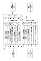
図1は、本技術の一実施形態に係るディスク記録再生装置(ディスク装置)30の構成例を示す模式的な図である。 FIG. 1 is a schematic diagram illustrating a configuration example of a disk recording / reproducing apparatus (disk apparatus) 30 according to an embodiment of the present technology.
スピンドルモータ32は、サーボ制御部35からのスピンドルモータ駆動信号に基づいて、光ディスク31をCLV(Constant Linear Velocity)又はCAV(Constant Angular Velocity)で回転駆動する。
The
ピックアップ部33は、信号処理部36から供給される記録信号に基づきレーザ光の出力を制御して、光ディスク31に記録信号を記録する。ピックアップ部33はまた、光ディスク31にレーザ光を集光して照射するとともに、光ディスク31からの反射光を光電変換して電流信号を生成し、RF(Radio Frequency)アンプ34に供給する。なお、レーザ光の照射位置は、サーボ制御部35からピックアップ部33に供給されるサーボ信号により所定の位置に制御される。
The
RFアンプ34は、ピックアップ部33からの電流信号に基づいて、フォーカス誤差信号及びトラッキング誤差信号、並びに再生信号を生成し、トラッキング誤差信号及びフォーカス誤差信号をサーボ制御部35に供給し、再生信号を信号処理部36に供給する。
The
サーボ制御部35は、フォーカスサーボ動作やトラッキングサーボ動作の制御を行う。具体的には、サーボ制御部35は、RFアンプ34からのフォーカス誤差信号とトラッキング誤差信号に基づいてフォーカスサーボ信号とトラッキングサーボ信号をそれぞれ生成し、ピックアップ部33のアクチュエータ(図示せず)に供給する。またサーボ制御部35は、スピンドルモータ32を駆動するスピンドルモータ駆動信号を生成して、光ディスク31を所定の回転速度で回転させるスピンドルサーボ動作の制御を行う。
The
さらにサーボ制御部35は、ピックアップ部33を光ディスク31の径方向に移動させてレーザ光の照射位置を変えるスレッド制御を行う。なお、光ディスク31の信号読み出し位置の設定は、制御部40によって行われ、設定された読み出し位置から信号を読み出すことができるようにピックアップ部33の位置が制御される。
Further, the
信号処理部36は、メモリコントローラ37から入力される記録データを変調して記録信号を生成し、ピックアップ部33に供給する。信号処理部36はまた、RFアンプ34からの再生信号を復調して再生データを生成し、メモリコントローラ37に供給する。
The
メモリコントローラ37は、データ変換部39からの記録データを、後述するように、適宜、メモリ38に記憶するとともに、それを読み出し、信号処理部36に供給する。メモリコントローラ37はまた、信号処理部36からの再生データを、適宜、メモリ38に記憶するとともに、それを読み出し、データ変換部39に供給する。
As will be described later, the
データ変換部39は、信号入出力装置51から供給される、例えば図示しないビデオカメラ等で撮影された撮影画像と音声の信号や、図示しない記録媒体から再生された信号を、必要に応じて、例えば、MPEG(Moving Picture Experts Group)、JPEG(Joint Photographic Experts Group)等の方式に基づいて圧縮して記録データを生成し、メモリコントローラ37に供給する。
The
データ変換部39はまた、メモリコントローラ37から供給される再生データを、必要に応じて伸張し、所定のフォーマットの出力信号に変換して、信号入出力装置51に供給する。
The
制御部40は、操作部41からの操作信号などに基づき、サーボ制御部35、信号処理部36、メモリコントローラ37、及びデータ変換部39を制御し、記録再生処理を実行させる。
The
操作部41は、例えば、ユーザによって操作され、その操作に対応する操作信号を、制御部40に供給する。
For example, the operation unit 41 is operated by a user and supplies an operation signal corresponding to the operation to the
以上のように構成されるディスク記録再生装置30では、ユーザが操作部41を操作することにより、データの記録を指令すると、信号入出力装置51から供給されるデータが、データ変換部39、メモリコントローラ37、信号処理部36、及びピックアップ部33を介して、光ディスク31に供給されて記録される。
In the disc recording / reproducing
また、ユーザが操作部41を操作することにより、データの再生を指令すると、光ディスク31から、ピックアップ部33、RFアンプ34、信号処理部36、メモリコントローラ37、及びデータ変換部39を介して、データが読み出されて再生され、信号入出力装置51に供給される。
In addition, when the user instructs to reproduce data by operating the operation unit 41, the
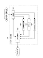
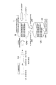
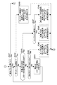
図2は、図1のデータ変換部39の構成例を示す模式的な図である。本実施形態では、このデータ変換部39が、複数のフレームを有する画像データを取り込む取り込み部として機能する。
FIG. 2 is a schematic diagram illustrating a configuration example of the
光ディスク31へのデータの記録時には、信号入出力装置51から記録すべき信号が、デマルチプレクサ61に供給される。デマルチプレクサ61は、信号入出力装置51から供給される信号から、関連する複数のデータ系列として、例えば、動画の(例えばベースバンドの)画像信号、その画像信号に付随する(例えばベースバンドの)音声信号及びメタデータをそれぞれ分離し、データ量検出部62に供給する。
When data is recorded on the
即ち、光ディスク31へのデータの記録時においては、信号入出力装置51は、上述したように、例えば、図示せぬビデオカメラで得られた信号を出力するが、このビデオカメラで得られる信号には、被写体の撮像を行うことにより得られる画像信号とその画像信号に付随する音声信号の他、その画像信号についてのメタデータも含まれており、デマルチプレクサ61は、そのような信号から、画像信号及び音声信号の他、メタデータも分離する。
That is, when recording data on the
ここで、メタデータとしては、その読み込み処理においてリアルタイム性が要求される内容のデータよりなるリアルタイムメタデータ(RT:Real Time metadata)と、その読み込み処理においてリアルタイム性が要求されない内容のデータよりなるノンリアルタイムメタデータ(NRT:Non Real Time metadata)が存在する。 Here, as the metadata, real-time metadata (RT: Real Time metadata) composed of data that requires real-time property in the reading process and non-content composed of data that does not require real-time property in the reading process. There is real-time metadata (NRT).
リアルタイムメタデータ(RT)としては、例えば、画像信号のフレームの位置を日時(年、月、日、時、分、秒、)等の所定の時間情報を利用して特定する、各フレームの絶対的な位置情報(タイムコード)であるLTC(Linear Time Code)、各フレームのフレーム番号であり、ファイルの先頭フレームからの相対的な位置情報であるFTC(File Time Code)がある。本実施形態では、LTC及びFTCが第1の位置情報及び第2の位置情報として用いられる。 As the real-time metadata (RT), for example, the frame position of the image signal is specified using predetermined time information such as date and time (year, month, day, hour, minute, second). There are LTC (Linear Time Code) which is typical position information (time code), the frame number of each frame, and FTC (File Time Code) which is relative position information from the first frame of the file. In the present embodiment, LTC and FTC are used as the first position information and the second position information.
その他リアルタイムメタデータとしては、フレームの画像信号の信号特性を示すユーザビット(UB:User Bit)、フレームを識別するためのIDであるUMID(Unique Material Identifier)、ビデオカメラによる撮像が行われた位置を表すGPS(Global Positioning System)の情報、画像信号や音声信号等のエッセンスデータの内容に関する情報であるエッセンスマーク、ARIB(Association of Radio Industries and Businesses)メタデータ、撮像が行われたビデオカメラの設定/制御情報等がある。なお、ARIBメタデータとは、標準化団体であるARIBで標準化された、SDI(Serial Digital Interface)等の通信インタフェース用のメタデータである。また、ビデオカメラの設定/制御情報とは、例えば、IRIS(アイリス)制御値や、ホワイトバランス/ブラックバランスのモード、レンズのズームやフォーカスに関するレンズ情報等の情報である。 Other real-time metadata includes a user bit (UB) indicating the signal characteristics of the image signal of the frame, a UMID (Unique Material Identifier) that is an ID for identifying the frame, and a position where the image is captured by the video camera. GPS (Global Positioning System) information, essence marks that are information about the contents of essence data such as image signals and audio signals, ARIB (Association of Radio Industries and Businesses) metadata, and settings of the video camera where the image was taken / Control information etc. The ARIB metadata is metadata for a communication interface such as SDI (Serial Digital Interface) standardized by ARIB, which is a standardization organization. The video camera setting / control information is, for example, information such as an IRIS (iris) control value, a white balance / black balance mode, and lens information related to lens zoom and focus.
ノンリアルタイムメタデータ(NRT)としては、例えば、各フレームに対応するLTCをフレーム番号(FTC)に対応させた変換テーブル、UMID、GPSの情報、又はその他の情報等ががある。本実施形態では、後述するLTC変化テーブルもノンリアルタイムメタデータとして記憶され、指定された再生フレームの再生処理を操作性よく実行するために用いられる。LTC変化テーブルは、本実施形態に係るテーブル情報に相当する。 Non-real-time metadata (NRT) includes, for example, a conversion table in which LTC corresponding to each frame is associated with a frame number (FTC), UMID, GPS information, or other information. In the present embodiment, an LTC change table, which will be described later, is also stored as non-real time metadata, and is used to execute the reproduction process of the designated reproduction frame with good operability. The LTC change table corresponds to the table information according to the present embodiment.
なお、フレームとは、画像信号の単位であり、1画面分の画像に対応する画像データ(又は、その画像データに対応する各種のデータ)のことである。また、クリップとは、撮影者が撮像を開始して終了するまでの1回の撮像処理を示す単位である。すなわち、1つのクリップの画像信号は、通常、複数のフレームの画像信号からなる。なお、クリップは、1回の撮像処理を示すだけでなく、その撮像処理の撮像開始から撮像終了までの時間を示す場合にも用いられる。また、クリップは、その1回の撮像処理により得られる画像データの長さやデータ量を示したり、その画像データ自体を示したりする場合にも用いられるし、その1回の撮像処理により得られる各種のデータの長さやデータ量を示したり、その各種のデータの集合体そのものを示したりする場合にも用いられる。 A frame is a unit of an image signal, and is image data corresponding to an image for one screen (or various data corresponding to the image data). A clip is a unit indicating one imaging process until the photographer starts imaging and ends imaging. That is, the image signal of one clip is usually composed of image signals of a plurality of frames. Note that the clip is used not only to indicate one imaging process but also to indicate the time from the imaging start to the imaging end of the imaging process. The clip is also used to indicate the length and amount of image data obtained by one imaging process, or to indicate the image data itself, and various clips obtained by the one imaging process. It is also used to indicate the length and amount of data, and to indicate a collection of various data.
なお、リアルタイムメタデータ及びノンリアルタイムメタデータは、どのような単位の画像データに対して付加されてもよい。以下においては、リアルタイムメタデータがフレーム毎に画像データに付加され、ノンリアルタイムメタデータがクリップ毎に画像データに付加される場合について説明する。すなわち、以下においては、リアルタイムメタデータは、画像信号に対して、フレーム毎に付加されるフレームメタデータであり、付加されたフレームに対応するデータを含んでいるものとする。また、ノンリアルタイムメタデータは、画像信号に対して、クリップ毎に付加されるクリップメタデータであり、付加されたクリップ全体に対応するデータを含んでいるものとする。 Real-time metadata and non-real-time metadata may be added to any unit of image data. In the following, a case where real-time metadata is added to image data for each frame and non-real-time metadata is added to image data for each clip will be described. That is, in the following, it is assumed that the real-time metadata is frame metadata added to the image signal for each frame and includes data corresponding to the added frame. Further, the non-real-time metadata is clip metadata added for each clip to the image signal, and includes data corresponding to the entire added clip.
通常、画像データは、クリップ毎にファイル化され、ファイルシステムにより管理される。このような場合、ノンリアルタイムメタデータは、画像データを含むファイル毎のメタデータであることとすることもできる。 Normally, image data is filed for each clip and managed by a file system. In such a case, the non-real-time metadata may be metadata for each file including image data.
なお、リアルタイムメタデータとノンリアルタイムメタデータは、上述した以外のデータを含むようにしてもよい。また、リアルタイムメタデータとノンリアルタイムメタデータで同じ内容のデータを含めるようにしてもよいし、上述したリアルタイムメタデータとしての各データをノンリアルタイムメタデータとしてもよいし、逆に、ノンリアルタイムメタデータとして上述した各データをリアルタイムメタデータとしてもよい。例えば、エッセンスマーク、ARIBメタデータ、又は、ビデオカメラの設定/制御情報等をノンリアルタイムメタデータとしてもよいし、リアルタイムメタデータ及びノンリアルタイムメタデータの両方に含めるようにしてもよい。また、UMIDやGPSの情報等をリアルタイムメタデータに含めるようにしてもよいし、リアルタイムメタデータ及びノンリアルタイムメタデータの両方に含めるようにしてもよい。 Note that the real-time metadata and the non-real-time metadata may include data other than those described above. In addition, the same content data may be included in the real-time metadata and the non-real-time metadata, or each data as the above-described real-time metadata may be the non-real-time metadata. Each data described above may be real-time metadata. For example, essence marks, ARIB metadata, video camera setting / control information, and the like may be included as non-real-time metadata, or may be included in both real-time metadata and non-real-time metadata. Further, UMID and GPS information may be included in the real-time metadata, or may be included in both real-time metadata and non-real-time metadata.
データ量検出部62は、デマルチプレクサ61から供給される画像信号、音声信号、リアルタイムメタデータ、又はノンリアルタイムメタデータを、そのまま、画像信号変換部63、音声信号変換部64、リアルタイムメタデータ処理部66、ノンリアルタイムメタデータ処理部67にそれぞれ供給するとともに、その画像信号、音声信号、リアルタイムメタデータ、又はノンリアルタイムメタデータのそれぞれのデータ量を検出し、メモリコントローラ37に供給する。即ち、データ量検出部62は、デマルチプレクサ61から供給される画像信号、音声信号、リアルタイムメタデータ、又はノンリアルタイムメタデータのそれぞれについて、例えば、所定の再生時間分のデータ量を検出し、メモリコントローラ37に供給する。
The data amount
また、データ量検出部62は、デマルチプレクサ61から供給される画像信号、さらには、必要に応じて音声信号を、ローレゾデータ生成部65に供給する。
In addition, the data
画像信号変換部63は、データ量検出部62から供給される画像信号を、例えば、すべてのフレームをI(Intra)ピクチャとしてMPEGエンコードし、その結果得られる画像データのデータ系列を、メモリコントローラ37に供給する。また、音声信号変換部64は、データ量検出部62から供給される音声信号を、例えばMPEGエンコードし、その結果得られる音声データのデータ系列を、メモリコントローラ37に供給する。
The image
リアルタイムメタデータ処理部66は、データ量検出部62を介して供給されるリアルタイムメタデータの各構成要素を、必要に応じて配置し直し、その結果得られるリアルタイムメタデータのデータ系列を、メモリコントローラ37に供給する。また、リアルタイムメタデータ処理部66は、信号入出力装置51より供給される信号にLTCデータが付加されていない場合等に、各フレームに対応するLTCデータを生成するLTCデータ処理部71を有している。さらに、リアルタイムメタデータ処理部66は、処理後のLTCデータのデータ系列をノンリアルタイムメタデータ処理部67にも、必要に応じて供給する。
The real-time
ノンリアルタイムメタデータ処理部67は、データ量検出部62を介して供給されるノンリアルタイムメタデータの各構成要素を、必要に応じて配置し直し、その結果得られるノンリアルタイムメタデータのデータ系列を、メモリコントローラ37に供給する。また、ノンリアルタイムメタデータ処理部67は、LTCデータ処理部72を有している。LTCデータ処理部72は、リアルタイムメタデータ処理部66より供給されるLTCデータのデータ系列を用いて、LTCデータとフレーム番号(FTCデータ)を関連付ける変換テーブルを生成する。本実施形態では、LTCデータ処理部72により、LTC変化テーブルが作成され、メモリコントローラ37を介してメモリ38に書き込まれる。すなわち本実施形態では、LTCデータ処理部72が書き込み部として機能し、メモリ38がテーブル記憶部として機能する。
The non-real-time
ローレゾデータ生成部65は、そこに供給されるデータのデータ量を少なくしたデータであるローレゾデータのデータ系列を生成し、メモリコントローラ37に供給する。
The low resolution
即ち、ローレゾデータ生成部65は、データ量検出部62を介して供給される画像信号の各フレームの画素数を間引く等することによって、画素数の少ないフレームの画像信号である少画像信号を生成する。さらに、ローレゾデータ生成部65は、その少画像信号を、例えば、MPEG4方式でエンコードし、そのエンコード結果を、ローレゾデータとして出力する。
That is, the low resolution
なお、ローレゾデータ生成部65では、データ量検出部62を介して供給される音声信号、あるいは、その音声信号のサンプルを間引く等することによってデータ量を少なくした音声信号を、ローレゾデータに含めて(例えば、フレーム単位等で、少画像信号に多重化した形で)出力するようにすることが可能である。本実施形態では、ローレゾデータには、音声信号が含まれる。
The low resolution
ここで、画像信号変換部63が出力する画像データのデータ系列及び音声信号変換部64が出力する音声データと、ローレゾデータ生成部65が出力するローレゾデータのデータ系列とは、同一内容の画像及び音声のデータ系列であるが、画像信号変換部63が出力する画像データ及び音声信号変換部64が出力する音声データは、いわば本来的に、ユーザに提供されるべきものであり、このことから、画像信号変換部63が出力する画像データ及び音声信号変換部64が出力する音声データを、以下、適宜、本線データという。
Here, the data sequence of the image data output from the image
ローレゾデータは、上述したように、本線データと同一内容の画像及び音声のデータではあるが、そのデータ量が少ない。従って、ある再生時間の再生を行うとした場合、ローレゾデータは、本線データに比較して、光ディスク31から短時間で読み出すことができる。
As described above, the low resolution data is image and audio data having the same contents as the main line data, but the data amount is small. Accordingly, when reproduction is performed for a certain reproduction time, the low resolution data can be read from the
なお、本線データのデータレートとしては、例えば、25Mbps(Mega bit per second)程度を採用することができる。この場合、ローレゾデータのデータレートとしては、例えば、3Mbps程度を採用することができる。さらに、この場合、メタデータ(リアルタイムメタデータ及びノンリアルタイムメタデータ)のデータレートとして、例えば、2Mbps程度を採用することとすると、光ディスク31に記録するデータ全体のデータレートは、30(=25+3+2)Mbps程度となる。従って、光ディスク31(をドライブするディスク記録再生装置30)としては、例えば、35Mbpsなどの記録レートを有する、十分実用範囲内のものを採用することが可能である。
In addition, as a data rate of main line data, about 25 Mbps (Mega bit per second) is employable, for example. In this case, as the data rate of the low resolution data, for example, about 3 Mbps can be employed. Further, in this case, if the data rate of metadata (real-time metadata and non-real-time metadata) is, for example, about 2 Mbps, the data rate of the entire data recorded on the
以上のように、図2のデータ変換部39では、本線データ(画像データ及び音声データ)のデータ系列の他、リアルタイムメタデータ、ノンリアルタイムメタデータ、及びローレゾデータのデータ系列も、メモリコントローラ37に供給される。そして、メモリコントローラ37に供給された本線データ、リアルタイムメタデータ、ノンリアルタイムメタデータ、及びローレゾデータは、光ディスク31に供給されて記録される。
As described above, in the
一方、光ディスク31からのデータの再生時においては、光ディスク31から、必要に応じて、本線データ、リアルタイムメタデータ、ノンリアルタイムメタデータ、又はローレゾデータが読み出される。そして、本線データを構成する画像データと音声データは、画像データ変換部81と音声データ変換部82にそれぞれ供給され、画像信号と音声信号にデコードされて、マルチプレクサ86に供給される。
On the other hand, when reproducing data from the
また、リアルタイムメタデータ、ノンリアルタイムメタデータ、並びに、ローレゾデータは、それぞれ、リアルタイムメタデータ処理部84、ノンリアルタイムメタデータ処理部85、並びに、ローレゾデータ処理部83に供給される。リアルタイムメタデータ処理部84は、そこに供給されるリアルタイムメタデータの各構成要素の配置位置を必要に応じて変更し、マルチプレクサ86に供給する。ノンリアルタイムメタデータ処理部85は、そこに供給されるノンリアルタイムメタデータの各構成要素の配置位置を必要に応じて変更し、マルチプレクサ86に供給する。ローレゾデータ処理部83は、そこに供給されるローレゾデータをデータ量の少ない画像信号と音声信号にデコードし、マルチプレクサ86に供給する。
The real-time metadata, the non-real-time metadata, and the low-resolution data are supplied to the real-time
画像データ変換部81は、メモリコントローラ37から供給される画像データのデータ系列を、例えばMPEGデコードし、その結果得られる画像信号を、マルチプレクサ86に供給する。また、音声データ変換部82は、メモリコントローラ37から供給される音声データのデータ系列を、例えばMPEGデコードし、その結果得られる音声信号を、マルチプレクサ86に供給する。
The image
マルチプレクサ86は、画像データ変換部81から供給される画像信号、音声データ変換部82から供給される音声信号、リアルタイムメタデータ処理部84から供給されるリアルタイムメタデータ、及びノンリアルタイムメタデータ処理部85から供給されるノンリアルタイムメタデータを、信号入出力装置51に供給する。なお、マルチプレクサ86では、画像データ変換部81から供給される画像信号、音声データ変換部82から供給される音声信号、リアルタイムメタデータ処理部84から供給されるリアルタイムメタデータ、ノンリアルタイムメタデータ処理部85から供給されるノンリアルタイムメタデータ、ローレゾデータ処理部83から供給されるデータ量の少ない画像信号及び音声信号を多重化して出力するようにすることも、それぞれの信号(データ)を、独立に、並列して出力するようにすることも可能である。
The
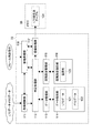
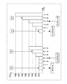
図3は、図2のリアルタイムメタデータ処理部66が有するLTCデータ処理部71の構成例を示す模式的な図である。
FIG. 3 is a schematic diagram illustrating a configuration example of the LTC
図3に示すLTCデータ処理部71を内蔵する、図2のリアルタイムメタデータ処理部66は、供給されるリアルタイムメタデータにLTCが存在しない等の場合、LTCデータ処理部71に制御信号や同期信号を供給し、LTCの生成を要求する。リアルタイムメタデータにLTCが存在しない場合としては、例えば、信号入出力装置51に接続された撮像装置により得られた画像信号や音声信号が供給された場合等がある。
The real-time
LTCデータ処理部71の制御部101は、その制御信号及び同期信号を取得すると、それらの信号に基づいて、LTCデータ処理部71の各部を制御し、LTCの生成処理を行う。
When the
所定の時刻を基準とする、実際の時刻とは独立したLTCを生成する場合、制御部101は、LTCの生成処理を行うLTC生成部102、初期値の設定処理を行う初期値設定部103、及びフレームをカウントするカウンタ104を制御し、各種の処理を実行する。
When generating an LTC independent of the actual time with reference to a predetermined time, the
初期値設定部103は、制御部101に制御され、初期値の設定に関する処理を実行する。そして、初期値設定部103は、設定した初期値をLTC生成部102に供給する。カウンタ104は、制御部101に供給された同期信号に基づいて、処理対象のフレーム数をカウントし、そのカウント値をLTC生成部102に供給する。また、リアルタイムクロック105は、実際の時刻に関する情報である時刻情報を保持しており、制御部101に制御されて、その時刻情報をLTC生成部102に供給する。
The initial
LTC生成部102は、制御部101に制御され、例えば、初期値設定部103に供給された初期値、及びカウンタ104により供給されたカウンタ値を用いて、フレームに同期したLTCデータを生成し、そのLTCデータをリアルタイムメタデータ処理部66に供給する。
The
また、実際の時刻を用いたLTCを生成する場合、制御部101は、LTCの生成処理を行うLTC生成部102、実際の時刻情報を供給するリアルタイムクロック105を制御し、各種の処理を実行する。この場合、LTC生成部102は、制御部101に制御され、リアルタイムクロック105に供給される時刻情報を用いて、フレームに同期したLTCデータを生成し、そのLTCデータをリアルタイムメタデータ処理部66に供給する。
Further, when generating an LTC using actual time, the
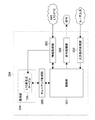
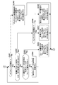
図4は、図2のノンリアルタイムメタデータ処理部67が有するLTCデータ処理部72の構成例を示す模式的な図である。
FIG. 4 is a schematic diagram illustrating a configuration example of the LTC
図4に示されるLTCデータ処理部72を内蔵する、図2のノンリアルタイムメタデータ処理部67は、例えば、リアルタイムメタデータ処理部66よりLTCデータが供給される場合、LTCデータ処理部72にそのLTCデータを供給し、LTCの値の増加や減少等の、その変化パターンが変わるフレーム(変化点)を検出させ、その変化点におけるLTCとFTCの対応関係を要素とするLTC変化点テーブルを作成させる。
The non-real-time
LTCデータ処理部72は、外部より供給されるLTCデータやFTCデータを取得する取得制御部111、各種の判定処理を行う判定処理部112、外部より供給されるLTCデータやFTCデータを管理するデータ管理部113、データ管理部113に制御されて、LTCデータ121やFTCデータ122を保持するデータ保持部114、後述するように判定処理部112より供給される、クリップ内における所定の区間に対する設定を管理する区間設定管理部115、区間設定管理部115に制御されて、設定された区間名123を保持する区間設定保持部116、判定処理部112より供給されたLTC変化点テーブルをメモリ38に供給し、LTC変化点テーブルを保持させる登録処理部117、並びに、キューアップ処理を排他的に制御する排他処理部118を内蔵している。
The LTC
取得制御部111は、所定の容量のキャッシュ(図示せず)を内蔵しており、リアルタイムメタデータ処理部66より供給されるLTCデータやFTCデータを内蔵するキャッシュに一旦保持し、所定のデータ量毎に判定処理部112に供給する。
The
判定処理部112は、各部より供給される各種のデータに基づいて、各種の判定処理を行い、その判定結果に基づいて、各種のデータを保持させたり、生成されたLTC変化点テーブルの要素を登録処理部117に供給したりする。
The
データ管理部113は、データ保持部114により保持されているLTCデータ121及びFTCデータ122の入出力を管理する。例えば、データ管理部113は、判定処理部112より供給されたLTCデータやFTCデータをデータ保持部114に供給して保持させたり、判定処理部112の要求に基づいて、データ保持部114に保持されているLTCデータ121やFTCデータ122を取得し、判定処理部112に供給したりする。
The
データ保持部114は、例えば、ハードディスク等の記憶媒体よりなり、データ管理部113の要求に基づいて、その記憶領域に保持されているLTCデータ121やFTCデータ122をデータ管理部113に供給したり、データ管理部113より供給されたLTCデータやFTCデータを保持したりする。
The
区間設定管理部115は、判定処理部112の要求に基づいて、区間設定保持部116に保持されている区間名123を取得して判定処理部112に供給したり、判定処理部112より供給された区間名を区間設定保持部116に供給して保持させたりする。区間設定保持部116は、例えば、ハードディスク等の記憶媒体よりなり、区間設定管理部115の要求に基づいて、その記憶領域に保持されている区間名123を区間設定管理部115に供給したり、区間設定管理部115より供給された区間名を保持したりする。
The section
なお、この区間とは、LTCの変化点によってクリップを分割したときの、隣り合うLTCの変化点に挟まれる区間のことである。上述したように、LTCの変化点とは、LTCの値の増加や減少の変化パターン(LTC変化パターン)が変わるフレームのことであり、後述するように予め定められた複数のLTC変化パターンによって分類された各フレームの内、そのLTC変化パターンが次のフレームのLTC変化パターンと異なるフレームのことである。すなわち、1つの区間に含まれるフレームのLTC変化パターンは全て同じである。つまり、この区間は、クリップに含まれる全フレームをLTCの変化パターンによって分割し、LTC変化パターンが互いに同じである連続するフレームをまとめたものである。 This section is a section sandwiched between adjacent LTC change points when a clip is divided by LTC change points. As described above, the LTC change point is a frame in which the LTC change pattern (LTC change pattern) changes, and is classified by a plurality of predetermined LTC change patterns as described later. Of each frame, the LTC change pattern is a frame different from the LTC change pattern of the next frame. That is, the LTC change patterns of the frames included in one section are all the same. That is, this section is obtained by dividing all the frames included in the clip by the LTC change pattern and collecting consecutive frames having the same LTC change pattern.
通常、クリップの画像データは、複数のフレームによって構成され、複数のLTCの変化点を有している。区間は、隣り合うLTCの変化点に挟まれる区間のことであるので、従って、クリップは1つ以上の区間に分割することができる。 Usually, the image data of a clip is composed of a plurality of frames and has a plurality of LTC change points. Since the section is a section sandwiched between adjacent LTC change points, the clip can be divided into one or more sections.
なお、LTCの変化パターンは、後述するように、区間のステータスとして、対応する変化点のLTCやFTCに対応付けられ、LTC変化テーブルに登録される。このLTC変化パターンとしては、次のフレームにおけるLTCの値が現在のフレームにおけるLTCの値より1つ大きいことを示す「インクリメント」、次のフレームにおけるLTCの値が現在のフレームにおけるLTCの値より2つ以上大きいことを示す「インクリース」、次のフレームにおけるLTCの値が現在のフレームにおけるLTCの値と同じであることを示す「スティル」、次のフレームにおけるLTCの値が現在のフレームにおけるLTCの値より1つ以上小さいことを示す「ディクリース」、次のフレームが存在しない(現在のフレームが、クリップの最終フレームである)ことを示す「エンド」、作成されたLTC変化点テーブルの要素を蓄積していき、LTC変化点テーブルを作成するメモリ38の空き容量が不足したことを示す「オーバ」等がある。
As will be described later, the LTC change pattern is associated with the LTC or FTC of the corresponding change point as a section status and registered in the LTC change table. The LTC change pattern includes “increment” indicating that the LTC value in the next frame is one greater than the LTC value in the current frame, and the LTC value in the next frame is 2 more than the LTC value in the current frame. “Increase” indicating that the value is greater than or equal to “Still” indicating that the LTC value in the next frame is the same as the LTC value in the current frame, and the LTC value in the next frame is the LTC in the current frame. "Decrease" indicating one or more less than the value of "," "End" indicating that the next frame does not exist (the current frame is the last frame of the clip), elements of the created LTC change point table , And the free space of the
区間設定保持部116は、このようなLTC変化点テーブル、すなわち、区間のステータスの名前を区間名123として保持する。
The section setting holding unit 116 holds such an LTC change point table, that is, a section status name as the
登録処理部117は、判定処理部112より供給されたLTC変化点テーブルの要素を、メモリコントローラ37を介してメモリ38に供給する。
The
排他処理部118は、後述するキューアップ処理部から送られてくるフレームの再生指示に基づいたキューアップ処理を排他的に制御する。すなわち排他処理部118は、フレームの再生指示の発生時に、LTC変化点テーブルの作成処理及びメモリ38への書き込み処理を規制しつつ、それまでに書き込みが完了しているLTC変化点テーブルの参照を可能とする。
The
本実施形態では、フレームの再生指示を受けた排他処理部118により、取得制御部111の情報取得処理が規制される。また排他処理部118により、LTC変化点テーブルの書き込み完了情報が生成され、当該情報が登録処理部117を介して出力しメモリ38に書き込まれる。しかしながら、LTC変化点テーブルの書き込み処理の規制の方法は限定されない。例えば排他処理部118により、判定処理部112の判定処理が規制されてもよい。
In the present embodiment, the information acquisition process of the
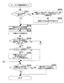
図5は、本実施形態に係る制御部40が行うコンテンツデータの記録処理の一例を示すフローチャートである。
FIG. 5 is a flowchart illustrating an example of content data recording processing performed by the
操作部41が操作されることによって、記録処理開始を指令する旨の操作信号が、操作部41から制御部40に供給されると、制御部40は、記録処理を開始する。
When the operation unit 41 is operated and an operation signal for instructing the start of the recording process is supplied from the operation unit 41 to the
即ち、制御部40は、最初に、ステップS1において、音声年輪サイズTsa及び画像年輪サイズTsv、さらには、ローレゾ年輪サイズTslとリアルタイムメタ年輪サイズTsmとを設定する。
That is, first, in step S1, the
ここで、音声年輪サイズTsaは、光ディスク31にひとまとめで配置して記録する音声データのデータ量を決定する変数で、例えば、音声信号の再生時間によって表される。画像年輪サイズTsvも、同様に、光ディスク31にひとまとめで配置して記録する画像データのデータ量を決定する変数で、例えば、画像信号の再生時間によって表される。
Here, the audio annual ring size Tsa is a variable that determines the amount of audio data that is collectively arranged and recorded on the
また、ローレゾ年輪サイズTslは、光ディスク31にひとまとめで配置して記録するローレゾデータのデータ量を決定する変数で、例えば、上述の音声年輪サイズTsa及び画像年輪サイズTsvと同様に、そのローレゾデータの元となった画像信号(又は音声信号)の再生時間によって表される。リアルタイムメタ年輪サイズTsmも、同様に、光ディスク31にひとまとめで配置して記録するリアルタイムメタデータのデータ量を決定する変数で、例えば、上述の音声年輪サイズTsa及び画像年輪サイズTsvと同様に、そのリアルタイムメタデータによって各種の情報(例えば、画像の撮像が行われた日時など)が説明される画像信号(又は音声信号)の再生時間によって表される。
The low-resolution annual ring size Tsl is a variable that determines the amount of low-resolution data to be arranged and recorded on the
なお、音声年輪サイズTsa、画像年輪サイズTsv、ローレゾ年輪サイズTsl、及びリアルタイムメタ年輪サイズTsmを、例えば、ビット数やバイト数などのデータ量そのものによって表すのではなく、再生時間によって、いわば間接的に表すようにしたのは、次のような理由による。 Note that the audio annulus size Tsa, the image annulus size Tsv, the low-resolution annulus size Tsl, and the real-time meta annulus size Tsm are not represented by, for example, the data amount itself such as the number of bits and the number of bytes, but indirectly by the playback time. The reason for this is as follows.
即ち、図5の記録処理によれば、光ディスク31には、音声データの系列から抽出された音声年輪サイズTsaに基づくデータ量ごとの音声データのまとまりである音声年輪データ、及び画像データの系列から抽出された画像年輪サイズTsvに基づくデータ量ごとの画像データのまとまりである画像年輪データが光ディスク31に周期的に配置されて記録される。また、ローレゾデータのデータ系列から抽出されたローレゾ年輪サイズTslに基づくデータ量ごとのローレゾデータのまとまりであるローレゾ年輪データ、及びリアルタイムメタデータのデータ系列から抽出されたリアルタイムメタ年輪サイズTsmに基づくデータ量ごとのリアルタイムメタデータのまとまりであるリアルタイムメタ年輪データも記録される。
That is, according to the recording process of FIG. 5, the
このように、光ディスク31に、音声年輪データ、画像年輪データ、ローレゾ年輪データ、及びリアルタイムメタ年輪データが周期的に配置されて記録される場合、画像と音声の再生を考えると、その再生は、画像信号とその画像信号に付随する音声信号とが揃わないと行うことができない。かかる再生の観点からは、ある再生時間帯の音声年輪データと、その再生時間帯の画像年輪データとは、光ディスク31上の近い位置、即ち、例えば、隣接する位置に記録すべきである。
As described above, when audio annual ring data, image annual ring data, low-resolution annual ring data, and real-time meta annual ring data are periodically recorded and recorded on the
また、ローレゾ年輪データは、音声年輪データや画像年輪データのデータ量を少なくしたものであるから、ある再生時間帯の音声年輪データ及び画像年輪データと、その再生時間帯の音声年輪データや画像年輪データのデータ量を少なくしたローレゾ年輪データとは、光ディスク31上の近い位置に記録すべきである。さらに、リアルタイムメタ年輪データは、音声年輪データや画像年輪データに関する情報を表すものであるから、やはり、ある再生時間帯の音声年輪データ及び画像年輪データと、その再生時間帯の音声年輪データや画像年輪データに関する情報を表すリアルタイムメタ年輪データとは、光ディスク31上の近い位置に記録すべきである。
In addition, since the low-resolution annulus data is obtained by reducing the data volume of the audio annulus data and the image annulus data, the audio annulus data and the image annulus data in a certain playback time zone, and the audio annulus data and the image annulus data in the playback time zone. Low-resolution annual ring data with a reduced data amount should be recorded at a close position on the
しかしながら、同一の再生時間分の音声データと画像データのデータ量を比較した場合、それらのデータ量は、一般に大きく異なる。即ち、ある再生時間分の音声データのデータ量は、その再生時間分の画像データのデータ量に比較してかなり少ない。さらに、音声データや画像データのデータレートが、固定ではなく、可変となっているケースもある。同様に、同一の再生時間分の音声データや画像データのデータレートと、ローレゾデータやリアルタイムメタデータのデータレートとを比較した場合、音声データや画像データのデータレートに比較して、ローレゾデータやリアルタイムメタデータのデータレートは小である。 However, when comparing the amount of audio data and image data for the same playback time, the amount of data generally differs greatly. That is, the amount of audio data for a certain reproduction time is considerably smaller than the amount of image data for the reproduction time. Furthermore, there are cases where the data rate of audio data or image data is not fixed but variable. Similarly, when the data rate of audio data or image data for the same playback time is compared with the data rate of low resolution data or real-time metadata, the data rate of low resolution data or The data rate of real-time metadata is small.
従って、音声年輪サイズTsaと画像年輪サイズTsvとをデータ量で表し、そのデータ量ごとの音声年輪データと画像年輪データを、音声データと画像データの系列それぞれから順次抽出すると、各再生時間帯の画像年輪データに対して、再生時刻が徐々に進んだ(先の)再生時間帯の音声年輪データが得られるようになり、その結果、同一の再生時間帯に再生されるべき音声データと画像データとを、光ディスク31上の近い位置に配置することが困難となる。
Therefore, when the audio annulus size Tsa and the image annulus size Tsv are represented by the data amount, and the audio annulus data and the image annulus data for each data amount are sequentially extracted from the respective sequences of the audio data and the image data, With respect to the image annulus data, audio annulus data in the playback time zone in which the playback time gradually advanced (previous) can be obtained. As a result, the audio data and the image data to be played back in the same playback time zone It is difficult to dispose these at close positions on the
同様に、ローレゾ年輪サイズTslとリアルタイムメタ年輪サイズTsmを、データ量で表すと、上述した音声年輪サイズTsa及び画像年輪サイズTsvをデータ量で表した場合と同様に、同じような再生時間帯に再生されるべき音声データ、画像データ、ローレゾデータ、及びリアルタイムメタデータを、光ディスク31上の近い位置に配置することが困難となる不都合が生じる。
Similarly, when the low-resolution annulus size Tsl and the real-time meta annulus size Tsm are represented by the data amount, similarly to the above-described case where the audio annulus size Tsa and the image annulus size Tsv are represented by the data amount, There arises a disadvantage that it is difficult to arrange audio data, image data, low resolution data, and real-time metadata to be reproduced at close positions on the
そこで、音声年輪サイズTsa、画像年輪サイズTsv、ローレゾ年輪サイズTsl、及びメタ年輪サイズTsmを再生時間で表し、これにより、同じような再生時間帯に再生されるべき音声データ、画像データ、ローレゾデータ、及びリアルタイムメタデータを、光ディスク31上の近い位置に配置することができるようにしている。
Therefore, the audio annulus size Tsa, the image annulus size Tsv, the low resolution annulus size Tsl, and the meta annulus size Tsm are represented by the reproduction time, and thereby, the audio data, image data, and low resolution data to be reproduced in the same reproduction time zone. , And real-time metadata can be arranged at a close position on the
なお、ステップS1で設定される音声年輪サイズTsa、画像年輪サイズTsv、ローレゾ年輪サイズTsl、及びリアルタイムメタ年輪サイズTsmの値は、あらかじめ定められた固定の値でも良いし、可変の値でも良い。音声年輪サイズTsaや、画像年輪サイズTsv、ローレゾ年輪サイズTsl、メタ年輪サイズTsmの値を可変とする場合には、その可変の値は、例えば、操作部41を操作することによって入力されるようにすることができる。 Note that the values of the sound annual ring size Tsa, the image annual ring size Tsv, the low-resolution annual ring size Tsl, and the real-time meta annual ring size Tsm set in step S1 may be fixed values that are set in advance or may be variable values. When the values of the sound annual ring size Tsa, the image annual ring size Tsv, the low resolution annual ring size Tsl, and the meta annual ring size Tsm are variable, the variable values are input by operating the operation unit 41, for example. Can be.
ステップS1の処理後は、ステップS2に処理を進め、制御部40は、データ変換部39を制御して、信号入出力装置51からディスク記録再生装置30に供給される音声信号と画像信号を圧縮符号化して、音声データの系列と画像データの系列とする音声信号変換処理と画像信号変換処理をそれぞれ開始させるとともに、メモリコントローラ37を制御して、データ変換部39で得られた音声データと画像データをメモリ18に供給して記憶させる音声データ記憶処理と画像データ記憶処理をそれぞれ開始させる。
After the process of step S1, the process proceeds to step S2, and the
さらに、ステップS2では、制御部40は、データ変換部39を制御して、信号入出力装置51からディスク記録再生装置30に供給されるリアルタイムメタデータの系列を処理するリアルタイムメタデータ処理と、信号入出力装置51からディスク記録再生装置30に供給される音声信号と画像信号からローレゾデータの系列を生成するローレゾデータ生成処理とを開始させるとともに、メモリコントローラ37を制御して、データ変換部39で得られたリアルタイムメタデータとローレゾデータをメモリ38に供給して記憶させるリアルタイムメタデータ記憶処理とローレゾデータ記憶処理をそれぞれ開始させる。
Further, in step S2, the
また、ステップS2において、制御部40は、データ変換部39を制御して、信号入出力装置51からディスク記録再生装置30に供給されるノンリアルタイムメタデータの系列の処理等を実行したり、得られたリアルタイムメタデータに含まれるLTCを用いて、LTCに関する処理を実行したりするノンリアルタイムメタデータ処理を開始させるとともに、メモリコントローラ37を制御して、データ変換部39で得られたノンリアルタイムメタデータに供給して記憶させるノンリアルタイムメタデータ記憶処理を開始させる。
In
そして、制御部40は、ステップS3において、音声データを光ディスク31に記録させる制御タスクである音声データ記録タスクを開始するとともに、ステップS4において、画像データを光ディスク31に記録させる制御タスクである画像データ記録タスクを開始し、ステップS5に処理を進める。ステップS5では、制御部40は、ローレゾデータを光ディスク31に記録させる制御タスクであるローレゾデータ記録タスクを開始し、ステップS6では、リアルタイムメタデータを光ディスク31に記録させる制御タスクであるリアルタイムメタデータ記録タスクを開始し、ステップS7に処理を進める。
In step S3, the
なお、ステップS3における音声データ記録タスク、ステップS4における画像データ記録タスク、ステップS5におけるローレゾデータ記録タスク、及びステップS6におけるリアルタイムメタデータ記録タスクについては、各データを記録するためのどのようなアルゴリズムが用いられてもよく、特に限定されない。 For the audio data recording task in step S3, the image data recording task in step S4, the low-resolution data recording task in step S5, and the real-time metadata recording task in step S6, what algorithm is used for recording each data? It may be used and is not particularly limited.
ステップS7では、制御部40は、操作部41から、データの記録の終了を指令する操作信号が供給されたかどうかを判定し、供給されていないと判定した場合、ステップS8に進み、制御部40は、すべての記録タスクが終了したかどうかを判定する。ステップS8おいて、すべての記録タスクが終了していないと判定された場合、制御部40は、ステップS7に処理を戻し、それ以降の処理を繰り返す。
In step S7, the
一方、ステップS7において、データの記録の終了を指令する操作信号が供給されたと判定された場合、即ち、例えば、ユーザが、データの記録を終了するように、操作部41を操作した場合、ステップS9に進み、制御部40は、ステップS2で開始させた音声信号変換処理、画像信号変換処理、リアルタイムメタデータ処理、及びローレゾデータ生成処理、並びに音声データ記憶処理、画像データ記憶処理、リアルタイムメタデータ記憶処理、及びローレゾデータ記憶処理を終了させ、ステップS10に処理を進める。
On the other hand, if it is determined in step S7 that an operation signal for instructing the end of data recording has been supplied, that is, for example, if the user operates the operation unit 41 to end the data recording, In step S9, the
ステップS10において、制御部40は、ステップS8における場合と同様に、すべての記録タスクが終了したかどうかを判定し、終了したと判定するまで待機する。
In step S10, as in the case of step S8, the
また、ステップS10において、すべての記録タスクが終了したと判定された場合、即ち、ステップS3で開始された音声データ記録タスク、ステップS4で開始された画像データ記録タスク、ステップS5で開始されたローレゾデータ記録タスク、及びステップS6で開始されたリアルタイムメタデータ記録タスクのすべてが終了した場合、制御部40は、ステップS11に処理を進める。
If it is determined in step S10 that all the recording tasks have been completed, that is, the audio data recording task started in step S3, the image data recording task started in step S4, and the low resolution started in step S5. When all of the data recording task and the real-time metadata recording task started in step S6 are completed, the
また、ステップS8において、すべての記録タスクが終了したと判定された場合、即ち、ステップS3で開始された音声データ記録タスク、ステップS4で開始された画像データ記録タスク、ステップS5で開始されたローレゾデータ記録タスク、及びステップS6で開始されたリアルタイムメタデータ記録タスクのすべてが終了している場合、制御部40は、ステップS11に処理を進める。
If it is determined in step S8 that all recording tasks have been completed, that is, the audio data recording task started in step S3, the image data recording task started in step S4, and the low resolution started in step S5. If all of the data recording task and the real-time metadata recording task started in step S6 have been completed, the
ステップS11において、制御部40は、メモリコントローラ37を制御して、メモリ38に記憶されているノンリアルタイムメタデータを読み出し、セクタの整数倍のデータ量となるようにパディング(PADDING)して、信号処理部36に供給することにより、セクタの整数倍のノンリアルタイムメタデータが、その整数倍の数のセクタに記録されるように記録制御する。
In step S11, the
ここでいうセクタは、光ディスク31上に形成される物理的記録再生単位(物理的単位領域)となるものである。その他、、光ディスク31の物理的単位領域として、例えばECC(Error Correction Code:誤り訂正符号)処理が施される単位のデータが記録されるECCブロックが用いられてもよい。また、例えば複数の固定数のセクタや、複数の固定数のECCブロックが用いられてもよい。
The sector here is a physical recording / reproducing unit (physical unit area) formed on the
制御部40は、ステップS12に処理を進め、ノンリアルタイムメタデータ処理を終了するとともに、ノンリアルタイムメタデータ記憶処理も終了し、記録処理を終了する。
The
本実施形態では、光ディスク31の内周側から外周側に向かって、音声年輪データ、画像年輪データ、ローレゾ年輪データ、リアルタイムメタ年輪データの順番を繰り返しながら記録される。そして、上述の各年輪データとは別の領域に、リアルタイム性を要求されないノンリアルタイムメタデータが記録される。
In the present embodiment, recording is performed while repeating the order of audio annual ring data, image annual ring data, low-resolution annual ring data, and real-time meta annual ring data from the inner peripheral side to the outer peripheral side of the
ノンリアルタイムメタデータは、光ディスク31のどの位置に記録されるようにしてもよく、例えば、音声年輪データ、画像年輪データ、ローレゾ年輪データ、及びリアルタイムメタ年輪データからなる年輪データの間に記録されてもよい。すなわち年輪データが複数記録された後に、ノンリアルタイムメタデータが記録され、その後に、他の年輪データが続いて記録されてもよい。あるいは、年輪データが記憶される領域とは別の領域にまとめてノンリアルタイムメタデータが記録されるようにしてもよい。
The non-real-time metadata may be recorded at any position on the
さらに、ノンリアルタイムメタデータは、リアルタイム性を要求されないメタデータで構成されており、通常、シーク時間を考慮しなければならないということはないので、光ディスク31の記憶領域の物理的な位置において、どのような位置に配置してもよく、例えば、1つのノンリアルタイムメタデータを複数の位置に分散して記録するようにしてもよい。
Further, the non-real-time metadata is composed of metadata that does not require real-time property, and normally there is no need to consider the seek time. Therefore, in the physical position of the storage area of the
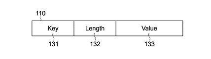
上述したように、リアルタイムメタデータには、例えば、LTC、ユーザビット、UMID、エッセンスマーク、ARIBメタデータ、又は、撮像が行われたビデオカメラの設定/制御情報等のデータが含まれる。 As described above, the real-time metadata includes, for example, data such as LTC, user bits, UMID, essence mark, ARIB metadata, or setting / control information of the video camera on which imaging has been performed.
本実施形態では、これらのデータは、図6に示されるように、キーデータ(Key)131、レングスデータ(Length)132、及び、バリューデータ(Value)133からなるKLV符号化されたデータ(以下、KLVデータと称する)である。このフォーマットは、SMPTE335M/RP214に準拠している。 In this embodiment, as shown in FIG. 6, these data are KLV encoded data (hereinafter referred to as “key data” 131), length data (Length) 132, and value data (Value) 133. , Referred to as KLV data). This format is compliant with SMPTE335M / RP214.
KLVデータ110のキーデータ131は、KLV符号化されたデータ項目を示す識別子である。この識別子には、SMPTEのメタデータ辞書に定義された、各種のデータ項目に対応する識別子が用いられる。KLVデータ110のレングスデータ132は、バリューデータ133の長さをバイト単位で示すデータである。KLVデータ110のバリューデータ133は、XML(eXtensible Markup Language)文書等のように、テキストデータ等のデータ本体からなるデータである。すなわち、KLVデータ110は、キーデータ131に示されるデータ項目のデータであり、レングスデータ132に示されるデータ長のデータであり、かつ、バリューデータ133に示されるデータを符号化したものである。
The
リアルタイムメタデータは、このようなデータ構造のKLVデータである、上述した各種のデータにより構成される。これらの複数のデータからなるリアルタイムメタデータは、その各データの内容から、大きく、必須部分と選択部分の2つに分けられる。必須部分は、全フレームに対応するリアルタイムメタデータに含まれるデータであり、LTC、ユーザビット、UMID、及びエッセンスマーク等のその他のKLVデータを含む各種のデータにより構成され、選択部分は、必要に応じてリアルタイムメタデータに含まれるデータで構成される。選択部分に含まれるデータとして、例えば、ARIBメタデータやビデオカメラの設定/制御情報等のデータ等がある。 Real-time metadata is composed of the various data described above, which is KLV data having such a data structure. The real-time metadata composed of the plurality of data is roughly divided into two parts, an essential part and a selection part, from the contents of each data. The essential part is the data included in the real-time metadata corresponding to all frames, and consists of various data including other KLV data such as LTC, user bits, UMID, and essence marks. Correspondingly, it is composed of data included in real-time metadata. Examples of data included in the selected portion include data such as ARIB metadata and video camera setting / control information.
なお、この必須部分と選択部分のそれぞれのデータ長は、いずれも予め定められた固定長である。また、リアルタイムメタデータは、SDI等の同期系通信インタフェースによるデータ転送に対応するために、リアルタイム性を要求されるデータである必要があるので、光ディスク31等に高速に書き込み及び読み出しができるように、必須部分(及び選択部分)をBIM(BInary Format for MPEG-7)形式の1つのファイルで構成する。
The data lengths of the essential part and the selection part are both fixed lengths determined in advance. In addition, since the real-time metadata needs to be data that requires real-time properties in order to support data transfer through a synchronous communication interface such as SDI, the real-time metadata can be written to and read from the
ここで、BIM形式のデータは、XLM形式のデータをバイナリデータに変換したものである。上述したリアルタイムメタデータに含まれる各種のデータは、XMLにより表現することも可能である。しかしながら、XMLの場合、そのデータ量が増大してしまうので、読み出し及び書き込み時間を短縮させることが望ましい(リアルタイム性が要求される)リアルタイムメタデータにおいては、XMLは不向きである。そこで、XLM表現と対等な情報を持つバイナリ表現であるBIMを用いることにより、リアルタイムメタデータのリアルタイム性を実現することができる。なお、リアルタイムメタデータにBIM形式のデータを用いることにより、リアルタイムメタデータの記録に必要な光ディスク31におけるデータ領域が削減されるだけでなく、書き込み時間及び読み出し時間を短縮することができ、さらに、書き込み及び読み出しの処理の際にデータを保持するメモリにおける記憶領域を削減することも可能であり、書き込み及び読み出しの処理速度を全体的に向上させるようにすることができる。
Here, the data in the BIM format is obtained by converting data in the XLM format into binary data. Various types of data included in the real-time metadata described above can also be expressed in XML. However, since the amount of data increases in the case of XML, it is desirable to shorten the read and write time (in real-time metadata required), XML is not suitable. Therefore, the real-time property of real-time metadata can be realized by using BIM, which is a binary representation having information equivalent to the XLM representation. By using BIM format data for real-time metadata, not only the data area in the
制御部40は、上述したように、リアルタイムメタデータ処理部66を制御し、データ量検出部62を介してリアルタイムメタデータ処理部66に供給された、以上のようなKLVデータからなるリアルタイムメタデータを、メモリコントローラ37を介して、光ディスク31に記録させる。
As described above, the
しかしながら、例えば、画像信号や音声信号が、撮像に用いられたビデオカメラ(図示せず)から、信号入出力装置51を介してディスク記録再生装置(ディスク装置)30に入力された場合、すなわち、撮像により得られた画像信号や音声信号が、メタデータを付加されることなく、ディスク記録再生装置30に供給された場合、その画像信号や音声信号には、LTC等のメタデータが付加されていない。例えば、ディスク記録再生装置30がビデオカメラと一体化している場合、撮像により得られた画像信号や音声信号は、リアルタイムメタデータ等が付加されるような処理が行われずに、データ変換部39に供給される。
However, for example, when an image signal or an audio signal is input from a video camera (not shown) used for imaging to the disk recording / reproducing device (disk device) 30 via the signal input /
そのような場合、制御部40は、データ変換部39のリアルタイムメタデータ処理部66を制御し、リアルタイムメタデータ処理部66が内蔵するLTCデータ処理部71に、LTCデータを生成するLTCデータ生成処理を実行させる。
In such a case, the
LTCデータ処理部71の制御部101は、LTCデータ生成処理を実行し、制御部40に制御されたリアルタイムメタデータ処理部66より、LTCデータの生成を指示されると、信号入出力装置51からデータ変換部39に供給される画像信号のフレームに同期してLTCデータを生成し、リアルタイムメタデータ処理部66に供給する。
The
図7のフローチャートを参照して、LTCデータ処理部71の制御部101によるLTCデータ生成処理について説明する。
With reference to the flowchart of FIG. 7, the LTC data generation processing by the
最初に、ステップS111において、制御部101は、リアルタイムメタデータ処理部66より、LTCデータ生成の開始指示を取得したか否かを判定し、取得したと判定するまで待機する。
First, in step S111, the
LTCデータ生成の開始指示を取得したと判定した場合、制御部101は、ステップS112に処理を進め、リアルタイムを用いたLTCを生成するか否かを判定する。
If it is determined that an instruction to start LTC data generation has been acquired, the
LTCデータの生成は、実際の時刻を用いて行う場合と、予め定められた初期値を用いて行う場合とがある。制御部40は、例えば、操作部41を介して受け付けられたそのような情報、すなわち、実際の時刻を用いてLTCデータを生成するか否かを指示する情報、さらに、実際の時刻を用いずにLTCデータを生成する場合、初期値が設定されたか否かを示す情報をデータ変換部39のリアルタイムメタデータ処理部66に供給する。
The generation of LTC data may be performed using actual time or may be performed using a predetermined initial value. For example, the
リアルタイムメタデータ処理部66は、LTCデータ生成の開始指示とともに、それらの情報をLTCデータ処理部71の制御部101に供給する。制御部101は、ステップS112において、供給されたその情報に基づいて、実際の時刻(リアルタイム)を用いたLTCを生成するか否かを判定する。
The real-time
ステップS112において、リアルタイムを用いたLTCを生成すると判定した場合、制御部101は、ステップS113に処理を進め、上述したように、LTC生成部102及びリアルタイムクロック105を制御することにより、リアルタイムクロックを用いて、同期信号に合わせてLTCデータを生成する。
If it is determined in step S112 that an LTC using real time is generated, the
すなわち、制御部101は、リアルタイムクロック105に同期信号を供給し、同期信号に合わせてリアルタイムに関する情報をLTC生成部102に供給させる。また、制御部101は、同期信号をLTC生成部102に供給し、LTC生成部102の動作を同期信号に同期させ、リアルタイムクロック105より供給されるリアルタイムに関する情報に基づいて、LTCデータを生成させる。
That is, the
ステップS113の処理が終了すると、制御部101は、ステップS114に処理を進め、LTC生成部102を制御し、生成したLTCデータをリアルタイムメタデータ処理部66に供給させることにより、メモリコントローラ37に供給させる。すなわち、リアルタイムメタデータ処理部66は、LTCデータ処理部71より供給されたLTCデータを、リアルタイムメタデータとして、メモリコントローラ37に供給する。
When the processing in step S113 is completed, the
LTCデータを供給させた制御部101は、ステップS115において、上述した制御信号や同期信号と同様にリアルタイムメタデータ処理部66より供給されたLTCデータ生成の終了指示を取得したか否かを判定する。制御部40は、操作部41を介して入力されたユーザの指示等に基づいて、LTCデータ生成の終了指示をデータ変換部39のリアルタイムメタデータ処理部66に供給する。リアルタイムメタデータ処理部66は、LTCデータ生成の終了指示を取得すると、その指示をLTCデータ処理部71の制御部101に供給する。制御部101は、ステップS115において、その指示を取得したか否かを判定する。
In step S115, the
ステップS115において、制御部101は、LTCデータ生成の終了指示を取得していないと判定した場合、ステップS113に処理を戻し、それ以降の処理を繰り返す。また、LTCデータ生成の終了指示を取得したと判定した場合、制御部101は、LTCデータ生成処理を終了する。
In step S115, when it is determined that the LTC data generation end instruction has not been acquired, the
ところで、ステップS112において、リアルタイムを用いずにLTCを生成すると判定した場合、制御部101は、ステップS116に処理を進め、上述したようにリアルタイムメタデータ処理部66より取得した情報に基づいて、初期値の設定が指示されたか否かを判定する。
By the way, when it determines with producing | generating LTC without using real time in step S112, the
初期値の設定が指示されていると判定した場合、制御部101は、ステップS117に処理を進め、初期値設定部103を制御し、LTCの初期値を指示された値に設定する。すなわち、この場合、制御部101は、初期値設定部103に初期値の指示に関する情報(指示された初期値)を初期値設定部103に供給し、LTCの初期値をその値に設定させる。初期値設定部103は、設定した初期値をLTC生成部102に供給する。初期値の設定が終了すると、制御部101は、ステップS119に処理を進める。
If it is determined that the setting of the initial value is instructed, the
また、ステップS116において、初期値の設定が指示されていないと判定した場合、制御部101は、ステップS118に処理を進め、初期値設定部103を制御し、LTCの初期値を「0」に設定する。すなわち、この場合、制御部101は、初期値設定部103に、値「0」の情報を供給し、LTCの初期値を「0」に設定させる。初期値設定部103は、設定した初期値をLTC生成部102に供給する。初期値の設定が終了すると、制御部101は,ステップS119に処理を進める。
If it is determined in step S116 that the setting of the initial value is not instructed, the
ステップS119において、制御部101は、LTC生成部102及びカウンタ104を制御し、カウンタ104を用いて、同期信号に合わせてLTCデータを生成させる。すなわち、カウンタ104は、制御部101より供給される同期信号に合わせて、カウント処理を行い、算出されたカウント値をLTC生成部102に順次供給する。LTC生成部102は、制御部101より供給される同期信号に同期して動作し、初期値設定部103より供給された初期値、及び、カウンタ104より供給されたカウンタ値を用いてLTCデータを生成する。
In step S119, the
ステップS119の処理が終了した制御部101は、ステップS120において、LTC生成部102を制御し、生成したLTCデータをリアルタイムメタデータ処理部66に供給させることにより、メモリコントローラ37に供給させる。すなわち、リアルタイムメタデータ処理部66は、LTCデータ処理部71より供給されたLTCデータを、リアルタイムメタデータとして、メモリコントローラ37に供給する。
The
LTCデータを供給させた制御部101は、ステップS121において、ステップS115の処理の場合と同様に、リアルタイムメタデータ処理部66より供給されたLTCデータ生成の終了指示を取得したか否かを判定する。制御部40は、操作部41を介して入力されたユーザの指示等に基づいて、LTCデータ生成の終了指示をデータ変換部39のリアルタイムメタデータ処理部66に供給する。リアルタイムメタデータ処理部66は、LTCデータ生成の終了指示を取得すると、その指示をLTCデータ処理部71の制御部101に供給する。制御部101は、ステップS121において、その指示を取得したか否かを判定する。
In step S121, the
ステップS121において、制御部101は、LTCデータ生成の終了指示を取得していないと判定した場合、ステップS119に処理を戻し、それ以降の処理を繰り返す。また、LTCデータ生成の終了指示を取得したと判定した場合、制御部101は、LTCデータ生成処理を終了する。
When determining in step S121 that the LTC data generation end instruction has not been acquired, the
上述したように生成され、メモリコントローラ37に供給されたLTCデータは、上述したように、リアルタイムメタデータとして処理され、音声データや画像データとともに、光ディスク31に記録される。
The LTC data generated and supplied to the
以上のように生成されたLTCデータをリアルタイムメタデータとしてエッセンスデータともに記録することにより、図1のディスク記録再生装置30は、後述するように、エッセンスデータ再生の際に、ユーザがより容易に再生制御処理を行うことができるようにすることができる。エッセンスデータとは、例えば画像データや音声データを含む編集対象のコンテンツデータである。
By recording the LTC data generated as described above together with the essence data as real time metadata, the disc recording / reproducing
なお、リアルタイムメタデータ処理部66は、LTCデータ処理部71又はデータ量検出部62より取得したLTCデータをメモリコントローラ37に供給するだけでなく、ノンリアルタイムメタデータ処理部67に供給する。ノンリアルタイムメタデータ処理部67は、取得したLTCデータを、内蔵するLTCデータ処理部72に供給する。また、ノンリアルタイムメタデータ処理部67は、制御部40より供給される制御信号、同期信号、又はFTCデータ等必要な情報をLTCデータ処理部72に供給する。なお、これらの情報は、画像データのフレーム毎に供給される。従って、LTCデータ処理部72は、LTC変化点テーブル作成処理を実行し、フレーム毎に供給されたこれらの情報に基づいてノンリアルタイムメタデータとしてのLTC変化点テーブルを生成する。
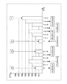
The real-time
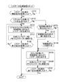
ノンリアルタイムメタデータ処理部67のLTCデータ処理部72による、LTC変化点テーブルの作成処理について説明する。まず図8に示すように、クリップ134が記録される途中でキューアップ処理要求、すなわちフレームの再生指示が発生しない場合における、LTC変化点テーブル124の作成処理について説明する。この場合、記録済みのクリップが有する全てのフレームのLTCデータに基づいて、LTC変化点テーブル124aが作成される。
An LTC change point table creation process by the LTC
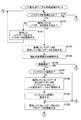
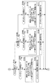
図9〜図11は、上記した場合におけるLTC変化点テーブル124aの作成処理の一例を示すフローチャートである。また、図12〜図17は、図9〜図11に示すステップを説明するための図である。 9 to 11 are flowcharts showing an example of processing for creating the LTC change point table 124a in the above case. Moreover, FIGS. 12-17 is a figure for demonstrating the step shown in FIGS. 9-11.
最初に、取得制御部111は、ステップS141において、LTCデータを取得したか否かを判定し、取得したと判定した場合、そのLTCデータ、及びそのLTCデータと同時に供給される、そのLTCデータに対応するFTCデータを判定処理部112に供給し、ステップS142に処理を進める。
First, in step S141, the
取得制御部111よりLTCデータを取得した判定処理部112は、データ管理部113を制御して、データ保持部114が保持しているLTCデータが存在するか否かを確認させる。データ管理部113は、この制御に基づいてデータ保持部114にアクセスし、LTCデータ121が保持されているか否かを確認し、その確認結果を判定処理部112に供給する。ステップS142において、判定処理部112は、供給された確認結果に基づいて、データ保持部114が保持しているLTCデータが存在するか否かを判定する。
The
例えば、ステップS141において取得制御部111がクリップの先頭フレームに対応するLTCデータを取得したところであり、データ保持部114には、LTCデータ121が保持されていないと判定した場合、判定処理部112は、ステップS143に処理を進め、取得したLTCデータ及びFTCデータを、データ管理部113を介してデータ保持部114に供給し、保持させる。データ保持部114は、データ管理部113を介して取得したLTCデータ及びFTCデータをその記憶領域に保持する。データ保持部114にLTCデータ及びFTCデータを保持させると、判定処理部112は、ステップS141に処理を戻し、次のフレームのLTCデータやFTCデータに対して、それ以降の処理を繰り返す。
For example, when the
また、ステップS142において、データ保持部114が保持しているLTCデータ121が存在すると判定した場合、判定処理部112は、ステップS144に処理を進め、データ管理部113を制御して、そのLTCデータ121をデータ保持部114より取得し、取得制御部111より供給されたLTCデータ(取得したLTCデータ)の値と、データ保持部114より取得したLTCデータ(保持しているLTCデータ)の値とを比較する。そして、判定処理部112は、ステップS145において、区間設定管理部115を制御して、区間設定保持部116に保持されている区間名123、すなわち、現在の区間設定(ステータス)を参照する。
If it is determined in step S142 that the
ステップS145の処理を終了した判定処理部112は、ステップS146に処理を進め、ステップS144において比較した比較結果に基づいて、取得したLTCデータの値が、保持しているLTCデータの値より1つ大きい(連続増加である)か否かを判定し、連続増加であると判定した場合、ステップS147に処理を進め、ステップS145において参照した参照結果に基づいて、現在の区間がインクリメント区間(ステータスがインクリメントである区間)であるか否かを判定する。
The
現在の区間がインクリメント区間でないと判定した場合、判定処理部112は、ステータス(すなわち、区間)が変化したと判定し、そのフレーム(保持しているLTCデータに対応するフレーム)をLTCの変化点とするために、ステップS148に処理を進め、データ管理部113を制御してデータ保持部114に保持されているLTCデータ121及びFTCデータ122を取得し、そのLTCデータ及びFTCデータにステータス情報(この場合、インクリメント)を付加する。そして、判定処理部112は、そのLTCデータ、FTCデータ、及びステータス情報をLTC変化点テーブルの要素として登録処理部117に供給する。登録処理部117は、そのLTC変化点テーブルの要素を、インクリメント点(ステータスがインクリメントである変化点)として、メモリ38に供給し、LTC変化点テーブルに登録する。
If it is determined that the current section is not an increment section, the
ステップS148の処理が終了すると、判定処理部112は、ステップS149において、今回判定されたステータスを、区間設定管理部115を介して区間設定保持部116に供給し、区間名123として記憶させることにより、現在の区間をインクリメント区間に設定し、ステップS150に処理を進める。また、ステップS147において、現在の区間がインクリメント区間であると判定した場合、判定処理部112は、ステップS148及びステップS149の処理を省略し、ステップS150に処理を進める。
When the process of step S148 is completed, the
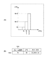
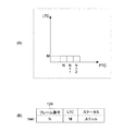
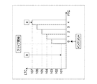
図12Aは、インクリメント区間におけるFTCとLTCの関係の例を示す図であり、横軸はフレームのFTCを示しており、縦軸はそのフレームのLTCを示している。図12Aにおいて、例えば、FTCの値が「N」のフレーム(フレーム番号Nのフレーム)のLTCの値は「M」であり、その次のフレーム(FTCの値が「N+1」のフレーム)のLTCの値は「M+1」であり、さらに次のフレーム(FTCの値が「N+2」のフレーム)のLTCの値は「M+2」である。このように、インクリメント区間においては、連続するフレームにおけるLTCの値は、FTCが1ずつ増加するとともに1ずつ増加する。 FIG. 12A is a diagram illustrating an example of the relationship between FTC and LTC in the increment interval, in which the horizontal axis indicates the FTC of the frame, and the vertical axis indicates the LTC of the frame. In FIG. 12A, for example, the LTC value of a frame with an FTC value of “N” (frame number N) is “M”, and the LTC of the next frame (frame with an FTC value of “N + 1”). The value of “M + 1” is “M + 1”, and the LTC value of the next frame (the frame whose FTC value is “N + 2”) is “M + 2”. Thus, in the increment interval, the LTC value in consecutive frames increases by 1 as FTC increases by 1.
例えば、ステータスが設定されていない(区間設定保持部116が区間名123を保持していない)、又は、設定されているステータスがインクリメントでない(区間設定保持部116が保持している区間名123の内容がインクリメントでない)場合に、図12Aに示されるようなフレーム群(LTCが連続増加するフレーム群)がデータ変換部39に入力されると、判定処理部112は、ステータスが「インクリメント」に変化した(区間が変わった)と判定し、それらの最初のフレームであるフレーム番号Nのフレームをインクリメント点として、図12Bに示されるようなLTC変化点テーブル124の要素141を作成する。
For example, the status is not set (the section setting holding unit 116 does not hold the section name 123), or the set status is not incremented (the
上述したように、LTC変化点テーブルの各要素は、そのLTC変化点のFTCを示す「フレーム番号」、そのLTC変化点のLTCを示す「LTC」、並びに、そのLTC変化点以降のフレームにおけるLTCの変化パターンの種類を示す「ステータス」の3つの項目からなり、図12Bに示される要素141の場合、項目「フレーム番号」の値は「N」となり、項目「LTC」の値は「M」となり、項目「ステータス」は、「インクリメント」となる。このような要素141を作成した判定処理部112は、これを登録処理部117に供給し、メモリ38に記憶されているLTC変化点テーブル124に登録させる。
As described above, each element of the LTC change point table includes the “frame number” indicating the FTC of the LTC change point, the “LTC” indicating the LTC of the LTC change point, and the LTC in the frames after the LTC change point. In the case of the
なお、区間設定保持部116が保持している区間名123の内容がインクリメントである場合に、図12Aに示されるようなフレーム群(LTCが連続増加するフレーム群)がデータ変換部39に入力されると、判定処理部112は、ステータスが変化していない(同じ区間が継続している)と判定し、要素141を作成しない(ステータスを更新しない)。
Note that when the content of the
ステップS150において、判定処理部112は、データ管理部113を制御して、今回、取得制御部111を介して取得したLTCデータ及びFTCデータをデータ保持部114に供給し、それらを用いてデータ保持部114に保持されているLTCデータ121及びFTCデータ122を更新させる。
In step S150, the
更新が終了すると、判定処理部112は、図11のステップS184に処理を進める。
When the update is completed, the
また、ステップS146において、取得したLTCデータの値が、保持しているLTCデータの値より1つ大きくない(連続増加でない)と判定した場合、判定処理部112は、図10のステップS161に処理を進める。
If it is determined in step S146 that the acquired LTC data value is not one larger than the retained LTC data value (not continuously increased), the
図10のステップS161において、判定処理部112は、図9のステップS144において比較した比較結果に基づいて、取得したLTCデータの値が、保持しているLTCデータの値より2つ以上大きいか否かを判定し、2以上増加していると判定した場合、ステップS162に処理を進め、図9のステップS145において参照した参照結果に基づいて、現在の区間がインクリース区間(ステータスがインクリースである区間)であるか否かを判定する。
In step S161 of FIG. 10, the
現在の区間がインクリース区間でないと判定した場合、判定処理部112は、ステータス(すなわち、区間)が変化したと判定し、そのフレーム(保持しているLTCデータに対応するフレーム)をLTCの変化点とするために、ステップS163に処理を進め、データ管理部113を制御してデータ保持部114に保持されているLTCデータ121及びFTCデータ122を取得し、そのLTCデータ及びFTCデータにステータス情報(この場合、インクリース)を付加する。そして、判定処理部112は、そのLTCデータ、FTCデータ、及びステータス情報をLTC変化点テーブルの要素として登録処理部117に供給する。登録処理部117は、そのLTC変化点テーブルの要素を、インクリース点(ステータスがインクリースである変化点)として、メモリ38に供給し、LTC変化点テーブルに登録する。
If it is determined that the current section is not an incremental section, the
ステップS163の処理が終了すると、判定処理部112は、ステップS164において、今回判定されたステータスを、区間設定管理部115を介して区間設定保持部116に供給し、区間名123として記憶させることにより、現在の区間をインクリース区間に設定し、図9のステップS150に処理を戻し、それ以降の処理を繰り返す。また、図10のステップS162において、現在の区間がインクリース区間であると判定した場合、判定処理部112は、ステップS163及びステップS164の処理を省略し、図9のステップS150に処理を戻す。
When the process of step S163 is completed, the
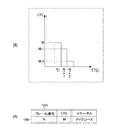
図13Aは、インクリース区間におけるFTCとLTCの関係の例を示す図であり、横軸はフレームのFTCを示しており、縦軸はそのフレームのLTCを示している。図13Aにおいて、例えば、FTCの値が「N」のフレーム(フレーム番号Nのフレーム)のLTCの値は「M」であり、その次のフレーム(FTCの値が「N+1」のフレーム)のLTCの値は「M+2」であり、さらに次のフレーム(FTCの値が「N+2」のフレーム)のLTCの値は「M+5」である。このように、インクリース区間においては、連続するフレームにおけるLTCの値は、FTCが1ずつ増加するとともに2以上ずつ増加する。 FIG. 13A is a diagram illustrating an example of the relationship between FTC and LTC in the increment section, in which the horizontal axis indicates the FTC of the frame, and the vertical axis indicates the LTC of the frame. In FIG. 13A, for example, the LTC value of a frame with an FTC value of “N” (frame number N) is “M”, and the LTC of the next frame (frame with an FTC value of “N + 1”). The value of is “M + 2”, and the LTC value of the next frame (the frame whose FTC value is “N + 2”) is “M + 5”. As described above, in the increment section, the LTC value in consecutive frames increases by 2 or more as FTC increases by 1.
例えば、ステータスが設定されていない(区間設定保持部116が区間名123を保持していない)、又は、設定されているステータスがインクリースでない(区間設定保持部116が保持している区間名123の内容がインクリースでない)場合に、図13Aに示されるようなフレーム群(LTCが2以上ずつ増加するフレーム群)がデータ変換部39に入力されると、判定処理部112は、ステータスが「インクリース」に変化した(区間が変わった)と判定し、それらの最初のフレームであるフレーム番号Nのフレームをインクリース点として、図13Bに示されるようなLTC変化点テーブル124の要素142を作成する。
For example, the status is not set (the section setting holding unit 116 does not hold the section name 123), or the set status is not an increment (the
図13Bに示される要素142の場合、項目「フレーム番号」の値は「N」となり、項目「LTC」の値は「M」となり、項目「ステータス」は、「インクリース」となる。このような要素142を作成した判定処理部112は、これを登録処理部117に供給し、メモリ38に記憶されているLTC変化点テーブル124に登録させる。
In the case of the
なお、区間設定保持部116が保持している区間名123の内容がインクリースである場合に、図13Aに示されるようなフレーム群(LTCが2以上ずつ増加するフレーム群)がデータ変換部39に入力されると、判定処理部112は、ステータスが変化していない(同じ区間が継続している)と判定し、要素142を作成しない(ステータスを更新しない)。
Note that when the content of the
また、ステップS161において、取得したLTCデータの値が、保持しているLTCデータの値より2以上増加していないと判定した場合、判定処理部112は、ステップS165に処理を進める。
If it is determined in step S161 that the acquired LTC data value has not increased by two or more than the retained LTC data value, the
ステップS165において、判定処理部112は、図9のステップS144において比較した比較結果に基づいて、取得したLTCデータの値が、保持しているLTCデータの値と同じであるか否かを判定し、LTCデータの値が変化しておらず、同じであると判定した場合、ステップS166に処理を進め、図9のステップS145において参照した参照結果に基づいて、現在の区間がスティル区間(ステータスがスティルである区間)であるか否かを判定する。
In step S165, the
現在の区間がスティル区間でないと判定した場合、判定処理部112は、ステータス(すなわち、区間)が変化したと判定し、そのフレーム(保持しているLTCデータに対応するフレーム)をLTCの変化点とするために、ステップS167に処理を進め、データ管理部113を制御してデータ保持部114に保持されているLTCデータ121及びFTCデータ122を取得し、そのLTCデータ及びFTCデータにステータス情報(この場合、スティル)を付加する。そして、判定処理部112は、そのLTCデータ、FTCデータ、及びステータス情報をLTC変化点テーブルの要素として登録処理部117に供給する。登録処理部117は、そのLTC変化点テーブルの要素を、スティル点(ステータスがスティルである変化点)として、メモリ38に供給し、LTC変化点テーブルに登録する。
If it is determined that the current section is not a still section, the
ステップS167の処理が終了すると、判定処理部112は、ステップS168において、今回判定されたステータスを、区間設定管理部115を介して区間設定保持部116に供給し、区間名123として記憶させることにより、現在の区間をスティル区間に設定し、図9のステップS150に処理を戻し、それ以降の処理を繰り返す。また、図10のステップS166において、現在の区間がスティル区間であると判定した場合、判定処理部112は、ステップS167及びステップS168の処理を省略し、図9のステップS150に処理を戻す。
When the process of step S167 ends, the
図14Aは、スティル区間におけるFTCとLTCの関係の例を示す図であり、横軸はフレームのFTCを示しており、縦軸はそのフレームのLTCを示している。図14Aにおいて、例えば、FTCの値が「N」のフレーム(フレーム番号Nのフレーム)も、その次のフレーム(FTCの値が「N+1」のフレーム)も、さらに次のフレーム(FTCの値が「N+2」のフレーム)も、LTCの値は「M」である。このように、スティル区間においては、連続するフレームにおけるLTCの値は、FTCが1ずつ増加しても変化しない。 FIG. 14A is a diagram illustrating an example of the relationship between FTC and LTC in the still section, in which the horizontal axis indicates the FTC of the frame, and the vertical axis indicates the LTC of the frame. In FIG. 14A, for example, a frame with an FTC value “N” (a frame with a frame number N), a next frame (a frame with an FTC value “N + 1”), and a next frame (with an FTC value of The value of LTC is “M” in the “N + 2” frame. Thus, in the still interval, the LTC value in consecutive frames does not change even if FTC increases by one.
例えば、ステータスが設定されていない(区間設定保持部116が区間名123を保持していない)、又は、設定されているステータスがスティルでない(区間設定保持部116が保持している区間名123の内容がスティルでない)場合に、図14Aに示されるようなフレーム群(LTCが変化しないフレーム群)がデータ変換部39に入力されると、判定処理部112は、ステータスが「スティル」に変化した(区間が変わった)と判定し、それらの最初のフレームであるフレーム番号Nのフレームをスティル点として、図14Bに示されるようなLTC変化点テーブル124の要素144を作成する。図14Bに示される要素144の場合、項目「フレーム番号」の値は「N」となり、項目「LTC」の値は「M」となり、項目「ステータス」は、「スティル」となる。このような要素144を作成した判定処理部112は、これを登録処理部117に供給し、メモリ38に記憶されているLTC変化点テーブル124に登録させる。
For example, the status is not set (the section setting holding unit 116 does not hold the section name 123), or the set status is not still (the
なお、区間設定保持部116が保持している区間名123の内容がスティルである場合に、図14Aに示されるようなフレーム群(LTCが変化しないフレーム群)がデータ変換部39に入力されると、判定処理部112は、ステータスが変化していない(同じ区間が継続している)と判定し、要素144を作成しない(ステータスを更新しない)。
When the content of the
また、ステップS165において、取得したLTCデータの値が、保持しているLTCデータの値と同じではない(すなわち、減少している)と判定した場合、判定処理部112は、ステップS169に処理を進める。
If it is determined in step S165 that the acquired LTC data value is not the same as the retained LTC data value (ie, decreases), the
ステップS169において、判定処理部112は、図9のステップS145において参照した参照結果に基づいて、現在の区間がディクリース区間(ステータスがディクリースである区間)であるか否かを判定する。
In step S169, the
現在の区間がディクリース区間でないと判定した場合、判定処理部112は、ステータス(すなわち、区間)が変化したと判定し、そのフレーム(保持しているLTCデータに対応するフレーム)をLTCの変化点とするために、ステップS170に処理を進め、データ管理部113を制御してデータ保持部114に保持されているLTCデータ121及びFTCデータ122を取得し、そのLTCデータ及びFTCデータにステータス情報(この場合、ディクリース)を付加する。そして、判定処理部112は、そのLTCデータ、FTCデータ、及びステータス情報をLTC変化点テーブルの要素として登録処理部117に供給する。登録処理部117は、そのLTC変化点テーブルの要素を、ディクリース点(ステータスがディクリースである変化点)として、メモリ38に供給し、LTC変化点テーブルに登録する。
When it is determined that the current section is not a decrease section, the
ステップS170の処理が終了すると、判定処理部112は、ステップS171において、今回判定されたステータスを、区間設定管理部115を介して区間設定保持部116に供給し、区間名123として記憶させることにより、現在の区間をスティル区間に設定し、図9のステップS150に処理を戻し、それ以降の処理を繰り返す。また、図10のステップS169において、現在の区間がディクリース区間であると判定した場合、判定処理部112は、ステップS170及びステップS171の処理を省略し、図9のステップS150に処理を戻す。
When the process of step S170 ends, the
図15Aは、ディクリース区間におけるFTCとLTCの関係の例を示す図であり、横軸はフレームのFTCを示しており、縦軸はそのフレームのLTCを示している。図15Aにおいて、例えば、FTCの値が「N」のフレーム(フレーム番号Nのフレーム)のLTCの値は「M」であり、その次のフレーム(FTCの値が「N+1」のフレーム)のLTCの値は「M−1」であり、さらに次のフレーム(FTCの値が「N+2」のフレーム)のLTCの値は「M−3」である。このように、ディクリース区間においては、連続するフレームにおけるLTCの値は、FTCが1ずつ増加するとともに1以上ずつ減少する。 FIG. 15A is a diagram illustrating an example of the relationship between FTC and LTC in the decrease interval, in which the horizontal axis indicates the FTC of the frame, and the vertical axis indicates the LTC of the frame. In FIG. 15A, for example, the LTC value of the frame with the FTC value “N” (frame number N) is “M”, and the LTC of the next frame (the frame with the FTC value “N + 1”). The value of is “M−1”, and the LTC value of the next frame (the frame whose FTC value is “N + 2”) is “M-3”. Thus, in the decrease interval, the LTC value in consecutive frames decreases by 1 or more as FTC increases by 1.
例えば、ステータスが設定されていない(区間設定保持部116が区間名123を保持していない)、又は、設定されているステータスがディクリースでない(区間設定保持部116が保持している区間名123の内容がディクリースでない)場合に、図15Aに示されるようなフレーム群(LTCが1以上ずつ減少するフレーム群)がデータ変換部39に入力されると、判定処理部112は、ステータスが「ディクリース」に変化した(区間が変わった)と判定し、それらの最初のフレームであるフレーム番号Nのフレームをディクリース点として、図15Bに示されるようなLTC変化点テーブル124の要素146を作成する。図15Bに示される要素146の場合、項目「フレーム番号」の値は「N」となり、項目「LTC」の値は「M」となり、項目「ステータス」は、「ディクリース」となる。このような要素146を作成した判定処理部112は、これを登録処理部117に供給し、メモリ38に記憶されているLTC変化点テーブル124に登録させる。
For example, the status is not set (the section setting holding unit 116 does not hold the section name 123), or the set status is not “decrease” (the
なお、区間設定保持部116が保持している区間名123の内容がディクリースである場合に、図15Aに示されるようなフレーム群(LTCが減少するフレーム群)がデータ変換部39に入力されると、判定処理部112は、ステータスが変化していない(同じ区間が継続している)と判定し、要素146を作成しない(ステータスを更新しない)。
When the content of the
また、図9のステップS141において、例えばエッセンスデータの入力が停止し、本来取得すべきタイミングにおいてLTCデータを取得していないと判定した場合、取得制御部111は、図11のステップS181に処理を進める。図11のステップS181において、判定処理部112は、クリップが終了したと判定し、データ管理部113を制御してデータ保持部114に保持されているLTCデータ121及びFTCデータ122を取得し、そのLTCデータ及びFTCデータにステータス情報(この場合、エンド)を付加する。そして、判定処理部112は、そのLTCデータ、FTCデータ、及びステータス情報をLTC変化点テーブルの要素として登録処理部117に供給する。登録処理部117は、そのLTC変化点テーブルの要素を、エンド点(ステータスがエンドである変化点)として、メモリ38に供給し、LTC変化点テーブルに登録する。
Further, in step S141 in FIG. 9, for example, when the input of essence data is stopped and it is determined that the LTC data is not acquired at the timing to be originally acquired, the
図16Aは、エンド点におけるFTCとLTCの関係の例を示す図であり、横軸はフレームのFTCを示しており、縦軸はそのフレームのLTCを示している。図16Aにおいて、例えば、FTCの値が「N」のフレーム(フレーム番号Nのフレーム)のLTCの値は「M」であり、その次のフレーム(FTCの値が「N+1」のフレーム)のLTCの値は「M+1」であり、さらに次のフレーム(FTCの値が「N+2」のフレーム)のLTCの値は「M+2」である。すなわち、この区間のステータスはインクリメントであり、例えば、図16Bに示されるように、LTC変化点テーブル124には、要素148が登録されている。図16Bに示される要素148の場合、項目「フレーム番号」の値は「N」となり、項目「LTC」の値は「M」となり、項目「ステータス」は、「インクリメント」となる。
FIG. 16A is a diagram illustrating an example of the relationship between FTC and LTC at an end point, the horizontal axis indicates the FTC of the frame, and the vertical axis indicates the LTC of the frame. In FIG. 16A, for example, the LTC value of a frame with an FTC value of “N” (frame number N) is “M”, and the LTC of the next frame (a frame with an FTC value of “N + 1”). The value of “M + 1” is “M + 1”, and the LTC value of the next frame (the frame whose FTC value is “N + 2”) is “M + 2”. That is, the status of this section is increment, and, for example, as shown in FIG. 16B, the
このような場合に、フレーム番号N+2のフレームでクリップが終了し、取得制御部111がフレーム番号N+2のフレームの、次のフレームを取得していないと、判定処理部112は、クリップが終了したと判定し、データ保持部114に保持されている最後のフレームであるフレーム番号N+2のフレームをエンド点として、図16Bに示されるようなLTC変化点テーブル124の要素149を作成する。図16Bに示される要素149の場合、項目「フレーム番号」の値は「N+2」となり、項目「LTC」の値は「M+2」となり、項目「ステータス」は、「エンド」となる。
In such a case, if the clip ends at frame number N + 2 and the
以上のように、LTC変化点テーブルにエンド点を登録した判定処理部112は、ステップS184に処理を進める。
As described above, the
また、上述したように、図9及び図10の処理を行い、図9のステップS150を終了した判定処理部112は、図11のステップS182に処理を進め、登録処理部117を制御してメモリ38の空き容量を調査させ、LTC変化点テーブル124にさらに2つ以上の要素を登録可能か否かを判定する。空き容量が十分にあり、LTC変化点テーブル124にさらに2つ以上の要素を登録可能であると判定した場合、判定処理部112は、図9のステップS141に処理を戻し、次のフレームに対してそれ以降の処理を繰り返す。
Further, as described above, the
また、図11のステップS182において、メモリ38の空き容量が十分でなく、LTC変化点テーブル124に、あと1つの要素しか追加できないと判定した場合、判定処理部112は、ステップS183に処理を進め、今回取得制御部111を介して取得したLTCデータ及びFTCデータにステータス情報(この場合、オーバ)を付加する。そして、判定処理部112は、そのLTCデータ、FTCデータ、及びステータス情報をLTC変化点テーブルの要素として登録処理部117に供給する。登録処理部117は、そのLTC変化点テーブルの要素を、オーバ点(ステータスがオーバである変化点)として、メモリ38に供給し、LTC変化点テーブル124に登録する。
If it is determined in step S182 in FIG. 11 that the free space of the
図17Aは、オーバ点におけるFTCとLTCの関係の例を示す図であり、横軸はフレームのFTCを示しており、縦軸はそのフレームのLTCを示している。図17Aにおいて、例えば、FTCの値が「N」のフレーム(フレーム番号Nのフレーム)のLTCの値は「M」であり、その次のフレーム(FTCの値が「N+1」のフレーム)のLTCの値は「M+1」であり、さらに次のフレーム(FTCの値が「N+2」のフレーム)のLTCの値は「M+2」であり、さらに次のフレーム(FTCの値が「N+3」のフレーム)のLTCの値は「M+3」であり、さらに次のフレーム(FTCの値が「N+4」のフレーム)のLTCの値は「M+4」である。すなわち、この区間のステータスはインクリメントであり、例えば、図17Bに示されるように、LTC変化点テーブル124には、要素150が登録されている。図17Bに示される要素150の場合、項目「フレーム番号」の値は「N」となり、項目「LTC」の値は「M」となり、項目「ステータス」は、「インクリメント」となる。
FIG. 17A is a diagram showing an example of the relationship between FTC and LTC at the over point, the horizontal axis shows the FTC of the frame, and the vertical axis shows the LTC of the frame. In FIG. 17A, for example, the LTC value of a frame with an FTC value of “N” (frame number N) is “M”, and the LTC of the next frame (frame with an FTC value of “N + 1”). The value of M is “M + 1”, the LTC value of the next frame (the frame with the FTC value “N + 2”) is “M + 2”, and the next frame (the frame with the FTC value “N + 3”). The LTC value is “M + 3”, and the LTC value of the next frame (the frame whose FTC value is “N + 4”) is “M + 4”. That is, the status of this section is increment, and for example, as shown in FIG. 17B, the
このような場合において、フレーム番号N+2のフレームのLTCデータ及びFTCデータを取得したときに、LTC変化点テーブル124にあと1つの要素しか追加できないと判定すると、判定処理部112は、今回取得制御部111を介して取得した最後のフレームであるフレーム番号N+2のフレームをオーバ点として、図17Bに示されるようなLTC変化点テーブル124の要素151を作成する。図17Bに示される要素149の場合、項目「フレーム番号」の値は「N+2」となり、項目「LTC」の値は「M+2」となり、項目「ステータス」は、「オーバ」となる。
In such a case, when the LTC data and the FTC data of the frame with the frame number N + 2 are acquired, if it is determined that only one more element can be added to the LTC change point table 124, the
以上のように、LTC変化点テーブルにオーバ点を登録させた判定処理部112は、ステップS184に処理を進める。
As described above, the
ステップS184において、LTCデータ処理部72は、終了処理を行い、LTC変化点テーブル作成処理を終了する。なお、このLTC変化点テーブル作成処理は、クリップがデータ変換部39に入力される度に実行される。
In step S184, the LTC
以上のように作成され、メモリ38に保持されているLTC変化点テーブル124aは、図5のステップS11の処理において、ノンリアルタイムメタデータとして読み出され、光ディスク31に記録される。
The LTC change point table 124a created as described above and held in the
このように、リアルタイムメタデータに含まれるLTCより、その変化点をテーブル化したLTC変化点テーブル124aを作成し、ノンリアルタイムメタデータとして記録することにより、図1のディスク記録再生装置30は、ユーザがより容易に再生制御処理を行うことが可能となる。
As described above, by creating the LTC change point table 124a in which the change points are tabulated from the LTC included in the real time metadata and recording it as non-real time metadata, the disc recording / reproducing
なお本実施形態では、以上のように光ディスク31に記録されたデータは、例えばUDF(Universal Disk Format)等のファイルシステムによって、ディレクトリ構造のファイル単位で管理される。なお、光ディスク31においてファイルを管理するファイルシステムは、UDFに限らず、例えば、ISO9660(International Organization for Standardization 9660)等、図1のディスク記録再生装置30が対応できるファイルシステムであればどのようなものであってもよい。また、光ディスク31の代わりにハードディスク等の磁気ディスクを用いた場合、ファイルシステムとして、FAT(File Allocation Tables)、NTFS(New Technology File System)、HFS(Hierarchical File System)、又はUFS(Unix(登録商標)(R) File System)等を用いてもよい。また、専用のファイルシステムを用いるようにしてもよい。
In the present embodiment, the data recorded on the
図18は、XMLで記述されたノンリアルタイムメタデータファイルに含まれるLTC変化点テーブル124aの記述例を示す図である。本実施形態では、ノンリアルタイムメタデータファイルは、汎用性を持たせるためにXML形式で記述される。一方、リアルタイムメタデータファイルは、再生処理の処理時間や処理に必要な負荷を軽減させるために、XML形式のファイルをコンパイルしたBIM(BInary format for MPEG-7 data)形式のファイルである。なお、図18において、各行頭の数字は、説明の便宜上付加したものであり、XML記述の一部ではない。 FIG. 18 is a diagram illustrating a description example of the LTC change point table 124a included in the non-real-time metadata file described in XML. In the present embodiment, the non-real time metadata file is described in the XML format in order to have versatility. On the other hand, the real-time metadata file is a BIM (BInary format for MPEG-7 data) format file obtained by compiling an XML format file in order to reduce the processing time of the playback processing and the load necessary for the processing. In FIG. 18, the numbers at the beginning of each line are added for convenience of explanation, and are not part of the XML description.
図18の1行目の「<LtcChangeTable tcFps="30">」の記述は、LTC変化点テーブルの記述の開始を示す開始タグであり、「tcFps="30"」の記述は、このLTC変化点テーブルにおいて、タイムコードは、30フレーム毎秒として記述されていることを示している。 The description of “<LtcChangeTable tcFps =“ 30 ”>” on the first line in FIG. 18 is a start tag indicating the start of description of the LTC change point table, and the description of “tcFps =“ 30 ”” is the LTC change. In the point table, it is shown that the time code is described as 30 frames per second.
2行目乃至12行目には、LTCの変化点を示す各要素が示されている。なお、2行目乃至12行目において、「frameCount=" "」の記述は、フレーム番号、すなわち、FTCの値を示しており、「value=" "」の記述は、そのフレームのLTCの値を示しており、「status=" "」の記述は、そのフレームのステータスを示している。 In the second to twelfth lines, elements indicating LTC change points are shown. In the second to twelfth lines, the description “frameCount =“ ”” indicates the frame number, that is, the FTC value, and the description “value =“ ”indicates the LTC value of the frame. The description “status =“ ”” indicates the status of the frame.
例えば、2行目の「<LtcChange frameCount="0" value="55300201" status="increment"/>」の記述の場合、この変化点は、フレーム番号「0」のフレームであり、そのLTCは「55300201」であり、このフレームより開始される区間のステータスが「インクリメント」であることを示している。以下、3行目乃至12行目の記述も、各値は異なるが、構成は基本的に2行目の場合と同様であるので、その説明を省略する。 For example, in the case of the description of “<LtcChange frameCount =“ 0 ”value =” 55300201 ”status =“ increment ”/>” on the second line, the change point is the frame with frame number “0”, and the LTC is “55300201”, indicating that the status of the section starting from this frame is “increment”. In the following description, the values in the third to twelfth lines are different from each other, but the configuration is basically the same as that in the second line, and the description thereof is omitted.
13行目の「</LtcChangeTable>」は、LTC変化点テーブル124aの記述の終了を示す終了タグである。 “</ LtcChangeTable>” on the 13th line is an end tag indicating the end of the description of the LTC change point table 124a.
例えば、ユーザがLTCを用いて表示するフレームを指示する場合、図1のディスク記録再生装置30は、ノンリアルタイムメタデータファイルより、図18に示されるように記述されたLTC変化点テーブルを読み込み、この記述に基づいて、指定されたフレームを検索し、表示する。このようにすることにより、ディスク記録再生装置30は、各フレームに対応付けられたリアルタイムメタデータに記述されているLTC群より目的のLTC(フレーム)を検索するよりも、容易に目的のフレームを検索することができる。
For example, when the user designates a frame to be displayed using LTC, the disc recording / reproducing
なお、図1に示されるディスク記録再生装置30は、上述した以外にも、例えば、図19に示されるように、撮像部302を有するカムコーダ300のディスク記録部301としてもよい。この場合、信号入出力装置51の代わりに撮像部302がディスク記録部301に接続され、撮像部302のカメラにより撮像された画像データや、撮像部302のマイクロホンにより集音された音声データ等からなるエッセンスデータがディスク記録部301入力される。ディスク記録部301は、その構成が上述したディスク記録再生装置30の場合と同様であり、ディスク記録再生装置30と同様に動作して、撮像部302より供給されたエッセンスデータやそのエッセンスデータに付加されるメタデータを光ディスク31に記録する。
In addition to the above, the disc recording / reproducing
次に、図20に示すように、クリップ134が記録される途中でキューアップ処理要求、すなわちフレームの再生指示が発生した場合における、LTC変化点テーブル124(124c)の作成処理について説明する。図21は、上記した場合におけるLTC変化点テーブル124b(124c)の作成処理の一例を示すシーケンス図である。
Next, as shown in FIG. 20, a process for creating the LTC change point table 124 (124c) when a cue-up process request, that is, a frame playback instruction is generated while the
図21に示すように、リアルタイムメタデータ処理部66(以下RT部66と記載する)からLTC変化点作成処理要求が所定のタイミングで出力される(ステップS201〜S203)。本実施形態では、複数のフレームのうち所定の数のフレームを有するフレーム群ごとにLTCがノンリアルタイムメタデータ処理部67(以下NRT部67と記載する)に出力され、当該フレーム群ごとにLTC変化点作成処理要求が出力される。フレーム群に含まれるフレームの数は、30フレーム等のフレーム数で規定されてもよいし、所定の長さの再生時間により規定されてもよい。 As shown in FIG. 21, an LTC change point creation processing request is output at a predetermined timing from the real-time metadata processing unit 66 (hereinafter referred to as the RT unit 66) (steps S201 to S203). In the present embodiment, the LTC is output to the non-real-time metadata processing unit 67 (hereinafter referred to as the NRT unit 67) for each frame group having a predetermined number of frames among a plurality of frames, and the LTC change is performed for each frame group. A point creation processing request is output. The number of frames included in the frame group may be defined by the number of frames such as 30 frames, or may be defined by a reproduction time having a predetermined length.
RT部66から出力された変化点作成処理要求は、メッセージキュー160に蓄積される。蓄積された変化点作成処理要求は、NRT部67によりLTC変化点作成処理通知として読み出される(ステップS204)。そして当該変化点作成通知により指定されたフレーム郡について、図9〜図11で説明したLTC変化点作成処理が実行される(ステップ205)。図8で説明したクリップ134全体についてのLTC変化点テーブル124aが作成される場合は、順次、フレーム群ごとのLTC作成処理通知がメッセージキュー160から読み出されることになる(ステップS206及びS207)。そして各フレーム群に対してLTC変化点作成処理が実行される(ステップ208及びS209)。
The change point creation processing request output from the
ステップS205にて1つのフレーム群についてLTC変化点テーブルが作成された場合、図20に示すように、当該フレーム群の最後のフレームのLTCデータ、FTCデータ及びステータス情報が保持される(符号L)。次のフレーム群についてLTC変化テーブル作成処理が実行される場合には(ステップS208)、上記の保持されたデータが用いられて、クリップ全体に対するLTC変化テーブル124aの作成処理が進む。 When the LTC change point table is created for one frame group in step S205, the LTC data, FTC data, and status information of the last frame of the frame group are held as shown in FIG. . When the LTC change table creation process is executed for the next frame group (step S208), the above-mentioned retained data is used to proceed with the creation process of the LTC change table 124a for the entire clip.
ここで図21に示すように、LTC変化点テーブル作成処理の途中で、キューアップ処理部355にLTCキューアップ要求が出力されたとする(ステップS210)。そうするとキューアップ処理部355からNRT部67に、フレームの再生指示としての、キューアップ地点探索指示が出力される(ステップS211)。キューアップ地点探索指示は、第1の位置情報としてのLTCデータを用いたフレームの再生指示である。
Here, as shown in FIG. 21, it is assumed that an LTC queue-up request is output to the queue-up
本実施形態では、LTCキューアップ要求を受けたキューアップ処理部355により、所定のタイミングで、NRT部67にキューアップ地点探索指示が出力される。しかしながらNRT部67は、1つのフレーム群についてLTC変化点テーブル124bが作成されメモリ38に書き込まれている間は、キューアップ地点探索指示を無効化する。そして1つのフレーム群についてのLTC変化点テーブル124bの作成処理が完了した後に、キューアップ地点探索指示を有効にする。
In this embodiment, the cue-
このようなデータ処理は、例えば図示しないメッセージキューを用いることで実現可能である。例えばキューアップ処理部355からのキューアップ地点探索指示がメッセージキューに蓄積される。NRT部67は、1つのフレーム群についてのLTC変化点テーブル124bの作成処理が完了した後に、メッセージキューから地点探索指示を読み出す。このように、RT部66とNRT部67との間のデータ処理、及びNRT部67とキューアップ処理部68とのデータ処理を、メッセージキューを用いて構成することで、システムを複雑にすることなく容易に操作性のよいコンテンツデータの再生システムを構築することができる。しかしながら、他の方法でシステムが構築されてもよい。
Such data processing can be realized by using, for example, a message queue (not shown). For example, a queue-up point search instruction from the queue-up
ステップS205のLTC変化点テーブルの作成処理が完了した場合、NRT部67は、キューアップ地点探索指示の読み出し処理を優先的に実行する。そして地点探索指示が出力されておらず当該指示の読み出しができなかった場合に、メッセージキュー160からLTC変化点テーブル作成処理通知を読み出す。すなわち本実施形態では、フレームの再生指示であるキューアップ地点探索指示の発生時に、メモリ38へのLTC変化点テーブル124bの書き込みが規制される。
When the LTC change point table creation process of step S205 is completed, the
キューアップ地点探索指示を受けたNRT部67は、LTCキューアップ地点探索処理を実行する(ステップS212)。地点探索処理は、地点探索指示をもとに図20に示すLTC変化点テーブル124cを参照して、当該地点探索指示に対応するフレームである再生フレームの、第2の位置情報であるFTCを特定する処理である。すなわちNRT部67は、特定部として機能する。LTCキューアップ地点探索処理については後述する。
Receiving the cue-up point search instruction, the
図21に示すステップS205の変化点テーブル作成処理により書き込まれたLTC変化点テーブル124bは、いわゆる未完成のテーブル情報である。すなわちクリップ134全体に対するLTC変化テーブル124aとして書き込み処理が完了したテーブル情報でない。本実施形態に係る排他処理部118は、このいわゆる未完成の変化点テーブル124bの情報を、キューアップ地点探索処理において参照可能なLTC変化点テーブル124cとする。この処理についても後述する。
The LTC change point table 124b written by the change point table creation process in step S205 shown in FIG. 21 is so-called incomplete table information. That is, it is not table information for which writing processing has been completed as the LTC change table 124a for the
ステップS212の地点探索処理により特定された再生フレームのFTCデータが、LTCキューアップ地点としてキューアップ処理部に返される(ステップS213)。そしてキューアップ処理部により、当該FTCデータが、ステップS210のキューアップ要求に応答する情報として出力される(ステップS214)。 The FTC data of the reproduction frame specified by the point search process in step S212 is returned to the cue-up processing unit as an LTC cue-up point (step S213). The queue-up processing unit outputs the FTC data as information in response to the queue-up request in step S210 (step S214).
ステップS206及びS207にて、NRT部67により、変化点テーブル作成処理通知が読み出され、LTC変化点テーブル作成処理が再開される。この地点探索処理から、LTC変化点テーブル作成処理の切り替えについても、後述する。
In steps S206 and S207, the
以上において説明したLTC変化点テーブル124の具体的な使用方法の例について説明する。 An example of a specific method of using the LTC change point table 124 described above will be described.
図22は、光ディスク31に記録されているエッセンスデータを編集し、その編集結果を他の光ディスク31に記録する編集システムの例を示す図である。
FIG. 22 is a diagram showing an example of an editing system that edits the essence data recorded on the
図22において、編集システム310は、互いにネットワーク322により接続されている2台のディスク記録再生装置321及び323、並びにエッセンスデータの編集を制御する編集制御装置324よりなる。ネットワーク322を介して接続されたディスク記録再生装置323及び編集制御装置324が、本実施形態に係る情報処理装置330として機能する。しかしながら、以下で説明するディスク記録再生装置323及び編集制御装置324が一体的に構成されたコンピュータ等の装置が本技術の一実施形態に係る情報処理装置として用いられてもよい。
22, the
ディスク記録再生装置321は、光ディスク31に対応するドライブ321Aを備えている。そして、当該ドライブ321Aに装着された光ディスク31に記録されているエッセンスデータ等を再生し、ネットワーク322を介してディスク記録再生装置323に供給する。
The disc recording / reproducing
ネットワーク322は、インターネットやイーサネット(登録商標)(Ethernet(登録商標)(R))等に代表されるネットワークであり、ディスク記録再生装置321、ディスク記録再生装置323、及び編集制御装置324が接続されており、これらの装置間において授受される各種のデータが伝送される。
The
ディスク記録再生装置323は、ドライブ323A及びモニタ323Bを有しており、ネットワーク322を介して接続された編集制御装置324に制御されて、ネットワーク322を介して供給されたエッセンスデータ等をドライブ323Aに装着されている光ディスク31に記録したり、記録された画像データに対応する画像をモニタ323Bに表示したりする。
The disc recording / reproducing
編集制御装置324は、ネットワーク322を介してディスク記録再生装置323を制御し、ディスク記録再生装置323に供給されるエッセンスデータを光ディスク31に記録させる。また当該エッセンスデータに対して編集処理を実行する。また、編集制御装置324は、ユーザインタフェースとして、ユーザがLTCを指定する場合に操作するテンキーであるLTC入力用キー324A、及び入力されたLTCを表示する、入力LTC確認用の表示部324Bを備えている。
The
なお、ディスク記録再生装置323は、図1に示されるディスク記録再生装置30と基本的に同様の構成であり、同様の操作を行うが、図1の信号入出力装置51の代わりに通信部を備え、ネットワークを介して他の装置と通信を行い、エッセンスデータ等の各種のデータを授受できるようになされている。
The disc recording / reproducing
図23は、図22に示す編集制御装置324の内部の構成例を示す模式的な図である。
FIG. 23 is a schematic diagram illustrating an internal configuration example of the
図23において、編集制御装置324のCPU(Central Processing Unit)331は、ROM(Read Only Memory)332に記憶されているプログラムに従って各種の処理を実行する。RAM(Random Access Memory)333には、CPU331が各種の処理を実行する上において必要なデータやプログラムなどが適宜記憶される。
In FIG. 23, a CPU (Central Processing Unit) 331 of the
再生制御部334は、通信部344を介してディスク記録再生装置323の再生処理を制御する処理を行う。例えば、再生制御部334は、ディスク記録再生装置323を制御して、ドライブ323Aに装着されている光ディスク31に記録されるエッセンスデータ等のクリップの再生を実行させたり、ユーザにより指定されたLTCに対応するフレーム画像をモニタ323Bに表示させたりする。
The
編集制御部335は、通信部344を介してディスク記録再生装置323を制御して、エッセンスデータの編集処理を制御する処理を行う。例えば、編集制御部335は、ネットワーク322を介してディスク記録再生装置323を制御し、光ディスク31に記録されたクリップの再生(通常再生、早送り再生、巻き戻し再生、一時停止、停止等)を実行させ、その再生されたクリップに対応する画像をモニタ323Bに表示させるとともに、それを図示しない他の記録媒体に編集データとして記録させる。
The
CPU331、ROM332、RAM333、再生制御部334、及び編集制御部335は、バス336を介して相互に接続されている。
The
バス336には、さらに、入出力インタフェース340が接続されている。入出力インタフェース340は、LTC入力用テンキーや各種の指示入力用ボタン等よりなる入力部341が接続され、入力部341に入力された信号をCPU331に出力する。また、入出力インタフェース340には、表示部324Bなどを含む出力部342も接続されている。
An input /
さらに、入出力インタフェース340には、ハードディスク等の磁気ドライブやEEPROM(Electronically Erasable and Programmable Read Only Memory)などから構成される記憶部343、及び、ネットワーク322を介してディスク記録再生装置321やディスク記録再生装置323とデータの通信を行う通信部344も接続されている。ドライブ345には、磁気ディスク、光ディスク、光磁気ディスク、又は半導体メモリなどの記録媒体からなるリムーバブルメディア346が適宜装着される。ドライブ345は、ドライブ345に装着されたリムーバブルメディア346に記録されたプログラムやデータの読み出しを制御する。
Further, the input /
図24は、図23の再生制御部334の構成例を示す模式的な図である。図24において、再生制御部334は、再生制御部334の全体を制御する制御部351、入力部341を介して入力されたユーザ入力を受け付ける入力受付処理部352、通信部344を介して取得されたLTCやFTC等のノンリアルタイムメタデータ(NRT)を取得する情報取得部353、情報取得部353により取得されたノンリアルタイムメタデータを保持する保持部354、モニタに表示させるフレーム画像を、LTCを用いて指定するキューアップ処理を制御するキューアップ処理部355、並びに、制御部351より供給された各種の命令情報を出力する命令処理部356を有している。
FIG. 24 is a schematic diagram illustrating a configuration example of the
制御部351は、図示せぬROMやRAMを内蔵し、各種のプログラムを実行することにより、再生制御部334の各部の動作を制御する。入力受付処理部352は、入力部341を介して入力されたユーザ入力の受付を制御し、受け付けたユーザ入力を制御部351に供給する。
The
情報取得部353は、制御部351に制御され、例えば、通信部344を介して供給されたノンリアルタイムメタデータ(NRT)を取得すると、取得したノンリアルタイムメタデータを保持部354に供給して保持させる。
When the
保持部354は、ハードディスクや半導体メモリ等の記憶媒体からなり、情報取得部353より供給されるノンリアルタイムメタデータを保持する。すなわち、保持部354は、ノンリアルタイムメタデータに含まれるLTC変化点テーブル124を保持する。ここでいうLTC変化点テーブル124は、ディスク記録再生装置323により生成されたLTC変化点テーブルである。すなわち、図20で示す、記録されたクリップ全体についての変化点テーブル124aと、クリップの記録途中で参照可能とされた変化点テーブル124cとを含む。
The holding
キューアップ処理部355は、クリップの再生に関する処理の内、ユーザがLTCを用いてモニタに表示させるフレーム画像のフレーム番号を指定するキューアップに関する処理を行う。例えば、キューアップ処理部355は、制御部351よりユーザに指定されたLTCが供給されると、保持部354にアクセスし、保持部354が保持しているLTC変化テーブル124を参照し、指定されたLTCに対応するフレームを特定し、そのフレームのFTC(フレーム番号)の情報を制御部351に供給する。
The cue-
命令処理部356は、制御部351より供給された命令情報等を、通信部344を介して、ディスク記録再生装置323等に供給する。
The
次に図22の編集システム310における編集処理について説明する。
Next, editing processing in the
図22の編集システム310において、ユーザは、編集制御装置324の入力部341を操作し、ディスク記録再生装置321から供給されたクリップをディスク記録再生装置323のドライブ323Aに装着されている光ディスク31に記録させる。
In the
編集制御装置324の編集制御部335は、そのユーザ入力に基づいて、ディスク記録再生装置323を制御して、ディスク記録再生装置323に供給されるクリップのデータ(エッセンスデータ及びメタデータ)を記録させる。
Based on the user input, the
この際、ディスク記録再生装置321において行われた伝送制御に応じて、クリップの各フレームのLTCの増加又は減少のパターンが変化する。ディスク記録再生装置323は、供給されたクリップのデータを光ディスク31に記録する際に、リアルタイムメタデータのLTCデータに基づいて、図21にて説明したLTC変化点テーブル124の作成処理を実行する。そして作成したLTC変化点テーブル124を、ノンリアルタイムメタデータとして光ディスク31に記録する。なおノンリアルタイムメタデータとして記録されるLTC変化点テーブル124は、記録済みのクリップ全体についてのLTC変化点テーブル124aである。記録途中のクリップについて参照可能とされた変化点テーブル124cは、一時的なものなので光ディスク31には記録されない。従って本実施形態では、記録途中のクリップについての参照可能な変化点テーブル124cは、ノンリアルタイムメタデータとして読み出されない。記録途中のクリップについての変化点テーブル124cは、メモリ38に書き込まれるとともに、適宜編集制御装置324に出力される。
At this time, the LTC increase or decrease pattern of each frame of the clip changes according to the transmission control performed in the disk recording / reproducing
また、ユーザは、編集制御装置324を操作し、ディスク記録再生装置323を制御して、以上のようにして記録されたクリップを再生させ、その画像をモニタ323Bに表示させる。その際、ユーザは、編集制御装置324のLTC入力用テンキー324Aを操作し、LTCを用いてモニタ323Bに表示させるフレームを選択することができる。
Further, the user operates the
次に編集制御装置324の再生制御部334の動作について説明する。
Next, the operation of the
再生制御部334の情報取得部353は、外部よりLTC変化点テーブル124を取得すると、制御部351に制御され、取得したLTC変化点テーブル124を保持部354に供給し、保持させる。
When the
また、入力受付処理部352は、外部よりキューアップを指示するユーザ入力を受け付けると、そのユーザ入力(キューアップ指示)を、制御部351を介してキューアップ処理部355に供給する。キューアップ処理部355は、キューアップ指示を取得すると、その指示に含まれるLTC(表示させるフレームを指定するLTC)に対応するフレームのフレーム番号(FTC)を特定するために、保持部354に保持されているLTC変化点テーブル124を参照する。そして、そのLTC変化点テーブル124に基づいて、LTCに対応するフレーム(表示させるフレーム、すなわち、キューアップ先のフレーム)のフレーム番号を特定し、その情報を制御部351に供給する。制御部351は、その情報(キューアップ先のフレームのFTCに関する情報)に基づいてそのフレームを表示させる(そのフレームにキューアップさせる)命令を含む命令情報を、命令処理部356を介して、ディスク記録再生装置323に供給する。
Further, when receiving an input of a user instructing cue up from the outside, the input
すなわちここで説明する編集システム310では、編集制御装置324の再生制御部334により、図21に示すLTCキューアップ地点探索処理(ステップS212)が実行される。しかしながら、上記で説明したように編集制御装置324からのキューアップ地点探索指示を受けたディスク記録再生装置323により、LTCキューアップ地点探索処理が実行されてももちろんよい。
That is, in the
以上のようにして供給された命令情報は、ネットワーク322を介してディスク記録再生装置323に供給される。ディスク記録再生装置323は、その命令情報に基づいて、キューアップ処理を行い、指定されたフレームのフレーム画像をモニタ323Bに表示させる。例えば、モニタ323Bには、画像データ以外に、「01:15:32:08」のように、そのフレームのLTCが表示されてもよい。
The command information supplied as described above is supplied to the disk recording / reproducing
次に、ユーザがLTCを用いて表示されるフレームを指示するキューアップ処理を制御するキューアップ制御処理を、図25〜図27のフローチャートを参照して説明する。図28〜図33は、図25〜図27に示すステップを説明するための図である。 Next, a cue-up control process for controlling a cue-up process in which a user designates a frame displayed using LTC will be described with reference to the flowcharts of FIGS. 28 to 33 are diagrams for explaining the steps shown in FIGS. 25 to 27.
キューアップ制御処理が開始されると、まずLTC変化点テーブルの作成が途中か否かが判定される(ステップS231)。例えば、ノンリアルタイムメタデータとしてLTC変化点テーブル124aが取得されて保持部354に保持されたか否かをもとに上記判定が実行されてもよい。あるいは例えば情報取得部353等により、ディスク記録再生装置323によるクリップの記録についての情報や、LTC変化点テーブル作成処理についての情報が取得されてもよい。
When the cue-up control process is started, it is first determined whether or not the LTC change point table is being created (step S231). For example, the above determination may be performed based on whether or not the LTC change point table 124a is acquired as non-real-time metadata and held in the holding
LTC変化テーブルの作成が完了していないと判定された場合(ステップS231のYes)、本実施形態では、キューアップ処理部355からディスク記録再生装置323のNRT部67にフレームの再生指示が出力される。そうすると、NRT部67により、LTC変化点テーブル124cの書き込み完了情報としての仮想エンド点125(図20参照)が登録される(ステップS232)。
When it is determined that the creation of the LTC change table has not been completed (Yes in step S231), in this embodiment, a frame playback instruction is output from the cue-
本実施形態では、仮想エンド点125の情報として、保持されているフレーム群の最後のフレームのLTCデータとFTCデータが登録される。また仮想エンド点125の情報として、「エンド」のステータス情報が登録される。これにより記録途中のクリップについてのLTC変化テーブル124bが参照可能なLTC変化テーブル124cとして書き込まれる。
In the present embodiment, LTC data and FTC data of the last frame of the held frame group are registered as information on the
なお、未完成のLTC変化テーブル124bを参照可能なものにするために登録される書き込み完了情報として、他の情報が用いられてもよい。例えば、LTC変化点テーブル124bとして登録された最後の要素のデータが、終端のエンド点として仮想的に設定されてもよい。 It should be noted that other information may be used as the write completion information registered to make the incomplete LTC change table 124b referable. For example, the data of the last element registered as the LTC change point table 124b may be virtually set as the end point of the end.
NRT部により仮想エンド点125が登録されると、その処理を実行した旨の仮想エンド点生成フラグが立てられる(ステップS233)。なお、参照可能となったLTC変化点テーブル124cは、編集制御装置324の保持部354に保持される。
When the
ステップS231にて、LTC変化テーブルの作成が完了していると判定された場合(No)、当該LTC変化テーブル124aはノンリアルタイムメタデータとして読み出され保持部354に保持される。
If it is determined in step S231 that the LTC change table has been created (No), the LTC change table 124a is read as non-real-time metadata and held in the holding
以下、記録中のクリップについて参照可能となったLTC変化点テーブル124c、またはノンリアルタイムメタデータとして読み出されたLTC変化点テーブル124aに基づいて、キューアップ処理が実行される。 Hereinafter, the cue-up process is executed based on the LTC change point table 124c that can be referred to the clip being recorded, or the LTC change point table 124a read as non-real-time metadata.
キューアップ処理部355は、制御部351に制御されて、図25のステップS234において、保持部354に保持されているLTC変化点テーブル124を参照し、現在のステータス区間を現在表示されているフレームに基づいて設定する。すなわち、キューアップ処理部355は、制御部351より供給される、現在、ディスク記録再生装置323において表示されているフレームのFTC(又はLTC)が、LTC変化点テーブル124において、どのステータス区間に位置するかを求め、その位置のステータス区間を現在のステータス区間として設定する。
The cue-
現在のステータス区間を設定したキューアップ処理部355は、ステップS235に処理を進め、制御部351よりキューアップ先のフレームのLTC、すなわち、目標のLTC(目標LTC)を取得し、ステップS236に処理を進める。ステップS236において、キューアップ処理部355は、LTC変化点テーブル124を参照し、ステップS235において取得した目標LTCに基づいて、その目標LTCのステータス区間が、現在のステータス区間と同じであるか否かを判定し、同じステータス区間であると判定した場合、ステップS237に処理を進める。
The queue-up
ステップS237において、キューアップ処理部355は、LTC変化点テーブル124に基づいて、その目標LTCのステータス区間(すなわち、現在のステータス区間)がインクリメント区間であるか否かを判定し、インクリメント区間であると判定した場合、ステップS238に処理を進める。
In step S237, the cue-
ステップS238において、キューアップ処理部355は、目標LTCのフレームを表示させるようにキューアップ命令処理を行い、制御部351及び命令処理部356を介して、キューアップ命令情報をディスク記録再生装置323に供給し、目標LTCのフレームを表示させる。すなわち、キューアップ処理部355は、現在のステータス区間及び目標LTCのステータス区間がともに同じインクリメント区間である場合、目標LTCに対応するフレームのFTCをLTC変化点テーブル124に基づいて算出し、そのFTCを制御部351に供給する。制御部351は、そのキューアップ先のFTCを用いてキューアップ命令情報を作成し、命令処理部356に供給する。命令処理部356は、取得したキューアップ命令情報を、通信部344を介してディスク記録再生装置323に供給し、FTCによって指定されたフレームをキューアップ先のフレームとして表示させる。
In step S238, the cue-
図30は、LTCとFTCの関係の例を示す図であり、横軸はFTCを示し、縦軸はLTCを示している。フレーム番号「H」のフレーム乃至フレーム番号「H+3」のフレームは、それぞれ、LTCの値が「101」乃至「104」となっており、このステータス区間はインクリメント区間である。例えば、このインクリメント区間において、LTCが「101」のフレームa(フレーム番号「H」のフレーム)からLTCが「103」のフレームb(フレーム番号「H+2」のフレーム)にキューアップを行う場合、キューアップ処理部355は、ステップS238の処理を行い、フレームbのFTC、すなわちフレーム番号「H+2」を算出する。これにより、フレームbのフレーム画像がモニタ323Bに表示される。
FIG. 30 is a diagram illustrating an example of the relationship between LTC and FTC, where the horizontal axis indicates FTC and the vertical axis indicates LTC. The frame number “H” through the frame number “H + 3” have LTC values “101” through “104”, respectively, and this status section is an increment section. For example, in this increment interval, when performing a queue up from a frame “a” having a LTC of “101” (a frame having a frame number “H”) to a frame “b” having a LTC of “103” (a frame having a frame number “H + 2”) The up
ステップS238の処理が終了すると、ステップS239に進み、仮想エンド点生成フラグが立っているか否かが判定される。すなわちキューアップ処理に用いられたLTC変化点テーブル124が、記録中のクリップについて参照可能となったLTC変化点テーブル124cであるか、クリップ全体についてのLTC変化点テーブル124aであるかが判定される。 When the process of step S238 ends, the process proceeds to step S239, and it is determined whether or not a virtual end point generation flag is set. That is, it is determined whether the LTC change point table 124 used for the cue-up process is the LTC change point table 124c that can be referred to for the clip being recorded or the LTC change point table 124a for the entire clip. .
仮想エンド点生成フラグが立っていると判定された場合(Yes)、LTC変化点テーブルから仮想エンド点125が削除される。そしてクリップ全体についてのLTC変化点テーブル124aの作成処理が再開される(図21のステップS206及びS207)。
When it is determined that the virtual end point generation flag is set (Yes), the
なお、図21で示すようにキューアップ地点探索処理がNRT部67により実行される場合、仮想エンド点125が削除処理は、キューアップ地点が返される際に(ステップS213)、実行されてもよい。一方、キューアップ地点探索処理がキューアップ処理部355により実行される場合、一時的に利用可能となったLTC変化点テーブル124cが編集制御装置324に出力された際に、仮想エンド点125が削除されてもよい。いずれにせよ、この仮想エンド点生成フラグに基づいて仮想エンド点125が適宜削除されることで、クリップ全体についてのLTC変化点テーブル124aの作成処理が円滑に再開される。またLTC変化点テーブル124を複写することなく、一時的に利用されるLTC変化点テーブル124cを作成することが可能であるので、記憶容量の節約を図ることができる。
When the cue-up point search process is executed by the
ステップS239の処理を終了したキューアップ処理部355は、キューアップ制御処理を終了する。
The cue-
また、ステップS237において、目標LTCのステータス区間(すなわち、現在のステータス区間)がインクリメント区間でないと判定した場合、キューアップ処理部355は、その目標LTCに対応するフレームが存在するとは限らないので、キューアップ制御処理を終了し、キューアップを行わないようにする。
If it is determined in step S237 that the status section of the target LTC (that is, the current status section) is not an increment section, the queue-up
図28の、フレーム番号「J」のフレーム乃至フレーム番号「J+3」のフレームは、それぞれ、LTCの値が「101」、「103」、「105」、「107」となっており、2つずつ増加しており、このステータス区間はインクリース区間である。例えば、このインクリース区間において、LTCの値が「101」のフレームc(フレーム番号「J」のフレーム)から、LTCの値が「103」のフレームd(フレーム番号「J+1」のフレーム)にキューアップを行う場合は、フレームdが実在する(フレーム番号「J+1」のフレーム)ので、キューアップ可能であるが、例えば、キューアップ先のLTCの値として「106」が指定された場合、すなわち、フレームcから、LTCの値が「106」のフレームeにキューアップを行うように指示された場合、フレームeは、実在しないので、キューアップ処理部355はキューアップすることができない。このように、キューアップ先に指定されたフレームがインクリース区間に存在する場合、実在するか否かは、各フレームを直接確認しなければならないので、処理の負荷が大きくなってしまう恐れがある。従って、このような場合、キューアップ処理部355は、ステップS238の処理を行わずに、キューアップ制御処理を終了する。
In FIG. 28, the frame number “J” through the frame number “J + 3” have the LTC values “101”, “103”, “105”, and “107”, respectively. The status section is an increase lease section. For example, in this lease section, the queue is queued from frame c (frame number “J”) having an LTC value “101” to frame d (frame number “J + 1”) having an LTC value “103”. When performing up, since the frame d actually exists (frame number “J + 1”), it is possible to cue up. For example, when “106” is designated as the LTC value of the queue up destination, that is, When the frame c instructs to cue up to the frame e whose LTC value is “106”, the cue up processing
また、図28の、フレーム番号「K」のフレーム乃至フレーム番号「K+3」のフレームは全て、LTCの値が「106」となっており、一定であるので、このステータス区間はスティル区間である。例えば、このスティル区間においては、LTCの値がいずれのフレームも同じ「106」であり、例えば、フレームf(フレーム番号「K」のフレーム)も、フレームg(フレーム番号「K+2」のフレーム)も、LTCの値が変化しないので、LTCでこれらのフレームを識別することができない。このように、キューアップ先に指定されたフレームがスティル区間に存在する場合、どのフレームが指定されたのか不明であるため、このような場合、キューアップ処理部355は、ステップS238の処理を行わずに、キューアップ制御処理を終了する。
Also, since the frame number “K” through the frame number “K + 3” in FIG. 28 all have a constant LTC value of “106”, this status section is a still section. For example, in this still section, the LTC value is the same “106” in all frames. For example, both the frame f (frame number “K”) and the frame g (frame number “K + 2”) Since the value of LTC does not change, these frames cannot be identified by LTC. As described above, when the frame specified as the queue-up destination exists in the still section, it is unclear which frame is specified. In such a case, the queue-up
また、図28のフレーム番号「L」のフレーム乃至フレーム番号「L+3」のフレームは、それぞれ、LTCの値が「106」、「105」、「103」、「101」となっており、1つ以上ずつ減少しており、このステータス区間はディクリース区間である。例えば、このようなディクリース区間内において、キューアップ処理を行う場合、インクリース区間の場合と同様に、キューアップ先に指定されたフレームが実在するか否かは、各フレームを直接確認しなければならないので、処理の負荷が大きくなってしまう恐れがある。従って、このような場合、キューアップ処理部355は、ステップS235の処理を行わずに、キューアップ制御処理を終了する。
Also, the frame number “L” through the frame number “L + 3” in FIG. 28 have LTC values “106”, “105”, “103”, and “101”, respectively. The status interval is a decrease interval. For example, when performing a cue-up process in such a decrease section, it is necessary to directly check each frame as to whether or not the frame specified as the cue-up destination actually exists, as in the case of the increment section. Therefore, the processing load may increase. Accordingly, in such a case, the cue-
このように、キューアップ処理部355は、インクリメント区間以外のステータス区間内においてキューアップが指示された場合は、キューアップさせずにキューアップ制御処理を終了する。
As described above, when the cue-
また、ステップS236において、目標LTCのステータス区間が、現在のステータス区間と同じでないと判定したキューアップ処理部355は、図26のステップS241に処理を進める。図26のステップS241において、キューアップ処理部355は、目標LTCの値が、現在表示されているフレームのLTC(現在LTC)の値より大きいか否かを判定し、目標LTCの値が、現在LTCの値より大きいと判定した場合、すなわち、現在のフレームより時間的に後方であると判定した場合、ステップS242に処理を進める。
In step S236, the cue-
なお、キューアップ処理部355は、基本的に、目標LTCの値が、現在LTCの値より大きい場合は、現在より後のフレーム(FTCが大きいフレーム)の中から、キューアップ先を検索し、目標LTCの値が、現在LTCの値より小さい場合は、現在より前のフレーム(FTCが小さいフレーム)の中から、キューアップ先を検索する。
Note that the cue-
ステップS242において、キューアップ処理部355は、LTC変化点テーブル124を参照し、現在のステータス区間の、次のステータス区間がディクリース区間であるか否かを判定する。次のステータス区間がディクリース区間でないと判定した場合、キューアップ処理部355は、ステップS243に処理を進め、LTC変化点テーブル124に基づいて、目標LTCのフレームが、現在のステータス区間の、次のステータス区間に含まれるか否かを判定する。
In step S242, the cue-
目標LTCのフレームが、現在のステータス区間の、次のステータス区間に含まれないと判定した場合、キューアップ処理部355は、ステップS244に処理を進め、LTC変化点テーブル124に基づいて、現在のステータス区間の、次のステータス(すなわち、LTC変化点テーブルにおいて、次に出現する変化点のステータス)がエンドであるか否かを判定し、LTC変化点テーブル124において、次に出現する変化点がエンド点ではなく、次のステータスがエンドではないと判定した場合、ステップS245に処理を進める。
When it is determined that the frame of the target LTC is not included in the next status section of the current status section, the cue-
ステップS245において、キューアップ処理部355は、現在のステータス区間の設定を次のステータス区間に更新し、ステップS242に処理を戻し、それ以降の処理を繰り返す。すなわち、キューアップ処理部355は、ステータス区間毎に、データにおける時間の進行方向と同じ方向にキューアップ先のフレームを検索していく。
In step S245, the cue-
また、ステップS244において、次のステータスがエンドであると判定した場合、キューアップ処理部355は、ステップS246に処理を進め、LTC変化点テーブル124にエンド点として登録されているフレームを表示させるようにキューアップ命令処理を行う。すなわち、キューアップ処理部355は、エンド点のフレームのFTCをキューアップ先のFTCとして制御部351に供給する。制御部351は、そのキューアップ先のFTCを用いてキューアップ命令情報を作成し、命令処理部356に供給する。命令処理部356は、取得したキューアップ命令情報を、通信部344を介してディスク記録再生装置323に供給し、FTCによって指定されたフレームをキューアップ先のフレームとして表示させる。
If it is determined in step S244 that the next status is end, the cue-
図29は、LTCとFTCの関係の例を示す図であり、横軸はFTCを示し、縦軸はLTCを示している。フレーム番号「H」のフレーム乃至フレーム番号「H+4」のフレームは、それぞれ、LTCの値が「101」乃至「105」となっており、このステータス区間はインクリメント区間である。また、このクリップはフレーム番号「H+4」のフレームにおいて終了しており、フレーム番号「H+4」のフレームは、エンド点とされている。例えば、LTCが「102」のフレームa(フレーム番号「H+1」のフレーム)からLTCが「106」のフレームbへのキューアップを指示された場合、フレームbは、LTCから判断してクリップ終了後のフレームであり、実在しない。実際には、フレームaより以前のフレームに存在する可能性もあるが、それを確認するために、キューアップ処理部355は、各フレームを直接確認しなければならないので、処理の負荷が大きくなってしまう恐れがある。従って、キューアップ処理部355は、ステップS246の処理を行い、エンド地点のフレームのFTC、すなわちフレーム番号「H+4」を算出する。これにより、フレーム番号「H+4」のフレームの画像がモニタ323Bに表示される。
FIG. 29 is a diagram illustrating an example of a relationship between LTC and FTC, where the horizontal axis indicates FTC and the vertical axis indicates LTC. The frame number “H” through the frame number “H + 4” have LTC values “101” through “105”, respectively, and this status section is an increment section. This clip ends at the frame number “H + 4”, and the frame number “H + 4” is the end point. For example, when an instruction is given to cue up from a frame “a” with a LTC of “102” (a frame with a frame number “H + 1”) to a frame “b” with a LTC of “106”, the frame b is judged from the LTC and the clip ends. It is a frame and does not exist. Actually, there is a possibility that the frame exists before the frame a. However, in order to confirm this, the cue-
ステップS246の処理を終了したキューアップ処理部355は、キューアップ制御処理を終了する。
The cue-
また、ステップS243において、目標LTCのフレームが現在のステータス区間の、次のステータス区間に含まれると判定した場合、キューアップ処理部355は、ステップS247に処理を進め、その次のステータス区間がインクリメント区間であるか否かを判定する。インクリメント区間であると判定した場合、キューアップ処理部355は、ステップS248に処理を進め、目標LTCのフレームを表示させるようにキューアップ命令処理を行う。すなわち、キューアップ処理部355は、次のステータス区間がインクリメント区間である場合、そのステータス区間において、目標LTCに対応するフレームのFTCをLTC変化点テーブル124に基づいて算出し、そのFTCをキューアップ先のFTCとして制御部351に供給する。制御部351は、そのキューアップ先のFTCを用いてキューアップ命令情報を作成し、命令処理部356に供給する。命令処理部356は、取得したキューアップ命令情報を、通信部344を介してディスク記録再生装置323に供給し、FTCによって指定されたフレームをキューアップ先のフレームとして表示させる。
If it is determined in step S243 that the frame of the target LTC is included in the next status section of the current status section, the cue-
図30は、LTCとFTCの関係の例を示す図であり、横軸はFTCを示し、縦軸はLTCを示している。フレーム番号「H」のフレーム乃至フレーム番号「H+3」のフレームは全て、LTCの値が「101」となっており、このステータス区間はスティル区間である。また、フレーム番号「H+3」のフレーム乃至フレーム番号「H+6」のフレームは、それぞれ、LTCの値が「101」乃至「104」となっており、このステータス区間はインクリメント区間である。例えば、このスティル区間のフレームa(フレーム番号「H」のフレーム)から、LTCが「103」のフレームb(フレーム番号「H+5」のフレーム)へのキューアップが指示されると、キューアップ処理部355は、フレームbをステータス区間毎に検索していくことで、そのFTCを算出することができるので、ステップS248の処理を行い、フレームbのFTC、すなわちフレーム番号「H+5」を算出する。これにより、フレームbのフレーム画像がモニタ323Bに表示される。
FIG. 30 is a diagram illustrating an example of the relationship between LTC and FTC, where the horizontal axis indicates FTC and the vertical axis indicates LTC. The frame number “H” through the frame number “H + 3” all have the LTC value “101”, and this status section is a still section. Also, the frame number “H + 3” through the frame number “H + 6” have the LTC values “101” through “104”, respectively, and this status section is an increment section. For example, when a cue-up instruction from the frame a (frame number “H”) in the still section to the frame b (frame number “H + 5”) with LTC “103” is instructed, the cue-up processing unit Since the FTC can calculate the FTC by searching the frame b for each status section, the process of step S248 is performed to calculate the FTC of the frame b, that is, the frame number “H + 5”. Thereby, the frame image of the frame b is displayed on the
ステップS248の処理を終了したキューアップ処理部355は、キューアップ制御処理を終了する。
The cue-
また、ステップS247において、現在のステータス区間の、次のステータス区間がインクリメント区間でないと判定した場合、その目標LTCに対応するフレームが存在するとは限らないので、キューアップ処理部355は、ステップS249に処理を進め、目標LTCのフレームが存在する次のステータス区間の先頭フレームを表示させるようにキューアップ命令処理を行う。すなわち、キューアップ処理部355は、目標LTCのステータス区間が、現在のステータス区間より後ろに存在するインクリース区間やスティル区間等である場合、そのステータス区間の先頭フレームのFTCをLTC変化点テーブル124に基づいて算出し、そのFTCをキューアップ先のFTCとして制御部351に供給する。制御部351は、そのキューアップ先のFTCを用いてキューアップ命令情報を作成し、命令処理部356に供給する。命令処理部356は、取得したキューアップ命令情報を、通信部344を介してディスク記録再生装置323に供給し、FTCによって指定されたフレームをキューアップ先のフレームとして表示させる。
If it is determined in step S247 that the next status section of the current status section is not an increment section, the queue corresponding to the target LTC does not always exist, and the queue-up
図30において、フレーム番号「J」のフレーム乃至フレーム番号「J+3」のフレームは、それぞれ、LTCの値が「101」乃至「104」となっており、このステータス区間はインクリメント区間である。また、フレーム番号「J+3」のフレーム乃至フレーム番号「J+5」のフレームは、それぞれ、LTCの値が「104」、「106」、「108」となっており、2つずつ増加しているので、このステータス区間はインクリース区間である。例えば、このインクリメント区間のフレームc(フレーム番号「J」のフレーム)から、LTCが「106」のフレームd(フレーム番号「J+4」のフレーム)へのキューアップが指示されると、キューアップ処理部355は、フレームdがインクリース区間に存在するので、上述したように、そのフレームdが実在するか否かを確認することができない。従って、このような場合、キューアップ処理部355は、ステップS249の処理を実行し、フレームdが存在するステータス区間の先頭フレーム(フレーム番号「J+3」のフレーム)にキューアップさせるように制御する。
In FIG. 30, the frame number “J” through the frame number “J + 3” have the LTC values “101” through “104”, respectively, and this status section is an increment section. In addition, since the frame number “J + 3” to the frame number “J + 5” have the LTC values “104”, “106”, and “108”, respectively, the number increases by two. This status section is an increase section. For example, when a cue-up instruction from the frame c (frame number “J”) in the increment section to the frame d (frame number “J + 4” frame) with LTC “106” is instructed, In 355, since the frame d exists in the increment section, as described above, it cannot be confirmed whether or not the frame d actually exists. Accordingly, in such a case, the cue-
ステップS249の処理を終了したキューアップ処理部355は、キューアップ制御処理を終了する。
The cue-
また、ステップS242において、現在のステータス区間の、次のステータス区間がディクリース区間であると判定した場合、キューアップ処理部355は、ステップS250に処理を進め、目標LTCのフレームが存在する、そのディクリース区間の先頭フレームを表示させるようにキューアップ命令処理を行う。すなわち、キューアップ処理部355は、目標LTCのステータス区間が、現在のステータス区間より後ろに存在するディクリース区間等である場合、そのディクリース区間の先頭フレームのFTCをLTC変化点テーブル124に基づいて算出し、そのFTCをキューアップ先のFTCとして制御部351に供給する。制御部351は、そのキューアップ先のFTCを用いてキューアップ命令情報を作成し、命令処理部356に供給する。命令処理部356は、取得したキューアップ命令情報を、通信部344を介してディスク記録再生装置323に供給し、FTCによって指定されたフレームをキューアップ先のフレームとして表示させる。
If it is determined in step S242 that the next status section of the current status section is a decrease section, the cue-
図31は、LTCとFTCの関係の例を示す図であり、横軸はFTCを示し、縦軸はLTCを示している。フレーム番号「H」のフレーム乃至フレーム番号「H+2」のフレームは、それぞれ、LTCの値が「102」乃至「104」となっており、このステータス区間はインクリメント区間(インクリメント1)である。また、フレーム番号「H+2」のフレーム乃至フレーム番号「H+4」のフレームは、それぞれ、LTCの値が「104」、「103」、「101」となっており、このステータス区間はディクリース区間である。さらに、フレーム番号「H+4」のフレーム及びフレーム番号「H+5」のフレームは、それぞれ、LTCの値が「101」、「102」となっており、このステータス区間はインクリメント区間(インクリメント2)である。例えば、LTCが「101」のフレームa(フレーム番号「H」のフレーム)から、LTCが「102」のフレームb(フレーム番号「H+5」のフレーム)へのキューアップが指示されると、キューアップ処理部355は、フレームbをステータス区間毎に検索していく。しかしながら、途中に、ディクリース区間が存在すると、フレーム番号「H」のフレームとフレーム番号「H+4」のように、同じLTCのフレームが複数存在する場合があり、指定されたLTCのフレームを特定可能か否かが不明である。従って、このような場合、キューアップ処理部355は、ステップS250の処理を行い、このディクリース区間の先頭フレーム(フレーム番号「H+2」のフレーム)にキューアップさせるように制御する。
FIG. 31 is a diagram illustrating an example of the relationship between LTC and FTC, where the horizontal axis indicates FTC and the vertical axis indicates LTC. The frame number “H” through the frame number “H + 2” have LTC values “102” through “104”, respectively, and this status section is an increment section (increment 1). Also, the frame number “H + 2” through the frame number “H + 4” have the LTC values “104”, “103”, and “101”, respectively, and this status section is a decrease section. . Furthermore, the frame number “H + 4” and the frame number “H + 5” have the LTC values “101” and “102”, respectively, and this status section is an increment section (increment 2). For example, when a cue-up from a frame “a” (frame number “H”) with LTC “101” to a frame “b” (frame number “H + 5”) with LTC “102” is instructed. The
ステップS250の処理を終了したキューアップ処理部355は、キューアップ制御処理を終了する。
The cue-
また、ステップS241において、目標LTCの値が、現在LTCの値より小さいと判定した場合、すなわち、現在のフレームより時間的に前方であると判定した場合、キューアップ処理部355は、図27のステップS261に処理を進める。
In step S241, when it is determined that the target LTC value is smaller than the current LTC value, that is, when it is determined that the target LTC is temporally ahead of the current frame, the cue-
図27のステップS261において、キューアップ処理部355は、LTC変化点テーブル124を参照し、現在のステータス区間の、1つ前のステータス区間がディクリース区間であるか否かを判定する。1つ前のステータス区間がディクリース区間でないと判定した場合、キューアップ処理部355は、ステップS262に処理を進め、LTC変化点テーブル124に基づいて、目標LTCのフレームが、現在のステータス区間の、1つ前のステータス区間に含まれるか否かを判定する。
In step S261 of FIG. 27, the cue-
目標LTCのフレームが、現在のステータス区間の、1つ前のステータス区間に含まれないと判定した場合、キューアップ処理部355は、ステップS263に処理を進め、LTC変化点テーブル124に基づいて、現在のステータス区間の、1つ前のステータス区間の先頭フレームのフレーム番号(FTC)が「0」であるか否かを判定し、1つ前のステータス区間の先頭フレームのフレーム番号(FTC)が「0」でないと判定した場合、ステップS264に処理を進める。
When it is determined that the frame of the target LTC is not included in the previous status section of the current status section, the cue-
ステップS264において、キューアップ処理部355は、現在のステータス区間の設定を1つ前のステータス区間に更新し、ステップS261に処理を戻し、それ以降の処理を繰り返す。すなわち、キューアップ処理部355は、ステータス区間毎に、データにおける時間の進行方向と逆方向にキューアップ先のフレームを検索していく。
In step S264, the queue-up
また、ステップS263において、1つ前のステータス区間の先頭フレームのフレーム番号(FTC)が「0」であると判定した場合、キューアップ処理部355は、ステップS265に処理を進め、フレーム番号「0」のフレームを表示させるようにキューアップ命令処理を行う。すなわち、キューアップ処理部355は、このクリップの先頭フレームのFTC(すなわち、「0」)をキューアップ先のFTCとして制御部351に供給する。制御部351は、そのキューアップ先のFTCを用いてキューアップ命令情報を作成し、命令処理部356に供給する。命令処理部356は、取得したキューアップ命令情報を、通信部344を介してディスク記録再生装置323に供給し、FTCによって指定されたフレームをキューアップ先のフレームとして表示させる。
If it is determined in step S263 that the frame number (FTC) of the first frame of the previous status section is “0”, the queue-up
図32は、LTCとFTCの関係の例を示す図であり、横軸はFTCを示し、縦軸はLTCを示している。フレーム番号「0」のフレーム乃至フレーム番号「4」のフレームは、それぞれ、LTCの値が「103」乃至「107」となっており、このステータス区間はインクリメント区間である。また、このクリップはフレーム番号「0」のフレームにおいて開始されている。例えば、LTCが「107」のフレームa(フレーム番号「H+4」のフレーム)からLTCが「101」のフレームbへのキューアップを指示された場合、フレームbは、LTCから判断してクリップ開始前のフレームであり、実在しない。実際には、フレームaより後のフレームに存在する可能性もあるが、それを確認するために、キューアップ処理部355は、各フレームを直接確認しなければならないので、処理の負荷が大きくなってしまう恐れがある。従って、キューアップ処理部355は、ステップS265の処理を行い、クリップの先頭フレームのFTC、すなわちフレーム番号「0」を算出する。これにより、フレーム番号「0」のフレームの画像がモニタ323Bに表示される。
FIG. 32 is a diagram illustrating an example of the relationship between LTC and FTC, where the horizontal axis indicates FTC and the vertical axis indicates LTC. The frame number “0” through the frame number “4” have LTC values “103” through “107”, respectively, and this status section is an increment section. This clip is started in the frame with frame number “0”. For example, when an instruction to cue up from a frame “a” with a LTC of “107” (a frame with a frame number “H + 4”) to a frame “b” with a LTC of “101” is given, the frame b is judged from the LTC before the clip starts. It is a frame and does not exist. Actually, there is a possibility that the frame exists after the frame a, but in order to confirm this, the cue-
ステップS265の処理を終了したキューアップ処理部355は、キューアップ制御処
理を終了する。
The cue-
また、ステップS262において、目標LTCのフレームが現在のステータス区間の、1つ前のステータス区間に含まれると判定した場合、キューアップ処理部355は、ステップS266に処理を進め、1つ前のステータス区間がインクリメント区間であるか否かを判定する。インクリメント区間であると判定した場合、キューアップ処理部355は、ステップS267に処理を進め、目標LTCのフレームを表示させるようにキューアップ命令処理を行う。すなわち、キューアップ処理部355は、1つ前のステータス区間がインクリメント区間である場合、そのステータス区間において、目標LTCに対応するフレームのFTCをLTC変化点テーブル124に基づいて算出し、そのFTCをキューアップ先のFTCとして制御部351に供給する。制御部351は、そのキューアップ先のFTCを用いてキューアップ命令情報を作成し、命令処理部356に供給する。命令処理部356は、取得したキューアップ命令情報を、通信部344を介してディスク記録再生装置323に供給し、FTCによって指定されたフレームをキューアップ先のフレームとして表示させる。
If it is determined in step S262 that the frame of the target LTC is included in the previous status section of the current status section, the cue-
例えば、図30において、LTCの値が「106」のフレームd(フレーム番号「J+4」のフレーム)からLTCの値が「101」のフレームc(フレーム番号「J」のフレーム))へのキューアップが指示されると、キューアップ処理部355は、フレームcをステータス区間毎に検索していくことで、そのFTCを算出することができるので、ステップS267の処理を行い、フレームcのFTC、すなわちフレーム番号「J」を算出する。これにより、フレームcのフレーム画像がモニタ323Bに表示される。
For example, in FIG. 30, a queue up from a frame d (frame number “J + 4”) having an LTC value “106” to a frame c (frame number “J”) having an LTC value “101”). Since the queue-up
ステップS267の処理を終了したキューアップ処理部355は、キューアップ制御処理を終了する。
The cue-
また、ステップS266において、現在のステータス区間の、1つ前のステータス区間がインクリメント区間でないと判定した場合、その目標LTCに対応するフレームが存在するとは限らないので、キューアップ処理部355は、ステップS268に処理を進め、現在のステータス区間の先頭フレームを表示させるようにキューアップ命令処理を行う。すなわち、キューアップ処理部355は、目標LTCのステータス区間が、現在のステータス区間より前に存在するインクリース区間やスティル区間等である場合、そのステータス区間の1つ後ろのステータス区間の先頭フレームのFTCをLTC変化点テーブル124に基づいて算出し、そのFTCをキューアップ先のFTCとして制御部351に供給する。制御部351は、そのキューアップ先のFTCを用いてキューアップ命令情報を作成し、命令処理部356に供給する。命令処理部356は、取得したキューアップ命令情報を、通信部344を介してディスク記録再生装置323に供給し、FTCによって指定されたフレームをキューアップ先のフレームとして表示させる。
If it is determined in step S266 that the previous status section of the current status section is not an increment section, a frame corresponding to the target LTC does not always exist. The process proceeds to S268, and a cue-up command process is performed so that the first frame of the current status section is displayed. That is, when the status section of the target LTC is an increase section, a still section, or the like existing before the current status section, the cue-
例えば、図30において、LTCの値が「103」のフレームb(フレーム番号「H+5」のフレーム)からLTCの値が「101」のフレームa(フレーム番号「H」のフレーム))へのキューアップが指示されると、キューアップ処理部355は、フレームaがスティル区間に存在するので、上述したように、そのフレームaのFTCを特定することができない。従って、このような場合、キューアップ処理部355は、ステップS268の処理を実行し、現在のステータス区間の先頭フレーム(フレーム番号「H+3」のフレーム)にキューアップさせるように制御する。
For example, in FIG. 30, a queue up from frame b (frame number “H + 5”) having an LTC value “103” to frame a (frame number “H”) having an LTC value “101”). Is instructed, the cue-
ステップS268の処理を終了したキューアップ処理部355は、キューアップ制御処理を終了する。
The cue-
また、ステップS261において、現在のステータス区間の、1つ前のステータス区間がディクリース区間であると判定した場合、キューアップ処理部355は、ステップS269に処理を進め、目標LTCのフレームが存在するディクリース区間の、キューアップ方向に対して直前のインクリメント区間の先頭フレームを表示させるようにキューアップ命令処理を行う。すなわち、キューアップ処理部355は、目標LTCのステータス区間が、現在のステータス区間より前に存在するディクリース区間等である場合、そのディクリース区間の、キューアップ方向に対して手前であり、かつ、最もそのディクリース区間に近いインクリメント区間の先頭フレームのFTCをLTC変化点テーブル124に基づいて算出し、そのFTCをキューアップ先のFTCとして制御部351に供給する。制御部351は、そのキューアップ先のFTCを用いてキューアップ命令情報を作成し、命令処理部356に供給する。命令処理部356は、取得したキューアップ命令情報を、通信部344を介してディスク記録再生装置323に供給し、FTCによって指定されたフレームをキューアップ先のフレームとして表示させる。
If it is determined in step S261 that the previous status section of the current status section is a decrease section, the cue-
図31において、フレーム番号「J」のフレーム乃至フレーム番号「J+3」のフレームは、それぞれ、LTCの値が「101」乃至「104」となっており、このステータス区間はインクリメント区間(インクリメント1)である。また、フレーム番号「J+3」のフレーム及びフレーム番号「J+4」のフレームは、それぞれ、LTCの値が「104」、「101」となっており、このステータス区間はディクリース区間である。さらに、フレーム番号「J+4」のフレーム乃至フレーム番号「J+6」のフレームは、それぞれ、LTCの値が「101」、「103」、「105」となっており、このステータス区間はインクリース区間である。さらに、フレーム番号「J+6」のフレーム及びフレーム番号「J+7」のフレームは、それぞれ、LTCの値が「105」、「106」となっており、このステータス区間はインクリメント区間(インクリメント2)である。例えば、LTCが「104」のフレームc(フレーム番号「J+7」のフレーム)から、LTCが「101」のフレームd(フレーム番号「J」のフレーム)へのキューアップが指示されると、キューアップ処理部355は、フレームdをステータス区間毎に検索していく。しかしながら、途中に、ディクリース区間が存在すると、フレーム番号「J」のフレームとフレーム番号「J+4」のように、同じLTCのフレームが複数存在する場合があり、指定されたLTCのフレームを特定可能か否かが不明である。従って、このような場合、キューアップ処理部355は、ステップS269の処理を行い、このディクリース区間の直前のインクリメント区間(インクリメント2)の先頭フレーム(フレーム番号「J+6」のフレーム)にキューアップさせるように制御する。
In FIG. 31, the frame number “J” through the frame number “J + 3” have the LTC values “101” through “104”, respectively, and this status section is an increment section (increment 1). is there. Further, the frame number “J + 3” and the frame number “J + 4” have the LTC values “104” and “101”, respectively, and this status section is a decrease section. Further, the frame number “J + 4” through the frame number “J + 6” have the LTC values “101”, “103”, and “105”, respectively, and this status section is an increment section. . Further, the frame number “J + 6” and the frame number “J + 7” have the LTC values “105” and “106”, respectively, and this status section is an increment section (increment 2). For example, when a cue up from a frame c (frame number “J + 7”) with LTC “104” to a frame d (frame number “J”) with LTC “101” is instructed. The
ステップS269の処理を終了したキューアップ処理部355は、キューアップ制御処理を終了する。
The cue-
キューアップ処理部355は、以上のように、LTC変化点テーブル124を参照することにより、キューアップ制御処理を行う。これにより、ユーザは、キューアップ先のフレームのLTCを指定するだけで、その指定したフレーム、又はその近傍のフレームを容易に表示させることができる。このように、図22の編集システム310は、ユーザがより容易に再生制御処理を行うことができるようにすることができる。
The cue-
また本実施形態では、フレームの再生指示の発生時に、NRT部によるメモリへのLTC変化点テーブルの書き込みが規制されつつ、NRT部(キューアップ処理部)によるテーブル情報の参照が可能となる。従って例えば画像データが取り込まれる途中であっても、上記テーブル情報が参照されることで再生フレームのFTCデータが特定される。これにより画像データ等のコンテンツデータの、操作性のよい再生処理が可能となる。 Further, in the present embodiment, when the frame playback instruction is generated, the NRT unit (cue-up processing unit) can refer to the table information while the NRT unit is restricted from writing the LTC change point table to the memory. Therefore, for example, even when image data is being fetched, the FTC data of the playback frame is specified by referring to the table information. As a result, it is possible to perform reproduction processing with good operability of content data such as image data.
なお、以上においては、目的LTCのフレームがインクリメント区間以外に存在する場合、そのフレームへのキューアップを行わないように説明したが、編集制御装置324の能力が十分であるならば、さらにリアルタイムメタデータのLTCを用いて詳細な検索を行い、指定されたフレームを特定するようにしてももちろんよい。
In the above description, it has been described that when the frame of the target LTC exists outside the increment section, the cue-up to that frame is not performed. However, if the capability of the
また、以上において説明に用いたLTC及びFTCの値は、一例を示すものであり、上述したものに限るものではない。同様に、ステータス区間の並びも上述した順番以外であってももちろん良い。さらに、ステータスの種類も上述したものに限らず、どのようなものであっても良いし、その種類の数もいくつであってもよい。また、指定されたキューアップ先のステータスによって、実際のキューアップ先がそれと異なる場合があることを説明したが、その実際のキューアップ先の場所を上述した以外の場所にするようにしてもよい。 In addition, the values of LTC and FTC used in the above description are examples, and are not limited to those described above. Similarly, the status sections may be arranged in an order other than the order described above. Furthermore, the types of status are not limited to those described above, and any type may be used, and the number of types may be any number. Further, although it has been described that the actual queue-up destination may be different depending on the status of the designated queue-up destination, the actual queue-up destination may be a place other than those described above. .
なお、以上においては、LTCの増加や減少のパターンが変化する変化点をテーブル化したLTC変化点テーブルを用いてキューアップ処理を行う場合について説明したが、キューアップ処理に用いられるテーブルは、LTCとFTCを対応付けたものであればよく、LTCの変化点のテーブルでなくてもよい。 In the above description, the case where the cue-up process is performed using the LTC change point table in which the change points where the LTC increase and decrease patterns change is tabulated is described. However, the table used for the cue-up process is the LTC And FTC need only be associated with each other, and may not be a table of LTC change points.
図22においては、互いにネットワーク322で接続された、2台のディスク記録再生装置321及び323と編集制御装置324よりなる編集システム310の例を説明したが、編集システムの構成例は上述した以外であってもよく、例えば、ディスク記録再生装置や編集制御装置の台数は1台であってもよいし、2台以上であってもよい。また、ディスク記録再生装置321又は323が2つのドライブを有するようにし、それらのドライブ間においてクリップの再生及び記録が行われるようにしてももちろんよい。また、例えば、カムコーダ300等の、さらに他の装置が編集システム310に含まれるようにしてもよい。さらに、編集システム310は、予め編集されたクリップが記録された光ディスク31がドライブに装着されたディスク記録再生装置と、編集制御装置により構成される再生制御システムとしてもよい。
In FIG. 22, the example of the
さらに、上述したディスク記録再生装置321又は323と、編集制御装置324とを1つの装置として構成するようにしてもよく、それらの一部の機能をさらに別体として構成されるようにしてもよい。
Furthermore, the above-described disc recording / reproducing
なお、本技術は、上述した機能以外の機能を有する構成の情報処理装置においても適用することができる。従って、上述したディスク記録再生装置30、321、及び323、カムコーダ300、並びに、編集制御装置324は、上述した以外の機能をさらに有するようにしてももちろんよい。
The present technology can also be applied to an information processing apparatus having a function other than the functions described above. Therefore, the disk recording / reproducing
上述した一連の処理は、ハードウェアにより実行させることもできるし、上述したようにソフトウェアにより実行させることもできる。一連の処理をソフトウェアにより実行させる場合には、そのソフトウェアを構成するプログラムが専用のハードウェアに組み込まれているコンピュータ、又は、各種のプログラムをインストールすることで、各種の機能を実行することが可能な、例えば汎用のパーソナルコンピュータなどに、記録媒体等からインストールされる。 The series of processes described above can be executed by hardware, or can be executed by software as described above. When a series of processing is executed by software, it is possible to execute various functions by installing a computer in which the program constituting the software is incorporated in dedicated hardware, or by installing various programs. For example, it is installed from a recording medium or the like into a general-purpose personal computer or the like.
記録媒体は、例えば、コンピュータとは別に、ユーザにプログラムを提供するために配布される、プログラムが記録されている磁気ディスク(フレキシブルディスクを含む)、光ディスク(CD−ROM(Compact Disc-Read Only Memory)、DVD(Digital Versatile Disc)を含む)、光磁気ディスク(MD(Mini-Disc)(登録商標)を含む)、若しくは半導体メモリなどよりなるパッケージメディアを含むリムーバブルメディア346により構成されるだけでなく、コンピュータに予め組み込まれた状態でユーザに提供される、プログラムが記憶されているROM332や記憶部343が含まれるハードディスクなどで構成される。
The recording medium is, for example, a magnetic disk (including a flexible disk) on which a program is recorded, an optical disk (CD-ROM (Compact Disc-Read Only Memory) distributed to provide a program to a user separately from a computer. ), DVD (Digital Versatile Disc), magneto-optical disk (including MD (Mini-Disc) (registered trademark)), or
なお、本明細書において、記録媒体に記録されるプログラムを記述するステップは、記載された順序に沿って時系列的に行われる処理はもちろん、必ずしも時系列的に処理されなくとも、並列的あるいは個別に実行される処理をも含むものである。 In the present specification, the step of describing the program recorded on the recording medium is not limited to the processing performed in chronological order according to the described order, but is not necessarily performed in chronological order. It also includes processes that are executed individually.
また、本明細書において、システムとは、複数の装置により構成される装置全体を表すものである。 Further, in this specification, the system represents the entire apparatus constituted by a plurality of apparatuses.
なお、本技術は以下のような構成も取ることができる。 In addition, this technique can also take the following structures.
(1)複数のフレームを有する画像データを取り込む取り込み部と、
前記複数のフレームの各フレームが有する絶対的な位置情報である第1の位置情報の値の変化パターンの種類が変化するフレームである変化点における、前記第1の位置情報と前記画像データの先頭のフレームを基準とする相対的な位置情報である第2の位置情報との対応関係を要素とするテーブル情報を書き込み可能なテーブル記憶部と、
前記取り込み部による前記画像データの取り込みにともない前記テーブル情報を書き込む書き込み部と、
前記第1の位置情報を用いたフレームの再生指示をもとに前記テーブル情報を参照して、当該フレームの再生指示に対応するフレームである再生フレームの前記第2の位置情報を特定する特定部と、
前記特定部により特定された前記第2の位置情報に対応する前記再生フレームを再生する再生部と、
前記フレームの再生指示の発生時に、前記書き込み部による前記テーブル記憶部への前記テーブル情報の書き込みを規制しつつ、前記特定部による前記テーブル情報の参照を可能とする排他処理部と
を具備する情報処理装置。
(2)前記(1)に記載の情報処理装置であって、
前記書き込み部は、前記複数のフレームのうち所定の数のフレームを有するフレーム群ごとに、前記テーブル情報を書き込み、
前記排他処理部は、1つの前記フレーム群について前記テーブル情報が書き込まれている間は前記フレームの再生指示を無効化する
情報処理装置。
(3)前記(1)又は(2)に記載の情報処理装置であって、
前記排他処理部は、前記特定部による前記テーブル情報の参照を可能とするために、前記テーブル情報の書き込み完了情報を、前記テーブル記憶部に書き込む
情報処理装置。
(4)前記(3)に記載の情報処理装置であって、
前記排他処理部は、前記再生フレームの前記第2の位置情報が特定されたのちに、前記書き込み完了情報を消去するとともに、前記書き込み部による前記テーブル記憶部への前記テーブル情報の書き込みの規制を解除する
情報処理装置。
(5)前記(1)から(4)のうちいずれか1つに記載の情報処理装置であって、
前記第1の位置情報は、実際の時刻または所定の時刻を基準とした時間情報を利用して、前記フレームの絶対的な位置を示すタイムコードである
情報処理装置。
(6)前記(1)から(5)のうちいずれか1つに記載の情報処理装置であって、
前記第2の位置情報は、前記画像データの先頭のフレームからのフレーム数を示すフレーム番号を利用して、前記フレームの相対的な位置を示すタイムコードである
情報処理装置。
(7)前記(1)から(6)のうちいずれか1つに記載の情報処理装置であって、
前記テーブル情報の各要素は、前記変化点以降のフレームにおける前記第1の位置情報の値の変化パターンの種類を示すステータス情報を含む
情報処理装置。
(8)前記(7)に記載の情報処理装置であって、
前記特定部は、前記テーブル情報において、前記変化点により区分される、前記ステータス情報が同じである複数の連続するフレーム群よりなるステータス区間毎に、前記再生指示の前記第1の位置情報が存在するか否かの判定を行い、前記判定の判定結果に基づいて前記再生フレームの前記第2の位置情報を特定する
情報処理装置。
(9)前記(8)に記載の情報処理装置であって、
前記特定部は、前記再生指示の前記第1の位置情報の値が、現在再生されているフレームの前記第1の位置情報の値より大きい場合、前記第2の位置情報が増加する方向に、連続する各ステータス区間に対して順番に前記判定を行い、
前記再生指示の前記第1の位置情報の値が、現在再生されているフレームの前記第1の位置情報の値より小さい場合、前記第2の位置情報が減少する方向に、連続する各ステータス区間に対して順番に前記判定を行う
情報処理装置。
(10)前記(7)に記載の情報処理装置であって、
前記変化パターンは、前記第2の位置情報の値が1増加する毎に前記第1の位置情報の値が1増加するインクリメント、前記第2の位置情報の値が1増加する毎に前記第1の位置情報の値が2以上増加するインクリース、前記第2の位置情報の値が1増加しても前記第1の位置情報の値が変化しないスティル、並びに、前記第2の位置情報の値が1増加する毎に前記第1の位置情報の値が1以上減少するディクリースを含む
情報処理装置。
(11)前記(10)に記載の情報処理装置であって、
前記特定部は、前記再生指示の前記第1の位置情報の値が存在する、前記ステータス情報が同じである複数の連続するフレーム群よりなるステータス区間の前記変化パターンが前記インクリメントである場合のみ、前記再生フレームを前記再生指示の前記第1の位置情報により示されるフレームとし、前記再生フレームの前記第2の位置情報を特定する
情報処理装置。
(12)取り込み部が、複数のフレームを有する画像データを取り込み、
書き込み部が、テーブル記憶部に、前記複数のフレームの各フレームが有する絶対的な位置情報である第1の位置情報の値の変化パターンの種類が変化するフレームである変化点における、前記第1の位置情報と前記画像データの先頭のフレームを基準とする相対的な位置情報である第2の位置情報との対応関係を要素とするテーブル情報を、前記取り込み部による前記画像データの取り込みにともない書き込み、
特定部が、前記第1の位置情報を用いたフレームの再生指示をもとに前記テーブル情報を参照して、当該フレームの再生指示に対応するフレームである再生フレームの前記第2の位置情報を特定し、
再生部が、前記特定部により特定された前記第2の位置情報に対応する前記再生フレームを再生し、
排他処理部が、前記フレームの再生指示の発生時に、前記書き込み部による前記テーブル記憶部への前記テーブル情報の書き込みを規制しつつ、前記特定部による前記テーブル情報の参照を可能とする
情報処理方法。
(13)複数のフレームを有する画像データを取り込む取り込み部と、
前記複数のフレームの各フレームが有する絶対的な位置情報である第1の位置情報の値の変化パターンの種類が変化するフレームである変化点における、前記第1の位置情報と前記画像データの先頭のフレームを基準とする相対的な位置情報である第2の位置情報との対応関係を要素とするテーブル情報を書き込み可能なテーブル記憶部と、
前記取り込み部による前記画像データの取り込みにともない前記テーブル情報を書き込む書き込み部と、
前記第1の位置情報を用いたフレームの再生指示をもとに前記テーブル情報を参照して、当該フレームの再生指示に対応するフレームである再生フレームの前記第2の位置情報を特定する特定部と、
前記特定部により特定された前記第2の位置情報に対応する前記再生フレームを再生する再生部と、
前記フレームの再生指示の発生時に、前記書き込み部による前記テーブル記憶部への前記テーブル情報の書き込みを規制しつつ、前記特定部による前記テーブル情報の参照を可能とする排他処理部と
としてコンピュータを機能させるプログラム。
(1) a capturing unit that captures image data having a plurality of frames;
The first position information and the head of the image data at a change point that is a frame in which the type of the change pattern of the value of the first position information that is absolute position information of each of the plurality of frames changes. A table storage unit capable of writing table information whose element is a correspondence relationship with second position information that is relative position information with reference to the frame;
A writing unit for writing the table information as the image data is captured by the capturing unit;
A specifying unit that refers to the table information based on a frame playback instruction using the first position information and specifies the second position information of a playback frame that is a frame corresponding to the frame playback instruction. When,
A reproduction unit that reproduces the reproduction frame corresponding to the second position information identified by the identification unit;
An exclusive processing unit that allows the specifying unit to refer to the table information while restricting writing of the table information to the table storage unit by the writing unit when an instruction to reproduce the frame is generated. Processing equipment.
(2) The information processing apparatus according to (1),
The writing unit writes the table information for each frame group having a predetermined number of frames among the plurality of frames.
The exclusive processing unit invalidates a reproduction instruction for the frame while the table information is written for one frame group.
(3) The information processing apparatus according to (1) or (2),
The exclusive processing unit writes the table information writing completion information into the table storage unit in order to allow the specifying unit to refer to the table information.
(4) The information processing apparatus according to (3),
The exclusive processing unit erases the write completion information after the second position information of the reproduction frame is specified, and restricts writing of the table information to the table storage unit by the writing unit. Information processing device to be released.
(5) The information processing apparatus according to any one of (1) to (4),
The first position information is a time code indicating an absolute position of the frame using time information based on an actual time or a predetermined time.
(6) The information processing apparatus according to any one of (1) to (5),
The second position information is a time code indicating a relative position of the frame by using a frame number indicating the number of frames from the first frame of the image data.
(7) The information processing apparatus according to any one of (1) to (6),
Each element of the table information includes status information indicating a type of change pattern of the value of the first position information in a frame after the change point.
(8) The information processing apparatus according to (7),
In the table information, the specifying unit includes the first position information of the reproduction instruction for each status section composed of a plurality of continuous frame groups having the same status information, which is divided by the change point. An information processing apparatus that determines whether to perform the determination, and specifies the second position information of the reproduction frame based on a determination result of the determination.
(9) The information processing apparatus according to (8),
When the value of the first position information of the reproduction instruction is larger than the value of the first position information of the currently reproduced frame, the specifying unit is configured to increase the second position information. The determination is performed in order for each successive status section,
When the value of the first position information of the reproduction instruction is smaller than the value of the first position information of the currently reproduced frame, each status section that continues in the direction in which the second position information decreases. An information processing apparatus that performs the determination in order.
(10) The information processing apparatus according to (7),
The change pattern includes an increment in which the value of the first position information is incremented by 1 each time the value of the second position information is increased by 1, and an increase in the value of the second position information by one. An increment in which the value of the second position information increases by 2 or more, a still in which the value of the first position information does not change even if the value of the second position information increases by 1, and a value of the second position information The information processing apparatus includes a decrease in which the value of the first position information decreases by 1 or more each time the value increases by 1.
(11) The information processing apparatus according to (10),
The specifying unit is present only when the value of the first position information of the reproduction instruction exists and the change pattern of the status section including a plurality of consecutive frame groups having the same status information is the increment. An information processing apparatus that uses the playback frame as a frame indicated by the first position information of the playback instruction, and specifies the second position information of the playback frame.
(12) The capturing unit captures image data having a plurality of frames,
The writing unit stores in the table storage unit the first change point that is a frame in which the type of change pattern of the value of the first position information, which is absolute position information of each of the plurality of frames, changes. When the image data is captured by the capturing unit, table information having a correspondence relationship between the positional information of the image data and the second positional information that is relative positional information with respect to the first frame of the image data is used. writing,
The specifying unit refers to the table information based on the frame playback instruction using the first position information, and determines the second position information of the playback frame that is a frame corresponding to the frame playback instruction. Identify,
A reproduction unit reproduces the reproduction frame corresponding to the second position information identified by the identification unit;
An exclusive processing unit allows the specifying unit to refer to the table information while restricting writing of the table information to the table storage unit by the writing unit when an instruction to reproduce the frame is generated .
(13) a capturing unit that captures image data having a plurality of frames;
The first position information and the head of the image data at a change point that is a frame in which the type of the change pattern of the value of the first position information that is absolute position information of each of the plurality of frames changes. A table storage unit capable of writing table information whose element is a correspondence relationship with second position information that is relative position information with reference to the frame;
A writing unit for writing the table information as the image data is captured by the capturing unit;
A specifying unit that refers to the table information based on a frame playback instruction using the first position information and specifies the second position information of a playback frame that is a frame corresponding to the frame playback instruction. When,
A reproduction unit that reproduces the reproduction frame corresponding to the second position information identified by the identification unit;
The computer functions as an exclusive processing unit that allows the specifying unit to refer to the table information while restricting writing of the table information to the table storage unit by the writing unit when an instruction to reproduce the frame is generated. Program to make.
30、323…ディスク記録再生装置
38…メモリ
39…データ変換部
40…制御部
66…リアルタイムメタデータ処理部
67…ノンリアルタイムメタデータ処理部
68…キューアップ処理部
118…排他処理部
121…LTCデータ
122…FTCデータ
123…区間名
124(124a、124c)…LTC変化点テーブル
125…仮想エンド点
300…カムコーダ
301…ディスク記録部
302…撮像部
310…編集システム
330…情報処理装置
324…編集制御装置
334…再生制御部
335…編集制御部
355…キューアップ処理部
DESCRIPTION OF
Claims (13)
前記複数のフレームの各フレームが有する絶対的な位置情報である第1の位置情報の値の変化パターンの種類が変化するフレームである変化点における、前記第1の位置情報と前記画像データの先頭のフレームを基準とする相対的な位置情報である第2の位置情報との対応関係を要素とするテーブル情報を書き込み可能なテーブル記憶部と、
前記取り込み部による前記画像データの取り込みにともない前記テーブル情報を書き込む書き込み部と、
前記第1の位置情報を用いたフレームの再生指示をもとに前記テーブル情報を参照して、当該フレームの再生指示に対応するフレームである再生フレームの前記第2の位置情報を特定する特定部と、
前記特定部により特定された前記第2の位置情報に対応する前記再生フレームを再生する再生部と、
前記フレームの再生指示の発生時に、前記書き込み部による前記テーブル記憶部への前記テーブル情報の書き込みを規制しつつ、前記特定部による前記テーブル情報の参照を可能とする排他処理部と
を具備する情報処理装置。 A capture unit for capturing image data having a plurality of frames;
The first position information and the head of the image data at a change point that is a frame in which the type of the change pattern of the value of the first position information that is absolute position information of each of the plurality of frames changes. A table storage unit capable of writing table information whose element is a correspondence relationship with second position information that is relative position information with reference to the frame;
A writing unit for writing the table information as the image data is captured by the capturing unit;
A specifying unit that refers to the table information based on a frame playback instruction using the first position information and specifies the second position information of a playback frame that is a frame corresponding to the frame playback instruction. When,
A reproduction unit that reproduces the reproduction frame corresponding to the second position information identified by the identification unit;
An exclusive processing unit that allows the specifying unit to refer to the table information while restricting writing of the table information to the table storage unit by the writing unit when an instruction to reproduce the frame is generated. Processing equipment.
前記書き込み部は、前記複数のフレームのうち所定の数のフレームを有するフレーム群ごとに、前記テーブル情報を書き込み、
前記排他処理部は、1つの前記フレーム群について前記テーブル情報が書き込まれている間は前記フレームの再生指示を無効化する
情報処理装置。 The information processing apparatus according to claim 1,
The writing unit writes the table information for each frame group having a predetermined number of frames among the plurality of frames.
The exclusive processing unit invalidates a reproduction instruction for the frame while the table information is written for one frame group.
前記排他処理部は、前記特定部による前記テーブル情報の参照を可能とするために、前記テーブル情報の書き込み完了情報を、前記テーブル記憶部に書き込む
情報処理装置。 The information processing apparatus according to claim 1,
The exclusive processing unit writes the table information writing completion information into the table storage unit in order to allow the specifying unit to refer to the table information.
前記排他処理部は、前記再生フレームの前記第2の位置情報が特定されたのちに、前記書き込み完了情報を消去するとともに、前記書き込み部による前記テーブル記憶部への前記テーブル情報の書き込みの規制を解除する
情報処理装置。 The information processing apparatus according to claim 3,
The exclusive processing unit erases the write completion information after the second position information of the reproduction frame is specified, and restricts writing of the table information to the table storage unit by the writing unit. Information processing device to be released.
前記第1の位置情報は、実際の時刻または所定の時刻を基準とした時間情報を利用して、前記フレームの絶対的な位置を示すタイムコードである
情報処理装置。 The information processing apparatus according to claim 1,
The first position information is a time code indicating an absolute position of the frame using time information based on an actual time or a predetermined time.
前記第2の位置情報は、前記画像データの先頭のフレームからのフレーム数を示すフレーム番号を利用して、前記フレームの相対的な位置を示すタイムコードである
情報処理装置。 The information processing apparatus according to claim 1,
The second position information is a time code indicating a relative position of the frame by using a frame number indicating the number of frames from the first frame of the image data.
前記テーブル情報の各要素は、前記変化点以降のフレームにおける前記第1の位置情報の値の変化パターンの種類を示すステータス情報を含む
情報処理装置。 The information processing apparatus according to claim 1,
Each element of the table information includes status information indicating a type of change pattern of the value of the first position information in a frame after the change point.
前記特定部は、前記テーブル情報において、前記変化点により区分される、前記ステータス情報が同じである複数の連続するフレーム群よりなるステータス区間毎に、前記再生指示の前記第1の位置情報が存在するか否かの判定を行い、前記判定の判定結果に基づいて前記再生フレームの前記第2の位置情報を特定する
情報処理装置。 The information processing apparatus according to claim 7,
In the table information, the specifying unit includes the first position information of the reproduction instruction for each status section composed of a plurality of continuous frame groups having the same status information, which is divided by the change point. An information processing apparatus that determines whether to perform the determination, and specifies the second position information of the reproduction frame based on a determination result of the determination.
前記特定部は、前記再生指示の前記第1の位置情報の値が、現在再生されているフレームの前記第1の位置情報の値より大きい場合、前記第2の位置情報が増加する方向に、連続する各ステータス区間に対して順番に前記判定を行い、
前記再生指示の前記第1の位置情報の値が、現在再生されているフレームの前記第1の位置情報の値より小さい場合、前記第2の位置情報が減少する方向に、連続する各ステータス区間に対して順番に前記判定を行う
情報処理装置。 The information processing apparatus according to claim 8,
When the value of the first position information of the reproduction instruction is larger than the value of the first position information of the currently reproduced frame, the specifying unit is configured to increase the second position information. The determination is performed in order for each successive status section,
When the value of the first position information of the reproduction instruction is smaller than the value of the first position information of the currently reproduced frame, each status section that continues in the direction in which the second position information decreases. An information processing apparatus that performs the determination in order.
前記変化パターンは、前記第2の位置情報の値が1増加する毎に前記第1の位置情報の値が1増加するインクリメント、前記第2の位置情報の値が1増加する毎に前記第1の位置情報の値が2以上増加するインクリース、前記第2の位置情報の値が1増加しても前記第1の位置情報の値が変化しないスティル、並びに、前記第2の位置情報の値が1増加する毎に前記第1の位置情報の値が1以上減少するディクリースを含む
情報処理装置。 The information processing apparatus according to claim 7,
The change pattern includes an increment in which the value of the first position information is incremented by 1 each time the value of the second position information is increased by 1, and an increase in the value of the second position information by one. An increment in which the value of the second position information increases by 2 or more, a still in which the value of the first position information does not change even if the value of the second position information increases by 1, and a value of the second position information The information processing apparatus includes a decrease in which the value of the first position information decreases by 1 or more each time the value increases by 1.
前記特定部は、前記再生指示の前記第1の位置情報の値が存在する、前記ステータス情報が同じである複数の連続するフレーム群よりなるステータス区間の前記変化パターンが前記インクリメントである場合のみ、前記再生フレームを前記再生指示の前記第1の位置情報により示されるフレームとし、前記再生フレームの前記第2の位置情報を特定する
情報処理装置。 The information processing apparatus according to claim 10,
The specifying unit is present only when the value of the first position information of the reproduction instruction exists and the change pattern of the status section including a plurality of consecutive frame groups having the same status information is the increment. An information processing apparatus that uses the playback frame as a frame indicated by the first position information of the playback instruction, and specifies the second position information of the playback frame.
書き込み部が、テーブル記憶部に、前記複数のフレームの各フレームが有する絶対的な位置情報である第1の位置情報の値の変化パターンの種類が変化するフレームである変化点における、前記第1の位置情報と前記画像データの先頭のフレームを基準とする相対的な位置情報である第2の位置情報との対応関係を要素とするテーブル情報を、前記取り込み部による前記画像データの取り込みにともない書き込み、
特定部が、前記第1の位置情報を用いたフレームの再生指示をもとに前記テーブル情報を参照して、当該フレームの再生指示に対応するフレームである再生フレームの前記第2の位置情報を特定し、
再生部が、前記特定部により特定された前記第2の位置情報に対応する前記再生フレームを再生し、
排他処理部が、前記フレームの再生指示の発生時に、前記書き込み部による前記テーブル記憶部への前記テーブル情報の書き込みを規制しつつ、前記特定部による前記テーブル情報の参照を可能とする
情報処理方法。 The capturing unit captures image data having a plurality of frames,
The writing unit stores in the table storage unit the first change point that is a frame in which the type of change pattern of the value of the first position information, which is absolute position information of each of the plurality of frames, changes. When the image data is captured by the capturing unit, table information having a correspondence relationship between the positional information of the image data and the second positional information that is relative positional information with respect to the first frame of the image data is used. writing,
The specifying unit refers to the table information based on the frame playback instruction using the first position information, and determines the second position information of the playback frame that is a frame corresponding to the frame playback instruction. Identify,
A reproduction unit reproduces the reproduction frame corresponding to the second position information identified by the identification unit;
An exclusive processing unit allows the specifying unit to refer to the table information while restricting writing of the table information to the table storage unit by the writing unit when an instruction to reproduce the frame is generated .
前記複数のフレームの各フレームが有する絶対的な位置情報である第1の位置情報の値の変化パターンの種類が変化するフレームである変化点における、前記第1の位置情報と前記画像データの先頭のフレームを基準とする相対的な位置情報である第2の位置情報との対応関係を要素とするテーブル情報を書き込み可能なテーブル記憶部と、
前記取り込み部による前記画像データの取り込みにともない前記テーブル情報を書き込む書き込み部と、
前記第1の位置情報を用いたフレームの再生指示をもとに前記テーブル情報を参照して、当該フレームの再生指示に対応するフレームである再生フレームの前記第2の位置情報を特定する特定部と、
前記特定部により特定された前記第2の位置情報に対応する前記再生フレームを再生する再生部と、
前記フレームの再生指示の発生時に、前記書き込み部による前記テーブル記憶部への前記テーブル情報の書き込みを規制しつつ、前記特定部による前記テーブル情報の参照を可能とする排他処理部と
としてコンピュータを機能させるプログラム。 A capture unit for capturing image data having a plurality of frames;
The first position information and the head of the image data at a change point that is a frame in which the type of the change pattern of the value of the first position information that is absolute position information of each of the plurality of frames changes. A table storage unit capable of writing table information whose element is a correspondence relationship with second position information that is relative position information with reference to the frame;
A writing unit for writing the table information as the image data is captured by the capturing unit;
A specifying unit that refers to the table information based on a frame playback instruction using the first position information and specifies the second position information of a playback frame that is a frame corresponding to the frame playback instruction. When,
A reproduction unit that reproduces the reproduction frame corresponding to the second position information identified by the identification unit;
The computer functions as an exclusive processing unit that allows the specifying unit to refer to the table information while restricting writing of the table information to the table storage unit by the writing unit when an instruction to reproduce the frame is generated. Program to make.
Priority Applications (3)
| Application Number | Priority Date | Filing Date | Title |
|---|---|---|---|
| JP2011036420A JP2012175468A (en) | 2011-02-22 | 2011-02-22 | Information processing device, information processing method, and program |
| CN2012100362569A CN102646435A (en) | 2011-02-22 | 2012-02-15 | Information processing apparatus, information processing method, and program |
| US13/397,003 US8582411B2 (en) | 2011-02-22 | 2012-02-15 | Apparatus and method for information processing |
Applications Claiming Priority (1)
| Application Number | Priority Date | Filing Date | Title |
|---|---|---|---|
| JP2011036420A JP2012175468A (en) | 2011-02-22 | 2011-02-22 | Information processing device, information processing method, and program |
Publications (2)
| Publication Number | Publication Date |
|---|---|
| JP2012175468A true JP2012175468A (en) | 2012-09-10 |
| JP2012175468A5 JP2012175468A5 (en) | 2014-03-20 |
Family
ID=46652636
Family Applications (1)
| Application Number | Title | Priority Date | Filing Date |
|---|---|---|---|
| JP2011036420A Pending JP2012175468A (en) | 2011-02-22 | 2011-02-22 | Information processing device, information processing method, and program |
Country Status (3)
| Country | Link |
|---|---|
| US (1) | US8582411B2 (en) |
| JP (1) | JP2012175468A (en) |
| CN (1) | CN102646435A (en) |
Families Citing this family (5)
| Publication number | Priority date | Publication date | Assignee | Title |
|---|---|---|---|---|
| JP6059239B2 (en) * | 2012-09-28 | 2017-01-11 | オリンパス株式会社 | Imaging device, imaging system, imaging method, and imaging control program |
| US9703770B2 (en) | 2014-03-19 | 2017-07-11 | International Business Machines Corporation | Automated validation of the appearance of graphical user interfaces |
| JP2015233188A (en) * | 2014-06-09 | 2015-12-24 | ソニー株式会社 | Information processing device, information processing method, and program |
| CN107005750B (en) * | 2014-12-26 | 2021-07-20 | 索尼公司 | Information processing apparatus, information processing method, and non-transitory computer-readable storage medium |
| CN108897022A (en) * | 2018-07-03 | 2018-11-27 | 深圳第蓝筹科技有限公司 | A kind of track accurate positioning method and system based on GPS |
Citations (6)
| Publication number | Priority date | Publication date | Assignee | Title |
|---|---|---|---|---|
| JPH10285534A (en) * | 1997-04-06 | 1998-10-23 | Sony Corp | Video signal processor |
| JP2000173247A (en) * | 1998-11-30 | 2000-06-23 | Sony Corp | Editing device and editing method |
| WO2005020572A1 (en) * | 2003-08-22 | 2005-03-03 | Sony Corporation | Reproducing apparatus, method and program |
| JP2006004148A (en) * | 2004-06-17 | 2006-01-05 | Funai Electric Co Ltd | File management device and method |
| JP2007299457A (en) * | 2006-04-28 | 2007-11-15 | Matsushita Electric Ind Co Ltd | Information recording device |
| JP2008041245A (en) * | 1998-11-30 | 2008-02-21 | Sony Corp | Editing device and editing method |
Family Cites Families (1)
| Publication number | Priority date | Publication date | Assignee | Title |
|---|---|---|---|---|
| JP4438177B2 (en) | 2000-04-10 | 2010-03-24 | ソニー株式会社 | Data transmission / reception system |
-
2011
- 2011-02-22 JP JP2011036420A patent/JP2012175468A/en active Pending
-
2012
- 2012-02-15 US US13/397,003 patent/US8582411B2/en not_active Expired - Fee Related
- 2012-02-15 CN CN2012100362569A patent/CN102646435A/en active Pending
Patent Citations (6)
| Publication number | Priority date | Publication date | Assignee | Title |
|---|---|---|---|---|
| JPH10285534A (en) * | 1997-04-06 | 1998-10-23 | Sony Corp | Video signal processor |
| JP2000173247A (en) * | 1998-11-30 | 2000-06-23 | Sony Corp | Editing device and editing method |
| JP2008041245A (en) * | 1998-11-30 | 2008-02-21 | Sony Corp | Editing device and editing method |
| WO2005020572A1 (en) * | 2003-08-22 | 2005-03-03 | Sony Corporation | Reproducing apparatus, method and program |
| JP2006004148A (en) * | 2004-06-17 | 2006-01-05 | Funai Electric Co Ltd | File management device and method |
| JP2007299457A (en) * | 2006-04-28 | 2007-11-15 | Matsushita Electric Ind Co Ltd | Information recording device |
Also Published As
| Publication number | Publication date |
|---|---|
| US20120213043A1 (en) | 2012-08-23 |
| US8582411B2 (en) | 2013-11-12 |
| CN102646435A (en) | 2012-08-22 |
Similar Documents
| Publication | Publication Date | Title |
|---|---|---|
| JP4314531B2 (en) | Playback apparatus and method, and program | |
| US7882161B2 (en) | File management apparatus and method, program therefore, and recording medium | |
| JP4022755B2 (en) | Recording device, playback device, file management method, and file playback method | |
| JPWO2007000949A1 (en) | Method and apparatus for reproducing content with reproduction start position control | |
| EP1870895B1 (en) | Apparatus, method, and computer program for converting a set of still images into a photo movie | |
| JP4576725B2 (en) | Recording apparatus, recording method, program, and recording medium | |
| JP2004310881A (en) | Information processing device and method, program and recording medium | |
| JP2012175468A (en) | Information processing device, information processing method, and program | |
| JP4169049B2 (en) | Information processing apparatus, information processing method, and computer program | |
| JP4656021B2 (en) | Information processing apparatus, information processing method, and computer program | |
| JP2005115815A (en) | File management apparatus, file management method, program for file management method, and recording medium recording program for file management method | |
| JP3610975B2 (en) | Recording apparatus and method | |
| JP4962783B2 (en) | Information processing apparatus, information processing method, and program | |
| JP3873921B2 (en) | Recording apparatus and method | |
| EP1870900A1 (en) | Apparatus, method, and computer program for processing information | |
| JP3959742B2 (en) | File management apparatus, file management method, file management method program, and recording medium recording file management method program | |
| JP4280975B2 (en) | Data recording control device and method, data reproducing device and method, and program | |
| JP4179030B2 (en) | Recording apparatus and method, and reproducing apparatus and method | |
| JP2005135554A (en) | Reproducing device and method | |
| US20080126427A1 (en) | Contents-data editing apparatus, method of updating playlist of contents data, and recording medium | |
| JP2004362655A (en) | Information processing device and method | |
| JP2004310833A (en) | Recorder and recording method | |
| JP2004310832A (en) | Recording device and method | |
| JP2004312158A (en) | Signal processing apparatus and method, and recording apparatus and method | |
| JP2009060325A (en) | Editing apparatus, editing method and program |
Legal Events
| Date | Code | Title | Description |
|---|---|---|---|
| A521 | Written amendment |
Free format text: JAPANESE INTERMEDIATE CODE: A523 Effective date: 20140204 |
|
| A621 | Written request for application examination |
Free format text: JAPANESE INTERMEDIATE CODE: A621 Effective date: 20140204 |
|
| A977 | Report on retrieval |
Free format text: JAPANESE INTERMEDIATE CODE: A971007 Effective date: 20141120 |
|
| A131 | Notification of reasons for refusal |
Free format text: JAPANESE INTERMEDIATE CODE: A131 Effective date: 20141125 |
|
| A02 | Decision of refusal |
Free format text: JAPANESE INTERMEDIATE CODE: A02 Effective date: 20150317 |