EP3240252B1 - Subträgerinformationsanzeigeverfahren, -vorrichtung und -system - Google Patents
Subträgerinformationsanzeigeverfahren, -vorrichtung und -system Download PDFInfo
- Publication number
- EP3240252B1 EP3240252B1 EP14909486.4A EP14909486A EP3240252B1 EP 3240252 B1 EP3240252 B1 EP 3240252B1 EP 14909486 A EP14909486 A EP 14909486A EP 3240252 B1 EP3240252 B1 EP 3240252B1
- Authority
- EP
- European Patent Office
- Prior art keywords
- offset
- subcarrier
- bits
- value
- peer device
- Prior art date
- Legal status (The legal status is an assumption and is not a legal conclusion. Google has not performed a legal analysis and makes no representation as to the accuracy of the status listed.)
- Active
Links
- 238000000034 method Methods 0.000 title claims description 47
- 230000005540 biological transmission Effects 0.000 claims description 16
- 238000013507 mapping Methods 0.000 claims description 4
- 230000010365 information processing Effects 0.000 claims description 3
- 238000003672 processing method Methods 0.000 claims description 3
- 238000012545 processing Methods 0.000 description 15
- 238000010586 diagram Methods 0.000 description 5
- 238000004891 communication Methods 0.000 description 4
- 230000008859 change Effects 0.000 description 3
- 230000008569 process Effects 0.000 description 3
- 230000004913 activation Effects 0.000 description 2
- 238000012508 change request Methods 0.000 description 2
- 238000005516 engineering process Methods 0.000 description 2
- 238000001228 spectrum Methods 0.000 description 2
- 238000011144 upstream manufacturing Methods 0.000 description 2
- 238000004458 analytical method Methods 0.000 description 1
- 238000004364 calculation method Methods 0.000 description 1
- 238000013500 data storage Methods 0.000 description 1
- 238000007726 management method Methods 0.000 description 1
- 238000012986 modification Methods 0.000 description 1
- 230000004048 modification Effects 0.000 description 1
- 230000003287 optical effect Effects 0.000 description 1
Images


Classifications
-
- H—ELECTRICITY
- H04—ELECTRIC COMMUNICATION TECHNIQUE
- H04L—TRANSMISSION OF DIGITAL INFORMATION, e.g. TELEGRAPHIC COMMUNICATION
- H04L27/00—Modulated-carrier systems
- H04L27/26—Systems using multi-frequency codes
-
- H—ELECTRICITY
- H04—ELECTRIC COMMUNICATION TECHNIQUE
- H04B—TRANSMISSION
- H04B3/00—Line transmission systems
- H04B3/02—Details
-
- H—ELECTRICITY
- H04—ELECTRIC COMMUNICATION TECHNIQUE
- H04L—TRANSMISSION OF DIGITAL INFORMATION, e.g. TELEGRAPHIC COMMUNICATION
- H04L5/00—Arrangements affording multiple use of the transmission path
- H04L5/003—Arrangements for allocating sub-channels of the transmission path
- H04L5/0044—Allocation of payload; Allocation of data channels, e.g. PDSCH or PUSCH
- H04L5/0046—Determination of the number of bits transmitted on different sub-channels
-
- H—ELECTRICITY
- H04—ELECTRIC COMMUNICATION TECHNIQUE
- H04L—TRANSMISSION OF DIGITAL INFORMATION, e.g. TELEGRAPHIC COMMUNICATION
- H04L5/00—Arrangements affording multiple use of the transmission path
- H04L5/0091—Signalling for the administration of the divided path, e.g. signalling of configuration information
- H04L5/0094—Indication of how sub-channels of the path are allocated
Definitions
- the present invention relates to the data communications field, and, specifically, to a subcarrier information indicating method, an apparatus, and a system.
- a digital subscriber line (Digital Subscriber Line, DSL for short) is a high-speed data transmission technology that implements transmission on a telephone twisted pair, such as an unshielded twisted pair (Unshielded Twisted Pair, UTP for short).
- a telephone twisted pair such as an unshielded twisted pair (Unshielded Twisted Pair, UTP for short).
- Each twisted pair is connected to a customer premises equipment (Customer Premises Equipment, CPE for short) at a remote end, and the other end of the twisted pair is connected to a network side, which is known as a central office (Central Office, CO for short), as shown in FIG. 1 .
- CPE Customer Premises Equipment
- the CO equipment is a network-side device, such as a vectoring control entity (Vectoring Control Entity, VCE for short), a switch, or a cabinet, or may further include a distributed point unit (Distributed Point Unit, DPU for short).
- VCE Vectoring Control Entity
- DPU distributed Point Unit
- the DSL technology uses frequency division multiplexing (Frequency Division Multiplexing, FDM for short) to create multiple channels in a telephone twisted pair, each channel corresponding to one subcarrier (tone).
- FDM Frequency Division Multiplexing
- a table b needs to be exchanged between the CO and the CPE, and the table needs to include a quantity of bits carried by each subcarrier.
- each subcarrier carries information of a maximum of 15 bits (bit), and a value occupying four bits is used in a standard, that is, a value between 0000 and 1111 (0 to 15) is used to indicate the quantity of bits carried by each subcarrier.
- the value may be referred to as a value b.
- ITU-T G.993.2 For detailed content of the table b, reference may be further made to the ITU-T G.993.2 standard, and details are not further described herein.
- EP 1 863 249 A1 refers to a method of xDSL upstream and downstream shared frequency dynamic frequency spectrum management comprising the following steps: Step a. Generate all feasible combinations of subchannels in both upstream and downstream directions for an xDSL line; Step b, Determine which combination of said combinations has an optimal spectrum coordination; and Step c) Adjust direction of transmission and transmit power of the xDSL line according to said optimal combination.
- US 2013/0287068A1 refers to a method of controlling a system.
- the method includes determining a constant number of bits for each of a plurality of tones, each constant number of bits being constant, obtaining a single parameter from a user of the system, the single parameter being a code rate and transmitting, to the user, data as information bits in the plurality of tones across a channel based on the single parameter, each of the plurality of tones including the constant number of bits.
- US 6,829,307B1 refers to methods and devices for adaptively changing a parameter (such as sub-carrier bit allocation and/or gain) in a multi-carrier communication signal.
- a unit that determines a need for a change sends an express change request to a second unit.
- the change request identifies one or more specific sub-carrier carrier to be altered and a desired value for the parameter to be changed for each identified sub-carrier.
- the requesting unit then monitors the communication signal it receives to determine whether the requested change has been implemented. The determination of whether the requested change has been implemented is based at least in part upon an analysis of a portion of the received communication signal that was intended to be changed.
- each subcarrier is capable of carrying more bits (for example, 18 bits), and a value greater than 16 cannot be represented by only four binary bits. If a quantity of bits representing a value b of a subcarrier in a message exchanged between the CO and the CPE is directly changed, it is incompatible with an existing mode that uses only four bits to represent the quantity of bits carried by the subcarrier, and this will directly lead to a line activation failure.
- Embodiments of the present invention provide a subcarrier information indicating method, an apparatus, and a system, to implement a manner of sending more bits by a subcarrier.
- an embodiment of the present invention provides a subcarrier information indicating method, where the method includes:
- the selecting an offset includes: selecting, within a value range less than or equal to the maximum quantity of bits that the subcarrier is capable of carrying, a value as the offset, or obtaining the offset according to a preset mapping table between a maximum quantity of bits that each subcarrier is capable of carrying and an offset.
- the subcarrier is a smallest unit carrier for transmitting information on a link connecting to the peer device.
- the sending the offset to the peer device includes: grouping all subcarriers in a transmission direction according to the maximum quantity of bits that the subcarrier is capable of carrying, so as to ensure that subcarriers in each group can use a same offset; and sending group information obtained by grouping all the subcarriers and the offset of each group to the peer device.
- an embodiment of the present invention provides a subcarrier information processing method, where the method includes:
- the method further includes: determining whether the obtained quantity of bits that need to be actually carried by the subcarrier is supported; and if supported, sending information to the peer device in a data transmission phase according to the obtained quantity of bits that need to be actually carried by the subcarrier.
- the subcarrier is a smallest unit carrier for transmitting information on a link connecting to the peer device.
- the offset is received within an O-PMD or R-PMD message based on ITU-T G.993.2.
- the receiving the offset sent by a peer device includes: receiving subcarrier group information and an offset of each group that are sent by the peer device, where the offset of each group indicates an offset of all subcarriers in each group.
- an embodiment of the present invention provides a network transmit device configured and intended to perform any of the methods according to the first aspect or its implementation forms.
- an embodiment of the present invention provides a network receive device configured and intended to perform any of the methods according to the second aspect or its implementation forms.
- the solutions described in the embodiments can not only be compatible with an existing mode in which only four bits are used to represent a quantity of bits carried by a subcarrier, but also implement a mode of carrying more than 15 bits by the subcarrier. Therefore, a subcarrier carrying capability supported by a device can be used to a maximum extent. This helps a sender to send data quickly or a receiver to read information quickly, and can greatly improve a system processing rate.
- b ⁇ b+offset, where b ⁇ represents a quantity of bits that need to be actually carried by the subcarrier, b represents a value represented by four bits, and offset is the offset.
- the value b (represented by four bits) is used to configure a message for a table b according to the ITU-T G.993.2 standard; then, the message is sent to a peer device, and the offset is also sent to the peer device by using another message, so that the peer device can obtain, based on the offset, a quantity of bits that can be carried by each subcarrier, and normally process received message.
- a receive device in a direction notifies a transmit device of a subcarrier processing capability of the receive device in advance.
- a CO may send, to the CPE, the offset along with a message for configuring an uplink table b, or send the offset either before or after a message for configuring an uplink table b; this is acceptable as long as determining the value b ⁇ by the CPE is not affected.
- the CPE may send, to the CO, the offset along with a message for configuring a downlink table b, or send the offset either before or after a message for configuring a downlink table b; this is acceptable as long as determining the value b ⁇ by the CO is not affected.
- a message for configuring a table b and an offset may be transferred in a link initialization phase.
- a maximum quantity of bits that a subcarrier is capable of carrying between devices at both ends has not been determined in the link initialization phase, in the initialization phase, it is agreed that each subcarrier carries only two bits of information, which definitely does not exceed a carrying capability of the subcarrier between the devices at both ends, and therefore, the information can be sent and received normally.
- the offset may be set in an O-PMD message in the initialization phase and sent to the CPE; for the downlink table b, the offset may be set in an R-PMD message in the initialization phase and sent to the CO.
- the devices at both ends enter a data transmission phase (namely, a showtime phase) according to a negotiated subcarrier carrying capability.
- a new offset value may also be sent in the foregoing manner when a new table b is sent; afterward, the devices at both ends transmit data according to a subcarrier carrying capability that is determined according to the new table b and the new offset.
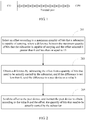
- An embodiment of the present invention provides a subcarrier information indicating method, including: Step 201: Select an offset according to a maximum quantity of bits that a subcarrier is capable of carrying, where a difference between the maximum quantity of bits that the subcarrier is capable of carrying and the selected offset is greater than 0 and less than or equal to 15.
- any one of values 2 to 16 may be selected as the offset.
- Step 203 Obtain a difference by subtracting the offset from a quantity of bits that need to be actually carried by the subcarrier, and if the difference is not less than 0, send the difference to a peer device as a value b.
- Step 205 Send the offset to the peer device, and instruct the peer device to obtain, according to the value b and the offset, the quantity of bits that need to be actually carried by the subcarrier.
- the subcarrier is a smallest unit carrier for transmitting information on a link connecting to the peer device.
- the selecting an offset includes: selecting, within a value range less than or equal to the maximum quantity of bits that the subcarrier is capable of carrying, a value as the offset, or obtaining the offset according to a preset mapping table between a maximum quantity of bits that each subcarrier is capable of carrying and an offset, so that the difference between the maximum quantity of bits that the subcarrier is capable of carrying and the selected offset is greater than 0 and less than or equal to 15.
- the offset may be 0 or another natural number.
- the method further includes: if the peer device also supports the obtained quantity of bits that need to be actually carried by the subcarrier, sending information in a data transmission phase according to the obtained quantity of bits that need to be actually carried by the subcarrier.
- the offset may be set in an O-PMD or R-PMD message and sent to the peer device.
- the method may be performed in a link initialization phase and/or in the data transmission phase.
- a larger quantity of bits can be sent by a subcarrier on a premise that a message format for exchanging table b information between a sender and a receiver keeps unchanged. This helps a sender to send data quickly and a receiver to read a message quickly, and can greatly improve a system processing rate.
- grouping all subcarriers in a transmission direction (an uplink direction or downlink direction) according to the maximum quantity of bits that the subcarrier is capable of carrying, so as to ensure that subcarriers in each group (group) can use a same offset.
- the offset of all the subcarriers in each group is the same, and referred to as a group offset.
- the sending the offset to the peer device includes: sending group information obtained by grouping all the subcarriers and the offset of each group to the peer device, to ensure that maximum quantities of bits that the subcarriers in each group are capable of carrying are the same.
- the group information may be represented by using a start subcarrier and an end subcarrier of each group.
- one offset may be set for each group in a configuration message.
- Two parameters need to be used: one parameter is an offset; the other parameter indicates a group corresponding to the offset and specifically, may be identified by using the start subcarrier and the end subcarrier of each group.
- the start subcarriers and the end subcarriers of groups can be arranged in order or according to another rule, and corresponding offsets of the groups are also arranged according to a corresponding rule.
- a string representing the two parameters is variable in length.
- a peer end when receiving a message configured with the two parameters, a peer end can obtain a quantity of bits that can be carried by subcarriers in each group and can normally process received information.
- a downstream max bit tone groups (Downstream Max Bit tone groups) field and a downstream max bit offset (Downstream Max Bit Offset) field are added to the R-PMD message, where in the downstream max bit tone groups field, a quantity of groups is represented by using one byte (8 bits), and the start and end subcarriers of each group are represented by using three bytes (24 bits).
- Downstream max bit offset may be converted to binary values (separately represented by two bits) according to the offsets of the three groups, and then be arranged in descending order as [00 10 11], where 11 indicates a value of offset 1 , 10 indicates a value of offset 2 , and 00 indicates a value of offset 3 .
- the local device sends R-PMD added with the downstream max bit tone groups field and the downstream max bit offset field to the peer end.
- the peer end can determine an offset corresponding to the subcarriers in each group.
- Processing in the uplink direction is similar to the foregoing method, except that a setting and processing object in the foregoing method is changed to an uplink subcarrier.
- the quantity of bytes used for representing the group quantity, the start and end subcarriers of each group, and the offset may be other values, and implementation of the present invention are not affected, as long as the foregoing parameters can be clearly represented, and can be normally identified by the sender and the receiver.
- offsets may be set between groups, and an offset may be separately set for subcarriers with a different carrying capability according to a group. Therefore, offsets are set more flexibly. For example, according to a relationship in table 2, when an offset of a group of subcarriers is k, it may indicate that a quantity of bits that need to be actually carried by the subcarriers is in a range of [0, k+1, k+2, ..., k+15]; when an offset of a group of subcarriers is k-1, it may indicate that a quantity of bits that need to be actually carried by the subcarriers is in a range of [0, k+1, k+2, ..., k+14].
- the subcarrier may be assigned to another group and be set to another offset, so as to ensure that the difference obtained by subtracting the offset from the quantity of bits that need to be actually carried by the subcarrier is not less than 0, and processing may be continued in a manner of steps 203 and 205.
- An embodiment of the present invention provides a subcarrier information processing method, where the method includes:
- the subcarrier is a smallest unit carrier for transmitting information on a link connecting to the peer device.
- the offset may be 0 or another natural number.
- the method further includes: determining whether the obtained quantity of bits that need to be actually carried by the subcarrier is supported; and if supported, sending information to the peer device in a data transmission phase according to the obtained quantity of bits that need to be actually carried by the subcarrier.
- the offset is sent by the peer device by using an O-PMD or R-PMD message.
- the receiving an offset sent by a peer device includes receiving subcarrier group information and an offset of each group that are sent by the peer device, where the offset of each group indicates an offset of all subcarriers in each group.
- All the subcarriers in each group are determined by identifying a start subcarrier and an end subcarrier of each group in the group information.
- the method may be performed in a link initialization phase and/or in the data transmission phase.
- An embodiment of the present invention further provides a network transmit device 400, where the network transmit device includes an offset obtaining unit 401 and a transmit unit 403.
- the offset obtaining unit 401 is configured to select an offset according to a maximum quantity of bits that a subcarrier is capable of carrying, where a difference between the maximum quantity of bits that the subcarrier is capable of carrying and the selected offset is greater than 0 and less than or equal to 15.
- the transmit unit 403 is configured to obtain a difference by subtracting the offset from a quantity of bits that need to be actually carried by the subcarrier, and if the difference is not less than 0, send the difference to a peer device as a value b, send the offset to the peer device, and instruct the peer device to obtain, according to the value b and the offset, the quantity of bits that need to be actually carried by the subcarrier.
- the subcarrier is a smallest unit carrier for transmitting information on a link between the network transmit device 400 and the peer device.
- the offset obtaining unit 401 selects, within a value range less than or equal to the maximum quantity of bits that the subcarrier is capable of carrying, a value as the offset, or obtains the offset according to a preset mapping table between a maximum quantity of bits that each subcarrier is capable of carrying and an offset.
- the offset may be 0 or another natural number.
- the transmit unit 403 is further configured to use, according to a requirement of the ITU-T G.993.2, four bits to represent the value b in a message field used for configuration of a table b, and send the value b to the peer device.
- the offset obtaining unit 401 is configured to group all subcarriers in a transmission direction according to the maximum quantity of bits that the subcarrier is capable of carrying, so as to ensure that subcarriers in each group can use a same offset.
- the offset of all the subcarriers in each group is the same, and referred to as a group offset.
- the transmit unit 403 sends group information obtained by grouping all the subcarriers and the offset of each group to the peer device.
- the network transmit device 400 is a CPE or a CO, and correspondingly, the transmit unit 403 is a transmitter of the CPE or the CO.
- An embodiment of the present invention provides a network receive device 500, where the network receive device 500 includes a receive unit 501 and an offset processing unit 503.
- the receive unit 501 is configured to receive an offset sent by a peer device; and receive a table b configuration message sent by the peer device, where the value b is a value that is represented by four bits and that indicates a quantity of bits that need to be carried by a subcarrier.
- the offset processing unit 503 is configured to, when it is identified that the value b in the message is not 0, use a sum of the value b and the offset as a quantity of bits that need to be actually carried by the subcarrier, and when it is identified that the value b is 0, use the value b as the quantity of bits that need to be actually carried by the subcarrier.
- the subcarrier is a smallest unit carrier for transmitting information on a link between the network receive device 500 and the peer device.
- the offset may be 0 or another natural number.
- the offset is sent by the peer device by using an O-PMD or R-PMD message.
- the receive unit 501 is further configured to receive subcarrier group information and an offset of each group that are sent by the peer device, where the offset of each group indicates an offset of all subcarriers in each group.
- the offset processing unit 503 is further configured to determine whether the obtained quantity of bits that need to be actually carried by the subcarrier is supported by the network receive device 500; and if supported, send information to the peer device in a data transmission phase according to the obtained quantity of bits that need to be actually carried by the subcarrier.
- the offset processing unit 503 determines all the subcarriers in each group by identifying a start subcarrier and an end subcarrier of each group in the group information.
- the network receive device 500 is a CPE or a CO, and correspondingly, the receive unit 501 is a receiver of the CPE or the CO.
- An embodiment of the present invention also provides a network system 600, including a network-side device 601 and a user-side device 603.
- the network-side device 601 is the network transmit device in the foregoing embodiments, and correspondingly, the user-side device 603 may be the network receive device in the foregoing embodiments.
- the network-side device 601 is the network receive device in the foregoing embodiments, and correspondingly, the user-side device 603 may be the network transmit device in the foregoing embodiments.
- FIG. 7 schematically illustrates an electrical general-purpose network component 700 that is applicable for implementing one or more embodiments of the components disclosed in the specification.
- the network component 700 includes a processor 702 (which may be referred to as a central processing unit or CPU).
- the processor 702 communicates with a storage device, including a second memory 704, a read only memory (ROM) 706, a random access memory (RAM) 708, an input/output (I/O) device 710, and a network connectivity device 712.
- the processor 702 may be implemented as one or more CPU chips, or may be implemented as a part of one or more application-specific integrated circuits.
- the second memory 704 is typically composed of one or more disk drives or disc drives and is configured to perform nonvolatile storage of data and, if the RAM 708 is insufficient to accommodate all of the work data, is used as an overflow data storage device.
- the second memory 704 may be configured to store programs that are loaded into the RAM 708 when being selected for execution, the ROM 706 is configured to store an instruction and/or data read during program execution, the ROM 706 is a nonvolatile storage device and typically has a relatively small memory capacity compared with a relatively large memory capacity of the second memory 704.
- the RAM 708 is configured to store volatile data and may store an instruction. Access to the ROM 706 and RAM 708 is generally faster than access to the second memory 704.
Landscapes
- Engineering & Computer Science (AREA)
- Signal Processing (AREA)
- Computer Networks & Wireless Communication (AREA)
- Mobile Radio Communication Systems (AREA)
- Data Exchanges In Wide-Area Networks (AREA)
Claims (11)
- Verfahren zum Anzeigen von Zwischenträgerinformationen, wobei das Verfahren umfasst:Auswählen eines Abstands einer maximalen Anzahl an Bits entsprechend, die ein Zwischenträger zu tragen in der Lage ist, wobei eine Differenz zwischen der maximalen Anzahl an Bits, die der Zwischenträger zu tragen in der Lage ist, und dem gewählten Abstand größer als 0 und geringer als oder gleich 15 ist (Schritt 201);Erhalten einer Differenz, die durch Abziehen des Abstands von einer Anzahl Bits erhalten wird, die durch den Zwischenträger tatsächlich zu tragen sind, und wenn die Differenz nicht weniger als 0 ist, Senden der Differenz in einer Meldung an eine Peer-Vorrichtung als Wert b, der durch vier Bits dargestellt wird (Schritt 203); undSenden des Abstands an die Peer-Vorrichtung und Anweisen der Peer-Vorrichtung, dem Wert b und dem Abstand entsprechend die Anzahl an Bits zu erhalten, die tatsächlich durch den Zwischenträger zu tragen sind (Schritt 205).
- Verfahren nach Anspruch 1, wobei das Auswählen eines Abstands umfasst: Auswählen innerhalb eines Wertebereichs von weniger als oder gleich der maximalen Anzahl an Bits, die der Zwischenträger tragen kann, eines Werts als Abstand, oder Erhalten des Abstands nach einer vorgegebenen Mapping-Tabelle zwischen einer maximalen Anzahl an Bits, die jeder Zwischenträger zu tragen in der Lage ist, und einem Abstand.
- Verfahren nach Anspruch 1 oder 2, wobei der Zwischenträger ein Träger einer kleinsten Einheit zum Übermitteln von Informationen über einen Link ist, der eine Verbindung mit der Peer-Vorrichtung herstellt.
- Verfahren nach einem der Ansprüche 1 bis 3, wobei das Senden des Abstands an die Peer-Vorrichtung umfasst: Gruppieren aller Zwischenträger in einer Übertragungsrichtung nach der maximalen Anzahl an Bits, die der Zwischenträger zu tragen in der Lage ist, um sicherzustellen, dass die Zwischenträger in jeder Gruppe einen selben Abstand nutzen können, und Senden von durch Gruppieren aller Zwischenträger erhaltenen Gruppeninformationen und des Abstands jeder Gruppe an die Peer-Vorrichtung.
- Verfahren zum Verarbeiten von Zwischenträgerinformationen, wobei das Verfahren umfasst:Empfangen eines Abstands, der durch eine Peer-Vorrichtung gesendet wird (Schritt 301);Empfangen einer Meldung, die einen Wert b umfasst und durch die Peer-Vorrichtung gesendet wird,wobei der Wert b ein Wert ist, der durch vier Bits dargestellt wird und eine Anzahl an Bits darstellt, die durch einen Zwischenträger zu tragen sind (Schritt 303); undwenn festgestellt wird, dass der Wert b in der Meldung nicht 0 ist, Verwenden einer Summe des Werts b und des Abstands als Anzahl an Bits, die tatsächlich durch den Zwischenträger zu tragen sind, und wenn festgestellt wird, dass der Wert b 0 ist, Verwenden des Werts b als Anzahl an Bits, die tatsächlich durch den Zwischenträger zu tragen sind (Schritt 305).
- Verfahren nach Anspruch 5, wobei das Verfahren ferner umfasst: Bestimmen, ob die erhaltene Anzahl an Bits, die tatsächlich durch den Zwischenträger zu tragen sind, unterstützt wird; und wenn sie unterstützt wird, Senden von Informationen an die Peer-Vorrichtung in einer Datenübertragungsphase der erhaltenen Anzahl an Bits entsprechend, die tatsächlich durch den Zwischenträger zu tragen sind.
- Verfahren nach Anspruch 5 oder 6, wobei der Zwischenträger ein Träger einer kleinsten Einheit zum Übermitteln von Informationen über einen Link ist, der eine Verbindung mit der Peer-Vorrichtung herstellt.
- Verfahren nach Anspruch 5, 6 oder 7, wobei der Abstand innerhalb einer O-PMD- oder R-PMD-Meldung auf Grundlage von ITU-T G.993.2 empfangen wird.
- Verfahren nach einem der Ansprüche 5 bis 8, wobei das Empfangen des Abstands, der durch die Peer-Vorrichtung gesendet wird, umfasst: Empfangen von Zwischenträgergruppeninformationen und eines Abstands jeder Gruppe, die durch die Peer-Vorrichtung gesendet werden, wobei der Abstand jeder Gruppe einen Abstand aller Zwischenträger jeder Gruppe darstellt.
- Netzwerkübertragungsvorrichtung (400), konfiguriert und vorgesehen, um eines der Verfahren nach Ansprüchen 1 bis 4 auszuführen.
- Netzwerkempfangsvorrichtung (500), konfiguriert und vorgesehen, um eines der Verfahren nach Ansprüchen 5 bis 9 auszuführen.
Priority Applications (1)
| Application Number | Priority Date | Filing Date | Title |
|---|---|---|---|
| EP18186802.7A EP3461093A1 (de) | 2014-12-31 | 2014-12-31 | Subträgerinformationsanzeigeverfahren, -vorrichtung und -system |
Applications Claiming Priority (1)
| Application Number | Priority Date | Filing Date | Title |
|---|---|---|---|
| PCT/CN2014/095883 WO2016106677A1 (zh) | 2014-12-31 | 2014-12-31 | 一种子载波信息指示方法、装置及系统 |
Related Child Applications (2)
| Application Number | Title | Priority Date | Filing Date |
|---|---|---|---|
| EP18186802.7A Division EP3461093A1 (de) | 2014-12-31 | 2014-12-31 | Subträgerinformationsanzeigeverfahren, -vorrichtung und -system |
| EP18186802.7A Division-Into EP3461093A1 (de) | 2014-12-31 | 2014-12-31 | Subträgerinformationsanzeigeverfahren, -vorrichtung und -system |
Publications (3)
| Publication Number | Publication Date |
|---|---|
| EP3240252A1 EP3240252A1 (de) | 2017-11-01 |
| EP3240252A4 EP3240252A4 (de) | 2018-01-03 |
| EP3240252B1 true EP3240252B1 (de) | 2018-10-03 |
Family
ID=56283951
Family Applications (2)
| Application Number | Title | Priority Date | Filing Date |
|---|---|---|---|
| EP14909486.4A Active EP3240252B1 (de) | 2014-12-31 | 2014-12-31 | Subträgerinformationsanzeigeverfahren, -vorrichtung und -system |
| EP18186802.7A Withdrawn EP3461093A1 (de) | 2014-12-31 | 2014-12-31 | Subträgerinformationsanzeigeverfahren, -vorrichtung und -system |
Family Applications After (1)
| Application Number | Title | Priority Date | Filing Date |
|---|---|---|---|
| EP18186802.7A Withdrawn EP3461093A1 (de) | 2014-12-31 | 2014-12-31 | Subträgerinformationsanzeigeverfahren, -vorrichtung und -system |
Country Status (3)
| Country | Link |
|---|---|
| EP (2) | EP3240252B1 (de) |
| CN (1) | CN105934920B (de) |
| WO (1) | WO2016106677A1 (de) |
Family Cites Families (5)
| Publication number | Priority date | Publication date | Assignee | Title |
|---|---|---|---|---|
| US6134273A (en) * | 1996-12-23 | 2000-10-17 | Texas Instruments Incorporated | Bit loading and rate adaptation on DMT DSL data transmission |
| US6829307B1 (en) * | 1999-02-24 | 2004-12-07 | The Board Of Trustees Of Leland Stanford Junior University | Express bit swapping in a multicarrier transmission system |
| CN101083553A (zh) * | 2006-05-30 | 2007-12-05 | 华为技术有限公司 | xDSL上下行共用频率动态频谱管理方法和装置 |
| CN101321145A (zh) * | 2007-06-07 | 2008-12-10 | 中兴通讯股份有限公司 | 一种在线更新dsl参数的方法 |
| US8879647B2 (en) * | 2012-04-26 | 2014-11-04 | Alcatel Lucent | Methods of allocating resources in a system and systems implementing the same |
-
2014
- 2014-12-31 EP EP14909486.4A patent/EP3240252B1/de active Active
- 2014-12-31 CN CN201480035410.8A patent/CN105934920B/zh active Active
- 2014-12-31 EP EP18186802.7A patent/EP3461093A1/de not_active Withdrawn
- 2014-12-31 WO PCT/CN2014/095883 patent/WO2016106677A1/zh not_active Ceased
Non-Patent Citations (1)
| Title |
|---|
| None * |
Also Published As
| Publication number | Publication date |
|---|---|
| EP3461093A1 (de) | 2019-03-27 |
| CN105934920B (zh) | 2019-04-05 |
| WO2016106677A1 (zh) | 2016-07-07 |
| EP3240252A1 (de) | 2017-11-01 |
| CN105934920A (zh) | 2016-09-07 |
| EP3240252A4 (de) | 2018-01-03 |
Similar Documents
| Publication | Publication Date | Title |
|---|---|---|
| US11018829B2 (en) | System and method for determining a pilot signal | |
| KR102179296B1 (ko) | 디바이스간 통신을 위해 송신 전력을 관리하기 위한 방법 및 장치 | |
| JP7254229B2 (ja) | Dciにおける情報ドメイン値を特定する方法及び装置 | |
| KR20060042209A (ko) | 채널 조건 모델을 사용하여 비트로딩을 하는 디지털 가입자라인 모뎀 | |
| CN112398604B (zh) | 信息确定方法和装置 | |
| CN103634086B (zh) | 调整上下行时间分配的方法、系统、局端设备及cpe | |
| EP4472275A1 (de) | Verfahren zur meldung von kanalstatusinformationen, verfahren zum empfangen von kanalstatusinformationen, endgerät, basisstation und speichermedium | |
| EP3684023A1 (de) | Verfahren zum konfigurieren von planungsanfragen, netzwerkvorrichtung und endgerät | |
| EP3582405A1 (de) | Verfahren und vorrichtung zur bestimmung der vorcodierungsgranularität | |
| US11025362B2 (en) | Dynamic time adjustment method, apparatus, and system | |
| EP3700141B1 (de) | Pilotinformationübertragungsverfahren und zugehörige vorrichtung | |
| KR20230049707A (ko) | 물리 업링크 제어 채널 전송 방법, 수신 방법 및 통신 장치 | |
| US11166304B2 (en) | Downlink control channel configuration method, network device, and terminal | |
| CN112449413B (zh) | 功率指示方法、确定方法、装置、网络侧设备及终端 | |
| CN112236964A (zh) | NR TDD无线电帧配置和CLI灵敏度的gNB Xn间信令 | |
| CN111193969B (zh) | 一种基于dpu的数据通信与通信管理方法及dpu | |
| EP3240252B1 (de) | Subträgerinformationsanzeigeverfahren, -vorrichtung und -system | |
| CN101674165A (zh) | 多载波通信系统中信号误差的反馈方法、设备及系统 | |
| EP3200354B1 (de) | Nebensprechunterdrückungsverfahren, -vorrichtung und -system | |
| WO2014176791A1 (zh) | 多载波分复用系统的方法和装置 | |
| CN104025528B (zh) | 一种在线重配置的执行方法、装置和系统 | |
| EP1858287B1 (de) | Ein adaptives Aktivierungsverfahren anhand einer multimoden XDSL-Linien-Karte und das dabei verwendete System | |
| EP3720166A1 (de) | Verfahren und vorrichtung zur verarbeitung eines initialisierungssignals | |
| EP3605895A1 (de) | Vorcodierungsverarbeitungsverfahren und -vorrichtung und speichermedium | |
| US20250142410A1 (en) | Reconfiguration of modem devices to limit channel bonding capacity |
Legal Events
| Date | Code | Title | Description |
|---|---|---|---|
| STAA | Information on the status of an ep patent application or granted ep patent |
Free format text: STATUS: THE INTERNATIONAL PUBLICATION HAS BEEN MADE |
|
| PUAI | Public reference made under article 153(3) epc to a published international application that has entered the european phase |
Free format text: ORIGINAL CODE: 0009012 |
|
| STAA | Information on the status of an ep patent application or granted ep patent |
Free format text: STATUS: REQUEST FOR EXAMINATION WAS MADE |
|
| 17P | Request for examination filed |
Effective date: 20170728 |
|
| AK | Designated contracting states |
Kind code of ref document: A1 Designated state(s): AL AT BE BG CH CY CZ DE DK EE ES FI FR GB GR HR HU IE IS IT LI LT LU LV MC MK MT NL NO PL PT RO RS SE SI SK SM TR |
|
| AX | Request for extension of the european patent |
Extension state: BA ME |
|
| A4 | Supplementary search report drawn up and despatched |
Effective date: 20171206 |
|
| RIC1 | Information provided on ipc code assigned before grant |
Ipc: H04L 5/00 20060101ALI20171130BHEP Ipc: H04B 3/02 20060101ALI20171130BHEP Ipc: H04L 27/26 20060101AFI20171130BHEP |
|
| DAX | Request for extension of the european patent (deleted) | ||
| GRAP | Despatch of communication of intention to grant a patent |
Free format text: ORIGINAL CODE: EPIDOSNIGR1 |
|
| STAA | Information on the status of an ep patent application or granted ep patent |
Free format text: STATUS: GRANT OF PATENT IS INTENDED |
|
| RIC1 | Information provided on ipc code assigned before grant |
Ipc: H04B 3/02 20060101ALI20180406BHEP Ipc: H04L 27/26 20060101AFI20180406BHEP Ipc: H04L 5/00 20060101ALI20180406BHEP |
|
| INTG | Intention to grant announced |
Effective date: 20180425 |
|
| GRAS | Grant fee paid |
Free format text: ORIGINAL CODE: EPIDOSNIGR3 |
|
| GRAA | (expected) grant |
Free format text: ORIGINAL CODE: 0009210 |
|
| STAA | Information on the status of an ep patent application or granted ep patent |
Free format text: STATUS: THE PATENT HAS BEEN GRANTED |
|
| AK | Designated contracting states |
Kind code of ref document: B1 Designated state(s): AL AT BE BG CH CY CZ DE DK EE ES FI FR GB GR HR HU IE IS IT LI LT LU LV MC MK MT NL NO PL PT RO RS SE SI SK SM TR |
|
| REG | Reference to a national code |
Ref country code: GB Ref legal event code: FG4D |
|
| REG | Reference to a national code |
Ref country code: CH Ref legal event code: EP Ref country code: AT Ref legal event code: REF Ref document number: 1049868 Country of ref document: AT Kind code of ref document: T Effective date: 20181015 |
|
| REG | Reference to a national code |
Ref country code: IE Ref legal event code: FG4D Ref country code: DE Ref legal event code: R096 Ref document number: 602014033611 Country of ref document: DE |
|
| REG | Reference to a national code |
Ref country code: NL Ref legal event code: MP Effective date: 20181003 |
|
| REG | Reference to a national code |
Ref country code: LT Ref legal event code: MG4D |
|
| REG | Reference to a national code |
Ref country code: AT Ref legal event code: MK05 Ref document number: 1049868 Country of ref document: AT Kind code of ref document: T Effective date: 20181003 |
|
| PG25 | Lapsed in a contracting state [announced via postgrant information from national office to epo] |
Ref country code: NL Free format text: LAPSE BECAUSE OF FAILURE TO SUBMIT A TRANSLATION OF THE DESCRIPTION OR TO PAY THE FEE WITHIN THE PRESCRIBED TIME-LIMIT Effective date: 20181003 |
|
| PG25 | Lapsed in a contracting state [announced via postgrant information from national office to epo] |
Ref country code: IS Free format text: LAPSE BECAUSE OF FAILURE TO SUBMIT A TRANSLATION OF THE DESCRIPTION OR TO PAY THE FEE WITHIN THE PRESCRIBED TIME-LIMIT Effective date: 20190203 Ref country code: FI Free format text: LAPSE BECAUSE OF FAILURE TO SUBMIT A TRANSLATION OF THE DESCRIPTION OR TO PAY THE FEE WITHIN THE PRESCRIBED TIME-LIMIT Effective date: 20181003 Ref country code: CZ Free format text: LAPSE BECAUSE OF FAILURE TO SUBMIT A TRANSLATION OF THE DESCRIPTION OR TO PAY THE FEE WITHIN THE PRESCRIBED TIME-LIMIT Effective date: 20181003 Ref country code: AT Free format text: LAPSE BECAUSE OF FAILURE TO SUBMIT A TRANSLATION OF THE DESCRIPTION OR TO PAY THE FEE WITHIN THE PRESCRIBED TIME-LIMIT Effective date: 20181003 Ref country code: LV Free format text: LAPSE BECAUSE OF FAILURE TO SUBMIT A TRANSLATION OF THE DESCRIPTION OR TO PAY THE FEE WITHIN THE PRESCRIBED TIME-LIMIT Effective date: 20181003 Ref country code: LT Free format text: LAPSE BECAUSE OF FAILURE TO SUBMIT A TRANSLATION OF THE DESCRIPTION OR TO PAY THE FEE WITHIN THE PRESCRIBED TIME-LIMIT Effective date: 20181003 Ref country code: NO Free format text: LAPSE BECAUSE OF FAILURE TO SUBMIT A TRANSLATION OF THE DESCRIPTION OR TO PAY THE FEE WITHIN THE PRESCRIBED TIME-LIMIT Effective date: 20190103 Ref country code: BG Free format text: LAPSE BECAUSE OF FAILURE TO SUBMIT A TRANSLATION OF THE DESCRIPTION OR TO PAY THE FEE WITHIN THE PRESCRIBED TIME-LIMIT Effective date: 20190103 Ref country code: ES Free format text: LAPSE BECAUSE OF FAILURE TO SUBMIT A TRANSLATION OF THE DESCRIPTION OR TO PAY THE FEE WITHIN THE PRESCRIBED TIME-LIMIT Effective date: 20181003 Ref country code: PL Free format text: LAPSE BECAUSE OF FAILURE TO SUBMIT A TRANSLATION OF THE DESCRIPTION OR TO PAY THE FEE WITHIN THE PRESCRIBED TIME-LIMIT Effective date: 20181003 Ref country code: HR Free format text: LAPSE BECAUSE OF FAILURE TO SUBMIT A TRANSLATION OF THE DESCRIPTION OR TO PAY THE FEE WITHIN THE PRESCRIBED TIME-LIMIT Effective date: 20181003 |
|
| PG25 | Lapsed in a contracting state [announced via postgrant information from national office to epo] |
Ref country code: AL Free format text: LAPSE BECAUSE OF FAILURE TO SUBMIT A TRANSLATION OF THE DESCRIPTION OR TO PAY THE FEE WITHIN THE PRESCRIBED TIME-LIMIT Effective date: 20181003 Ref country code: PT Free format text: LAPSE BECAUSE OF FAILURE TO SUBMIT A TRANSLATION OF THE DESCRIPTION OR TO PAY THE FEE WITHIN THE PRESCRIBED TIME-LIMIT Effective date: 20190203 Ref country code: SE Free format text: LAPSE BECAUSE OF FAILURE TO SUBMIT A TRANSLATION OF THE DESCRIPTION OR TO PAY THE FEE WITHIN THE PRESCRIBED TIME-LIMIT Effective date: 20181003 Ref country code: GR Free format text: LAPSE BECAUSE OF FAILURE TO SUBMIT A TRANSLATION OF THE DESCRIPTION OR TO PAY THE FEE WITHIN THE PRESCRIBED TIME-LIMIT Effective date: 20190104 Ref country code: RS Free format text: LAPSE BECAUSE OF FAILURE TO SUBMIT A TRANSLATION OF THE DESCRIPTION OR TO PAY THE FEE WITHIN THE PRESCRIBED TIME-LIMIT Effective date: 20181003 |
|
| REG | Reference to a national code |
Ref country code: DE Ref legal event code: R097 Ref document number: 602014033611 Country of ref document: DE |
|
| PG25 | Lapsed in a contracting state [announced via postgrant information from national office to epo] |
Ref country code: DK Free format text: LAPSE BECAUSE OF FAILURE TO SUBMIT A TRANSLATION OF THE DESCRIPTION OR TO PAY THE FEE WITHIN THE PRESCRIBED TIME-LIMIT Effective date: 20181003 |
|
| REG | Reference to a national code |
Ref country code: CH Ref legal event code: PL |
|
| PLBE | No opposition filed within time limit |
Free format text: ORIGINAL CODE: 0009261 |
|
| STAA | Information on the status of an ep patent application or granted ep patent |
Free format text: STATUS: NO OPPOSITION FILED WITHIN TIME LIMIT |
|
| PG25 | Lapsed in a contracting state [announced via postgrant information from national office to epo] |
Ref country code: RO Free format text: LAPSE BECAUSE OF FAILURE TO SUBMIT A TRANSLATION OF THE DESCRIPTION OR TO PAY THE FEE WITHIN THE PRESCRIBED TIME-LIMIT Effective date: 20181003 Ref country code: SM Free format text: LAPSE BECAUSE OF FAILURE TO SUBMIT A TRANSLATION OF THE DESCRIPTION OR TO PAY THE FEE WITHIN THE PRESCRIBED TIME-LIMIT Effective date: 20181003 Ref country code: EE Free format text: LAPSE BECAUSE OF FAILURE TO SUBMIT A TRANSLATION OF THE DESCRIPTION OR TO PAY THE FEE WITHIN THE PRESCRIBED TIME-LIMIT Effective date: 20181003 Ref country code: MC Free format text: LAPSE BECAUSE OF FAILURE TO SUBMIT A TRANSLATION OF THE DESCRIPTION OR TO PAY THE FEE WITHIN THE PRESCRIBED TIME-LIMIT Effective date: 20181003 Ref country code: SK Free format text: LAPSE BECAUSE OF FAILURE TO SUBMIT A TRANSLATION OF THE DESCRIPTION OR TO PAY THE FEE WITHIN THE PRESCRIBED TIME-LIMIT Effective date: 20181003 Ref country code: LU Free format text: LAPSE BECAUSE OF NON-PAYMENT OF DUE FEES Effective date: 20181231 |
|
| 26N | No opposition filed |
Effective date: 20190704 |
|
| GBPC | Gb: european patent ceased through non-payment of renewal fee |
Effective date: 20190103 |
|
| REG | Reference to a national code |
Ref country code: BE Ref legal event code: MM Effective date: 20181231 Ref country code: IE Ref legal event code: MM4A |
|
| PG25 | Lapsed in a contracting state [announced via postgrant information from national office to epo] |
Ref country code: IE Free format text: LAPSE BECAUSE OF NON-PAYMENT OF DUE FEES Effective date: 20181231 Ref country code: FR Free format text: LAPSE BECAUSE OF NON-PAYMENT OF DUE FEES Effective date: 20181231 Ref country code: SI Free format text: LAPSE BECAUSE OF FAILURE TO SUBMIT A TRANSLATION OF THE DESCRIPTION OR TO PAY THE FEE WITHIN THE PRESCRIBED TIME-LIMIT Effective date: 20181003 |
|
| PG25 | Lapsed in a contracting state [announced via postgrant information from national office to epo] |
Ref country code: BE Free format text: LAPSE BECAUSE OF NON-PAYMENT OF DUE FEES Effective date: 20181231 |
|
| PG25 | Lapsed in a contracting state [announced via postgrant information from national office to epo] |
Ref country code: GB Free format text: LAPSE BECAUSE OF NON-PAYMENT OF DUE FEES Effective date: 20190103 Ref country code: CH Free format text: LAPSE BECAUSE OF NON-PAYMENT OF DUE FEES Effective date: 20181231 Ref country code: LI Free format text: LAPSE BECAUSE OF NON-PAYMENT OF DUE FEES Effective date: 20181231 |
|
| PG25 | Lapsed in a contracting state [announced via postgrant information from national office to epo] |
Ref country code: MT Free format text: LAPSE BECAUSE OF NON-PAYMENT OF DUE FEES Effective date: 20181231 |
|
| PG25 | Lapsed in a contracting state [announced via postgrant information from national office to epo] |
Ref country code: TR Free format text: LAPSE BECAUSE OF FAILURE TO SUBMIT A TRANSLATION OF THE DESCRIPTION OR TO PAY THE FEE WITHIN THE PRESCRIBED TIME-LIMIT Effective date: 20181003 |
|
| PG25 | Lapsed in a contracting state [announced via postgrant information from national office to epo] |
Ref country code: MK Free format text: LAPSE BECAUSE OF NON-PAYMENT OF DUE FEES Effective date: 20181003 Ref country code: HU Free format text: LAPSE BECAUSE OF FAILURE TO SUBMIT A TRANSLATION OF THE DESCRIPTION OR TO PAY THE FEE WITHIN THE PRESCRIBED TIME-LIMIT; INVALID AB INITIO Effective date: 20141231 Ref country code: CY Free format text: LAPSE BECAUSE OF FAILURE TO SUBMIT A TRANSLATION OF THE DESCRIPTION OR TO PAY THE FEE WITHIN THE PRESCRIBED TIME-LIMIT Effective date: 20181003 |
|
| PGFP | Annual fee paid to national office [announced via postgrant information from national office to epo] |
Ref country code: DE Payment date: 20241105 Year of fee payment: 11 |
|
| PGFP | Annual fee paid to national office [announced via postgrant information from national office to epo] |
Ref country code: IT Payment date: 20241112 Year of fee payment: 11 |