EP3240146B1 - Electric rotating machine and manufacturing method for electric rotating machine - Google Patents
Electric rotating machine and manufacturing method for electric rotating machine Download PDFInfo
- Publication number
- EP3240146B1 EP3240146B1 EP17167714.9A EP17167714A EP3240146B1 EP 3240146 B1 EP3240146 B1 EP 3240146B1 EP 17167714 A EP17167714 A EP 17167714A EP 3240146 B1 EP3240146 B1 EP 3240146B1
- Authority
- EP
- European Patent Office
- Prior art keywords
- center hole
- conductors
- center
- shaft
- rotor
- Prior art date
- Legal status (The legal status is an assumption and is not a legal conclusion. Google has not performed a legal analysis and makes no representation as to the accuracy of the status listed.)
- Active
Links
- 238000004519 manufacturing process Methods 0.000 title claims description 6
- 239000004020 conductor Substances 0.000 claims description 238
- 230000002093 peripheral effect Effects 0.000 claims description 49
- 239000000112 cooling gas Substances 0.000 claims description 9
- 239000007789 gas Substances 0.000 claims description 7
- 230000004323 axial length Effects 0.000 description 4
- 230000000694 effects Effects 0.000 description 4
- 125000006850 spacer group Chemical group 0.000 description 4
- 230000005540 biological transmission Effects 0.000 description 3
- 230000008878 coupling Effects 0.000 description 3
- 238000010168 coupling process Methods 0.000 description 3
- 238000005859 coupling reaction Methods 0.000 description 3
- 239000000463 material Substances 0.000 description 3
- 230000007423 decrease Effects 0.000 description 2
- 238000010586 diagram Methods 0.000 description 2
- 238000009413 insulation Methods 0.000 description 2
- RYGMFSIKBFXOCR-UHFFFAOYSA-N Copper Chemical compound [Cu] RYGMFSIKBFXOCR-UHFFFAOYSA-N 0.000 description 1
- 229910000639 Spring steel Inorganic materials 0.000 description 1
- 230000000712 assembly Effects 0.000 description 1
- 238000000429 assembly Methods 0.000 description 1
- 229910052802 copper Inorganic materials 0.000 description 1
- 239000010949 copper Substances 0.000 description 1
- 239000012212 insulator Substances 0.000 description 1
- 230000013011 mating Effects 0.000 description 1
- 238000000034 method Methods 0.000 description 1
- 230000000149 penetrating effect Effects 0.000 description 1
- 238000010248 power generation Methods 0.000 description 1
- 238000007789 sealing Methods 0.000 description 1
- 238000010008 shearing Methods 0.000 description 1
- 238000004804 winding Methods 0.000 description 1
Images


Classifications
-
- H—ELECTRICITY
- H02—GENERATION; CONVERSION OR DISTRIBUTION OF ELECTRIC POWER
- H02K—DYNAMO-ELECTRIC MACHINES
- H02K3/00—Details of windings
- H02K3/04—Windings characterised by the conductor shape, form or construction, e.g. with bar conductors
- H02K3/28—Layout of windings or of connections between windings
-
- H—ELECTRICITY
- H02—GENERATION; CONVERSION OR DISTRIBUTION OF ELECTRIC POWER
- H02K—DYNAMO-ELECTRIC MACHINES
- H02K9/00—Arrangements for cooling or ventilating
- H02K9/08—Arrangements for cooling or ventilating by gaseous cooling medium circulating wholly within the machine casing
-
- H—ELECTRICITY
- H02—GENERATION; CONVERSION OR DISTRIBUTION OF ELECTRIC POWER
- H02K—DYNAMO-ELECTRIC MACHINES
- H02K3/00—Details of windings
- H02K3/46—Fastening of windings on the stator or rotor structure
- H02K3/50—Fastening of winding heads, equalising connectors, or connections thereto
- H02K3/51—Fastening of winding heads, equalising connectors, or connections thereto applicable to rotors only
-
- H—ELECTRICITY
- H02—GENERATION; CONVERSION OR DISTRIBUTION OF ELECTRIC POWER
- H02K—DYNAMO-ELECTRIC MACHINES
- H02K1/00—Details of the magnetic circuit
- H02K1/06—Details of the magnetic circuit characterised by the shape, form or construction
- H02K1/22—Rotating parts of the magnetic circuit
- H02K1/26—Rotor cores with slots for windings
-
- H—ELECTRICITY
- H02—GENERATION; CONVERSION OR DISTRIBUTION OF ELECTRIC POWER
- H02K—DYNAMO-ELECTRIC MACHINES
- H02K1/00—Details of the magnetic circuit
- H02K1/06—Details of the magnetic circuit characterised by the shape, form or construction
- H02K1/22—Rotating parts of the magnetic circuit
- H02K1/32—Rotating parts of the magnetic circuit with channels or ducts for flow of cooling medium
-
- H—ELECTRICITY
- H02—GENERATION; CONVERSION OR DISTRIBUTION OF ELECTRIC POWER
- H02K—DYNAMO-ELECTRIC MACHINES
- H02K13/00—Structural associations of current collectors with motors or generators, e.g. brush mounting plates or connections to windings; Disposition of current collectors in motors or generators; Arrangements for improving commutation
- H02K13/003—Structural associations of slip-rings
-
- H—ELECTRICITY
- H02—GENERATION; CONVERSION OR DISTRIBUTION OF ELECTRIC POWER
- H02K—DYNAMO-ELECTRIC MACHINES
- H02K13/00—Structural associations of current collectors with motors or generators, e.g. brush mounting plates or connections to windings; Disposition of current collectors in motors or generators; Arrangements for improving commutation
- H02K13/02—Connections between slip-rings and windings
-
- H—ELECTRICITY
- H02—GENERATION; CONVERSION OR DISTRIBUTION OF ELECTRIC POWER
- H02K—DYNAMO-ELECTRIC MACHINES
- H02K15/00—Methods or apparatus specially adapted for manufacturing, assembling, maintaining or repairing of dynamo-electric machines
- H02K15/0056—Manufacturing winding connections
-
- H—ELECTRICITY
- H02—GENERATION; CONVERSION OR DISTRIBUTION OF ELECTRIC POWER
- H02K—DYNAMO-ELECTRIC MACHINES
- H02K15/00—Methods or apparatus specially adapted for manufacturing, assembling, maintaining or repairing of dynamo-electric machines
- H02K15/02—Methods or apparatus specially adapted for manufacturing, assembling, maintaining or repairing of dynamo-electric machines of stator or rotor bodies
-
- H—ELECTRICITY
- H02—GENERATION; CONVERSION OR DISTRIBUTION OF ELECTRIC POWER
- H02K—DYNAMO-ELECTRIC MACHINES
- H02K3/00—Details of windings
- H02K3/04—Windings characterised by the conductor shape, form or construction, e.g. with bar conductors
- H02K3/24—Windings characterised by the conductor shape, form or construction, e.g. with bar conductors with channels or ducts for cooling medium between the conductors
-
- H—ELECTRICITY
- H02—GENERATION; CONVERSION OR DISTRIBUTION OF ELECTRIC POWER
- H02K—DYNAMO-ELECTRIC MACHINES
- H02K3/00—Details of windings
- H02K3/32—Windings characterised by the shape, form or construction of the insulation
- H02K3/34—Windings characterised by the shape, form or construction of the insulation between conductors or between conductor and core, e.g. slot insulation
-
- H—ELECTRICITY
- H02—GENERATION; CONVERSION OR DISTRIBUTION OF ELECTRIC POWER
- H02K—DYNAMO-ELECTRIC MACHINES
- H02K9/00—Arrangements for cooling or ventilating
- H02K9/10—Arrangements for cooling or ventilating by gaseous cooling medium flowing in closed circuit, a part of which is external to the machine casing
Definitions
- Embodiments described herein relate generally to an electric rotating machine and a manufacturing method for an electric rotating machine.
- a driving machine is connected to one end of a rotor of an electric rotating machine.
- external power is supplied to a collector ring installed at the other end of the rotor.
- the power is supplied to a rotor coil through studs inserted into holes formed in a shaft in a radial direction and center hole conductors inserted into a center hole in the shaft.
- An increased output from the electric rotating machine also increases power supplied to the rotor coil, so that a current flowing through the rotor coil also increases.
- each part of the current circuit can be settled increasing sectional area.
- a sufficient sectional area can be provided according to the increased current by increasing the diameter of each of the studs or the number of the studs to increase the sectional area of the current circuit.
- the shaft needs to have shear strength sufficient to resist a transmission torque applied to the rotor, so the holes which extend from the center hole in the shaft to an outer periphery of the shaft for studs are inhibited from being formed in the shaft depending on the magnitude of the torque.
- the diameter of the shaft is inhibited from being increased to increase the shearing strength at the end of the rotor at which the collector ring with a peripheral speed limit is provided.
- conductors are arranged in the radial direction of the rotor and bolted and thus electrically connected to the center hole conductors.
- JP 2013017307 A discloses a gas-cooled electric rotating machine which has collector rings installed around an outer periphery of a rotating shaft and a pair of conductors inserted into a center hole formed in the shaft in a direction along a rotation center thereof so as to be insulated from the shaft and from each other.
- the collector rings are electrically connected to the conductors by means of connecting terminals respectively penetrating the shaft in a radial direction and reaching to the respective conductor in the center hole.
- EP 0645874 A1 discloses an electrical machine with collector rings installed around an outer periphery of a protruding stump of a rotating machine shaft and a pair of conductors inserted into a center hole formed in the machine shaft and the stump in a direction along a rotation center.
- the protruding stump is releasably connected to the machine shaft in an axial direction by means of a coupling.
- JP H0350965 U discloses another example of an electrical connection between collector rings installed around an outer periphery of a shaft of a rotor and an internal winding of an electrical motor.
- the electrical connecting wire extends not through a center hole of the shaft.
- GB 879165 A discloses improvements in or relating to gas-tight sealing assemblies for dynamo-electric machines, wherein connector bars inserted into a center hole of a shaft are connected to a pair of collector rings installed around an outer periphery of the shaft in that cylindrical extensions of terminal ends of the connector bars are provided with threaded axial cylindrical holes and a connector lead is secured to the respective connector bar by means of a bolt threaded into the axial hole.
- the object of the present invention is to provide an electric rotating machine and a manufacturing method for an electric rotating machine in which center hole conductors configured to supply power to a rotor coil can be electrically connected to conductors located outside the center hole with a sufficient contact area provided between the center hole conductors and the conductors outside the center hole.
- a gas cooled electric rotating machine with the features of claim 1 in which a cooling gas is flowed through into a rotor and a stator.
- the rotor includes a shaft having a center hole formed along a center of rotation of the rotor and a hole for studs formed at a machine interior side of the center hole so as to extend in a radial direction from the center hole to an outer peripheral surface of the rotor to allow the center hole and the outer peripheral surface to communicate with each other.
- the rotor includes a pair of center hole conductors inserted into the center hole along the center of rotation while being electrically insulated from the shaft and from each other, the center hole conductors including respective protruding parts protruding toward an end of the shaft.
- the rotor includes a pair of end conductors provided at the end of the shaft so as to be each electrically insulated from the shaft, the end conductors being electrically connected to side surfaces of the protruding parts of the pair of center hole conductors, the side surfaces serving as electric connection surfaces.
- the invention also provides a manufacturing method for an electric rotating machine with the features of claim 4.
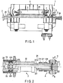
- FIG. 1 is a diagram depicting an example of an electric rotating machine in the first embodiment.
- FIG. 2 , FIG. 3 , and FIG. 4 are sectional views depicting an example of an end of a rotor of the electric rotating machine in the first embodiment.
- FIG. 3 is an enlarged view of a portion A depicted in FIG. 2 .
- FIG. 4 is a sectional view taken along line B-B in FIG. 2 .
- FIG. 5 is a perspective view of an end conductor depicted in FIG. 2 .
- FIG. 6 is a perspective view of a center hole conductor depicted in FIG. 2 .
- An electric rotating machine 1 depicted in FIG. 1 is a gas-cooled electric rotating machine in which a cooling gas is flowed through into a rotor 2 and a stator 3.
- the stator 3 arranged on an outer periphery of the rotor 2 is attached to an inner surface of a stator frame (frame) 4.
- An end (to which a power feeding apparatus is connected) 2A of the rotor 2 extends through the stator frame 4 and is supported by a bearing 5 to seal, at a position closer to the center of the stator than the bearing 5, the cooling gas in the stator frame 4 with an oil seal 6.
- the rotor 2 of the electric rotating machine 1 includes as a main component a shaft 20 with a center hole 201 formed in a central part thereof.
- the rotor 2 further includes as field circuit components the rotor coil 7, center hole conductors 211, 221, end conductors 212, 222, and radial studs 213, 223.
- the center hole conductor 211, the end conductor 212, and the radial stud 213 are positioned 180° away from the center hole conductor 221, the end conductor 222, and the radial stud 223 symmetrically with respect to a center of rotation L.
- the rotor 2 has collector rings 214, 224.
- the collector rings 214, 224 are installed around an outer periphery of the shaft 20 extending outward of the stator frame 4.
- the collector rings 214, 224 are installed in juxtaposition in an axial direction of the shaft 20 so as to be insulated from the shaft 20 using an insulating member.
- Outer peripheral surfaces of the collector rings 214, 224 are electrically connected together by slidable movement with a power feeding brush.
- the insulation described below is electric insulation.
- the center hole 201 and holes 202 for studs located at a machine interior side are formed at the end 2A.
- the center hole 201 is formed along the center of rotation L.
- the holes 202 for studs are located near the rotor coil 7 and extend in a radial direction so as to allow the center hole 201 to communicate with an outer peripheral surface of the shaft 20.
- the holes 202 for studs are formed line-symmetrically with respect to the center of rotation L, that is, 180° away from each other in a circumferential direction.
- the pair of center hole conductors 211, 221 is inserted into the center hole 201 along the center of rotation L so as to be electrically insulated from the shaft 20 and from each other.
- An insulating board 262 is interposed between the center hole conductors 211, 221 to electrically insulate the center hole conductors 211, 221 from each other.
- An insulating pipe 261 for the center hole conductors is installed between an inner periphery of the center hole 201 (which faces the center hole conductors 211, 221) and the center hole conductors 211, 221.
- An insulating block 263 is interposed between the end 2A and the pair of end conductors 212, 222.
- An insulating board 264 is interposed between the end conductor 212 and an end surface of the shaft 20 so as to electrically insulate the end conductor 212 from the end surface.
- the insulating board 264 is also interposed between the end conductor 222 and the shaft 20.
- Radial studs 213, 223 are inserted into the holes 202 for studs, located 180° away from each other and insulated from the shaft 20.
- the radial stud 213 electrically connects a lead conductor 7A of the rotor coil 7 and the center hole conductor 211 together.
- the radial stud 223 electrically connects a lead conductor 7B of the rotor coil 7 and the center hole conductor 221 together.
- the radial stud 213 is connected to an end of the rotor coil 7 via the lead conductor 7A.
- the rotor coil 7 is prepared as one of bend parts not depicted in the drawings.
- the radial stud 223 is connected to the end of the rotor coil 7 via the lead conductor 7B.
- the lead conductors 7A, 7B are housed in a slot along the center of rotation L.
- the slot is formed in the outer peripheral surface of the shaft 20.
- the end conductors 212, 222 are electrically connected to the collector rings 214, 224 on a one-to-one basis.
- the collector rings 214, 224 are installed on the outer periphery of the end of the shaft 20 via an insulating pipe 271 for the collector rings.
- the collector rings 214, 224 are electrically connected together by slidable movement with the power feeding brush.
- the power feeding brush is attached to a power feeding apparatus installed outside of the collector rings 214, 224.
- an insulating plug 265 is housed which has through-holes 265A, 265B through which ends of center hole conductor 211, 221 extend.
- the insulating plug 265 is located at center hole conductor ends 211A, 221A to electrically insulate the shaft 20 from the center hole conductors 211, 221 and to seal the cooling gas.
- a gasket 281 is fitted into a groove in an outer peripheral surface of an end of the center hole conductor 211 (more specifically, a part of the center hole conductor 211 located at the machine interior side with respect to the center hole conductor end 211A, which serves as a part of the center hole conductor 211 protruding toward the end of the shaft 20) so as to extend in the axial direction; the groove is formed so as to face an inner periphery of the through-hole 265A in the insulating plug 265. Consequently, a gas seal is formed between the outer peripheral surface of the end of the center hole conductor 211 and the insulating plug 265.
- a gasket 282 is fitted into a groove in an outer peripheral surface of an end of the center hole conductor 221 (more specifically, a part of the center hole conductor 221 located at the machine interior side with respect to the center hole conductor end 221A, which serves as a part of the center hole conductor 221 protruding toward the end of the shaft 20) so as to extend in the axial direction; the groove is formed so as to face an inner periphery of the through-hole 265B in the insulating plug 265. Consequently, a gas seal is formed between the above-described outer peripheral surface and the insulating plug 265.
- a gasket 283 is fitted into a groove formed in an outer periphery of the insulating plug 265 such that the gasket 283 extends in the axial direction.
- the gasket 283 is arranged between the insulating plug 265 and the center hole 201 so as to extend in the axial direction. Consequently, a gas seal is formed between the insulating plug 265 and an inner peripheral surface of the center hole 201.
- the gaskets 281, 282, 283 are arranged in the axial direction between each of the center hole conductor ends 211A, 221A and the insulating plug 265 and between the insulating plug 265 and the center hole 201 in the shaft 20 and to seal the cooling gas.
- the center hole conductor ends 211A, 221A which serve as protruding parts, are cylindrically formed.
- a hole is formed in the end conductor 212 so that the center hole conductor end 211A is fitted into the hole.
- an electric connection surface an inner peripheral surface of the above-described hole is connected to the electric connection surface.
- the hole has a bore diameter approximately equal to the outside diameter of the center hole conductor end 211A.
- the hole is formed to extend in the axial direction so as to have an axial length equal to the axial length of the outer peripheral surface of the center hole conductor end 211A.
- a hole is formed in the end conductor 222 so that the center hole conductor end 221A is fitted into the hole.
- a part of an outer peripheral surface of the center hole conductor end 221A (a side surface, that is, a surface with a circumferential component such as a circumferential surface with respect to a center line of the center hole conductor end 221A parallel to the center of rotation L) located at the end of the shaft serves as an electric connection surface
- an inner peripheral surface of the above-described hole is connected to the electric connection surface.
- the hole has a bore diameter approximately equal to the outside diameter of the center hole conductor end 221A.
- the hole is formed to extend in the axial direction so as to have an axial length equal to the axial length of the outer peripheral surface of the center hole conductor end 221A.
- An inner peripheral surface of the hole formed in the end conductor 212 serves as an electric connection surface of the end conductor 212.
- an inner peripheral surface of the hole formed in the end conductor 222 serves as an electric connection surface of the end conductor 222.
- a slit 212A (in the end conductor 212) is formed in the end conductor 212 so as to communicate with the hole into which the center hole conductor end 211A is fitted.
- a slit 222A (in the end conductor 222) is formed in the end conductor 222 so as to communicate with the hole into which the center hole conductor end 221A is fitted.
- the bolts 231 and the nuts 232 are tightening members intended to reduce the clearance (width) between the slits 212A, 222A.
- the slits 212A, 222A are formed to enable the width between the slits 212A, 222A to be reduced using the tightening members.
- the reduced clearance between the slits 212A, 222A allows a contact surface pressure to be applied to (1) the electric connection surfaces corresponding to the outer peripheral surface (side surface) of the center hole conductor end 211A and the inner peripheral surface of the hole in the end conductor 212 and to (2) the electric connection surfaces corresponding to the outer peripheral surface of the center hole conductor end 221A and the inner peripheral surface of the hole in the end conductor 222.
- the end conductor 212 is arranged closer to the end of the shaft 20 than the insulating plug 265.
- a cylindrical hole is formed in the end conductor 212 so that the cylindrical end 211A of the center hole conductor 211 (see FIG. 6 ) is fitted into the cylindrical hole.
- the slit 212A is formed in a part of the hole.
- the bore diameters of the holes in the end conductors 212, 222 are reduced to apply a contact surface pressure to the entire one-to-one contact surfaces corresponding to the inner peripheral surface of the hole in the end conductor 212 and the outer peripheral surface of the end 211A of the center hole conductor 211 and to the entire contact surfaces corresponding to the inner peripheral surface of the hole in the end conductor 222 and the outer peripheral surface of the end 221A of the center hole conductor 221.
- This allows a sufficiently large electric connection surface to be provided in a narrow space in the center hole 201.
- a field current from the a positive-electrode-side power feeding brush electrically connected to the outer periphery of the collector ring 214 by slidable movement is fed to the rotor coil 7 through the end conductor 212, the center hole conductor 211, and the radial stud 213 via the lead conductor 7A.
- the current then flows via the lead conductor 7B through the radial stud 223, the center hole conductor 221, and the end conductor 222 to return to the negative-electrode-side power feeding brush electrically connected to the outer periphery of the collector ring 224 by slidable movement.
- the field current excites the core part 2B of the rotor 2.
- the rotor 2 is rotated by an external driving force exerted by a steam turbine etc., to generate an electromotive force in the stator, leading to power generation.
- a contact surface pressure can be efficiently and uniformly applied to (1) the entire contact surfaces corresponding to the inner peripheral surface of the hole in the end conductor 212 and the outer peripheral surface of the center hole conductor end 211A and to (2) the entire contact surfaces corresponding to the inner peripheral surface of the hole in the end conductor 222 and the outer peripheral surface of the center hole conductor end 221A without the need to significantly increase the sizes of the bolts 231 or the number of the bolts 231.
- the contact area for electric connection can be substantially increased consistently with the current value even in the narrow space at the end of the center hole 201 without the need to form any radial hole other than the holes 202 for studs in the shaft 20.
- the radial studs 213, 223 may be a plurality of radial studs arranged in the axial direction in order to limit field currents flowing through the individual radial studs.
- the first example has a configuration in which a brushless exciting apparatus is used to supply a field current to the rotor coil 7 of the rotor 2.
- electric connection surfaces corresponding to end surfaces of the output conductors 312, 322 of the rotor 9 in the brushless exciting apparatus are coupled to the end surface of the rotor 2 in the electric rotating machine 1 via the shaft coupling.
- a contact surface pressure is applied to the electric connection surfaces corresponding to the end surfaces of the end conductors 212, 222 and to the electric connection surfaces corresponding to the end surfaces of the output conductors 312, 322 to electrically connect the end conductor 212 and the output conductors 312 together while electrically connecting the end conductor 222 and the output conductor 322 together.
- the contact area for electric connection can also be significantly increased consistently with the current value.
- a higher contact surface pressure can be applied to the electric connection surfaces by, for example, installing springs 343 on a back side of the output conductors 312, 322 as seen from the vicinities of one and the other radial ends of the electric connection surface of each of the output conductors 312, 322.
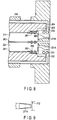
- FIG. 8 and FIG. 9 are sectional views of an example of an end of a rotor in an electric rotating machine in the second embodiment as viewed in the radial direction.
- the outer peripheries (side surfaces) of the center hole conductor ends 211A, 221A are each shaped like a cone such that the diameter of the outer periphery decreases consistently with the distance to the end of the shaft 20 as viewed from the machine interior side.
- the outer peripheries of the center hole conductor ends 211A, 221A have respective first inclinations to the center lines of the center hole conductor ends 211A, 221A parallel to the center of rotation L. That is, the outer peripheral surfaces (side surfaces) of the center hole conductor ends 211A, 221A, which correspond to protruding parts of the center hole conductors 211, 221, are inclined to the circumferential surfaces with respect to the center of rotation L.
- the shapes of the holes in the end conductors 212, 222 generally conform to the outer peripheries of the respective center hole conductor ends 211A, 221A, which are fitted into the holes in the end conductors 212, 222.
- the electric connection surface arranged on the inner peripheral surface of each of the holes formed in the end conductors 212, 222 has a second inclination smaller than the first inclination with respect to the center line of the hole parallel to the center of rotation L.
- the inner peripheral surfaces of the holes serving as the electric connection surfaces of the end conductors 212, 222 are inclined to the circumferential surfaces with respect to the center of rotation L.
- the bolts 231 and the nuts 232 can be attached to a side of each end conductor 212, 222 which has a smaller conical diameter, in other words, the side closer to the end of the rotor 2.
- the inclination (second inclination) of the inner periphery of the hole in the end conductor 212 is smaller than the inclination (first inclination) of the outer periphery of the center hole conductor 211A.
- the inclination of the inner periphery of the hole in the end conductor 222 is smaller than the inclination of the outer periphery of the center hole conductor 221A.
- the bolts 231 and the nuts 232 are arranged in an area of each of the end conductors 212, 222 which is closer to the end of the rotor 2. Consequently, when the bolts 231 and the nuts 232 start to be tightened in a direction in which the clearance between the hole in each of the end conductors 212, 222 and the outer periphery of the corresponding center hole conductor end 211A, 221A decreases, a contact surface pressure starts to be applied to the machine interior-side electric connection surface at a timing earlier than a timing when a contact surface pressure starts to be applied to the rotor end-side electric connection surface. Then, the bolts 231 and the nuts 232 are further tightened to finally apply the contact surface pressure to the entire electric connection surfaces.
- the electric connection surfaces corresponding to the inner peripheral surface of the hole in each end conductor and the outer peripheral surface of each of the center hole conductor ends are increased in size from the outside to inside of the center hole 201. Therefore, even when the bolts 231 and the nuts 232 are arranged only at the rotor end side where an operation of tightening the bolts 231 and the nuts 232 can be performed, the contact surface pressure can be applied even to the inside of the center hole 201. Thus, necessarily and sufficiently large electric connection surfaces can be provided.
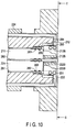
- FIG. 10 is a sectional view depicting an example of an end of a rotor in an electric rotating machine in the third embodiment as seen in the radial direction.
- FIG. 11 is a sectional view taken along line C-C in FIG. 10 and depicting the example of the end of the rotor in the electric rotating machine in the third embodiment.
- FIG. 12 is a perspective view depicting the example of the end of the rotor in the electric rotating machine in the third embodiment.
- a part of the outer periphery of each of the end conductors 212, 222 located near the electric connection surfaces of the end conductor 212, 222 and the corresponding center hole conductor end 211A, 221A is cylindrical.
- This cylindrical area is hereinafter referred to as a cylindrical part.
- Outer casings 212B, 222B having a higher rigidity than the material of the member of the cylindrical part can each be arranged over the corresponding cylindrical part on a one-to-one basis using the bolts 231 and the nuts 232.
- the outer casings 212B, 222B are, for example, spring steel.
- the end conductors 212, 222 are formed of a material such as copper which offers a small electric resistance. However, such a material does not have a high rigidity, and thus, the end conductors 212, 222 may be deformed.
- the rigidity of the end conductors 212, 222 is supplemented using the outer casings having a high rigidity as described above. Consequently, the shape of the cylindrical parts of the end conductors 212, 222 can be kept constant. Therefore, stable electric connection can be maintained between the inner peripheral surface of the hole in each end conductor 212, 222 and the outer peripheral surface of the corresponding center hole conductor 211A, 221A.
- FIG. 13 is a sectional view depicting an example of an end of a rotor in an electric rotating machine in the fourth embodiment as seen in the radial direction.
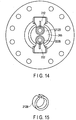
- FIG. 14 is a sectional view taken along line D-D in FIG. 13 and depicting the example of the end of the rotor in the electric rotating machine in the fourth embodiment.
- FIG. 15 is a perspective view depicting the example of the end of the rotor in the electric rotating machine in the fourth embodiment.
- the operation of fitting the center hole conductor ends 211A, 221A into the holes in the respective end conductors 212, 222 can be performed after the bore diameters of the outer casings 212B, 222B are expanded by, for example, inserting spacers into the slits in the outer casings 212B, 222B as described above, with the outer casings 212B, 222B placed over the outer peripheries of the cylindrical parts of the end conductors 212, 222 on a one-to-one basis.
- force is generated to restore the bore diameters of the outer casings 212B, 222B to the original state.
- this force is utilized to allow a contact surface pressure to be applied to the electric connection surfaces corresponding to the inner peripheral surface of the hole in each of the end conductors 212, 222 and the outer peripheral surface of the corresponding center hole conductor ends 211A, 221A.
- This method allows the contact surface pressure to be applied to the electric connection surfaces corresponding to the inner peripheral surface of the hole in each of the end conductors 212, 222 and the outer peripheral surface of the corresponding end 211A, 221A of the center hole conductor 211, 221 without using any bolts or nuts. This eliminates the need for an operation space for the operation of tightening bolts and nuts. Similar effects are expected to be able to be produced when the outer casings 212B, 222B described in the fourth embodiment are applied to the second embodiment.
- FIG. 16 is a sectional view depicting an example of an end of a rotor in an electric rotating machine in the second example as seen in the radial direction.
- FIG. 17 is a sectional view taken along line E-E in FIG. 16 and depicting the example of the end of the rotor in the electric rotating machine in the second example.
- a configuration in the second example includes center hole conductor ends 211B, 221B corresponding to the protruding parts of the center hole conductors 211, 221 which are closer to the end of the rotor, the center hole conductor ends 211B, 221B being formed by cutting out a part of the rotor end side of each of the center hole conductors 211, 221 which part is closer to the center of rotation L (that is, closer to the insulating board 262).
- each of the center hole conductors 211, 221 is spaced from a bottom surface thereof facing the insulating board 262, that is, a part of the side surface of each center hole conductor 211, 221 is spaced from the center of rotation L.
- This part serves as the center hole conductor end 211B, 221B corresponding to the protruding part located closer to the end of the rotor.
- the center hole conductor ends 211B, 221B are electrically insulated from each other and from the shaft 20.
- electric connection surfaces correspond to a first flat surface (on the center hole conductor 211) and a second flat surface (on the center hole conductor 221) which are included in the side surfaces of the center hole conductor ends 211B, 221B and which do not face the inner surface of the center hole 201.
- the first flat surface and the second flat surface are configured as surfaces which are spaced in a normal direction from the bottom surface of each center hole conductor facing the insulating board 262 and which are generally parallel to the bottom surface.
- the first flat surface and the second flat surface corresponding to the electric connection surfaces may be configured as surfaces located at a predetermined angle to the surface facing the insulating board 262 instead of the surfaces parallel to the surface facing the insulating board 262.
- the entire side surfaces of the center hole conductor ends 211B, 221B may serve as the electric connection surfaces.
- a recess is formed so as to stride across a straight line horizontal to the center of rotation L at which the insulating board 262 is disposed, as viewed from the end of the shaft 20.
- the recess is provided with the first flat surface of the center hole conductor 211 and the second flat surface of the center hole conductor 221. The flat surfaces face each other via a straight line horizontal to the center of rotation L at which the insulating board 262 is disposed.
- the end conductor 212 is provided with a generally L-shaped first end conductor protruding part having an electric connection surface connected to the first flat surface corresponding to an electric connection surface of the center hole conductor 211.
- the end conductor 222 is provided with a generally L-shaped second end conductor protruding part having an electric connection surface connected to the second flat surface corresponding to an electric connection surface of the center hole conductor 221.
- the first and second end conductor protruding parts are formed to provide a space near the center of rotation L where pressure wedges and a spring described below can be arranged when the first and second end conductor protruding parts are electrically connected to the first and second flat surfaces of the center hole conductors 211, 221 on a one-to-one basis.
- the pressure wedges which are electric insulators insulating the paired first and second end conductor protruding parts can each be arranged in a space between the first and second end conductor protruding parts.
- a pressure wedge 266A and a pressure wedge 266B are arranged in the space in the radial direction with a predetermined clearance between the pressure wedges 266A and 266B where the spring described below can be located.
- the pressure wedge 266A lies opposite to a surface of the first end conductor protruding part of the end conductor 212 which surface is closer to the center of rotation L, the end conductor 212 being electrically connected to the first flat surface of the protruding part of the center hole conductor 211.
- the pressure wedge 266B lies opposite to a surface of the second end conductor protruding part of the end conductor 222 which surface is closer to the center of rotation L, the end conductor 222 being electrically connected to the second flat surface of the protruding part of the center hole conductor 221.
- the pressure wedge 266A arranged as described above has the surface lying opposite to the first end conductor protruding part
- the pressure wedge 266B arranged as described above has the surface lying opposite to the second end conductor protruding part.
- These surfaces are formed as inclined surfaces having a predetermined inclination to the center of rotation L such that the distance from the center of rotation L to each of the surfaces increases from the rotor end side toward the machine interior side.
- the first end conductor protruding part has the surface lying opposite to the pressure wedge 266A
- the second end conductor protruding part has the surface lying opposite to the pressure wedge 266B.
- These surfaces are also formed as inclined surfaces having a predetermined inclination equal to the inclination of the pressure wedges 266A, 266B such that the distance from the center of rotation L to each of the surfaces increases from the rotor end side toward the machine interior side.
- the bolt 231 is screwed into each of the end conductors 212, 222 in the axial direction.
- the screwing allows the end conductors 212, 222 to be pushed from the end of the shaft 20 toward the machine interior side.
- Each of the inclined surfaces of the pressure wedges 266A, 266B is subjected to force to compress the spring 243 between the pressure wedges 266A, 26B. This causes the spring 243 to exert a repulsive force.
- the repulsive force allows a contact surface pressure to be applied to the electric connection surfaces of the end conductor 212 and the rotor end side of the center hole conductor 211 and to the electric connection surfaces of the end conductor 222 and the rotor end side of the center hole conductor 221.
- the second example can produce effects similar to the effects of the first embodiment even if an air cooled electric rotating machine which needs no gas structure is used.
Landscapes
- Engineering & Computer Science (AREA)
- Power Engineering (AREA)
- Manufacturing & Machinery (AREA)
- Motor Or Generator Frames (AREA)
- Motor Or Generator Cooling System (AREA)
- Manufacture Of Motors, Generators (AREA)
- Windings For Motors And Generators (AREA)
Description
- Embodiments described herein relate generally to an electric rotating machine and a manufacturing method for an electric rotating machine.
- A driving machine is connected to one end of a rotor of an electric rotating machine. To excite a core of the rotor, external power is supplied to a collector ring installed at the other end of the rotor. The power is supplied to a rotor coil through studs inserted into holes formed in a shaft in a radial direction and center hole conductors inserted into a center hole in the shaft. An increased output from the electric rotating machine also increases power supplied to the rotor coil, so that a current flowing through the rotor coil also increases. In order to improve thermal efficiency of facilities, a system has recently been beginning to be adopted in which driving machines are connected to opposite ends of the rotor of the electric rotating machine to transmit a driving torque to the rotor through the end of the rotor at which the collector ring is provided. The use of this system involves a high transmission torque applied to an end of a side of the rotor from which power is fed to a field circuit.
- Also in a system in which no collector ring is provided and a brushless exciting apparatus is connected instead to the end of the rotor to enhance maintanability, an output from the brushless exciting apparatus increases with the electric rotating machine output increase and as a result transmission torque increases.
- For the above-described increased current, each part of the current circuit can be settled increasing sectional area. For example, for the studs, a sufficient sectional area can be provided according to the increased current by increasing the diameter of each of the studs or the number of the studs to increase the sectional area of the current circuit. However, the shaft needs to have shear strength sufficient to resist a transmission torque applied to the rotor, so the holes which extend from the center hole in the shaft to an outer periphery of the shaft for studs are inhibited from being formed in the shaft depending on the magnitude of the torque. In addition, the diameter of the shaft is inhibited from being increased to increase the shearing strength at the end of the rotor at which the collector ring with a peripheral speed limit is provided.
- In a structure that eliminates the need for the radial holes for studs as disclosed in
JP 2013017307 A - However, in this structure, a contact area necessary and sufficient to accommodate the increased current fail to be provided simply by using the area of the end surfaces of the center hole conductors.
-
JP 2013017307 A -
EP 0645874 A1 discloses an electrical machine with collector rings installed around an outer periphery of a protruding stump of a rotating machine shaft and a pair of conductors inserted into a center hole formed in the machine shaft and the stump in a direction along a rotation center. The protruding stump is releasably connected to the machine shaft in an axial direction by means of a coupling. -
DE 951465 C discloses a gas-tight supply of electric current to coils of a gas-cooled generator. The generator has a pair of collector rings and the electrical connection with the coils inside the generator casing is made through a pair of rod-like extensions connected to an external electrical conductor at a position outside of the casing in that the outside ends of the rod-like extensions are expanded to form a conical insert piece onto which a mating contact piece of the electrical conductor is inserted and secured by an axial bolt. -
JP H0350965 U -
GB 879165 A - The object of the present invention is to provide an electric rotating machine and a manufacturing method for an electric rotating machine in which center hole conductors configured to supply power to a rotor coil can be electrically connected to conductors located outside the center hole with a sufficient contact area provided between the center hole conductors and the conductors outside the center hole.
- In general, according to the invention, there is provided a gas cooled electric rotating machine with the features of
claim 1 in which a cooling gas is flowed through into a rotor and a stator. The rotor includes a shaft having a center hole formed along a center of rotation of the rotor and a hole for studs formed at a machine interior side of the center hole so as to extend in a radial direction from the center hole to an outer peripheral surface of the rotor to allow the center hole and the outer peripheral surface to communicate with each other. The rotor includes a pair of center hole conductors inserted into the center hole along the center of rotation while being electrically insulated from the shaft and from each other, the center hole conductors including respective protruding parts protruding toward an end of the shaft. The rotor includes a pair of end conductors provided at the end of the shaft so as to be each electrically insulated from the shaft, the end conductors being electrically connected to side surfaces of the protruding parts of the pair of center hole conductors, the side surfaces serving as electric connection surfaces. - The invention also provides a manufacturing method for an electric rotating machine with the features of
claim 4. - The invention can be more fully understood from the following detailed description when taken in conjunction with the accompanying drawings, in which:
-
FIG. 1 is a diagram depicting an example of an electric rotating machine in the first embodiment; -
FIG. 2 is sectional view depicting an example of an end of a rotor of the electric rotating machine in a first embodiment; -
FIG. 3 is sectional view depicting an example of an end of a rotor of the electric rotating machine in the first embodiment; -
FIG. 4 is a sectional view taken along line B-B inFIG. 2 and depicting the example of the end of the rotor in the electric rotating machine in the first embodiment; -
FIG. 5 is a perspective view of an end conductor depicted of a rotor of the electric rotating machine in the first embodiment; -
FIG. 6 is a perspective view of an end conductor depicted of a rotor of the electric rotating machine in the first embodiment; -
FIG. 7 is sectional view depicting an example of an end of a rotor of the electric rotating machine in a first example serving to explain aspects of the invention; -
FIG. 8 is sectional view depicting an example of an end of a rotor of the electric rotating machine in a second embodiment; -
FIG. 9 is sectional view depicting an example of an end of a rotor of the electric rotating machine in the second embodiment; -
FIG. 10 is sectional view depicting an example of an end of a rotor of the electric rotating machine in a third embodiment; -
FIG. 11 is a sectional view taken along line C-C inFIG. 10 and depicting the example of the end of the rotor in the electric rotating machine in the third embodiment; -
FIG. 12 is a perspective view depicting the example of the end of the rotor in the electric rotating machine in the third embodiment; -
FIG. 13 is a sectional view depicting an example of an end of a rotor in an electric rotating machine in a fourth embodiment; -
FIG. 14 is a sectional view taken along line D-D inFIG. 13 and depicting the example of the end of the rotor in the electric rotating machine in the fourth embodiment; -
FIG. 15 is a perspective view depicting the example of the end of the rotor in the electric rotating machine in the fourth embodiment; -
FIG. 16 is a sectional view depicting an example of an end of a rotor in an electric rotating machine in the second example which is not part of the invention serving to explain aspects of the invention; and -
FIG. 17 is a sectional view taken along line E-E inFIG. 16 and depicting the example of the end of the rotor in the electric rotating machine in the second example. - Embodiments will be explained below with reference to the accompanying drawings.
- First, an electric rotating machine in a first embodiment will be described with reference to
FIG. 1, FIG. 2 ,FIG. 3 ,FIG. 4, FIG. 5 , andFIG. 6 .FIG. 1 is a diagram depicting an example of an electric rotating machine in the first embodiment.FIG. 2 ,FIG. 3 , andFIG. 4 are sectional views depicting an example of an end of a rotor of the electric rotating machine in the first embodiment.FIG. 3 is an enlarged view of a portion A depicted inFIG. 2 .FIG. 4 is a sectional view taken along line B-B inFIG. 2 .FIG. 5 is a perspective view of an end conductor depicted inFIG. 2 .FIG. 6 is a perspective view of a center hole conductor depicted inFIG. 2 . - An
electric rotating machine 1 depicted inFIG. 1 is a gas-cooled electric rotating machine in which a cooling gas is flowed through into arotor 2 and astator 3. - The
stator 3 arranged on an outer periphery of therotor 2 is attached to an inner surface of a stator frame (frame) 4. An end (to which a power feeding apparatus is connected) 2A of therotor 2 extends through thestator frame 4 and is supported by a bearing 5 to seal, at a position closer to the center of the stator than the bearing 5, the cooling gas in thestator frame 4 with anoil seal 6. - A
coil 7 installed on therotor 2 to excite acore part 2B of therotor 2 is externally supplied with power viacollector rings end 2A. - As depicted in
FIG. 2 , therotor 2 of theelectric rotating machine 1 includes as a main component ashaft 20 with acenter hole 201 formed in a central part thereof. Therotor 2 further includes as field circuit components therotor coil 7,center hole conductors end conductors radial studs center hole conductor 211, theend conductor 212, and theradial stud 213 are positioned 180° away from thecenter hole conductor 221, theend conductor 222, and theradial stud 223 symmetrically with respect to a center of rotation L. - As depicted in
FIG. 2 , therotor 2 hascollector rings collector rings shaft 20 extending outward of thestator frame 4. The collector rings 214, 224 are installed in juxtaposition in an axial direction of theshaft 20 so as to be insulated from theshaft 20 using an insulating member. Outer peripheral surfaces of the collector rings 214, 224 are electrically connected together by slidable movement with a power feeding brush. The insulation described below is electric insulation. - The
center hole 201 andholes 202 for studs located at a machine interior side are formed at theend 2A. Thecenter hole 201 is formed along the center of rotation L. Theholes 202 for studs are located near therotor coil 7 and extend in a radial direction so as to allow thecenter hole 201 to communicate with an outer peripheral surface of theshaft 20. As depicted inFIG. 2 , theholes 202 for studs are formed line-symmetrically with respect to the center of rotation L, that is, 180° away from each other in a circumferential direction. - The pair of
center hole conductors center hole 201 along the center of rotation L so as to be electrically insulated from theshaft 20 and from each other. - An insulating
board 262 is interposed between thecenter hole conductors center hole conductors pipe 261 for the center hole conductors is installed between an inner periphery of the center hole 201 (which faces thecenter hole conductors 211, 221) and thecenter hole conductors block 263 is interposed between theend 2A and the pair ofend conductors - An insulating
board 264 is interposed between theend conductor 212 and an end surface of theshaft 20 so as to electrically insulate theend conductor 212 from the end surface. The insulatingboard 264 is also interposed between theend conductor 222 and theshaft 20. -
Radial studs holes 202 for studs, located 180° away from each other and insulated from theshaft 20. Theradial stud 213 electrically connects alead conductor 7A of therotor coil 7 and thecenter hole conductor 211 together. Similarly, theradial stud 223 electrically connects alead conductor 7B of therotor coil 7 and thecenter hole conductor 221 together. - The
radial stud 213 is connected to an end of therotor coil 7 via thelead conductor 7A. Therotor coil 7 is prepared as one of bend parts not depicted in the drawings. Similarly, theradial stud 223 is connected to the end of therotor coil 7 via thelead conductor 7B. - The
lead conductors shaft 20. - As depicted in
FIG. 2 , at the end of theshaft 20, theend conductors - The collector rings 214, 224 are installed on the outer periphery of the end of the
shaft 20 via an insulatingpipe 271 for the collector rings. The collector rings 214, 224 are electrically connected together by slidable movement with the power feeding brush. The power feeding brush is attached to a power feeding apparatus installed outside of the collector rings 214, 224. - As depicted in
FIG. 3 , at an end of thecenter hole 201, an insulatingplug 265 is housed which has through-holes center hole conductor plug 265 is located at center hole conductor ends 211A, 221A to electrically insulate theshaft 20 from thecenter hole conductors - A
gasket 281 is fitted into a groove in an outer peripheral surface of an end of the center hole conductor 211 (more specifically, a part of thecenter hole conductor 211 located at the machine interior side with respect to the center hole conductor end 211A, which serves as a part of thecenter hole conductor 211 protruding toward the end of the shaft 20) so as to extend in the axial direction; the groove is formed so as to face an inner periphery of the through-hole 265A in the insulatingplug 265. Consequently, a gas seal is formed between the outer peripheral surface of the end of thecenter hole conductor 211 and the insulatingplug 265. - Similarly, a
gasket 282 is fitted into a groove in an outer peripheral surface of an end of the center hole conductor 221 (more specifically, a part of thecenter hole conductor 221 located at the machine interior side with respect to the center hole conductor end 221A, which serves as a part of thecenter hole conductor 221 protruding toward the end of the shaft 20) so as to extend in the axial direction; the groove is formed so as to face an inner periphery of the through-hole 265B in the insulatingplug 265. Consequently, a gas seal is formed between the above-described outer peripheral surface and the insulatingplug 265. - A
gasket 283 is fitted into a groove formed in an outer periphery of the insulatingplug 265 such that thegasket 283 extends in the axial direction. In other words, thegasket 283 is arranged between the insulatingplug 265 and thecenter hole 201 so as to extend in the axial direction. Consequently, a gas seal is formed between the insulatingplug 265 and an inner peripheral surface of thecenter hole 201. - In other words, the
gaskets plug 265 and between the insulatingplug 265 and thecenter hole 201 in theshaft 20 and to seal the cooling gas. - In the first embodiment, the center hole conductor ends 211A, 221A, which serve as protruding parts, are cylindrically formed. In the first embodiment, a hole is formed in the
end conductor 212 so that the centerhole conductor end 211A is fitted into the hole. When a part of an outer peripheral surface of the center hole conductor end 211A (a side surface, that is, a surface with a circumferential component such as a circumferential surface with respect to a center line of the centerhole conductor end 211A parallel to the center of rotation L) located at the end of the shaft serves as an electric connection surface, an inner peripheral surface of the above-described hole is connected to the electric connection surface. The hole has a bore diameter approximately equal to the outside diameter of the centerhole conductor end 211A. The hole is formed to extend in the axial direction so as to have an axial length equal to the axial length of the outer peripheral surface of the centerhole conductor end 211A. - Similarly, a hole is formed in the
end conductor 222 so that the centerhole conductor end 221A is fitted into the hole. When a part of an outer peripheral surface of the center hole conductor end 221A (a side surface, that is, a surface with a circumferential component such as a circumferential surface with respect to a center line of the centerhole conductor end 221A parallel to the center of rotation L) located at the end of the shaft serves as an electric connection surface, an inner peripheral surface of the above-described hole is connected to the electric connection surface. The hole has a bore diameter approximately equal to the outside diameter of the centerhole conductor end 221A. The hole is formed to extend in the axial direction so as to have an axial length equal to the axial length of the outer peripheral surface of the centerhole conductor end 221A. An inner peripheral surface of the hole formed in theend conductor 212 serves as an electric connection surface of theend conductor 212. Similarly, an inner peripheral surface of the hole formed in theend conductor 222 serves as an electric connection surface of theend conductor 222. - A
slit 212A (in the end conductor 212) is formed in theend conductor 212 so as to communicate with the hole into which the centerhole conductor end 211A is fitted. Similarly, aslit 222A (in the end conductor 222) is formed in theend conductor 222 so as to communicate with the hole into which the centerhole conductor end 221A is fitted. - With the outer peripheral surfaces of the center hole conductor ends 211A, 221A fitted in the holes in the
respective end conductor bolts 231 andnuts 232 can be attached to each of theend conductors end conductor - The
bolts 231 and thenuts 232 are tightening members intended to reduce the clearance (width) between theslits slits slits slits end conductor 212 and to (2) the electric connection surfaces corresponding to the outer peripheral surface of the center hole conductor end 221A and the inner peripheral surface of the hole in theend conductor 222. - Specifically, as depicted in
FIG. 3 , theend conductor 212 is arranged closer to the end of theshaft 20 than the insulatingplug 265. A cylindrical hole is formed in theend conductor 212 so that thecylindrical end 211A of the center hole conductor 211 (seeFIG. 6 ) is fitted into the cylindrical hole. As depicted inFIG. 4 and FIG. 5 , theslit 212A is formed in a part of the hole. - Similarly, as depicted in
FIG. 3 , theend conductor 222 is arranged closer to the end of theshaft 20 than the insulatingplug 265. A cylindrical hole is formed in theend conductor 222 so that thecylindrical end 221A is fitted into the cylindrical hole. As depicted inFIG. 4 , theslit 222A is formed in a part of the hole. - Now, with the center hole conductor ends 211A, 221A fitted in the
end conductors slits bolts 231 and the nuts 232. Consequently, the bore diameters of the holes in theend conductors end conductor 212 and the outer peripheral surface of theend 211A of thecenter hole conductor 211 and to the entire contact surfaces corresponding to the inner peripheral surface of the hole in theend conductor 222 and the outer peripheral surface of theend 221A of thecenter hole conductor 221. This allows a sufficiently large electric connection surface to be provided in a narrow space in thecenter hole 201. - In the electric
rotating machine 1 in the first embodiment configured as described above, a field current from the a positive-electrode-side power feeding brush electrically connected to the outer periphery of thecollector ring 214 by slidable movement is fed to therotor coil 7 through theend conductor 212, thecenter hole conductor 211, and theradial stud 213 via thelead conductor 7A. The current then flows via thelead conductor 7B through theradial stud 223, thecenter hole conductor 221, and theend conductor 222 to return to the negative-electrode-side power feeding brush electrically connected to the outer periphery of thecollector ring 224 by slidable movement. - The field current excites the
core part 2B of therotor 2. Therotor 2 is rotated by an external driving force exerted by a steam turbine etc., to generate an electromotive force in the stator, leading to power generation. - Therefore, in the first embodiment, a contact surface pressure can be efficiently and uniformly applied to (1) the entire contact surfaces corresponding to the inner peripheral surface of the hole in the
end conductor 212 and the outer peripheral surface of the center hole conductor end 211A and to (2) the entire contact surfaces corresponding to the inner peripheral surface of the hole in theend conductor 222 and the outer peripheral surface of the center hole conductor end 221A without the need to significantly increase the sizes of thebolts 231 or the number of thebolts 231. - In the present embodiment, in the configuration in which the
end conductors end 2A of therotor 2, the contact area for electric connection can be substantially increased consistently with the current value even in the narrow space at the end of thecenter hole 201 without the need to form any radial hole other than theholes 202 for studs in theshaft 20. - When, for example, the electric
rotating machine 1 provides a high output, theradial studs - Now, a first example will be described with reference to the drawings. A basic configuration of the
rotor 2 in the electricrotating machine 1 in embodiments and examples described below is the same as the corresponding configuration in the first embodiment. Thus, components having the same functions throughout the examples and embodiments have the same reference numerals throughout the drawings. For detailed description of these components, the description and drawings of the first embodiment may be referred to for comparison. - Instead of the configuration in which the collector rings 214, 224 come into contact with each other based on slidable movement of the brush, the first example has a configuration in which a brushless exciting apparatus is used to supply a field current to the
rotor coil 7 of therotor 2. -
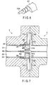
FIG. 7 is a sectional view depicting an example of the end of the rotor in the electric rotating machine in the first example. As depicted inFIG. 7 , in the first example, arotor 9 in a brushless exciting apparatus is coupled to the end surface of therotor 2 via a shaft coupling to electrically connect theend conductors output conductors rotor 9 in the brushless exciting apparatus on a one-to-one basis. Consequently, the brushless exciting apparatus can supply a field current to therotor coil 7 of therotor 2. - In other words, electric connection surfaces corresponding to end surfaces of the
output conductors rotor 9 in the brushless exciting apparatus are coupled to the end surface of therotor 2 in the electricrotating machine 1 via the shaft coupling. Thus, a contact surface pressure is applied to the electric connection surfaces corresponding to the end surfaces of theend conductors output conductors end conductor 212 and theoutput conductors 312 together while electrically connecting theend conductor 222 and theoutput conductor 322 together. - Consequently, when the brushless exciting apparatus is used, the contact area for electric connection can also be significantly increased consistently with the current value.
- A higher contact surface pressure can be applied to the electric connection surfaces by, for example, installing
springs 343 on a back side of theoutput conductors output conductors - Now, a second embodiment will be described with reference to
FIG. 8 and FIG. 9 . -
FIG. 8 and FIG. 9 are sectional views of an example of an end of a rotor in an electric rotating machine in the second embodiment as viewed in the radial direction. - In the second embodiment, the outer peripheries (side surfaces) of the center hole conductor ends 211A, 221A are each shaped like a cone such that the diameter of the outer periphery decreases consistently with the distance to the end of the
shaft 20 as viewed from the machine interior side. In the second embodiment, the outer peripheries of the center hole conductor ends 211A, 221A have respective first inclinations to the center lines of the center hole conductor ends 211A, 221A parallel to the center of rotation L. That is, the outer peripheral surfaces (side surfaces) of the center hole conductor ends 211A, 221A, which correspond to protruding parts of thecenter hole conductors - The shapes of the holes in the
end conductors end conductors end conductors end conductors - With the
ends center hole conductors respective end conductors end conductors center hole conductor - In the second embodiment, to reduce the clearance, the
bolts 231 and thenuts 232 can be attached to a side of eachend conductor rotor 2. - Specifically, as depicted in
FIG. 8 and FIG. 9 , in the third embodiment, the inclination (second inclination) of the inner periphery of the hole in theend conductor 212 is smaller than the inclination (first inclination) of the outer periphery of thecenter hole conductor 211A. The inclination of the inner periphery of the hole in theend conductor 222 is smaller than the inclination of the outer periphery of thecenter hole conductor 221A. - The
bolts 231 and thenuts 232 are arranged in an area of each of theend conductors rotor 2. Consequently, when thebolts 231 and thenuts 232 start to be tightened in a direction in which the clearance between the hole in each of theend conductors bolts 231 and thenuts 232 are further tightened to finally apply the contact surface pressure to the entire electric connection surfaces. - As described above, in the second embodiment, for a further increase in field current, the electric connection surfaces corresponding to the inner peripheral surface of the hole in each end conductor and the outer peripheral surface of each of the center hole conductor ends are increased in size from the outside to inside of the
center hole 201. Therefore, even when thebolts 231 and thenuts 232 are arranged only at the rotor end side where an operation of tightening thebolts 231 and thenuts 232 can be performed, the contact surface pressure can be applied even to the inside of thecenter hole 201. Thus, necessarily and sufficiently large electric connection surfaces can be provided. - Now, a third embodiment will be described with reference to
FIG. 10 ,FIG. 11, and FIG. 12 .FIG. 10 is a sectional view depicting an example of an end of a rotor in an electric rotating machine in the third embodiment as seen in the radial direction.FIG. 11 is a sectional view taken along line C-C inFIG. 10 and depicting the example of the end of the rotor in the electric rotating machine in the third embodiment.FIG. 12 is a perspective view depicting the example of the end of the rotor in the electric rotating machine in the third embodiment. - As depicted in
FIG. 10 andFIG. 11 , in the third embodiment, a part of the outer periphery of each of theend conductors end conductor Outer casings bolts 231 and the nuts 232. Theouter casings - In general, the
end conductors end conductors - In the third embodiment, the rigidity of the
end conductors end conductors end conductor center hole conductor - Similar effects are expected to be able to be produced when the
outer casings - Now, a fourth embodiment will be described with reference to
FIG. 13 ,FIG. 14, and FIG. 15 .FIG. 13 is a sectional view depicting an example of an end of a rotor in an electric rotating machine in the fourth embodiment as seen in the radial direction.FIG. 14 is a sectional view taken along line D-D inFIG. 13 and depicting the example of the end of the rotor in the electric rotating machine in the fourth embodiment.FIG. 15 is a perspective view depicting the example of the end of the rotor in the electric rotating machine in the fourth embodiment. - As depicted in
FIG. 13 ,FIG. 14, and FIG. 15 , the fourth embodiment does not use thebolts 231 or thenuts 232 as described in the third embodiment. In the fourth embodiment, slits are formed in the respective outer casings, with spacers inserted into the respective slits. This allows the bore diameters of theouter casings outer casings respective end conductors - The
outer casings outer casings respective end conductors outer casings outer casings corresponding end conductor respective end conductors outer casings - The operation of fitting the center hole conductor ends 211A, 221A into the holes in the
respective end conductors outer casings outer casings outer casings end conductors respective end conductors outer casings - When the spacers are drawn out from the slits in the
outer casings outer casings end conductors - This method allows the contact surface pressure to be applied to the electric connection surfaces corresponding to the inner peripheral surface of the hole in each of the
end conductors corresponding end center hole conductor outer casings - Now, a second example will be described with reference to
FIG. 16 andFIG. 17 .FIG. 16 is a sectional view depicting an example of an end of a rotor in an electric rotating machine in the second example as seen in the radial direction.FIG. 17 is a sectional view taken along line E-E inFIG. 16 and depicting the example of the end of the rotor in the electric rotating machine in the second example. - Unlike the configuration including the cylindrical center hole conductor ends 211A, 221A which correspond to protruding parts and the side surfaces of which serve as electric connection surfaces fitted into the holes formed in the respective end conductors as described in the first embodiment, a configuration in the second example includes center hole conductor ends 211B, 221B corresponding to the protruding parts of the
center hole conductors center hole conductors center hole conductors board 262, that is, a part of the side surface of eachcenter hole conductor hole conductor end shaft 20. - In the present example, a part of the side surface of each of the center hole conductor ends 211B, 221B which part is closer to the center of rotation L is cut out. In this configuration, electric connection surfaces correspond to a first flat surface (on the center hole conductor 211) and a second flat surface (on the center hole conductor 221) which are included in the side surfaces of the center hole conductor ends 211B, 221B and which do not face the inner surface of the
center hole 201. In particular, in the present example, the first flat surface and the second flat surface are configured as surfaces which are spaced in a normal direction from the bottom surface of each center hole conductor facing the insulatingboard 262 and which are generally parallel to the bottom surface. The first flat surface and the second flat surface corresponding to the electric connection surfaces may be configured as surfaces located at a predetermined angle to the surface facing the insulatingboard 262 instead of the surfaces parallel to the surface facing the insulatingboard 262. Alternatively, the entire side surfaces of the center hole conductor ends 211B, 221B may serve as the electric connection surfaces. - That is, in the present example, when the
center hole conductors board 262, are inserted into thecenter hole 201 along the center of rotation L, a recess is formed so as to stride across a straight line horizontal to the center of rotation L at which the insulatingboard 262 is disposed, as viewed from the end of theshaft 20. The recess is provided with the first flat surface of thecenter hole conductor 211 and the second flat surface of thecenter hole conductor 221. The flat surfaces face each other via a straight line horizontal to the center of rotation L at which the insulatingboard 262 is disposed. - The
end conductor 212 is provided with a generally L-shaped first end conductor protruding part having an electric connection surface connected to the first flat surface corresponding to an electric connection surface of thecenter hole conductor 211. Theend conductor 222 is provided with a generally L-shaped second end conductor protruding part having an electric connection surface connected to the second flat surface corresponding to an electric connection surface of thecenter hole conductor 221. - The first and second end conductor protruding parts are formed to provide a space near the center of rotation L where pressure wedges and a spring described below can be arranged when the first and second end conductor protruding parts are electrically connected to the first and second flat surfaces of the
center hole conductors - That is, the pressure wedges which are electric insulators insulating the paired first and second end conductor protruding parts can each be arranged in a space between the first and second end conductor protruding parts. Specifically, a
pressure wedge 266A and apressure wedge 266B are arranged in the space in the radial direction with a predetermined clearance between thepressure wedges - The
pressure wedge 266A lies opposite to a surface of the first end conductor protruding part of theend conductor 212 which surface is closer to the center of rotation L, theend conductor 212 being electrically connected to the first flat surface of the protruding part of thecenter hole conductor 211. - The
pressure wedge 266B lies opposite to a surface of the second end conductor protruding part of theend conductor 222 which surface is closer to the center of rotation L, theend conductor 222 being electrically connected to the second flat surface of the protruding part of thecenter hole conductor 221. - Thus, the
pressure wedge 266A arranged as described above has the surface lying opposite to the first end conductor protruding part, and thepressure wedge 266B arranged as described above has the surface lying opposite to the second end conductor protruding part. These surfaces are formed as inclined surfaces having a predetermined inclination to the center of rotation L such that the distance from the center of rotation L to each of the surfaces increases from the rotor end side toward the machine interior side. - A
spring 243 can be inserted into the clearance between thepressure wedges - As described above, the first end conductor protruding part has the surface lying opposite to the
pressure wedge 266A, and the second end conductor protruding part has the surface lying opposite to thepressure wedge 266B. These surfaces are also formed as inclined surfaces having a predetermined inclination equal to the inclination of thepressure wedges - In the second example, the
bolt 231 is screwed into each of theend conductors end conductors shaft 20 toward the machine interior side. Each of the inclined surfaces of thepressure wedges spring 243 between thepressure wedges 266A, 26B. This causes thespring 243 to exert a repulsive force. The repulsive force allows a contact surface pressure to be applied to the electric connection surfaces of theend conductor 212 and the rotor end side of thecenter hole conductor 211 and to the electric connection surfaces of theend conductor 222 and the rotor end side of thecenter hole conductor 221. - As described above, the second example can produce effects similar to the effects of the first embodiment even if an air cooled electric rotating machine which needs no gas structure is used.
Claims (4)
- A gas cooled electric rotating machine in which, in operation, a cooling gas is flowed through into a rotor (2) and a stator (3),
wherein the rotor (2) comprises:a shaft (20) having a center hole (201) formed along a center of rotation (L) of the rotor (2);a pair of collector rings (214,224) installed around an outer periphery of the shaft (20);a hole (202) for studs (213,223) formed at a machine interior side of the center hole (201) so as to extend in a radial direction from the center hole (201) to an outer peripheral surface of the rotor (2) to allow the center hole (201) and the outer peripheral surface to communicate with each other;a pair of center hole conductors (211,221) inserted into the center hole (201) along the center of rotation (L) while being electrically insulated from the shaft (20) and from each other, the center hole conductors (211,221) including respective end parts (211A,221A) extending along an axial direction of an end of the shaft (20), wherein each of the end parts (211A,221A) comprises a circumferential surface with respect to a center line of the end parts (211A,221A) parallel to the center of rotation (L), said circumferential surface serving as an electric connection surface; anda pair of end conductors (212,222) provided at the end of the shaft (20) so as to be each electrically insulated from the shaft (20),wherein each of the end conductors (212,222) has a hole so that the respective end part (211A,221A) can be fitted into the hole and electrically connected thereto in that an inner peripheral surface of the hole is connected to the circumferential surface of the respective end part (211A,221A) of the pair of center hole conductors (211,221),wherein each of the end conductors (212,222) is electrically connected to a respective one of the pair of collector rings (214,224),wherein the end conductors (212,222) are provided with respective slits (212A,222A) which communicate with the corresponding holes, and
the end conductors being further provided with tightening members (231, 232), and
wherein the slits (212A,222A) are formed so as to enable a width between the slits (212A,222A) to be reduced using the 10 tightening members (231,232). - The electric rotating machine according to claim 1, wherein
circumferential surfaces of the end parts (211A,221A) at ends of the center hole conductors (211,221) are inclined with respect to the center between the end parts (211A,221A). - The electric rotating machine according to claim 1 or 2, further comprising:an insulating plug (265) located at ends of the center hole conductors (211,221) to electrically insulate the center hole conductors (211,221) from the shaft (20) and to seal the cooling gas; andgaskets (281,282,283) arranged in the axial direction between the end of each of the center hole conductors (211,221) and the insulating plug (265) and between the insulating plug (265) and the center hole (201) in the shaft (20) to seal the cooling gas.
- A manufacturing method for a gas cooled electric rotating machine in which, in operation, a cooling gas is flowed through into a rotor (2) and a stator (3), the manufacturing method comprising:preparing a rotor (2) comprising a shaft (20) having a center hole (201) formed along a center of rotation (L) of the rotor (2), a pair of collector rings (214,224) installed around an outer periphery of the shaft (20), and a hole (202) for studs (213,223) formed at a machine interior side of the center hole (201) so as to extend in a radial direction from the center hole (201) to an outer peripheral surface of the rotor (2) to allow the center hole (201) and the outer peripheral surface to communicate with each other;inserting a pair of center hole conductors (211,221) including respective end parts (211A,221A) extending along an axial direction of an end of the shaft (20), into the center hole (201) along the center of rotation (L) such that the center hole conductors (211,221) are electrically insulated from the shaft (20) and from each other, wherein each of the end parts (211A,221A) comprises a circumferential surface with respect to a center line of the end parts (211A,221A) parallel to the center of rotation (L), said circumferential surface serving as an electric connection surface;electrically connecting a pair of end conductors (212,222) provided at the end of the shaft (20) , which are electrically insulated from the shaft (20) and are electrically connected to a respective one of the pair of collector rings (214,224), to the circumferential surfaces of the end parts (211A,221A) of the pair of center hole conductors (211,221), respectively, wherein in each of the end parts (211A,221A) is fitted into a hole of the respective end conductor (212,222) and is electrically connected thereto, wherein in an inner peripheral surface of the hole is connected to the circumferential surface of the respective end part (211A,221A)
, wherein the end conductors (212,222) are provided with respective slits (212A,222A) which communicate with the corresponding holes, and wherein the slits (212A,222A) are formed so as to enable a width between the slits (212A,222A) to be reduced using tightening members (231,232).
Applications Claiming Priority (1)
| Application Number | Priority Date | Filing Date | Title |
|---|---|---|---|
| JP2016087020A JP6689125B2 (en) | 2016-04-25 | 2016-04-25 | Rotating electric machine and method of manufacturing rotating electric machine |
Publications (2)
| Publication Number | Publication Date |
|---|---|
| EP3240146A1 EP3240146A1 (en) | 2017-11-01 |
| EP3240146B1 true EP3240146B1 (en) | 2021-11-10 |
Family
ID=58606171
Family Applications (1)
| Application Number | Title | Priority Date | Filing Date |
|---|---|---|---|
| EP17167714.9A Active EP3240146B1 (en) | 2016-04-25 | 2017-04-24 | Electric rotating machine and manufacturing method for electric rotating machine |
Country Status (5)
| Country | Link |
|---|---|
| US (1) | US10601282B2 (en) |
| EP (1) | EP3240146B1 (en) |
| JP (1) | JP6689125B2 (en) |
| KR (1) | KR101811224B1 (en) |
| CN (1) | CN107306062B (en) |
Families Citing this family (2)
| Publication number | Priority date | Publication date | Assignee | Title |
|---|---|---|---|---|
| JP6563378B2 (en) * | 2016-11-04 | 2019-08-21 | 株式会社東芝 | Automatic voltage regulator, automatic voltage regulation method, automatic voltage regulation program, generator excitation system and power generation system |
| EP3599678A1 (en) * | 2018-07-27 | 2020-01-29 | Siemens Aktiengesellschaft | Slip ring, slip ring unit, electric machine and wind turbine |
Citations (4)
| Publication number | Priority date | Publication date | Assignee | Title |
|---|---|---|---|---|
| DE951465C (en) * | 1953-07-12 | 1956-10-31 | Licentia Gmbh | Gas-tight power supply to the excitation winding for gas-cooled generators |
| GB879165A (en) * | 1959-01-21 | 1961-10-04 | Gen Electric | Improvements in or relating to gas-tight sealing assemblies for dynamo-electric machines |
| JPS5511782U (en) * | 1978-07-10 | 1980-01-25 | ||
| JPH0350965U (en) * | 1989-09-25 | 1991-05-17 |
Family Cites Families (10)
| Publication number | Priority date | Publication date | Assignee | Title |
|---|---|---|---|---|
| JPS5628795Y2 (en) | 1977-06-14 | 1981-07-08 | ||
| US5015895A (en) * | 1990-01-04 | 1991-05-14 | Westinghouse Electric Corp. | Insulated, gas tight electrical lead conductor |
| CH682610A5 (en) * | 1991-10-01 | 1993-10-15 | Asea Brown Boveri | Rotor of an electric machine having an excitation current supply line. |
| DE4141690A1 (en) * | 1991-12-18 | 1993-06-24 | Asea Brown Boveri | ROTOR OF AN ELECTRICAL MACHINE WITH AN EXCITING POWER SUPPLY |
| DE4333094A1 (en) * | 1993-09-29 | 1995-03-30 | Abb Management Ag | Excitation current line in the rotor of an electrical machine |
| EP2341599A1 (en) * | 2010-01-05 | 2011-07-06 | Alstom Technology Ltd | Improved sealed electric generator |
| JP2012120312A (en) | 2010-11-30 | 2012-06-21 | Nippon Densan Corp | Rotary electric machine and method for manufacturing rotary electric machine |
| JP5755521B2 (en) | 2011-07-04 | 2015-07-29 | 株式会社東芝 | Rotating electric machine |
| JP5992149B2 (en) | 2011-07-05 | 2016-09-14 | 株式会社東芝 | Rotating electric machine and method of manufacturing rotating electric machine |
| JP6353738B2 (en) | 2014-08-20 | 2018-07-04 | 株式会社日立製作所 | Rotating electric machine |
-
2016
- 2016-04-25 JP JP2016087020A patent/JP6689125B2/en active Active
-
2017
- 2017-04-04 KR KR1020170043528A patent/KR101811224B1/en active IP Right Grant
- 2017-04-24 CN CN201710270006.4A patent/CN107306062B/en active Active
- 2017-04-24 EP EP17167714.9A patent/EP3240146B1/en active Active
- 2017-04-24 US US15/494,616 patent/US10601282B2/en active Active
Patent Citations (4)
| Publication number | Priority date | Publication date | Assignee | Title |
|---|---|---|---|---|
| DE951465C (en) * | 1953-07-12 | 1956-10-31 | Licentia Gmbh | Gas-tight power supply to the excitation winding for gas-cooled generators |
| GB879165A (en) * | 1959-01-21 | 1961-10-04 | Gen Electric | Improvements in or relating to gas-tight sealing assemblies for dynamo-electric machines |
| JPS5511782U (en) * | 1978-07-10 | 1980-01-25 | ||
| JPH0350965U (en) * | 1989-09-25 | 1991-05-17 |
Also Published As
| Publication number | Publication date |
|---|---|
| JP6689125B2 (en) | 2020-04-28 |
| EP3240146A1 (en) | 2017-11-01 |
| CN107306062A (en) | 2017-10-31 |
| KR20170121689A (en) | 2017-11-02 |
| US20170310197A1 (en) | 2017-10-26 |
| JP2017200258A (en) | 2017-11-02 |
| CN107306062B (en) | 2019-08-13 |
| KR101811224B1 (en) | 2017-12-21 |
| US10601282B2 (en) | 2020-03-24 |
Similar Documents
| Publication | Publication Date | Title |
|---|---|---|
| US9079603B2 (en) | Motor for an electric power steering apparatus | |
| US11075551B2 (en) | Method for making stator of rotary electrical machine | |
| US11139723B2 (en) | Rotating rectifier assembly | |
| US20150340919A1 (en) | Rotating electrical machine | |
| US10389074B2 (en) | Slip ring unit for a rotor of an electrically excited rotary dynamo-electric machine | |
| US3271604A (en) | Electrical conductor connecting device | |
| US20110062807A1 (en) | Generator rotor ground bushing | |
| EP2662961A1 (en) | Dynamo-electric machine | |
| EP3240146B1 (en) | Electric rotating machine and manufacturing method for electric rotating machine | |
| CN100566078C (en) | Motor | |
| US6280265B1 (en) | Electrical connection between and a method of installation of a main terminal and a bore copper of a dynamoelectric machine | |
| US9812834B2 (en) | Rotor of rotating electric machine | |
| US6347968B1 (en) | Apparatus and methods for providing an electrical connection between a bore copper and field windings of a dynamoelectric machine | |
| US20200313488A1 (en) | Generators with flat wire windings and methods of making generators with flat wire windings | |
| HU231000B1 (en) | Method to connect wires of a phase winding of a stator winding for an electric machine, and electric machine | |
| US11962205B2 (en) | Mechanical strength of connection of wound rotor generator/motor | |
| US3023331A (en) | Collector lead arrangement | |
| US20110278981A1 (en) | Rotor for electric rotating machine | |
| CN208272745U (en) | A kind of electric tool and motor and stator apparatus | |
| US6798101B1 (en) | Series connector for winding ends of a dynamoelectric machine and associated methods | |
| US2286871A (en) | Lead connection for dynamoelectric machines | |
| EP3261231B1 (en) | Connecting element for an alternator of an electric energy production plant and alternator comprising said connecting element | |
| JP4934635B2 (en) | Rotating electric machine | |
| US20040061390A1 (en) | Apparatus and method for connecting parallel stator windings | |
| US20240106290A1 (en) | Innovative lead wire bus bar |
Legal Events
| Date | Code | Title | Description |
|---|---|---|---|
| PUAI | Public reference made under article 153(3) epc to a published international application that has entered the european phase |
Free format text: ORIGINAL CODE: 0009012 |
|
| STAA | Information on the status of an ep patent application or granted ep patent |
Free format text: STATUS: REQUEST FOR EXAMINATION WAS MADE |
|
| 17P | Request for examination filed |
Effective date: 20170424 |
|
| AK | Designated contracting states |
Kind code of ref document: A1 Designated state(s): AL AT BE BG CH CY CZ DE DK EE ES FI FR GB GR HR HU IE IS IT LI LT LU LV MC MK MT NL NO PL PT RO RS SE SI SK SM TR |
|
| AX | Request for extension of the european patent |
Extension state: BA ME |
|
| STAA | Information on the status of an ep patent application or granted ep patent |
Free format text: STATUS: EXAMINATION IS IN PROGRESS |
|
| 17Q | First examination report despatched |
Effective date: 20190515 |
|
| STAA | Information on the status of an ep patent application or granted ep patent |
Free format text: STATUS: EXAMINATION IS IN PROGRESS |
|
| GRAP | Despatch of communication of intention to grant a patent |
Free format text: ORIGINAL CODE: EPIDOSNIGR1 |
|
| STAA | Information on the status of an ep patent application or granted ep patent |
Free format text: STATUS: GRANT OF PATENT IS INTENDED |
|
| RIC1 | Information provided on ipc code assigned before grant |
Ipc: H02K 1/32 20060101AFI20210630BHEP Ipc: H01R 39/10 20060101ALI20210630BHEP Ipc: H02K 13/00 20060101ALI20210630BHEP Ipc: H02K 13/02 20060101ALI20210630BHEP Ipc: H02K 9/10 20060101ALN20210630BHEP |
|
| RIC1 | Information provided on ipc code assigned before grant |
Ipc: H02K 1/32 20060101AFI20210702BHEP Ipc: H01R 39/10 20060101ALI20210702BHEP Ipc: H02K 13/00 20060101ALI20210702BHEP Ipc: H02K 13/02 20060101ALI20210702BHEP Ipc: H02K 9/10 20060101ALN20210702BHEP |
|
| INTG | Intention to grant announced |
Effective date: 20210720 |
|
| GRAS | Grant fee paid |
Free format text: ORIGINAL CODE: EPIDOSNIGR3 |
|
| GRAA | (expected) grant |
Free format text: ORIGINAL CODE: 0009210 |
|
| STAA | Information on the status of an ep patent application or granted ep patent |
Free format text: STATUS: THE PATENT HAS BEEN GRANTED |
|
| AK | Designated contracting states |
Kind code of ref document: B1 Designated state(s): AL AT BE BG CH CY CZ DE DK EE ES FI FR GB GR HR HU IE IS IT LI LT LU LV MC MK MT NL NO PL PT RO RS SE SI SK SM TR |
|
| REG | Reference to a national code |
Ref country code: GB Ref legal event code: FG4D |
|
| RIN1 | Information on inventor provided before grant (corrected) |
Inventor name: SUGIMURA, HIDETOSHI Inventor name: TSUJIKAWA, KAZUMA Inventor name: SHIMANUKI, KENMEI |
|
| REG | Reference to a national code |
Ref country code: AT Ref legal event code: REF Ref document number: 1446979 Country of ref document: AT Kind code of ref document: T Effective date: 20211115 Ref country code: CH Ref legal event code: EP |
|
| REG | Reference to a national code |
Ref country code: DE Ref legal event code: R096 Ref document number: 602017048980 Country of ref document: DE |
|
| REG | Reference to a national code |
Ref country code: IE Ref legal event code: FG4D |
|
| REG | Reference to a national code |
Ref country code: LT Ref legal event code: MG9D |
|
| REG | Reference to a national code |
Ref country code: NL Ref legal event code: MP Effective date: 20211110 |
|
| REG | Reference to a national code |
Ref country code: AT Ref legal event code: MK05 Ref document number: 1446979 Country of ref document: AT Kind code of ref document: T Effective date: 20211110 |
|
| PG25 | Lapsed in a contracting state [announced via postgrant information from national office to epo] |
Ref country code: RS Free format text: LAPSE BECAUSE OF FAILURE TO SUBMIT A TRANSLATION OF THE DESCRIPTION OR TO PAY THE FEE WITHIN THE PRESCRIBED TIME-LIMIT Effective date: 20211110 Ref country code: LT Free format text: LAPSE BECAUSE OF FAILURE TO SUBMIT A TRANSLATION OF THE DESCRIPTION OR TO PAY THE FEE WITHIN THE PRESCRIBED TIME-LIMIT Effective date: 20211110 Ref country code: FI Free format text: LAPSE BECAUSE OF FAILURE TO SUBMIT A TRANSLATION OF THE DESCRIPTION OR TO PAY THE FEE WITHIN THE PRESCRIBED TIME-LIMIT Effective date: 20211110 Ref country code: BG Free format text: LAPSE BECAUSE OF FAILURE TO SUBMIT A TRANSLATION OF THE DESCRIPTION OR TO PAY THE FEE WITHIN THE PRESCRIBED TIME-LIMIT Effective date: 20220210 Ref country code: AT Free format text: LAPSE BECAUSE OF FAILURE TO SUBMIT A TRANSLATION OF THE DESCRIPTION OR TO PAY THE FEE WITHIN THE PRESCRIBED TIME-LIMIT Effective date: 20211110 |
|
| PG25 | Lapsed in a contracting state [announced via postgrant information from national office to epo] |
Ref country code: IS Free format text: LAPSE BECAUSE OF FAILURE TO SUBMIT A TRANSLATION OF THE DESCRIPTION OR TO PAY THE FEE WITHIN THE PRESCRIBED TIME-LIMIT Effective date: 20220310 Ref country code: SE Free format text: LAPSE BECAUSE OF FAILURE TO SUBMIT A TRANSLATION OF THE DESCRIPTION OR TO PAY THE FEE WITHIN THE PRESCRIBED TIME-LIMIT Effective date: 20211110 Ref country code: PT Free format text: LAPSE BECAUSE OF FAILURE TO SUBMIT A TRANSLATION OF THE DESCRIPTION OR TO PAY THE FEE WITHIN THE PRESCRIBED TIME-LIMIT Effective date: 20220310 Ref country code: PL Free format text: LAPSE BECAUSE OF FAILURE TO SUBMIT A TRANSLATION OF THE DESCRIPTION OR TO PAY THE FEE WITHIN THE PRESCRIBED TIME-LIMIT Effective date: 20211110 Ref country code: NO Free format text: LAPSE BECAUSE OF FAILURE TO SUBMIT A TRANSLATION OF THE DESCRIPTION OR TO PAY THE FEE WITHIN THE PRESCRIBED TIME-LIMIT Effective date: 20220210 Ref country code: NL Free format text: LAPSE BECAUSE OF FAILURE TO SUBMIT A TRANSLATION OF THE DESCRIPTION OR TO PAY THE FEE WITHIN THE PRESCRIBED TIME-LIMIT Effective date: 20211110 Ref country code: LV Free format text: LAPSE BECAUSE OF FAILURE TO SUBMIT A TRANSLATION OF THE DESCRIPTION OR TO PAY THE FEE WITHIN THE PRESCRIBED TIME-LIMIT Effective date: 20211110 Ref country code: HR Free format text: LAPSE BECAUSE OF FAILURE TO SUBMIT A TRANSLATION OF THE DESCRIPTION OR TO PAY THE FEE WITHIN THE PRESCRIBED TIME-LIMIT Effective date: 20211110 Ref country code: GR Free format text: LAPSE BECAUSE OF FAILURE TO SUBMIT A TRANSLATION OF THE DESCRIPTION OR TO PAY THE FEE WITHIN THE PRESCRIBED TIME-LIMIT Effective date: 20220211 |
|
| PG25 | Lapsed in a contracting state [announced via postgrant information from national office to epo] |
Ref country code: SM Free format text: LAPSE BECAUSE OF FAILURE TO SUBMIT A TRANSLATION OF THE DESCRIPTION OR TO PAY THE FEE WITHIN THE PRESCRIBED TIME-LIMIT Effective date: 20211110 Ref country code: SK Free format text: LAPSE BECAUSE OF FAILURE TO SUBMIT A TRANSLATION OF THE DESCRIPTION OR TO PAY THE FEE WITHIN THE PRESCRIBED TIME-LIMIT Effective date: 20211110 Ref country code: RO Free format text: LAPSE BECAUSE OF FAILURE TO SUBMIT A TRANSLATION OF THE DESCRIPTION OR TO PAY THE FEE WITHIN THE PRESCRIBED TIME-LIMIT Effective date: 20211110 Ref country code: ES Free format text: LAPSE BECAUSE OF FAILURE TO SUBMIT A TRANSLATION OF THE DESCRIPTION OR TO PAY THE FEE WITHIN THE PRESCRIBED TIME-LIMIT Effective date: 20211110 Ref country code: EE Free format text: LAPSE BECAUSE OF FAILURE TO SUBMIT A TRANSLATION OF THE DESCRIPTION OR TO PAY THE FEE WITHIN THE PRESCRIBED TIME-LIMIT Effective date: 20211110 Ref country code: DK Free format text: LAPSE BECAUSE OF FAILURE TO SUBMIT A TRANSLATION OF THE DESCRIPTION OR TO PAY THE FEE WITHIN THE PRESCRIBED TIME-LIMIT Effective date: 20211110 Ref country code: CZ Free format text: LAPSE BECAUSE OF FAILURE TO SUBMIT A TRANSLATION OF THE DESCRIPTION OR TO PAY THE FEE WITHIN THE PRESCRIBED TIME-LIMIT Effective date: 20211110 |
|
| REG | Reference to a national code |
Ref country code: DE Ref legal event code: R097 Ref document number: 602017048980 Country of ref document: DE |
|
| PLBE | No opposition filed within time limit |
Free format text: ORIGINAL CODE: 0009261 |
|
| STAA | Information on the status of an ep patent application or granted ep patent |
Free format text: STATUS: NO OPPOSITION FILED WITHIN TIME LIMIT |
|
| 26N | No opposition filed |
Effective date: 20220811 |
|
| PG25 | Lapsed in a contracting state [announced via postgrant information from national office to epo] |
Ref country code: AL Free format text: LAPSE BECAUSE OF FAILURE TO SUBMIT A TRANSLATION OF THE DESCRIPTION OR TO PAY THE FEE WITHIN THE PRESCRIBED TIME-LIMIT Effective date: 20211110 |
|
| PG25 | Lapsed in a contracting state [announced via postgrant information from national office to epo] |
Ref country code: SI Free format text: LAPSE BECAUSE OF FAILURE TO SUBMIT A TRANSLATION OF THE DESCRIPTION OR TO PAY THE FEE WITHIN THE PRESCRIBED TIME-LIMIT Effective date: 20211110 |
|
| REG | Reference to a national code |
Ref country code: CH Ref legal event code: PL |
|
| GBPC | Gb: european patent ceased through non-payment of renewal fee |
Effective date: 20220424 |
|
| REG | Reference to a national code |
Ref country code: BE Ref legal event code: MM Effective date: 20220430 |
|
| PG25 | Lapsed in a contracting state [announced via postgrant information from national office to epo] |
Ref country code: MC Free format text: LAPSE BECAUSE OF FAILURE TO SUBMIT A TRANSLATION OF THE DESCRIPTION OR TO PAY THE FEE WITHIN THE PRESCRIBED TIME-LIMIT Effective date: 20211110 Ref country code: LU Free format text: LAPSE BECAUSE OF NON-PAYMENT OF DUE FEES Effective date: 20220424 Ref country code: LI Free format text: LAPSE BECAUSE OF NON-PAYMENT OF DUE FEES Effective date: 20220430 Ref country code: GB Free format text: LAPSE BECAUSE OF NON-PAYMENT OF DUE FEES Effective date: 20220424 Ref country code: CH Free format text: LAPSE BECAUSE OF NON-PAYMENT OF DUE FEES Effective date: 20220430 |
|
| PG25 | Lapsed in a contracting state [announced via postgrant information from national office to epo] |
Ref country code: BE Free format text: LAPSE BECAUSE OF NON-PAYMENT OF DUE FEES Effective date: 20220430 |
|
| PG25 | Lapsed in a contracting state [announced via postgrant information from national office to epo] |
Ref country code: IE Free format text: LAPSE BECAUSE OF NON-PAYMENT OF DUE FEES Effective date: 20220424 |
|
| PG25 | Lapsed in a contracting state [announced via postgrant information from national office to epo] |
Ref country code: IT Free format text: LAPSE BECAUSE OF FAILURE TO SUBMIT A TRANSLATION OF THE DESCRIPTION OR TO PAY THE FEE WITHIN THE PRESCRIBED TIME-LIMIT Effective date: 20211110 |
|
| PG25 | Lapsed in a contracting state [announced via postgrant information from national office to epo] |
Ref country code: HU Free format text: LAPSE BECAUSE OF FAILURE TO SUBMIT A TRANSLATION OF THE DESCRIPTION OR TO PAY THE FEE WITHIN THE PRESCRIBED TIME-LIMIT; INVALID AB INITIO Effective date: 20170424 |
|
| PG25 | Lapsed in a contracting state [announced via postgrant information from national office to epo] |
Ref country code: MK Free format text: LAPSE BECAUSE OF FAILURE TO SUBMIT A TRANSLATION OF THE DESCRIPTION OR TO PAY THE FEE WITHIN THE PRESCRIBED TIME-LIMIT Effective date: 20211110 Ref country code: CY Free format text: LAPSE BECAUSE OF FAILURE TO SUBMIT A TRANSLATION OF THE DESCRIPTION OR TO PAY THE FEE WITHIN THE PRESCRIBED TIME-LIMIT Effective date: 20211110 |
|
| PGFP | Annual fee paid to national office [announced via postgrant information from national office to epo] |
Ref country code: FR Payment date: 20240308 Year of fee payment: 8 |
|
| PGFP | Annual fee paid to national office [announced via postgrant information from national office to epo] |
Ref country code: DE Payment date: 20240227 Year of fee payment: 8 |
|
| PG25 | Lapsed in a contracting state [announced via postgrant information from national office to epo] |
Ref country code: MT Free format text: LAPSE BECAUSE OF FAILURE TO SUBMIT A TRANSLATION OF THE DESCRIPTION OR TO PAY THE FEE WITHIN THE PRESCRIBED TIME-LIMIT Effective date: 20211110 |