EP3239725A1 - Disconnection detection apparatus of sinusoidal wave signal - Google Patents
Disconnection detection apparatus of sinusoidal wave signal Download PDFInfo
- Publication number
- EP3239725A1 EP3239725A1 EP16201184.5A EP16201184A EP3239725A1 EP 3239725 A1 EP3239725 A1 EP 3239725A1 EP 16201184 A EP16201184 A EP 16201184A EP 3239725 A1 EP3239725 A1 EP 3239725A1
- Authority
- EP
- European Patent Office
- Prior art keywords
- sinusoidal wave
- value
- disconnection
- less
- disconnection detection
- Prior art date
- Legal status (The legal status is an assumption and is not a legal conclusion. Google has not performed a legal analysis and makes no representation as to the accuracy of the status listed.)
- Granted
Links
Images

Classifications
-
- H—ELECTRICITY
- H02—GENERATION; CONVERSION OR DISTRIBUTION OF ELECTRIC POWER
- H02P—CONTROL OR REGULATION OF ELECTRIC MOTORS, ELECTRIC GENERATORS OR DYNAMO-ELECTRIC CONVERTERS; CONTROLLING TRANSFORMERS, REACTORS OR CHOKE COILS
- H02P3/00—Arrangements for stopping or slowing electric motors, generators, or dynamo-electric converters
- H02P3/06—Arrangements for stopping or slowing electric motors, generators, or dynamo-electric converters for stopping or slowing an individual dynamo-electric motor or dynamo-electric converter
- H02P3/18—Arrangements for stopping or slowing electric motors, generators, or dynamo-electric converters for stopping or slowing an individual dynamo-electric motor or dynamo-electric converter for stopping or slowing an AC motor
-
- H—ELECTRICITY
- H03—ELECTRONIC CIRCUITRY
- H03M—CODING; DECODING; CODE CONVERSION IN GENERAL
- H03M1/00—Analogue/digital conversion; Digital/analogue conversion
- H03M1/10—Calibration or testing
- H03M1/1071—Measuring or testing
- H03M1/1076—Detection or location of converter hardware failure, e.g. power supply failure, open or short circuit
-
- G—PHYSICS
- G01—MEASURING; TESTING
- G01P—MEASURING LINEAR OR ANGULAR SPEED, ACCELERATION, DECELERATION, OR SHOCK; INDICATING PRESENCE, ABSENCE, OR DIRECTION, OF MOVEMENT
- G01P21/00—Testing or calibrating of apparatus or devices covered by the preceding groups
- G01P21/02—Testing or calibrating of apparatus or devices covered by the preceding groups of speedometers
-
- G—PHYSICS
- G01—MEASURING; TESTING
- G01R—MEASURING ELECTRIC VARIABLES; MEASURING MAGNETIC VARIABLES
- G01R19/00—Arrangements for measuring currents or voltages or for indicating presence or sign thereof
- G01R19/25—Arrangements for measuring currents or voltages or for indicating presence or sign thereof using digital measurement techniques
- G01R19/2506—Arrangements for conditioning or analysing measured signals, e.g. for indicating peak values ; Details concerning sampling, digitizing or waveform capturing
-
- G—PHYSICS
- G01—MEASURING; TESTING
- G01R—MEASURING ELECTRIC VARIABLES; MEASURING MAGNETIC VARIABLES
- G01R29/00—Arrangements for measuring or indicating electric quantities not covered by groups G01R19/00 - G01R27/00
- G01R29/02—Measuring characteristics of individual pulses, e.g. deviation from pulse flatness, rise time or duration
- G01R29/027—Indicating that a pulse characteristic is either above or below a predetermined value or within or beyond a predetermined range of values
-
- G—PHYSICS
- G01—MEASURING; TESTING
- G01R—MEASURING ELECTRIC VARIABLES; MEASURING MAGNETIC VARIABLES
- G01R31/00—Arrangements for testing electric properties; Arrangements for locating electric faults; Arrangements for electrical testing characterised by what is being tested not provided for elsewhere
- G01R31/34—Testing dynamo-electric machines
- G01R31/343—Testing dynamo-electric machines in operation
-
- H—ELECTRICITY
- H02—GENERATION; CONVERSION OR DISTRIBUTION OF ELECTRIC POWER
- H02K—DYNAMO-ELECTRIC MACHINES
- H02K11/00—Structural association of dynamo-electric machines with electric components or with devices for shielding, monitoring or protection
- H02K11/20—Structural association of dynamo-electric machines with electric components or with devices for shielding, monitoring or protection for measuring, monitoring, testing, protecting or switching
- H02K11/21—Devices for sensing speed or position, or actuated thereby
-
- H—ELECTRICITY
- H02—GENERATION; CONVERSION OR DISTRIBUTION OF ELECTRIC POWER
- H02P—CONTROL OR REGULATION OF ELECTRIC MOTORS, ELECTRIC GENERATORS OR DYNAMO-ELECTRIC CONVERTERS; CONTROLLING TRANSFORMERS, REACTORS OR CHOKE COILS
- H02P23/00—Arrangements or methods for the control of AC motors characterised by a control method other than vector control
- H02P23/16—Controlling the angular speed of one shaft
-
- H—ELECTRICITY
- H03—ELECTRONIC CIRCUITRY
- H03M—CODING; DECODING; CODE CONVERSION IN GENERAL
- H03M1/00—Analogue/digital conversion; Digital/analogue conversion
- H03M1/12—Analogue/digital converters
- H03M1/64—Analogue/digital converters with intermediate conversion to phase of sinusoidal or similar periodical signals
-
- G—PHYSICS
- G01—MEASURING; TESTING
- G01D—MEASURING NOT SPECIALLY ADAPTED FOR A SPECIFIC VARIABLE; ARRANGEMENTS FOR MEASURING TWO OR MORE VARIABLES NOT COVERED IN A SINGLE OTHER SUBCLASS; TARIFF METERING APPARATUS; MEASURING OR TESTING NOT OTHERWISE PROVIDED FOR
- G01D5/00—Mechanical means for transferring the output of a sensing member; Means for converting the output of a sensing member to another variable where the form or nature of the sensing member does not constrain the means for converting; Transducers not specially adapted for a specific variable
- G01D5/12—Mechanical means for transferring the output of a sensing member; Means for converting the output of a sensing member to another variable where the form or nature of the sensing member does not constrain the means for converting; Transducers not specially adapted for a specific variable using electric or magnetic means
- G01D5/244—Mechanical means for transferring the output of a sensing member; Means for converting the output of a sensing member to another variable where the form or nature of the sensing member does not constrain the means for converting; Transducers not specially adapted for a specific variable using electric or magnetic means influencing characteristics of pulses or pulse trains; generating pulses or pulse trains
- G01D5/24457—Failure detection
Definitions
- the present disclosure relates to a disconnection detection apparatus of a sinusoidal wave signal.
- a variable speed driving of an alternating current (AC) electric motor through an inverter is widely used, and there is a field requiring for an accurate speed control of an electric motor.
- a speed detection sensor is attached to the electric motor to detect a speed thereof.
- An incremental encoder is widely used for such a speed detection sensor.
- the incremental encoder is roughly classified into an encoder outputting a square wave signal and an encoder outputting a sinusoidal wave signal.
- the encoder for outputting a sinusoidal wave signal (a sinusoidal wave encoder) outputs two-phase sinusoidal waves having a phase difference of 90 degrees to each other by the predetermined number per a single rotation of an electric motor.
- a disconnection detection apparatus which is generally provided at an inverter, detects the disconnection of the output signal to stop an electric motor.
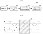
- FIG. 1 is a block diagram of a conventional disconnection detection apparatus
- FIG. 2 is an exemplary diagram for describing a signal output from the detecting apparatus of FIG. 1 .
- an encoder 100 outputs two-phase sinusoidal wave signals (a sine signal and a cosine signal) having a phase difference of 90 degrees to each other, and a disconnection detection apparatus 200 receives the output signals of the encoder 100 to detect whether disconnection of each of the output signals occurs.
- An amplification unit 210 differentially amplifies the output signals of the encoder 100, and a waveform conversion unit 220 converts the differentially amplified sine and cosine wave signals into square wave signals. Also, a disconnection detection unit 230 verifies the square wave signals to detect connection of each thereof.
- 2A is waveforms obtained by differentially amplifying the sine and cosine signals which are the output signals of the sinusoidal wave encoder 100 and represents output signals of the amplification unit 210
- 2B and 2C are waveforms obtained by converting the sine and cosine wave signals which are the output signals of the differential amplification unit 210 into square wave signals and represent output signals of the waveform conversion unit 220.
- 2D is an A-phase square wave converted from the sine wave
- 2E is a B-phase square wave converted from the cosine wave.
- the sinusoidal wave encoder 100 attached to a shaft of an electric motor is a position sensor that outputs a sinusoidal wave corresponding to a position variation of the shaft according to rotation of the electric motor, and the number of output signals per a single rotation of the electric motor is preset so that a variation amount of a rotation position may be obtained through the number of sinusoidal waves being output.
- Each of output signals of the sinusoidal wave encoder 100 has a constant magnitude and a frequency that is varied according to a rotational speed of the electric motor.
- the amplification unit 210 serves to insulate the output signals of the sinusoidal wave encoder 100 and perform a level adjustment of the output signals, and differentially amplifies the output signals such as 2A output from the sinusoidal wave encoder 100 according to a preset gain.
- the waveform conversion unit 220 compares the differentially amplified sine and cosine wave signals from the differential amplification unit 210 with a high signal when the differentially amplified sine and cosine wave signals are greater than zero, or a low signal when they are less than zero to output the A-phase or B-phase square wave signal such as 2B or 2C.
- the disconnection detection unit 230 verifies the A-phase square wave and the B-phase square wave for a predetermined section and detects disconnection when the B-phase square wave does not vary while the A-phase square wave varies.
- the disconnection detection unit 230 may detect disconnection only when variation of a sinusoidal signal occurs for a predetermined time so that there is a problem in that inrush damage to an electric motor may occur while the electric motor operates.
- an object of the present disclosure is to provide a disconnection detection apparatus capable of rapidly detecting disconnection of an encoder signal line based on an output signal of a sinusoidal wave encoder.
- a disconnection detection apparatus of a sinusoidal wave signal may include a first conversion unit configured to convert a first sinusoidal wave and a second sinusoidal wave into absolute values, respectively, and a determination unit configured to determine that disconnection occurs when a value of the first sinusoidal wave is less than a first comparison value that is greater than a minimum value and a value of the second sinusoidal wave is less than a second comparison value that is less than a maximum value.
- the determination unit may determine that the disconnection occurs when the value of the second sinusoidal wave is less than the first comparison value and the value of the first sinusoidal wave is less than the second comparison value.
- the disconnection detection apparatus of one embodiment of the present disclosure may further include an amplification unit configured to differentially amplify the first sinusoidal wave and the second sinusoidal wave which are applied thereto, and a second conversion unit configured to convert the first differentially amplified sinusoidal wave signal and the second differentially amplified sinusoidal wave signal into a first sinusoidal wave and a second sinusoidal wave, respectively, which are digital data.
- an amplification unit configured to differentially amplify the first sinusoidal wave and the second sinusoidal wave which are applied thereto
- a second conversion unit configured to convert the first differentially amplified sinusoidal wave signal and the second differentially amplified sinusoidal wave signal into a first sinusoidal wave and a second sinusoidal wave, respectively, which are digital data.
- the disconnection detection apparatus of one embodiment of the present disclosure may further include an elimination unit configured to eliminate offsets of the first sinusoidal wave and the second sinusoidal wave.
- the determination unit may determine that the disconnection does not occur when the value of the first sinusoidal wave is less than the first comparison value and the value of the second sinusoidal value is greater than the second value and is less than the maximum value.
- the determination unit may determine that the disconnection does not occur when the value of the second sinusoidal wave is less than the first comparison value and the value of the first sinusoidal wave is greater than the second comparison value and is less than the maximum value.
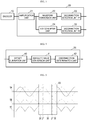
- FIG. 3 is one exemplary diagram for describing a disconnection detection apparatus of a sinusoidal wave signal according to one embodiment of the present disclosure.
- a disconnection detection apparatus 20 of one embodiment of the present disclosure may verify a sinusoidal signal of an encoder 10 and detect disconnection when disconnection of an encoder signal line occurs to transmit the detected disconnection to an upper-level control unit (not shown), thereby stopping an operation of an electric motor.
- the encoder 10 may output two-phase sinusoidal wave signals (a sine signal and a cosine signal) having a phase difference of 90 degrees by the predetermined number when the electric motor rotates a single turn.
- the disconnection detection apparatus 20 of one embodiment of the present disclosure may include an amplification unit 21, a waveform conversion unit 22, a first disconnection detection unit 23, an analog/digital (A/D) converter unit 24, and a second disconnection detection unit 25.
- the amplification unit 21 may differentially amplify a first sinusoidal wave signal sin and a second sinusoidal wave signal cos of the encoder 10.
- the waveform conversion unit 22 may convert the first differentially amplified sinusoidal wave signal sin and the second differentially amplified sinusoidal wave signal cos into square wave signals.
- the first disconnection detection unit 23 may verify the square wave signals converted by the waveform conversion unit 22 to detect disconnection.
- the A/D converter unit 24 may convert the first differentially amplified sinusoidal wave signal sin and the second differentially amplified sinusoidal wave signal cos into digital data, and also the second disconnection detection unit 25 may detect disconnection with respect to the digital data.
- the amplification unit 21 serves to insulate the output signals of the sinusoidal wave encoder 10 and perform a level adjustment of the output signals, and may differentially amplify the signals such as 2A output from the sinusoidal wave encoder 10 according to a preset gain.
- the waveform conversion unit 22 may output the first differentially amplified sinusoidal wave signal sin and the second differentially amplified sinusoidal wave signal cos from the differential amplification unit 21 as a high signal when the first differentially amplified sinusoidal wave signal sin and the second differentially amplified sinusoidal wave signal cos are greater than zero, or as a low signal when they are less than zero, thereby outputting A-phase and B-phase square wave signals such as 2B and 2C.
- the first disconnection detection unit 23 may verify the A-phase square wave and the B-phase square wave for a predetermined section and detect disconnection when the B-phase square wave does not vary while the A-phase square wave varies to transmit the detected disconnection to an upper-level control unit (not shown).
- the A/D converter unit 24 may convert the first sinusoidal wave signal and the second sinusoidal wave signal which are differentially amplified by the amplification unit 21 into digital data.
- FIG. 4 is a detailed block diagram of one embodiment of the second disconnection detection unit of FIG. 3
- FIG. 5 is one exemplary diagram for describing signals being output from the disconnection detection apparatus of the present disclosure
- FIG. 6 is one exemplary diagram for describing a disconnection detection condition based on an output signal from the second disconnection detection unit of FIG. 4 .
- the second disconnection detection unit 25 may include an offset elimination unit 40, an absolute value conversion unit 41, and a disconnection determination unit 42.
- 5A is a waveform obtained by differentially amplifying the first sinusoidal wave signal sin and the second sinusoidal wave signal cos which are output signals of the sinusoidal wave encoder 10, and represents an output signal of the amplification unit 21.
- 5B and 5C are waveforms representing absolute values of the signals of 5A. At this point, 5B may represent the absolute value of the first sinusoidal wave signal sin , and 5C may represent the absolute value of the second sinusoidal wave signal cos.
- 5D is provided to describe a region in which disconnection occurs, and, at this point, 5E represents a region in which a disconnection detection is possible and 5F represents a region in which the disconnection detection is not possible.
- the offset elimination unit 40 may eliminate offsets of the first and second sinusoidal wave signals which are digital data converted by the A/D converter unit 24.
- the absolute value conversion unit 41 may obtain absolute values of the first and second sinusoidal wave signals from which the offsets are eliminated to perform an absolute value process on a wave signal having a value less than zero.
- the disconnection determination unit 42 may determine whether each of the first and second sinusoidal wave signals which are undergone the absolute value process corresponds to a disconnection condition to detect disconnection of a signal, and may provide the detected disconnection to the upper-level control unit (not shown) to stop an operation of the electric motor.
- FIG. 6 is a diagram for describing a disconnection detection condition according to one embodiment of the present disclosure
- 6A and 6B represent a maximum magnitude and a minimum magnitude of the first sinusoidal wave signal sin , respectively.
- 6C and 6D represent a maximum magnitude and a minimum magnitude of the second sinusoidal wave signal cos, respectively.
- 5E represents a section in which a disconnection detection is possible, and a section in which the disconnection detection is not possible is not existed as shown in FIG. 5 in accordance with the present disclosure.
- the disconnection determination unit 42 determines that disconnection does not occur. Further, when the value of the second sinusoidal wave signal cos is less than the second comparison value 6F, the disconnection determination unit 42 may determine that disconnection occurs. This uses a condition in which a value difference at the same phase is less than a difference between the maximum value and the minimum value when absolute values of the first and second sinusoidal wave signals are obtained.
- the first sinusoidal wave signal sin When the value of the first sinusoidal wave signal sin is greater than the first comparison value 6E, the first sinusoidal wave signal sin may be determined as not being disconnected. At this point, the first comparison value 6E may be determined as a value greater than the minimum value of the first or second sinusoidal wave signal, and the second comparison value 6F may be determined as a value less than the maximum value 6G of the first or second sinusoidal wave signal.
- the disconnection determination unit 42 determines that disconnection does not occur.
- the disconnection determination unit 42 determines that disconnection occurs.
- the value of the second sinusoidal wave signal cos is greater than the first comparison value 6E, the second sinusoidal wave signal cos may be determined as not being disconnected.
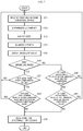
- FIG. 7 is a flow chart for describing a disconnection detection method according to one embodiment of the present disclosure.
- the amplification unit 21 receives the first and second sinusoidal wave signals sin and cos from the sinusoidal wave encoder 10 in Operation S71, and differentially amplifies the received signals in Operation S72. Thereafter, the A/D converter unit 24 may convert the first and second sinusoidal wave signals which are the differentially amplified analog signals into digital data in Operation S73.
- the offset elimination unit 40 of the disconnection determination unit 42 may eliminate offsets of the first and second sinusoidal wave signals which are converted into the digital data in Operation S74, and the absolute value conversion unit 41 may obtain absolute values of the first and second sinusoidal wave signals to convert a portion representing a value less than zero into a corresponding absolute value in Operation S75.
- the disconnection determination unit 42 may determine that disconnection occurs in Operation S79.
- the disconnection determination unit 42 may determine that the disconnection does not occur and it may return.
- the disconnection determination unit 42 may determine that the disconnection occurs in Operation S79.
- the disconnection determination unit 42 may determine that the disconnection does not occur and it may return.
- one embodiment of the present disclosure addresses a problem in that a disconnection determination is conventionally performed after one period is progressed since disconnection occurred so that it is capable of detecting disconnection for a short time prior to a progress of one period of a sinusoidal wave.
- A/D Converter Unit 25 Disconnection detection Unit 40: Offset Elimination Unit 41: Absolute Value Conversion Unit 42: Disconnection Determination Unit
Landscapes
- Engineering & Computer Science (AREA)
- Physics & Mathematics (AREA)
- General Physics & Mathematics (AREA)
- Power Engineering (AREA)
- Theoretical Computer Science (AREA)
- Microelectronics & Electronic Packaging (AREA)
- Transmission And Conversion Of Sensor Element Output (AREA)
- Testing Of Short-Circuits, Discontinuities, Leakage, Or Incorrect Line Connections (AREA)
Abstract
The disconnection detection apparatus (20) of the present disclosure converts the sine and cosine signals into absolute values, respectively, and determines that disconnection occurs when a value of the first sinusoidal wave is less than a first low comparison value that is greater than a minimum value and a value of the second sinusoidal wave is less than a second higher comparison value which is less than the maximum value.
Due to the defined phase shift between the signals one of them has to be close to the maximum when the other is close to the minimum, in case of normal operation.
Description
- The present disclosure relates to a disconnection detection apparatus of a sinusoidal wave signal.
- Generally, a variable speed driving of an alternating current (AC) electric motor through an inverter is widely used, and there is a field requiring for an accurate speed control of an electric motor. In this case, a speed detection sensor is attached to the electric motor to detect a speed thereof.
- An incremental encoder is widely used for such a speed detection sensor. The incremental encoder is roughly classified into an encoder outputting a square wave signal and an encoder outputting a sinusoidal wave signal.
- The encoder for outputting a sinusoidal wave signal (a sinusoidal wave encoder) outputs two-phase sinusoidal waves having a phase difference of 90 degrees to each other by the predetermined number per a single rotation of an electric motor.
- When an output signal of a sinusoidal wave encoder is disconnected, a disconnection detection apparatus, which is generally provided at an inverter, detects the disconnection of the output signal to stop an electric motor.
-
FIG. 1 is a block diagram of a conventional disconnection detection apparatus, andFIG. 2 is an exemplary diagram for describing a signal output from the detecting apparatus ofFIG. 1 . - In the conventional apparatus, an
encoder 100 outputs two-phase sinusoidal wave signals (a sine signal and a cosine signal) having a phase difference of 90 degrees to each other, and adisconnection detection apparatus 200 receives the output signals of theencoder 100 to detect whether disconnection of each of the output signals occurs. - An
amplification unit 210 differentially amplifies the output signals of theencoder 100, and awaveform conversion unit 220 converts the differentially amplified sine and cosine wave signals into square wave signals. Also, adisconnection detection unit 230 verifies the square wave signals to detect connection of each thereof. - In
FIG. 2 , 2A is waveforms obtained by differentially amplifying the sine and cosine signals which are the output signals of thesinusoidal wave encoder 100 and represents output signals of theamplification unit differential amplification unit 210 into square wave signals and represent output signals of thewaveform conversion unit 220. At this point, 2D is an A-phase square wave converted from the sine wave, and 2E is a B-phase square wave converted from the cosine wave. - Firstly, the
sinusoidal wave encoder 100 attached to a shaft of an electric motor (not shown) is a position sensor that outputs a sinusoidal wave corresponding to a position variation of the shaft according to rotation of the electric motor, and the number of output signals per a single rotation of the electric motor is preset so that a variation amount of a rotation position may be obtained through the number of sinusoidal waves being output. - An operation of the conventional
disconnection detection apparatus 200 will be described. - Each of output signals of the
sinusoidal wave encoder 100 has a constant magnitude and a frequency that is varied according to a rotational speed of the electric motor. Theamplification unit 210 serves to insulate the output signals of thesinusoidal wave encoder 100 and perform a level adjustment of the output signals, and differentially amplifies the output signals such as 2A output from thesinusoidal wave encoder 100 according to a preset gain. - The
waveform conversion unit 220 compares the differentially amplified sine and cosine wave signals from thedifferential amplification unit 210 with a high signal when the differentially amplified sine and cosine wave signals are greater than zero, or a low signal when they are less than zero to output the A-phase or B-phase square wave signal such as 2B or 2C. - When a cosine wave signal of the output signals of the
sinusoidal wave encoder 100 is disconnected as shown in aregion 2F ofFIG. 2 , thedisconnection detection unit 230 verifies the A-phase square wave and the B-phase square wave for a predetermined section and detects disconnection when the B-phase square wave does not vary while the A-phase square wave varies. - However, the
disconnection detection unit 230 may detect disconnection only when variation of a sinusoidal signal occurs for a predetermined time so that there is a problem in that inrush damage to an electric motor may occur while the electric motor operates. - To address the problem described above, an object of the present disclosure is to provide a disconnection detection apparatus capable of rapidly detecting disconnection of an encoder signal line based on an output signal of a sinusoidal wave encoder.
- To attain the above described object, a disconnection detection apparatus of a sinusoidal wave signal may include a first conversion unit configured to convert a first sinusoidal wave and a second sinusoidal wave into absolute values, respectively, and a determination unit configured to determine that disconnection occurs when a value of the first sinusoidal wave is less than a first comparison value that is greater than a minimum value and a value of the second sinusoidal wave is less than a second comparison value that is less than a maximum value.
- In one embodiment of the present disclosure, the determination unit may determine that the disconnection occurs when the value of the second sinusoidal wave is less than the first comparison value and the value of the first sinusoidal wave is less than the second comparison value.
- The disconnection detection apparatus of one embodiment of the present disclosure may further include an amplification unit configured to differentially amplify the first sinusoidal wave and the second sinusoidal wave which are applied thereto, and a second conversion unit configured to convert the first differentially amplified sinusoidal wave signal and the second differentially amplified sinusoidal wave signal into a first sinusoidal wave and a second sinusoidal wave, respectively, which are digital data.
- The disconnection detection apparatus of one embodiment of the present disclosure may further include an elimination unit configured to eliminate offsets of the first sinusoidal wave and the second sinusoidal wave.
- In one embodiment of the present disclosure, the determination unit may determine that the disconnection does not occur when the value of the first sinusoidal wave is less than the first comparison value and the value of the second sinusoidal value is greater than the second value and is less than the maximum value.
- In one embodiment of the present disclosure, the determination unit may determine that the disconnection does not occur when the value of the second sinusoidal wave is less than the first comparison value and the value of the first sinusoidal wave is greater than the second comparison value and is less than the maximum value.
- As described above, in accordance with the present disclosure, there is an effect in which disconnection may be detected in a short time prior to a progress of one period of a sinusoidal wave.
-
-
FIG. 1 is a block diagram of a conventional disconnection detection apparatus. -
FIG. 2 is an exemplary diagram for describing signals being output from the disconnection detection apparatus ofFIG. 1 . -
FIG. 3 is one exemplary diagram for describing a disconnection detection apparatus of a sinusoidal wave signal according to one embodiment of the present disclosure. -
FIG. 4 is a detailed block diagram of one embodiment of a second disconnection detection unit ofFIG. 3 . -
FIG. 5 is one exemplary diagram for describing signals being output from the disconnection detection apparatus of the present disclosure. -
FIG. 6 is one exemplary diagram for describing a disconnection detection condition based on an output signal from the second disconnection detection unit ofFIG. 4 . -
FIG. 7 is a flow chart for describing a disconnection detection method according to one embodiment of the present disclosure. - The present disclosure may be variously modified and will have a variety of embodiments so that specific embodiments will be exemplified in the drawings and will be described in detail. The specific embodiments disclosed herein, however, are not to be taken in a sense for limiting the present disclosure to these embodiments, but for explanation thereof and it should be understood that numerous other alternations, equivalents and substituents will be falling within the spirit and scope of the present disclosure.
- Hereinafter, one preferred embodiment according to the present disclosure will be described in detail with reference to the accompanying drawings.
-
FIG. 3 is one exemplary diagram for describing a disconnection detection apparatus of a sinusoidal wave signal according to one embodiment of the present disclosure. - As shown in the drawing, a
disconnection detection apparatus 20 of one embodiment of the present disclosure may verify a sinusoidal signal of anencoder 10 and detect disconnection when disconnection of an encoder signal line occurs to transmit the detected disconnection to an upper-level control unit (not shown), thereby stopping an operation of an electric motor. - The
encoder 10 may output two-phase sinusoidal wave signals (a sine signal and a cosine signal) having a phase difference of 90 degrees by the predetermined number when the electric motor rotates a single turn. - The
disconnection detection apparatus 20 of one embodiment of the present disclosure may include anamplification unit 21, awaveform conversion unit 22, a firstdisconnection detection unit 23, an analog/digital (A/D)converter unit 24, and a seconddisconnection detection unit 25. - The
amplification unit 21 may differentially amplify a first sinusoidal wave signal sin and a second sinusoidal wave signal cos of theencoder 10. Thewaveform conversion unit 22 may convert the first differentially amplified sinusoidal wave signal sin and the second differentially amplified sinusoidal wave signal cos into square wave signals. Also, the firstdisconnection detection unit 23 may verify the square wave signals converted by thewaveform conversion unit 22 to detect disconnection. - The A/
D converter unit 24 may convert the first differentially amplified sinusoidal wave signal sin and the second differentially amplified sinusoidal wave signal cos into digital data, and also the seconddisconnection detection unit 25 may detect disconnection with respect to the digital data. - Operations of the
amplification unit 21, thewaveform conversion unit 22, and the firstdisconnection detection unit 23 will be described with reference toFIG. 2 . - The
amplification unit 21 serves to insulate the output signals of thesinusoidal wave encoder 10 and perform a level adjustment of the output signals, and may differentially amplify the signals such as 2A output from thesinusoidal wave encoder 10 according to a preset gain. - The
waveform conversion unit 22 may output the first differentially amplified sinusoidal wave signal sin and the second differentially amplified sinusoidal wave signal cos from thedifferential amplification unit 21 as a high signal when the first differentially amplified sinusoidal wave signal sin and the second differentially amplified sinusoidal wave signal cos are greater than zero, or as a low signal when they are less than zero, thereby outputting A-phase and B-phase square wave signals such as 2B and 2C. - When the second sinusoidal wave signal cos of the output signals of the
sinusoidal wave encoder 10 is disconnected as shown in theregion 2F ofFIG. 2 , the firstdisconnection detection unit 23 may verify the A-phase square wave and the B-phase square wave for a predetermined section and detect disconnection when the B-phase square wave does not vary while the A-phase square wave varies to transmit the detected disconnection to an upper-level control unit (not shown). - Meanwhile, operations of the
amplification unit 21, the A/D converter unit 24, and the seconddisconnection detection unit 25 will be described below with reference to the drawing. - The A/
D converter unit 24 may convert the first sinusoidal wave signal and the second sinusoidal wave signal which are differentially amplified by theamplification unit 21 into digital data. -
FIG. 4 is a detailed block diagram of one embodiment of the second disconnection detection unit ofFIG. 3, FIG. 5 is one exemplary diagram for describing signals being output from the disconnection detection apparatus of the present disclosure, andFIG. 6 is one exemplary diagram for describing a disconnection detection condition based on an output signal from the second disconnection detection unit ofFIG. 4 . - As shown in the drawing, in the
disconnection detection apparatus 20 of the present disclosure, the seconddisconnection detection unit 25 may include anoffset elimination unit 40, an absolutevalue conversion unit 41, and adisconnection determination unit 42. - In
FIG. 5, 5A is a waveform obtained by differentially amplifying the first sinusoidal wave signal sin and the second sinusoidal wave signal cos which are output signals of thesinusoidal wave encoder 10, and represents an output signal of theamplification unit 21. 5B and 5C are waveforms representing absolute values of the signals of 5A. At this point, 5B may represent the absolute value of the first sinusoidal wave signal sin, and 5C may represent the absolute value of the second sinusoidal wave signal cos. Also, inFIG. 5, 5D is provided to describe a region in which disconnection occurs, and, at this point, 5E represents a region in which a disconnection detection is possible and 5F represents a region in which the disconnection detection is not possible. - The offset
elimination unit 40 may eliminate offsets of the first and second sinusoidal wave signals which are digital data converted by the A/D converter unit 24. - The absolute
value conversion unit 41 may obtain absolute values of the first and second sinusoidal wave signals from which the offsets are eliminated to perform an absolute value process on a wave signal having a value less than zero. - The
disconnection determination unit 42 may determine whether each of the first and second sinusoidal wave signals which are undergone the absolute value process corresponds to a disconnection condition to detect disconnection of a signal, and may provide the detected disconnection to the upper-level control unit (not shown) to stop an operation of the electric motor. -
FIG. 6 is a diagram for describing a disconnection detection condition according to one embodiment of the present disclosure, and 6A and 6B represent a maximum magnitude and a minimum magnitude of the first sinusoidal wave signal sin, respectively. Further, 6C and 6D represent a maximum magnitude and a minimum magnitude of the second sinusoidal wave signal cos, respectively. - As described in
FIG. 5, 5E represents a section in which a disconnection detection is possible, and a section in which the disconnection detection is not possible is not existed as shown inFIG. 5 in accordance with the present disclosure. - To describe the operation of the
disconnection determination unit 42 again, with respect to the first sinusoidal wave signal sin of the output signals of the absolutevalue conversion unit 41, when a value of the first sinusoidal wave signal sin is less than afirst comparison value 6E, and a value of the second sinusoidal wave signal cos is less than amaximum value 6G and is greater than asecond comparison value 6F, thedisconnection determination unit 42 determines that disconnection does not occur. Further, when the value of the second sinusoidal wave signal cos is less than thesecond comparison value 6F, thedisconnection determination unit 42 may determine that disconnection occurs. This uses a condition in which a value difference at the same phase is less than a difference between the maximum value and the minimum value when absolute values of the first and second sinusoidal wave signals are obtained. - When the value of the first sinusoidal wave signal sin is greater than the
first comparison value 6E, the first sinusoidal wave signal sin may be determined as not being disconnected. At this point, thefirst comparison value 6E may be determined as a value greater than the minimum value of the first or second sinusoidal wave signal, and thesecond comparison value 6F may be determined as a value less than themaximum value 6G of the first or second sinusoidal wave signal. - With respect to the second sinusoidal wave signal cos of the output signals of the absolute
value conversion unit 41, when the value of the second sinusoidal wave signal cos is less than thefirst comparison value 6E, and the value of the first sinusoidal wave signal sin is less than themaximum value 6G and is greater than thesecond comparison value 6F, thedisconnection determination unit 42 determines that disconnection does not occur. - When the value of the first sinusoidal wave signal sin is less than the
second comparison value 6F, thedisconnection determination unit 42 determines that disconnection occurs. On the other hand, when the value of the second sinusoidal wave signal cos is greater than thefirst comparison value 6E, the second sinusoidal wave signal cos may be determined as not being disconnected. -
FIG. 7 is a flow chart for describing a disconnection detection method according to one embodiment of the present disclosure. - With reference to
FIG. 7 , operations of theamplification unit 21, the A/D converter unit 24, and the seconddisconnection detection unit 25 ofFIG. 3 will be described. - As shown in the drawing, in one embodiment of the present disclosure, the
amplification unit 21 receives the first and second sinusoidal wave signals sin and cos from thesinusoidal wave encoder 10 in Operation S71, and differentially amplifies the received signals in Operation S72. Thereafter, the A/D converter unit 24 may convert the first and second sinusoidal wave signals which are the differentially amplified analog signals into digital data in Operation S73. - The offset
elimination unit 40 of thedisconnection determination unit 42 may eliminate offsets of the first and second sinusoidal wave signals which are converted into the digital data in Operation S74, and the absolutevalue conversion unit 41 may obtain absolute values of the first and second sinusoidal wave signals to convert a portion representing a value less than zero into a corresponding absolute value in Operation S75. - When the received data is the first sinusoidal wave signal sin in Operation S 76, a value of the first sinusoidal wave signal sin is less than a
first comparison value 6E in Operation S77, and a value of the second sinusoidal wave signal cos is less that asecond comparison value 6F in Operation S78, thedisconnection determination unit 42 may determine that disconnection occurs in Operation S79. At this point, even though the value of the first sinusoidal wave signal sin is greater than thefirst comparison value 6E in Operation S77 or is less than thefirst comparison value 6E in Operation S77, when the value of the second sinusoidal wave signal cos is less than amaximum value 6G and is greater than asecond comparison value 6F in Operation S78, thedisconnection determination unit 42 may determine that the disconnection does not occur and it may return. - Also, when the received data is the second sinusoidal wave signal cos in Operation S76, a value of the second sinusoidal wave signal cos is less than the
first comparison value 6E in Operation S80, and the value of the first sinusoidal wave signal sin is less than thesecond comparison value 6F in Operation S81, thedisconnection determination unit 42 may determine that the disconnection occurs in Operation S79. At this point, even though the value of the second sinusoidal wave signal cos is greater than thefirst comparison value 6E in Operation S80 or is less than thefirst comparison value 6E in Operation S80, when the value of the second sinusoidal wave signal cos is less than themaximum value 6G and is greater than thesecond comparison value 6F in Operation S81, thedisconnection determination unit 42 may determine that the disconnection does not occur and it may return. - As described above, one embodiment of the present disclosure addresses a problem in that a disconnection determination is conventionally performed after one period is progressed since disconnection occurred so that it is capable of detecting disconnection for a short time prior to a progress of one period of a sinusoidal wave.
- Meanwhile, an example for detecting disconnection with respect to, for example, a sinusoidal wave output from an encoder for detecting a speed of an electric motor has been described herein, but the present disclosure is not limited thereto, and it may be used in detecting disconnection with respect to a sinusoidal wave being output from an apparatus that various sinusoidal waves.
- The present disclosure has been described with reference to the embodiments shown in the drawings, but is merely an illustration, and it should be understood that numerous other modifications and equivalent other embodiments can be devised by those skilled in the art. Therefore, the technical scope of the present invention should be defined by the appended claims.
-
24: A/D Converter Unit 25: Disconnection detection Unit 40: Offset Elimination Unit 41: Absolute Value Conversion Unit 42: Disconnection Determination Unit
Claims (7)
- A disconnection detection apparatus (20) for determining disconnection, comprising:a first conversion unit configured to convert a first sinusoidal wave and a second sinusoidal wave into absolute values, respectively; anda determination unit configured to determine that disconnection occurs when a value of the first sinusoidal wave is less than a first comparison value that is greater than a minimum value and a value of the second sinusoidal wave is less than a second comparison value that is less than a maximum value.
- The disconnection detection apparatus of claim 1, wherein the determination unit determines that the disconnection occurs when the value of the second sinusoidal wave is less than the first comparison value and the value of the first sinusoidal wave is less than the second comparison value.
- The disconnection detection apparatus of claim 1, further comprising:an amplification unit configured to differentially amplify the first sinusoidal wave and the second sinusoidal wave which are applied thereto; anda second conversion unit configured to convert the first differentially amplified sinusoidal wave signal and the second differentially amplified sinusoidal wave signal into a first sinusoidal wave and a second sinusoidal wave which are digital data.
- The disconnection detection apparatus of claim 3, further comprising:an elimination unit configured to eliminate offsets of the first sinusoidal wave and the second sinusoidal wave.
- The disconnection detection apparatus of claim 1, wherein the determination unit determines that the disconnection does not occur when the value of the first sinusoidal wave is less than the first comparison value and the value of the second sinusoidal value is greater than the second value and is less than the maximum value.
- The disconnection detection apparatus of claim 2, wherein the determination unit determines that the disconnection does not occur when the value of the second sinusoidal wave is less than the first comparison value and the value of the first sinusoidal wave is greater than the second comparison value and is less than the maximum value.
- The disconnection detection apparatus of claim 1, wherein the second sinusoidal wave has a phase difference of 90 degrees with respect to the first sinusoidal wave.
Applications Claiming Priority (1)
| Application Number | Priority Date | Filing Date | Title |
|---|---|---|---|
| KR1020160050336A KR101773334B1 (en) | 2016-04-25 | 2016-04-25 | Apparatus for detecting signal wire open |
Publications (2)
| Publication Number | Publication Date |
|---|---|
| EP3239725A1 true EP3239725A1 (en) | 2017-11-01 |
| EP3239725B1 EP3239725B1 (en) | 2024-06-05 |
Family
ID=57471660
Family Applications (1)
| Application Number | Title | Priority Date | Filing Date |
|---|---|---|---|
| EP16201184.5A Active EP3239725B1 (en) | 2016-04-25 | 2016-11-29 | Disconnection detection apparatus of sinusoidal wave signal |
Country Status (5)
| Country | Link |
|---|---|
| US (1) | US10312836B2 (en) |
| EP (1) | EP3239725B1 (en) |
| JP (2) | JP2017198648A (en) |
| KR (1) | KR101773334B1 (en) |
| CN (1) | CN107306136B (en) |
Families Citing this family (1)
| Publication number | Priority date | Publication date | Assignee | Title |
|---|---|---|---|---|
| US20230339331A1 (en) * | 2020-10-30 | 2023-10-26 | Mitsubishi Electric Corporation | Failure determination device, drive control device, and failure determination method |
Citations (3)
| Publication number | Priority date | Publication date | Assignee | Title |
|---|---|---|---|---|
| JP2012098195A (en) * | 2010-11-04 | 2012-05-24 | Denso Corp | Abnormality diagnostic device in rotation angle detection system |
| US20150247746A1 (en) * | 2012-11-14 | 2015-09-03 | Baumueller Nuernberg Gmbh | Method for calibrating a rotary encoder |
| US20150263659A1 (en) * | 2014-03-13 | 2015-09-17 | Lsis Co., Ltd. | Apparatus for detecting speed of motor |
Family Cites Families (22)
| Publication number | Priority date | Publication date | Assignee | Title |
|---|---|---|---|---|
| JPS5714516Y2 (en) * | 1975-10-17 | 1982-03-25 | ||
| JPH0580846A (en) | 1991-09-25 | 1993-04-02 | Matsushita Electric Ind Co Ltd | Open circuit detecting means |
| JP3442316B2 (en) * | 1999-06-11 | 2003-09-02 | 多摩川精機株式会社 | How to convert analog signals to digital |
| JP2001249154A (en) * | 2000-03-03 | 2001-09-14 | Yaskawa Electric Corp | Encoder disconnection detection device and disconnection detection method |
| JP4155465B2 (en) * | 2004-04-23 | 2008-09-24 | 株式会社日立製作所 | Resolver / digital converter |
| JP2005335913A (en) * | 2004-05-28 | 2005-12-08 | Mitsubishi Electric Corp | Elevator equipment |
| JP2006234688A (en) * | 2005-02-25 | 2006-09-07 | Victor Co Of Japan Ltd | Rotation angle detector and rotation angle controlling device for motor |
| KR20070039244A (en) | 2005-10-07 | 2007-04-11 | 두산인프라코어 주식회사 | Encoder error detection device |
| CN100533900C (en) * | 2007-08-16 | 2009-08-26 | 浙江大学 | Electric network state detecting method used for creepage protector |
| JP5028294B2 (en) * | 2008-02-14 | 2012-09-19 | 日立オートモティブシステムズ株式会社 | Resolver abnormality detection device |
| JP2010014410A (en) | 2008-07-01 | 2010-01-21 | Meidensha Corp | Rotational position detecting apparatus of rotator |
| JP5310107B2 (en) * | 2009-02-09 | 2013-10-09 | 富士電機株式会社 | Abnormality monitoring device |
| JP5789911B2 (en) * | 2009-10-06 | 2015-10-07 | 株式会社ジェイテクト | Rotation angle detection device and electric power steering device |
| CN101777747A (en) * | 2010-01-29 | 2010-07-14 | 浙江大学 | Power grid state detection method of leakage protector with light coupling isolation |
| KR20130029195A (en) * | 2011-09-14 | 2013-03-22 | 현대모비스 주식회사 | Resolver failure detecting system for motor of vehicle |
| CN103001310B (en) * | 2012-11-23 | 2014-09-17 | 成都科星电器桥架有限公司 | Photovoltaic power generation and urban power grid parallel power supply switching device |
| JP6013963B2 (en) * | 2013-03-29 | 2016-10-25 | 日立オートモティブシステムズ株式会社 | Diagnostic equipment |
| KR101500143B1 (en) * | 2013-09-16 | 2015-03-18 | 현대자동차주식회사 | Fault detection interface circuit of a resolver and method thereof |
| KR101646346B1 (en) * | 2014-09-23 | 2016-08-05 | 현대자동차주식회사 | Apparatus and method for controlling motor |
| CN204666756U (en) * | 2015-03-12 | 2015-09-23 | 深圳市海浦蒙特科技有限公司 | Sine and cosine encoder broken wire detection system |
| CN104749481A (en) * | 2015-03-12 | 2015-07-01 | 深圳市海浦蒙特科技有限公司 | Sine and cosine encoder offline detection method and system |
| CN104777397B (en) * | 2015-04-16 | 2017-09-22 | 王金泽 | Distribution line single-phase wire break based on the vectorial criterion of line voltage judges and localization method |
-
2016
- 2016-04-25 KR KR1020160050336A patent/KR101773334B1/en active Active
- 2016-11-29 EP EP16201184.5A patent/EP3239725B1/en active Active
- 2016-11-29 CN CN201611073774.2A patent/CN107306136B/en active Active
- 2016-12-02 JP JP2016235319A patent/JP2017198648A/en active Pending
- 2016-12-20 US US15/384,809 patent/US10312836B2/en active Active
-
2018
- 2018-11-19 JP JP2018216757A patent/JP6743110B2/en active Active
Patent Citations (3)
| Publication number | Priority date | Publication date | Assignee | Title |
|---|---|---|---|---|
| JP2012098195A (en) * | 2010-11-04 | 2012-05-24 | Denso Corp | Abnormality diagnostic device in rotation angle detection system |
| US20150247746A1 (en) * | 2012-11-14 | 2015-09-03 | Baumueller Nuernberg Gmbh | Method for calibrating a rotary encoder |
| US20150263659A1 (en) * | 2014-03-13 | 2015-09-17 | Lsis Co., Ltd. | Apparatus for detecting speed of motor |
Also Published As
| Publication number | Publication date |
|---|---|
| JP2017198648A (en) | 2017-11-02 |
| EP3239725B1 (en) | 2024-06-05 |
| JP2019053082A (en) | 2019-04-04 |
| JP6743110B2 (en) | 2020-08-19 |
| CN107306136B (en) | 2021-07-13 |
| US20170310250A1 (en) | 2017-10-26 |
| CN107306136A (en) | 2017-10-31 |
| KR101773334B1 (en) | 2017-09-12 |
| US10312836B2 (en) | 2019-06-04 |
Similar Documents
| Publication | Publication Date | Title |
|---|---|---|
| JP6575582B2 (en) | POSITION ESTIMATION METHOD AND POSITION CONTROL DEVICE | |
| US7513169B2 (en) | Rotational position measuring device | |
| US10408643B2 (en) | Methods and apparatus to increase resolver-to-digital converter accuracy | |
| EP1589323A2 (en) | Resolver digital converter | |
| KR101540176B1 (en) | Apparatus for detecting speed of moror | |
| JP5082642B2 (en) | Resolver / digital conversion method and resolver / digital conversion circuit | |
| EP2108924B1 (en) | Position detecting device and method | |
| EP3239725B1 (en) | Disconnection detection apparatus of sinusoidal wave signal | |
| US9528857B2 (en) | Time capture based resolver to digital converter | |
| KR20210071532A (en) | Programmed Automatical Calibration Method for an Initial Rotary Offset of a Rotor Position Sensor of a Motor and a Motor Having a Controller Programmed According to the Same | |
| CN107561398B (en) | Sin-Cos Encoder Disconnection Fault Detection Method and Device | |
| JP6848222B2 (en) | Speed sensor interface circuit | |
| JP2009300222A (en) | Device for detecting abnormal condition in angular displacement sensor | |
| CN101662226A (en) | Inverter Gain Synchronization Device | |
| KR102492602B1 (en) | Method and apparatus for detecting resolver error | |
| US10394217B2 (en) | Motor driving apparatus | |
| JP5429575B2 (en) | Resolver signal processing device | |
| KR101893390B1 (en) | Inspection method for ad converter using rotation coordinate system conversion | |
| JP2615623B2 (en) | Position detector disconnection detection circuit | |
| JP2004286591A (en) | Displacement measuring device |
Legal Events
| Date | Code | Title | Description |
|---|---|---|---|
| PUAI | Public reference made under article 153(3) epc to a published international application that has entered the european phase |
Free format text: ORIGINAL CODE: 0009012 |
|
| STAA | Information on the status of an ep patent application or granted ep patent |
Free format text: STATUS: THE APPLICATION HAS BEEN PUBLISHED |
|
| AK | Designated contracting states |
Kind code of ref document: A1 Designated state(s): AL AT BE BG CH CY CZ DE DK EE ES FI FR GB GR HR HU IE IS IT LI LT LU LV MC MK MT NL NO PL PT RO RS SE SI SK SM TR |
|
| AX | Request for extension of the european patent |
Extension state: BA ME |
|
| STAA | Information on the status of an ep patent application or granted ep patent |
Free format text: STATUS: REQUEST FOR EXAMINATION WAS MADE |
|
| 17P | Request for examination filed |
Effective date: 20180419 |
|
| RBV | Designated contracting states (corrected) |
Designated state(s): AL AT BE BG CH CY CZ DE DK EE ES FI FR GB GR HR HU IE IS IT LI LT LU LV MC MK MT NL NO PL PT RO RS SE SI SK SM TR |
|
| STAA | Information on the status of an ep patent application or granted ep patent |
Free format text: STATUS: EXAMINATION IS IN PROGRESS |
|
| 17Q | First examination report despatched |
Effective date: 20190814 |
|
| GRAP | Despatch of communication of intention to grant a patent |
Free format text: ORIGINAL CODE: EPIDOSNIGR1 |
|
| STAA | Information on the status of an ep patent application or granted ep patent |
Free format text: STATUS: GRANT OF PATENT IS INTENDED |
|
| RIC1 | Information provided on ipc code assigned before grant |
Ipc: G01D 5/244 20060101ALN20240125BHEP Ipc: G01P 21/02 20060101AFI20240125BHEP |
|
| INTG | Intention to grant announced |
Effective date: 20240206 |
|
| GRAS | Grant fee paid |
Free format text: ORIGINAL CODE: EPIDOSNIGR3 |
|
| GRAA | (expected) grant |
Free format text: ORIGINAL CODE: 0009210 |
|
| STAA | Information on the status of an ep patent application or granted ep patent |
Free format text: STATUS: THE PATENT HAS BEEN GRANTED |
|
| AK | Designated contracting states |
Kind code of ref document: B1 Designated state(s): AL AT BE BG CH CY CZ DE DK EE ES FI FR GB GR HR HU IE IS IT LI LT LU LV MC MK MT NL NO PL PT RO RS SE SI SK SM TR |
|
| REG | Reference to a national code |
Ref country code: GB Ref legal event code: FG4D |
|
| REG | Reference to a national code |
Ref country code: CH Ref legal event code: EP |
|
| REG | Reference to a national code |
Ref country code: DE Ref legal event code: R096 Ref document number: 602016087823 Country of ref document: DE |
|
| REG | Reference to a national code |
Ref country code: IE Ref legal event code: FG4D |
|
| P01 | Opt-out of the competence of the unified patent court (upc) registered |
Free format text: CASE NUMBER: APP_42820/2024 Effective date: 20240721 |
|
| REG | Reference to a national code |
Ref country code: LT Ref legal event code: MG9D |
|
| PG25 | Lapsed in a contracting state [announced via postgrant information from national office to epo] |
Ref country code: BG Free format text: LAPSE BECAUSE OF FAILURE TO SUBMIT A TRANSLATION OF THE DESCRIPTION OR TO PAY THE FEE WITHIN THE PRESCRIBED TIME-LIMIT Effective date: 20240605 |
|
| REG | Reference to a national code |
Ref country code: NL Ref legal event code: MP Effective date: 20240605 |
|
| PG25 | Lapsed in a contracting state [announced via postgrant information from national office to epo] |
Ref country code: FI Free format text: LAPSE BECAUSE OF FAILURE TO SUBMIT A TRANSLATION OF THE DESCRIPTION OR TO PAY THE FEE WITHIN THE PRESCRIBED TIME-LIMIT Effective date: 20240605 Ref country code: HR Free format text: LAPSE BECAUSE OF FAILURE TO SUBMIT A TRANSLATION OF THE DESCRIPTION OR TO PAY THE FEE WITHIN THE PRESCRIBED TIME-LIMIT Effective date: 20240605 |
|
| PG25 | Lapsed in a contracting state [announced via postgrant information from national office to epo] |
Ref country code: GR Free format text: LAPSE BECAUSE OF FAILURE TO SUBMIT A TRANSLATION OF THE DESCRIPTION OR TO PAY THE FEE WITHIN THE PRESCRIBED TIME-LIMIT Effective date: 20240906 |
|
| PG25 | Lapsed in a contracting state [announced via postgrant information from national office to epo] |
Ref country code: ES Free format text: LAPSE BECAUSE OF FAILURE TO SUBMIT A TRANSLATION OF THE DESCRIPTION OR TO PAY THE FEE WITHIN THE PRESCRIBED TIME-LIMIT Effective date: 20240605 |
|
| PG25 | Lapsed in a contracting state [announced via postgrant information from national office to epo] |
Ref country code: LV Free format text: LAPSE BECAUSE OF FAILURE TO SUBMIT A TRANSLATION OF THE DESCRIPTION OR TO PAY THE FEE WITHIN THE PRESCRIBED TIME-LIMIT Effective date: 20240605 |
|
| PG25 | Lapsed in a contracting state [announced via postgrant information from national office to epo] |
Ref country code: NO Free format text: LAPSE BECAUSE OF FAILURE TO SUBMIT A TRANSLATION OF THE DESCRIPTION OR TO PAY THE FEE WITHIN THE PRESCRIBED TIME-LIMIT Effective date: 20240905 Ref country code: LV Free format text: LAPSE BECAUSE OF FAILURE TO SUBMIT A TRANSLATION OF THE DESCRIPTION OR TO PAY THE FEE WITHIN THE PRESCRIBED TIME-LIMIT Effective date: 20240605 Ref country code: HR Free format text: LAPSE BECAUSE OF FAILURE TO SUBMIT A TRANSLATION OF THE DESCRIPTION OR TO PAY THE FEE WITHIN THE PRESCRIBED TIME-LIMIT Effective date: 20240605 Ref country code: GR Free format text: LAPSE BECAUSE OF FAILURE TO SUBMIT A TRANSLATION OF THE DESCRIPTION OR TO PAY THE FEE WITHIN THE PRESCRIBED TIME-LIMIT Effective date: 20240906 Ref country code: FI Free format text: LAPSE BECAUSE OF FAILURE TO SUBMIT A TRANSLATION OF THE DESCRIPTION OR TO PAY THE FEE WITHIN THE PRESCRIBED TIME-LIMIT Effective date: 20240605 Ref country code: ES Free format text: LAPSE BECAUSE OF FAILURE TO SUBMIT A TRANSLATION OF THE DESCRIPTION OR TO PAY THE FEE WITHIN THE PRESCRIBED TIME-LIMIT Effective date: 20240605 Ref country code: BG Free format text: LAPSE BECAUSE OF FAILURE TO SUBMIT A TRANSLATION OF THE DESCRIPTION OR TO PAY THE FEE WITHIN THE PRESCRIBED TIME-LIMIT Effective date: 20240605 Ref country code: RS Free format text: LAPSE BECAUSE OF FAILURE TO SUBMIT A TRANSLATION OF THE DESCRIPTION OR TO PAY THE FEE WITHIN THE PRESCRIBED TIME-LIMIT Effective date: 20240905 |
|
| PG25 | Lapsed in a contracting state [announced via postgrant information from national office to epo] |
Ref country code: NL Free format text: LAPSE BECAUSE OF FAILURE TO SUBMIT A TRANSLATION OF THE DESCRIPTION OR TO PAY THE FEE WITHIN THE PRESCRIBED TIME-LIMIT Effective date: 20240605 |
|
| REG | Reference to a national code |
Ref country code: AT Ref legal event code: MK05 Ref document number: 1692824 Country of ref document: AT Kind code of ref document: T Effective date: 20240605 |
|
| PG25 | Lapsed in a contracting state [announced via postgrant information from national office to epo] |
Ref country code: NL Free format text: LAPSE BECAUSE OF FAILURE TO SUBMIT A TRANSLATION OF THE DESCRIPTION OR TO PAY THE FEE WITHIN THE PRESCRIBED TIME-LIMIT Effective date: 20240605 |
|
| PG25 | Lapsed in a contracting state [announced via postgrant information from national office to epo] |
Ref country code: PT Free format text: LAPSE BECAUSE OF FAILURE TO SUBMIT A TRANSLATION OF THE DESCRIPTION OR TO PAY THE FEE WITHIN THE PRESCRIBED TIME-LIMIT Effective date: 20241007 |
|
| PG25 | Lapsed in a contracting state [announced via postgrant information from national office to epo] |
Ref country code: PT Free format text: LAPSE BECAUSE OF FAILURE TO SUBMIT A TRANSLATION OF THE DESCRIPTION OR TO PAY THE FEE WITHIN THE PRESCRIBED TIME-LIMIT Effective date: 20241007 |
|
| PG25 | Lapsed in a contracting state [announced via postgrant information from national office to epo] |
Ref country code: PL Free format text: LAPSE BECAUSE OF FAILURE TO SUBMIT A TRANSLATION OF THE DESCRIPTION OR TO PAY THE FEE WITHIN THE PRESCRIBED TIME-LIMIT Effective date: 20240605 |
|
| PG25 | Lapsed in a contracting state [announced via postgrant information from national office to epo] |
Ref country code: EE Free format text: LAPSE BECAUSE OF FAILURE TO SUBMIT A TRANSLATION OF THE DESCRIPTION OR TO PAY THE FEE WITHIN THE PRESCRIBED TIME-LIMIT Effective date: 20240605 |
|
| PG25 | Lapsed in a contracting state [announced via postgrant information from national office to epo] |
Ref country code: IS Free format text: LAPSE BECAUSE OF FAILURE TO SUBMIT A TRANSLATION OF THE DESCRIPTION OR TO PAY THE FEE WITHIN THE PRESCRIBED TIME-LIMIT Effective date: 20241005 Ref country code: AT Free format text: LAPSE BECAUSE OF FAILURE TO SUBMIT A TRANSLATION OF THE DESCRIPTION OR TO PAY THE FEE WITHIN THE PRESCRIBED TIME-LIMIT Effective date: 20240605 |
|
| PG25 | Lapsed in a contracting state [announced via postgrant information from national office to epo] |
Ref country code: CZ Free format text: LAPSE BECAUSE OF FAILURE TO SUBMIT A TRANSLATION OF THE DESCRIPTION OR TO PAY THE FEE WITHIN THE PRESCRIBED TIME-LIMIT Effective date: 20240605 |
|
| PG25 | Lapsed in a contracting state [announced via postgrant information from national office to epo] |
Ref country code: RO Free format text: LAPSE BECAUSE OF FAILURE TO SUBMIT A TRANSLATION OF THE DESCRIPTION OR TO PAY THE FEE WITHIN THE PRESCRIBED TIME-LIMIT Effective date: 20240605 Ref country code: SK Free format text: LAPSE BECAUSE OF FAILURE TO SUBMIT A TRANSLATION OF THE DESCRIPTION OR TO PAY THE FEE WITHIN THE PRESCRIBED TIME-LIMIT Effective date: 20240605 |
|
| PG25 | Lapsed in a contracting state [announced via postgrant information from national office to epo] |
Ref country code: SM Free format text: LAPSE BECAUSE OF FAILURE TO SUBMIT A TRANSLATION OF THE DESCRIPTION OR TO PAY THE FEE WITHIN THE PRESCRIBED TIME-LIMIT Effective date: 20240605 |
|
| PG25 | Lapsed in a contracting state [announced via postgrant information from national office to epo] |
Ref country code: SM Free format text: LAPSE BECAUSE OF FAILURE TO SUBMIT A TRANSLATION OF THE DESCRIPTION OR TO PAY THE FEE WITHIN THE PRESCRIBED TIME-LIMIT Effective date: 20240605 Ref country code: SK Free format text: LAPSE BECAUSE OF FAILURE TO SUBMIT A TRANSLATION OF THE DESCRIPTION OR TO PAY THE FEE WITHIN THE PRESCRIBED TIME-LIMIT Effective date: 20240605 Ref country code: RO Free format text: LAPSE BECAUSE OF FAILURE TO SUBMIT A TRANSLATION OF THE DESCRIPTION OR TO PAY THE FEE WITHIN THE PRESCRIBED TIME-LIMIT Effective date: 20240605 Ref country code: PL Free format text: LAPSE BECAUSE OF FAILURE TO SUBMIT A TRANSLATION OF THE DESCRIPTION OR TO PAY THE FEE WITHIN THE PRESCRIBED TIME-LIMIT Effective date: 20240605 Ref country code: IS Free format text: LAPSE BECAUSE OF FAILURE TO SUBMIT A TRANSLATION OF THE DESCRIPTION OR TO PAY THE FEE WITHIN THE PRESCRIBED TIME-LIMIT Effective date: 20241005 Ref country code: EE Free format text: LAPSE BECAUSE OF FAILURE TO SUBMIT A TRANSLATION OF THE DESCRIPTION OR TO PAY THE FEE WITHIN THE PRESCRIBED TIME-LIMIT Effective date: 20240605 Ref country code: CZ Free format text: LAPSE BECAUSE OF FAILURE TO SUBMIT A TRANSLATION OF THE DESCRIPTION OR TO PAY THE FEE WITHIN THE PRESCRIBED TIME-LIMIT Effective date: 20240605 Ref country code: AT Free format text: LAPSE BECAUSE OF FAILURE TO SUBMIT A TRANSLATION OF THE DESCRIPTION OR TO PAY THE FEE WITHIN THE PRESCRIBED TIME-LIMIT Effective date: 20240605 |
|
| PG25 | Lapsed in a contracting state [announced via postgrant information from national office to epo] |
Ref country code: IT Free format text: LAPSE BECAUSE OF FAILURE TO SUBMIT A TRANSLATION OF THE DESCRIPTION OR TO PAY THE FEE WITHIN THE PRESCRIBED TIME-LIMIT Effective date: 20240605 |
|
| REG | Reference to a national code |
Ref country code: DE Ref legal event code: R097 Ref document number: 602016087823 Country of ref document: DE |
|
| PLBE | No opposition filed within time limit |
Free format text: ORIGINAL CODE: 0009261 |
|
| STAA | Information on the status of an ep patent application or granted ep patent |
Free format text: STATUS: NO OPPOSITION FILED WITHIN TIME LIMIT |
|
| PG25 | Lapsed in a contracting state [announced via postgrant information from national office to epo] |
Ref country code: DK Free format text: LAPSE BECAUSE OF FAILURE TO SUBMIT A TRANSLATION OF THE DESCRIPTION OR TO PAY THE FEE WITHIN THE PRESCRIBED TIME-LIMIT Effective date: 20240605 |
|
| 26N | No opposition filed |
Effective date: 20250306 |
|
| REG | Reference to a national code |
Ref country code: CH Ref legal event code: PL |
|
| PG25 | Lapsed in a contracting state [announced via postgrant information from national office to epo] |
Ref country code: MC Free format text: LAPSE BECAUSE OF FAILURE TO SUBMIT A TRANSLATION OF THE DESCRIPTION OR TO PAY THE FEE WITHIN THE PRESCRIBED TIME-LIMIT Effective date: 20240605 |
|
| PG25 | Lapsed in a contracting state [announced via postgrant information from national office to epo] |
Ref country code: LU Free format text: LAPSE BECAUSE OF NON-PAYMENT OF DUE FEES Effective date: 20241129 |
|
| REG | Reference to a national code |
Ref country code: CH Ref legal event code: PL |
|
| GBPC | Gb: european patent ceased through non-payment of renewal fee |
Effective date: 20241129 |
|
| PG25 | Lapsed in a contracting state [announced via postgrant information from national office to epo] |
Ref country code: CH Free format text: LAPSE BECAUSE OF NON-PAYMENT OF DUE FEES Effective date: 20241130 |
|
| REG | Reference to a national code |
Ref country code: BE Ref legal event code: MM Effective date: 20241130 |
|
| PG25 | Lapsed in a contracting state [announced via postgrant information from national office to epo] |
Ref country code: SE Free format text: LAPSE BECAUSE OF FAILURE TO SUBMIT A TRANSLATION OF THE DESCRIPTION OR TO PAY THE FEE WITHIN THE PRESCRIBED TIME-LIMIT Effective date: 20240605 |
|
| PG25 | Lapsed in a contracting state [announced via postgrant information from national office to epo] |
Ref country code: GB Free format text: LAPSE BECAUSE OF NON-PAYMENT OF DUE FEES Effective date: 20241129 Ref country code: BE Free format text: LAPSE BECAUSE OF NON-PAYMENT OF DUE FEES Effective date: 20241130 |
|
| PG25 | Lapsed in a contracting state [announced via postgrant information from national office to epo] |
Ref country code: FR Free format text: LAPSE BECAUSE OF NON-PAYMENT OF DUE FEES Effective date: 20241130 |
|
| PG25 | Lapsed in a contracting state [announced via postgrant information from national office to epo] |
Ref country code: IE Free format text: LAPSE BECAUSE OF NON-PAYMENT OF DUE FEES Effective date: 20241129 |
|
| PGFP | Annual fee paid to national office [announced via postgrant information from national office to epo] |
Ref country code: DE Payment date: 20250908 Year of fee payment: 10 |
|
| PG25 | Lapsed in a contracting state [announced via postgrant information from national office to epo] |
Ref country code: HU Free format text: LAPSE BECAUSE OF FAILURE TO SUBMIT A TRANSLATION OF THE DESCRIPTION OR TO PAY THE FEE WITHIN THE PRESCRIBED TIME-LIMIT; INVALID AB INITIO Effective date: 20161129 |
|
| PG25 | Lapsed in a contracting state [announced via postgrant information from national office to epo] |
Ref country code: CY Free format text: LAPSE BECAUSE OF FAILURE TO SUBMIT A TRANSLATION OF THE DESCRIPTION OR TO PAY THE FEE WITHIN THE PRESCRIBED TIME-LIMIT; INVALID AB INITIO Effective date: 20161129 |