EP3239672B1 - Verfahren zur bestimmung der komplexen amplitude des elektromagnetischen feldes im zusammenhang mit einer szene - Google Patents
Verfahren zur bestimmung der komplexen amplitude des elektromagnetischen feldes im zusammenhang mit einer szene Download PDFInfo
- Publication number
- EP3239672B1 EP3239672B1 EP15872012.8A EP15872012A EP3239672B1 EP 3239672 B1 EP3239672 B1 EP 3239672B1 EP 15872012 A EP15872012 A EP 15872012A EP 3239672 B1 EP3239672 B1 EP 3239672B1
- Authority
- EP
- European Patent Office
- Prior art keywords
- images
- image
- determining
- light field
- lens
- Prior art date
- Legal status (The legal status is an assumption and is not a legal conclusion. Google has not performed a legal analysis and makes no representation as to the accuracy of the status listed.)
- Active
Links
- 238000000034 method Methods 0.000 title claims description 48
- 230000005672 electromagnetic field Effects 0.000 title claims description 10
- 230000014509 gene expression Effects 0.000 claims description 8
- 230000010363 phase shift Effects 0.000 claims description 5
- 239000013598 vector Substances 0.000 claims description 4
- 238000012545 processing Methods 0.000 claims description 3
- 230000003287 optical effect Effects 0.000 description 14
- 210000001747 pupil Anatomy 0.000 description 11
- 230000001186 cumulative effect Effects 0.000 description 9
- 238000005315 distribution function Methods 0.000 description 9
- 238000005259 measurement Methods 0.000 description 8
- 239000011159 matrix material Substances 0.000 description 4
- 230000004075 alteration Effects 0.000 description 3
- 238000003384 imaging method Methods 0.000 description 3
- 230000003044 adaptive effect Effects 0.000 description 2
- 238000000386 microscopy Methods 0.000 description 2
- 238000013459 approach Methods 0.000 description 1
- 230000003190 augmentative effect Effects 0.000 description 1
- 230000008901 benefit Effects 0.000 description 1
- 210000001124 body fluid Anatomy 0.000 description 1
- 239000010839 body fluid Substances 0.000 description 1
- 230000008859 change Effects 0.000 description 1
- 230000000295 complement effect Effects 0.000 description 1
- 230000001419 dependent effect Effects 0.000 description 1
- 238000006073 displacement reaction Methods 0.000 description 1
- 238000001839 endoscopy Methods 0.000 description 1
- 238000001914 filtration Methods 0.000 description 1
- 239000011521 glass Substances 0.000 description 1
- 230000006872 improvement Effects 0.000 description 1
- 230000010354 integration Effects 0.000 description 1
- 230000000644 propagated effect Effects 0.000 description 1
- 238000000926 separation method Methods 0.000 description 1
- 238000010408 sweeping Methods 0.000 description 1
- 238000012360 testing method Methods 0.000 description 1
- 238000003325 tomography Methods 0.000 description 1
Images


Classifications
-
- G—PHYSICS
- G01—MEASURING; TESTING
- G01J—MEASUREMENT OF INTENSITY, VELOCITY, SPECTRAL CONTENT, POLARISATION, PHASE OR PULSE CHARACTERISTICS OF INFRARED, VISIBLE OR ULTRAVIOLET LIGHT; COLORIMETRY; RADIATION PYROMETRY
- G01J9/00—Measuring optical phase difference; Determining degree of coherence; Measuring optical wavelength
-
- G—PHYSICS
- G01—MEASURING; TESTING
- G01J—MEASUREMENT OF INTENSITY, VELOCITY, SPECTRAL CONTENT, POLARISATION, PHASE OR PULSE CHARACTERISTICS OF INFRARED, VISIBLE OR ULTRAVIOLET LIGHT; COLORIMETRY; RADIATION PYROMETRY
- G01J11/00—Measuring the characteristics of individual optical pulses or of optical pulse trains
-
- H—ELECTRICITY
- H04—ELECTRIC COMMUNICATION TECHNIQUE
- H04N—PICTORIAL COMMUNICATION, e.g. TELEVISION
- H04N13/00—Stereoscopic video systems; Multi-view video systems; Details thereof
- H04N13/20—Image signal generators
- H04N13/204—Image signal generators using stereoscopic image cameras
- H04N13/207—Image signal generators using stereoscopic image cameras using a single 2D image sensor
-
- G—PHYSICS
- G01—MEASURING; TESTING
- G01J—MEASUREMENT OF INTENSITY, VELOCITY, SPECTRAL CONTENT, POLARISATION, PHASE OR PULSE CHARACTERISTICS OF INFRARED, VISIBLE OR ULTRAVIOLET LIGHT; COLORIMETRY; RADIATION PYROMETRY
- G01J1/00—Photometry, e.g. photographic exposure meter
- G01J1/02—Details
- G01J1/04—Optical or mechanical part supplementary adjustable parts
- G01J1/0407—Optical elements not provided otherwise, e.g. manifolds, windows, holograms, gratings
- G01J1/0411—Optical elements not provided otherwise, e.g. manifolds, windows, holograms, gratings using focussing or collimating elements, i.e. lenses or mirrors; Aberration correction
-
- H—ELECTRICITY
- H04—ELECTRIC COMMUNICATION TECHNIQUE
- H04N—PICTORIAL COMMUNICATION, e.g. TELEVISION
- H04N13/00—Stereoscopic video systems; Multi-view video systems; Details thereof
- H04N13/20—Image signal generators
- H04N13/296—Synchronisation thereof; Control thereof
-
- H—ELECTRICITY
- H04—ELECTRIC COMMUNICATION TECHNIQUE
- H04N—PICTORIAL COMMUNICATION, e.g. TELEVISION
- H04N23/00—Cameras or camera modules comprising electronic image sensors; Control thereof
- H04N23/60—Control of cameras or camera modules
- H04N23/67—Focus control based on electronic image sensor signals
- H04N23/676—Bracketing for image capture at varying focusing conditions
-
- G—PHYSICS
- G01—MEASURING; TESTING
- G01J—MEASUREMENT OF INTENSITY, VELOCITY, SPECTRAL CONTENT, POLARISATION, PHASE OR PULSE CHARACTERISTICS OF INFRARED, VISIBLE OR ULTRAVIOLET LIGHT; COLORIMETRY; RADIATION PYROMETRY
- G01J9/00—Measuring optical phase difference; Determining degree of coherence; Measuring optical wavelength
- G01J2009/002—Wavefront phase distribution
-
- H—ELECTRICITY
- H04—ELECTRIC COMMUNICATION TECHNIQUE
- H04N—PICTORIAL COMMUNICATION, e.g. TELEVISION
- H04N13/00—Stereoscopic video systems; Multi-view video systems; Details thereof
- H04N13/20—Image signal generators
- H04N13/275—Image signal generators from 3D object models, e.g. computer-generated stereoscopic image signals
Definitions
- the present invention relates to a method for determining the complex amplitude of the electromagnetic field associated with a scene.
- the method of the invention allows optical reconstruction of the scene in its entirety (modulus and phase of the electromagnetic field), which allows the subsequent use thereof in various applications, such as in obtaining the distance map of the scene, representation of the scene in 3D stereo mode or in 3D integral mode, representation of the scene that is completely focused, optically aberrated at will, or corrected for optical distortion (due to change in refractive index).
- the invention can be applied in different technical fields, including computational photography and adaptive optics (astronomy, ophthalmology, microscopy, etc.).
- Orth ( Orth, A., & Crozier, K. B. (2013), Light field moment imaging, Optics letters, 38(15), 2666-2668 ) generates a stereo (non-integral) image from two defocused images, using the light field moment imaging method, working in the transform domain.
- the curvature sensor retrieves the wavefront phase in the pupil from two defocused images.
- the geometric sensor proposed by Van Dam and Lane Van Dam, M. A., & Lane, R. G. (2002), Wave-front sensing from defocused images by use of wave-front slopes, Applied optics, 41(26), 5497-5502 ) also retrieves the wavefront phase in the pupil from two defocused images.
- the measurement of the wavefront phase in the pupil only allows correcting aberrations in the optical axis.
- a first aspect of the invention defines a method for determining the complex amplitude of the electromagnetic field associated with a scene, comprising the following steps:
- the present invention allows generating not only a three-dimensional image from defocused images of the scene taken from a single viewpoint, but also the tomographic phase distribution of the scene.
- a plurality of images is a number of images greater than or equal to two.
- the photographic camera used to capture the images corresponds to a conventional optical system, and it includes a single lens, or system of lenses, working at a fixed or variable focal length (indistinctly), and a sensor arranged at a certain distance from the optical system in the image space.
- the images captured by the camera are conjugate images in different planes.
- Each includes focused elements (those elements arranged in the plane of focus of the image) and defocused elements (those located in front of and behind the plane of focus).
- each image pair from the plurality of captured images allows determining the accumulated wavefront phase to the turbulence layer conjugated with the acquisition position following the classic rules of converging lenses. Therefore, by subtracting the contribution of each image pair obtained at different conjugate distances, the value of turbulence at that distance, in terms of phase imaging, of wavefront phase map is found. Therefore, when the plurality of images includes only two images, the method of the invention allows obtaining the wavefront in a single plane at a conjugate distance from the associated defocused image pair.
- the two images of each selected image pair are taken, respectively, on both sides of the focus. In a preferred embodiment, the two images of each selected image pair are taken at symmetrical distances on both sides of the focus.
- the method of the invention is valid for any defocused image pair.
- the method of the invention is a method of turbulence layer-oriented multi-conjugate tomography (Layer-oriented MCAO), based on using defocused images of large objects, instead of using conventional two-dimensional phase sensors such as the Shack-Hartmann or pyramid sensors.
- Layer-oriented MCAO turbulence layer-oriented multi-conjugate tomography
- the method of the present invention allows determining the complex amplitude of the electromagnetic field associated with a scene from the capture of defocused images thereof, even acquired in real time (less than 10 ms in the case of working in the visible range with atmospheric turbulence, 24 images per second in the case of video, etc.) with a single lens and a single viewpoint, without the camera used for the capture having a microlens array in the optical path.
- the two-dimensional wavefront expanded as a function of complex exponentials is retrieved, which allows directly obtaining the Cartesian distribution of the wavefront phase horizontal and vertical slopes, and therefore the use of conventional slope integration methods, such as Hudgin or Fourier transform filtering.
- the accumulated wavefront is determined for a plurality of image pairs.
- the method additionally comprises determining the phase shift between two planes of the object space as the subtraction of the accumulated wavefronts to said planes that have been determined.
- the phase shift is determined for a plurality of planes.
- the present invention allows obtaining the electromagnetic field in its entirety (modulus and phase), not just the intensity thereof, by working with the defocused images in the measurement domain (not in the transform domain), together with a tomographic retrieval of the wavefront phase.
- the results of working in the measurement domain are defined much better than those of working in the transform domain, where the absence of information in certain spatial frequencies causes blurring when starting from few defocused images. Acquiring few defocused images is most suitable in low lighting scenarios.
- the present invention Compared with methods from the state of the art that retrieve the wavefront phase only in the pupil, the present invention has the advantage of tomographically retrieving the wavefront phase that best fits the set of defocused images acquired from a scene. Tomographic measurement of the wavefront phase allows correcting aberrations in the entire field of view of the entrance pupil.
- P is the number of images considered for determining the light field
- F is the focal length of the lens
- L F is the value of the light field focused at distance F
- ⁇ j F is the focus distance of the image j
- I j ( x ) is the intensity of the image j
- [ x ] denotes the integer closest to x , obtaining as a result for each image j , with 1 ⁇ j ⁇ P , the light field L F ( x ,
- an additional aspect of the invention provides a method for determining the light field which comprises:
- a device for determining the complex amplitude of the electromagnetic field associated with a scene comprising means for capturing images, comprising a lens of focal length F and an image sensor arranged parallel to the lens, at a certain distance from the lens in its image space, and processing means configured for carrying out step b) of the method according to the first aspect of the invention.
- the method of the invention allows retrieving, from two or more defocused images, the Cartesian distribution of the wavefront phase horizontal and vertical slopes in polynomial basis, which in turn allows using any method for phase recomposition from slopes, whether they are zonal methods (Hudgin, etc.) or modal methods.
- the set of polynomials on which the wavefront phase map is expanded and fitted can be chosen according to the need of the problem: Zernike polynomials (coincide with the classic optical or Seidel aberrations), complex exponentials (contain the Fourier transform kernel, the use of which accelerates computation), Karhunen-Löeve function (without any analytical form but constituting a basis in annular pupils, which are typical in telescopes), etc.
- S x and S y respectively, correspond to the following partial derivatives of the wavefront:
- a photon is assumed to displace from a plane -z to a plane +z, and the wavefront at points ( x , y ) of the intermediate plane is estimated.
- the propagated wavefront intensity is represented by a two-dimensional density function (PDF) for taking into account the probability of occurrence of a photon (denoted as f XY ( x, y )), through the corresponding two-dimensional cumulative distribution function (CDF) (denoted as C(x, y)).
- PDF density function
- CDF cumulative distribution function
- a monotonically increasing sequence of real numbers ( s ( j )) is considered with 1 ⁇ j ⁇ T, of values between 0 and 1, i.e., 0 ⁇ s ( j ) ⁇ 1 for each 1 ⁇ j ⁇ T.
- Histogram matching in the marginal cumulative distribution function is performed, to find the mirror image of the values of the cumulative distribution function of the values of s(j).
- the coefficients d of the expansion can be found as the best fit on the plane in the sense of least squares.
- Equation (7) can be solved by a number of techniques known by the person skilled in the art, depending on whether or not the matrix A T A is singular.
- the method of the invention provides a two-dimensional restoration of the wavefront phase from the defocused images.
- the obtained wavefront phase corresponds to the accumulated phase differences to the conjugate position in the object space.
- the phase accumulated in the entire field of view of the scene to the arrival to the objective would be obtained.
- the conjugate plane in the object space will correspond to a plane farther away from the entrance pupil, and it will describe the phase accumulated in the scene to that plane.
- the difference between both accumulated phases provides the phase shift present between the farthest plane and the pupil plane of the optical system. Therefore, the greater the number of defocused images used, the more complete the discretization of the object space and the obtained tomographic distribution of the wavefront phase will be.
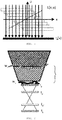
- This tomographic distribution of the wavefront phase will have the original two-dimensional optical resolution associated with the capture sensor and the three-dimensional resolution (in optical axis z ) that the number of images used allows. It should be pointed out that the three-dimensional resolution does not strictly coincide with the number of planes or defocused images acquired, as it is possible to consider any pair of acquisition planes for obtaining subdiscretization of accumulated wavefront phases, as schematically depicted in Figure 6 .
- the method of the present invention can be applied in any technical field in which the wavefront associated with the observation of a scene is to be known, including computational photography and adaptive optics, particularly in applications relating to astronomical observations to obtain a three-dimensional map of turbulences (wavefront phases) associated with a column of the atmosphere, in applications in which it is necessary to correct the view through turbulent media (for example in augmented reality glasses, mobiles, microscopes, or endoscopes), in applications for the tomographic measurement of variations in refractive index in transparent organic tissue samples or in applications of optic communications through turbulent media (atmosphere, ocean, body fluids, etc.).
- turbulent media for example in augmented reality glasses, mobiles, microscopes, or endoscopes
- the light field L is a four-dimensional representation of the light rays going through the objective of a camera.
- Ng Ng, R., Fourier slice photography, in ACM Transactions on Graphics (TOG), Vol. 24, No. 3, pp. 735-744, ACM, 2005, July
- the method of the invention is based on interpreting I ⁇ ( x ) as a sum of images at different values u displaced with respect to one another, as schematically depicted in Figure 5 , and on estimating images at different values u , finding which set of images that are displaced due to a value ⁇ ' and added to one another best approximates the input image captured with a focus distance F ⁇ '. Displacement in the x dimension (in pixels) is therefore u +( x-u )/ ⁇ ' .
- the method comprises estimating the value of the light field focused at distance F ( L F ) at M values other than u from P images ( I 1 ( x ), I 2 ( x )... I P ( x )) focused at distances ⁇ 1 F, ⁇ 2 F ... ⁇ P F and captured with a conventional photographic camera.
- the method for recomposing the intensity of the image according to the invention allows generating a single image that is completely focused and with complete optical resolution (all-in-focus), generating the all-in-focus stereo pair, generating an all-in-focus multi-stereo image (light field) and generating a light field focused at will where desired, with applications in microscopy, photography, endoscopy, cinematography, etc.
- the resolution of the preceding system provides the values of the light field L F .
- the values of the light field that are not defined in any equation in the preceding system take the value 0.
- Figure 7 shows the image recomposition of a scene performed in transform domain, according to a method from the state of the art.
- Figure 8 shows the image recomposition of the same scene performed in measurement domain, using the method of the present invention for obtaining the light field from defocused images.
- the images of Figures 7 and 8 are not normalized to the same signal strength value, it can be seen that the recomposition performed in the measurement domain is better defined and sharper at the edges of the resolution test figures.
- the area marked in the box and enlarged so it can be seen better perfectly illustrates the difference in quality between both retrievals.
Landscapes
- Physics & Mathematics (AREA)
- Spectroscopy & Molecular Physics (AREA)
- General Physics & Mathematics (AREA)
- Engineering & Computer Science (AREA)
- Multimedia (AREA)
- Signal Processing (AREA)
- Investigating Or Analysing Materials By Optical Means (AREA)
- Image Processing (AREA)
- Studio Devices (AREA)
- Optics & Photonics (AREA)
- Lenses (AREA)
Claims (11)
- Verfahren zum Bestimmen der komplexen Amplitude des elektromagnetischen Feldes, welches mit einer Szene assoziiert ist, aufweisend die folgenden Schritte:a) Aufnehmen einer Mehrzahl von Bildern der Szene mittels einer Fotokamera, wobei die Bilder in Fokusebenen fokussiert sind, die bei unterschiedlichen Abständen angeordnet sind, wobei die Kamera eine Linse oder ein System von Linsen mit einer Fokallänge F und einen Sensor aufweist, welcher in einem bestimmten Abstand von der Linse im Bildraum angeordnet ist,b) Verwenden mindestens eines Bildpaares aus der Mehrzahl von Bildern und Bestimmen der akkumulierten Wellenfront zur konjugierten Ebene im Objektraum, welche der Zwischenebene bezüglich der Fokalebenen der beiden Bilder des Bildpaares entspricht, Bestimmen der Wellenfront W(x,y) als:

wobei die Koeffizienten dj bestimmt werden durch Lösen des Gleichungssystems:


- Verfahren gemäß Anspruch 1, wobei die Wellenfront durch den Ausdruck


- Verfahren gemäß einem der vorangehenden Ansprüche, welches Bestimmen der akkumulierten Wellenfront für eine Mehrzahl von Bildpaaren aufweist.
- Verfahren gemäß Anspruch 3, welches Bestimmen der Phasenverschiebung zwischen zwei Ebenen des Objektraums aufweist als die Subtraktion der kumulierten Wellenfronten zu den besagten Ebenen.
- Verfahren gemäß Anspruch 4, welches Bestimmen der Phasenverschiebung für eine Mehrzahl von Objektebenen aufweist.
- Verfahren gemäß einem der vorangehenden Ansprüche, welches ferner aufweist:
Bestimmen aus P Bildern, welche aus der Mehrzahl von erfassten Bildern ausgewählt sind, den Wert des bei Abstand F fokussierten Lichtfeldes (L) bei M Werten, die sich von u unterscheiden, M≤P, als die Werte des Lichtfeldes, welches das Gleichungssystem erfüllt:
Erhalten als Ergebnis für jedes Bild j, mit 1≤j≤P, das Lichtfeld LF(x) ausgewertet bei dem Wert von uj, welcher aus der Annäherung resultiert, d. h., die Ansicht des dem Wert uj entsprechenden Lichtfeldes, wobei x und u die zweidimensionalen Vektoren sind, welche die Position im Sensor bzw. in der Linse der Kamera bestimmen. - Verfahren gemäß Anspruch 6, wobei der Wert des Lichtfeldes bestimmt wird durch Lösen des Gleichungssystems mittels der Methode der kleinsten Quadrate, d. h. durch Minimieren von:

- Verfahren gemäß einem der vorangehenden Ansprüche, wobei die zwei Bilder jedes der ausgewählten Bildpaare auf beiden Seiten des Fokus aufgenommen werden.
- Verfahren gemäß einem der vorangehenden Ansprüche, wobei die zwei Bilder jedes ausgewählten Bildpaares aus symmetrischen Abständen auf beiden Seiten des Fokus aufgenommen werden.
- Eine Vorrichtung zum Bestimmen der Amplitude des elektromagnetischen Feldes, welches mit einer Szene assoziiert ist, aufweisend
Mittel zum Aufnehmen von Bildern aufweisend eine Linse mit einer fokale Länge F und einen Bildsensor, welcher parallel zur Linse angeordnet ist bei einem bestimmten Abstand von der Linse in seinem Bildraum, und
Verarbeitungsmittel, eingerichtet Schritt b) des Verfahrens gemäß Anspruch 1 auszuführen. - Vorrichtung gemäß Anspruch 10, wobei das Verarbeitungsmittel zusätzlich eingerichtet ist zum Ausführen der Vorgänge, wie sie in einem der Ansprüche 2-9 definiert sind.
Applications Claiming Priority (2)
| Application Number | Priority Date | Filing Date | Title |
|---|---|---|---|
| ES201431900A ES2578356B1 (es) | 2014-12-22 | 2014-12-22 | Método para determinar la amplitud compleja del campo electromagnético asociado a una escena |
| PCT/ES2015/070936 WO2016102731A1 (es) | 2014-12-22 | 2015-12-21 | Método para determinar la amplitud compleja del campo electromagnético asociado a una escena |
Publications (3)
| Publication Number | Publication Date |
|---|---|
| EP3239672A1 EP3239672A1 (de) | 2017-11-01 |
| EP3239672A4 EP3239672A4 (de) | 2018-09-19 |
| EP3239672B1 true EP3239672B1 (de) | 2020-01-15 |
Family
ID=56149310
Family Applications (1)
| Application Number | Title | Priority Date | Filing Date |
|---|---|---|---|
| EP15872012.8A Active EP3239672B1 (de) | 2014-12-22 | 2015-12-21 | Verfahren zur bestimmung der komplexen amplitude des elektromagnetischen feldes im zusammenhang mit einer szene |
Country Status (10)
| Country | Link |
|---|---|
| US (1) | US10230940B2 (de) |
| EP (1) | EP3239672B1 (de) |
| JP (1) | JP6600360B2 (de) |
| KR (1) | KR102501402B1 (de) |
| CN (1) | CN107209061B (de) |
| DK (1) | DK3239672T3 (de) |
| ES (1) | ES2578356B1 (de) |
| IL (1) | IL253142B (de) |
| TW (1) | TWI687661B (de) |
| WO (1) | WO2016102731A1 (de) |
Families Citing this family (5)
| Publication number | Priority date | Publication date | Assignee | Title |
|---|---|---|---|---|
| WO2017180615A1 (en) | 2016-04-12 | 2017-10-19 | Quidient, Llc | Quotidian scene reconstruction engine |
| AU2017202910A1 (en) * | 2017-05-02 | 2018-11-22 | Canon Kabushiki Kaisha | Image processing for turbulence compensation |
| US11875476B2 (en) | 2018-05-02 | 2024-01-16 | Quidient, Llc | Codec for processing scenes of almost unlimited detail |
| US10565085B2 (en) * | 2018-06-06 | 2020-02-18 | Sas Institute, Inc. | Two-stage distributed estimation system |
| CN108873363B (zh) * | 2018-09-06 | 2023-11-17 | 深圳技术大学(筹) | 基于结构光标记的三维光场成像系统及方法 |
Family Cites Families (7)
| Publication number | Priority date | Publication date | Assignee | Title |
|---|---|---|---|---|
| US8542421B2 (en) * | 2006-11-17 | 2013-09-24 | Celloptic, Inc. | System, apparatus and method for extracting three-dimensional information of an object from received electromagnetic radiation |
| US8405890B2 (en) * | 2007-01-29 | 2013-03-26 | Celloptic, Inc. | System, apparatus and method for extracting image cross-sections of an object from received electromagnetic radiation |
| ES2372515B2 (es) * | 2008-01-15 | 2012-10-16 | Universidad De La Laguna | Cámara para la adquisición en tiempo real de la información visual de escenas tridimensionales. |
| CN101939703B (zh) | 2008-12-25 | 2011-08-31 | 深圳市泛彩溢实业有限公司 | 全息三维图像信息采集装置、方法及还原装置、方法 |
| JP2010169976A (ja) * | 2009-01-23 | 2010-08-05 | Sony Corp | 空間像表示装置 |
| JP2013519980A (ja) * | 2010-02-10 | 2013-05-30 | モチイ,インコーポレイテッド(ディービーエー ヴォクサ) | 収差補正暗視野電子顕微鏡 |
| CN102662238B (zh) | 2012-05-03 | 2014-01-15 | 中国科学院长春光学精密机械与物理研究所 | 一种具有在轨自诊断和补偿功能的空间光学相机 |
-
2014
- 2014-12-22 ES ES201431900A patent/ES2578356B1/es active Active
-
2015
- 2015-12-21 EP EP15872012.8A patent/EP3239672B1/de active Active
- 2015-12-21 CN CN201580072973.9A patent/CN107209061B/zh active Active
- 2015-12-21 JP JP2017533821A patent/JP6600360B2/ja active Active
- 2015-12-21 KR KR1020177020020A patent/KR102501402B1/ko active IP Right Grant
- 2015-12-21 US US15/538,849 patent/US10230940B2/en active Active
- 2015-12-21 WO PCT/ES2015/070936 patent/WO2016102731A1/es active Application Filing
- 2015-12-21 DK DK15872012.8T patent/DK3239672T3/da active
- 2015-12-22 TW TW104143159A patent/TWI687661B/zh active
-
2017
- 2017-06-22 IL IL253142A patent/IL253142B/en unknown
Non-Patent Citations (1)
| Title |
|---|
| None * |
Also Published As
| Publication number | Publication date |
|---|---|
| CN107209061A (zh) | 2017-09-26 |
| IL253142A0 (en) | 2017-08-31 |
| CN107209061B (zh) | 2020-04-14 |
| DK3239672T3 (da) | 2020-04-14 |
| EP3239672A4 (de) | 2018-09-19 |
| KR102501402B1 (ko) | 2023-02-20 |
| US10230940B2 (en) | 2019-03-12 |
| JP6600360B2 (ja) | 2019-10-30 |
| TWI687661B (zh) | 2020-03-11 |
| JP2018512070A (ja) | 2018-05-10 |
| ES2578356B1 (es) | 2017-08-04 |
| IL253142B (en) | 2021-07-29 |
| EP3239672A1 (de) | 2017-11-01 |
| US20180007342A1 (en) | 2018-01-04 |
| WO2016102731A1 (es) | 2016-06-30 |
| KR20170099959A (ko) | 2017-09-01 |
| TW201643391A (zh) | 2016-12-16 |
| ES2578356A1 (es) | 2016-07-26 |
Similar Documents
| Publication | Publication Date | Title |
|---|---|---|
| EP3239672B1 (de) | Verfahren zur bestimmung der komplexen amplitude des elektromagnetischen feldes im zusammenhang mit einer szene | |
| US8432479B2 (en) | Range measurement using a zoom camera | |
| DK2239706T3 (en) | A method for real-time camera and obtaining visual information of three-dimensional scenes | |
| US8305485B2 (en) | Digital camera with coded aperture rangefinder | |
| US8773550B2 (en) | Range measurement using multiple coded apertures | |
| US20070278386A1 (en) | Measurement-diverse imaging and wavefront sensing with amplitude and phase estimation | |
| CN110476043B (zh) | 用于采集电磁场的波前的断层成像分布的方法和光学系统 | |
| Rodríguez-Ramos et al. | Concepts, laboratory, and telescope test results of the plenoptic camera as a wavefront sensor | |
| Estrada et al. | Multi-frame image fusion using a machine learning-based weight mask predictor for turbulence-induced image degradation | |
| Martinello | Coded aperture imaging | |
| Wang et al. | Parameterized modeling of spatially varying PSF for lens aberration and defocus | |
| US20240126073A1 (en) | Method and system for passive range imaging | |
| Hart et al. | Application of dOTF wavefront sensing to 3D aberration measurement in an optical system | |
| Willson et al. | Tomographic Wave Front Sensing using a Single Imaging Shack-Hartmann Wave Front Sensor and Multi-Frame Blind Deconvolution |
Legal Events
| Date | Code | Title | Description |
|---|---|---|---|
| STAA | Information on the status of an ep patent application or granted ep patent |
Free format text: STATUS: THE INTERNATIONAL PUBLICATION HAS BEEN MADE |
|
| PUAI | Public reference made under article 153(3) epc to a published international application that has entered the european phase |
Free format text: ORIGINAL CODE: 0009012 |
|
| STAA | Information on the status of an ep patent application or granted ep patent |
Free format text: STATUS: REQUEST FOR EXAMINATION WAS MADE |
|
| 17P | Request for examination filed |
Effective date: 20170706 |
|
| AK | Designated contracting states |
Kind code of ref document: A1 Designated state(s): AL AT BE BG CH CY CZ DE DK EE ES FI FR GB GR HR HU IE IS IT LI LT LU LV MC MK MT NL NO PL PT RO RS SE SI SK SM TR |
|
| AX | Request for extension of the european patent |
Extension state: BA ME |
|
| DAV | Request for validation of the european patent (deleted) | ||
| DAX | Request for extension of the european patent (deleted) | ||
| A4 | Supplementary search report drawn up and despatched |
Effective date: 20180820 |
|
| RIC1 | Information provided on ipc code assigned before grant |
Ipc: G02B 27/22 20060101ALI20180813BHEP Ipc: G01J 11/00 20060101AFI20180813BHEP |
|
| GRAP | Despatch of communication of intention to grant a patent |
Free format text: ORIGINAL CODE: EPIDOSNIGR1 |
|
| STAA | Information on the status of an ep patent application or granted ep patent |
Free format text: STATUS: GRANT OF PATENT IS INTENDED |
|
| INTG | Intention to grant announced |
Effective date: 20190729 |
|
| GRAS | Grant fee paid |
Free format text: ORIGINAL CODE: EPIDOSNIGR3 |
|
| GRAA | (expected) grant |
Free format text: ORIGINAL CODE: 0009210 |
|
| STAA | Information on the status of an ep patent application or granted ep patent |
Free format text: STATUS: THE PATENT HAS BEEN GRANTED |
|
| AK | Designated contracting states |
Kind code of ref document: B1 Designated state(s): AL AT BE BG CH CY CZ DE DK EE ES FI FR GB GR HR HU IE IS IT LI LT LU LV MC MK MT NL NO PL PT RO RS SE SI SK SM TR |
|
| REG | Reference to a national code |
Ref country code: CH Ref legal event code: EP Ref country code: GB Ref legal event code: FG4D |
|
| REG | Reference to a national code |
Ref country code: IE Ref legal event code: FG4D |
|
| REG | Reference to a national code |
Ref country code: DE Ref legal event code: R096 Ref document number: 602015045816 Country of ref document: DE |
|
| REG | Reference to a national code |
Ref country code: AT Ref legal event code: REF Ref document number: 1225551 Country of ref document: AT Kind code of ref document: T Effective date: 20200215 |
|
| REG | Reference to a national code |
Ref country code: DK Ref legal event code: T3 Effective date: 20200409 |
|
| REG | Reference to a national code |
Ref country code: FI Ref legal event code: FGE |
|
| REG | Reference to a national code |
Ref country code: NL Ref legal event code: FP |
|
| REG | Reference to a national code |
Ref country code: LT Ref legal event code: MG4D |
|
| PG25 | Lapsed in a contracting state [announced via postgrant information from national office to epo] |
Ref country code: PT Free format text: LAPSE BECAUSE OF FAILURE TO SUBMIT A TRANSLATION OF THE DESCRIPTION OR TO PAY THE FEE WITHIN THE PRESCRIBED TIME-LIMIT Effective date: 20200607 Ref country code: RS Free format text: LAPSE BECAUSE OF FAILURE TO SUBMIT A TRANSLATION OF THE DESCRIPTION OR TO PAY THE FEE WITHIN THE PRESCRIBED TIME-LIMIT Effective date: 20200115 Ref country code: NO Free format text: LAPSE BECAUSE OF FAILURE TO SUBMIT A TRANSLATION OF THE DESCRIPTION OR TO PAY THE FEE WITHIN THE PRESCRIBED TIME-LIMIT Effective date: 20200415 |
|
| PG25 | Lapsed in a contracting state [announced via postgrant information from national office to epo] |
Ref country code: HR Free format text: LAPSE BECAUSE OF FAILURE TO SUBMIT A TRANSLATION OF THE DESCRIPTION OR TO PAY THE FEE WITHIN THE PRESCRIBED TIME-LIMIT Effective date: 20200115 Ref country code: LV Free format text: LAPSE BECAUSE OF FAILURE TO SUBMIT A TRANSLATION OF THE DESCRIPTION OR TO PAY THE FEE WITHIN THE PRESCRIBED TIME-LIMIT Effective date: 20200115 Ref country code: BG Free format text: LAPSE BECAUSE OF FAILURE TO SUBMIT A TRANSLATION OF THE DESCRIPTION OR TO PAY THE FEE WITHIN THE PRESCRIBED TIME-LIMIT Effective date: 20200415 Ref country code: GR Free format text: LAPSE BECAUSE OF FAILURE TO SUBMIT A TRANSLATION OF THE DESCRIPTION OR TO PAY THE FEE WITHIN THE PRESCRIBED TIME-LIMIT Effective date: 20200416 Ref country code: IS Free format text: LAPSE BECAUSE OF FAILURE TO SUBMIT A TRANSLATION OF THE DESCRIPTION OR TO PAY THE FEE WITHIN THE PRESCRIBED TIME-LIMIT Effective date: 20200515 Ref country code: SE Free format text: LAPSE BECAUSE OF FAILURE TO SUBMIT A TRANSLATION OF THE DESCRIPTION OR TO PAY THE FEE WITHIN THE PRESCRIBED TIME-LIMIT Effective date: 20200115 |
|
| REG | Reference to a national code |
Ref country code: DE Ref legal event code: R097 Ref document number: 602015045816 Country of ref document: DE |
|
| PG25 | Lapsed in a contracting state [announced via postgrant information from national office to epo] |
Ref country code: LT Free format text: LAPSE BECAUSE OF FAILURE TO SUBMIT A TRANSLATION OF THE DESCRIPTION OR TO PAY THE FEE WITHIN THE PRESCRIBED TIME-LIMIT Effective date: 20200115 Ref country code: EE Free format text: LAPSE BECAUSE OF FAILURE TO SUBMIT A TRANSLATION OF THE DESCRIPTION OR TO PAY THE FEE WITHIN THE PRESCRIBED TIME-LIMIT Effective date: 20200115 Ref country code: SM Free format text: LAPSE BECAUSE OF FAILURE TO SUBMIT A TRANSLATION OF THE DESCRIPTION OR TO PAY THE FEE WITHIN THE PRESCRIBED TIME-LIMIT Effective date: 20200115 Ref country code: RO Free format text: LAPSE BECAUSE OF FAILURE TO SUBMIT A TRANSLATION OF THE DESCRIPTION OR TO PAY THE FEE WITHIN THE PRESCRIBED TIME-LIMIT Effective date: 20200115 Ref country code: CZ Free format text: LAPSE BECAUSE OF FAILURE TO SUBMIT A TRANSLATION OF THE DESCRIPTION OR TO PAY THE FEE WITHIN THE PRESCRIBED TIME-LIMIT Effective date: 20200115 Ref country code: ES Free format text: LAPSE BECAUSE OF FAILURE TO SUBMIT A TRANSLATION OF THE DESCRIPTION OR TO PAY THE FEE WITHIN THE PRESCRIBED TIME-LIMIT Effective date: 20200115 Ref country code: SK Free format text: LAPSE BECAUSE OF FAILURE TO SUBMIT A TRANSLATION OF THE DESCRIPTION OR TO PAY THE FEE WITHIN THE PRESCRIBED TIME-LIMIT Effective date: 20200115 |
|
| REG | Reference to a national code |
Ref country code: AT Ref legal event code: MK05 Ref document number: 1225551 Country of ref document: AT Kind code of ref document: T Effective date: 20200115 |
|
| PLBE | No opposition filed within time limit |
Free format text: ORIGINAL CODE: 0009261 |
|
| STAA | Information on the status of an ep patent application or granted ep patent |
Free format text: STATUS: NO OPPOSITION FILED WITHIN TIME LIMIT |
|
| 26N | No opposition filed |
Effective date: 20201016 |
|
| PG25 | Lapsed in a contracting state [announced via postgrant information from national office to epo] |
Ref country code: AT Free format text: LAPSE BECAUSE OF FAILURE TO SUBMIT A TRANSLATION OF THE DESCRIPTION OR TO PAY THE FEE WITHIN THE PRESCRIBED TIME-LIMIT Effective date: 20200115 |
|
| PG25 | Lapsed in a contracting state [announced via postgrant information from national office to epo] |
Ref country code: SI Free format text: LAPSE BECAUSE OF FAILURE TO SUBMIT A TRANSLATION OF THE DESCRIPTION OR TO PAY THE FEE WITHIN THE PRESCRIBED TIME-LIMIT Effective date: 20200115 Ref country code: PL Free format text: LAPSE BECAUSE OF FAILURE TO SUBMIT A TRANSLATION OF THE DESCRIPTION OR TO PAY THE FEE WITHIN THE PRESCRIBED TIME-LIMIT Effective date: 20200115 |
|
| REG | Reference to a national code |
Ref country code: CH Ref legal event code: PL |
|
| PG25 | Lapsed in a contracting state [announced via postgrant information from national office to epo] |
Ref country code: MC Free format text: LAPSE BECAUSE OF FAILURE TO SUBMIT A TRANSLATION OF THE DESCRIPTION OR TO PAY THE FEE WITHIN THE PRESCRIBED TIME-LIMIT Effective date: 20200115 |
|
| PG25 | Lapsed in a contracting state [announced via postgrant information from national office to epo] |
Ref country code: LU Free format text: LAPSE BECAUSE OF NON-PAYMENT OF DUE FEES Effective date: 20201221 |
|
| PG25 | Lapsed in a contracting state [announced via postgrant information from national office to epo] |
Ref country code: LI Free format text: LAPSE BECAUSE OF NON-PAYMENT OF DUE FEES Effective date: 20201231 Ref country code: CH Free format text: LAPSE BECAUSE OF NON-PAYMENT OF DUE FEES Effective date: 20201231 |
|
| PG25 | Lapsed in a contracting state [announced via postgrant information from national office to epo] |
Ref country code: TR Free format text: LAPSE BECAUSE OF FAILURE TO SUBMIT A TRANSLATION OF THE DESCRIPTION OR TO PAY THE FEE WITHIN THE PRESCRIBED TIME-LIMIT Effective date: 20200115 Ref country code: MT Free format text: LAPSE BECAUSE OF FAILURE TO SUBMIT A TRANSLATION OF THE DESCRIPTION OR TO PAY THE FEE WITHIN THE PRESCRIBED TIME-LIMIT Effective date: 20200115 Ref country code: CY Free format text: LAPSE BECAUSE OF FAILURE TO SUBMIT A TRANSLATION OF THE DESCRIPTION OR TO PAY THE FEE WITHIN THE PRESCRIBED TIME-LIMIT Effective date: 20200115 |
|
| PG25 | Lapsed in a contracting state [announced via postgrant information from national office to epo] |
Ref country code: MK Free format text: LAPSE BECAUSE OF FAILURE TO SUBMIT A TRANSLATION OF THE DESCRIPTION OR TO PAY THE FEE WITHIN THE PRESCRIBED TIME-LIMIT Effective date: 20200115 Ref country code: AL Free format text: LAPSE BECAUSE OF FAILURE TO SUBMIT A TRANSLATION OF THE DESCRIPTION OR TO PAY THE FEE WITHIN THE PRESCRIBED TIME-LIMIT Effective date: 20200115 |
|
| PGFP | Annual fee paid to national office [announced via postgrant information from national office to epo] |
Ref country code: GB Payment date: 20231227 Year of fee payment: 9 |
|
| PGFP | Annual fee paid to national office [announced via postgrant information from national office to epo] |
Ref country code: NL Payment date: 20231226 Year of fee payment: 9 Ref country code: IT Payment date: 20231220 Year of fee payment: 9 Ref country code: IE Payment date: 20231227 Year of fee payment: 9 Ref country code: FR Payment date: 20231227 Year of fee payment: 9 Ref country code: FI Payment date: 20231227 Year of fee payment: 9 Ref country code: DK Payment date: 20231229 Year of fee payment: 9 |
|
| PGFP | Annual fee paid to national office [announced via postgrant information from national office to epo] |
Ref country code: BE Payment date: 20231227 Year of fee payment: 9 |
|
| PGFP | Annual fee paid to national office [announced via postgrant information from national office to epo] |
Ref country code: DE Payment date: 20231229 Year of fee payment: 9 |