EP3239598A1 - Rotary light module - Google Patents
Rotary light module Download PDFInfo
- Publication number
- EP3239598A1 EP3239598A1 EP17167370.0A EP17167370A EP3239598A1 EP 3239598 A1 EP3239598 A1 EP 3239598A1 EP 17167370 A EP17167370 A EP 17167370A EP 3239598 A1 EP3239598 A1 EP 3239598A1
- Authority
- EP
- European Patent Office
- Prior art keywords
- support
- light
- rotation
- face
- light source
- Prior art date
- Legal status (The legal status is an assumption and is not a legal conclusion. Google has not performed a legal analysis and makes no representation as to the accuracy of the status listed.)
- Granted
Links
- 230000003287 optical effect Effects 0.000 claims abstract description 65
- 230000002093 peripheral effect Effects 0.000 claims description 19
- 230000011664 signaling Effects 0.000 claims description 18
- 238000003754 machining Methods 0.000 claims description 2
- 238000006073 displacement reaction Methods 0.000 description 5
- 239000000463 material Substances 0.000 description 5
- 230000000694 effects Effects 0.000 description 4
- 230000001105 regulatory effect Effects 0.000 description 4
- 229910052782 aluminium Inorganic materials 0.000 description 3
- XAGFODPZIPBFFR-UHFFFAOYSA-N aluminium Chemical compound [Al] XAGFODPZIPBFFR-UHFFFAOYSA-N 0.000 description 3
- 239000007769 metal material Substances 0.000 description 3
- 239000000758 substrate Substances 0.000 description 3
- 229930040373 Paraformaldehyde Natural products 0.000 description 2
- 230000015572 biosynthetic process Effects 0.000 description 2
- BASFCYQUMIYNBI-UHFFFAOYSA-N platinum Chemical compound [Pt] BASFCYQUMIYNBI-UHFFFAOYSA-N 0.000 description 2
- 229920006324 polyoxymethylene Polymers 0.000 description 2
- 239000004065 semiconductor Substances 0.000 description 2
- 238000011144 upstream manufacturing Methods 0.000 description 2
- 230000003044 adaptive effect Effects 0.000 description 1
- 238000004026 adhesive bonding Methods 0.000 description 1
- 239000004411 aluminium Substances 0.000 description 1
- 230000015556 catabolic process Effects 0.000 description 1
- 230000000295 complement effect Effects 0.000 description 1
- 230000001276 controlling effect Effects 0.000 description 1
- 230000006378 damage Effects 0.000 description 1
- 238000006731 degradation reaction Methods 0.000 description 1
- 238000001514 detection method Methods 0.000 description 1
- 230000009977 dual effect Effects 0.000 description 1
- 239000002783 friction material Substances 0.000 description 1
- 239000011521 glass Substances 0.000 description 1
- 238000005286 illumination Methods 0.000 description 1
- 230000002452 interceptive effect Effects 0.000 description 1
- 238000012423 maintenance Methods 0.000 description 1
- 238000007747 plating Methods 0.000 description 1
- 229910052697 platinum Inorganic materials 0.000 description 1
- -1 polyoxymethylene Polymers 0.000 description 1
- 230000002028 premature Effects 0.000 description 1
- 238000000926 separation method Methods 0.000 description 1
- 238000003466 welding Methods 0.000 description 1
Images
Classifications
-
- F—MECHANICAL ENGINEERING; LIGHTING; HEATING; WEAPONS; BLASTING
- F21—LIGHTING
- F21V—FUNCTIONAL FEATURES OR DETAILS OF LIGHTING DEVICES OR SYSTEMS THEREOF; STRUCTURAL COMBINATIONS OF LIGHTING DEVICES WITH OTHER ARTICLES, NOT OTHERWISE PROVIDED FOR
- F21V17/00—Fastening of component parts of lighting devices, e.g. shades, globes, refractors, reflectors, filters, screens, grids or protective cages
- F21V17/02—Fastening of component parts of lighting devices, e.g. shades, globes, refractors, reflectors, filters, screens, grids or protective cages with provision for adjustment
-
- F—MECHANICAL ENGINEERING; LIGHTING; HEATING; WEAPONS; BLASTING
- F21—LIGHTING
- F21S—NON-PORTABLE LIGHTING DEVICES; SYSTEMS THEREOF; VEHICLE LIGHTING DEVICES SPECIALLY ADAPTED FOR VEHICLE EXTERIORS
- F21S41/00—Illuminating devices specially adapted for vehicle exteriors, e.g. headlamps
- F21S41/10—Illuminating devices specially adapted for vehicle exteriors, e.g. headlamps characterised by the light source
- F21S41/14—Illuminating devices specially adapted for vehicle exteriors, e.g. headlamps characterised by the light source characterised by the type of light source
- F21S41/141—Light emitting diodes [LED]
-
- B—PERFORMING OPERATIONS; TRANSPORTING
- B60—VEHICLES IN GENERAL
- B60Q—ARRANGEMENT OF SIGNALLING OR LIGHTING DEVICES, THE MOUNTING OR SUPPORTING THEREOF OR CIRCUITS THEREFOR, FOR VEHICLES IN GENERAL
- B60Q1/00—Arrangement of optical signalling or lighting devices, the mounting or supporting thereof or circuits therefor
- B60Q1/02—Arrangement of optical signalling or lighting devices, the mounting or supporting thereof or circuits therefor the devices being primarily intended to illuminate the way ahead or to illuminate other areas of way or environments
- B60Q1/04—Arrangement of optical signalling or lighting devices, the mounting or supporting thereof or circuits therefor the devices being primarily intended to illuminate the way ahead or to illuminate other areas of way or environments the devices being headlights
- B60Q1/06—Arrangement of optical signalling or lighting devices, the mounting or supporting thereof or circuits therefor the devices being primarily intended to illuminate the way ahead or to illuminate other areas of way or environments the devices being headlights adjustable, e.g. remotely-controlled from inside vehicle
- B60Q1/076—Arrangement of optical signalling or lighting devices, the mounting or supporting thereof or circuits therefor the devices being primarily intended to illuminate the way ahead or to illuminate other areas of way or environments the devices being headlights adjustable, e.g. remotely-controlled from inside vehicle by electrical means including means to transmit the movements, e.g. shafts or joints
-
- B—PERFORMING OPERATIONS; TRANSPORTING
- B60—VEHICLES IN GENERAL
- B60R—VEHICLES, VEHICLE FITTINGS, OR VEHICLE PARTS, NOT OTHERWISE PROVIDED FOR
- B60R16/00—Electric or fluid circuits specially adapted for vehicles and not otherwise provided for; Arrangement of elements of electric or fluid circuits specially adapted for vehicles and not otherwise provided for
- B60R16/02—Electric or fluid circuits specially adapted for vehicles and not otherwise provided for; Arrangement of elements of electric or fluid circuits specially adapted for vehicles and not otherwise provided for electric constitutive elements
- B60R16/0207—Wire harnesses
- B60R16/0215—Protecting, fastening and routing means therefor
-
- F—MECHANICAL ENGINEERING; LIGHTING; HEATING; WEAPONS; BLASTING
- F21—LIGHTING
- F21S—NON-PORTABLE LIGHTING DEVICES; SYSTEMS THEREOF; VEHICLE LIGHTING DEVICES SPECIALLY ADAPTED FOR VEHICLE EXTERIORS
- F21S41/00—Illuminating devices specially adapted for vehicle exteriors, e.g. headlamps
- F21S41/10—Illuminating devices specially adapted for vehicle exteriors, e.g. headlamps characterised by the light source
- F21S41/19—Attachment of light sources or lamp holders
- F21S41/192—Details of lamp holders, terminals or connectors
-
- F—MECHANICAL ENGINEERING; LIGHTING; HEATING; WEAPONS; BLASTING
- F21—LIGHTING
- F21S—NON-PORTABLE LIGHTING DEVICES; SYSTEMS THEREOF; VEHICLE LIGHTING DEVICES SPECIALLY ADAPTED FOR VEHICLE EXTERIORS
- F21S41/00—Illuminating devices specially adapted for vehicle exteriors, e.g. headlamps
- F21S41/30—Illuminating devices specially adapted for vehicle exteriors, e.g. headlamps characterised by reflectors
- F21S41/32—Optical layout thereof
-
- F—MECHANICAL ENGINEERING; LIGHTING; HEATING; WEAPONS; BLASTING
- F21—LIGHTING
- F21S—NON-PORTABLE LIGHTING DEVICES; SYSTEMS THEREOF; VEHICLE LIGHTING DEVICES SPECIALLY ADAPTED FOR VEHICLE EXTERIORS
- F21S41/00—Illuminating devices specially adapted for vehicle exteriors, e.g. headlamps
- F21S41/50—Illuminating devices specially adapted for vehicle exteriors, e.g. headlamps characterised by aesthetic components not otherwise provided for, e.g. decorative trim, partition walls or covers
- F21S41/55—Attachment thereof
-
- F—MECHANICAL ENGINEERING; LIGHTING; HEATING; WEAPONS; BLASTING
- F21—LIGHTING
- F21S—NON-PORTABLE LIGHTING DEVICES; SYSTEMS THEREOF; VEHICLE LIGHTING DEVICES SPECIALLY ADAPTED FOR VEHICLE EXTERIORS
- F21S41/00—Illuminating devices specially adapted for vehicle exteriors, e.g. headlamps
- F21S41/60—Illuminating devices specially adapted for vehicle exteriors, e.g. headlamps characterised by a variable light distribution
- F21S41/67—Illuminating devices specially adapted for vehicle exteriors, e.g. headlamps characterised by a variable light distribution by acting on reflectors
- F21S41/675—Illuminating devices specially adapted for vehicle exteriors, e.g. headlamps characterised by a variable light distribution by acting on reflectors by moving reflectors
-
- F—MECHANICAL ENGINEERING; LIGHTING; HEATING; WEAPONS; BLASTING
- F21—LIGHTING
- F21S—NON-PORTABLE LIGHTING DEVICES; SYSTEMS THEREOF; VEHICLE LIGHTING DEVICES SPECIALLY ADAPTED FOR VEHICLE EXTERIORS
- F21S43/00—Signalling devices specially adapted for vehicle exteriors, e.g. brake lamps, direction indicator lights or reversing lights
- F21S43/10—Signalling devices specially adapted for vehicle exteriors, e.g. brake lamps, direction indicator lights or reversing lights characterised by the light source
- F21S43/13—Signalling devices specially adapted for vehicle exteriors, e.g. brake lamps, direction indicator lights or reversing lights characterised by the light source characterised by the type of light source
- F21S43/14—Light emitting diodes [LED]
-
- F—MECHANICAL ENGINEERING; LIGHTING; HEATING; WEAPONS; BLASTING
- F21—LIGHTING
- F21S—NON-PORTABLE LIGHTING DEVICES; SYSTEMS THEREOF; VEHICLE LIGHTING DEVICES SPECIALLY ADAPTED FOR VEHICLE EXTERIORS
- F21S43/00—Signalling devices specially adapted for vehicle exteriors, e.g. brake lamps, direction indicator lights or reversing lights
- F21S43/10—Signalling devices specially adapted for vehicle exteriors, e.g. brake lamps, direction indicator lights or reversing lights characterised by the light source
- F21S43/19—Attachment of light sources or lamp holders
- F21S43/195—Details of lamp holders, terminals or connectors
-
- F—MECHANICAL ENGINEERING; LIGHTING; HEATING; WEAPONS; BLASTING
- F21—LIGHTING
- F21S—NON-PORTABLE LIGHTING DEVICES; SYSTEMS THEREOF; VEHICLE LIGHTING DEVICES SPECIALLY ADAPTED FOR VEHICLE EXTERIORS
- F21S43/00—Signalling devices specially adapted for vehicle exteriors, e.g. brake lamps, direction indicator lights or reversing lights
- F21S43/30—Signalling devices specially adapted for vehicle exteriors, e.g. brake lamps, direction indicator lights or reversing lights characterised by reflectors
- F21S43/31—Optical layout thereof
-
- F—MECHANICAL ENGINEERING; LIGHTING; HEATING; WEAPONS; BLASTING
- F21—LIGHTING
- F21S—NON-PORTABLE LIGHTING DEVICES; SYSTEMS THEREOF; VEHICLE LIGHTING DEVICES SPECIALLY ADAPTED FOR VEHICLE EXTERIORS
- F21S43/00—Signalling devices specially adapted for vehicle exteriors, e.g. brake lamps, direction indicator lights or reversing lights
- F21S43/50—Signalling devices specially adapted for vehicle exteriors, e.g. brake lamps, direction indicator lights or reversing lights characterised by aesthetic components not otherwise provided for, e.g. decorative trim, partition walls or covers
-
- F—MECHANICAL ENGINEERING; LIGHTING; HEATING; WEAPONS; BLASTING
- F21—LIGHTING
- F21S—NON-PORTABLE LIGHTING DEVICES; SYSTEMS THEREOF; VEHICLE LIGHTING DEVICES SPECIALLY ADAPTED FOR VEHICLE EXTERIORS
- F21S45/00—Arrangements within vehicle lighting devices specially adapted for vehicle exteriors, for purposes other than emission or distribution of light
- F21S45/40—Cooling of lighting devices
-
- F—MECHANICAL ENGINEERING; LIGHTING; HEATING; WEAPONS; BLASTING
- F21—LIGHTING
- F21V—FUNCTIONAL FEATURES OR DETAILS OF LIGHTING DEVICES OR SYSTEMS THEREOF; STRUCTURAL COMBINATIONS OF LIGHTING DEVICES WITH OTHER ARTICLES, NOT OTHERWISE PROVIDED FOR
- F21V14/00—Controlling the distribution of the light emitted by adjustment of elements
-
- F—MECHANICAL ENGINEERING; LIGHTING; HEATING; WEAPONS; BLASTING
- F21—LIGHTING
- F21V—FUNCTIONAL FEATURES OR DETAILS OF LIGHTING DEVICES OR SYSTEMS THEREOF; STRUCTURAL COMBINATIONS OF LIGHTING DEVICES WITH OTHER ARTICLES, NOT OTHERWISE PROVIDED FOR
- F21V21/00—Supporting, suspending, or attaching arrangements for lighting devices; Hand grips
- F21V21/14—Adjustable mountings
- F21V21/30—Pivoted housings or frames
-
- F—MECHANICAL ENGINEERING; LIGHTING; HEATING; WEAPONS; BLASTING
- F21—LIGHTING
- F21V—FUNCTIONAL FEATURES OR DETAILS OF LIGHTING DEVICES OR SYSTEMS THEREOF; STRUCTURAL COMBINATIONS OF LIGHTING DEVICES WITH OTHER ARTICLES, NOT OTHERWISE PROVIDED FOR
- F21V23/00—Arrangement of electric circuit elements in or on lighting devices
- F21V23/001—Arrangement of electric circuit elements in or on lighting devices the elements being electrical wires or cables
- F21V23/002—Arrangements of cables or conductors inside a lighting device, e.g. means for guiding along parts of the housing or in a pivoting arm
-
- F—MECHANICAL ENGINEERING; LIGHTING; HEATING; WEAPONS; BLASTING
- F21—LIGHTING
- F21V—FUNCTIONAL FEATURES OR DETAILS OF LIGHTING DEVICES OR SYSTEMS THEREOF; STRUCTURAL COMBINATIONS OF LIGHTING DEVICES WITH OTHER ARTICLES, NOT OTHERWISE PROVIDED FOR
- F21V29/00—Protecting lighting devices from thermal damage; Cooling or heating arrangements specially adapted for lighting devices or systems
- F21V29/50—Cooling arrangements
- F21V29/70—Cooling arrangements characterised by passive heat-dissipating elements, e.g. heat-sinks
-
- F—MECHANICAL ENGINEERING; LIGHTING; HEATING; WEAPONS; BLASTING
- F21—LIGHTING
- F21V—FUNCTIONAL FEATURES OR DETAILS OF LIGHTING DEVICES OR SYSTEMS THEREOF; STRUCTURAL COMBINATIONS OF LIGHTING DEVICES WITH OTHER ARTICLES, NOT OTHERWISE PROVIDED FOR
- F21V29/00—Protecting lighting devices from thermal damage; Cooling or heating arrangements specially adapted for lighting devices or systems
- F21V29/85—Protecting lighting devices from thermal damage; Cooling or heating arrangements specially adapted for lighting devices or systems characterised by the material
- F21V29/89—Metals
Definitions
- the invention relates to the field of lighting and / or signaling, in particular for a motor vehicle. More particularly, the invention relates to a light module for a motor vehicle, and to a lighting and / or signaling device comprising such a light module.
- Lighting and / or signaling devices may comprise one or more light modules mounted rotatably about an axis, in particular to respond to problems of adaptive lighting.
- the document EP 295 74 64 discloses a lighting and / or signaling device for a motor vehicle which comprises a housing and a set of at least two light modules, in which at least a portion of each light module is rotatably mounted about an axis under the effect of an actuator for transversely displacing the corresponding light beam at the output of the light module.
- An associated control device is able to develop separately for each light module specific lighting control instructions according to the traffic conditions.
- the object of the invention is to propose a support carrying a source of light at the origin of the light beam projected at the output of the light module, configured to allow the power supply of the light source without interfering with the rotational movement.
- a rotating light module a rotating light module.
- the invention is an improvement of the lighting and / or signaling devices for a motor vehicle known from the prior art, in particular with regard to the guidance in rotation of a light module for a transverse displacement of the light beam that it generates and as regards the management of power supply cables in such a rotation guidance.
- the subject of the invention is a light module, in particular for a motor vehicle, comprising at least one light source capable of emitting light rays, at least one support element carrying said light source, at least one light cable. supplying said at least one light source with at least one optical deflection element arranged to deflect the light rays emitted by the at least one light source to form a projected light beam at the output of the light module, a guiding device for guiding in rotation the optical deflection element about an axis of rotation, in order to transversely move the projected light beam.
- the support comprises a first portion and a second portion between which is inserted at least a portion of the rotational guiding device of the optical deflection element.
- the first part of the support carries the light source, whether directly or indirectly via for example a printed circuit board fixed on one side of this first part of the support.
- said at least one cable passes through the rotational guiding device to be connected to said light source.
- transverse displacement of the light beam it is understood that the general orientation of the projected beam output of the module, that is to say in the direction of the road scene upstream of the vehicle, varies in a plane perpendicular to the axis of rotation of the optical deflection element.
- the optical deflection element can rotate precisely around the first axis of rotation, in particular thanks to the guiding device, without this rotation being impeded by the presence of cables. since these extend substantially along the first axis of rotation, at least through the rotational guiding device, because of the specific configuration of the support.
- the wire bundle passes through the rotation guiding device substantially in the center thereof, or in other words, centered on the first axis of rotation.
- the optical deflection element is rotatable under the effect of an actuator, which may include in particular an output shaft extending along the first axis of rotation and carrying the optical deflection element.
- the actuator and the rotational guiding device are disposed on either side of the optical deflection element along the first axis of rotation. It is understood that this avoids a cantilever arrangement in which the portion of the optical deflection element opposite the actuator would tend to shift from the axis of rotation.
- a support plate of the light source and if necessary a printed circuit board associated with a light-emitting diode forming the light source, has a first carrying face of the light source and a second face disposed against the first face of the first portion of the support, said wiring harness being connected to a second opposite face of the support plate.
- the module may comprise a guide sleeve of the cable bundle fixed on the first part of the support.
- This sleeve may in particular be fixed on the first part of the support at least at the level of the impression.
- the optical deflection element may consist of a reflector of substantially elliptical shape, the light source being disposed substantially in the vicinity of a first focus of said reflector.
- the optical deflection element can also be rotatably mounted about a second axis of rotation substantially perpendicular to the first axis of rotation to move in another direction than the transverse direction previously described, for example in a vertical direction, the corresponding light beam at the output of the light module.
- the second axis of rotation is carried by the second part of the support associated with the light module.
- the invention also relates to a lighting and / or signaling device comprising at least one light module as just presented above.
- the device may comprise in particular a housing defining with a closing window a housing for receiving at least one light module.
- the light beam projected at the output of the light module is configured to pass through this closing window before being projected onto the road stage upstream of the vehicle.
- this lighting and / or signaling device comprises three light modules according to the invention.
- the light beams projected by each of the modules are configured to form a global light beam, in particular meeting regulatory standards of lighting and / or signaling of a motor vehicle.
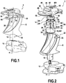
- the Figures 1 to 3 represent a light module 2 mobile in rotation about an axis of rotation 4.
- This light module 2 comprises at least one optical deflection element 6 of rays emitted by a light source 8 carried by a support 10.
- the optical deflection element or elements 6 are arranged around the axis of rotation 4 and they are driven in rotation by an actuator 12 around the axis of rotation 4 to move transversely a corresponding light beam at the output of the light module 2.
- the optical deflection elements 6 cooperate with the support 10 coming into overlap of the light module 2, in particular by means of a rotation guiding device 14 (in particular visible on the figure 2 ). It is understood that the support 10 is on the one hand carrier of the light source 8, which emits rays in the direction of the optical deflection elements 6, and on the other hand carries a portion of the rotational guiding device 14 optical deflection elements 6 about the axis of rotation 4.
- the optical deflection elements 6, which will be described in more detail below, are arranged between the guiding device 14 and the actuator 12 relative to their arrangement along the axis of rotation. of the axis of rotation 4.
- Control means drive the actuator 12. A movement is transmitted by this actuator 12 to an output shaft 16, which transmits to the optical deflection elements 6 the controlled rotational movement about the axis of rotation 4. As shown, the output shaft 16 is secured to the optical deflection elements 6 at a first end 18, here considered as lower than the orientation defined above.
- the optical deflection elements 6 here consist of an elliptical or parabolic reflector, with a reflecting face 20 configured to reflect the light rays emitted by the light source 8, which is substantially disposed in the vicinity of a first focus of the deflection elements 6. A light beam is thus generated to form a regulatory beam from the point of view of lighting and / or signaling of a motor vehicle.
- optical deflection elements 6 can take different forms as soon as they are rotated by an actuator 12 at a first end relative to the axis of rotation 4 and that their arrangement relative to the light source to form a regulatory beam.
- the actuator 12 In the vicinity of a second end 22 of the optical deflection elements 6, here the upper end designated in the orientation described above, that is to say at the end opposite the first end 18 where extends l the actuator 12 is provided with the rotation guiding device 14 through which the optical deflection elements 6 cooperate with the support 10.
- an end 23 is provided at the second end 22 which forms, on the periphery of the reflecting face 20, a surface support for this part of the rotating guide device.
- the rotation guiding device 14 and the output shaft 16 make it possible for the optical deflection elements 6 to rotate up to 360 degrees around the first substantially vertical axis of rotation 4, without any effort on the actuator 12. , and with great precision in the relative positioning of the optical deflection elements 6 and the light source 8, advantageously centered on the axis of rotation 4.
- FIG. figure 2 represents the support 10 in an exploded view.
- the support 10 is formed of two parts between which are arranged the rotation guiding device 14 which comprise a rotor 24 and a stator 26, one integral with the optical deflection elements 6 and the other integral with the support 10.
- the support 10 comprises a first portion 28 and a second portion 30 which can form heat sinks made of a heat-conducting metal material, in particular aluminum. These two parts of the support 10 are able to carry the rotation guiding device 14 and / or the light source or sources.
- the first portion 28 of the support 10 has a substantially cylindrical shape with a defined diameter and a non-zero thickness, its dimensions being defined to allow cooperation and complementarity of shape with a portion of the guide device 14 and the second portion 30 of the support 10, as described below.
- the first part 28 of the support 10 as shown in particular on the figure 2 has two opposite end faces and a peripheral face 32 axially connecting these two end faces.
- a first end face said external, carries the light source 8 centered on the axis of rotation 4, this first outer face being directed towards the optical deflection elements 6.
- the source of 8 is arranged on the first face of a first support plate 34, which is attached to the outer end face of the first portion 28 of the support 10.
- a second end face 36, called internal, of the first part 28 of the support 10 is turned towards the second part 30 of the support 10 (visible on the figure 2 ).
- This second inner end face 36 has a recess 38, sized to be able to retract a bundle 40 of power cables of the light source as will be described below, without these preventing the stator 26 to be pressed against the inner end face 36 of the first part 28 of the support 10.
- the first part 28 of the support 10 comprises a flat part 42 which is machined on the peripheral face 32, the first part of the support being arranged in the light module so that this flat surface is turned towards the back of the light module, it is that is, it is not visible to an external observer.
- the flat portion 42 is made axially by cutting the entire height of the peripheral face 32 from the inner end face 36 to the outer end face, leaving a portion of the support plate 34 clear, so that a bearing 44 is formed between the flat part 42 and a peripheral edge 46 of the support plate 34. A free location is thus generated to make the connection between the end of the cables of the bundle and the support plate.
- the second portion 30 of the support 10 overlaps the light module 2, in particular optical deflection elements 6 and the first portion 28 of the support 10.
- This second portion 30 of the support 10 mainly comprises a central portion 48 and one or more peripheral portions 49 which laterally extend said central portion 48.
- the central portion 48 has the shape of a bowl having a bottom wall and a peripheral wall which extends substantially perpendicularly to the bottom wall all around it.
- the central portion 48 has substantially a cylindrical shape of circular section.
- the second portion 30 is oriented relative to the first portion 28 so that the cavity formed inside the bowl is turned towards the first portion so as to form a housing for this first portion 28 and the rotating guide device.
- the central portion 48 consists of a cavity for receiving a portion of the components of the light module 2, in particular a portion of the rotation guiding device 14 and the first portion 28 of the support 10.
- the dimensions of this receiving cavity will depend on the dimensions of the components it must accommodate.
- the bottom wall of the central portion 48 is pierced with two through-holes 50 allowing the passage of screwing means, not shown here, for fixing this second part 30 of the support 10 to at least a part of the device. rotational guiding 14. It may be provided that the screwing means passing through these through orifices 50 also allow the second part 30 to be secured with the first part 28 of the support 10.
- the second part 30 of the support 10 has at least one access window 52 inside the housing cavity for the rotation guiding device and the first part 28 of the support 10. These windows allow the passage of the cable harness as will be described below for the supply of light sources while allowing to lighten the second portion 30 of the support 10.
- the peripheral portion takes the form of a plate which extends in a substantially perpendicular extension of the peripheral wall of the central portion 48. At least a portion of this peripheral portion extends towards the front of the vehicle when the light module 2 is put in place in the vehicle.
- Said plate 49 is substantially plane and perpendicular to the axis of rotation 4 and it carries at least one additional light source 54 on its lower face, that is to say the opposite face of the optical deflection elements 6. understand that the length of the board 49 will have to allow the provision of this additional light source so that it is shifted transversely to the axis of rotation 4.
- the lower face of the plate 49 can receive a second printed circuit board 56 on which the additional light source 54 is arranged. .
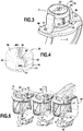
- this rotation guiding device 14 consists of a rotor 24 and a stator 26, ci being arranged between the two parts 28, 30 of the support 10.
- the stator 26 is secured to each of the two parts 28, 30 of the support 10 and the rotor 24, arranged to rotate around the stator 26, is integral with the optical deflection elements 6.
- the stator 26 has a cylindrical shape with a circular section, comprising two opposite parallel faces, said upper face 58 and lower face, and a lateral face 60 axially connecting the two opposite faces.
- the stator comprises orifices axially through it from the upper face 58 to the lower face, so that screwing means previously discussed and not shown allow the attachment of the stator on the one hand to the second part 30 of the support 10, by plating the stator at the bottom of the receiving cavity of this second part 30 of the support, and secondly at the first part 28 of the support 10 which is pressed against the underside of the stator.
- the stator 26 is thus clamped between the two parts 28, 30 of the support 10.
- the stator 26 is pierced at its center with a central orifice 61 to allow the passage of the cable bundle 40 for connecting the light source 8, this bundle of cables 40 coming from outside the module and passing through the second part 30 of the support. It is understood that it is important that the cable bundle 40 passes through the stator by the center, in order not to hinder the rotation of the rotor 24 around the stator 26 fixed.
- the wiring harness is connected to the second face of the first printed circuit board 34, after passing through the stator at its center, and along the first portion 28 of the support 10 in the cavity 38, so again not to hinder the rotation of the rotor.
- the rotor 24 comprises an annular portion 62 having an inside diameter greater than the outside diameter of the stator 26, so as to surround the stator 26.
- At least two fastening tabs 64 project from the annular portion 62. represented, the two fastening tabs 64 are diametrically opposed on either side of the annular portion 62.
- Each fastening tab 64 consists of a leg 66 axially extending the annular portion 62 and a finger 68 extending substantially perpendicularly a free end of said leg 66.
- the finger 68 comprises a hole or a fastening means 70 configured to cooperate with the edge 23 provided at the upper end 22 of the optical deflection elements 6. It can be provided indifferently fixing by snap, riveting or screwing.
- the rotor 24 and the stator 26 are arranged at least partly between the first portion 28 and the second portion 30 of the support 10, in particular by being housed at least partly in the receiving cavity formed in the central portion. 48 of the second portion 30 of the support 10, this cavity being sized to receive the stator 26, a portion of the rotor 24 and a portion of the first portion 28 of the support 10, these components being stacked on each other.
- the stacking of these different components requires a complementarity of form between these components.
- the diameter of the stator 26 and the thickness of the annular portion 62 of the rotor 24 are defined with respect to the dimensions of the receiving cavity.
- the stator 26 must be able to lodge in the cavity and a sufficient free space must be left in the receiving cavity between the peripheral wall of the central portion 48 defining this cavity and the lateral face 60 of the stator 26, so that the annular portion 62 of the rotor 24 can be inserted between the peripheral wall of the central portion and the side face 60 of the stator 26 and that this annular portion can rotate freely around the stator 26 inside the cavity.
- the rotor 24 In an assembled position of the various components, the rotor 24 is arranged around the stator, in the region of its annular portion 62, and it extends along the first portion 28 of the support 10, in the zone of its two legs. fixing 64 arranged diametrically opposite on either side of this first portion 28.
- the rotor 24 is secured to the optical deflection elements 6 with the two fastening lugs 64.
- the rotor 24 extends axially along the peripheral face of the first part 28 of the support 10 to the optical deflection elements 6, so that when the assembly is fixed, the first portion 28 of the support 10 is disposed within the rotor.
- the rotor 24 and the stator 26 consist of two complementary shapes allowing the rotation of the rotor 24 and associated optical deflection elements 6 around the fixed stator 26 on the support 10.
- the rotor 24 and the optical deflection elements 6 may form a single piece, monoblock in that the separation of these two parts leads to the destruction of one or the other, so that one avoids the mounting gaps between the rotor 24 and the optical deflection elements 6 which appear when these two parts are produced separately.
- the two parts of the support 10 are advantageously made so as to form heat sinks and it will be possible for this purpose to provide them in a metal material.
- the rotor 24 and / or the stator 26 may be made of a plastic material, and for example polyoxymethylene (POM) or any other material with a low coefficient of friction that allows easy rotation of the rotor around the stator.
- POM polyoxymethylene
- the rotation guiding device 14 may comprise a bearing, in particular a ball bearing, arranged between the stator 26 and the annular portion 62 of the rotor 24, to facilitate the rotation of the rotor with respect to the stator and improve the rotational guidance function.
- the different light sources 8, 54 are semiconductor sources, and preferably of the light-emitting diode type, and the associated support plates consist of printed circuit boards.
- the light source 8 is substantially aligned with the axis of rotation 4.
- the expression “substantially aligned” is understood to mean that the distance between the geometric center of the light source such as a light emitting diode and the axis of rotation 4 of the light module 2 is not greater than the dimensions of the light emitting diode.
- the light source 8 is fixed and positioned on the first outer face of the first portion 28 of the support 10, via a first printed circuit board 34.
- the light sources are fixed in the light module 2 and their light rays emitted are oriented opposite the second portion 30 of the support 10. These light sources 8, 54 may have in the light module 2 lighting functions and / or separate signaling according to their locations and the control instructions according to the conditions of the road.
- the light source 8 is arranged to emit light rays towards the reflecting face 20 of the optical deflection elements 6, while the additional light source or sources are arranged to emit inside a translucent screen 71 participating to aesthetic functions.
- the cable bundle 40 comprises a first portion 401 for connection to a control module, arranged at least partly in the second part of the support, a second intermediate portion 402, passing through the rotational guiding device 14, and a third portion 403 for connection to the light source 8.
- the first connection portion 401 is electrically connected to connectors of a control module (not shown), which can be embedded on the second part 30 of the support, or which can be arranged outside the light module, so that the first connecting portion protrudes from the second portion 30, in particular passing through an access window 52.
- a control module not shown
- the third connection portion 403 of the cable bundle is connected to the support plate 34 of the light source, and more particularly at the level of the bearing 44 in the illustrated example.
- the third connecting portion extends in a first step substantially perpendicular to the support plate 34, along the flat part 42, being pressed against the peripheral face at the rear of the light module 2, and it extends in a second time on a portion of the second inner end face 36, in the recess 38. More specifically, that part of the second inner end face 36 against which is lined the cable bundle extends from the edge of the flat part. 42 to the center of the first portion 28 of the support 10.
- the second intermediate portion 402 extends, substantially perpendicularly, in the extension of the third connecting portion 403 from the center of the first portion 28 of the support.
- the cable bundle 40 extends substantially parallel to the axis of rotation 4 of the light module, through the guide device 14 to join the second portion 30 of the support 10.
- the cable bundle 40 passes through the guide device 14, in particular in the center of the annular portion 32 of the rotor 24 and in the center of the stator 26.
- a recess can be configured axially through the first portion 28 of the support 10, and in particular substantially in the center of the latter in the extension of the passage of the cable bundle through the rotational guiding device. 14, so that the second portion and the third connecting portion extend substantially parallel.
- a sheath may advantageously be disposed on the first portion 28 of the support 10, in particular on the footprint 38. This sheath is fixed to the first portion 28 at least at the footprint 38, in particular by gluing.
- the sleeve sized to house the cable bundle, then serves to protect and guide the bundle of power cables 40 arranged against the first portion 28 of the support 10.
- this stack When this stack is performed, it is assembles the two parts of the support and the stator by clamping screws which pass through each of these components, the rotor being locked axially, in the direction of the stack, that is to say the screwing, between the bottom wall of the cavity and the inner end face 36 of the first part 28 of the support, it being understood that the diameter of the annular portion 62 of the rotor is such that it can surround the stator, and possibly an associated bearing, and such that this portion annular is in abutment against the inner end face 36 of the first portion 28 of the support. It is understood that the use of low friction material material not to be hindered in the relative rotation of the rotor relative to the first part of the support despite this stop.
- stator has a flange extending the end of the stator bearing against the inner end face 36 of the first part of the support, and that the rotor bears against this flange rather than on the support , in order to limit friction.
- the second portion 30 of the support 10 may have protrusions 72, in particular protruding from the central portion 48, diametrically opposed, and aligned to form an additional axis of rotation 74 (visible on the figure 5 ) able to cooperate with bearings (visible on the figure 5 ) which will be described below.
- the protrusions 72 may consist of cylindrical pins.
- protrusions are here produced to form an additional axis of rotation, distinct from the first axis of rotation as previously presented, around which the optical deflection elements are configured to rotate, via the actuator 12 and the 14.
- the additional rotation axis 74 enables the light module 2 to pivot and to ensure vertical movement of the light beam at the output of the light module 2.
- the rotational guiding function around the first axis of rotation by the guiding device 14 and the optimized arrangement in this context of the wire harness supplying the light source, as has just been described above, does not require the presence of these excrescences and this additional axis of rotation. It is understood that the presence of these excrescences is optional.
- this additional rotational movement is facilitated by the very precise rotation guidance around the first axis, since the rotation around this additional axis of rotation would be difficult to implement if a cant effect occurred when performing rotation around the first axis.
- the cable bundle 40 allows this rotation around the additional axis, in that it has a third portion large enough to present a set of operation may accompany the rocking of the module.
- the first portion of the wire bundle remains pressed against the first part of the support, advantageously in the housing formed by the impression, and that the second portion remains stretched along the first axis of rotation, through the rotational guiding device 14 and in particular in the center of the stator.
- the light module according to the invention participates in the formation of a lighting and / or signaling device, in that it is arranged in a housing (not shown) of motor vehicle headlamp closed by a projection glass, so as to define a housing of the module or modules according to the invention. It will be understood that a plurality of light modules may be arranged as just described to form a lighting and / or signaling device. Note that it is advantageous that the two projectors, left and right, comprises an equivalent device, with an equivalent number of light modules.
- the invention allows the realization of different combinations of functions and to widen the lighting zone.
- a transverse pivoting of at least one light module 2 allows illumination on the left or the right of the vehicle according to the traffic and road conditions.
- the device may comprise for this purpose means for detecting a driving situation, means for calculating an operation control instruction of the light module or modules 2 as a function of the information sent by these detection means.
- These control instructions allow mobility of at least one module in rotation horizontally and / or vertically so that the light beam at the output of the light module 2 that it generates can be oriented so as to cover a large lighting zone and / or signaling while respecting congestion constraints of the light device.
- the figure 5 represents a lighting and / or signaling device comprising three light modules 2 movable in rotation so as to move the portion that it generates transversely of the overall beam emitted by the lighting and / or signaling device.
- Each light module 2 is associated with a plate 76, or a platinum portion 76, which overlaps the second portion 30 of the support 10.
- the plate 76 is fixed to the housing and is configured to position the second portion 30 of the support 10 relative to the projector.
- the device comprises a single plate which covers all the light modules 2 included in the housing, but it will be understood that each light module 2 can be associated with an individual plate, independent of the other plates.
- Each of the three light modules 2 is rotatable about a rotation axis 4 which is its own, and in at least one of these light modules, this rotation is facilitated by a rotation guiding device 14 such that it comes to be described.
- An axis of rotation 4 has been represented on the figure 5 for one of the light modules 2, and advantageously, the axis of rotation specific to each light module 2 is substantially parallel to the axis of rotation of the adjacent light modules 2.
- the plate 76 participates in the rotation of the light module or around the additional axis of rotation 74 which is specific to them.
- the plate 76 is carrier of at least two receiving lugs 77, made of material with or reported and made integral with the plate.
- two receiving lugs 77 are arranged on either side of the module to form bearing receiving elements protruding from the support 10, including the protrusions 72, as described above.
- the two receiving tabs 77 each have a hook shape defining a groove 78 in which one of the protrusions 72, of said second support portion 10 is inserted.
- the grooves 78 are arranged coaxially, and the arrangement of the tabs receiver 77 and excrescences 72 defines the additional axis of rotation 74 for the light module 2, which in this embodiment is rotatable along two axes of rotation 4 and 74, distinct and non-parallel, and advantageously perpendicular to each other .
- the first axis of rotation 4 is substantially vertical and allows the horizontal rotation (in the left-right and right-left direction) of the light beam at the output of the corresponding light module 2, within the light device.
- the additional axis of rotation 74 is substantially horizontal and allows the vertical displacement (in the up-down and down-up direction) of the light beam at the output of corresponding light module 2, within the light device.
- the light module 2 may comprise a transparent screen 71 disposed on the output path of the light beam of the light module 2.
- This screen 71 is arranged to receive the rays emitted by the additional light source (s). 54.
- the screen 71 is thus intended to produce a style effect when the additional light sources 54 are turned on, without hindering the formation of a regulatory beam when the main light source 8 is turned on. It is understood that the presence of a screen 71 here has only an additional function and that the light module could, as illustrated on the Figures 1 to 3 , do not include such a screen opposite optical deflection elements 6.
- the light module 2 further comprises a control device able to formulate, on the basis of information received from vehicle state sensors, control instructions to be sent to the actuator 12 and to actuating means (not shown) responsible for the rotational movement around the additional axis of rotation 74.
- the instructions consist in controlling the angular position of the light module 2 around the axis of rotation 4 and possibly around the additional axis of rotation 74.
- the lighting function can then be directional, thanks to the actuator 12 and the actuating means specific to the rotational movement about the additional axis of rotation 74 of the light module 2.
- the rotational movements about the axis rotation 4 and around the additional axis of rotation 74 can be simultaneous and calibrated between the two axes or completely independent.
- the simultaneous rotation is possible in particular due to the rotational drive of the actuator 12 with the light module 2 when it is driven in rotation about the additional axis of rotation 74. It will be understood that when the light module 2 is rotated about the additional axis of rotation 74, the rotation along the first axis of rotation 4 is possible thanks to a configuration provided for this purpose.
- the first mode of operation consists in that the actuator 12 transmits to the output shaft 16 a rotational movement, said output shaft 16 rotating the optical deflection elements 6 about the axis of rotation 4, the rotation being guided along a path defined by the configuration of the rotation guiding device 14.
- the optical deflection elements 6 rotate about the axis of rotation 4 by an angle defined by the control instructions sent to the actuator, while that the support 10 and the light sources that it carries remain fixed.
- An angled support 80 makes the connection between the support 10 of the light source and the actuator 12, being on the one hand integral with the second part 30 of the support and on the other hand secured to a fixing support 82 of the actuator 12, by means of fixing means, here a screwing drum arranged between the bracket bracket and the mounting bracket, and traversed by a non-visible clamping screw which fixes the bracket bracket to the mounting bracket.
- fixing means here a screwing drum arranged between the bracket bracket and the mounting bracket, and traversed by a non-visible clamping screw which fixes the bracket bracket to the mounting bracket.
- the rotation of the optical deflection elements is done without being hampered by the cable bundle which remains, in its first portion and its second portion, stretched between the second portion and the first portion of the support, which are fixed during this rotation of the optical deflection elements.
- the second mode of operation consists in that actuating means, not shown on the figure 5 , are able to push on the bracket 80 in its lower part, opposite the support 10.
- This thrust on the bracket 80 causes a pivoting of the entire module around the additional axis of rotation 74.
- protrusions 72 protruding from the second portion 30 of the support 10 rotate in the fixed bearings 77 carried by the plate 76.
- the lower part of the bracket bracket rotates, causing in its rotation about the additional axis of rotation 74 the support 82 of the actuator 12, the actuator 12, the output shaft 16, the optical deflection elements 6, the rotation guiding device 14 and the different parts of the support 10.
- the second part 30 of the support 10 is also driven in rotation about the additional axis of rotation, which causes in the same rotation the rotational guiding device 14 and the first portion 28 of the support, and then the optical deflection elements and the actuator. All these components are thus taken as a single assembly integral in rotation about the additional axis of rotation 74 to achieve a vertical displacement of the light beam at the output of the light module 2.
- the foregoing description clearly explains how the invention makes it possible to achieve the objectives it has set for itself, and in particular to propose a lighting and / or mobile lighting module rotatable according to at least one axis of rotation thanks to the actuator 12, and without constraint by means of a device for guiding in rotation 14.
- the location of the guiding device 14 at one end of the optical deflection elements opposite the output shaft 16 and of the actuator 12 allows maintenance in the upper part of the optical deflection elements 6 during rotation and to better adjust the position of the light source at the focus of the optical deflection elements.
- the particular configuration of the rotation guiding device 14, namely a stack of the different components of this guiding device with different parts of the support 10 carrying the light source makes it possible to advantageously propose a compact assembly and with a minimal clearance between the different parts. of the light module 2, thus causing less vibration and premature wear of the various components.
- the reliability of the rotational movement in the guide path around the axis of rotation 4 of the light module 2 is then increased.
Abstract
Un module lumineux (2) pour véhicule automobile comprend au moins une source de lumière (8) apte à émettre des rayons lumineux, un support portant ladite source, un câble (40) d'alimentation électrique de cette source, un élément de déviation optique (6) agencé de manière à dévier les rayons lumineux émis par cette source pour former un faisceau lumineux projeté en sortie du module lumineux, et un dispositif de guidage (14) pour guider en rotation l'élément de déviation optique autour d'un axe de rotation (4), afin de déplacer transversalement le faisceau lumineux projeté. Selon l'invention, le support comporte une première partie (28), porteuse de la source de lumière, et une deuxième partie (30), entre lesquelles est intercalée au moins une partie du dispositif de guidage (14), et le câble (40) traverse le dispositif de guidage en rotation pour être connecté à ladite source de lumière.A light module (2) for a motor vehicle comprises at least one light source (8) capable of emitting light rays, a support carrying said source, a power supply cable (40) of this source, an optical deflection element (6) arranged to deflect the light rays emitted by this source to form a projected light beam at the output of the light module, and a guiding device (14) for rotating the optical deflection element about an axis rotation (4) in order to transversely move the projected light beam. According to the invention, the support comprises a first portion (28), carrying the light source, and a second part (30), between which is inserted at least a part of the guiding device (14), and the cable ( 40) passes through the rotational guiding device to be connected to said light source.
Description
L'invention a trait au domaine de l'éclairage et/ou de la signalisation, notamment pour véhicule automobile. Plus particulièrement, l'invention a trait à un module lumineux pour véhicule automobile, ainsi qu'à un dispositif d'éclairage et/ou de signalisation comprenant un tel module lumineux.The invention relates to the field of lighting and / or signaling, in particular for a motor vehicle. More particularly, the invention relates to a light module for a motor vehicle, and to a lighting and / or signaling device comprising such a light module.
Des dispositifs d'éclairage et/ou de signalisation peuvent comporter un ou plusieurs modules lumineux montés rotatifs autour d'un axe, notamment pour répondre à des problématiques d'éclairage adaptatif. Notamment, le document
On comprend que la mise en place d'éléments tournants dans un dispositif d'éclairage nécessite la prise en compte des câbles d'alimentation électriques nécessaires à l'alimentation des sources de lumière associées au dispositif d'éclairage. Il convient que, dans le cas où la source est disposée au centre du dispositif et que des câbles doivent traverser ce dispositif pour venir alimenter la source de lumière, la rotation des éléments tournants ne soit pas gênée par la présence de câbles et que cette rotation ne génère pas de dégradation de ces câbles.It is understood that the establishment of rotating elements in a lighting device requires taking into account the power supply cables needed to power the light sources associated with the lighting device. It is appropriate that, in the case where the source is arranged in the center of the device and that cables must pass through this device to feed the light source, the rotation of the rotating elements is not hindered by the presence of cables and that this rotation does not generate degradation of these cables.
L'invention a pour objectif de proposer un support porteur d'une source de lumière à l'origine du faisceau lumineux projeté en sortie du module lumineux, configuré pour autoriser l'alimentation électrique de la source de lumière sans interférer dans le mouvement de rotation d'un module lumineux rotatif. L'invention est une amélioration des dispositifs d'éclairage et/ou de signalisation pour véhicule automobile connus de l'art antérieur, notamment en ce qui concerne le guidage en rotation d'un module lumineux pour un déplacement transversal du faisceau lumineux qu'il génère et en ce qui concerne la gestion des câbles d'alimentation électrique dans un tel guidage en rotation.The object of the invention is to propose a support carrying a source of light at the origin of the light beam projected at the output of the light module, configured to allow the power supply of the light source without interfering with the rotational movement. a rotating light module. The invention is an improvement of the lighting and / or signaling devices for a motor vehicle known from the prior art, in particular with regard to the guidance in rotation of a light module for a transverse displacement of the light beam that it generates and as regards the management of power supply cables in such a rotation guidance.
Dans ce double contexte, l'invention a pour objet un module lumineux notamment pour véhicule automobile, comprenant au moins une source de lumière apte à émettre des rayons lumineux, au moins un élément support portant ladite source de lumière, au moins un câble d'alimentation électrique de ladite au moins une source lumineuse, au moins un élément de déviation optique agencé de manière à dévier les rayons lumineux émis par la au moins une source de lumière pour former un faisceau lumineux projeté en sortie du module lumineux, un dispositif de guidage pour guider en rotation l'élément de déviation optique autour d'un axe de rotation, afin de déplacer transversalement le faisceau lumineux projeté.In this dual context, the subject of the invention is a light module, in particular for a motor vehicle, comprising at least one light source capable of emitting light rays, at least one support element carrying said light source, at least one light cable. supplying said at least one light source with at least one optical deflection element arranged to deflect the light rays emitted by the at least one light source to form a projected light beam at the output of the light module, a guiding device for guiding in rotation the optical deflection element about an axis of rotation, in order to transversely move the projected light beam.
Selon l'invention, le support comporte une première partie et une deuxième partie entre lesquelles est intercalée au moins une partie du dispositif de guidage en rotation de l'élément de déviation optique. La première partie du support est porteuse de la source de lumière, que ce soit directement ou indirectement par l'intermédiaire par exemple d'une plaque de circuits imprimés fixée sur une face de cette première partie du support. Et ledit au moins un câble traverse le dispositif de guidage en rotation pour être connecté à ladite source de lumière.According to the invention, the support comprises a first portion and a second portion between which is inserted at least a portion of the rotational guiding device of the optical deflection element. The first part of the support carries the light source, whether directly or indirectly via for example a printed circuit board fixed on one side of this first part of the support. And said at least one cable passes through the rotational guiding device to be connected to said light source.
Par déplacement transversal du faisceau lumineux, on comprend que l'orientation générale du faisceau projeté en sortie du module, c'est-à-dire en direction de la scène de route en amont du véhicule, varie dans un plan perpendiculaire à l'axe de rotation de l'élément de déviation optique.By transverse displacement of the light beam, it is understood that the general orientation of the projected beam output of the module, that is to say in the direction of the road scene upstream of the vehicle, varies in a plane perpendicular to the axis of rotation of the optical deflection element.
On s'assure ainsi, au voisinage de la source de lumière, que l'élément de déviation optique peut tourner avec précision autour du premier axe de rotation, notamment grâce au dispositif de guidage, sans que cette rotation soit gênée par la présence de câbles, puisque ceux-ci s'étendent sensiblement le long du premier axe de rotation, au moins à travers le dispositif de guidage en rotation, du fait de la configuration spécifique du support.This ensures, in the vicinity of the light source, that the optical deflection element can rotate precisely around the first axis of rotation, in particular thanks to the guiding device, without this rotation being impeded by the presence of cables. since these extend substantially along the first axis of rotation, at least through the rotational guiding device, because of the specific configuration of the support.
Selon une caractéristique de l'invention, le au moins un câble, ou faisceau de câbles le cas échéant, peut être décomposé en une pluralité de portions successives, parmi lesquelles :
- une première portion de raccordement à un module de commande, agencée au moins en partie dans la deuxième partie du support, qui peut notamment être agencée de manière à venir en recouvrement de la première partie du support et du dispositif de guidage en rotation,
- une deuxième portion intermédiaire, traversant le dispositif de guidage en rotation, et
- une troisième portion de raccordement à la source de lumière.
- a first portion of connection to a control module, arranged at least partly in the second part of the support, which can in particular be arranged in order to overlap the first part of the support and the rotational guiding device,
- a second intermediate portion, passing through the rotation guiding device, and
- a third portion of connection to the light source.
Notamment, on peut prévoir que le faisceau de câbles traverse le dispositif de guidage en rotation sensiblement au centre de celui-ci, ou en d'autres termes, centré sur le premier axe de rotation.In particular, it can be provided that the wire bundle passes through the rotation guiding device substantially in the center thereof, or in other words, centered on the first axis of rotation.
L'élément de déviation optique est mobile en rotation sous l'effet d'un actionneur, qui peut notamment comporter un arbre de sortie s'étendant le long du premier axe de rotation et portant l'élément de déviation optique.The optical deflection element is rotatable under the effect of an actuator, which may include in particular an output shaft extending along the first axis of rotation and carrying the optical deflection element.
Avantageusement, l'actionneur et le dispositif de guidage en rotation sont disposés de part et d'autre de l'élément de déviation optique le long du premier axe de rotation. On comprend que l'on évite ainsi un agencement en porte-à-faux, dans lequel la partie de l'élément de déviation optique à l'opposé de l'actionneur aurait tendance à se décaler de l'axe de rotation.Advantageously, the actuator and the rotational guiding device are disposed on either side of the optical deflection element along the first axis of rotation. It is understood that this avoids a cantilever arrangement in which the portion of the optical deflection element opposite the actuator would tend to shift from the axis of rotation.
Selon une première série de caractéristiques, prises seules ou en combinaison, on pourra prévoir que :
- la première partie du support présente une première face porteuse de la source de lumière, une deuxième face opposée tournée vers la deuxième partie du support et une face périphérique reliant axialement la première et la deuxième face ;
- la troisième portion du faisceau de câbles est disposée le long de la deuxième face et contre la face périphérique, de sorte que le faisceau de câbles est au moins partiellement désaxé dans cette troisième portion par rapport au premier axe de rotation de l'élément de déviation optique ;
- une empreinte est agencée au moins sur la deuxième face pour loger la troisième portion du faisceau de câbles ;
- un méplat est formé axialement par usinage de la face périphérique, ledit faisceau de câble étant plaqué contre la face dudit méplat.
- the first part of the support has a first carrying face of the light source, a second opposite face facing the second part of the support and a peripheral face axially connecting the first and the second face;
- the third portion of the cable bundle is arranged along the second face and against the peripheral face, so that the cable bundle is at least partially offset in this third portion relative to the first axis of rotation of the deflection element optical;
- an impression is arranged at least on the second face to accommodate the third portion of the cable bundle;
- a flat is formed axially by machining the peripheral face, said cable bundle being pressed against the face of said flat.
Dans le cas où la source de lumière est portée indirectement par la première partie du support, une plaque de support de la source de lumière, et le cas échéant une plaque de circuits imprimés associée à une diode électroluminescente formant la source de lumière, présente une première face porteuse de la source de lumière et une deuxième face disposée contre la première face de la première partie du support, ledit faisceau de câbles étant connecté sur une deuxième face opposée de la plaque de support.In the case where the light source is carried indirectly by the first part of the support, a support plate of the light source, and if necessary a printed circuit board associated with a light-emitting diode forming the light source, has a first carrying face of the light source and a second face disposed against the first face of the first portion of the support, said wiring harness being connected to a second opposite face of the support plate.
Selon une caractéristique de l'invention, le module peut comporter un fourreau de guidage du faisceau de câbles fixé sur la première partie du support. Ce fourreau pourra notamment être fixé sur la première partie du support au moins au niveau de l'empreinte.According to a characteristic of the invention, the module may comprise a guide sleeve of the cable bundle fixed on the first part of the support. This sleeve may in particular be fixed on the first part of the support at least at the level of the impression.
En outre l'invention possède au moins l'une des caractéristiques suivantes, considérées isolément ou en combinaison :
- la première partie du support et/ou la deuxième partie du support est réalisé en un matériau métallique conducteur de chaleur, notamment en aluminium ;
- le dispositif de guidage en rotation consiste en un stator solidaire de la deuxième partie du support et en un rotor solidaire des éléments de déviation optique et configuré pour tourner autour du stator ;
- le rotor et/ou le stator peuvent être réalisés en un matériau plastique ;
- le stator présente une forme cylindrique à section circulaire ;
- le rotor présente une portion annulaire dimensionnée pour entourer ledit stator ;
- le rotor comporte au moins deux pattes de fixation à l'élément de déviation optique disposées en saillie de ladite portion annulaire ; de préférence, les deux pattes de fixation sont diamétralement opposées ;
- chaque patte de fixation peut comporter une jambe prolongeant axialement la portion annulaire de guidage et un doigt prolongeant sensiblement perpendiculairement l'extrémité libre de ladite jambe ;
- la patte de fixation est rendue solidaire de l'élément de déviation optique, notamment par bouterollage, vissage ou soudage ;
- le dispositif de guidage en rotation peut comporter un roulement à billes, agencé entre le rotor et le stator ;
- le stator est enserré entre les deux parties du support ;
- le stator peut comporter des moyens de fixation communs aux deux parties du support et au stator, notamment des vis de serrage ;
- la première partie du support présente une face externe tournée à l'opposé du stator et de la deuxième partie du support, ladite source de lumière étant portée sur ladite face externe ;
- au moins le stator est percé axialement pour laisser le passage à des câbles d'alimentation de la source de lumière ; on pourra prévoir en outre que l'une et/ou l'autre des parties du support sont également percées ;
- la deuxième partie du support présente une cavité de réception du stator et de la première partie du support ; le stator et la portion annulaire du rotor peuvent être escamotés dans ladite cavité.
- the first part of the support and / or the second part of the support is made of a heat-conducting metal material, in particular aluminum;
- the rotation guiding device consists of a stator secured to the second part of the support and a rotor integral with the optical deflection elements and configured to rotate around the stator;
- the rotor and / or the stator may be made of a plastic material;
- the stator has a cylindrical shape with circular section;
- the rotor has an annular portion sized to surround said stator;
- the rotor comprises at least two fastening tabs to the optical deflection element arranged projecting from said annular portion; preferably, the two fixing lugs are diametrically opposed;
- each fixing lug may comprise a leg axially extending the annular guide portion and a finger extending substantially perpendicularly to the free end of said leg;
- the fixing lug is made integral with the optical deflection element, in particular by pegging, screwing or welding;
- the rotational guiding device may comprise a ball bearing, arranged between the rotor and the stator;
- the stator is sandwiched between the two parts of the support;
- the stator may comprise fastening means common to both parts of the support and to the stator, in particular clamping screws;
- the first part of the support has an outer face turned away from the stator and the second part of the support, said light source being carried on said outer face;
- at least the stator is pierced axially to allow passage to power cables of the light source; it can further be provided that one and / or the other parts of the support are also pierced;
- the second part of the support has a cavity for receiving the stator and the first part of the support; the stator and the annular portion of the rotor can be retracted into said cavity.
L'élément de déviation optique peut consister en un réflecteur de forme sensiblement elliptique, la source de lumière étant disposée sensiblement au voisinage d'un premier foyer dudit réflecteur.The optical deflection element may consist of a reflector of substantially elliptical shape, the light source being disposed substantially in the vicinity of a first focus of said reflector.
Selon une caractéristique de l'invention, l'élément de déviation optique peut par ailleurs être monté mobile en rotation autour d'un deuxième axe de rotation sensiblement perpendiculaire au premier axe de rotation pour déplacer dans une autre direction que la direction transversale précédemment décrite, par exemple dans une direction verticale, le faisceau lumineux correspondant en sortie du module lumineux. De préférence, le deuxième axe de rotation est porté par la deuxième partie du support associé au module lumineux.According to a characteristic of the invention, the optical deflection element can also be rotatably mounted about a second axis of rotation substantially perpendicular to the first axis of rotation to move in another direction than the transverse direction previously described, for example in a vertical direction, the corresponding light beam at the output of the light module. Preferably, the second axis of rotation is carried by the second part of the support associated with the light module.
Selon une autre série de caractéristiques, prises seules ou en combinaison avec les caractéristiques qui précèdent, propres à la source de lumière, on pourra prévoir que :
- la source de lumière comprend au moins un élément émissif à semi-conducteur ;
- la source de lumière est une diode électroluminescente ;
- le module comprend un substrat de connexion électrique apte à alimenter électriquement la source de lumière ;
- le substrat de connexion est une carte de circuit imprimé, une carte de circuit imprimé flexible ou un dispositif d'interconnexion à géométrie variable ;
- la source lumineuse est agencée sur le substrat de connexion électrique.
- the light source comprises at least one semiconductor emissive element;
- the light source is a light emitting diode;
- the module comprises an electrical connection substrate adapted to electrically power the light source;
- the connection substrate is a printed circuit board, a flexible printed circuit board or a variable geometry interconnection device;
- the light source is arranged on the electrical connection substrate.
L'invention porte également sur un dispositif d'éclairage et/ou de signalisation comprenant au moins un module lumineux tel qu'il vient d'être présenté précédemment. Le dispositif peut comporter notamment un boîtier définissant avec une glace de fermeture un logement de réception d'au moins un module lumineux. Le faisceau lumineux projeté en sortie de module lumineux est configuré pour traverser cette glace de fermeture avant d'être projeté sur la scène de route en amont du véhicule. De préférence, ce dispositif d'éclairage et/ou de signalisation comprend trois modules lumineux selon l'invention. Notamment dans ce cas, et dès lors que l'on a plusieurs modules lumineux agencés dans un dispositif lumineux commun, les faisceaux lumineux projetés par chacun des modules sont configurés pour former un faisceau lumineux global, répondant notamment à des normes règlementaires d'éclairage et/ou de signalisation de véhicule automobile.The invention also relates to a lighting and / or signaling device comprising at least one light module as just presented above. The device may comprise in particular a housing defining with a closing window a housing for receiving at least one light module. The light beam projected at the output of the light module is configured to pass through this closing window before being projected onto the road stage upstream of the vehicle. Preferably, this lighting and / or signaling device comprises three light modules according to the invention. Especially in this case, and since there are several light modules arranged in a common light device, the light beams projected by each of the modules are configured to form a global light beam, in particular meeting regulatory standards of lighting and / or signaling of a motor vehicle.
D'autres caractéristiques et avantages de la présente invention apparaîtront plus clairement à l'aide de la description et des dessins parmi lesquels :
- la
figure 1 est une vue en perspective de trois quart avant d'un module lumineux, selon un mode de réalisation de l'invention ; - la
figure 2 est une vue éclatée en perspective du module lumineux représenté sur lafigure 1 ; - la
figure 3 est une vue en perspective de trois quarts arrière du module lumineux représenté sur lafigure 1 , une partie venant en recouvrement du module dans lafigure 1 étant ici non représentée pour faciliter la lecture de la figure ; - la
figure 4 est une vue en perspective d'un détail du module lumineux représenté sur lafigure 3 ; et - la
figure 5 est une vue en perspective de trois quart avant d'un dispositif d'éclairage et/ou de signalisation comportant un ensemble de trois modules lumineux selon le mode de réalisation de l'invention représenté sur lesfigures 1 à 4 .
- the
figure 1 is a perspective view of three quarters before a light module, according to one embodiment of the invention; - the
figure 2 is an exploded view in perspective of the light module represented on thefigure 1 ; - the
figure 3 is a perspective view of three quarters rear of the light module shown on thefigure 1 , a part coming to cover the module in thefigure 1 being here not shown to facilitate the reading of the figure; - the
figure 4 is a perspective view of a detail of the light module shown on thefigure 3 ; and - the
figure 5 is a three-quarter perspective view of a lighting and / or signaling device comprising a set of three light modules according to the embodiment of the invention shown in FIGS.Figures 1 to 4 .
Dans la description qui va suivre, on adoptera à titre non limitatif une orientation longitudinale, verticale et transversale selon l'orientation traditionnellement utilisée dans l'automobile. De plus, les termes inférieur et supérieur doivent être interprétés lorsque l'objet est en position normale d'utilisation.In the following description, a longitudinal, vertical and transverse orientation will be adopted in a nonlimiting manner according to the orientation conventionally used in the automobile. In addition, the lower and upper terms must be interpreted when the object is in the normal position of use.
Les
Ce module lumineux 2 comprend au moins un élément de déviation optique 6 de rayons émis par une source de lumière 8 portée par un support 10. Le ou les éléments de déviation optique 6 sont agencés autour de l'axe de rotation 4 et ils sont entrainés en rotation par un actionneur 12 autour de l'axe de rotation 4 pour déplacer transversalement un faisceau lumineux correspondant en sortie du module lumineux 2.This
Les éléments de déviation optique 6 coopèrent avec le support 10 venant en recouvrement du module lumineux 2, notamment par l'intermédiaire d'un dispositif de guidage en rotation 14 (notamment visibles sur la
Des moyens de commande (ici non représentés) pilotent l'actionneur 12. Un mouvement est transmis par cet actionneur 12 à un arbre de sortie 16, qui transmet aux éléments de déviation optique 6 le mouvement de rotation commandé autour de l'axe de rotation 4. Tel que représenté, l'arbre de sortie 16 est rendu solidaire des éléments de déviation optique 6 au niveau d'une première extrémité 18, ici considérée comme inférieure par rapport à l'orientation définie précédemment.Control means (here not shown) drive the
Les éléments de déviation optique 6 consistent ici en un réflecteur elliptique ou parabolique, avec une face réfléchissante 20 configurée pour réfléchir les rayons de lumière émis par la source de lumière 8, qui est sensiblement disposée au voisinage d'un premier foyer des éléments de déviation optique 6. Un faisceau lumineux est ainsi généré pour former un faisceau réglementaire du point de vue de l'éclairage et/ou de la signalisation d'un véhicule automobile.The
On notera que sans sortir du contexte de l'invention, les éléments de déviation optique 6 peuvent prendre différentes formes dès lors qu'ils sont entraînés en rotation par un actionneur 12 à une première extrémité relativement à l'axe de rotation 4 et que leur agencement par rapport à la source de lumière permet de former un faisceau réglementaire.Note that without departing from the context of the invention, the
Au voisinage d'une deuxième extrémité 22 des éléments de déviation optique 6, ici l'extrémité désignée supérieure selon l'orientation décrite précédemment, c'est-à-dire à l'extrémité opposée à la première extrémité 18 où s'étend l'actionneur 12, sont disposés le dispositif de guidage en rotation 14 par l'intermédiaire desquels les éléments de déviation optique 6 coopèrent avec le support 10.In the vicinity of a
Notamment afin de permettre la fixation d'une partie de ce dispositif de guidage en rotation 14 sur les éléments de déviation optique 6, on prévoit à la deuxième extrémité 22 un bord 23 qui forme, à la périphérie de la face réfléchissante 20, une surface d'appui pour cette partie du dispositif de guidage en rotation.In particular, in order to allow part of this
On comprend que la disposition du dispositif de guidage en rotation 14 et des moyens d'entraînement que forment l'actionneur 12 et l'arbre de sortie 16, de part et d'autre des éléments de déviation optique 6, permet un guidage optimal en rotation des éléments de déviation optique autour de l'axe de rotation.It will be understood that the arrangement of the
Le dispositif de guidage en rotation 14 et l'arbre de sortie 16 rendent aptes les éléments de déviation optique 6 à effectuer une rotation allant jusqu'à 360 degrés autour du premier axe de rotation 4, sensiblement vertical, sans effort sur l'actionneur 12, et avec une grande précision dans le positionnement relatif des éléments de déviation optique 6 et de la source de lumière 8, avantageusement centrée sur l'axe de rotation 4.The
On va maintenant décrire plus en détails le support 10 et le dispositif de guidage en rotation 14, tels qu'ils viennent d'être présentés, notamment en se référant à la
Le support 10 est formé de deux parties entre lesquelles sont agencés le dispositif de guidage en rotation 14 qui eux comportent un rotor 24 et un stator 26, l'un solidaire des éléments de déviation optique 6 et l'autre solidaire du support 10.The
Le support 10 comporte une première partie 28 et une deuxième partie 30 qui peuvent former des dissipateurs thermiques réalisés en un matériau métallique conducteur de chaleur, notamment en aluminium. Ces deux parties du support 10 sont aptes à porter le dispositif de guidage en rotation 14 et/ou la ou des sources de lumière.The
La première partie 28 du support 10 présente une forme sensiblement cylindrique avec un diamètre défini et une épaisseur non nulle, ses dimensions étant définies pour autoriser une coopération et une complémentarité de forme avec une partie du dispositif de guidage 14 et la deuxième partie 30 du support 10, telle que décrit ci-après.The
La première partie 28 du support 10, telle que notamment représentée sur la
Par ailleurs, tel que cela est notamment visible sur les
Le méplat 42 est réalisé axialement par découpe sur toute la hauteur de la face périphérique 32 depuis la face d'extrémité interne 36 jusqu'à la face d'extrémité externe, laissant dégagée une partie de la plaque de support 34, de sorte qu'un palier 44 est formé entre le méplat 42 et un bord périphérique 46 de la plaque de support 34. On génère ainsi un emplacement libre pour réaliser la connexion entre l'extrémité des câbles du faisceau et la plaque de support.The
La deuxième partie 30 du support 10 vient en recouvrement du module lumineux 2, notamment des éléments de déviation optique 6 et de la première partie 28 du support 10. Cette deuxième partie 30 du support 10 comporte principalement une portion centrale 48 et une ou plusieurs portions périphériques 49 qui prolongent latéralement ladite portion centrale 48.The
La portion centrale 48 présente la forme d'une cuvette comportant une paroi de fond et une paroi périphérique qui prolonge sensiblement perpendiculairement la paroi de fond sur tout le pourtour de celle-ci. La portion centrale 48 présente sensiblement une forme cylindrique de section circulaire. Tel que cela sera décrit plus en détails ci-après, la deuxième partie 30 est orientée par rapport à la première partie 28 de sorte que la cavité formée à l'intérieur de la cuvette est tournée vers la première partie, de manière à former un logement pour cette première partie 28 et le dispositif de guidage en rotation.The
En d'autres termes, la portion centrale 48 consiste en une cavité de réception d'une partie des composants du module lumineux 2, notamment d'une partie du dispositif de guidage en rotation 14 et de la première partie 28 du support 10. Les dimensions de cette cavité de réception dépendront des dimensions des composants qu'elle doit loger.In other words, the
Par ailleurs, la paroi de fond de la portion centrale 48 est percé de deux orifices 50 traversants permettant le passage de moyens de vissage, ici non représentés, pour la fixation de cette deuxième partie 30 du support 10 à au moins une partie du dispositif de guidage en rotation 14. On pourra prévoir que les moyens de vissage passant par ces orifices traversants 50 permettent en outre la fixation de la deuxième partie 30 avec la première partie 28 du support 10.Moreover, the bottom wall of the
La deuxième partie 30 du support 10 présente au moins une fenêtre 52 d'accès à l'intérieur de la cavité formant logement pour le dispositif de guidage en rotation et la première partie 28 du support 10. Ces fenêtres permettent le passage du faisceau de câbles tel qu'il va être décrit ci-après pour l'alimentation des sources de lumière tout en permettant d'alléger la deuxième partie 30 du support 10.The
La portion périphérique prend la forme d'un plateau qui s'étend dans un prolongement sensiblement perpendiculaire de la paroi périphérique de la portion centrale 48. Au moins une partie de cette portion périphérique s'étend vers l'avant du véhicule lorsque le module lumineux 2 est mis en place dans le véhicule. Ledit plateau 49 est sensiblement plan et perpendiculaire à l'axe de rotation 4 et il porte au moins une source de lumière additionnelle 54 sur sa face inférieure, c'est-à-dire la face en regard des éléments de déviation optique 6. On comprendra que la longueur du plateau 49 devra autoriser la disposition de cette source de lumière additionnelle de sorte qu'elle soit décalée transversalement par rapport à l'axe de rotation 4. La face inférieure du plateau 49 pourra recevoir une deuxième plaque de circuits imprimés 56 sur laquelle est disposée la source de lumière additionnelle 54.The peripheral portion takes the form of a plate which extends in a substantially perpendicular extension of the peripheral wall of the
Nous allons maintenant décrire plus précisément le dispositif de guidage en rotation 14 autour de l'axe de rotation 4 du module lumineux 2. Tel que précisé précédemment, ce dispositif de guidage en rotation 14 consiste en un rotor 24 et un stator 26, ceux-ci étant agencés entre les deux parties 28, 30 du support 10.We will now describe more precisely the
Le stator 26 est solidaire de chacune des deux parties 28, 30 du support 10 et le rotor 24, agencé pour tourner autour du stator 26, est solidaire des éléments de déviation optique 6.The
Le stator 26 présente une forme cylindrique à section circulaire, comprenant deux faces parallèles opposées, dites face supérieure 58 et face inférieure, et une face latérale 60 reliant axialement les deux faces opposées. Le stator comprend des orifices traversants axialement celui-ci depuis la face supérieure 58 jusqu'à la face inférieure, de sorte que des moyens de vissage évoqués précédemment et non représentés permettent la fixation du stator d'une part à la deuxième partie 30 du support 10, en plaquant le stator au fond de la cavité de réception de cette deuxième partie 30 du support, et d'autre part à la première partie 28 du support 10 qui est plaquée contre la face inférieure du stator.The
Le stator 26 est ainsi enserré entre les deux parties 28, 30 du support 10.The
Le stator 26 est percé en son centre d'un orifice central 61 pour permettre le passage du faisceau de câbles 40 de connexion de la source de lumière 8, ce faisceau de câbles 40 provenant de l'extérieur du module et traversant au préalable la deuxième partie 30 du support. On comprend qu'il importe que le faisceau de câbles 40 traverse le stator par le centre, afin de pas gêner la rotation du rotor 24 autour du stator 26 fixe. Le faisceau de câbles est connecté sur la deuxième face de la première plaque de circuits imprimés 34, après avoir traversé le stator en son centre, et avoir longé la première partie 28 du support 10 dans l'empreinte 38, afin là encore de ne pas gêner la rotation du rotor.The
Le rotor 24 comporte une portion annulaire 62 d'un diamètre intérieur supérieur au diamètre extérieur du stator 26, de manière à venir entourer le stator 26. Au moins deux pattes de fixation 64 s'étendent en saillie de la portion annulaire 62. Tel que représenté, les deux pattes de fixations 64 sont diamétralement opposées de part et d'autre de la portion annulaire 62. Chaque patte de fixation 64 consiste en une jambe 66 prolongeant axialement la portion annulaire 62 et en un doigt 68 prolongeant sensiblement perpendiculairement une extrémité libre de ladite jambe 66. Le doigt 68 comprend un orifice ou un moyen de fixation 70 configuré pour coopérer avec le bord 23 prévu à l'extrémité supérieure 22 des éléments de déviation optique 6. On pourra prévoir indifféremment une fixation par bouterollage, rivetage ou encore par vissage.The
Nous allons maintenant décrire, plus en détails, la disposition du dispositif de guidage en rotation 14 et du support 10 dans le module lumineux 2.We will now describe, in more detail, the arrangement of the
Tel que décrit précédemment, le rotor 24 et le stator 26 sont agencés au moins en partie entre la première partie 28 et la deuxième partie 30 du support 10, notamment en étant logés au moins en partie dans la cavité de réception aménagée dans la portion centrale 48 de la deuxième partie 30 du support 10, cette cavité étant dimensionnée pour recevoir le stator 26, une partie du rotor 24 et une partie de la première partie 28 du support 10, ces composants étant empilés les uns sur les autres.As described above, the
L'empilement de ces différents composants nécessite une complémentarité de forme entre ces composants. Le diamètre du stator 26 et l'épaisseur de la portion annulaire 62 du rotor 24 sont définis par rapport aux dimensions de la cavité de réception. Le stator 26 doit pouvoir loger dans la cavité et un espace libre suffisant doit être laissé dans la cavité de réception entre la paroi périphérique de la portion centrale 48 définissant cette cavité et la face latérale 60 du stator 26, pour que la portion annulaire 62 du rotor 24 puisse être insérée entre la paroi périphérique de la portion centrale et la face latérale 60 du stator 26 et que cette portion annulaire puisse tourner librement autour du stator 26 à l'intérieur de la cavité.The stacking of these different components requires a complementarity of form between these components. The diameter of the
Dans une position assemblée des différents composants, le rotor 24 est agencé autour du stator, dans la zone de sa portion annulaire 62, et il s'étend le long de la première partie 28 du support 10, dans la zone de ses deux pattes de fixation 64 disposées de façon diamétralement opposée de part et d'autre de cette première partie 28. Le rotor 24 est rendu solidaire des éléments de déviation optique 6 à l'aide des deux pattes de fixation 64. Le rotor 24 s'étend axialement le long de la face périphérique de la première partie 28 du support 10 jusqu'aux éléments de déviation optique 6, de sorte que lorsque l'ensemble est fixé, la première partie 28 du support 10 est disposé à l'intérieur du rotor.In an assembled position of the various components, the
On comprend que, lorsque l'ensemble est monté, le rotor 24 et le stator 26 consistent en deux formes complémentaires autorisant la rotation du rotor 24 et des éléments de déviation optique 6 associés autour du stator 26 fixe sur le support 10. Dans une variante de réalisation non représentée, le rotor 24 et les éléments de déviation optique 6 peuvent former une seule pièce, monobloc en ce que la séparation de ces deux parties entraîne la destruction de l'une ou de l'autre, de sorte que l'on évite les jeux de montage entre le rotor 24 et les éléments de déviation optique 6 qui apparaissent lorsque ces deux pièces sont réalisées séparément.It is understood that, when the assembly is mounted, the
Il a été précisé précédemment que les deux parties du support 10 sont avantageusement réalisés de manière à former des dissipateurs thermiques et on pourra à cet effet prévoir de les réaliser en un matériau métallique. Le rotor 24 et/ou le stator 26 peuvent être réalisés en un matériau plastique, et à titre d'exemple du polyoxyméthylène (POM) ou tout autre matériau avec un faible coefficient de frottement qui permet une rotation aisée du rotor autour du stator.It has been stated previously that the two parts of the
Selon une autre variante de réalisation, également non représentée, le dispositif de guidage en rotation 14 peut comporter un roulement, notamment à billes, agencé entre le stator 26 et la portion annulaire 62 du rotor 24, pour faciliter la rotation du rotor par rapport au stator et améliorer la fonction de guidage en rotation.According to another variant embodiment, also not shown, the
Les différentes sources de lumière 8, 54 sont des sources à semi-conducteur, et de préférence du type diodes électroluminescentes et les plaques de support associées consistent en des plaques de circuit imprimés.The
La source de lumière 8 est sensiblement alignée sur l'axe de rotation 4. On entend par l'expression " sensiblement alignée " que la distance entre le centre géométrique de la source de lumière telle qu'une diode électroluminescente et l'axe de rotation 4 du module lumineux 2 n'est pas supérieure aux dimensions de la diode électroluminescente. Tel que décrit précédemment, la source de lumière 8 est fixée et positionnée sur la première face externe de la première partie 28 du support 10, par l'intermédiaire d'une première plaque de circuits imprimés 34.The light source 8 is substantially aligned with the axis of
Les sources de lumière sont fixes dans le module lumineux 2 et leurs rayons lumineux émis sont orientés à l'opposé de la deuxième partie 30 du support 10. Ces sources de lumière 8, 54 peuvent avoir dans le module lumineux 2 des fonctions d'éclairages et/ou de signalisation distinctes suivant leurs localisations et les instructions de commande en fonctions des conditions de la route. Notamment, la source de lumière 8 est agencée pour émettre des rayons lumineux vers la face réfléchissante 20 des éléments de déviation optique 6, tandis que la ou les sources de lumière additionnelles sont agencées pour émettre à l'intérieur d'un écran 71 translucide participant à des fonctions esthétiques.The light sources are fixed in the
Nous allons maintenant décrire plus en détail l'agencement selon l'invention du faisceau de câbles 40 dans le module lumineux.We will now describe in more detail the arrangement according to the invention of the
Il est notable que le faisceau de câbles 40 comporte une première portion 401 de raccordement à un module de commande, agencée au moins en partie dans la deuxième partie du support, une deuxième portion intermédiaire 402, traversant le dispositif de guidage en rotation 14, et une troisième portion 403 de raccordement à la source de lumière 8.It is notable that the
La première portion de raccordement 401 est reliée électriquement à des connecteurs d'un module de commande (non représentés), qui peuvent être embarqués sur le deuxième partie 30 du support, ou bien qui peuvent être agencés à l'extérieur du module lumineux, de sorte que la première portion de raccordement dépasse de la deuxième partie 30 en passant notamment par une fenêtre d'accès 52.The
La troisième portion de raccordement 403 du faisceau de câbles est connectée à la plaque de support 34 de la source de lumière, et plus particulièrement au niveau du palier 44 dans l'exemple illustré. La troisième portion de raccordement s'étend dans un premier temps sensiblement perpendiculairement à la plaque de support 34, le long du méplat 42, en étant plaqué contre la face périphérique à l'arrière du module lumineux 2, et elle s'étend dans un deuxième temps sur une partie de la deuxième face d'extrémité interne 36, dans l'empreinte 38. Plus précisément, cette partie de la deuxième face d'extrémité interne 36 contre laquelle est plaqué le faisceau de câbles s'étend du bord du méplat 42 jusqu'au centre de la première partie 28 du support 10.The
La deuxième portion intermédiaire 402 s'étend, sensiblement perpendiculairement, dans le prolongement de la troisième partie 403 de raccordement depuis le centre de la première partie 28 du support. De la sorte, le faisceau de câbles 40 s'étend sensiblement parallèlement à l'axe de rotation 4 du module lumineux, en traversant le dispositif de guidage 14 pour rejoindre la deuxième partie 30 du support 10. Le faisceau de câbles 40 traverse le dispositif de guidage 14, notamment au centre de la portion annulaire 32 du rotor 24 et au centre du stator 26.The second
Cet aménagement réalisé dans la première partie 28 du support 10, pour faire passer le faisceau de câbles 40 à travers le dispositif de guidage 14, autorise le pivotement jusqu'à 360 degrés des éléments de déviation optique 6 autour de l'axe de rotation 4 sans gêne du fait que le faisceau de câbles 40 traverse le support 10 par le dispositif de guidage 14. Par ailleurs, la présence d'une empreinte dans laquelle le faisceau de câbles peut être escamoté permet de ne pas créer de bossage sur la face d'extrémité interne 36 et de pouvoir amener au plus près le stator 24 contre la première partie 28 du support.This arrangement made in the
Dans une variante de réalisation non représentée, un évidement peut être configuré axialement à travers la première partie 28 du support 10, et notamment sensiblement au centre de celle-ci dans le prolongement du passage du faisceau de câbles à travers le dispositif de guidage en rotation 14, de sorte que la deuxième portion et la troisième portion de raccordement s'étendent sensiblement parallèlement.In an alternative embodiment not shown, a recess can be configured axially through the
Un fourreau peut avantageusement être disposé sur la première partie 28 du support 10, notamment sur l'empreinte 38. Ce fourreau est fixé à la première partie 28 au moins au niveau de l'empreinte 38, notamment par collage. Le fourreau, dimensionné pour loger le faisceau de câbles, sert alors à protéger ainsi qu'à guider le faisceau de câbles d'alimentation 40 disposé contre la première partie 28 du support 10.A sheath may advantageously be disposed on the
On pourra monter les différentes parties du support et l'ensemble rotor-stator par exemple en retournant la deuxième partie du support et en disposant successivement dans la cavité de réception le stator, que l'on vient plaquer contre la paroi de fond de cette cavité de réception, le rotor, que l'on vient disposer autour du stator, puis la première partie 28 du support que l'on glisse entre les pattes de fixation 64 pour l'appuyer contre le stator 26. Lorsque cet empilement est effectué, on assemble les deux parties du support et le stator par des vis de serrage qui traversent chacun de ces composants, le rotor étant bloqué axialement, dans la direction de l'empilement, c'est-à-dire du vissage, entre la paroi de fond de la cavité et la face d'extrémité interne 36 de la première partie 28 du support, étant entendu que le diamètre de la portion annulaire 62 du rotor est tel qu'il peut entourer le stator, et éventuellement un roulement associé, et tel que cette portion annulaire est en butée contre la face d'extrémité interne 36 de la première partie 28 du support. On comprend que l'utilisation de matériau à faible coefficient de frottement permet de ne pas être gênée dans la rotation relative du rotor par rapport à la première partie du support malgré cette butée. On pourrait prévoir en variante que le stator présente une collerette prolongeant l'extrémité du stator venant en appui contre la face d'extrémité interne 36 de la première partie du support, et que le rotor vient en appui sur cette collerette plutôt que sur le support, afin de limiter les frottements.It is possible to mount the various parts of the support and the rotor-stator assembly, for example by inverting the second part of the support and disposing successively in the receiving cavity the stator, which is pressed against the bottom wall of this cavity. receiving, the rotor, which is just disposed around the stator, then the
Dans le mode de réalisation illustré, il peut être prévu que la deuxième partie 30 du support 10 peut présenter des excroissances 72, en saillie notamment de la portion centrale 48, diamétralement opposées, et alignées pour former un axe de rotation additionnel 74 (visible sur la
On comprendra que ces excroissances sont ici réalisées pour former un axe de rotation additionnel, distinct du premier axe de rotation tel qu'il a été présenté précédemment, autour duquel les éléments de déviation optique sont configurés pour tourner, via l'actionneur 12 et le dispositif de guidage en rotation 14. L'axe de rotation additionnel 74 permet au module lumineux 2 de pivoter et d'assurer un mouvement vertical du faisceau lumineux en sortie de module lumineux 2.It will be understood that these protrusions are here produced to form an additional axis of rotation, distinct from the first axis of rotation as previously presented, around which the optical deflection elements are configured to rotate, via the
Bien entendu, la fonction de guidage en rotation autour du premier axe de rotation par le dispositif de guidage 14 et la disposition optimisée dans ce contexte du faisceau de câbles alimentant la source lumineuse, tel que cela vient d'être décrit précédemment, ne nécessite pas la présence de ces excroissances et de cet axe de rotation additionnel. On comprend que la présence de ces excroissances est facultative. Toutefois, il est intéressant de noter que la mise en oeuvre de ce mouvement de rotation additionnel est facilité par le guidage en rotation très précis autour du premier axe, puisque la rotation autour de cet axe de rotation additionnel serait difficile à mettre en oeuvre si un effet de porte à faux se produisait lors de la réalisation de la rotation autour du premier axe. Et il convient de noter que le faisceau de câbles 40 permet cette rotation autour de l'axe additionnel, en ce qu'il présente une troisième portion suffisamment grande pour présenter un jeu de fonctionnement susceptible d'accompagner le balancement du module. Lors de la rotation autour de l'axe de rotation additionnel, il convient de noter que la première portion du faisceau de câbles reste plaquée contre la première partie du support, avantageusement dans le logement formé par l'empreinte, et que la deuxième portion reste tendue le long du premier axe de rotation, à travers le dispositif de guidage en rotation 14 et notamment au centre du stator.Of course, the rotational guiding function around the first axis of rotation by the guiding
Le module lumineux selon l'invention, tel qu'il vient d'être décrit, participe à la formation d'un dispositif d'éclairage et/ou de signalisation, en ce qu'il est disposé dans un boîtier (non représenté) de projecteur de véhicule automobile fermé par une glace de projection, de manière à définir un logement du ou des modules selon l'invention. On comprend que l'on pourra disposer une pluralité de module lumineux tel qu'ils viennent d'être décrits pour former un dispositif d'éclairage et /ou de signalisation. Notons qu'il est avantageux que les deux projecteurs, gauche et droit, comporte un dispositif équivalent, avec un nombre équivalent de modules lumineux.The light module according to the invention, as just described, participates in the formation of a lighting and / or signaling device, in that it is arranged in a housing (not shown) of motor vehicle headlamp closed by a projection glass, so as to define a housing of the module or modules according to the invention. It will be understood that a plurality of light modules may be arranged as just described to form a lighting and / or signaling device. Note that it is advantageous that the two projectors, left and right, comprises an equivalent device, with an equivalent number of light modules.
Selon des instructions de commande d'éclairage des sources de lumière et selon des instructions de commande en rotation du module lumineux 2, l'invention permet la réalisation de différentes combinaisons de fonctions et d'élargir la zone d'éclairage. Un pivotement transversal d'au moins un module lumineux 2 permet un éclairage sur la gauche ou la droite du véhicule en fonction des conditions de circulation et de route.According to lighting control instructions of the light sources and according to instructions for rotating the
Le dispositif peut comporter à cet effet des moyens de détection d'une situation de conduite, des moyens de calculs d'une instruction de commande de fonctionnement du ou des modules lumineux 2 en fonction des informations envoyées par ces moyens de détection. Ces instructions de commande permettent une mobilité d'au moins un module en rotation horizontalement et/ou verticalement de sorte que le faisceau lumineux en sortie de module lumineux 2 qu'il génère puisse être orienté de façon à couvrir une grande zone d'éclairage et/ou de signalisation tout en respectant des contraintes d'encombrement du dispositif lumineux.The device may comprise for this purpose means for detecting a driving situation, means for calculating an operation control instruction of the light module or
La
Chaque module lumineux 2 est associé à une platine 76, ou une portion de platine 76, qui vient en recouvrement de la deuxième partie 30 du support 10. La platine 76 est fixée au boîtier et elle est configurée pour positionner la deuxième partie 30 du support 10 par rapport au projecteur.Each
Tel que représenté sur la
Chacun des trois modules lumineux 2 est mobile en rotation autour d'un axe de rotation 4 qui lui est propre, et dans au moins un de ces modules lumineux, cette rotation est facilitée par un dispositif de guidage en rotation 14 tels qu'il vient d'être décrit. Un axe de rotation 4 a été représenté sur la
Dans l'exemple d'application illustré, la platine 76 participe à la mise en rotation du ou des module lumineux autour de l'axe de rotation additionnel 74 qui leur est propre. A cet effet, la platine 76 est porteuse d'au moins deux pattes de réception 77, venues de matière avec ou rapportées et rendues solidaires de la platine. Pour un module lumineux donné, deux pattes de réception 77 sont agencées de part et d'autre du module pour former des paliers de réception d'éléments en saillie du support 10, notamment les excroissances 72, telles que décrites précédemment. Les deux pattes de réception 77 présentent chacune une forme en crochet définissant une gorge 78 dans laquelle s'insère une des excroissances 72, de ladite deuxième partie 30 de support 10. Les gorges 78 sont agencées de façon coaxiale, et l'agencement des pattes de réception 77 et des excroissances 72 définit l'axe de rotation additionnel 74 pour le module lumineux 2, qui dans ce mode réalisation, est mobile en rotation suivant deux axes de rotations 4 et 74, distincts et non parallèles, et avantageusement perpendiculaires entre eux.In the illustrated example of application, the
Dans une configuration donnée, le premier axe de rotation 4 est sensiblement vertical et permet la rotation horizontale (dans le sens gauche-droite et droite-gauche) du faisceau lumineux en sortie du module lumineux 2 correspondant, au sein du dispositif lumineux. L'axe de rotation additionnel 74 est sensiblement horizontal et permet le déplacement vertical (dans le sens haut-bas et bas-haut) du faisceau lumineux en sortie de module lumineux 2 correspondant, au sein du dispositif lumineux.In a given configuration, the first axis of
Tel que cela est visible sur la
Le module lumineux 2 comporte en outre un dispositif de commande apte à formuler, sur la base d'informations reçues en provenance de capteurs d'état du véhicule des instructions de commande à envoyer à l'actionneur 12 et à des moyens d'actionnement (non représentés) responsable du mouvement de rotation autour de l'axe de rotation additionnel 74. Les instructions consistent à piloter la position angulaire du module lumineux 2 autour de l'axe de rotation 4 et éventuellement autour de l'axe de rotation additionnel 74.The
La fonction d'éclairage peut alors être directionnelle, grâce à l'actionneur 12 et aux moyens d'actionnements propres au mouvement de rotation autour de l'axe de rotation additionnel 74 du module lumineux 2. Les mouvements de rotation autour de l'axe de rotation 4 et autour de l'axe de rotation additionnel 74 peuvent être simultanés et calibrés entre les deux axes ou totalement indépendants.The lighting function can then be directional, thanks to the
La rotation simultanée est notamment possible du fait de l'entrainement en rotation de l'actionneur 12 avec le module lumineux 2 lorsque celui-ci est entrainé en rotation autour de l'axe de rotation additionnel 74. On comprendra que lorsque le module lumineux 2 est entrainé en rotation autour de l'axe de rotation additionnel 74, la rotation selon le premier axe de rotation 4 est possible notamment grâce à une configuration prévue à cet effet.The simultaneous rotation is possible in particular due to the rotational drive of the
Nous allons décrire maintenant le fonctionnement du dispositif lumineux, et notamment un premier mode dans lequel le faisceau lumineux en sortie de module lumineux 2 est décalé horizontalement, et un deuxième mode dans lequel le faisceau lumineux en sortie de module lumineux est décalé verticalement. Ces deux modes de fonctionnement peuvent fonctionner simultanément ou alternativement.We will now describe the operation of the light device, and in particular a first mode in which the light beam at the output of
Le premier mode de fonctionnement consiste en ce que l'actionneur 12 transmet à l'arbre de sortie 16 un mouvement de rotation, ledit arbre de sortie 16 entrainant en rotation les éléments de déviation optique 6 autour de l'axe de rotation 4, la rotation étant guidée selon un chemin défini par la configuration du dispositif de guidage en rotation 14. Les éléments de déviation optique 6 tournent autour de l'axe de rotation 4 d'un angle défini par les instructions de commande envoyées à l'actionneur, tandis que le support 10 et les sources de lumière qu'il porte restent fixes. Un support équerre 80 fait le lien entre le support 10 de la source de lumière et l'actionneur 12, en étant d'une part solidaire de la deuxième partie 30 du support et d'autre part solidaire d'un support de fixation 82 de l'actionneur 12, grâce à des moyens de fixation, ici un fût de vissage agencé entre le support équerre et le support de fixation, et traversé par une vis de serrage non visible qui fixe le support équerre sur le support de fixation. Ce support équerre reste fixe pendant la rotation des éléments de déviation optique autour de l'axe de rotation 4. Cette rotation des éléments de déviation optique autour de l'axe de rotation 4 génère un déplacement des rayons émis par la source de lumière 8 de sorte que l'on peut générer un mouvement transversal du faisceau en sortie du dispositif d'éclairage et/ou de signalisation. On comprend que, selon l'invention, la rotation des éléments de déviation optique se fait sans être gênée par le faisceau de câbles qui reste, dans sa première portion et sa deuxième portion, tendu entre la deuxième partie et la première partie du support, qui sont fixes pendant cette rotation des éléments de déviation optique.The first mode of operation consists in that the
Le deuxième mode de fonctionnement consiste en ce que des moyens d'actionnement, non représentés sur la
La description qui précède explique clairement comment l'invention permet d'atteindre les objectifs qu'elle s'est fixée et notamment de proposer un module lumineux d'éclairage et/ou de signalisation mobile en rotation selon au moins un axe de rotation grâce à l'actionneur 12, et sans contrainte grâce à un dispositif de guidage en rotation 14. Selon l'invention, la localisation du dispositif de guidage 14 à une extrémité des éléments de déviation optique à l'opposé de l'arbre de sortie 16 et de l'actionneur 12 permet un maintien en partie supérieure des éléments de déviation optique 6 lors de la rotation et d'ajuster au mieux la position de la source de lumière au foyer des éléments de déviation optique.The foregoing description clearly explains how the invention makes it possible to achieve the objectives it has set for itself, and in particular to propose a lighting and / or mobile lighting module rotatable according to at least one axis of rotation thanks to the
La configuration particulière du dispositif de guidage en rotation 14, à savoir un empilement des différents composants de ce dispositif de guidage avec différentes parties du support 10 portant la source de lumière permet de proposer avantageusement un ensemble compact et avec un jeu minime entre les différentes pièces du module lumineux 2, provoquant ainsi moins de vibrations et d'usure prématurée des différents composants. La fiabilité du mouvement de rotation dans le chemin de guidage autour de l'axe de rotation 4 du module lumineux 2 est alors augmentée.The particular configuration of the
Claims (14)
Applications Claiming Priority (1)
| Application Number | Priority Date | Filing Date | Title |
|---|---|---|---|
| FR1653832A FR3050796B1 (en) | 2016-04-28 | 2016-04-28 | ROTARY LIGHT MODULE |
Publications (2)
| Publication Number | Publication Date |
|---|---|
| EP3239598A1 true EP3239598A1 (en) | 2017-11-01 |
| EP3239598B1 EP3239598B1 (en) | 2021-10-13 |
Family
ID=56611359
Family Applications (1)
| Application Number | Title | Priority Date | Filing Date |
|---|---|---|---|
| EP17167370.0A Active EP3239598B1 (en) | 2016-04-28 | 2017-04-20 | Rotary light module |
Country Status (4)
| Country | Link |
|---|---|
| US (1) | US10260728B2 (en) |
| EP (1) | EP3239598B1 (en) |
| CN (1) | CN107339654B (en) |
| FR (1) | FR3050796B1 (en) |
Families Citing this family (2)
| Publication number | Priority date | Publication date | Assignee | Title |
|---|---|---|---|---|
| CN109931571B (en) * | 2017-12-19 | 2022-07-01 | 意大利汽车照明股份公司 | Lighting device for vehicle |
| FR3103877B1 (en) * | 2019-11-28 | 2022-07-08 | Valeo Vision | Optical element and light module of a motor vehicle equipped with such an optical element |
Citations (3)
| Publication number | Priority date | Publication date | Assignee | Title |
|---|---|---|---|---|
| US1369953A (en) * | 1919-11-06 | 1921-03-01 | Ernst Rose W | Motor-vehicle light |
| US20110019438A1 (en) * | 2009-07-24 | 2011-01-27 | Cal-Comp Electronics & Communications Company Limited | Light emitting diode lamp |
| EP2957464A1 (en) | 2014-06-16 | 2015-12-23 | Valeo Vision | Rotary lighting and/or signalling module |
Family Cites Families (4)
| Publication number | Priority date | Publication date | Assignee | Title |
|---|---|---|---|---|
| JP3910359B2 (en) * | 2000-11-24 | 2007-04-25 | 株式会社小糸製作所 | Vehicle lamp |
| US7810972B2 (en) * | 2006-10-13 | 2010-10-12 | Visteon Global Technologies, Inc. | Headlamp assembly having an adjustable light beam direction |
| JP5218115B2 (en) * | 2009-02-03 | 2013-06-26 | 市光工業株式会社 | Vehicle lighting |
| US9534756B2 (en) * | 2012-04-03 | 2017-01-03 | Sharp Kabushiki Kaisha | Light-emitting device, floodlight, and vehicle headlight |
-
2016
- 2016-04-28 FR FR1653832A patent/FR3050796B1/en not_active Expired - Fee Related
-
2017
- 2017-04-20 EP EP17167370.0A patent/EP3239598B1/en active Active
- 2017-04-25 CN CN201710280041.4A patent/CN107339654B/en active Active
- 2017-04-28 US US15/581,469 patent/US10260728B2/en not_active Expired - Fee Related
Patent Citations (3)
| Publication number | Priority date | Publication date | Assignee | Title |
|---|---|---|---|---|
| US1369953A (en) * | 1919-11-06 | 1921-03-01 | Ernst Rose W | Motor-vehicle light |
| US20110019438A1 (en) * | 2009-07-24 | 2011-01-27 | Cal-Comp Electronics & Communications Company Limited | Light emitting diode lamp |
| EP2957464A1 (en) | 2014-06-16 | 2015-12-23 | Valeo Vision | Rotary lighting and/or signalling module |
Also Published As
| Publication number | Publication date |
|---|---|
| EP3239598B1 (en) | 2021-10-13 |
| FR3050796A1 (en) | 2017-11-03 |
| US10260728B2 (en) | 2019-04-16 |
| CN107339654A (en) | 2017-11-10 |
| CN107339654B (en) | 2021-05-04 |
| US20170314755A1 (en) | 2017-11-02 |
| FR3050796B1 (en) | 2019-11-29 |
Similar Documents
| Publication | Publication Date | Title |
|---|---|---|
| EP2598793B1 (en) | Optical module of an illuminating and/or signalling device of a motor vehicle | |
| EP3238991A1 (en) | Rotary light module | |
| EP2598797B1 (en) | Optical module of an illuminating and/or signalling device of a motor vehicle | |
| EP2754949B1 (en) | Lighting module and method for mounting such a module | |
| EP2775197A1 (en) | Lighting and/or signalling device for a motor vehicle comprising a light guide | |
| EP2966343B1 (en) | Lighting module for a motor vehicle headlight with positioning means between heat sink and reflector/circuit board | |
| WO2012013591A1 (en) | Optical module of an illuminating and/or signalling device of a motor vehicle | |
| WO2016050624A1 (en) | Luminous device of vehicle with means for positioning an electronic board | |
| EP2295850A1 (en) | Lighting and/or signalling device for an automobile | |
| EP3239598B1 (en) | Rotary light module | |
| EP2957821B1 (en) | Rotary lighting and/or signalling module | |
| EP2957823B1 (en) | Rotary lighting and/or signalling module | |
| FR3049041A1 (en) | LUMINOUS MODULE COMPRISING AT LEAST ONE REMOVABLE LIGHT SOURCE | |
| EP3884206B1 (en) | Multi-functional light module provided with two flat light guides | |
| EP3238992B1 (en) | Rotary light module | |
| FR2964723A1 (en) | Optical module for lighting and signaling device such as headlight type lighting device, of motor vehicle, has reflectors that are formed on part equipped with cooling opening for circulation of cooling air | |
| FR3050798A1 (en) | ROTARY LIGHT MODULE | |
| EP3301351A1 (en) | Integral mounting for luminous device with micro-mirror array | |
| EP2772680B1 (en) | Rotary electric lighting apparatus | |
| FR3064721B1 (en) | LUMINOUS DEVICE WITH RADIATOR CROSSING THE HOUSING | |
| FR3038693A1 (en) | LUMINOUS MODULE FOR MOTOR VEHICLE PROJECTOR | |
| EP4184054A1 (en) | Safety lighting device | |
| FR2964724A1 (en) | Optical module for lighting and signaling device e.g. headlight type light projector, of motor vehicle, has folding element fixed in module in motionless manner with respect to light source, where folding element is made by metal piece | |
| FR2973477A1 (en) | Mechanism for adjusting cut of e.g. optical module of left headlight of car, has compensation device for compensating axial play of cutting unit that rotates with respect to frame, and exerting force on unit in direction of rotational axis |
Legal Events
| Date | Code | Title | Description |
|---|---|---|---|
| PUAI | Public reference made under article 153(3) epc to a published international application that has entered the european phase |
Free format text: ORIGINAL CODE: 0009012 |
|
| STAA | Information on the status of an ep patent application or granted ep patent |
Free format text: STATUS: THE APPLICATION HAS BEEN PUBLISHED |
|
| AK | Designated contracting states |
Kind code of ref document: A1 Designated state(s): AL AT BE BG CH CY CZ DE DK EE ES FI FR GB GR HR HU IE IS IT LI LT LU LV MC MK MT NL NO PL PT RO RS SE SI SK SM TR |
|
| AX | Request for extension of the european patent |
Extension state: BA ME |
|
| STAA | Information on the status of an ep patent application or granted ep patent |
Free format text: STATUS: REQUEST FOR EXAMINATION WAS MADE |
|
| 17P | Request for examination filed |
Effective date: 20180425 |
|
| RBV | Designated contracting states (corrected) |
Designated state(s): AL AT BE BG CH CY CZ DE DK EE ES FI FR GB GR HR HU IE IS IT LI LT LU LV MC MK MT NL NO PL PT RO RS SE SI SK SM TR |
|
| REG | Reference to a national code |
Ref country code: DE Ref legal event code: R079 Ref document number: 602017047454 Country of ref document: DE Free format text: PREVIOUS MAIN CLASS: F21S0008100000 Ipc: F21S0041141000 |
|
| GRAP | Despatch of communication of intention to grant a patent |
Free format text: ORIGINAL CODE: EPIDOSNIGR1 |
|
| STAA | Information on the status of an ep patent application or granted ep patent |
Free format text: STATUS: GRANT OF PATENT IS INTENDED |
|
| RIC1 | Information provided on ipc code assigned before grant |
Ipc: F21S 43/19 20180101ALI20210326BHEP Ipc: F21S 41/675 20180101ALI20210326BHEP Ipc: F21S 41/32 20180101ALI20210326BHEP Ipc: F21S 41/19 20180101ALI20210326BHEP Ipc: F21S 41/141 20180101AFI20210326BHEP |
|
| INTG | Intention to grant announced |
Effective date: 20210429 |
|
| GRAS | Grant fee paid |
Free format text: ORIGINAL CODE: EPIDOSNIGR3 |
|
| GRAA | (expected) grant |
Free format text: ORIGINAL CODE: 0009210 |
|
| STAA | Information on the status of an ep patent application or granted ep patent |
Free format text: STATUS: THE PATENT HAS BEEN GRANTED |
|
| AK | Designated contracting states |
Kind code of ref document: B1 Designated state(s): AL AT BE BG CH CY CZ DE DK EE ES FI FR GB GR HR HU IE IS IT LI LT LU LV MC MK MT NL NO PL PT RO RS SE SI SK SM TR |
|
| REG | Reference to a national code |
Ref country code: GB Ref legal event code: FG4D Free format text: NOT ENGLISH |
|
| REG | Reference to a national code |
Ref country code: CH Ref legal event code: EP |
|
| REG | Reference to a national code |
Ref country code: DE Ref legal event code: R096 Ref document number: 602017047454 Country of ref document: DE |
|
| REG | Reference to a national code |
Ref country code: IE Ref legal event code: FG4D Free format text: LANGUAGE OF EP DOCUMENT: FRENCH |
|
| REG | Reference to a national code |
Ref country code: AT Ref legal event code: REF Ref document number: 1438439 Country of ref document: AT Kind code of ref document: T Effective date: 20211115 |
|
| REG | Reference to a national code |
Ref country code: LT Ref legal event code: MG9D |
|
| REG | Reference to a national code |
Ref country code: NL Ref legal event code: MP Effective date: 20211013 |
|
| REG | Reference to a national code |
Ref country code: AT Ref legal event code: MK05 Ref document number: 1438439 Country of ref document: AT Kind code of ref document: T Effective date: 20211013 |
|
| PG25 | Lapsed in a contracting state [announced via postgrant information from national office to epo] |
Ref country code: RS Free format text: LAPSE BECAUSE OF FAILURE TO SUBMIT A TRANSLATION OF THE DESCRIPTION OR TO PAY THE FEE WITHIN THE PRESCRIBED TIME-LIMIT Effective date: 20211013 Ref country code: LT Free format text: LAPSE BECAUSE OF FAILURE TO SUBMIT A TRANSLATION OF THE DESCRIPTION OR TO PAY THE FEE WITHIN THE PRESCRIBED TIME-LIMIT Effective date: 20211013 Ref country code: FI Free format text: LAPSE BECAUSE OF FAILURE TO SUBMIT A TRANSLATION OF THE DESCRIPTION OR TO PAY THE FEE WITHIN THE PRESCRIBED TIME-LIMIT Effective date: 20211013 Ref country code: BG Free format text: LAPSE BECAUSE OF FAILURE TO SUBMIT A TRANSLATION OF THE DESCRIPTION OR TO PAY THE FEE WITHIN THE PRESCRIBED TIME-LIMIT Effective date: 20220113 Ref country code: AT Free format text: LAPSE BECAUSE OF FAILURE TO SUBMIT A TRANSLATION OF THE DESCRIPTION OR TO PAY THE FEE WITHIN THE PRESCRIBED TIME-LIMIT Effective date: 20211013 |
|
| PG25 | Lapsed in a contracting state [announced via postgrant information from national office to epo] |
Ref country code: IS Free format text: LAPSE BECAUSE OF FAILURE TO SUBMIT A TRANSLATION OF THE DESCRIPTION OR TO PAY THE FEE WITHIN THE PRESCRIBED TIME-LIMIT Effective date: 20220213 Ref country code: SE Free format text: LAPSE BECAUSE OF FAILURE TO SUBMIT A TRANSLATION OF THE DESCRIPTION OR TO PAY THE FEE WITHIN THE PRESCRIBED TIME-LIMIT Effective date: 20211013 Ref country code: PT Free format text: LAPSE BECAUSE OF FAILURE TO SUBMIT A TRANSLATION OF THE DESCRIPTION OR TO PAY THE FEE WITHIN THE PRESCRIBED TIME-LIMIT Effective date: 20220214 Ref country code: PL Free format text: LAPSE BECAUSE OF FAILURE TO SUBMIT A TRANSLATION OF THE DESCRIPTION OR TO PAY THE FEE WITHIN THE PRESCRIBED TIME-LIMIT Effective date: 20211013 Ref country code: NO Free format text: LAPSE BECAUSE OF FAILURE TO SUBMIT A TRANSLATION OF THE DESCRIPTION OR TO PAY THE FEE WITHIN THE PRESCRIBED TIME-LIMIT Effective date: 20220113 Ref country code: NL Free format text: LAPSE BECAUSE OF FAILURE TO SUBMIT A TRANSLATION OF THE DESCRIPTION OR TO PAY THE FEE WITHIN THE PRESCRIBED TIME-LIMIT Effective date: 20211013 Ref country code: LV Free format text: LAPSE BECAUSE OF FAILURE TO SUBMIT A TRANSLATION OF THE DESCRIPTION OR TO PAY THE FEE WITHIN THE PRESCRIBED TIME-LIMIT Effective date: 20211013 Ref country code: HR Free format text: LAPSE BECAUSE OF FAILURE TO SUBMIT A TRANSLATION OF THE DESCRIPTION OR TO PAY THE FEE WITHIN THE PRESCRIBED TIME-LIMIT Effective date: 20211013 Ref country code: GR Free format text: LAPSE BECAUSE OF FAILURE TO SUBMIT A TRANSLATION OF THE DESCRIPTION OR TO PAY THE FEE WITHIN THE PRESCRIBED TIME-LIMIT Effective date: 20220114 Ref country code: ES Free format text: LAPSE BECAUSE OF FAILURE TO SUBMIT A TRANSLATION OF THE DESCRIPTION OR TO PAY THE FEE WITHIN THE PRESCRIBED TIME-LIMIT Effective date: 20211013 |
|
| REG | Reference to a national code |
Ref country code: DE Ref legal event code: R097 Ref document number: 602017047454 Country of ref document: DE |
|
| PG25 | Lapsed in a contracting state [announced via postgrant information from national office to epo] |
Ref country code: SM Free format text: LAPSE BECAUSE OF FAILURE TO SUBMIT A TRANSLATION OF THE DESCRIPTION OR TO PAY THE FEE WITHIN THE PRESCRIBED TIME-LIMIT Effective date: 20211013 Ref country code: SK Free format text: LAPSE BECAUSE OF FAILURE TO SUBMIT A TRANSLATION OF THE DESCRIPTION OR TO PAY THE FEE WITHIN THE PRESCRIBED TIME-LIMIT Effective date: 20211013 Ref country code: RO Free format text: LAPSE BECAUSE OF FAILURE TO SUBMIT A TRANSLATION OF THE DESCRIPTION OR TO PAY THE FEE WITHIN THE PRESCRIBED TIME-LIMIT Effective date: 20211013 Ref country code: EE Free format text: LAPSE BECAUSE OF FAILURE TO SUBMIT A TRANSLATION OF THE DESCRIPTION OR TO PAY THE FEE WITHIN THE PRESCRIBED TIME-LIMIT Effective date: 20211013 Ref country code: DK Free format text: LAPSE BECAUSE OF FAILURE TO SUBMIT A TRANSLATION OF THE DESCRIPTION OR TO PAY THE FEE WITHIN THE PRESCRIBED TIME-LIMIT Effective date: 20211013 Ref country code: CZ Free format text: LAPSE BECAUSE OF FAILURE TO SUBMIT A TRANSLATION OF THE DESCRIPTION OR TO PAY THE FEE WITHIN THE PRESCRIBED TIME-LIMIT Effective date: 20211013 |
|
| PLBE | No opposition filed within time limit |
Free format text: ORIGINAL CODE: 0009261 |
|
| STAA | Information on the status of an ep patent application or granted ep patent |
Free format text: STATUS: NO OPPOSITION FILED WITHIN TIME LIMIT |
|
| 26N | No opposition filed |
Effective date: 20220714 |
|
| PG25 | Lapsed in a contracting state [announced via postgrant information from national office to epo] |
Ref country code: AL Free format text: LAPSE BECAUSE OF FAILURE TO SUBMIT A TRANSLATION OF THE DESCRIPTION OR TO PAY THE FEE WITHIN THE PRESCRIBED TIME-LIMIT Effective date: 20211013 |
|
| PG25 | Lapsed in a contracting state [announced via postgrant information from national office to epo] |
Ref country code: SI Free format text: LAPSE BECAUSE OF FAILURE TO SUBMIT A TRANSLATION OF THE DESCRIPTION OR TO PAY THE FEE WITHIN THE PRESCRIBED TIME-LIMIT Effective date: 20211013 |
|
| REG | Reference to a national code |
Ref country code: CH Ref legal event code: PL |
|
| GBPC | Gb: european patent ceased through non-payment of renewal fee |
Effective date: 20220420 |
|
| REG | Reference to a national code |
Ref country code: BE Ref legal event code: MM Effective date: 20220430 |
|
| PG25 | Lapsed in a contracting state [announced via postgrant information from national office to epo] |
Ref country code: MC Free format text: LAPSE BECAUSE OF FAILURE TO SUBMIT A TRANSLATION OF THE DESCRIPTION OR TO PAY THE FEE WITHIN THE PRESCRIBED TIME-LIMIT Effective date: 20211013 Ref country code: LU Free format text: LAPSE BECAUSE OF NON-PAYMENT OF DUE FEES Effective date: 20220420 Ref country code: LI Free format text: LAPSE BECAUSE OF NON-PAYMENT OF DUE FEES Effective date: 20220430 Ref country code: GB Free format text: LAPSE BECAUSE OF NON-PAYMENT OF DUE FEES Effective date: 20220420 Ref country code: CH Free format text: LAPSE BECAUSE OF NON-PAYMENT OF DUE FEES Effective date: 20220430 |
|
| PG25 | Lapsed in a contracting state [announced via postgrant information from national office to epo] |
Ref country code: BE Free format text: LAPSE BECAUSE OF NON-PAYMENT OF DUE FEES Effective date: 20220430 |
|
| PG25 | Lapsed in a contracting state [announced via postgrant information from national office to epo] |
Ref country code: IE Free format text: LAPSE BECAUSE OF NON-PAYMENT OF DUE FEES Effective date: 20220420 |
|
| PG25 | Lapsed in a contracting state [announced via postgrant information from national office to epo] |
Ref country code: IT Free format text: LAPSE BECAUSE OF FAILURE TO SUBMIT A TRANSLATION OF THE DESCRIPTION OR TO PAY THE FEE WITHIN THE PRESCRIBED TIME-LIMIT Effective date: 20211013 |
|
| P01 | Opt-out of the competence of the unified patent court (upc) registered |
Effective date: 20230528 |
|
| PGFP | Annual fee paid to national office [announced via postgrant information from national office to epo] |
Ref country code: FR Payment date: 20230425 Year of fee payment: 7 Ref country code: DE Payment date: 20230412 Year of fee payment: 7 |
|
| PG25 | Lapsed in a contracting state [announced via postgrant information from national office to epo] |
Ref country code: HU Free format text: LAPSE BECAUSE OF FAILURE TO SUBMIT A TRANSLATION OF THE DESCRIPTION OR TO PAY THE FEE WITHIN THE PRESCRIBED TIME-LIMIT; INVALID AB INITIO Effective date: 20170420 |