EP3239559A1 - Entraînement pour une machine de travail automobile et unité d'entraînement - Google Patents
Entraînement pour une machine de travail automobile et unité d'entraînement Download PDFInfo
- Publication number
- EP3239559A1 EP3239559A1 EP17165240.7A EP17165240A EP3239559A1 EP 3239559 A1 EP3239559 A1 EP 3239559A1 EP 17165240 A EP17165240 A EP 17165240A EP 3239559 A1 EP3239559 A1 EP 3239559A1
- Authority
- EP
- European Patent Office
- Prior art keywords
- drive
- transmission
- output
- drive source
- unit
- Prior art date
- Legal status (The legal status is an assumption and is not a legal conclusion. Google has not performed a legal analysis and makes no representation as to the accuracy of the status listed.)
- Granted
Links
Images


Classifications
-
- F—MECHANICAL ENGINEERING; LIGHTING; HEATING; WEAPONS; BLASTING
- F16—ENGINEERING ELEMENTS AND UNITS; GENERAL MEASURES FOR PRODUCING AND MAINTAINING EFFECTIVE FUNCTIONING OF MACHINES OR INSTALLATIONS; THERMAL INSULATION IN GENERAL
- F16H—GEARING
- F16H47/00—Combinations of mechanical gearing with fluid clutches or fluid gearing
- F16H47/02—Combinations of mechanical gearing with fluid clutches or fluid gearing the fluid gearing being of the volumetric type
-
- B—PERFORMING OPERATIONS; TRANSPORTING
- B60—VEHICLES IN GENERAL
- B60K—ARRANGEMENT OR MOUNTING OF PROPULSION UNITS OR OF TRANSMISSIONS IN VEHICLES; ARRANGEMENT OR MOUNTING OF PLURAL DIVERSE PRIME-MOVERS IN VEHICLES; AUXILIARY DRIVES FOR VEHICLES; INSTRUMENTATION OR DASHBOARDS FOR VEHICLES; ARRANGEMENTS IN CONNECTION WITH COOLING, AIR INTAKE, GAS EXHAUST OR FUEL SUPPLY OF PROPULSION UNITS IN VEHICLES
- B60K6/00—Arrangement or mounting of plural diverse prime-movers for mutual or common propulsion, e.g. hybrid propulsion systems comprising electric motors and internal combustion engines ; Control systems therefor, i.e. systems controlling two or more prime movers, or controlling one of these prime movers and any of the transmission, drive or drive units Informative references: mechanical gearings with secondary electric drive F16H3/72; arrangements for handling mechanical energy structurally associated with the dynamo-electric machine H02K7/00; machines comprising structurally interrelated motor and generator parts H02K51/00; dynamo-electric machines not otherwise provided for in H02K see H02K99/00
- B60K6/20—Arrangement or mounting of plural diverse prime-movers for mutual or common propulsion, e.g. hybrid propulsion systems comprising electric motors and internal combustion engines ; Control systems therefor, i.e. systems controlling two or more prime movers, or controlling one of these prime movers and any of the transmission, drive or drive units Informative references: mechanical gearings with secondary electric drive F16H3/72; arrangements for handling mechanical energy structurally associated with the dynamo-electric machine H02K7/00; machines comprising structurally interrelated motor and generator parts H02K51/00; dynamo-electric machines not otherwise provided for in H02K see H02K99/00 the prime-movers consisting of electric motors and internal combustion engines, e.g. HEVs
- B60K6/22—Arrangement or mounting of plural diverse prime-movers for mutual or common propulsion, e.g. hybrid propulsion systems comprising electric motors and internal combustion engines ; Control systems therefor, i.e. systems controlling two or more prime movers, or controlling one of these prime movers and any of the transmission, drive or drive units Informative references: mechanical gearings with secondary electric drive F16H3/72; arrangements for handling mechanical energy structurally associated with the dynamo-electric machine H02K7/00; machines comprising structurally interrelated motor and generator parts H02K51/00; dynamo-electric machines not otherwise provided for in H02K see H02K99/00 the prime-movers consisting of electric motors and internal combustion engines, e.g. HEVs characterised by apparatus, components or means specially adapted for HEVs
- B60K6/38—Arrangement or mounting of plural diverse prime-movers for mutual or common propulsion, e.g. hybrid propulsion systems comprising electric motors and internal combustion engines ; Control systems therefor, i.e. systems controlling two or more prime movers, or controlling one of these prime movers and any of the transmission, drive or drive units Informative references: mechanical gearings with secondary electric drive F16H3/72; arrangements for handling mechanical energy structurally associated with the dynamo-electric machine H02K7/00; machines comprising structurally interrelated motor and generator parts H02K51/00; dynamo-electric machines not otherwise provided for in H02K see H02K99/00 the prime-movers consisting of electric motors and internal combustion engines, e.g. HEVs characterised by apparatus, components or means specially adapted for HEVs characterised by the driveline clutches
- B60K6/387—Actuated clutches, i.e. clutches engaged or disengaged by electric, hydraulic or mechanical actuating means
-
- B—PERFORMING OPERATIONS; TRANSPORTING
- B60—VEHICLES IN GENERAL
- B60K—ARRANGEMENT OR MOUNTING OF PROPULSION UNITS OR OF TRANSMISSIONS IN VEHICLES; ARRANGEMENT OR MOUNTING OF PLURAL DIVERSE PRIME-MOVERS IN VEHICLES; AUXILIARY DRIVES FOR VEHICLES; INSTRUMENTATION OR DASHBOARDS FOR VEHICLES; ARRANGEMENTS IN CONNECTION WITH COOLING, AIR INTAKE, GAS EXHAUST OR FUEL SUPPLY OF PROPULSION UNITS IN VEHICLES
- B60K6/00—Arrangement or mounting of plural diverse prime-movers for mutual or common propulsion, e.g. hybrid propulsion systems comprising electric motors and internal combustion engines ; Control systems therefor, i.e. systems controlling two or more prime movers, or controlling one of these prime movers and any of the transmission, drive or drive units Informative references: mechanical gearings with secondary electric drive F16H3/72; arrangements for handling mechanical energy structurally associated with the dynamo-electric machine H02K7/00; machines comprising structurally interrelated motor and generator parts H02K51/00; dynamo-electric machines not otherwise provided for in H02K see H02K99/00
- B60K6/20—Arrangement or mounting of plural diverse prime-movers for mutual or common propulsion, e.g. hybrid propulsion systems comprising electric motors and internal combustion engines ; Control systems therefor, i.e. systems controlling two or more prime movers, or controlling one of these prime movers and any of the transmission, drive or drive units Informative references: mechanical gearings with secondary electric drive F16H3/72; arrangements for handling mechanical energy structurally associated with the dynamo-electric machine H02K7/00; machines comprising structurally interrelated motor and generator parts H02K51/00; dynamo-electric machines not otherwise provided for in H02K see H02K99/00 the prime-movers consisting of electric motors and internal combustion engines, e.g. HEVs
- B60K6/50—Architecture of the driveline characterised by arrangement or kind of transmission units
- B60K6/54—Transmission for changing ratio
- B60K6/547—Transmission for changing ratio the transmission being a stepped gearing
-
- B—PERFORMING OPERATIONS; TRANSPORTING
- B60—VEHICLES IN GENERAL
- B60K—ARRANGEMENT OR MOUNTING OF PROPULSION UNITS OR OF TRANSMISSIONS IN VEHICLES; ARRANGEMENT OR MOUNTING OF PLURAL DIVERSE PRIME-MOVERS IN VEHICLES; AUXILIARY DRIVES FOR VEHICLES; INSTRUMENTATION OR DASHBOARDS FOR VEHICLES; ARRANGEMENTS IN CONNECTION WITH COOLING, AIR INTAKE, GAS EXHAUST OR FUEL SUPPLY OF PROPULSION UNITS IN VEHICLES
- B60K6/00—Arrangement or mounting of plural diverse prime-movers for mutual or common propulsion, e.g. hybrid propulsion systems comprising electric motors and internal combustion engines ; Control systems therefor, i.e. systems controlling two or more prime movers, or controlling one of these prime movers and any of the transmission, drive or drive units Informative references: mechanical gearings with secondary electric drive F16H3/72; arrangements for handling mechanical energy structurally associated with the dynamo-electric machine H02K7/00; machines comprising structurally interrelated motor and generator parts H02K51/00; dynamo-electric machines not otherwise provided for in H02K see H02K99/00
- B60K6/20—Arrangement or mounting of plural diverse prime-movers for mutual or common propulsion, e.g. hybrid propulsion systems comprising electric motors and internal combustion engines ; Control systems therefor, i.e. systems controlling two or more prime movers, or controlling one of these prime movers and any of the transmission, drive or drive units Informative references: mechanical gearings with secondary electric drive F16H3/72; arrangements for handling mechanical energy structurally associated with the dynamo-electric machine H02K7/00; machines comprising structurally interrelated motor and generator parts H02K51/00; dynamo-electric machines not otherwise provided for in H02K see H02K99/00 the prime-movers consisting of electric motors and internal combustion engines, e.g. HEVs
- B60K6/42—Arrangement or mounting of plural diverse prime-movers for mutual or common propulsion, e.g. hybrid propulsion systems comprising electric motors and internal combustion engines ; Control systems therefor, i.e. systems controlling two or more prime movers, or controlling one of these prime movers and any of the transmission, drive or drive units Informative references: mechanical gearings with secondary electric drive F16H3/72; arrangements for handling mechanical energy structurally associated with the dynamo-electric machine H02K7/00; machines comprising structurally interrelated motor and generator parts H02K51/00; dynamo-electric machines not otherwise provided for in H02K see H02K99/00 the prime-movers consisting of electric motors and internal combustion engines, e.g. HEVs characterised by the architecture of the hybrid electric vehicle
- B60K6/48—Parallel type
- B60K2006/4825—Electric machine connected or connectable to gearbox input shaft
-
- B—PERFORMING OPERATIONS; TRANSPORTING
- B60—VEHICLES IN GENERAL
- B60K—ARRANGEMENT OR MOUNTING OF PROPULSION UNITS OR OF TRANSMISSIONS IN VEHICLES; ARRANGEMENT OR MOUNTING OF PLURAL DIVERSE PRIME-MOVERS IN VEHICLES; AUXILIARY DRIVES FOR VEHICLES; INSTRUMENTATION OR DASHBOARDS FOR VEHICLES; ARRANGEMENTS IN CONNECTION WITH COOLING, AIR INTAKE, GAS EXHAUST OR FUEL SUPPLY OF PROPULSION UNITS IN VEHICLES
- B60K6/00—Arrangement or mounting of plural diverse prime-movers for mutual or common propulsion, e.g. hybrid propulsion systems comprising electric motors and internal combustion engines ; Control systems therefor, i.e. systems controlling two or more prime movers, or controlling one of these prime movers and any of the transmission, drive or drive units Informative references: mechanical gearings with secondary electric drive F16H3/72; arrangements for handling mechanical energy structurally associated with the dynamo-electric machine H02K7/00; machines comprising structurally interrelated motor and generator parts H02K51/00; dynamo-electric machines not otherwise provided for in H02K see H02K99/00
- B60K6/08—Prime-movers comprising combustion engines and mechanical or fluid energy storing means
- B60K6/12—Prime-movers comprising combustion engines and mechanical or fluid energy storing means by means of a chargeable fluidic accumulator
-
- B—PERFORMING OPERATIONS; TRANSPORTING
- B60—VEHICLES IN GENERAL
- B60K—ARRANGEMENT OR MOUNTING OF PROPULSION UNITS OR OF TRANSMISSIONS IN VEHICLES; ARRANGEMENT OR MOUNTING OF PLURAL DIVERSE PRIME-MOVERS IN VEHICLES; AUXILIARY DRIVES FOR VEHICLES; INSTRUMENTATION OR DASHBOARDS FOR VEHICLES; ARRANGEMENTS IN CONNECTION WITH COOLING, AIR INTAKE, GAS EXHAUST OR FUEL SUPPLY OF PROPULSION UNITS IN VEHICLES
- B60K6/00—Arrangement or mounting of plural diverse prime-movers for mutual or common propulsion, e.g. hybrid propulsion systems comprising electric motors and internal combustion engines ; Control systems therefor, i.e. systems controlling two or more prime movers, or controlling one of these prime movers and any of the transmission, drive or drive units Informative references: mechanical gearings with secondary electric drive F16H3/72; arrangements for handling mechanical energy structurally associated with the dynamo-electric machine H02K7/00; machines comprising structurally interrelated motor and generator parts H02K51/00; dynamo-electric machines not otherwise provided for in H02K see H02K99/00
- B60K6/20—Arrangement or mounting of plural diverse prime-movers for mutual or common propulsion, e.g. hybrid propulsion systems comprising electric motors and internal combustion engines ; Control systems therefor, i.e. systems controlling two or more prime movers, or controlling one of these prime movers and any of the transmission, drive or drive units Informative references: mechanical gearings with secondary electric drive F16H3/72; arrangements for handling mechanical energy structurally associated with the dynamo-electric machine H02K7/00; machines comprising structurally interrelated motor and generator parts H02K51/00; dynamo-electric machines not otherwise provided for in H02K see H02K99/00 the prime-movers consisting of electric motors and internal combustion engines, e.g. HEVs
- B60K6/22—Arrangement or mounting of plural diverse prime-movers for mutual or common propulsion, e.g. hybrid propulsion systems comprising electric motors and internal combustion engines ; Control systems therefor, i.e. systems controlling two or more prime movers, or controlling one of these prime movers and any of the transmission, drive or drive units Informative references: mechanical gearings with secondary electric drive F16H3/72; arrangements for handling mechanical energy structurally associated with the dynamo-electric machine H02K7/00; machines comprising structurally interrelated motor and generator parts H02K51/00; dynamo-electric machines not otherwise provided for in H02K see H02K99/00 the prime-movers consisting of electric motors and internal combustion engines, e.g. HEVs characterised by apparatus, components or means specially adapted for HEVs
- B60K6/40—Arrangement or mounting of plural diverse prime-movers for mutual or common propulsion, e.g. hybrid propulsion systems comprising electric motors and internal combustion engines ; Control systems therefor, i.e. systems controlling two or more prime movers, or controlling one of these prime movers and any of the transmission, drive or drive units Informative references: mechanical gearings with secondary electric drive F16H3/72; arrangements for handling mechanical energy structurally associated with the dynamo-electric machine H02K7/00; machines comprising structurally interrelated motor and generator parts H02K51/00; dynamo-electric machines not otherwise provided for in H02K see H02K99/00 the prime-movers consisting of electric motors and internal combustion engines, e.g. HEVs characterised by apparatus, components or means specially adapted for HEVs characterised by the assembly or relative disposition of components
- B60K6/405—Housings
-
- B—PERFORMING OPERATIONS; TRANSPORTING
- B60—VEHICLES IN GENERAL
- B60K—ARRANGEMENT OR MOUNTING OF PROPULSION UNITS OR OF TRANSMISSIONS IN VEHICLES; ARRANGEMENT OR MOUNTING OF PLURAL DIVERSE PRIME-MOVERS IN VEHICLES; AUXILIARY DRIVES FOR VEHICLES; INSTRUMENTATION OR DASHBOARDS FOR VEHICLES; ARRANGEMENTS IN CONNECTION WITH COOLING, AIR INTAKE, GAS EXHAUST OR FUEL SUPPLY OF PROPULSION UNITS IN VEHICLES
- B60K6/00—Arrangement or mounting of plural diverse prime-movers for mutual or common propulsion, e.g. hybrid propulsion systems comprising electric motors and internal combustion engines ; Control systems therefor, i.e. systems controlling two or more prime movers, or controlling one of these prime movers and any of the transmission, drive or drive units Informative references: mechanical gearings with secondary electric drive F16H3/72; arrangements for handling mechanical energy structurally associated with the dynamo-electric machine H02K7/00; machines comprising structurally interrelated motor and generator parts H02K51/00; dynamo-electric machines not otherwise provided for in H02K see H02K99/00
- B60K6/20—Arrangement or mounting of plural diverse prime-movers for mutual or common propulsion, e.g. hybrid propulsion systems comprising electric motors and internal combustion engines ; Control systems therefor, i.e. systems controlling two or more prime movers, or controlling one of these prime movers and any of the transmission, drive or drive units Informative references: mechanical gearings with secondary electric drive F16H3/72; arrangements for handling mechanical energy structurally associated with the dynamo-electric machine H02K7/00; machines comprising structurally interrelated motor and generator parts H02K51/00; dynamo-electric machines not otherwise provided for in H02K see H02K99/00 the prime-movers consisting of electric motors and internal combustion engines, e.g. HEVs
- B60K6/42—Arrangement or mounting of plural diverse prime-movers for mutual or common propulsion, e.g. hybrid propulsion systems comprising electric motors and internal combustion engines ; Control systems therefor, i.e. systems controlling two or more prime movers, or controlling one of these prime movers and any of the transmission, drive or drive units Informative references: mechanical gearings with secondary electric drive F16H3/72; arrangements for handling mechanical energy structurally associated with the dynamo-electric machine H02K7/00; machines comprising structurally interrelated motor and generator parts H02K51/00; dynamo-electric machines not otherwise provided for in H02K see H02K99/00 the prime-movers consisting of electric motors and internal combustion engines, e.g. HEVs characterised by the architecture of the hybrid electric vehicle
- B60K6/44—Series-parallel type
-
- B—PERFORMING OPERATIONS; TRANSPORTING
- B60—VEHICLES IN GENERAL
- B60K—ARRANGEMENT OR MOUNTING OF PROPULSION UNITS OR OF TRANSMISSIONS IN VEHICLES; ARRANGEMENT OR MOUNTING OF PLURAL DIVERSE PRIME-MOVERS IN VEHICLES; AUXILIARY DRIVES FOR VEHICLES; INSTRUMENTATION OR DASHBOARDS FOR VEHICLES; ARRANGEMENTS IN CONNECTION WITH COOLING, AIR INTAKE, GAS EXHAUST OR FUEL SUPPLY OF PROPULSION UNITS IN VEHICLES
- B60K6/00—Arrangement or mounting of plural diverse prime-movers for mutual or common propulsion, e.g. hybrid propulsion systems comprising electric motors and internal combustion engines ; Control systems therefor, i.e. systems controlling two or more prime movers, or controlling one of these prime movers and any of the transmission, drive or drive units Informative references: mechanical gearings with secondary electric drive F16H3/72; arrangements for handling mechanical energy structurally associated with the dynamo-electric machine H02K7/00; machines comprising structurally interrelated motor and generator parts H02K51/00; dynamo-electric machines not otherwise provided for in H02K see H02K99/00
- B60K6/20—Arrangement or mounting of plural diverse prime-movers for mutual or common propulsion, e.g. hybrid propulsion systems comprising electric motors and internal combustion engines ; Control systems therefor, i.e. systems controlling two or more prime movers, or controlling one of these prime movers and any of the transmission, drive or drive units Informative references: mechanical gearings with secondary electric drive F16H3/72; arrangements for handling mechanical energy structurally associated with the dynamo-electric machine H02K7/00; machines comprising structurally interrelated motor and generator parts H02K51/00; dynamo-electric machines not otherwise provided for in H02K see H02K99/00 the prime-movers consisting of electric motors and internal combustion engines, e.g. HEVs
- B60K6/42—Arrangement or mounting of plural diverse prime-movers for mutual or common propulsion, e.g. hybrid propulsion systems comprising electric motors and internal combustion engines ; Control systems therefor, i.e. systems controlling two or more prime movers, or controlling one of these prime movers and any of the transmission, drive or drive units Informative references: mechanical gearings with secondary electric drive F16H3/72; arrangements for handling mechanical energy structurally associated with the dynamo-electric machine H02K7/00; machines comprising structurally interrelated motor and generator parts H02K51/00; dynamo-electric machines not otherwise provided for in H02K see H02K99/00 the prime-movers consisting of electric motors and internal combustion engines, e.g. HEVs characterised by the architecture of the hybrid electric vehicle
- B60K6/46—Series type
-
- B—PERFORMING OPERATIONS; TRANSPORTING
- B60—VEHICLES IN GENERAL
- B60K—ARRANGEMENT OR MOUNTING OF PROPULSION UNITS OR OF TRANSMISSIONS IN VEHICLES; ARRANGEMENT OR MOUNTING OF PLURAL DIVERSE PRIME-MOVERS IN VEHICLES; AUXILIARY DRIVES FOR VEHICLES; INSTRUMENTATION OR DASHBOARDS FOR VEHICLES; ARRANGEMENTS IN CONNECTION WITH COOLING, AIR INTAKE, GAS EXHAUST OR FUEL SUPPLY OF PROPULSION UNITS IN VEHICLES
- B60K6/00—Arrangement or mounting of plural diverse prime-movers for mutual or common propulsion, e.g. hybrid propulsion systems comprising electric motors and internal combustion engines ; Control systems therefor, i.e. systems controlling two or more prime movers, or controlling one of these prime movers and any of the transmission, drive or drive units Informative references: mechanical gearings with secondary electric drive F16H3/72; arrangements for handling mechanical energy structurally associated with the dynamo-electric machine H02K7/00; machines comprising structurally interrelated motor and generator parts H02K51/00; dynamo-electric machines not otherwise provided for in H02K see H02K99/00
- B60K6/20—Arrangement or mounting of plural diverse prime-movers for mutual or common propulsion, e.g. hybrid propulsion systems comprising electric motors and internal combustion engines ; Control systems therefor, i.e. systems controlling two or more prime movers, or controlling one of these prime movers and any of the transmission, drive or drive units Informative references: mechanical gearings with secondary electric drive F16H3/72; arrangements for handling mechanical energy structurally associated with the dynamo-electric machine H02K7/00; machines comprising structurally interrelated motor and generator parts H02K51/00; dynamo-electric machines not otherwise provided for in H02K see H02K99/00 the prime-movers consisting of electric motors and internal combustion engines, e.g. HEVs
- B60K6/42—Arrangement or mounting of plural diverse prime-movers for mutual or common propulsion, e.g. hybrid propulsion systems comprising electric motors and internal combustion engines ; Control systems therefor, i.e. systems controlling two or more prime movers, or controlling one of these prime movers and any of the transmission, drive or drive units Informative references: mechanical gearings with secondary electric drive F16H3/72; arrangements for handling mechanical energy structurally associated with the dynamo-electric machine H02K7/00; machines comprising structurally interrelated motor and generator parts H02K51/00; dynamo-electric machines not otherwise provided for in H02K see H02K99/00 the prime-movers consisting of electric motors and internal combustion engines, e.g. HEVs characterised by the architecture of the hybrid electric vehicle
- B60K6/48—Parallel type
-
- F—MECHANICAL ENGINEERING; LIGHTING; HEATING; WEAPONS; BLASTING
- F16—ENGINEERING ELEMENTS AND UNITS; GENERAL MEASURES FOR PRODUCING AND MAINTAINING EFFECTIVE FUNCTIONING OF MACHINES OR INSTALLATIONS; THERMAL INSULATION IN GENERAL
- F16H—GEARING
- F16H2200/00—Transmissions for multiple ratios
- F16H2200/003—Transmissions for multiple ratios characterised by the number of forward speeds
- F16H2200/0043—Transmissions for multiple ratios characterised by the number of forward speeds the gear ratios comprising four forward speeds
-
- F—MECHANICAL ENGINEERING; LIGHTING; HEATING; WEAPONS; BLASTING
- F16—ENGINEERING ELEMENTS AND UNITS; GENERAL MEASURES FOR PRODUCING AND MAINTAINING EFFECTIVE FUNCTIONING OF MACHINES OR INSTALLATIONS; THERMAL INSULATION IN GENERAL
- F16H—GEARING
- F16H3/00—Toothed gearings for conveying rotary motion with variable gear ratio or for reversing rotary motion
- F16H3/006—Toothed gearings for conveying rotary motion with variable gear ratio or for reversing rotary motion power being selectively transmitted by either one of the parallel flow paths
-
- Y—GENERAL TAGGING OF NEW TECHNOLOGICAL DEVELOPMENTS; GENERAL TAGGING OF CROSS-SECTIONAL TECHNOLOGIES SPANNING OVER SEVERAL SECTIONS OF THE IPC; TECHNICAL SUBJECTS COVERED BY FORMER USPC CROSS-REFERENCE ART COLLECTIONS [XRACs] AND DIGESTS
- Y02—TECHNOLOGIES OR APPLICATIONS FOR MITIGATION OR ADAPTATION AGAINST CLIMATE CHANGE
- Y02T—CLIMATE CHANGE MITIGATION TECHNOLOGIES RELATED TO TRANSPORTATION
- Y02T10/00—Road transport of goods or passengers
- Y02T10/60—Other road transportation technologies with climate change mitigation effect
- Y02T10/62—Hybrid vehicles
Definitions
- the invention relates to a transmission for a mobile work machine with the features of the preamble of claim 1.
- Such mobile working machines are used, for example, as forestry, agricultural or municipal vehicles.
- Suitable attachments can be used to perform a wide variety of work tasks.
- such machines in a work mode, in the work tasks such.
- As mowing be handled usually at low speeds, for example, ⁇ 26 km / h driven.
- the work machines are often driven at a higher speed.
- a hydromechanical synchronous transmission is proposed.
- the proposed transmission allows a direct drive via a drive motor as well as in an alternative operating mode a drive via a hydraulic motor.
- the hydraulic motor is fed via a hydraulic pump which is driven by the drive motor.
- a hydrostatic drive it is possible to infinitely speed-control a transmission-driven vehicle without mechanical shift stages.
- the disadvantage here is that during a drive can not be replaced without power interruption between the two types of drive.
- the invention is therefore the object of developing a transmission for a mobile work machine such that it allows a simple way to switch between different types of drive while driving with a mobile machine.
- the transmission via the first drive to a first drive source, for example an internal combustion engine.
- the transmission can be coupled via the second drive with a second drive source, such as a hydraulic motor or an electric motor.
- the first output can with wheel axles a be coupled to mobile work machine.
- the first drive can be used for trips with the mobile work machine, in particular at higher speeds, in other words in a driving mode of the mobile work machine.
- the first drive can be used.
- Via suitable shift stage for journeys in the drive mode can then be selected.
- the mobile work machine can also be used in a work mode of operation.
- the mobile working machine can preferably be driven via the second drive. In this operating mode, it is possible to choose between switching stages of the second switching stage shaft.
- the mobile working machine can first be driven via the first drive in a switching stage assigned to the first switching stage shaft. Meanwhile, the second shift stage shaft can be positively connected to the second drive. The initially existing adhesion of the first drive source via the first shift stage shaft to the wheel axles can then be switched to the second shift stage shaft. Thus, the drive is switched from the first drive source to the second drive source.
- the mobile work machine can now be used in working mode.
- the transmission can therefore be sort of Dual clutch transmission be constructed, in particular, a clutch may be arranged in each shift stage shaft.
- the transmission according to the invention is independent of the drive sources used.
- the transmission can be operated or connected with different drive sources.
- modulation units between the drive sources and the transmission can be switched.
- first output can be coupled directly to both the first and the second shift stage shaft, in other words these three elements form single-stage or multi-stage transmissions.
- the first and the second switching stage shaft have the same number, in particular two, switching stages.
- the mobile work machine can be operated via the first drive in four switching stages and operated via the second drive at least two switching stages.
- the transmission has a second output.
- a generator unit can be connected, via which in turn the second drive source can be fed.
- the generator unit is a hydraulic pump, then a hydraulic motor can be fed as a drive source through this.
- advantages of a hydrostatic drive for example, a stepless speed control and a high tractive force of the mobile work machine, in particular for the working mode of operation can be used.
- the generator unit can also be designed as an electrical generator. As a second drive source can then be provided by this fed electric motor.
- first drive and / or the second drive has a drive source shutdown.
- a drive source shutdown may be formed in the manner of a clutch. This makes it possible to separate the first and the second drive from the first and the second drive source and to drive the mobile work machine exclusively with the respective other drive source.
- the transmission has a power take-off shaft, which is connected to the first drive or can be coupled thereto.
- a PTO auxiliary equipment that can be attached to the mobile work machine to be driven.
- the transmission has a gear housing with an attachment point, in particular Anflanschstelle, for the second drive source and / or with an attachment point, in particular Anflanschstelle, for a generator unit.
- an attachment point in particular Anflanschstelle
- Anflanschstelle for a generator unit.
- This makes it possible, for example, to flanging a second drive source on the second drive.
- This also facilitates a change of the second drive source, for example to change from a hydrostatic drive to an electric drive or vice versa.
- This makes it possible to realize a highly flexible hybrid drive based on different forms of energy.
- the Anflanschstellen allow, for example, to the second output initially a hydraulic pump flanging and flanging to the second drive a hydraulic motor.
- the hydraulic pump and the hydraulic motor can be easily removed and replaced by an electric motor which is flanged in the region of the second drive.
- an electric generator In the area of the second output an electric generator can be flanged.
- generators or motors with different performance characteristics for example for specific work tasks, can be used without having to change the transmission. Since the attachment points are provided on the outside of the transmission housing, the transmission can be made very compact.
- the scope of the invention also includes a drive unit for a mobile work machine with a transmission according to the invention.
- a generator unit in particular a hydraulic pump or an electric generator, is coupled to the second output.
- An internal combustion engine preferably a diesel, petrol or gas engine, an electric motor or a hydraulic motor, may be coupled to the first drive as the first drive source and / or the second drive as the second drive source.
- the drive unit can be operated with a wide variety of energy sources.
- the generator unit, the first drive source and / or the second drive source via a Modulation unit is coupled to the second output, the first drive or the second drive.
- a speed adjustment can be performed.
- these can thus be operated in different speed ranges in order to be able to provide requirement-specific torques and / or powers.
- a modulation unit for example a transmission gearbox specifically adapted to the respective generator unit or drive source, characteristic values for the drives or drives can thus be adapted specifically.
- the transmission according to the invention can thus be used even more flexibly, in particular for the most varied types of generator units and drive sources, without the need for changes to the transmission itself.
- the mobile work machine can have an articulated joint, for example in a central region of the vehicle, so that the vehicle as a whole is more agile and flexible manageable.
- An on and off four-wheel drive can be realized in a simple manner, when the first output is reversibly coupled to a wheel axle or at least two wheel axles.
- the drive unit has a control unit that is set up, depending on an operating mode of the drive unit and / or the travel speed and / or a rotational speed and / or a torque acting on the first and / or second drive, a shift stage of the first or the second shift stage shaft select, it is easy to switch automatically or semi-automatically Realize transmission.
- the transmission for example load-dependent and / or speed-dependent, can select shift stages according to a shift strategy. As a result, the ride comfort of the mobile work machine can be improved and its use can be facilitated.
- first drive source and / or the second drive source is designed as an electric motor, wherein the electric motor can be at least partially fed by an accumulator.
- the accumulator can be fed or charged by an electric generator.
- the accumulator may be formed as a fuel cell.
- the electric generator both feeds the accumulator and directly drives the electric motor (s).
- the electric generator can be driven, for example, by an internal combustion engine.
- a plurality of drive sources can be combined with the drive unit according to the invention.
- serial (range extenders), parallel, full and mild and even electric / electric and electro / hydro hybrid powertrains can be implemented without requiring fundamental changes to the drive unit.
- the Fig. 1 shows a first embodiment of a mobile work machine 1 with a drive unit 2, which has a transmission 3.
- the transmission 3 is coupled to a first drive source 4, which is designed as an internal combustion engine, for example a diesel engine, via a first drive 5.
- the transmission 3 drives wheel axles 18a, 18b of the mobile working machine 1.
- the first Drive 5 and the first output 7 have a bending axis 17.
- a PTO shaft 9 is led out of the transmission 3, which extends to a front side of the mobile working machine 1.
- Such a PTO is commonly referred to as power take-off or PTO (Power Take Off).
- the power take-off shaft 9 also extends to a rear side of the mobile working machine 1 in order to be able to drive add-on components there.
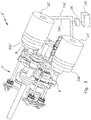
- the Fig. 2 shows the drive unit 2 in a perspective view.
- a transmission housing 14 a transmission 3 with a first shift stage shaft 10 and a second shift stage shaft 11 is arranged.
- the first drive 5 is arranged, which is directly connected to the PTO shaft 9, in this embodiment in one piece.
- Below the switching stage shafts 10, 11 of the first output 7 is arranged and positively connected thereto.
- the switching stage shafts 10, 11 have the same number of switching stages, in the embodiment shown in each case two.
- the first shift stage shaft 10 and the second shift stage shaft 11 and the first output 7 form a transmission gear with four independent gears or shift stages.
- shift forks 12a, 12b, 12c are also visible.
- the shift fork 12a it is possible to switch between two shift positions S2, S4 of the first shift step shaft 10 or to select them.
- With the shift fork 12b can be selected or switched between two shift stages S1, S3 of the second shift stage shaft 11.
- a second drive 6 to the second Switching shaft 11 is switched or coupled or decoupled with this.
- the shift fork 12c simultaneously forms a drive source cut-off 23b.
- a second output 8 is still the Fig. 2 removable, can be diverted to the power from the first drive 5.
- the generator unit 20 is designed as a hydraulic pump, which is controllable, in particular as a swash plate pump is formed.
- the second drive source 21 is in this embodiment as a hydraulic motor, for. B. as inclined axis motor executed. Via hydraulic lines 15a, 15b, the generator unit 20, d. H. the hydraulic pump, with the second drive source 21, d. H. the hydraulic motor, hydraulically connected.
- the generator unit 20 can be driven by the second output 8, absorb power and provide the second drive source 21 hydraulically available.
- the second drive source 21 in turn can drive the second drive 6 hydrostatically.
- the generator unit 20 and the second drive source 21 thus form a continuously variable, hydraulic transmission.
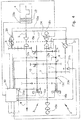
- a drive unit 2 ' essentially extends from the drive unit 2 of FIG Fig. 2 differs in that a generator unit 20 'is designed in this embodiment as an electric generator.
- a second drive source 21 ' is designed in this embodiment as an electric motor.
- the generator unit 20 ' is driven by the second output 8. It can be seen, however, that the second output 8 is not guided directly on the generator unit 20 '. Rather, a modulation unit 22a 'is interposed between the second output 8 and the generator unit 20'. This serves to adapt the rotational speeds of the second output 8 to the requirements of the generator unit 20 '.
- the modulation unit 22a ' is designed as a transmission gear, which is designed in this case to increase the efficiency of the electric generator or the generator unit 20' speed increasing.
- the modulation unit 22a ' is designed as a planetary gear.
- the generator unit 20 'and the second drive source 21' are connected to each other via electrical lines 15a ', 15b'.
- the generator unit 20 ' can feed the second drive source 21', ie the electric motor.
- the same transmission 3 can also be used for different types of generator units 20, 20 'or second drive sources 21, 21'.
- an accumulator 25 'with a charge / discharge control 26' is connected to the generator unit 20 'and to the second drive source 21' via the electric lines 15a ', 15b'.
- the charge / discharge control 26 ' functions essentially as a DC or inverter.
- the accumulator 25 ' can be loaded as needed by the generator unit 20' and, as needed, the second drive source 21 'parallel or alternatively to the generator unit 20' supply.
- the Fig. 4 now shows the drive unit 2 and the transmission 3 of the Fig. 2 in a schematic representation. It can be seen that the first drive source 4 drives the first drive 5 via a modulation unit 22 and a drive source shut-off 23a in the form of a clutch.
- the modulation unit 22 is designed as a transmission gear, so that the first drive source 4, d. H. the internal combustion engine, can be operated in an adapted for this energy-saving speed range.
- the first drive 5 is directly connected to the PTO 9. From the first drive 5, the second output 8 branches off. The second output 8 is connected to the generator unit 20.
- the first drive 5 with the first switching stage shaft 10 can be coupled.
- the first drive 5 can be coupled to the second shift stage shaft 11 by means of a clutch 16b.
- the shift fork 12a and the shift fork 12b can be changed between the two shift stages S2, S4 of the first shift stage shaft 10 and the shift stages S1, S3 of the second shift stage shaft 11 or these are selected.
- the first drive 5 via four different transmission ratios or Shifting stages S1, S2, S3, S4 of the first output 7, are connected to the wheel axles 18a, 18b of the mobile work machine 1, driven.
- the work machine 1 ( Fig. 1 ) with the aid of the first drive source 4, ie the internal combustion engine, without the interposition of the second drive source 21, ie the hydraulic motor to drive.
- a four-wheel drive 24 designed as a clutch is arranged, with which it is possible to switch over between one-axle and two-axle drive.
- the second drive source 21 is connected to the second drive 6 and this in turn can be switched to the second shift stage shaft 11 with the aid of the shift fork 12c or the drive source shutdown 23b.
- the first output 7 can thus be driven, for example, in a working mode in which the mobile work machine 1 is to be hydrostatically driven by controlling the second drive source 21 as well as by selecting one of the two switching stages S1, S3 to realize different torques or speeds.
- the first drive 5 are thus both shift stage shafts 10, 11 and all shift stages S1, S2, S3, S4 assigned, while the second drive 6, only the second shift stage shaft 11 and thus two switching stages S1, S3 are assigned.
- a control unit 30 is provided with all controllable elements of the drive unit 2, in particular with the shift forks 12a, 12b, 12c or the drive source shutdown 23b, the two clutches 16a, 16b, the drive source shutdown 23a, the all-wheel drive 24 and with control inputs of the generator unit 20 and the second Drive source 21 connected.
- the control unit 30 is set up to control the elements connected to the control unit 30, depending on the operating mode.
- the Fig. 4 removable, that the control unit 30 is each separately connected to the clutches 16a, 16b.
- the clutches 16a, 16b are independently controllable.
- control unit 30 is further connected to sensors 31a-31c, which supply the control unit 30 with control-relevant data, in particular torques and rotational speeds, for example the drives 5, 6 and the output 7.
- the control unit 30 is in particular configured to deactivate the drive source deactivation 23 a in the operating mode of operation, ie to connect the first drive source 4 to the first drive 5.
- the first drive source 4 exclusively drives the PTO shaft 9.
- the rotational speed of the first drive source 4 can thus be adapted to the requirements of a device connected to the PTO shaft 9 and adjusted, for example, to 1,000 rpm.
- the clutches 16a, 16b are initially connected in free-running mode in this operating mode.
- the second shift stage shaft 11 is connected to the second drive source 21 via the second drive 6.
- the second drive source 21 drives the wheel axles 18a, 18b via the first output 7.
- the control unit 30 can switch the transmission 3 in the manner of a dual-clutch transmission formed by the first shift stage shaft 10 and the second shift stage shaft 11 and the clutches 16a, 16b.
- the control unit 30 may first select a shift stage S2 or S4, for example shift stage S2, by means of the shift fork 12a and then couple the first drive 5 via the first shift stage shaft 10 to the first output 7 by means of the clutches 16a, 16b and, in particular, to reduce energy losses to decouple the second drive 6 from the second shift stage shaft 11 by means of the shift fork 12c or the drive source shutoff 23b.
- this switching stage change is power interruption free.
- the first shift stage shaft 10 with the first drive 5 and the first output 7 positively connected is the first shift stage shaft 10 with the first drive 5 and the first output 7 positively connected.
- the second shift stage shaft 11 is selectively and independently of the first shift stage shaft 10 with the first drive 5 or with the second drive 6 and with the first output 7 positively connected and thus in particular also decoupled. Thus, it can be changed in a simple manner between operating modes even while driving the mobile machine 1.
- control unit 30 In order to switch within one of the two switching stage shafts 10, 11, a switching stage also power interruption, controls in this Embodiment, the control unit 30 briefly first a switching stage of each other switching stage shaft 10, 11, selects the desired switching stage and then switches back to the initial switching stage shaft 10, 11 back.
- control unit 30 for fully automatic control of the transmission 3 in accordance with preset switching strategies selects switching stages and drive sources.
Landscapes
- Engineering & Computer Science (AREA)
- Mechanical Engineering (AREA)
- General Engineering & Computer Science (AREA)
- Chemical & Material Sciences (AREA)
- Combustion & Propulsion (AREA)
- Transportation (AREA)
- Arrangement Of Transmissions (AREA)
Applications Claiming Priority (1)
| Application Number | Priority Date | Filing Date | Title |
|---|---|---|---|
| DE102016107941.3A DE102016107941A1 (de) | 2016-04-28 | 2016-04-28 | Getriebe für eine fahrbare Arbeitsmaschine sowie Antriebseinheit |
Publications (2)
| Publication Number | Publication Date |
|---|---|
| EP3239559A1 true EP3239559A1 (fr) | 2017-11-01 |
| EP3239559B1 EP3239559B1 (fr) | 2020-01-29 |
Family
ID=58530397
Family Applications (1)
| Application Number | Title | Priority Date | Filing Date |
|---|---|---|---|
| EP17165240.7A Active EP3239559B1 (fr) | 2016-04-28 | 2017-04-06 | Entraînement pour une machine de travail automobile et unité d'entraînement |
Country Status (2)
| Country | Link |
|---|---|
| EP (1) | EP3239559B1 (fr) |
| DE (1) | DE102016107941A1 (fr) |
Cited By (1)
| Publication number | Priority date | Publication date | Assignee | Title |
|---|---|---|---|---|
| WO2020238956A1 (fr) * | 2019-05-27 | 2020-12-03 | 重庆大学 | Système de transmission susceptible de réaliser un entraînement à quatre roues et son mode de fonctionnement |
Citations (4)
| Publication number | Priority date | Publication date | Assignee | Title |
|---|---|---|---|---|
| US20060142104A1 (en) * | 2004-12-28 | 2006-06-29 | Michael Saller | Vehicle drive and a control method for a vehicle drive |
| DE102010030569A1 (de) * | 2010-06-28 | 2011-12-29 | Zf Friedrichshafen Ag | Hybridantrieb eines Kraftfahrzeugs und Verfahren zu dessen Steuerung |
| AT512975B1 (de) | 2012-03-27 | 2014-04-15 | Reformwerke Bauer & Co Ges M B H | Hydromechanisches Synchrongetriebe |
| DE102013215114A1 (de) * | 2013-08-01 | 2015-02-05 | Zf Friedrichshafen Ag | Hybridantrieb eines Kraftfahrzeugs |
Family Cites Families (1)
| Publication number | Priority date | Publication date | Assignee | Title |
|---|---|---|---|---|
| JP2013112073A (ja) * | 2011-11-25 | 2013-06-10 | Daimler Ag | ハイブリッド自動車の制御装置 |
-
2016
- 2016-04-28 DE DE102016107941.3A patent/DE102016107941A1/de not_active Ceased
-
2017
- 2017-04-06 EP EP17165240.7A patent/EP3239559B1/fr active Active
Patent Citations (4)
| Publication number | Priority date | Publication date | Assignee | Title |
|---|---|---|---|---|
| US20060142104A1 (en) * | 2004-12-28 | 2006-06-29 | Michael Saller | Vehicle drive and a control method for a vehicle drive |
| DE102010030569A1 (de) * | 2010-06-28 | 2011-12-29 | Zf Friedrichshafen Ag | Hybridantrieb eines Kraftfahrzeugs und Verfahren zu dessen Steuerung |
| AT512975B1 (de) | 2012-03-27 | 2014-04-15 | Reformwerke Bauer & Co Ges M B H | Hydromechanisches Synchrongetriebe |
| DE102013215114A1 (de) * | 2013-08-01 | 2015-02-05 | Zf Friedrichshafen Ag | Hybridantrieb eines Kraftfahrzeugs |
Cited By (1)
| Publication number | Priority date | Publication date | Assignee | Title |
|---|---|---|---|---|
| WO2020238956A1 (fr) * | 2019-05-27 | 2020-12-03 | 重庆大学 | Système de transmission susceptible de réaliser un entraînement à quatre roues et son mode de fonctionnement |
Also Published As
| Publication number | Publication date |
|---|---|
| DE102016107941A1 (de) | 2017-11-02 |
| EP3239559B1 (fr) | 2020-01-29 |
Similar Documents
| Publication | Publication Date | Title |
|---|---|---|
| EP3006245B1 (fr) | Procede de commande de transmission | |
| EP1926620B1 (fr) | Systeme d'entrainement pour vehicule, et vehicule utilitaire agricole | |
| EP1926621B1 (fr) | Systeme d'entrainement pour un vehicule utilitaire industriel ou agricole et procede pour faire fonctionner un systeme d'entrainement | |
| DE102012204477B4 (de) | Getriebevorrichtung mit wenigstens einem elektrischen Variator zum stufenlosen Variieren einer Übersetzung und mit Leistungsverzweigung | |
| DE19747459C2 (de) | Hydrostatisch-mechanischer Fahrantrieb | |
| DE102018213893A1 (de) | Kraftfahrzeuggetriebe, insbesondere für ein landwirtschaftliches oder kommunales Nutzfahrzeug, sowie Kraftfahrzeugantriebsstrang | |
| DE102019214355A1 (de) | Antriebssystem eines land- oder bauwirtschaftlich nutzbaren Fahrzeugs und Verfahren zu dessen Betrieb gemeinsam mit einem zumindest einen elektrischen Verbraucher aufweisenden Anbaugerät | |
| EP1704348B1 (fr) | Boite hydrostatique mecanique a derivation de puissance | |
| EP3754226B1 (fr) | Boîte de vitesses à commande sous charge | |
| DE102018213891B4 (de) | Kraftfahrzeuggetriebe, insbesondere für ein landwirtschaftliches oder kommunales Nutzfahrzeug, sowie Kraftfahrzeugantriebsstrang | |
| EP3239559B1 (fr) | Entraînement pour une machine de travail automobile et unité d'entraînement | |
| DE102019200966A1 (de) | Leistungsverzweigtes Kraftfahrzeuggetriebe | |
| DE102018213890A1 (de) | Kraftfahrzeuggetriebe, insbesondere für ein landwirtschaftliches oder kommunales Nutzfahrzeug, sowie Kraftfahrzeugantriebsstrang | |
| DE102018213888A1 (de) | Kraftfahrzeuggetriebe, insbesondere für ein landwirtschaftliches oder kommunales Nutzfahrzeug, sowie Kraftfahrzeugantriebsstrang | |
| DE102018213876A1 (de) | Kraftfahrzeuggetriebe, insbesondere für ein landwirtschaftliches oder kommunales Nutzfahrzeug, sowie Kraftfahrzeugantriebsstrang | |
| DE102018213884B4 (de) | Kraftfahrzeuggetriebe, insbesondere für ein landwirtschaftliches oder kommunales Nutzfahrzeug, sowie Kraftfahrzeugantriebsstrang | |
| DE102016218159A1 (de) | Antriebsanordnung mit einer leistungsverzweigten Getriebevorrichtung | |
| DE102017222596B4 (de) | Stufenlos leistungsverzweigtes Getriebe | |
| DE102008040444A1 (de) | Leistungsverzweigungsgetriebe | |
| DE102018213883A1 (de) | Kraftfahrzeuggetriebe, insbesondere für ein landwirtschaftliches oder kommunales Nutzfahrzeug, sowie Kraftfahrzeugantriebsstrang | |
| DE102018213881A1 (de) | Kraftfahrzeuggetriebe, insbesondere für ein landwirtschaftliches oder kommunales Nutzfahrzeug, sowie Kraftfahrzeugantriebsstrang | |
| DE102018213879A1 (de) | Kraftfahrzeuggetriebe, insbesondere für ein landwirtschaftliches oder kommunales Nutzfahrzeug, sowie Kraftfahrzeugantriebsstrang | |
| DE102018213875A1 (de) | Kraftfahrzeuggetriebe, insbesondere für ein landwirtschaftliches oder kommunales Nutzfahrzeug, sowie Kraftfahrzeugantriebsstrang | |
| DE102022204061B4 (de) | Antriebsvorrichtung für eine Arbeitsmaschine | |
| DE102018213885B4 (de) | Kraftfahrzeuggetriebe, insbesondere für ein landwirtschaftliches oder kommunales Nutzfahrzeug, sowie Kraftfahrzeugantriebsstrang |
Legal Events
| Date | Code | Title | Description |
|---|---|---|---|
| PUAI | Public reference made under article 153(3) epc to a published international application that has entered the european phase |
Free format text: ORIGINAL CODE: 0009012 |
|
| STAA | Information on the status of an ep patent application or granted ep patent |
Free format text: STATUS: THE APPLICATION HAS BEEN PUBLISHED |
|
| AK | Designated contracting states |
Kind code of ref document: A1 Designated state(s): AL AT BE BG CH CY CZ DE DK EE ES FI FR GB GR HR HU IE IS IT LI LT LU LV MC MK MT NL NO PL PT RO RS SE SI SK SM TR |
|
| AX | Request for extension of the european patent |
Extension state: BA ME |
|
| STAA | Information on the status of an ep patent application or granted ep patent |
Free format text: STATUS: REQUEST FOR EXAMINATION WAS MADE |
|
| 17P | Request for examination filed |
Effective date: 20180410 |
|
| RBV | Designated contracting states (corrected) |
Designated state(s): AL AT BE BG CH CY CZ DE DK EE ES FI FR GB GR HR HU IE IS IT LI LT LU LV MC MK MT NL NO PL PT RO RS SE SI SK SM TR |
|
| RIC1 | Information provided on ipc code assigned before grant |
Ipc: B60K 6/387 20071001ALI20170830BHEP Ipc: F16H 3/093 20060101AFI20170830BHEP Ipc: B60K 6/547 20071001ALI20170830BHEP Ipc: F16H 47/02 20060101ALI20170830BHEP |
|
| REG | Reference to a national code |
Ref country code: DE Ref legal event code: R079 Ref document number: 502017003580 Country of ref document: DE Free format text: PREVIOUS MAIN CLASS: F16H0003093000 Ipc: B60K0006387000 |
|
| GRAP | Despatch of communication of intention to grant a patent |
Free format text: ORIGINAL CODE: EPIDOSNIGR1 |
|
| STAA | Information on the status of an ep patent application or granted ep patent |
Free format text: STATUS: GRANT OF PATENT IS INTENDED |
|
| RIC1 | Information provided on ipc code assigned before grant |
Ipc: B60K 6/387 20071001AFI20190912BHEP Ipc: B60K 6/547 20071001ALI20190912BHEP Ipc: F16H 47/02 20060101ALI20190912BHEP |
|
| INTG | Intention to grant announced |
Effective date: 20191015 |
|
| GRAS | Grant fee paid |
Free format text: ORIGINAL CODE: EPIDOSNIGR3 |
|
| GRAA | (expected) grant |
Free format text: ORIGINAL CODE: 0009210 |
|
| STAA | Information on the status of an ep patent application or granted ep patent |
Free format text: STATUS: THE PATENT HAS BEEN GRANTED |
|
| AK | Designated contracting states |
Kind code of ref document: B1 Designated state(s): AL AT BE BG CH CY CZ DE DK EE ES FI FR GB GR HR HU IE IS IT LI LT LU LV MC MK MT NL NO PL PT RO RS SE SI SK SM TR |
|
| REG | Reference to a national code |
Ref country code: GB Ref legal event code: FG4D Free format text: NOT ENGLISH |
|
| REG | Reference to a national code |
Ref country code: CH Ref legal event code: EP Ref country code: CH Ref legal event code: NV Representative=s name: ROTTMANN, ZIMMERMANN + PARTNER AG, CH |
|
| REG | Reference to a national code |
Ref country code: AT Ref legal event code: REF Ref document number: 1228257 Country of ref document: AT Kind code of ref document: T Effective date: 20200215 |
|
| REG | Reference to a national code |
Ref country code: IE Ref legal event code: FG4D Free format text: LANGUAGE OF EP DOCUMENT: GERMAN |
|
| REG | Reference to a national code |
Ref country code: DE Ref legal event code: R096 Ref document number: 502017003580 Country of ref document: DE |
|
| REG | Reference to a national code |
Ref country code: NL Ref legal event code: MP Effective date: 20200129 |
|
| PG25 | Lapsed in a contracting state [announced via postgrant information from national office to epo] |
Ref country code: FI Free format text: LAPSE BECAUSE OF FAILURE TO SUBMIT A TRANSLATION OF THE DESCRIPTION OR TO PAY THE FEE WITHIN THE PRESCRIBED TIME-LIMIT Effective date: 20200129 Ref country code: NO Free format text: LAPSE BECAUSE OF FAILURE TO SUBMIT A TRANSLATION OF THE DESCRIPTION OR TO PAY THE FEE WITHIN THE PRESCRIBED TIME-LIMIT Effective date: 20200429 Ref country code: RS Free format text: LAPSE BECAUSE OF FAILURE TO SUBMIT A TRANSLATION OF THE DESCRIPTION OR TO PAY THE FEE WITHIN THE PRESCRIBED TIME-LIMIT Effective date: 20200129 Ref country code: PT Free format text: LAPSE BECAUSE OF FAILURE TO SUBMIT A TRANSLATION OF THE DESCRIPTION OR TO PAY THE FEE WITHIN THE PRESCRIBED TIME-LIMIT Effective date: 20200621 |
|
| REG | Reference to a national code |
Ref country code: LT Ref legal event code: MG4D |
|
| PG25 | Lapsed in a contracting state [announced via postgrant information from national office to epo] |
Ref country code: IS Free format text: LAPSE BECAUSE OF FAILURE TO SUBMIT A TRANSLATION OF THE DESCRIPTION OR TO PAY THE FEE WITHIN THE PRESCRIBED TIME-LIMIT Effective date: 20200529 Ref country code: GR Free format text: LAPSE BECAUSE OF FAILURE TO SUBMIT A TRANSLATION OF THE DESCRIPTION OR TO PAY THE FEE WITHIN THE PRESCRIBED TIME-LIMIT Effective date: 20200430 Ref country code: BG Free format text: LAPSE BECAUSE OF FAILURE TO SUBMIT A TRANSLATION OF THE DESCRIPTION OR TO PAY THE FEE WITHIN THE PRESCRIBED TIME-LIMIT Effective date: 20200429 Ref country code: LV Free format text: LAPSE BECAUSE OF FAILURE TO SUBMIT A TRANSLATION OF THE DESCRIPTION OR TO PAY THE FEE WITHIN THE PRESCRIBED TIME-LIMIT Effective date: 20200129 Ref country code: SE Free format text: LAPSE BECAUSE OF FAILURE TO SUBMIT A TRANSLATION OF THE DESCRIPTION OR TO PAY THE FEE WITHIN THE PRESCRIBED TIME-LIMIT Effective date: 20200129 Ref country code: HR Free format text: LAPSE BECAUSE OF FAILURE TO SUBMIT A TRANSLATION OF THE DESCRIPTION OR TO PAY THE FEE WITHIN THE PRESCRIBED TIME-LIMIT Effective date: 20200129 |
|
| PG25 | Lapsed in a contracting state [announced via postgrant information from national office to epo] |
Ref country code: NL Free format text: LAPSE BECAUSE OF FAILURE TO SUBMIT A TRANSLATION OF THE DESCRIPTION OR TO PAY THE FEE WITHIN THE PRESCRIBED TIME-LIMIT Effective date: 20200129 |
|
| PG25 | Lapsed in a contracting state [announced via postgrant information from national office to epo] |
Ref country code: ES Free format text: LAPSE BECAUSE OF FAILURE TO SUBMIT A TRANSLATION OF THE DESCRIPTION OR TO PAY THE FEE WITHIN THE PRESCRIBED TIME-LIMIT Effective date: 20200129 Ref country code: DK Free format text: LAPSE BECAUSE OF FAILURE TO SUBMIT A TRANSLATION OF THE DESCRIPTION OR TO PAY THE FEE WITHIN THE PRESCRIBED TIME-LIMIT Effective date: 20200129 Ref country code: SK Free format text: LAPSE BECAUSE OF FAILURE TO SUBMIT A TRANSLATION OF THE DESCRIPTION OR TO PAY THE FEE WITHIN THE PRESCRIBED TIME-LIMIT Effective date: 20200129 Ref country code: EE Free format text: LAPSE BECAUSE OF FAILURE TO SUBMIT A TRANSLATION OF THE DESCRIPTION OR TO PAY THE FEE WITHIN THE PRESCRIBED TIME-LIMIT Effective date: 20200129 Ref country code: SM Free format text: LAPSE BECAUSE OF FAILURE TO SUBMIT A TRANSLATION OF THE DESCRIPTION OR TO PAY THE FEE WITHIN THE PRESCRIBED TIME-LIMIT Effective date: 20200129 Ref country code: CZ Free format text: LAPSE BECAUSE OF FAILURE TO SUBMIT A TRANSLATION OF THE DESCRIPTION OR TO PAY THE FEE WITHIN THE PRESCRIBED TIME-LIMIT Effective date: 20200129 Ref country code: LT Free format text: LAPSE BECAUSE OF FAILURE TO SUBMIT A TRANSLATION OF THE DESCRIPTION OR TO PAY THE FEE WITHIN THE PRESCRIBED TIME-LIMIT Effective date: 20200129 Ref country code: RO Free format text: LAPSE BECAUSE OF FAILURE TO SUBMIT A TRANSLATION OF THE DESCRIPTION OR TO PAY THE FEE WITHIN THE PRESCRIBED TIME-LIMIT Effective date: 20200129 |
|
| REG | Reference to a national code |
Ref country code: DE Ref legal event code: R097 Ref document number: 502017003580 Country of ref document: DE |
|
| PG25 | Lapsed in a contracting state [announced via postgrant information from national office to epo] |
Ref country code: MC Free format text: LAPSE BECAUSE OF FAILURE TO SUBMIT A TRANSLATION OF THE DESCRIPTION OR TO PAY THE FEE WITHIN THE PRESCRIBED TIME-LIMIT Effective date: 20200129 |
|
| PLBE | No opposition filed within time limit |
Free format text: ORIGINAL CODE: 0009261 |
|
| STAA | Information on the status of an ep patent application or granted ep patent |
Free format text: STATUS: NO OPPOSITION FILED WITHIN TIME LIMIT |
|
| 26N | No opposition filed |
Effective date: 20201030 |
|
| PG25 | Lapsed in a contracting state [announced via postgrant information from national office to epo] |
Ref country code: LU Free format text: LAPSE BECAUSE OF NON-PAYMENT OF DUE FEES Effective date: 20200406 |
|
| REG | Reference to a national code |
Ref country code: BE Ref legal event code: MM Effective date: 20200430 |
|
| PG25 | Lapsed in a contracting state [announced via postgrant information from national office to epo] |
Ref country code: PL Free format text: LAPSE BECAUSE OF FAILURE TO SUBMIT A TRANSLATION OF THE DESCRIPTION OR TO PAY THE FEE WITHIN THE PRESCRIBED TIME-LIMIT Effective date: 20200129 Ref country code: SI Free format text: LAPSE BECAUSE OF FAILURE TO SUBMIT A TRANSLATION OF THE DESCRIPTION OR TO PAY THE FEE WITHIN THE PRESCRIBED TIME-LIMIT Effective date: 20200129 Ref country code: BE Free format text: LAPSE BECAUSE OF NON-PAYMENT OF DUE FEES Effective date: 20200430 |
|
| GBPC | Gb: european patent ceased through non-payment of renewal fee |
Effective date: 20210406 |
|
| PG25 | Lapsed in a contracting state [announced via postgrant information from national office to epo] |
Ref country code: GB Free format text: LAPSE BECAUSE OF NON-PAYMENT OF DUE FEES Effective date: 20210406 |
|
| PG25 | Lapsed in a contracting state [announced via postgrant information from national office to epo] |
Ref country code: TR Free format text: LAPSE BECAUSE OF FAILURE TO SUBMIT A TRANSLATION OF THE DESCRIPTION OR TO PAY THE FEE WITHIN THE PRESCRIBED TIME-LIMIT Effective date: 20200129 Ref country code: MT Free format text: LAPSE BECAUSE OF FAILURE TO SUBMIT A TRANSLATION OF THE DESCRIPTION OR TO PAY THE FEE WITHIN THE PRESCRIBED TIME-LIMIT Effective date: 20200129 Ref country code: CY Free format text: LAPSE BECAUSE OF FAILURE TO SUBMIT A TRANSLATION OF THE DESCRIPTION OR TO PAY THE FEE WITHIN THE PRESCRIBED TIME-LIMIT Effective date: 20200129 |
|
| PG25 | Lapsed in a contracting state [announced via postgrant information from national office to epo] |
Ref country code: MK Free format text: LAPSE BECAUSE OF FAILURE TO SUBMIT A TRANSLATION OF THE DESCRIPTION OR TO PAY THE FEE WITHIN THE PRESCRIBED TIME-LIMIT Effective date: 20200129 Ref country code: AL Free format text: LAPSE BECAUSE OF FAILURE TO SUBMIT A TRANSLATION OF THE DESCRIPTION OR TO PAY THE FEE WITHIN THE PRESCRIBED TIME-LIMIT Effective date: 20200129 |
|
| PGFP | Annual fee paid to national office [announced via postgrant information from national office to epo] |
Ref country code: IT Payment date: 20230428 Year of fee payment: 7 Ref country code: IE Payment date: 20230425 Year of fee payment: 7 Ref country code: FR Payment date: 20230417 Year of fee payment: 7 Ref country code: DE Payment date: 20230425 Year of fee payment: 7 Ref country code: CH Payment date: 20230502 Year of fee payment: 7 |
|
| PGFP | Annual fee paid to national office [announced via postgrant information from national office to epo] |
Ref country code: AT Payment date: 20230414 Year of fee payment: 7 |