EP3239553A1 - Axle for industrial vehicle - Google Patents
Axle for industrial vehicle Download PDFInfo
- Publication number
- EP3239553A1 EP3239553A1 EP14909006.0A EP14909006A EP3239553A1 EP 3239553 A1 EP3239553 A1 EP 3239553A1 EP 14909006 A EP14909006 A EP 14909006A EP 3239553 A1 EP3239553 A1 EP 3239553A1
- Authority
- EP
- European Patent Office
- Prior art keywords
- brake
- axle
- housing
- plates
- industrial vehicle
- Prior art date
- Legal status (The legal status is an assumption and is not a legal conclusion. Google has not performed a legal analysis and makes no representation as to the accuracy of the status listed.)
- Granted
Links
- 230000005540 biological transmission Effects 0.000 claims abstract description 60
- 239000003921 oil Substances 0.000 claims description 27
- 239000010720 hydraulic oil Substances 0.000 claims description 8
- 238000007599 discharging Methods 0.000 description 5
- 230000013011 mating Effects 0.000 description 5
- 238000001816 cooling Methods 0.000 description 3
- 238000012423 maintenance Methods 0.000 description 3
- 238000010438 heat treatment Methods 0.000 description 2
- 230000000694 effects Effects 0.000 description 1
Images


Classifications
-
- B—PERFORMING OPERATIONS; TRANSPORTING
- B60—VEHICLES IN GENERAL
- B60T—VEHICLE BRAKE CONTROL SYSTEMS OR PARTS THEREOF; BRAKE CONTROL SYSTEMS OR PARTS THEREOF, IN GENERAL; ARRANGEMENT OF BRAKING ELEMENTS ON VEHICLES IN GENERAL; PORTABLE DEVICES FOR PREVENTING UNWANTED MOVEMENT OF VEHICLES; VEHICLE MODIFICATIONS TO FACILITATE COOLING OF BRAKES
- B60T1/00—Arrangements of braking elements, i.e. of those parts where braking effect occurs specially for vehicles
- B60T1/02—Arrangements of braking elements, i.e. of those parts where braking effect occurs specially for vehicles acting by retarding wheels
- B60T1/06—Arrangements of braking elements, i.e. of those parts where braking effect occurs specially for vehicles acting by retarding wheels acting otherwise than on tread, e.g. employing rim, drum, disc, or transmission or on double wheels
- B60T1/062—Arrangements of braking elements, i.e. of those parts where braking effect occurs specially for vehicles acting by retarding wheels acting otherwise than on tread, e.g. employing rim, drum, disc, or transmission or on double wheels acting on transmission parts
-
- B—PERFORMING OPERATIONS; TRANSPORTING
- B66—HOISTING; LIFTING; HAULING
- B66F—HOISTING, LIFTING, HAULING OR PUSHING, NOT OTHERWISE PROVIDED FOR, e.g. DEVICES WHICH APPLY A LIFTING OR PUSHING FORCE DIRECTLY TO THE SURFACE OF A LOAD
- B66F9/00—Devices for lifting or lowering bulky or heavy goods for loading or unloading purposes
- B66F9/06—Devices for lifting or lowering bulky or heavy goods for loading or unloading purposes movable, with their loads, on wheels or the like, e.g. fork-lift trucks
- B66F9/075—Constructional features or details
- B66F9/07572—Propulsion arrangements
-
- B—PERFORMING OPERATIONS; TRANSPORTING
- B60—VEHICLES IN GENERAL
- B60B—VEHICLE WHEELS; CASTORS; AXLES FOR WHEELS OR CASTORS; INCREASING WHEEL ADHESION
- B60B35/00—Axle units; Parts thereof ; Arrangements for lubrication of axles
- B60B35/12—Torque-transmitting axles
-
- B—PERFORMING OPERATIONS; TRANSPORTING
- B60—VEHICLES IN GENERAL
- B60B—VEHICLE WHEELS; CASTORS; AXLES FOR WHEELS OR CASTORS; INCREASING WHEEL ADHESION
- B60B35/00—Axle units; Parts thereof ; Arrangements for lubrication of axles
- B60B35/12—Torque-transmitting axles
- B60B35/16—Axle housings
-
- B—PERFORMING OPERATIONS; TRANSPORTING
- B60—VEHICLES IN GENERAL
- B60K—ARRANGEMENT OR MOUNTING OF PROPULSION UNITS OR OF TRANSMISSIONS IN VEHICLES; ARRANGEMENT OR MOUNTING OF PLURAL DIVERSE PRIME-MOVERS IN VEHICLES; AUXILIARY DRIVES FOR VEHICLES; INSTRUMENTATION OR DASHBOARDS FOR VEHICLES; ARRANGEMENTS IN CONNECTION WITH COOLING, AIR INTAKE, GAS EXHAUST OR FUEL SUPPLY OF PROPULSION UNITS IN VEHICLES
- B60K17/00—Arrangement or mounting of transmissions in vehicles
- B60K17/04—Arrangement or mounting of transmissions in vehicles characterised by arrangement, location, or kind of gearing
- B60K17/16—Arrangement or mounting of transmissions in vehicles characterised by arrangement, location, or kind of gearing of differential gearing
- B60K17/165—Arrangement or mounting of transmissions in vehicles characterised by arrangement, location, or kind of gearing of differential gearing provided between independent half axles
-
- B—PERFORMING OPERATIONS; TRANSPORTING
- B60—VEHICLES IN GENERAL
- B60K—ARRANGEMENT OR MOUNTING OF PROPULSION UNITS OR OF TRANSMISSIONS IN VEHICLES; ARRANGEMENT OR MOUNTING OF PLURAL DIVERSE PRIME-MOVERS IN VEHICLES; AUXILIARY DRIVES FOR VEHICLES; INSTRUMENTATION OR DASHBOARDS FOR VEHICLES; ARRANGEMENTS IN CONNECTION WITH COOLING, AIR INTAKE, GAS EXHAUST OR FUEL SUPPLY OF PROPULSION UNITS IN VEHICLES
- B60K17/00—Arrangement or mounting of transmissions in vehicles
- B60K17/28—Arrangement or mounting of transmissions in vehicles characterised by arrangement, location, or type of power take-off
-
- B—PERFORMING OPERATIONS; TRANSPORTING
- B60—VEHICLES IN GENERAL
- B60T—VEHICLE BRAKE CONTROL SYSTEMS OR PARTS THEREOF; BRAKE CONTROL SYSTEMS OR PARTS THEREOF, IN GENERAL; ARRANGEMENT OF BRAKING ELEMENTS ON VEHICLES IN GENERAL; PORTABLE DEVICES FOR PREVENTING UNWANTED MOVEMENT OF VEHICLES; VEHICLE MODIFICATIONS TO FACILITATE COOLING OF BRAKES
- B60T1/00—Arrangements of braking elements, i.e. of those parts where braking effect occurs specially for vehicles
- B60T1/02—Arrangements of braking elements, i.e. of those parts where braking effect occurs specially for vehicles acting by retarding wheels
- B60T1/06—Arrangements of braking elements, i.e. of those parts where braking effect occurs specially for vehicles acting by retarding wheels acting otherwise than on tread, e.g. employing rim, drum, disc, or transmission or on double wheels
-
- B—PERFORMING OPERATIONS; TRANSPORTING
- B66—HOISTING; LIFTING; HAULING
- B66F—HOISTING, LIFTING, HAULING OR PUSHING, NOT OTHERWISE PROVIDED FOR, e.g. DEVICES WHICH APPLY A LIFTING OR PUSHING FORCE DIRECTLY TO THE SURFACE OF A LOAD
- B66F9/00—Devices for lifting or lowering bulky or heavy goods for loading or unloading purposes
- B66F9/06—Devices for lifting or lowering bulky or heavy goods for loading or unloading purposes movable, with their loads, on wheels or the like, e.g. fork-lift trucks
- B66F9/075—Constructional features or details
- B66F9/07509—Braking
-
- F—MECHANICAL ENGINEERING; LIGHTING; HEATING; WEAPONS; BLASTING
- F16—ENGINEERING ELEMENTS AND UNITS; GENERAL MEASURES FOR PRODUCING AND MAINTAINING EFFECTIVE FUNCTIONING OF MACHINES OR INSTALLATIONS; THERMAL INSULATION IN GENERAL
- F16D—COUPLINGS FOR TRANSMITTING ROTATION; CLUTCHES; BRAKES
- F16D55/00—Brakes with substantially-radial braking surfaces pressed together in axial direction, e.g. disc brakes
- F16D55/24—Brakes with substantially-radial braking surfaces pressed together in axial direction, e.g. disc brakes with a plurality of axially-movable discs, lamellae, or pads, pressed from one side towards an axially-located member
- F16D55/26—Brakes with substantially-radial braking surfaces pressed together in axial direction, e.g. disc brakes with a plurality of axially-movable discs, lamellae, or pads, pressed from one side towards an axially-located member without self-tightening action
- F16D55/36—Brakes with a plurality of rotating discs all lying side by side
- F16D55/40—Brakes with a plurality of rotating discs all lying side by side actuated by a fluid-pressure device arranged in or one the brake
-
- F—MECHANICAL ENGINEERING; LIGHTING; HEATING; WEAPONS; BLASTING
- F16—ENGINEERING ELEMENTS AND UNITS; GENERAL MEASURES FOR PRODUCING AND MAINTAINING EFFECTIVE FUNCTIONING OF MACHINES OR INSTALLATIONS; THERMAL INSULATION IN GENERAL
- F16D—COUPLINGS FOR TRANSMITTING ROTATION; CLUTCHES; BRAKES
- F16D59/00—Self-acting brakes, e.g. coming into operation at a predetermined speed
- F16D59/02—Self-acting brakes, e.g. coming into operation at a predetermined speed spring-loaded and adapted to be released by mechanical, fluid, or electromagnetic means
-
- F—MECHANICAL ENGINEERING; LIGHTING; HEATING; WEAPONS; BLASTING
- F16—ENGINEERING ELEMENTS AND UNITS; GENERAL MEASURES FOR PRODUCING AND MAINTAINING EFFECTIVE FUNCTIONING OF MACHINES OR INSTALLATIONS; THERMAL INSULATION IN GENERAL
- F16D—COUPLINGS FOR TRANSMITTING ROTATION; CLUTCHES; BRAKES
- F16D65/00—Parts or details
- F16D65/14—Actuating mechanisms for brakes; Means for initiating operation at a predetermined position
- F16D65/16—Actuating mechanisms for brakes; Means for initiating operation at a predetermined position arranged in or on the brake
- F16D65/18—Actuating mechanisms for brakes; Means for initiating operation at a predetermined position arranged in or on the brake adapted for drawing members together, e.g. for disc brakes
- F16D65/186—Actuating mechanisms for brakes; Means for initiating operation at a predetermined position arranged in or on the brake adapted for drawing members together, e.g. for disc brakes with full-face force-applying member, e.g. annular
-
- B—PERFORMING OPERATIONS; TRANSPORTING
- B60—VEHICLES IN GENERAL
- B60Y—INDEXING SCHEME RELATING TO ASPECTS CROSS-CUTTING VEHICLE TECHNOLOGY
- B60Y2200/00—Type of vehicle
- B60Y2200/10—Road Vehicles
- B60Y2200/15—Fork lift trucks, Industrial trucks
-
- B—PERFORMING OPERATIONS; TRANSPORTING
- B60—VEHICLES IN GENERAL
- B60Y—INDEXING SCHEME RELATING TO ASPECTS CROSS-CUTTING VEHICLE TECHNOLOGY
- B60Y2300/00—Purposes or special features of road vehicle drive control systems
- B60Y2300/18—Propelling the vehicle
- B60Y2300/18008—Propelling the vehicle related to particular drive situations
- B60Y2300/18108—Braking
- B60Y2300/18141—Braking for parking
-
- B—PERFORMING OPERATIONS; TRANSPORTING
- B60—VEHICLES IN GENERAL
- B60Y—INDEXING SCHEME RELATING TO ASPECTS CROSS-CUTTING VEHICLE TECHNOLOGY
- B60Y2410/00—Constructional features of vehicle sub-units
- B60Y2410/10—Housings
-
- B—PERFORMING OPERATIONS; TRANSPORTING
- B60—VEHICLES IN GENERAL
- B60Y—INDEXING SCHEME RELATING TO ASPECTS CROSS-CUTTING VEHICLE TECHNOLOGY
- B60Y2410/00—Constructional features of vehicle sub-units
- B60Y2410/102—Shaft arrangements; Shaft supports, e.g. bearings
-
- F—MECHANICAL ENGINEERING; LIGHTING; HEATING; WEAPONS; BLASTING
- F16—ENGINEERING ELEMENTS AND UNITS; GENERAL MEASURES FOR PRODUCING AND MAINTAINING EFFECTIVE FUNCTIONING OF MACHINES OR INSTALLATIONS; THERMAL INSULATION IN GENERAL
- F16D—COUPLINGS FOR TRANSMITTING ROTATION; CLUTCHES; BRAKES
- F16D2121/00—Type of actuator operation force
- F16D2121/02—Fluid pressure
- F16D2121/04—Fluid pressure acting on a piston-type actuator, e.g. for liquid pressure
- F16D2121/06—Fluid pressure acting on a piston-type actuator, e.g. for liquid pressure for releasing a normally applied brake
-
- F—MECHANICAL ENGINEERING; LIGHTING; HEATING; WEAPONS; BLASTING
- F16—ENGINEERING ELEMENTS AND UNITS; GENERAL MEASURES FOR PRODUCING AND MAINTAINING EFFECTIVE FUNCTIONING OF MACHINES OR INSTALLATIONS; THERMAL INSULATION IN GENERAL
- F16D—COUPLINGS FOR TRANSMITTING ROTATION; CLUTCHES; BRAKES
- F16D2121/00—Type of actuator operation force
- F16D2121/14—Mechanical
- F16D2121/16—Mechanical for releasing a normally applied brake
-
- F—MECHANICAL ENGINEERING; LIGHTING; HEATING; WEAPONS; BLASTING
- F16—ENGINEERING ELEMENTS AND UNITS; GENERAL MEASURES FOR PRODUCING AND MAINTAINING EFFECTIVE FUNCTIONING OF MACHINES OR INSTALLATIONS; THERMAL INSULATION IN GENERAL
- F16D—COUPLINGS FOR TRANSMITTING ROTATION; CLUTCHES; BRAKES
- F16D51/00—Brakes with outwardly-movable braking members co-operating with the inner surface of a drum or the like
- F16D51/16—Brakes with outwardly-movable braking members co-operating with the inner surface of a drum or the like shaped as brake-shoes pivoted on a fixed or nearly-fixed axis
- F16D51/18—Brakes with outwardly-movable braking members co-operating with the inner surface of a drum or the like shaped as brake-shoes pivoted on a fixed or nearly-fixed axis with two brake-shoes
- F16D51/20—Brakes with outwardly-movable braking members co-operating with the inner surface of a drum or the like shaped as brake-shoes pivoted on a fixed or nearly-fixed axis with two brake-shoes extending in opposite directions from their pivots
Landscapes
- Engineering & Computer Science (AREA)
- Mechanical Engineering (AREA)
- Transportation (AREA)
- General Engineering & Computer Science (AREA)
- Structural Engineering (AREA)
- Chemical & Material Sciences (AREA)
- Combustion & Propulsion (AREA)
- Civil Engineering (AREA)
- Geology (AREA)
- Life Sciences & Earth Sciences (AREA)
- Physics & Mathematics (AREA)
- Electromagnetism (AREA)
- Braking Arrangements (AREA)
- Arrangement And Driving Of Transmission Devices (AREA)
Abstract
Description
- The present invention relates to an axle of an industrial vehicle provided with a parking brake.
- In some industrial vehicles such as a forklift, wet multiple disc brakes are adopted as a service brake and a parking brake of an axle. By adopting a wet multiple disc brake, the service life of the brake can be extended. Axles of this type are disclosed in, for example,
Patent Literatures -
Figure 4 is a partial sectional view of an axle of an industrial vehicle disclosed inPatent Literature 1.Figure 5 is a view taken along the line A-A ofFigure 4 . The axle comprises anaxle housing 6, anaxle shaft 60 inserted in theaxle housing 6, and aframe support 61 arranged around an outer periphery of theaxle shaft 60. An inner diameter portion of theframe support 61 is fixed to aflange portion 6a of theaxle housing 6 withbolts 62, and an outer diameter portion of theframe support 61 is fixed to aframe 63 of the body withbolts 64. - A
wheel hub 65 is arranged on the outer periphery of theaxle housing 6 viabearings 66. One end of thewheel hub 65 is fixed to aflange end portion 60a of theaxle shaft 60 withbolts 67, and the other end of thewheel hub 65 is fixed to abrake hub 68 and arim 69 of a wheel withbolts 70. Abrake cover 71 and acenter cover 72 are fixed to theframe support 61 withbolts 73. -
Friction plates 74 are engaged with splines of thebrake hub 68 so as to be movable in the axial direction of theaxle shaft 60.Mating plates 75 are engaged with splines of thecenter cover 72 so as to be movable in the axial direction of theaxle shaft 60. Thefriction plates 74 and themating plates 75 are alternately arranged in the axial direction of theaxle shaft 60. - A
parking piston 76 is arranged inside theframe support 61 so as to be movable in the axial direction of theaxle shaft 60.Parking springs 77 are arranged between theparking piston 76 and theframe support 61.Service pistons 78 are housed in theframe support 61 so as to be movable in the axial direction of theaxle shaft 60. As shown inFigure 5 , theservice pistons 78 and theparking springs 77 are arranged in a circumferential direction around anaxial center 600 of theaxle shaft 60. Anoil chamber 79 is provided for theparking piston 76. Anoil chamber 80 is provided for each of theservice pistons 78. - In order to operate the parking brake, an oil feeding/discharging device (not shown) discharges the hydraulic oil from each of the
oil chambers 80 through anoil passage 81 and an outlet 82 (seeFigure 5 ), and discharges the hydraulic oil from theoil chamber 79 through anoil passage 83. Then, theparking piston 76 is pressed against both theplates parking springs 77, and thereby theplates - In order to release the parking brake, the oil feeding/discharging device supplies the hydraulic oil to the
oil chamber 79 through theoil passage 83 to move theparking piston 76 away from theplates parking springs 77. Thereby, the pressure contact between theplates - In order to operate the service brake, the parking brake is released in advance as described above. The oil feeding/discharging device supplies the hydraulic oil to each of the
oil chambers 80 through an inlet 84 (seeFigure 5 ) and theoil passage 81. Then, theservice pistons 78 are pressed against theplates plates - As described above, in this axle, the parking brake and the service brake are integrated and share the
friction plates 74 and themating plates 75. -
- [Patent Literature 1] Japanese Patent Laid-Open No.
2003-343622 - [Patent Literature 2] Japanese Patent Laid-Open No.
2003-247573 - However, such a brake structure is very complicated and must be arranged on both right and left sides of the axle, and thereby the cost is high.
- Moreover, it is not easy to maintain this brake structure. For example, an operator can maintain the
friction plates 74, themating plates 75, theparking piston 76, theparking springs 77, and theservice pistons 78 only after detaching theaxle shaft 60, the wheel, thewheel hub 65, thebrake hub 68, and the brake cover 71 in sequence. Further, as shown inFigure 5 , theparking springs 77 and theservice pistons 78 are arranged around theaxle shaft 60, which is one of the grounds for poor accessibility. - Further, in this brake structure, since the parking brake is a negative brake, it must be released when the industrial vehicle is towed in an emergency. To release the parking brake, it is necessary to operate brake release bolts (not shown) arranged around the
axial center 600. Therefore, an operator must access the respective brake release bolts in the right and left brake structures from the inside of the lower part of theaxle housing 6. Like this, it is also not easy to release the parking brake by the brake release bolts. - The present invention has been made in view of the situation described above. An object of the present invention is to provide an axle of an industrial vehicle in which a parking brake can be maintained easily.
- In order to solve the problem described above, an axle of an industrial vehicle according to the present invention is an axle comprising an axle housing, a right and left pair of axle shafts inserted in the axle housing, a differential gear device arranged in the axle housing and configured to distribute power generated by a power source to the pair of axle shafts, a power transmission device arranged outside the axle housing and configured to transmit the power to the differential gear device, and a parking brake arranged adjacent to the power transmission device outside the axle housing.
- The power transmission device includes a transfer housing, a transmission shaft supported rotatably around its axis by the transfer housing to transmit the power to the differential gear device, and a transmission gear mounted on the transmission shaft and rotated by the power.
- The parking brake includes a brake housing, a brake shaft supported rotatably around its axis by the brake housing, a brake gear mounted on the brake shaft and meshed with the transmission gear, first brake plates attached to the brake shaft, second brake plates attached to the brake housing and alternately arranged with the first brake plates, and a brake piston arranged in the brake housing so as to move toward and away from the first brake plates and the second brake plates for bringing the first brake plates and the second brake plates into pressure contact with each other.
- It is preferable that the parking brake further includes a spring arranged in the housing to press the brake piston against the first brake plates and the second brake plates, and that
when hydraulic oil is supplied to an oil chamber in the brake housing, the brake piston is moved away from the first brake plates and the second brake plates against biasing force of the spring, and thereby the pressure contact between the first brake plates and the second brake plates is released. - It is preferable that the parking brake further includes a brake release bolt extending from the inside to the outside of the brake housing and screw-engaged with the brake piston, and that
the brake piston is moved away from the first brake plates and the second brake plates against the biasing force of the spring by the rotation of the brake release bolt, and thereby the pressure contact between the first brake plates and the second brake plates is released. - It is preferable that the parking brake is arranged adjacent to the right side of the power transmission device, and is located away from the center axis of the body of the industrial vehicle in the right direction when the axle is attached to the body.
- It is preferable that the parking brake is arranged adjacent to the left side of the power transmission device, and is located away from the center axis of the body of the industrial vehicle in the left direction when the axle is attached to the body.
- It is preferable that the axle further includes service brakes arranged on both right and left sides of the axle housing, and that
each of the service brakes is a drum brake. - The industrial vehicle may be a forklift including an engine as the drive source.
- The axle may be a front axle attached to a front part of a body of the industrial vehicle.
- According to the present invention, it is easy to access the parking brake from a side of the body. Therefore, maintenance of the parking brake, for example replacement of components such as brake plates and a brake piston can be performed easily.
-
- [
Figure 1] Figure 1 is a schematic perspective view of an axle according to an embodiment of the present invention. - [
Figure 2] Figure 2 is a cross-sectional view of an axle according to an embodiment of the present invention. - [
Figure 3] Figure 3 is a partial enlarged cross-sectional view of an axle according to an embodiment of the present invention. - [
Figure 4] Figure 4 is a cross-sectional view of a conventional front axle. - [
Figure 5] Figure 5 is a view taken along a line A-A ofFigure 4 . - Hereinafter, an axle of an industrial vehicle according to an embodiment of the present invention will be described with reference to the drawings. An axle is attached to a body of an industrial vehicle such as a forklift. In the embodiment, the industrial vehicle is a forklift having an engine as a drive source, and the axle is a front axle attached to a front part of the body of the industrial vehicle.
-
Figure 1 illustrates a schematic perspective view of the axle according to the embodiment.Figure 2 illustrates a cross-sectional view of the axle ofFigure 1 . The axle comprises anaxle housing 1, and a right and left pair ofaxle shafts 10 inserted in theaxle housing 1 and extending in a right and left direction. - The axle further comprises a
differential gear device 2 configured to distribute and transmit the power generated by the engine (not shown) to the pair ofaxle shafts 10, and apower transmission device 3 configured to transmit the power from the engine to thedifferential gear device 2. - The
differential gear device 2 is arranged in the center of theaxle housing 1. Adifferential housing 20 is rotatably supported by theaxle housing 1 viabearings 21. Aninput gear 22 has a ring shape and is fixed on the outer periphery of thedifferential housing 20 withbolts 23 to rotate integrally with thedifferential housing 20. The power from the engine is transmitted to theinput gear 22 via thepower transmission device 3. A right and left pair of output gears 24 (side gears) is arranged in thedifferential housing 20. Eachaxle shaft 10, at its inner end portion, is attached to theoutput gear 24 to rotate integrally withoutput gear 24. - A
pinion shaft 25 is fixed to thedifferential housing 20 with apin 26 and extends perpendicular to theaxle shaft 10. A pair of pinion gears 27 is mounted rotatably with respect to thepinion shaft 25 on both ends of thepinion shaft 25. Each of the pinion gears 27 is meshed with the output gears 24. - Referring to
Figures 2 and3 , thepower transmission device 3 is arranged behind thedifferential gear device 2 outside theaxle housing 1. Thepower transmission device 3 includes atransfer housing 30. Asupport 11 is fixed to the circumference of the center opening of theaxle housing 1 withbolts 12, and thetransfer housing 30 is fixed to thesupport 11 with bolts. - The
power transmission device 3 further includes aninput shaft 32 supported rotatably about its axis by thetransfer housing 30 viabearings 31 and extending perpendicular to the right and left direction, and aninput gear 33 mounted on theinput shaft 32 to rotate integrally with theinput shaft 32. Theinput shaft 32 is connected to an output shaft of a transmission (not shown) via a universal joint 13 (seeFigure 3 ). The power from the engine is transmitted to theinput shaft 32 via the transmission. - The
power transmission device 3 further includes atransmission shaft 35 supported rotatably around its axis by thetransfer housing 30 viabearings 34 and extending perpendicular to the right and left direction, in order to transmit the power from theinput shaft 32 to thedifferential gear device 2. Thepower transmission device 3 further includes atransmission gear 36 mounted on thetransmission shaft 35 to rotate integrally with thetransmission shaft 35. Anoutput gear 37 is formed at an end of thetransmission shaft 35 and is meshed with theinput gear 22 of thedifferential gear device 2. Thetransmission gear 36 is meshed with theinput gear 33, and is rotated by the power transmitted via theinput shaft 32 and theinput gear 33. - When the power is transmitted from the engine to the
input shaft 32 via the transmission, theinput shaft 32 and theinput gear 33 are rotated integrally, and thereby thetransmission shaft 35 and thetransmission gear 36 are rotated integrally. As a result, theinput gear 22 of thedifferential gear device 2, meshed with theoutput gear 37 of thetransmission shaft 35, is rotated. In this way, thepower transmission device 3 transmits the power from the engine to thedifferential gear device 2. - When the
input gear 22 of thedifferential gear device 2 is rotated, both of the output gears 24 are rotated by thedifferential housing 20, thepinion shaft 25, and the pinion gears 27. As a result, therespective axle shafts 10 are rotated. In this way, thedifferential gear device 2 distributes and transmits the power to the pair ofaxle shafts 10. - Referring to
Figures 1 and2 , the axle further comprises twoservice brakes 4 configured to brake rotation of the wheels on both right and left sides of the axle when the industrial vehicle is traveling, and aparking brake 5 configured to block rotation of the wheels when the industrial vehicle is parked. - Referring to
Figure 2 , in the embodiment, each of theservice brake 4 is a dry drum brake. Theservice brakes 4 are arranged on both right and left sides of theaxle housing 1. Each of theservice brakes 4 includes awheel hub 42 arranged on the outer periphery of theaxle housing 1 viabearings 40 and fixed to a flange-shapedouter end portion 10a of theaxle shaft 10 withbolts 41. Each of theservice brakes 4 further includes abrake drum 44 arranged around the outer periphery of theaxle housing 1 and fixed to thewheel hub 42 withbolts 43. Arim 15 of the wheel is fixed to thewheel hub 42 and thebrake drum 44 with thebolt 43. - Each of the
service brakes 4 further includes aback plate 45 that covers the inner opening of thebrake drum 44. Both theback plate 45 and theframe support 16 are fixed to theaxle housing 1 withbolts 46. Theframe support 16 is attached to a frame 17 of the body of the industrial vehicle withbolts 18. Thereby, the axle is attached to the body. - Each of the
service brakes 4 further includes a pair ofbrake shoes 47 arranged inside thebrake drum 44, and a wheel cylinder (not shown) supported by theback plate 45. - When the pair of
brake shoes 47 is pressed against the inner wall of thebrake drum 44 by the wheel cylinder, rotation of the wheel is braked. In this way, theservice brake 4 brakes rotation of the wheel when the industrial vehicle is travelling. - Referring to
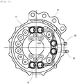
Figure 3 , theparking brake 5 is a wet multiple disc brake and is also a negative brake. Theparking brake 5 is arranged adjacent to the right side of thepower transmission device 3 outside theaxle housing 1, and is located on the lower right side of the body. This means that theparking brake 5 is located away from thecenter axis 9 of the body in the right direction when the axle is attached to the body. Areference numeral 90 inFigures 2 and3 denotes the center axis of the axle. - The
parking brake 5 includes abrake housing 50. Thebrake housing 50 is fixed to thesupport 11 withbolts 14. Thebrake housing 50 consists of a combination of a plurality of frames (first frame 50A,second frame 50B, andthird frame 50C). Thebrake housing 50 has an opening facing in a direction away from the axle housing 1 (facing rearward in the embodiment). The opening is covered with abrake cover 51. Thebrake housing 50 and thebrake cover 51 are fixed with each other withbolts 52. - The
parking brake 5 further includes abrake shaft 54 supported rotatably around its axis by thefirst frame 50A of thebrake housing 50 via abearing 53 and extending perpendicular to the right and left direction. Thebrake shaft 54 is in parallel with theinput shaft 32 and thetransmission shaft 35 of thepower transmission device 3. Thebrake shaft 54 is located across thetransmission shaft 35 from the input shaft32. Theparking brake 5 further includes abrake gear 55 mounted on thebrake shaft 54 to rotate integrally with thebrake shaft 54. Thebrake gear 55 has an outer diameter that is the same as the outer diameter of theinput gear 33 of thepower transmission device 3. Thetransfer housing 30 and thebrake housing 50 communicate with each other, and thebrake gear 55 is meshed with thetransmission gear 36. - The
parking brake 5 further includes a plurality offirst brake plates 56A (friction plates) attached to thebrake shaft 54 to rotate integrally with thebrake shaft 54, and a plurality ofsecond brake plates 56B (mating plates) attached to thebrake housing 50 not to rotate integrally with thebrake shaft 54. Each of thefirst brake plates 56A and thesecond brake plates 56B has a ring shape. Thefirst brake plates 56A are engaged with the splines formed on the outer periphery of thebrake shaft 54 so as to be movable the axial direction of thebrake shaft 54. Thesecond brake plates 56B are engaged with the splines formed on the inner periphery of thesecond frame 50B of thebrake housing 50 so as to be movable in the axial direction of thebrake shaft 54. Thefirst brake plate 56A and thesecond brake plate 56B are arranged alternately in the axial direction of thebrake shaft 54. - The
parking brake 5 further includes abrake piston 57 for bringing thefirst brake plate 56A and thesecond brake plate 56B into pressure contact with each other. Thebrake piston 57 is arranged in thebrake housing 50 so as to move toward and away from thefirst brake plates 56A and thesecond brake plates 56B in the axial direction of thebrake shaft 54. - The
parking brake 5 further includes aspring 58 arranged in thebrake housing 50. Thespring 58 is arranged between thebrake piston 57 and thebrake cover 51 in a compressed state to presses thebrake piston 57 against thefirst brake plates 56A and thesecond brake plates 56B with its biasing force. - Further, in the
brake housing 50, anoil chamber 500 is provided for releasing theparking brake 5. Theoil chamber 500 is formed by thebrake piston 57, thethird frame 50C, and acover 51. By an oil feeding/discharging device (not shown), hydraulic oil is supplied to theoil chamber 500 through an oil passage and is discharged from theoil chamber 500. - The
parking brake 5 is provided with abrake release bolt 59 for releasing theparking brake 5 in an emergency. Thebrake release bolt 59 extends perpendicular to the right and left direction and penetrates thebrake cover 51, and slightly protrudes to the outside of thebrake housing 50 in a direction separating from the axle housing 1(rearward in the embodiment). Thebrake release bolt 59 is screw-engaged with thebrake piston 57. - Operation and release of the
parking brake 5 will be described below. - The
brake piston 57 is normally pressed against thefirst brake plates 56A and thesecond brake plates 56B by the biasing force of thespring 58, and thereby thefirst brake plates 56A and thesecond brake plates 56B are brought into pressure contact with each other (see left half of theparking brake 5 inFigure 3 ). With the pressure contact, rotation of thebrake shaft 54 and thebrake gear 55 is blocked. At the same time, since thetransmission gear 36 of thepower transmission device 3 is meshed with thebrake gear 55, rotation of thetransmission shaft 35 and thetransmission gear 36 is blocked. Thereby, rotation of theaxle shaft 10 is blocked. As a result, rotation of the wheel is blocked. Theparking brake 5 operates in this manner to block rotation of the wheel when the industrial vehicle parks. - When the hydraulic oil is supplied to the
oil chamber 500 by the oil feeding/discharging device, thebrake piston 57 is moved away from thefirst brake plates 56A and thesecond brake plates 56B against the biasing force of thespring 58, and thereby the pressure contact between thefirst brake plates 56A and thesecond brake plates 56B is released (see right half of theparking brake 5 inFigure 3 ). As a result, the wheel becomes rotatable. Theparking brake 5 is released in this manner. - As the
parking brake 5 is a negative brake, it operates even when the engine is stopped. In order to tow the industrial vehicle in an emergency, it is necessary to release theparking brake 5. In that case, an operator accesses theparking brake 5 from a side (right side in the embodiment) of the body, and rotates thebrake release bolt 59 using a tool such as a wrench. By the rotation of thebrake release bolt 59, thebrake piston 57 screw-engaged with thebrake release bolt 59 is moved relative to thebrake release bolt 59 and is also moved away from thefirst brake plates 56A and thesecond brake plates 56B against the biasing force of thespring 58. Thereby, the pressure contact between thefirst brake plates 56A and thesecond brake plates 56B is released. In this way, theparking brake 5 is also released by thebrake release bolt 59. - As described above, the
parking brake 5 is a wet multiple disc brake. Theparking brake 5 is arranged adjacent to thepower transmission device 3 outside theaxle housing 1 in such a manner that thebrake gear 55 thereof are meshed with thetransmission gear 36 of thepower transmission device 3. With this arrangement, it is easy to access theparking brake 5 from a side (left side or right side) of the body. Therefore, maintenance of theparking brake 5 such as replacement of thebrake plates brake piston 57 can be performed easily. Regarding the axle in the embodiment, it is clear that the accessibility and the maintenance performance with respect to theparking brake 5 are superior, compared with the brake structure of a conventional axle shown inFigures 4 and5 . - Moreover, according to the axle shown in
Figures 4 and5 , it is necessary to arranged parking brakes on both right and left sides. Meanwhile, according to the axle of the present embodiment, oneparking brake 5 is enough. Thereby, the cost can be reduced. - The
parking brake 5 is a negative brake. In order to tow the industrial vehicle in an emergency, it is necessary to release theparking brake 5 by thebrake release bolt 59. Since it is easy to access theparking brake 5 from a side of the body as described above, theparking brake 5 can be released easily by thebrake release bolt 59. - In the conventional axle shown in
Figures 4 and5 , it is necessary to arrange a plurality of brake release bolts around theaxle shaft 60 because of the brake structure. Meanwhile, in the axle of the present embodiment, it is enough that onebrake release bolt 59 is arranged at the center of theparking brake 5. This makes it easier to release theparking brake 5 at the time of emergency. - Further, in the embodiment, the
parking brake 5 is arranged adjacent to the right side of thepower transmission device 3, and is located away from thecenter axis 9 of the body in the right direction when the axle is attached to the body. Thereby, it is easier to access theparking brake 5 from the right side of the body. Instead, theparking brake 5 may be arranged adjacent to the left side of thepower transmission device 3 and may be located away from thecenter axis 9 of the body in the left direction when the axle is attached to the body. With this configuration, it is easier to access theparking brake 5 from the left side of the body. - Since arrangement of the
parking brake 5 can be achieved only by meshing thebrake gear 55 with thetransmission gear 36 of the existingpower transmission device 3, a complicated configuration is not required. Therefore, the number of components can be reduced, and thereby the cost can be reduced. - According to the brake structure of the conventional axle shown in
Figures 4 and5 , since thebrake plates brake plates parking brake 5, the heating value is low. Therefore, cooling oil can be shared by theparking brake 5 and thedifferential gear device 2. - The
service brake 4 may be a wet brake instead of a dry brake. Further, thetransfer housing 30 and thebrake housing 50 may be formed integrally. -
- 1
- axle housing
- 10
- axle shaft
- 2
- differential gear device
- 3
- power transmission device
- 30
- transfer housing
- 35
- transmission shaft
- 36
- transmission gear
- 37
- output gear
- 4
- service brake
- 5
- parking brake
- 50
- brake housing
- 500
- oil chamber
- 54
- brake shaft
- 55
- brake gear
- 57
- brake piston
- 58
- spring
- 59
- brake release bolt
- 9
- center axis of body
Claims (8)
- An axle of an industrial vehicle, the axle comprising:an axle housing;a right and left pair of axle shafts inserted in the axle housing;a differential gear device arranged in the axle housing and configured to distribute power generated by a drive source to the pair of axle shafts;a power transmission device arranged outside the axle housing and configured to transmit the power to the differential gear device; anda parking brake arranged adjacent to the power transmission device outside the axle housing,the power transmission device including:a transfer housing;a transmission shaft supported rotatably around its axis by the transfer housing to transmit the power to the differential gear device; anda transmission gear mounted on the transmission shaft and rotated by the power,the parking brake including:a brake housing;a brake shaft supported rotatably around its axis by the brake housing;a brake gear mounted on the brake shaft and meshed with the transmission gear;first brake plates attached to the brake shaft;second brake plates attached to the brake housing and alternately arranged with the first brake plates; anda brake piston arranged in the brake housing so as to move toward and away from the first brake plates and the second brake plates for bringing the first brake plates and the second brake plates into pressure contact with each other.
- The axle of the industrial vehicle according to claim 1, wherein
the parking brake further includes a spring arranged in the brake housing to press the brake piston against the first brake plates and the second brake plates, and
when hydraulic oil is supplied to an oil chamber in the brake housing, the brake piston is moved away from the first brake plates and the second brake plates against biasing force of the spring, and thereby the pressure contact between the first brake plates and the second brake plates is released. - The axle of the industrial vehicle according to claim 2, wherein
the parking brake further includes a brake release bolt extending from inside to outside of the brake housing and screw-engaged with the brake piston, and
the brake piston is moved away from the first brake plates and the second brake plates against the biasing force of the spring by rotation of the brake release bolt, and thereby the pressure contact between the first brake plates and the second brake plates is released. - The axle of the industrial vehicle according to any one of claims 1 to 3, wherein
the parking brake is arranged adjacent to a right side of the power transmission device, and is located away from a center axis of a body of the industrial vehicle in a right direction when the axle is attached to the body. - The axle of the industrial vehicle according to any one of claims 1 to 3, wherein
the parking brake is arranged adjacent to a left side of the power transmission device, and is located away from a center axis of a body of the industrial vehicle in a left direction when the axle is attached to the body. - The axle of the industrial vehicle according to any one of claims 1 to 5, further comprising
service brakes arranged on both right and left sides of the axle housing, wherein
each of the service brakes is a drum brake. - The axle of the industrial vehicle according to any one of claims 1 to 6, wherein
the industrial vehicle is a forklift including an engine as the drive source. - The axle of the industrial vehicle according to any one of claims 1 to 7, wherein
the axle is a front axle attached to a front part of a body of the industrial vehicle.
Applications Claiming Priority (1)
| Application Number | Priority Date | Filing Date | Title |
|---|---|---|---|
| PCT/JP2014/084339 WO2016103399A1 (en) | 2014-12-25 | 2014-12-25 | Axle for industrial vehicle |
Publications (3)
| Publication Number | Publication Date |
|---|---|
| EP3239553A1 true EP3239553A1 (en) | 2017-11-01 |
| EP3239553A4 EP3239553A4 (en) | 2019-01-23 |
| EP3239553B1 EP3239553B1 (en) | 2019-09-04 |
Family
ID=56149494
Family Applications (1)
| Application Number | Title | Priority Date | Filing Date |
|---|---|---|---|
| EP14909006.0A Active EP3239553B1 (en) | 2014-12-25 | 2014-12-25 | Axle for industrial vehicle |
Country Status (5)
| Country | Link |
|---|---|
| US (1) | US10106131B2 (en) |
| EP (1) | EP3239553B1 (en) |
| JP (1) | JP5946110B1 (en) |
| CN (1) | CN107002785B (en) |
| WO (1) | WO2016103399A1 (en) |
Families Citing this family (4)
| Publication number | Priority date | Publication date | Assignee | Title |
|---|---|---|---|---|
| KR102017201B1 (en) * | 2019-03-25 | 2019-09-02 | 금아파워텍주식회사 | Common breaking device for vehicle |
| CN110043585B (en) * | 2019-04-28 | 2024-02-20 | 浙江金道科技股份有限公司 | Wet braking drive axle |
| CN110043586B (en) * | 2019-04-28 | 2024-02-20 | 浙江金道科技股份有限公司 | Driving axle and input assembly thereof |
| CN110332260B (en) * | 2019-08-12 | 2021-09-24 | 湖北康晨安宝矿业设备有限责任公司 | Front axle traveling and parking integrated brake |
Family Cites Families (14)
| Publication number | Priority date | Publication date | Assignee | Title |
|---|---|---|---|---|
| JPH07208512A (en) * | 1994-01-14 | 1995-08-11 | Kubota Corp | Negative brake |
| KR100435278B1 (en) * | 2001-09-11 | 2004-06-11 | 한승우 | Wheel transmission |
| JP2003247573A (en) | 2002-02-26 | 2003-09-05 | Mitsubishi Heavy Ind Ltd | Brake device for vehicle |
| JP4115163B2 (en) | 2002-05-29 | 2008-07-09 | 三菱重工業株式会社 | Wet multi-plate brake device for vehicles |
| KR100442475B1 (en) * | 2004-01-15 | 2004-07-30 | 한승우 | Compact Transmission installed between bevel and differential gear |
| JP2005263140A (en) * | 2004-03-22 | 2005-09-29 | Mitsubishi Heavy Ind Ltd | Driving device for vehicle |
| CN2760336Y (en) * | 2004-10-28 | 2006-02-22 | 邓浩明 | Dual-function driving vehicle bridge |
| JP2006298273A (en) * | 2005-04-22 | 2006-11-02 | Exedy Corp | Drive unit for vehicle |
| EP2000600A1 (en) * | 2006-03-29 | 2008-12-10 | Kubota Corporation | Wheel loader |
| JP4758852B2 (en) * | 2006-08-29 | 2011-08-31 | 本田技研工業株式会社 | Brake structure of wheel rotation device |
| KR100771961B1 (en) * | 2006-09-11 | 2007-11-01 | 우영유압주식회사 | Apparatus of axle including compact transmission preventing vehicle from moving backwards on upward slope |
| JP5063760B2 (en) * | 2010-08-31 | 2012-10-31 | 株式会社小松製作所 | forklift |
| KR101089207B1 (en) * | 2011-03-04 | 2011-12-05 | 주식회사 현대티엔에이 | Parking brake device of construction vehicle and forklift |
| CN203793042U (en) * | 2013-12-27 | 2014-08-27 | 陕西汉德车桥有限公司 | Steering drive axle for highly-motorized off-road vehicle |
-
2014
- 2014-12-25 US US15/533,061 patent/US10106131B2/en active Active
- 2014-12-25 CN CN201480083277.3A patent/CN107002785B/en active Active
- 2014-12-25 EP EP14909006.0A patent/EP3239553B1/en active Active
- 2014-12-25 WO PCT/JP2014/084339 patent/WO2016103399A1/en active Application Filing
- 2014-12-25 JP JP2016501700A patent/JP5946110B1/en active Active
Also Published As
| Publication number | Publication date |
|---|---|
| WO2016103399A1 (en) | 2016-06-30 |
| US20170334411A1 (en) | 2017-11-23 |
| JPWO2016103399A1 (en) | 2017-04-27 |
| EP3239553A4 (en) | 2019-01-23 |
| EP3239553B1 (en) | 2019-09-04 |
| JP5946110B1 (en) | 2016-07-05 |
| CN107002785A (en) | 2017-08-01 |
| CN107002785B (en) | 2019-04-30 |
| US10106131B2 (en) | 2018-10-23 |
Similar Documents
| Publication | Publication Date | Title |
|---|---|---|
| EP3239553B1 (en) | Axle for industrial vehicle | |
| US7493992B2 (en) | Gearbox brake for mining machinery | |
| US9550414B2 (en) | Traveling drive device for dump truck | |
| US7980365B2 (en) | Brake for a utility vehicle | |
| US20130056289A1 (en) | Travel drive device for dump truck | |
| WO2016002287A1 (en) | Power transmitting device | |
| US9903454B2 (en) | Traveling axle device | |
| US8955623B2 (en) | Hub assembly, in particular for dual wheels | |
| US20090095578A1 (en) | Brake assembly for final drive | |
| CN104019158A (en) | Normally closed type brake for hydraulic wet-type drive axle | |
| JP4115163B2 (en) | Wet multi-plate brake device for vehicles | |
| CN111152607A (en) | Motor transverse hydraulic flat-bed transport vehicle axle | |
| KR100894674B1 (en) | Automatic wet corrosion parking braking system for construction machinery axle | |
| CN101348109B (en) | Braking device of drive axle | |
| JP5077784B2 (en) | Differential gear unit for automobiles that can control driving force distribution | |
| GB1559276A (en) | Motor in-wheel units | |
| JP5930538B2 (en) | Axle with built-in wet brake | |
| JP2003247573A (en) | Brake device for vehicle | |
| CN211843960U (en) | Motor transverse hydraulic flat transport vehicle axle | |
| CN111788412B (en) | Axle device for vehicle | |
| JP6643946B2 (en) | Hydraulic clutch device and tractor | |
| JP2003343612A (en) | Brake device for vehicle and its recombination method | |
| KR102218661B1 (en) | Drive axle for motor-driven vehicles | |
| PL238013B1 (en) | Drive wheel of working machines and drive system for its use | |
| WO1998046444A1 (en) | A wheel-end assembly |
Legal Events
| Date | Code | Title | Description |
|---|---|---|---|
| STAA | Information on the status of an ep patent application or granted ep patent |
Free format text: STATUS: THE INTERNATIONAL PUBLICATION HAS BEEN MADE |
|
| PUAI | Public reference made under article 153(3) epc to a published international application that has entered the european phase |
Free format text: ORIGINAL CODE: 0009012 |
|
| STAA | Information on the status of an ep patent application or granted ep patent |
Free format text: STATUS: REQUEST FOR EXAMINATION WAS MADE |
|
| 17P | Request for examination filed |
Effective date: 20170719 |
|
| AK | Designated contracting states |
Kind code of ref document: A1 Designated state(s): AL AT BE BG CH CY CZ DE DK EE ES FI FR GB GR HR HU IE IS IT LI LT LU LV MC MK MT NL NO PL PT RO RS SE SI SK SM TR |
|
| AX | Request for extension of the european patent |
Extension state: BA ME |
|
| DAX | Request for extension of the european patent (deleted) | ||
| RAP1 | Party data changed (applicant data changed or rights of an application transferred) |
Owner name: MITSUBISHI LOGISNEXT CO., LTD. |
|
| A4 | Supplementary search report drawn up and despatched |
Effective date: 20181012 |
|
| RIC1 | Information provided on ipc code assigned before grant |
Ipc: B66F 9/075 20060101ALI20181008BHEP Ipc: B60K 17/04 20060101ALI20181008BHEP Ipc: F16D 55/40 20060101AFI20181008BHEP Ipc: B60T 1/06 20060101ALI20181008BHEP |
|
| RIC1 | Information provided on ipc code assigned before grant |
Ipc: F16D 55/40 20060101AFI20181213BHEP Ipc: B60K 17/04 20060101ALI20181213BHEP Ipc: B60T 1/06 20060101ALI20181213BHEP Ipc: B66F 9/075 20060101ALI20181213BHEP |
|
| RA4 | Supplementary search report drawn up and despatched (corrected) |
Effective date: 20181220 |
|
| GRAP | Despatch of communication of intention to grant a patent |
Free format text: ORIGINAL CODE: EPIDOSNIGR1 |
|
| STAA | Information on the status of an ep patent application or granted ep patent |
Free format text: STATUS: GRANT OF PATENT IS INTENDED |
|
| INTG | Intention to grant announced |
Effective date: 20190326 |
|
| GRAS | Grant fee paid |
Free format text: ORIGINAL CODE: EPIDOSNIGR3 |
|
| GRAA | (expected) grant |
Free format text: ORIGINAL CODE: 0009210 |
|
| STAA | Information on the status of an ep patent application or granted ep patent |
Free format text: STATUS: THE PATENT HAS BEEN GRANTED |
|
| AK | Designated contracting states |
Kind code of ref document: B1 Designated state(s): AL AT BE BG CH CY CZ DE DK EE ES FI FR GB GR HR HU IE IS IT LI LT LU LV MC MK MT NL NO PL PT RO RS SE SI SK SM TR |
|
| REG | Reference to a national code |
Ref country code: GB Ref legal event code: FG4D |
|
| REG | Reference to a national code |
Ref country code: CH Ref legal event code: EP |
|
| REG | Reference to a national code |
Ref country code: AT Ref legal event code: REF Ref document number: 1175776 Country of ref document: AT Kind code of ref document: T Effective date: 20190915 |
|
| REG | Reference to a national code |
Ref country code: DE Ref legal event code: R096 Ref document number: 602014053262 Country of ref document: DE Ref country code: IE Ref legal event code: FG4D |
|
| REG | Reference to a national code |
Ref country code: NL Ref legal event code: MP Effective date: 20190904 |
|
| REG | Reference to a national code |
Ref country code: LT Ref legal event code: MG4D |
|
| PG25 | Lapsed in a contracting state [announced via postgrant information from national office to epo] |
Ref country code: LT Free format text: LAPSE BECAUSE OF FAILURE TO SUBMIT A TRANSLATION OF THE DESCRIPTION OR TO PAY THE FEE WITHIN THE PRESCRIBED TIME-LIMIT Effective date: 20190904 Ref country code: FI Free format text: LAPSE BECAUSE OF FAILURE TO SUBMIT A TRANSLATION OF THE DESCRIPTION OR TO PAY THE FEE WITHIN THE PRESCRIBED TIME-LIMIT Effective date: 20190904 Ref country code: BG Free format text: LAPSE BECAUSE OF FAILURE TO SUBMIT A TRANSLATION OF THE DESCRIPTION OR TO PAY THE FEE WITHIN THE PRESCRIBED TIME-LIMIT Effective date: 20191204 Ref country code: NO Free format text: LAPSE BECAUSE OF FAILURE TO SUBMIT A TRANSLATION OF THE DESCRIPTION OR TO PAY THE FEE WITHIN THE PRESCRIBED TIME-LIMIT Effective date: 20191204 Ref country code: SE Free format text: LAPSE BECAUSE OF FAILURE TO SUBMIT A TRANSLATION OF THE DESCRIPTION OR TO PAY THE FEE WITHIN THE PRESCRIBED TIME-LIMIT Effective date: 20190904 Ref country code: HR Free format text: LAPSE BECAUSE OF FAILURE TO SUBMIT A TRANSLATION OF THE DESCRIPTION OR TO PAY THE FEE WITHIN THE PRESCRIBED TIME-LIMIT Effective date: 20190904 |
|
| PG25 | Lapsed in a contracting state [announced via postgrant information from national office to epo] |
Ref country code: RS Free format text: LAPSE BECAUSE OF FAILURE TO SUBMIT A TRANSLATION OF THE DESCRIPTION OR TO PAY THE FEE WITHIN THE PRESCRIBED TIME-LIMIT Effective date: 20190904 Ref country code: GR Free format text: LAPSE BECAUSE OF FAILURE TO SUBMIT A TRANSLATION OF THE DESCRIPTION OR TO PAY THE FEE WITHIN THE PRESCRIBED TIME-LIMIT Effective date: 20191205 Ref country code: AL Free format text: LAPSE BECAUSE OF FAILURE TO SUBMIT A TRANSLATION OF THE DESCRIPTION OR TO PAY THE FEE WITHIN THE PRESCRIBED TIME-LIMIT Effective date: 20190904 Ref country code: LV Free format text: LAPSE BECAUSE OF FAILURE TO SUBMIT A TRANSLATION OF THE DESCRIPTION OR TO PAY THE FEE WITHIN THE PRESCRIBED TIME-LIMIT Effective date: 20190904 Ref country code: ES Free format text: LAPSE BECAUSE OF FAILURE TO SUBMIT A TRANSLATION OF THE DESCRIPTION OR TO PAY THE FEE WITHIN THE PRESCRIBED TIME-LIMIT Effective date: 20190904 |
|
| REG | Reference to a national code |
Ref country code: AT Ref legal event code: MK05 Ref document number: 1175776 Country of ref document: AT Kind code of ref document: T Effective date: 20190904 |
|
| PG25 | Lapsed in a contracting state [announced via postgrant information from national office to epo] |
Ref country code: PL Free format text: LAPSE BECAUSE OF FAILURE TO SUBMIT A TRANSLATION OF THE DESCRIPTION OR TO PAY THE FEE WITHIN THE PRESCRIBED TIME-LIMIT Effective date: 20190904 Ref country code: AT Free format text: LAPSE BECAUSE OF FAILURE TO SUBMIT A TRANSLATION OF THE DESCRIPTION OR TO PAY THE FEE WITHIN THE PRESCRIBED TIME-LIMIT Effective date: 20190904 Ref country code: EE Free format text: LAPSE BECAUSE OF FAILURE TO SUBMIT A TRANSLATION OF THE DESCRIPTION OR TO PAY THE FEE WITHIN THE PRESCRIBED TIME-LIMIT Effective date: 20190904 Ref country code: PT Free format text: LAPSE BECAUSE OF FAILURE TO SUBMIT A TRANSLATION OF THE DESCRIPTION OR TO PAY THE FEE WITHIN THE PRESCRIBED TIME-LIMIT Effective date: 20200106 Ref country code: RO Free format text: LAPSE BECAUSE OF FAILURE TO SUBMIT A TRANSLATION OF THE DESCRIPTION OR TO PAY THE FEE WITHIN THE PRESCRIBED TIME-LIMIT Effective date: 20190904 Ref country code: NL Free format text: LAPSE BECAUSE OF FAILURE TO SUBMIT A TRANSLATION OF THE DESCRIPTION OR TO PAY THE FEE WITHIN THE PRESCRIBED TIME-LIMIT Effective date: 20190904 |
|
| PG25 | Lapsed in a contracting state [announced via postgrant information from national office to epo] |
Ref country code: SM Free format text: LAPSE BECAUSE OF FAILURE TO SUBMIT A TRANSLATION OF THE DESCRIPTION OR TO PAY THE FEE WITHIN THE PRESCRIBED TIME-LIMIT Effective date: 20190904 Ref country code: SK Free format text: LAPSE BECAUSE OF FAILURE TO SUBMIT A TRANSLATION OF THE DESCRIPTION OR TO PAY THE FEE WITHIN THE PRESCRIBED TIME-LIMIT Effective date: 20190904 Ref country code: CZ Free format text: LAPSE BECAUSE OF FAILURE TO SUBMIT A TRANSLATION OF THE DESCRIPTION OR TO PAY THE FEE WITHIN THE PRESCRIBED TIME-LIMIT Effective date: 20190904 Ref country code: IS Free format text: LAPSE BECAUSE OF FAILURE TO SUBMIT A TRANSLATION OF THE DESCRIPTION OR TO PAY THE FEE WITHIN THE PRESCRIBED TIME-LIMIT Effective date: 20200224 |
|
| REG | Reference to a national code |
Ref country code: DE Ref legal event code: R097 Ref document number: 602014053262 Country of ref document: DE |
|
| PLBE | No opposition filed within time limit |
Free format text: ORIGINAL CODE: 0009261 |
|
| STAA | Information on the status of an ep patent application or granted ep patent |
Free format text: STATUS: NO OPPOSITION FILED WITHIN TIME LIMIT |
|
| PG2D | Information on lapse in contracting state deleted |
Ref country code: IS |
|
| PG25 | Lapsed in a contracting state [announced via postgrant information from national office to epo] |
Ref country code: DK Free format text: LAPSE BECAUSE OF FAILURE TO SUBMIT A TRANSLATION OF THE DESCRIPTION OR TO PAY THE FEE WITHIN THE PRESCRIBED TIME-LIMIT Effective date: 20190904 Ref country code: IS Free format text: LAPSE BECAUSE OF FAILURE TO SUBMIT A TRANSLATION OF THE DESCRIPTION OR TO PAY THE FEE WITHIN THE PRESCRIBED TIME-LIMIT Effective date: 20200105 |
|
| REG | Reference to a national code |
Ref country code: CH Ref legal event code: PL |
|
| 26N | No opposition filed |
Effective date: 20200605 |
|
| REG | Reference to a national code |
Ref country code: BE Ref legal event code: MM Effective date: 20191231 |
|
| PG25 | Lapsed in a contracting state [announced via postgrant information from national office to epo] |
Ref country code: SI Free format text: LAPSE BECAUSE OF FAILURE TO SUBMIT A TRANSLATION OF THE DESCRIPTION OR TO PAY THE FEE WITHIN THE PRESCRIBED TIME-LIMIT Effective date: 20190904 Ref country code: MC Free format text: LAPSE BECAUSE OF FAILURE TO SUBMIT A TRANSLATION OF THE DESCRIPTION OR TO PAY THE FEE WITHIN THE PRESCRIBED TIME-LIMIT Effective date: 20190904 |
|
| PG25 | Lapsed in a contracting state [announced via postgrant information from national office to epo] |
Ref country code: FR Free format text: LAPSE BECAUSE OF NON-PAYMENT OF DUE FEES Effective date: 20191231 Ref country code: LU Free format text: LAPSE BECAUSE OF NON-PAYMENT OF DUE FEES Effective date: 20191225 Ref country code: IE Free format text: LAPSE BECAUSE OF NON-PAYMENT OF DUE FEES Effective date: 20191225 |
|
| PG25 | Lapsed in a contracting state [announced via postgrant information from national office to epo] |
Ref country code: BE Free format text: LAPSE BECAUSE OF NON-PAYMENT OF DUE FEES Effective date: 20191231 Ref country code: CH Free format text: LAPSE BECAUSE OF NON-PAYMENT OF DUE FEES Effective date: 20191231 Ref country code: LI Free format text: LAPSE BECAUSE OF NON-PAYMENT OF DUE FEES Effective date: 20191231 |
|
| PG25 | Lapsed in a contracting state [announced via postgrant information from national office to epo] |
Ref country code: CY Free format text: LAPSE BECAUSE OF FAILURE TO SUBMIT A TRANSLATION OF THE DESCRIPTION OR TO PAY THE FEE WITHIN THE PRESCRIBED TIME-LIMIT Effective date: 20190904 |
|
| PG25 | Lapsed in a contracting state [announced via postgrant information from national office to epo] |
Ref country code: HU Free format text: LAPSE BECAUSE OF FAILURE TO SUBMIT A TRANSLATION OF THE DESCRIPTION OR TO PAY THE FEE WITHIN THE PRESCRIBED TIME-LIMIT; INVALID AB INITIO Effective date: 20141225 Ref country code: MT Free format text: LAPSE BECAUSE OF FAILURE TO SUBMIT A TRANSLATION OF THE DESCRIPTION OR TO PAY THE FEE WITHIN THE PRESCRIBED TIME-LIMIT Effective date: 20190904 |
|
| PG25 | Lapsed in a contracting state [announced via postgrant information from national office to epo] |
Ref country code: TR Free format text: LAPSE BECAUSE OF FAILURE TO SUBMIT A TRANSLATION OF THE DESCRIPTION OR TO PAY THE FEE WITHIN THE PRESCRIBED TIME-LIMIT Effective date: 20190904 |
|
| PG25 | Lapsed in a contracting state [announced via postgrant information from national office to epo] |
Ref country code: MK Free format text: LAPSE BECAUSE OF FAILURE TO SUBMIT A TRANSLATION OF THE DESCRIPTION OR TO PAY THE FEE WITHIN THE PRESCRIBED TIME-LIMIT Effective date: 20190904 |
|
| P01 | Opt-out of the competence of the unified patent court (upc) registered |
Effective date: 20230517 |
|
| PGFP | Annual fee paid to national office [announced via postgrant information from national office to epo] |
Ref country code: GB Payment date: 20231220 Year of fee payment: 10 |
|
| PGFP | Annual fee paid to national office [announced via postgrant information from national office to epo] |
Ref country code: IT Payment date: 20231228 Year of fee payment: 10 Ref country code: DE Payment date: 20231214 Year of fee payment: 10 |