EP3239552B1 - Friction brake structure - Google Patents
Friction brake structure Download PDFInfo
- Publication number
- EP3239552B1 EP3239552B1 EP15873006.9A EP15873006A EP3239552B1 EP 3239552 B1 EP3239552 B1 EP 3239552B1 EP 15873006 A EP15873006 A EP 15873006A EP 3239552 B1 EP3239552 B1 EP 3239552B1
- Authority
- EP
- European Patent Office
- Prior art keywords
- brake
- brake shoe
- plate
- support plate
- opposite
- Prior art date
- Legal status (The legal status is an assumption and is not a legal conclusion. Google has not performed a legal analysis and makes no representation as to the accuracy of the status listed.)
- Active
Links
Images

Classifications
-
- F—MECHANICAL ENGINEERING; LIGHTING; HEATING; WEAPONS; BLASTING
- F16—ENGINEERING ELEMENTS AND UNITS; GENERAL MEASURES FOR PRODUCING AND MAINTAINING EFFECTIVE FUNCTIONING OF MACHINES OR INSTALLATIONS; THERMAL INSULATION IN GENERAL
- F16D—COUPLINGS FOR TRANSMITTING ROTATION; CLUTCHES; BRAKES
- F16D65/00—Parts or details
- F16D65/14—Actuating mechanisms for brakes; Means for initiating operation at a predetermined position
- F16D65/16—Actuating mechanisms for brakes; Means for initiating operation at a predetermined position arranged in or on the brake
- F16D65/18—Actuating mechanisms for brakes; Means for initiating operation at a predetermined position arranged in or on the brake adapted for drawing members together, e.g. for disc brakes
- F16D65/186—Actuating mechanisms for brakes; Means for initiating operation at a predetermined position arranged in or on the brake adapted for drawing members together, e.g. for disc brakes with full-face force-applying member, e.g. annular
-
- F—MECHANICAL ENGINEERING; LIGHTING; HEATING; WEAPONS; BLASTING
- F16—ENGINEERING ELEMENTS AND UNITS; GENERAL MEASURES FOR PRODUCING AND MAINTAINING EFFECTIVE FUNCTIONING OF MACHINES OR INSTALLATIONS; THERMAL INSULATION IN GENERAL
- F16D—COUPLINGS FOR TRANSMITTING ROTATION; CLUTCHES; BRAKES
- F16D65/00—Parts or details
- F16D65/02—Braking members; Mounting thereof
- F16D65/04—Bands, shoes or pads; Pivots or supporting members therefor
- F16D65/092—Bands, shoes or pads; Pivots or supporting members therefor for axially-engaging brakes, e.g. disc brakes
- F16D65/095—Pivots or supporting members therefor
- F16D65/097—Resilient means interposed between pads and supporting members or other brake parts
- F16D65/0971—Resilient means interposed between pads and supporting members or other brake parts transmitting brake actuation force, e.g. elements interposed between brake piston and pad
-
- H—ELECTRICITY
- H02—GENERATION; CONVERSION OR DISTRIBUTION OF ELECTRIC POWER
- H02K—DYNAMO-ELECTRIC MACHINES
- H02K7/00—Arrangements for handling mechanical energy structurally associated with dynamo-electric machines, e.g. structural association with mechanical driving motors or auxiliary dynamo-electric machines
- H02K7/10—Structural association with clutches, brakes, gears, pulleys or mechanical starters
- H02K7/102—Structural association with clutches, brakes, gears, pulleys or mechanical starters with friction brakes
-
- F—MECHANICAL ENGINEERING; LIGHTING; HEATING; WEAPONS; BLASTING
- F16—ENGINEERING ELEMENTS AND UNITS; GENERAL MEASURES FOR PRODUCING AND MAINTAINING EFFECTIVE FUNCTIONING OF MACHINES OR INSTALLATIONS; THERMAL INSULATION IN GENERAL
- F16D—COUPLINGS FOR TRANSMITTING ROTATION; CLUTCHES; BRAKES
- F16D55/00—Brakes with substantially-radial braking surfaces pressed together in axial direction, e.g. disc brakes
- F16D55/02—Brakes with substantially-radial braking surfaces pressed together in axial direction, e.g. disc brakes with axially-movable discs or pads pressed against axially-located rotating members
-
- F—MECHANICAL ENGINEERING; LIGHTING; HEATING; WEAPONS; BLASTING
- F16—ENGINEERING ELEMENTS AND UNITS; GENERAL MEASURES FOR PRODUCING AND MAINTAINING EFFECTIVE FUNCTIONING OF MACHINES OR INSTALLATIONS; THERMAL INSULATION IN GENERAL
- F16D—COUPLINGS FOR TRANSMITTING ROTATION; CLUTCHES; BRAKES
- F16D2121/00—Type of actuator operation force
- F16D2121/14—Mechanical
Definitions
- the present invention relates to a friction brake structure for a rotary electric machine such as a motor.
- FIG. 6 shows a conventional friction brake structure for a motor.
- the motor includes a motor case 100, a stator 101, and a rotor 102, and the stator 101 and the rotor 102 are provided in the motor case 100.
- the rotor 102 is supported by a rotating shaft 103.
- the rotating shaft 103 is supported on an output-side bearing 106a and an opposite-to-output-side bearing 106b.
- a brake plate 104 is fixed to the rotating shaft 103.
- a plurality of brake shoes 105 are disposed so as to face the brake plate 104.
- the brake shoes 105 are inserted into holes 108 drilled in a bearing housing portion 107 in the axial direction.
- the opposite-to-output-side bearing 106b is mounted in the bearing housing portion 107.
- Each brake shoe 105 is biased toward the brake plate 104 by a coil spring 109 so as to be in sliding contact with the brake plate 104.
- the coil spring 109 is supported by a
- the sliding contact of the brake shoes 105 on the brake plate 104 provides braking action as well as holding torque when the motor stops.
- JPH11-089173A there is disclosure of fixing, to a ring-shaped support, a plurality of brake shoes as described above.
- EP0209943A1 discloses an electric motor that has a disk brake which is designed as an electromagnetically operated spring-loaded brake, acts as a standstill brake and has a thin, elastically flexible brake disk of spring steel.
- This brake disk is immovably fixed on the motor shaft between an axially movable, rotationally fixed armature of the electromagnet and a stationary brake part which forms the outer brake housing.
- the annular stator of the electromagnet surrounds the motor shaft, with formation of a free annular space which offers room for further attaching parts, for example a tachometer generator and/or a phase-angle sensor, or else for a ball bearing carrying the shaft.
- Borne axially displaceably in the stator is a coil which, in the braking state, is pressed by compression springs against the armature, which for its part presses an annular rim zone of the brake disk, with elastic deformation of the same, against the stationary brake part. When the coil is excited, the stronger magnetic force pulls the armature back from the brake disk.
- the thin brake disk is characterized by a small moment of inertia, owing to its low weight.
- DE1243926 discloses a brake pad for a part of a disc brake, consisting of a metallic carrier and a friction lining on one side of this carrier.
- US5967272 discloses a transmission bearing cover for limiting wear of a rotatable braking mechanism in a vehicle powertrain having a clutch for releasably coupling an engine to a transmission input shaft includes an annular non-rotatable member disposable about the input shaft and having an annular projection engageable with a non-rotatable clutch release bearing assembly.
- EP1178588 discloses that, to increase an operational precision of a stepping motor, a brake plate is fixed to a rotary shaft and limited in a rotary direction.
- the present invention has an object to reduce abnormal noise production in a friction brake structure.
- an embodiment of the present invention provides a friction brake structure including: a brake plate fixed to a rotating shaft of a rotary electric machine; a ring-shaped brake shoe disposed facing the brake plate; and a brake shoe support plate which engages with a fixing portion of the rotary electric machine so as to be movable in an axial direction, and which supports the brake shoe while being biased by biasing action so as to bring the brake shoe into sliding contact with the brake plate; characterized in that the brake shoe and brake shoe support plate are arranged to exert a braking action on the rotating shaft of the rotary electric machine while the rotary electric machine is driven; and in that the brake shoe and brake shoe support plate are arranged to exert a holding torque on the rotating shaft of the rotary electric machine while the rotary electric machine stops.
- a configuration may be employed in which a protrusion is provided in either one of a surface of the brake shoe opposite to a sliding contact surface with the brake plate, and a support surface of the brake shoe support plate, and an engaging portion for engaging with the protrusion is provided in the other one.
- the brake plate may be fixed to the rotating shaft at a location outside the opposite-to-output-side bearing for supporting the rotating shaft.
- An outside diameter of the brake plate may be smaller than an outside diameter of the opposite-to-output-side bearing, and the brake plate may be supported on an inner ring portion of the opposite-to-output-side bearing.
- An outside diameter of the brake shoe may be smaller than an outside diameter of the opposite-to-output-side bearing
- the friction brake structure may further include a conical coil spring as a mechanism for applying the biasing action to the brake shoe support plate.
- the friction brake structure may further include a contact stop portion for restricting movement of the brake shoe support plate in the axial direction toward the brake plate, the movement occurring when an axial thickness of the brake shoe reduces below a predetermined value.
- the friction brake structure includes a brake plate fixed to a rotating shaft of a rotary electric machine; a ring-shaped brake shoe disposed facing the brake plate; and a brake shoe support plate which engages with a fixing portion of the rotary electric machine so as to be movable in an axial direction, and which supports the brake shoe while being biased by biasing action so as to bring the brake shoe into sliding contact with the brake plate.
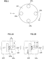
- FIG. 1 is a view illustrating the brake plate 104 and the plurality of brake shoes 105 in the motor shown in FIG. 6 as viewed from the opposite-to-output side of the motor.
- the four brake shoes 105 which are provided in the circumferential direction at even intervals, are denoted by the reference numerals 105 1 to 105 4 so as to be distinguishable from one another.
- the rotation direction of the brake plate 104 is indicated by arrow A1.
- FIGS. 2A and 2B each show the coupled system including a portion of the brake plate 104, the brake shoe 105 2 , and the coil spring 109 as viewed from the direction indicated by arrow Y of FIG. 1 .
- the elasticity, mass, and position of the brake plate 104 in FIGS. 2A and 2B are represented by k B , m B , and x B , respectively.
- the elasticity, mass, and position of the brake shoe 105 2 in FIGS. 2A and 2B are represented by k, m S , and x S , respectively.
- the elasticity of the coil spring 109 is represented by k S .
- ⁇ indicates an inclination angle of the brake shoe 105 2 observed when the portion of the brake plate 104 has moved in the direction of arrow A2 as a result of the rotation of the brake plate 104.
- the moment of inertia of the brake shoe 105 2 is represented by J S .
- the friction coefficient between the brake plate 104 and the brake shoe 105 2 is represented by ⁇ .
- the distance from the center of gravity G of the brake shoe 105 2 to the sliding contact surface 105a is represented by l 0 , and time is represented by t.
- the contact area between the brake plate 104 and the brake shoe 105 2 is represented by A, and the spring constant related to the rotation around the center of gravity G of the brake shoe 105 2 is represented by k ⁇ .
- Equation (1) is the equation of motion for the position of the brake plate.
- Equation (2) is the equation of motion for the position of the brake shoe.
- Equation (3) is the equation of motion for the rotation of the brake shoe.
- the integrand f( l ) is a function expressing the pressure between the brake plate 104 and the brake shoe 105 2 , in which l represents the coordinates on the sliding contact surface 105a in the case in which the point of intersection Q between the axis of the brake shoe 105 2 and the sliding contact surface 105a is used as a reference point.
- the matrix in the above characteristic equation is symmetric, it indicates the system is not a self-excited oscillation system, but if any pair of elements given by switching the row and column indices have opposite signs, it indicates the system is a self-excited oscillation system.
- the elements related to the rotation of the brake shoe are not symmetric, and each may possibly have an opposite sign to an element given by switching the row and column indices. This indicates a possibility that self-excited oscillation of the brake shoes may be generated in the rotation direction, which causes abnormal noises.
- JPH11-089173A discloses that the brake shoes are fixed to the ring-shaped support. In such case, as the brake plate rotates, the brake shoes might rotate slightly with respect to the ring-shaped support, which causes self-excited oscillation, and thus abnormal noises.
- a motor 1 has a motor case 10, which serves as a housing.
- a stator 11 and a rotor 12 are provided in the motor case 10.
- the rotor 12 is supported by a rotating shaft 15 supported on an output-side bearing 13 and an opposite-to-output-side bearing 14.
- the opposite-to-output-side bearing 14 is mounted in a bearing housing portion 10a which is integrally provided to the motor case 10.
- a hole 10b is drilled in the axial direction so as to communicate with the outside of the motor case 10.
- the hole 10b which is approximately oval-shaped, has two flat surface portions 10b 1 and 10b 2 formed in the outer periphery so as to face each other.
- the hole 10b has a so-called D-cut shape.
- a ring-shaped brake plate 20 is fixed to the rotating shaft 15 at a location outside the opposite-to-output-side bearing 14.
- the rotating shaft 15 passes through a hole 20a of the brake plate 20.
- the brake plate 20 is supported on an inner ring portion 14a of the opposite-to-output-side bearing 14.
- the outside diameter of the brake plate 20 is smaller than the outside diameter of the opposite-to-output-side bearing 14. The brake plate 20 rotates together with the rotating shaft 15.
- a ring-shaped brake shoe 30 is provided so as to face the brake plate 20.
- the rotating shaft 15 passes through a hole 30a of the brake shoe 30.
- the outside diameter of the brake shoe 30 is smaller than the outside diameter of the opposite-to-output-side bearing 14.
- the brake shoe 30 has four protrusions 30c in an axial end surface 30b opposite to the other axial end surface being in sliding contact with the brake plate 20.
- the protrusions 30c are provided in the circumferential direction at even intervals.
- the brake shoe 30 may be made of a material, such as a PPS (polyphenylene sulfide) resin or a PTFE (polytetrafluoroethylene) resin.
- the brake shoe 30 is supported by a ring-shaped brake shoe support plate 40 which is movable in the axial direction.
- the rotating shaft 15 passes through a first hole 40a provided at the center of the brake shoe support plate 40.
- the brake shoe support plate 40 has two flat surface portions 40b 1 and 40b 2 formed in the outer periphery 40b so as to face each other across the first hole 40a. These two flat surface portions 40b 1 and 40b 2 are provided so as to engage with the two flat surface portions 10b 1 and 10b 2 , respectively. Thus, the brake shoe support plate 40 has an approximately oval, so-called D-cut shape. The engagement of the two flat surface portions 40b 1 and 40b 2 of the brake shoe support plate 40 respectively with the flat surface portions 10b 1 and 10b 2 prevents the brake shoe support plate 40 from rotating around the rotating shaft 15 while allowing the brake shoe support plate 40 to move in the axial direction.
- the brake shoe support plate 40 has four second holes 40c provided in the circumferential direction at even intervals so as to engage respectively with the four protrusions 30c. The engagement of the four second holes 40c respectively with the four protrusions 30c fixes the brake shoe 30 onto the brake shoe support plate 40.
- a conical coil spring 50 is disposed on the outside axial end surface, which is opposite to the surface supporting the brake shoe 30, of the brake shoe support plate 40.
- the conical coil spring 50 is supported on a conical coil spring support plate 60 which is attached to the motor case 10 with screws 61.
- the brake shoe support plate 40 is biased by biasing action of the conical coil spring 50 so as to bring the brake shoe 30 into sliding contact with the brake plate 20.
- a contact stop portion 10c is provided between the opposite-to-output-side bearing 14 and an outer peripheral portion 40d of the brake shoe support plate 40.
- the outer peripheral portion 40d is located radially outside the second holes 40c.
- the contact stop portion 10c protrudes radially inward from the inner wall of the hole 10b of the bearing housing portion 10a.
- the contact stop portion 10c is provided in order to restrict the movement of the brake shoe support plate 40 in the axial direction toward the brake plate 20. Such movement is to occur when the brake shoe 30 is worn by sliding contact with the brake plate 20 enough to reduce the axial thickness of the brake shoe 30 below a predetermined value.
- the brake shoe 30 is fixed to the brake shoe support plate 40, which is prevented from rotating around the rotating shaft 15 while being allowed to move in the axial direction.
- the brake shoe 30 is prevented from rotating along with the rotation of the rotating shaft 15 and the brake plate 20, which allows for braking the rotation of the rotating shaft 15.
- the braking force of the brake shoe 30 can quickly stop the rotation of the rotating shaft 15.
- a certain holding force for the rotating shaft 15 is exerted.
- this embodiment provides braking action while the motor is driven as well as holding torque while the motor stops.
- the brake shoe 30 By bringing the brake shoe 30, which has a ring shape allowing securing of a sufficient sliding contact area, into sliding contact with the brake plate 20, the brake shoe 30 is prevented from rotating together with the brake plate 20. This reduces a rotational moment caused by a friction force of the brake shoe 30, and thus makes the spring constant of the coupled portion between the brake shoe 30 and the brake plate 20 less liable to change.
- Equation (4) to (6) expressing coupled oscillation
- the first term on the right side expresses a restoring force that causes simple harmonic motion
- the coefficient of this term is the so-called spring constant.
- the inclination angle ⁇ is included in the second or subsequent item, which brings the same effect as changes in the spring constant in the conventional technique shown in FIG. 6 .
- Equation (7) Such effect of reducing abnormal noise production will be described in relation to Equation (7). Note however that since it seems to be difficult to simply use Equation (7), which includes three variables, without any modifications, the determination on whether stable or not will be considered below by using a modified equation including two variables obtained by reducing the elements in Equation (7).
- Equation (7) which includes three variables, without any modifications, the determination on whether stable or not will be considered below by using a modified equation including two variables obtained by reducing the elements in Equation (7).
- the ring shape of the brake shoe 30 allows the brake shoe 30 to secure a sufficient sliding contact area, and thereby to prevent or reduce the brake shoe 30 from rotating together with the brake plate 20.
- Equation (9) the product of the two off-diagonal elements is positive, which indicates the system is not a self-excited oscillation system. This means that the above embodiment can reduce abnormal noise production in the brake.
- Friction against the brake plate 20 gradually wears the brake shoe 30, and reduces the axial thickness of the brake shoe 30.
- This thickness reduction moves the brake shoe support plate 40, on which a biasing force is imposed by the conical coil spring 50, toward the brake plate 20.
- the brake shoe support plate 40 eventually comes into contact with the contact stop portion 10c, which restricts the further movement of the brake shoe support plate 40 toward the brake plate 20.
- the brake shoe 30 is no longer in sliding contact with the brake plate 20. This prevents or reduces spark generation, which is expected to occur if the brake shoe 30 is in such sliding contact even after being worn to some substantial extent.
- FIG. 6 which is not provided with the contact stop portion 10c, spark generation can be prevented or reduced by limiting the free height of the coil spring 109 such that the coil spring 109 is not compressed after the brake shoes 105 have been substantially worn.
- the compression height of the coil spring 109 increases, and accordingly the biasing force of the coil spring 109 decreases. This might lead to braking force reduction.
- the presence of the contact stop portion 10c eliminates the need of limiting such spring free height. This makes it possible to select, as the conical coil spring 50, a spring having a free height large enough to exert a sufficient biasing force before the brake shoe support plate 40 comes into contact with the contact stop portion 10c. Thus, the above embodiment can provide a reliable braking force before the brake shoe support plate 40 comes into contact with the contact stop portion 10c.
- the brake plate 104 is provided axially inside the opposite-to-output-side bearing 106b.
- the brake shoes 105 are disposed radially outside the opposite-to-output-side bearing 106b so as not to interfere with the opposite-to-output-side bearing 106b.
- the brake plate 104 has a relatively large outside diameter.
- the brake shoes 105 are brought into sliding contact with the brake plate 104 at relatively distant points from the axis of the rotating shaft 103. This inevitably increases the circumferential speed of the sliding contact portions to a relatively high value.
- the wear volume of a brake shoe is proportional to the product PV of the contact pressure P [MPa] caused by the biasing force F of a spring and the circumferential speed V [m/s] at the sliding contact surface of the brake shoe.
- the wear volume increases to a large value without being dependent on P any longer. This makes it difficult to prolong brake life in FIG. 6 .
- the outside diameters of the brake plate 20 and the brake shoe 30 are both smaller than the outside diameter of the opposite-to-output-side bearing 14.
- the sliding contact portion is relatively close to the axis of the rotating shaft 15, which suppresses an increase in the circumferential speed V at the sliding contact portion.
- the ring shape of the brake shoe 30, which allows securing of a sufficient sliding contact area limits the value taken by P. Therefore, the value of the product PV is reduced, and thus brake life can be prolonged.
- a single integrated brake shoe is provided instead of a plurality of brake shoes, and only one conical coil spring is provided as a biasing mechanism corresponding to the brake shoe. This allows for more efficient assembly.
- any biasing mechanism such as an ordinary coil spring or any resilient mechanism may be provided.
- the number of the protrusions 30c is four in the above embodiment, but may be set to any number. It is only necessary to provide the second holes 40c as many as the protrusions 30c.
- the second holes 40c have only to be engaging portions for engaging with the protrusions 30c, and may either penetrate through the brake shoe support plate 40 from the support surface to its opposite surface, or do not penetrate to this opposite surface but instead form recesses.
- a still alternative configuration is also possible in which the protrusions 30c are provided to the brake shoe support plate 40 and the second holes 40c are provided to the brake shoe 30.
- the brake shoe support plate 40 does not necessarily engage with the bearing housing portion 10a, which is a fixing portion provided in the motor 1 and is not expected to be moved by driving the motor 1, but may engage with another fixing portion.
- the friction brake structure may also be provided to a rotary electric machine other than the motor 1.
Landscapes
- Engineering & Computer Science (AREA)
- General Engineering & Computer Science (AREA)
- Mechanical Engineering (AREA)
- Power Engineering (AREA)
- Braking Arrangements (AREA)
- Connection Of Motors, Electrical Generators, Mechanical Devices, And The Like (AREA)
Description
- The present invention relates to a friction brake structure for a rotary electric machine such as a motor.
-
FIG. 6 shows a conventional friction brake structure for a motor. The motor includes amotor case 100, astator 101, and arotor 102, and thestator 101 and therotor 102 are provided in themotor case 100. Therotor 102 is supported by a rotatingshaft 103. The rotatingshaft 103 is supported on an output-side bearing 106a and an opposite-to-output-side bearing 106b. Abrake plate 104 is fixed to the rotatingshaft 103. A plurality ofbrake shoes 105 are disposed so as to face thebrake plate 104. Thebrake shoes 105 are inserted intoholes 108 drilled in a bearinghousing portion 107 in the axial direction. The opposite-to-output-side bearing 106b is mounted in the bearinghousing portion 107. Eachbrake shoe 105 is biased toward thebrake plate 104 by acoil spring 109 so as to be in sliding contact with thebrake plate 104. Thecoil spring 109 is supported by aspring retainer plate 110. - In the friction brake structure as described above, the sliding contact of the
brake shoes 105 on thebrake plate 104 provides braking action as well as holding torque when the motor stops. - In JPH11-089173A, there is disclosure of fixing, to a ring-shaped support, a plurality of brake shoes as described above.
- In
DE2625990A1 , there is disclosure of the shaft of an electric motor being provided with a disc brake actuated by the spring and released by an armature controlled by an electro-magnetic spool. The end of the armature is of spherical form and matches a recess on a spool housing. When the brake lining wears during use, there is a corresponding increase in the air gap with conventional electro-magnetic brakes which reduces the magnetic force. The armature and spool housing are designed so that the increase in the air gap is less than the reduction in thickness of the brake lining and so the necessary magnetic force is maintained despite lining wear.EP0209943A1 discloses an electric motor that has a disk brake which is designed as an electromagnetically operated spring-loaded brake, acts as a standstill brake and has a thin, elastically flexible brake disk of spring steel. This brake disk is immovably fixed on the motor shaft between an axially movable, rotationally fixed armature of the electromagnet and a stationary brake part which forms the outer brake housing. The annular stator of the electromagnet surrounds the motor shaft, with formation of a free annular space which offers room for further attaching parts, for example a tachometer generator and/or a phase-angle sensor, or else for a ball bearing carrying the shaft. Borne axially displaceably in the stator is a coil which, in the braking state, is pressed by compression springs against the armature, which for its part presses an annular rim zone of the brake disk, with elastic deformation of the same, against the stationary brake part. When the coil is excited, the stronger magnetic force pulls the armature back from the brake disk. The thin brake disk is characterized by a small moment of inertia, owing to its low weight.DE1243926 discloses a brake pad for a part of a disc brake, consisting of a metallic carrier and a friction lining on one side of this carrier.US5967272 discloses a transmission bearing cover for limiting wear of a rotatable braking mechanism in a vehicle powertrain having a clutch for releasably coupling an engine to a transmission input shaft includes an annular non-rotatable member disposable about the input shaft and having an annular projection engageable with a non-rotatable clutch release bearing assembly.EP1178588 discloses that, to increase an operational precision of a stepping motor, a brake plate is fixed to a rotary shaft and limited in a rotary direction. - In the conventional friction brake structure disclosed in
JPH11-089173A - In view of the problem described above, the present invention has an object to reduce abnormal noise production in a friction brake structure.
- To achieve the above object, an embodiment of the present invention provides a friction brake structure including: a brake plate fixed to a rotating shaft of a rotary electric machine; a ring-shaped brake shoe disposed facing the brake plate; and a brake shoe support plate which engages with a fixing portion of the rotary electric machine so as to be movable in an axial direction, and which supports the brake shoe while being biased by biasing action so as to bring the brake shoe into sliding contact with the brake plate; characterized in that the brake shoe and brake shoe support plate are arranged to exert a braking action on the rotating shaft of the rotary electric machine while the rotary electric machine is driven; and in that the brake shoe and brake shoe support plate are arranged to exert a holding torque on the rotating shaft of the rotary electric machine while the rotary electric machine stops.
- A configuration may be employed in which a protrusion is provided in either one of a surface of the brake shoe opposite to a sliding contact surface with the brake plate, and a support surface of the brake shoe support plate, and an engaging portion for engaging with the protrusion is provided in the other one.
- The brake plate may be fixed to the rotating shaft at a location outside the opposite-to-output-side bearing for supporting the rotating shaft.
- An outside diameter of the brake plate may be smaller than an outside diameter of the opposite-to-output-side bearing, and the brake plate may be supported on an inner ring portion of the opposite-to-output-side bearing.
- An outside diameter of the brake shoe may be smaller than an outside diameter of the opposite-to-output-side bearing
- The friction brake structure may further include a conical coil spring as a mechanism for applying the biasing action to the brake shoe support plate.
- The friction brake structure may further include a contact stop portion for restricting movement of the brake shoe support plate in the axial direction toward the brake plate, the movement occurring when an axial thickness of the brake shoe reduces below a predetermined value.
- As described above, the friction brake structure according to an embodiment of the present invention includes a brake plate fixed to a rotating shaft of a rotary electric machine; a ring-shaped brake shoe disposed facing the brake plate; and a brake shoe support plate which engages with a fixing portion of the rotary electric machine so as to be movable in an axial direction, and which supports the brake shoe while being biased by biasing action so as to bring the brake shoe into sliding contact with the brake plate.
- Bringing the ring-shaped brake shoe into sliding contact with the brake plate while preventing the brake shoe from rotating together with the brake plate reduces a rotational moment caused by a friction force of the brake shoe, and thereby makes the spring constant of the coupled portion between the brake shoe and the brake plate less liable to change. As a result, self-excited oscillation of the brake shoe is suppressed, and thus production of abnormal noises called brake squeal can be reduced.
-
-
FIG. 1 is a view as viewed from an opposite-to-output side of a motor illustrating how a brake plate and brake shoes are arranged. -
FIGS. 2A and 2B illustrate a coupled system in a friction brake structure:FIG. 2A shows the coupled system while the brake shoes are not rotating; andFIG. 2B shows the coupled system while the brake shoes are rotating. -
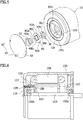
FIG. 3 is a cross-sectional view of a friction brake structure for a motor according to an embodiment of the present invention. -
FIG. 4 is a partial enlarged view ofFIG. 2 . -
FIG. 5 is an exploded perspective view of the friction brake structure. -
FIG. 6 is a cross-sectional view of a conventional friction brake structure for a motor. - First of all, the inventor made a study on mechanisms of abnormal noise production, which will be described in detail below.
-
FIG. 1 is a view illustrating thebrake plate 104 and the plurality ofbrake shoes 105 in the motor shown inFIG. 6 as viewed from the opposite-to-output side of the motor. InFIG. 1 , the fourbrake shoes 105, which are provided in the circumferential direction at even intervals, are denoted by thereference numerals 1051 to 1054 so as to be distinguishable from one another. The rotation direction of thebrake plate 104 is indicated by arrow A1. - Abnormal noise production in a friction brake structure is a kind of self-excited oscillation in a coupled system.
FIGS. 2A and 2B each show the coupled system including a portion of thebrake plate 104, thebrake shoe 1052, and thecoil spring 109 as viewed from the direction indicated by arrow Y ofFIG. 1 . The elasticity, mass, and position of thebrake plate 104 inFIGS. 2A and 2B are represented by kB, mB, and xB, respectively. Also, the elasticity, mass, and position of thebrake shoe 1052 inFIGS. 2A and 2B are represented by k, mS, and xS, respectively. The elasticity of thecoil spring 109 is represented by kS. InFIG. 2B , ϕ indicates an inclination angle of thebrake shoe 1052 observed when the portion of thebrake plate 104 has moved in the direction of arrow A2 as a result of the rotation of thebrake plate 104. The moment of inertia of thebrake shoe 1052 is represented by JS. The friction coefficient between thebrake plate 104 and thebrake shoe 1052 is represented by µ. The distance from the center of gravity G of thebrake shoe 1052 to the slidingcontact surface 105a is represented by l 0, and time is represented by t. The contact area between thebrake plate 104 and thebrake shoe 1052 is represented by A, and the spring constant related to the rotation around the center of gravity G of thebrake shoe 1052 is represented by kϕ. In the vicinity of the equilibrium point, these quantities have the following relationships:


- Equation (1) is the equation of motion for the position of the brake plate. Equation (2) is the equation of motion for the position of the brake shoe. Equation (3) is the equation of motion for the rotation of the brake shoe.
- Here, the integrand f(l) is a function expressing the pressure between the
brake plate 104 and thebrake shoe 1052, in which l represents the coordinates on the slidingcontact surface 105a in the case in which the point of intersection Q between the axis of thebrake shoe 1052 and the slidingcontact surface 105a is used as a reference point. The integrand f(l) can be approximated as follows:
- Combining the above equations gives the following simultaneous equations:

- Taking the Laplace transform of these simultaneous equations gives the following characteristic equation:

- In general, it is known that if the matrix in the above characteristic equation is symmetric, it indicates the system is not a self-excited oscillation system, but if any pair of elements given by switching the row and column indices have opposite signs, it indicates the system is a self-excited oscillation system. In the characteristic equation shown above, the elements related to the rotation of the brake shoe are not symmetric, and each may possibly have an opposite sign to an element given by switching the row and column indices. This indicates a possibility that self-excited oscillation of the brake shoes may be generated in the rotation direction, which causes abnormal noises.
- As described above, JPH11-089173A discloses that the brake shoes are fixed to the ring-shaped support. In such case, as the brake plate rotates, the brake shoes might rotate slightly with respect to the ring-shaped support, which causes self-excited oscillation, and thus abnormal noises.
- In light of the mechanisms of abnormal noise production described above, an embodiment of the present invention will be described below.
- As shown in
FIGS. 3 to 5 , amotor 1 has amotor case 10, which serves as a housing. In themotor case 10, astator 11 and arotor 12 are provided. Therotor 12 is supported by a rotatingshaft 15 supported on an output-side bearing 13 and an opposite-to-output-side bearing 14. - The opposite-to-output-
side bearing 14 is mounted in a bearinghousing portion 10a which is integrally provided to themotor case 10. In the bearinghousing portion 10a, ahole 10b is drilled in the axial direction so as to communicate with the outside of themotor case 10. Thehole 10b, which is approximately oval-shaped, has twoflat surface portions hole 10b has a so-called D-cut shape. - A ring-shaped
brake plate 20 is fixed to therotating shaft 15 at a location outside the opposite-to-output-side bearing 14. The rotatingshaft 15 passes through ahole 20a of thebrake plate 20. In addition, thebrake plate 20 is supported on aninner ring portion 14a of the opposite-to-output-side bearing 14. The outside diameter of thebrake plate 20 is smaller than the outside diameter of the opposite-to-output-side bearing 14. Thebrake plate 20 rotates together with the rotatingshaft 15. - A ring-shaped
brake shoe 30 is provided so as to face thebrake plate 20. The rotatingshaft 15 passes through ahole 30a of thebrake shoe 30. The outside diameter of thebrake shoe 30 is smaller than the outside diameter of the opposite-to-output-side bearing 14. Thebrake shoe 30 has fourprotrusions 30c in anaxial end surface 30b opposite to the other axial end surface being in sliding contact with thebrake plate 20. Theprotrusions 30c are provided in the circumferential direction at even intervals. Thebrake shoe 30 may be made of a material, such as a PPS (polyphenylene sulfide) resin or a PTFE (polytetrafluoroethylene) resin. - The
brake shoe 30 is supported by a ring-shaped brakeshoe support plate 40 which is movable in the axial direction. The rotatingshaft 15 passes through afirst hole 40a provided at the center of the brakeshoe support plate 40. - The brake
shoe support plate 40 has twoflat surface portions outer periphery 40b so as to face each other across thefirst hole 40a. These twoflat surface portions flat surface portions shoe support plate 40 has an approximately oval, so-called D-cut shape. The engagement of the twoflat surface portions shoe support plate 40 respectively with theflat surface portions shoe support plate 40 from rotating around the rotatingshaft 15 while allowing the brakeshoe support plate 40 to move in the axial direction. - In addition, the brake
shoe support plate 40 has foursecond holes 40c provided in the circumferential direction at even intervals so as to engage respectively with the fourprotrusions 30c. The engagement of the foursecond holes 40c respectively with the fourprotrusions 30c fixes thebrake shoe 30 onto the brakeshoe support plate 40. - A
conical coil spring 50 is disposed on the outside axial end surface, which is opposite to the surface supporting thebrake shoe 30, of the brakeshoe support plate 40. Theconical coil spring 50 is supported on a conical coilspring support plate 60 which is attached to themotor case 10 withscrews 61. The brakeshoe support plate 40 is biased by biasing action of theconical coil spring 50 so as to bring thebrake shoe 30 into sliding contact with thebrake plate 20. - Further, between the opposite-to-output-
side bearing 14 and an outerperipheral portion 40d of the brakeshoe support plate 40, acontact stop portion 10c is provided. The outerperipheral portion 40d is located radially outside thesecond holes 40c. Thecontact stop portion 10c protrudes radially inward from the inner wall of thehole 10b of the bearinghousing portion 10a. Thecontact stop portion 10c is provided in order to restrict the movement of the brakeshoe support plate 40 in the axial direction toward thebrake plate 20. Such movement is to occur when thebrake shoe 30 is worn by sliding contact with thebrake plate 20 enough to reduce the axial thickness of thebrake shoe 30 below a predetermined value. - As described above, the
brake shoe 30 is fixed to the brakeshoe support plate 40, which is prevented from rotating around the rotatingshaft 15 while being allowed to move in the axial direction. Thus, while themotor 1 is driven, thebrake shoe 30 is prevented from rotating along with the rotation of therotating shaft 15 and thebrake plate 20, which allows for braking the rotation of therotating shaft 15. When the drive of themotor 1 stops, the braking force of thebrake shoe 30 can quickly stop the rotation of therotating shaft 15. In addition, while the motor stops, a certain holding force for therotating shaft 15 is exerted. As described above, this embodiment provides braking action while the motor is driven as well as holding torque while the motor stops. - By bringing the
brake shoe 30, which has a ring shape allowing securing of a sufficient sliding contact area, into sliding contact with thebrake plate 20, thebrake shoe 30 is prevented from rotating together with thebrake plate 20. This reduces a rotational moment caused by a friction force of thebrake shoe 30, and thus makes the spring constant of the coupled portion between thebrake shoe 30 and thebrake plate 20 less liable to change. - Here, in each of Equations (4) to (6) expressing coupled oscillation, the first term on the right side expresses a restoring force that causes simple harmonic motion, and the coefficient of this term is the so-called spring constant. The inclination angle ϕ is included in the second or subsequent item, which brings the same effect as changes in the spring constant in the conventional technique shown in
FIG. 6 . - In contrast, according to the above embodiment, by making the spring constant of the coupled portion between the
brake shoe 30 and thebrake plate 20 less liable to change, self-excited oscillation of thebrake shoe 30 can be reduced, and thus production of abnormal noises called brake squeal can be reduced. - Such effect of reducing abnormal noise production will be described in relation to Equation (7). Note however that since it seems to be difficult to simply use Equation (7), which includes three variables, without any modifications, the determination on whether stable or not will be considered below by using a modified equation including two variables obtained by reducing the elements in Equation (7). Suppose such modified equation can be expressed as follows:

- It is known that when the product of off-diagonal elements is negative in this equation, it indicates that the system is a self-excited oscillation system.
- According to the above embodiment, the ring shape of the
brake shoe 30 allows thebrake shoe 30 to secure a sufficient sliding contact area, and thereby to prevent or reduce thebrake shoe 30 from rotating together with thebrake plate 20. In other words, unlike the conventional technique shown inFIG. 6 , the inclination angle ϕ is zero or infinitely close to zero in this embodiment. Excluding the equation of motion for the rotation of the brake shoe from Equation (7) gives the following equation:
- In Equation (9), the product of the two off-diagonal elements is positive, which indicates the system is not a self-excited oscillation system. This means that the above embodiment can reduce abnormal noise production in the brake.
- In contrast, regarding the conventional technique as shown in
FIG. 6 , excluding XB from Equation (7) gives the following equation:
- According to the conventional technique, because of the presence of the inclination angle ϕ, the following expression:
- Friction against the
brake plate 20 gradually wears thebrake shoe 30, and reduces the axial thickness of thebrake shoe 30. This thickness reduction moves the brakeshoe support plate 40, on which a biasing force is imposed by theconical coil spring 50, toward thebrake plate 20. The brakeshoe support plate 40 eventually comes into contact with thecontact stop portion 10c, which restricts the further movement of the brakeshoe support plate 40 toward thebrake plate 20. When thebrake shoe 30 is further worn, thebrake shoe 30 is no longer in sliding contact with thebrake plate 20. This prevents or reduces spark generation, which is expected to occur if thebrake shoe 30 is in such sliding contact even after being worn to some substantial extent. - In contrast, in
FIG. 6 , which is not provided with thecontact stop portion 10c, spark generation can be prevented or reduced by limiting the free height of thecoil spring 109 such that thecoil spring 109 is not compressed after thebrake shoes 105 have been substantially worn. However, in such case, as thebrake shoes 105 are worn, the compression height of thecoil spring 109 increases, and accordingly the biasing force of thecoil spring 109 decreases. This might lead to braking force reduction. - In the above embodiment, the presence of the
contact stop portion 10c eliminates the need of limiting such spring free height. This makes it possible to select, as theconical coil spring 50, a spring having a free height large enough to exert a sufficient biasing force before the brakeshoe support plate 40 comes into contact with thecontact stop portion 10c. Thus, the above embodiment can provide a reliable braking force before the brakeshoe support plate 40 comes into contact with thecontact stop portion 10c. - In
FIG. 6 , thebrake plate 104 is provided axially inside the opposite-to-output-side bearing 106b. Thebrake shoes 105 are disposed radially outside the opposite-to-output-side bearing 106b so as not to interfere with the opposite-to-output-side bearing 106b. As a result, thebrake plate 104 has a relatively large outside diameter. In other words, thebrake shoes 105 are brought into sliding contact with thebrake plate 104 at relatively distant points from the axis of therotating shaft 103. This inevitably increases the circumferential speed of the sliding contact portions to a relatively high value. - The wear volume of a brake shoe is proportional to the product PV of the contact pressure P [MPa] caused by the biasing force F of a spring and the circumferential speed V [m/s] at the sliding contact surface of the brake shoe. However, after the circumferential speed V increases to a certain value or more, the wear volume increases to a large value without being dependent on P any longer. This makes it difficult to prolong brake life in
FIG. 6 . - In the above embodiment, the outside diameters of the
brake plate 20 and thebrake shoe 30 are both smaller than the outside diameter of the opposite-to-output-side bearing 14. Thus, the sliding contact portion is relatively close to the axis of therotating shaft 15, which suppresses an increase in the circumferential speed V at the sliding contact portion. The closer to the axis the sliding contact portion is, the larger spring biasing force F is needed to provide a desirable braking force. However, in the above embodiment, the ring shape of thebrake shoe 30, which allows securing of a sufficient sliding contact area, limits the value taken by P. Therefore, the value of the product PV is reduced, and thus brake life can be prolonged. - Also, a single integrated brake shoe is provided instead of a plurality of brake shoes, and only one conical coil spring is provided as a biasing mechanism corresponding to the brake shoe. This allows for more efficient assembly.
- In addition, though providing the brake structure axially outside the opposite-to-output-side bearing is considered to increase the size of the motor in the axial direction, such size increase can be limited by employing the conical coil spring.
- In place of the
conical coil spring 50, any biasing mechanism such as an ordinary coil spring or any resilient mechanism may be provided. - The number of the
protrusions 30c is four in the above embodiment, but may be set to any number. It is only necessary to provide thesecond holes 40c as many as theprotrusions 30c. Thesecond holes 40c have only to be engaging portions for engaging with theprotrusions 30c, and may either penetrate through the brakeshoe support plate 40 from the support surface to its opposite surface, or do not penetrate to this opposite surface but instead form recesses. A still alternative configuration is also possible in which theprotrusions 30c are provided to the brakeshoe support plate 40 and thesecond holes 40c are provided to thebrake shoe 30. - The brake
shoe support plate 40 does not necessarily engage with the bearinghousing portion 10a, which is a fixing portion provided in themotor 1 and is not expected to be moved by driving themotor 1, but may engage with another fixing portion. - The friction brake structure may also be provided to a rotary electric machine other than the
motor 1. - Certain embodiments of a friction brake structure have been specifically described above. However, the present invention is not limited to such embodiments, and any modifications and alterations obvious to those skilled in the art will be all included within the technical scope of the appending claims.
-
- 1
- motor
- 10
- motor case
- 10a
- bearing housing portion
- 10b
- hole
- 10b1
- flat surface portion
- 10b2
- flat surface portion
- 10c
- contact stop portion
- 11
- stator
- 12
- rotor
- 13
- output-side bearing
- 14
- opposite-to-output-side bearing
- 14a
- inner ring portion
- 15
- rotating shaft
- 20
- brake plate
- 20a
- hole
- 30
- brake shoe
- 30a
- hole
- 30b
- axial end surface
- 30c
- protrusion
- 40
- brake shoe support plate
- 40a
- first hole
- 40b
- outer periphery
- 40b1
- flat surface portion
- 40b2
- flat surface portion
- 40c
- second hole
- 40d
- outer peripheral portion
- 50
- conical coil spring
- 60
- conical coil spring support plate
- 61
- screw
- 100
- motor case
- 101
- stator
- 102
- rotor
- 103
- rotating shaft
- 104
- brake plate
- 105
- brake shoe
- 1051 to 1054
- brake shoe
- 105a
- sliding contact surface
- 106a
- output-side bearing
- 106b
- opposite-to-output-side bearing
- 107
- bearing housing portion
- 108
- hole
- 109
- coil spring
- 110
- spring retainer plate
- G
- center of gravity
- ϕ
- inclination angle
- l 0
- length
- l
- coordinate
- Q
- point of intersection
- A1, A2, Y
- arrow
Claims (7)
- A friction brake structure comprising:a brake plate (20) fixed to a rotating shaft (15) of a rotary electric machine (1);a ring-shaped brake shoe (30) disposed facing the brake plate (20); anda brake shoe support plate (40) which engages with a fixing portion of the rotary electric machine (1) so as to be movable in an axial direction, and which supports the brake shoe (30) while being biased by biasing action so as to bring the brake shoe (30) into sliding contact with the brake plate (20); the brake shoe (30) and the brake shoe support plate (40) arranged to exert a holding torque on the rotating shaft (15) of the rotary electric machine (1) while the rotary electric machine stops;characterized in that the brake shoe (30) and the brake shoe support plate (40) are arranged to exert a braking action on the rotating shaft (15) of the rotary electric machine (1) while the rotary electric machine (1) is driven.
- The friction brake structure according to claim 1, wherein a protrusion (30c) is provided in either one of a surface of the brake shoe opposite to a sliding contact surface with the brake plate, and a support surface of the brake shoe support plate, and an engaging portion for engaging with the protrusion is provided in the other one.
- The friction brake structure according to claim 1, wherein the brake plate is fixed to the rotating shaft at a location outside an opposite-to-output-side bearing (14) for supporting the rotating shaft.
- The friction brake structure according to claim 3, wherein
an outside diameter of the brake plate is smaller than an outside diameter of the opposite-to-output-side bearing, and
the brake plate is supported on an inner ring portion (14a) of the opposite-to-output-side bearing. - The friction brake structure according to claim 3, wherein an outside diameter of the brake shoe is smaller than an outside diameter of the opposite-to-output-side bearing.
- The friction brake structure according to claim 1, further comprising a conical coil spring (50) as a mechanism for applying the biasing action to the brake shoe support plate.
- The friction brake structure according to claim 1, further comprising a contact stop portion (10c) for restricting movement of the brake shoe support plate in the axial direction toward the brake plate, the movement occurring when an axial thickness of the brake shoe reduces below a predetermined value.
Applications Claiming Priority (2)
| Application Number | Priority Date | Filing Date | Title |
|---|---|---|---|
| JP2014265847A JP6339933B2 (en) | 2014-12-26 | 2014-12-26 | Friction brake structure |
| PCT/JP2015/085699 WO2016104438A1 (en) | 2014-12-26 | 2015-12-21 | Friction brake structure |
Publications (3)
| Publication Number | Publication Date |
|---|---|
| EP3239552A1 EP3239552A1 (en) | 2017-11-01 |
| EP3239552A4 EP3239552A4 (en) | 2018-11-21 |
| EP3239552B1 true EP3239552B1 (en) | 2019-11-06 |
Family
ID=56150457
Family Applications (1)
| Application Number | Title | Priority Date | Filing Date |
|---|---|---|---|
| EP15873006.9A Active EP3239552B1 (en) | 2014-12-26 | 2015-12-21 | Friction brake structure |
Country Status (7)
| Country | Link |
|---|---|
| US (1) | US10598235B2 (en) |
| EP (1) | EP3239552B1 (en) |
| JP (1) | JP6339933B2 (en) |
| KR (1) | KR102437405B1 (en) |
| CN (1) | CN107110257B (en) |
| TW (1) | TWI671477B (en) |
| WO (1) | WO2016104438A1 (en) |
Families Citing this family (2)
| Publication number | Priority date | Publication date | Assignee | Title |
|---|---|---|---|---|
| US11411464B2 (en) * | 2015-07-28 | 2022-08-09 | Dewertokin Technology Group Co., Ltd. | Braking device for an electric drive motor |
| KR102487166B1 (en) * | 2016-11-23 | 2023-01-10 | 현대자동차 주식회사 | Resolver mounting structure for motor |
Family Cites Families (23)
| Publication number | Priority date | Publication date | Assignee | Title |
|---|---|---|---|---|
| DE1243926B (en) | 1962-09-15 | 1967-07-06 | Ferodo Sa | Brake pad for partially lined disc brakes |
| FR2135689A5 (en) * | 1971-03-09 | 1972-12-22 | Potain Sa | |
| US3667578A (en) * | 1971-05-14 | 1972-06-06 | Harold Beck & Sons Inc | Bi-directional drive released brake |
| DE2625990C2 (en) | 1976-06-10 | 1984-09-06 | Karl-Ernst 4924 Barntrup Brinkmann | Electromagnetically released spring pressure brake |
| JPS55135237A (en) * | 1979-04-06 | 1980-10-21 | Toyota Motor Corp | Disk brake |
| US4289216A (en) * | 1979-04-06 | 1981-09-15 | Toyota Jidosha Kogyo Kabushiki | Disc brake |
| JPS56109934A (en) * | 1980-02-04 | 1981-08-31 | Toyota Motor Corp | Disc brake |
| JPS587935A (en) | 1981-07-07 | 1983-01-17 | Kokusai Denshin Denwa Co Ltd <Kdd> | Transversal type smear/desmear filter |
| JPS587935U (en) * | 1981-07-09 | 1983-01-19 | 特殊精工株式会社 | Spring brake electromagnetic brake |
| JPS5882417U (en) * | 1981-11-29 | 1983-06-03 | 日野自動車株式会社 | Blow-by gas control device |
| JPS59186535A (en) | 1983-04-07 | 1984-10-23 | 東芝テック株式会社 | Electric cleaner |
| JPS59186535U (en) * | 1983-05-31 | 1984-12-11 | 三菱電機株式会社 | Brake release mechanism |
| EP0209943B1 (en) * | 1985-07-26 | 1992-11-11 | Mavilor Systèmes S.A. | Electric motor with a disc brake |
| CA2112609A1 (en) * | 1993-12-30 | 1995-07-01 | Eddy Desrochers | Combination brake and clutch assembly for electric motors |
| JPH0940339A (en) * | 1995-08-02 | 1997-02-10 | Mitsubishi Denki Bill Techno Service Kk | Brake slippage preventing device when escalator is suspended |
| SE505313C2 (en) * | 1996-05-31 | 1997-08-04 | Fhp Elmotor Ab | Braking |
| JPH1189173A (en) | 1997-09-02 | 1999-03-30 | Oriental Motor Co Ltd | Friction brake structure of motor |
| US5967272A (en) | 1998-02-27 | 1999-10-19 | Eaton Corporation | Clutch brake wear limiter |
| JP2002051528A (en) | 2000-07-31 | 2002-02-15 | Minebea Co Ltd | Stepping motor |
| FR2834391B1 (en) * | 2001-12-28 | 2004-04-02 | Somfy | DISC BRAKE AND TORQUE TRANSMISSION DEVICE |
| US8820489B2 (en) * | 2007-03-07 | 2014-09-02 | Arvinmeritor Technology, Llc | Electric motor with static brake |
| JP2012122574A (en) * | 2010-12-10 | 2012-06-28 | Hitachi Industrial Equipment Systems Co Ltd | Electromagnetic brake and electric motor |
| FR3023656B1 (en) * | 2014-07-08 | 2016-08-05 | Sagem Defense Securite | ELECTROMECHANICAL ACTUATOR WITH DOUBLE-FUNCTION BRAKING DEVICE |
-
2014
- 2014-12-26 JP JP2014265847A patent/JP6339933B2/en active Active
-
2015
- 2015-12-21 KR KR1020177016344A patent/KR102437405B1/en active Active
- 2015-12-21 CN CN201580069685.8A patent/CN107110257B/en active Active
- 2015-12-21 US US15/539,842 patent/US10598235B2/en active Active
- 2015-12-21 WO PCT/JP2015/085699 patent/WO2016104438A1/en not_active Ceased
- 2015-12-21 EP EP15873006.9A patent/EP3239552B1/en active Active
- 2015-12-24 TW TW104143568A patent/TWI671477B/en active
Non-Patent Citations (1)
| Title |
|---|
| None * |
Also Published As
| Publication number | Publication date |
|---|---|
| KR20170099887A (en) | 2017-09-01 |
| US10598235B2 (en) | 2020-03-24 |
| CN107110257B (en) | 2019-05-17 |
| JP2016125572A (en) | 2016-07-11 |
| KR102437405B1 (en) | 2022-08-29 |
| JP6339933B2 (en) | 2018-06-06 |
| TW201631265A (en) | 2016-09-01 |
| CN107110257A (en) | 2017-08-29 |
| TWI671477B (en) | 2019-09-11 |
| EP3239552A1 (en) | 2017-11-01 |
| WO2016104438A1 (en) | 2016-06-30 |
| US20170370429A1 (en) | 2017-12-28 |
| EP3239552A4 (en) | 2018-11-21 |
Similar Documents
| Publication | Publication Date | Title |
|---|---|---|
| US11300170B2 (en) | Spreader unit for a drum brake, comprising wear travel adjustment, and the drum brake | |
| US20080053719A1 (en) | Brake structure for wheel rotating device | |
| US10563701B2 (en) | Methods and apparatus for clutch and brake drag reduction using springs | |
| EP2840278A1 (en) | Friction brake device | |
| EP3239552B1 (en) | Friction brake structure | |
| WO2015198682A1 (en) | Disc brake | |
| CN205047764U (en) | Deceleration device | |
| KR101221123B1 (en) | Electric brake motor | |
| JP6081166B2 (en) | Disc brake device | |
| JP2010144852A (en) | Spring actuated electromagnetic brake and motor equipped therewith | |
| JP4054818B2 (en) | Centrifugal clutch device | |
| US9920798B2 (en) | Braking device | |
| JP2018162840A (en) | Vehicle brake | |
| US20180180120A1 (en) | Brake module | |
| JP2010048363A (en) | Brake caliper | |
| CN215950198U (en) | Centrifugal brake and appliance with rotary body | |
| WO2016042929A1 (en) | Centrifugal-type clutch device | |
| JP2007024255A (en) | Centrifugal clutch device | |
| CN111628609B (en) | Brake device and power assembly | |
| KR100994009B1 (en) | Disc brake | |
| KR101462081B1 (en) | Braking unit for a wheelchair | |
| GB2588786A (en) | Static brake assembly | |
| JP2017036742A (en) | Braking device | |
| JP2020034148A (en) | Vehicular brake | |
| JP2017061967A (en) | Pulley device |
Legal Events
| Date | Code | Title | Description |
|---|---|---|---|
| STAA | Information on the status of an ep patent application or granted ep patent |
Free format text: STATUS: THE INTERNATIONAL PUBLICATION HAS BEEN MADE |
|
| PUAI | Public reference made under article 153(3) epc to a published international application that has entered the european phase |
Free format text: ORIGINAL CODE: 0009012 |
|
| STAA | Information on the status of an ep patent application or granted ep patent |
Free format text: STATUS: REQUEST FOR EXAMINATION WAS MADE |
|
| 17P | Request for examination filed |
Effective date: 20170626 |
|
| AK | Designated contracting states |
Kind code of ref document: A1 Designated state(s): AL AT BE BG CH CY CZ DE DK EE ES FI FR GB GR HR HU IE IS IT LI LT LU LV MC MK MT NL NO PL PT RO RS SE SI SK SM TR |
|
| AX | Request for extension of the european patent |
Extension state: BA ME |
|
| DAV | Request for validation of the european patent (deleted) | ||
| DAX | Request for extension of the european patent (deleted) | ||
| A4 | Supplementary search report drawn up and despatched |
Effective date: 20181019 |
|
| RIC1 | Information provided on ipc code assigned before grant |
Ipc: F16D 55/02 20060101AFI20181015BHEP Ipc: F16D 65/097 20060101ALI20181015BHEP Ipc: H02K 7/102 20060101ALI20181015BHEP |
|
| GRAP | Despatch of communication of intention to grant a patent |
Free format text: ORIGINAL CODE: EPIDOSNIGR1 |
|
| STAA | Information on the status of an ep patent application or granted ep patent |
Free format text: STATUS: GRANT OF PATENT IS INTENDED |
|
| INTG | Intention to grant announced |
Effective date: 20190712 |
|
| GRAS | Grant fee paid |
Free format text: ORIGINAL CODE: EPIDOSNIGR3 |
|
| GRAA | (expected) grant |
Free format text: ORIGINAL CODE: 0009210 |
|
| STAA | Information on the status of an ep patent application or granted ep patent |
Free format text: STATUS: THE PATENT HAS BEEN GRANTED |
|
| AK | Designated contracting states |
Kind code of ref document: B1 Designated state(s): AL AT BE BG CH CY CZ DE DK EE ES FI FR GB GR HR HU IE IS IT LI LT LU LV MC MK MT NL NO PL PT RO RS SE SI SK SM TR |
|
| REG | Reference to a national code |
Ref country code: GB Ref legal event code: FG4D |
|
| REG | Reference to a national code |
Ref country code: CH Ref legal event code: EP Ref country code: AT Ref legal event code: REF Ref document number: 1199118 Country of ref document: AT Kind code of ref document: T Effective date: 20191115 |
|
| REG | Reference to a national code |
Ref country code: IE Ref legal event code: FG4D |
|
| REG | Reference to a national code |
Ref country code: DE Ref legal event code: R096 Ref document number: 602015041406 Country of ref document: DE |
|
| REG | Reference to a national code |
Ref country code: NL Ref legal event code: MP Effective date: 20191106 |
|
| REG | Reference to a national code |
Ref country code: LT Ref legal event code: MG4D |
|
| PG25 | Lapsed in a contracting state [announced via postgrant information from national office to epo] |
Ref country code: NO Free format text: LAPSE BECAUSE OF FAILURE TO SUBMIT A TRANSLATION OF THE DESCRIPTION OR TO PAY THE FEE WITHIN THE PRESCRIBED TIME-LIMIT Effective date: 20200206 Ref country code: PT Free format text: LAPSE BECAUSE OF FAILURE TO SUBMIT A TRANSLATION OF THE DESCRIPTION OR TO PAY THE FEE WITHIN THE PRESCRIBED TIME-LIMIT Effective date: 20200306 Ref country code: LT Free format text: LAPSE BECAUSE OF FAILURE TO SUBMIT A TRANSLATION OF THE DESCRIPTION OR TO PAY THE FEE WITHIN THE PRESCRIBED TIME-LIMIT Effective date: 20191106 Ref country code: PL Free format text: LAPSE BECAUSE OF FAILURE TO SUBMIT A TRANSLATION OF THE DESCRIPTION OR TO PAY THE FEE WITHIN THE PRESCRIBED TIME-LIMIT Effective date: 20191106 Ref country code: GR Free format text: LAPSE BECAUSE OF FAILURE TO SUBMIT A TRANSLATION OF THE DESCRIPTION OR TO PAY THE FEE WITHIN THE PRESCRIBED TIME-LIMIT Effective date: 20200207 Ref country code: NL Free format text: LAPSE BECAUSE OF FAILURE TO SUBMIT A TRANSLATION OF THE DESCRIPTION OR TO PAY THE FEE WITHIN THE PRESCRIBED TIME-LIMIT Effective date: 20191106 Ref country code: SE Free format text: LAPSE BECAUSE OF FAILURE TO SUBMIT A TRANSLATION OF THE DESCRIPTION OR TO PAY THE FEE WITHIN THE PRESCRIBED TIME-LIMIT Effective date: 20191106 Ref country code: LV Free format text: LAPSE BECAUSE OF FAILURE TO SUBMIT A TRANSLATION OF THE DESCRIPTION OR TO PAY THE FEE WITHIN THE PRESCRIBED TIME-LIMIT Effective date: 20191106 Ref country code: FI Free format text: LAPSE BECAUSE OF FAILURE TO SUBMIT A TRANSLATION OF THE DESCRIPTION OR TO PAY THE FEE WITHIN THE PRESCRIBED TIME-LIMIT Effective date: 20191106 Ref country code: BG Free format text: LAPSE BECAUSE OF FAILURE TO SUBMIT A TRANSLATION OF THE DESCRIPTION OR TO PAY THE FEE WITHIN THE PRESCRIBED TIME-LIMIT Effective date: 20200206 |
|
| PG25 | Lapsed in a contracting state [announced via postgrant information from national office to epo] |
Ref country code: RS Free format text: LAPSE BECAUSE OF FAILURE TO SUBMIT A TRANSLATION OF THE DESCRIPTION OR TO PAY THE FEE WITHIN THE PRESCRIBED TIME-LIMIT Effective date: 20191106 Ref country code: HR Free format text: LAPSE BECAUSE OF FAILURE TO SUBMIT A TRANSLATION OF THE DESCRIPTION OR TO PAY THE FEE WITHIN THE PRESCRIBED TIME-LIMIT Effective date: 20191106 Ref country code: IS Free format text: LAPSE BECAUSE OF FAILURE TO SUBMIT A TRANSLATION OF THE DESCRIPTION OR TO PAY THE FEE WITHIN THE PRESCRIBED TIME-LIMIT Effective date: 20200306 |
|
| PG25 | Lapsed in a contracting state [announced via postgrant information from national office to epo] |
Ref country code: AL Free format text: LAPSE BECAUSE OF FAILURE TO SUBMIT A TRANSLATION OF THE DESCRIPTION OR TO PAY THE FEE WITHIN THE PRESCRIBED TIME-LIMIT Effective date: 20191106 |
|
| PG25 | Lapsed in a contracting state [announced via postgrant information from national office to epo] |
Ref country code: DK Free format text: LAPSE BECAUSE OF FAILURE TO SUBMIT A TRANSLATION OF THE DESCRIPTION OR TO PAY THE FEE WITHIN THE PRESCRIBED TIME-LIMIT Effective date: 20191106 Ref country code: EE Free format text: LAPSE BECAUSE OF FAILURE TO SUBMIT A TRANSLATION OF THE DESCRIPTION OR TO PAY THE FEE WITHIN THE PRESCRIBED TIME-LIMIT Effective date: 20191106 Ref country code: RO Free format text: LAPSE BECAUSE OF FAILURE TO SUBMIT A TRANSLATION OF THE DESCRIPTION OR TO PAY THE FEE WITHIN THE PRESCRIBED TIME-LIMIT Effective date: 20191106 Ref country code: CZ Free format text: LAPSE BECAUSE OF FAILURE TO SUBMIT A TRANSLATION OF THE DESCRIPTION OR TO PAY THE FEE WITHIN THE PRESCRIBED TIME-LIMIT Effective date: 20191106 |
|
| REG | Reference to a national code |
Ref country code: CH Ref legal event code: PL |
|
| REG | Reference to a national code |
Ref country code: DE Ref legal event code: R097 Ref document number: 602015041406 Country of ref document: DE |
|
| REG | Reference to a national code |
Ref country code: AT Ref legal event code: MK05 Ref document number: 1199118 Country of ref document: AT Kind code of ref document: T Effective date: 20191106 |
|
| REG | Reference to a national code |
Ref country code: BE Ref legal event code: MM Effective date: 20191231 |
|
| PG25 | Lapsed in a contracting state [announced via postgrant information from national office to epo] |
Ref country code: SM Free format text: LAPSE BECAUSE OF FAILURE TO SUBMIT A TRANSLATION OF THE DESCRIPTION OR TO PAY THE FEE WITHIN THE PRESCRIBED TIME-LIMIT Effective date: 20191106 Ref country code: MC Free format text: LAPSE BECAUSE OF FAILURE TO SUBMIT A TRANSLATION OF THE DESCRIPTION OR TO PAY THE FEE WITHIN THE PRESCRIBED TIME-LIMIT Effective date: 20191106 Ref country code: SK Free format text: LAPSE BECAUSE OF FAILURE TO SUBMIT A TRANSLATION OF THE DESCRIPTION OR TO PAY THE FEE WITHIN THE PRESCRIBED TIME-LIMIT Effective date: 20191106 |
|
| PLBE | No opposition filed within time limit |
Free format text: ORIGINAL CODE: 0009261 |
|
| STAA | Information on the status of an ep patent application or granted ep patent |
Free format text: STATUS: NO OPPOSITION FILED WITHIN TIME LIMIT |
|
| 26N | No opposition filed |
Effective date: 20200807 |
|
| PG25 | Lapsed in a contracting state [announced via postgrant information from national office to epo] |
Ref country code: LU Free format text: LAPSE BECAUSE OF NON-PAYMENT OF DUE FEES Effective date: 20191221 Ref country code: IE Free format text: LAPSE BECAUSE OF NON-PAYMENT OF DUE FEES Effective date: 20191221 Ref country code: ES Free format text: LAPSE BECAUSE OF FAILURE TO SUBMIT A TRANSLATION OF THE DESCRIPTION OR TO PAY THE FEE WITHIN THE PRESCRIBED TIME-LIMIT Effective date: 20191106 |
|
| PG25 | Lapsed in a contracting state [announced via postgrant information from national office to epo] |
Ref country code: BE Free format text: LAPSE BECAUSE OF NON-PAYMENT OF DUE FEES Effective date: 20191231 Ref country code: LI Free format text: LAPSE BECAUSE OF NON-PAYMENT OF DUE FEES Effective date: 20191231 Ref country code: CH Free format text: LAPSE BECAUSE OF NON-PAYMENT OF DUE FEES Effective date: 20191231 Ref country code: SI Free format text: LAPSE BECAUSE OF FAILURE TO SUBMIT A TRANSLATION OF THE DESCRIPTION OR TO PAY THE FEE WITHIN THE PRESCRIBED TIME-LIMIT Effective date: 20191106 Ref country code: AT Free format text: LAPSE BECAUSE OF FAILURE TO SUBMIT A TRANSLATION OF THE DESCRIPTION OR TO PAY THE FEE WITHIN THE PRESCRIBED TIME-LIMIT Effective date: 20191106 |
|
| PG25 | Lapsed in a contracting state [announced via postgrant information from national office to epo] |
Ref country code: IT Free format text: LAPSE BECAUSE OF FAILURE TO SUBMIT A TRANSLATION OF THE DESCRIPTION OR TO PAY THE FEE WITHIN THE PRESCRIBED TIME-LIMIT Effective date: 20191106 |
|
| PG25 | Lapsed in a contracting state [announced via postgrant information from national office to epo] |
Ref country code: CY Free format text: LAPSE BECAUSE OF FAILURE TO SUBMIT A TRANSLATION OF THE DESCRIPTION OR TO PAY THE FEE WITHIN THE PRESCRIBED TIME-LIMIT Effective date: 20191106 |
|
| PG25 | Lapsed in a contracting state [announced via postgrant information from national office to epo] |
Ref country code: HU Free format text: LAPSE BECAUSE OF FAILURE TO SUBMIT A TRANSLATION OF THE DESCRIPTION OR TO PAY THE FEE WITHIN THE PRESCRIBED TIME-LIMIT; INVALID AB INITIO Effective date: 20151221 Ref country code: MT Free format text: LAPSE BECAUSE OF FAILURE TO SUBMIT A TRANSLATION OF THE DESCRIPTION OR TO PAY THE FEE WITHIN THE PRESCRIBED TIME-LIMIT Effective date: 20191106 |
|
| PG25 | Lapsed in a contracting state [announced via postgrant information from national office to epo] |
Ref country code: TR Free format text: LAPSE BECAUSE OF FAILURE TO SUBMIT A TRANSLATION OF THE DESCRIPTION OR TO PAY THE FEE WITHIN THE PRESCRIBED TIME-LIMIT Effective date: 20191106 |
|
| PG25 | Lapsed in a contracting state [announced via postgrant information from national office to epo] |
Ref country code: MK Free format text: LAPSE BECAUSE OF FAILURE TO SUBMIT A TRANSLATION OF THE DESCRIPTION OR TO PAY THE FEE WITHIN THE PRESCRIBED TIME-LIMIT Effective date: 20191106 |
|
| PGFP | Annual fee paid to national office [announced via postgrant information from national office to epo] |
Ref country code: DE Payment date: 20251211 Year of fee payment: 11 |
|
| PGFP | Annual fee paid to national office [announced via postgrant information from national office to epo] |
Ref country code: GB Payment date: 20251219 Year of fee payment: 11 |
|
| PGFP | Annual fee paid to national office [announced via postgrant information from national office to epo] |
Ref country code: FR Payment date: 20251229 Year of fee payment: 11 |