EP3239104B1 - Energiesparendes meerwasserentsalzungssystem unter verwendung von dampf, der in einem kernreaktor erzeugt wurde, und verfahren zur entsalzung von meerwasser - Google Patents
Energiesparendes meerwasserentsalzungssystem unter verwendung von dampf, der in einem kernreaktor erzeugt wurde, und verfahren zur entsalzung von meerwasser Download PDFInfo
- Publication number
- EP3239104B1 EP3239104B1 EP14909165.4A EP14909165A EP3239104B1 EP 3239104 B1 EP3239104 B1 EP 3239104B1 EP 14909165 A EP14909165 A EP 14909165A EP 3239104 B1 EP3239104 B1 EP 3239104B1
- Authority
- EP
- European Patent Office
- Prior art keywords
- steam
- seawater
- heat exchanger
- supplied
- pressure turbine
- Prior art date
- Legal status (The legal status is an assumption and is not a legal conclusion. Google has not performed a legal analysis and makes no representation as to the accuracy of the status listed.)
- Active
Links
Images


Classifications
-
- B—PERFORMING OPERATIONS; TRANSPORTING
- B01—PHYSICAL OR CHEMICAL PROCESSES OR APPARATUS IN GENERAL
- B01D—SEPARATION
- B01D5/00—Condensation of vapours; Recovering volatile solvents by condensation
- B01D5/0078—Condensation of vapours; Recovering volatile solvents by condensation characterised by auxiliary systems or arrangements
-
- B—PERFORMING OPERATIONS; TRANSPORTING
- B01—PHYSICAL OR CHEMICAL PROCESSES OR APPARATUS IN GENERAL
- B01D—SEPARATION
- B01D1/00—Evaporating
- B01D1/0011—Heating features
- B01D1/0058—Use of waste energy from other processes or sources, e.g. combustion gas
-
- B—PERFORMING OPERATIONS; TRANSPORTING
- B01—PHYSICAL OR CHEMICAL PROCESSES OR APPARATUS IN GENERAL
- B01D—SEPARATION
- B01D1/00—Evaporating
- B01D1/28—Evaporating with vapour compression
- B01D1/284—Special features relating to the compressed vapour
- B01D1/2856—The compressed vapour is used for heating a reboiler or a heat exchanger outside an evaporator
-
- B—PERFORMING OPERATIONS; TRANSPORTING
- B01—PHYSICAL OR CHEMICAL PROCESSES OR APPARATUS IN GENERAL
- B01D—SEPARATION
- B01D5/00—Condensation of vapours; Recovering volatile solvents by condensation
- B01D5/0057—Condensation of vapours; Recovering volatile solvents by condensation in combination with other processes
- B01D5/0075—Condensation of vapours; Recovering volatile solvents by condensation in combination with other processes with heat exchanging
-
- C—CHEMISTRY; METALLURGY
- C02—TREATMENT OF WATER, WASTE WATER, SEWAGE, OR SLUDGE
- C02F—TREATMENT OF WATER, WASTE WATER, SEWAGE, OR SLUDGE
- C02F1/00—Treatment of water, waste water, or sewage
- C02F1/02—Treatment of water, waste water, or sewage by heating
- C02F1/04—Treatment of water, waste water, or sewage by heating by distillation or evaporation
- C02F1/16—Treatment of water, waste water, or sewage by heating by distillation or evaporation using waste heat from other processes
-
- F—MECHANICAL ENGINEERING; LIGHTING; HEATING; WEAPONS; BLASTING
- F01—MACHINES OR ENGINES IN GENERAL; ENGINE PLANTS IN GENERAL; STEAM ENGINES
- F01K—STEAM ENGINE PLANTS; STEAM ACCUMULATORS; ENGINE PLANTS NOT OTHERWISE PROVIDED FOR; ENGINES USING SPECIAL WORKING FLUIDS OR CYCLES
- F01K17/00—Using steam or condensate extracted or exhausted from steam engine plant
- F01K17/04—Using steam or condensate extracted or exhausted from steam engine plant for specific purposes other than heating
-
- C—CHEMISTRY; METALLURGY
- C02—TREATMENT OF WATER, WASTE WATER, SEWAGE, OR SLUDGE
- C02F—TREATMENT OF WATER, WASTE WATER, SEWAGE, OR SLUDGE
- C02F2103/00—Nature of the water, waste water, sewage or sludge to be treated
- C02F2103/08—Seawater, e.g. for desalination
-
- C—CHEMISTRY; METALLURGY
- C02—TREATMENT OF WATER, WASTE WATER, SEWAGE, OR SLUDGE
- C02F—TREATMENT OF WATER, WASTE WATER, SEWAGE, OR SLUDGE
- C02F2303/00—Specific treatment goals
- C02F2303/10—Energy recovery
-
- Y—GENERAL TAGGING OF NEW TECHNOLOGICAL DEVELOPMENTS; GENERAL TAGGING OF CROSS-SECTIONAL TECHNOLOGIES SPANNING OVER SEVERAL SECTIONS OF THE IPC; TECHNICAL SUBJECTS COVERED BY FORMER USPC CROSS-REFERENCE ART COLLECTIONS [XRACs] AND DIGESTS
- Y02—TECHNOLOGIES OR APPLICATIONS FOR MITIGATION OR ADAPTATION AGAINST CLIMATE CHANGE
- Y02A—TECHNOLOGIES FOR ADAPTATION TO CLIMATE CHANGE
- Y02A20/00—Water conservation; Efficient water supply; Efficient water use
- Y02A20/124—Water desalination
-
- Y—GENERAL TAGGING OF NEW TECHNOLOGICAL DEVELOPMENTS; GENERAL TAGGING OF CROSS-SECTIONAL TECHNOLOGIES SPANNING OVER SEVERAL SECTIONS OF THE IPC; TECHNICAL SUBJECTS COVERED BY FORMER USPC CROSS-REFERENCE ART COLLECTIONS [XRACs] AND DIGESTS
- Y02—TECHNOLOGIES OR APPLICATIONS FOR MITIGATION OR ADAPTATION AGAINST CLIMATE CHANGE
- Y02W—CLIMATE CHANGE MITIGATION TECHNOLOGIES RELATED TO WASTEWATER TREATMENT OR WASTE MANAGEMENT
- Y02W10/00—Technologies for wastewater treatment
- Y02W10/30—Wastewater or sewage treatment systems using renewable energies
Definitions
- the present disclosure relates to a seawater desalination system using steam generated in a nuclear reactor, and more particularly, to a seawater desalination system which improves energy efficiency by applying heated cooling water discharged from a nuclear power plant and high-temperature steam generated in a nuclear reactor to seawater desalination.
- Nuclear power generation refers to an apparatus using nuclear fission occurring in a nuclear reactor. That is, the nuclear power generation refers to an apparatus wherein nuclear fission takes place by causing neutrons to collide with uranium nuclei, and converts heat resulting from nuclear fission into electric power.
- the nuclear power plant requires a large amount of initial construction costs in comparison with other power generation methods, but has advantages in that power generation cost is low in view of cheap fuel cost. Furthermore, it is environmentally friendly because the nuclear power plant emits an extremely small amount of greenhouse gases. However, there are drawbacks in that radiation generated during a power generation process is detrimental to the environment or human bodies, and there still remain social issues and problems related to the storage and/or final disposal of high-level radioactive waste, and there are concerns about nuclear power plant accidents.
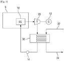
- Fig. 1 schematically illustrates a nuclear power generation process in the related art.
- a nuclear power generation system includes a nuclear reactor 6, a steam generator 10, a turbine 20, a condenser 30, and the like.
- Heat generated by nuclear fission in the reactor 6 is transferred to the steam generator 10 that produces high-temperature and high-pressure steam by using the transferred heat.
- the steam produced at the steam generator 10 is supplied into the turbine 20, and an electric generator 12 connected to the turbine 20 produces electricity.
- the steam used to produce electricity in the turbine 20 is supplied to the condenser 30.
- An inlet pipe 32 is installed to the condenser 30 such that seawater is introduced into the condenser 30, and a discharge pipe 34 is installed to the condenser 30 such that the introduced seawater is discharged back to the outside.
- the condenser 30 produces condensate water by liquefying the steam discharged from the turbine 20.
- the seawater which is introduced into the inlet pipe 32, may be used to liquefy the steam because the seawater is cold.
- the temperature of the seawater used to liquefy the steam is high, and the seawater is discharged to the discharge pipe 34.
- the temperature of the seawater used to liquefy the steam is increased by about 9 to 10°C.
- the seawater at temperature of 25°C is introduced into the inlet pipe 32
- the seawater, which has been used for the liquefaction process is discharged to the discharge pipe 34 at higher temperature of about 35°C.
- the condensate water produced in the condenser 30 is supplied back to the steam generator 10 by a circulation pump 14, and the steam generator 10 produces steam by using heat generated by nuclear fission.
- high-temperature seawater is discharged in the related art.
- the high-temperature seawater may adversely affect an environment and an ecosystem, and thus may be restricted by environmental regulations.
- the discharged high-temperature seawater is mixed with cold seawater supplied from the deep sea, and then the seawater is discharged.
- this solution is not preferred because there are problems of complicated process and increased cost to be incurred.
- the high-temperature seawater discharged from the nuclear power plant is used in a desalination factory.
- the seawater needs to be heated to a temperature of 100°C or higher in the desalination factory, and in a case in which the high-temperature seawater discharged from the nuclear power plant is used, energy required to heat the seawater may be saved as much as the amount of increased high-temperature seawater.
- CN102616875 discloses a method for performing seawater desalination by utilizing residual heat in thermal discharge of a power station.
- GB1268897 , CN203545714 , JPS5290472 and WO2011/148422 also disclose systems for seawater desalination.
- the present disclosure has been made in an effort to solve the aforementioned problems in the related art, and an object of the present disclosure is to provide a user with a seawater desalination system capable of improving energy efficiency by applying heated seawater discharged from a nuclear power plant and high-temperature steam generated in a nuclear reactor to seawater desalination.
- the present disclosure has also been made in an effort to provide a user with a seawater desalination system which is configured such that high-temperature seawater, which is discharged when steam is condensed in nuclear power plant, is supplied to a fresh water-generating unit, such that it is possible to save a considerable amount of energy to be used to produce fresh water, and to mitigate the ecological burden due to the emission of high-temperature seawater.
- the present disclosure has also been made in an effort to provide users with a seawater desalination system in which a part of steam discharged from turbine is used for heat exchange with seawater, and the heat exchange is performed by two steps, such that it is possible to produce high-temperature seawater sufficient to produce fresh water without additional energy consumption.
- the present disclosure has also been made in an effort to provide a user with a seawater desalination system capable of improving thermal efficiency by supplying steam used for heat exchange with seawater back to the circulation cycle of nuclear power plant.
- a method of desalinating seawater is also provided, with the features of appended claim 2.
- a seawater desalination system related to an example of the present disclosure uses a nuclear power generation facility including: steam generator 10 which generates steam; turbine 20 which is supplied with the steam in order to produce electricity; condenser 30 which is supplied with seawater from an inlet pipe 32, and liquefies the steam discharged from the turbine 20 by using the supplied seawater; and discharge pipe 34 which is connected to the condenser 30, and discharges the seawater, which is used to liquefy the steam, to the outside, and the seawater desalination system includes: steam supply pipe 40 which supplies heat exchange steam that is a part of the steam discharged from the turbine 20; seawater supply pipe 36 which diverges from the discharge pipe 34; heat exchanger 50 which is connected to the steam supply pipe 40 so as to be supplied with the heat exchange steam, and connected to the seawater supply pipe 36 so as to be supplied with first seawater that is a part of the seawater discharged from the condenser 30; and connection pipe 4 which connects the heat exchanger 50 and fresh water-generating unit 2, in which the heat
- the turbine 20 further includes: : high-pressure turbine 22 which is connected to the steam generator 10 and supplied with the steam generated by the steam generator 10; and low-pressure turbine 24 which is connected to the high-pressure turbine 22 and supplied with the steam discharged from the high-pressure turbine 22.
- the steam supply pipe 40 further includes: first steam supply pipe 42 which supplies first steam that is a part of the steam discharged from the low-pressure turbine 24; and second steam supply pipe 44 which supplies second steam that is a part of the steam discharged from the high-pressure turbine 22, and the heat exchange steam may include the first steam and the second steam.
- the heat exchanger 50 further includes: : first heat exchanger 52 which is connected to the first steam supply pipe 42 so as to be supplied with the first steam, and performs first preheating on the first seawater by using the supplied first steam; and second heat exchanger 54 which is connected to the second steam supply pipe 44 so as to be supplied with the second steam, and performs second preheating on the first seawater by using the supplied second steam.
- the water temperature of the first seawater is increased by the first preheating to first temperature range, and the water temperature of the first seawater is increased by the second preheating to second temperature range higher than the first temperature range.
- the steam is circulated along a steam cycle configured by the steam generator 10, the high-pressure turbine 22, the low-pressure turbine 24, and the condenser 30.
- seawater desalination system further includes: first return pipe 60 which is connected to the first heat exchanger 52 and supplies the steam cycle with the first steam on which the first preheating is performed.
- seawater desalination system further includes: second return pipe 62 which is connected to the second heat exchanger 54 and supplies the steam cycle with the second steam on which the second preheating is performed.
- the method of desalinating seawater related to the present disclosure uses nuclear power generation facility including: steam generator 10 which generates steam; turbine 20 which is supplied with the steam in order to produce electricity; condenser 30 which is supplied with seawater from inlet pipe 32, and liquefies the steam discharged from the turbine 20 by using the supplied seawater; and discharge pipe 34 which is connected to the condenser 30, and discharges the seawater, which is used to liquefy the steam, to the outside, and the method includes: the first step of supplying heat exchange steam, which is a part of the steam discharged from the turbine 20, to heat exchanger 50; the second step of increasing, by the heat exchanger 50, the water temperature of first seawater by using heat included in the heat exchange steam; the third step of supplying the first seawater with the increased water temperature to a fresh water-generating unit 2; and the fourth step of desalinating, by the fresh water-generating unit 2, the first seawater, in which seawater supply pipe 36, which diverges from the discharge pipe 34, is
- the turbine 20 further includes: a high-pressure turbine 22 which is connected to the steam generator 10 and supplied with the steam generated by the steam generator 10; and low-pressure turbine 24 which is connected to the high-pressure turbine 22 and supplied with the steam discharged from the high-pressure turbine 22,
- the heat exchanger 50 may further include: first heat exchanger 52 which is supplied with first steam that is a part of the steam discharged from the low-pressure turbine 24; and the second heat exchanger 54 which is supplied with second steam that is a part of the steam discharged from the high-pressure turbine 22, and the heat exchange steam may include the first steam and the second steam.
- the second step further includes: first preheating step of performing, by the first heat exchanger 52, first preheating on the first seawater by using the first steam; and second preheating step of performing, by the second heat exchanger 54, second preheating on the first seawater by using the second steam.
- the present disclosure may provide users with the seawater desalination system capable of improving energy efficiency by applying heated seawater discharged from nuclear power plant and high-temperature steam generated in nuclear reactor to seawater desalination.
- the present disclosure may provide users with the seawater desalination system which is configured such that high-temperature seawater, which is discharged when steam is condensed in nuclear power plant, is supplied to the fresh water-generating unit, such that it is possible to save a considerable amount of energy to be used to produce fresh water, and to mitigate the ecological burden due to the emission of high-temperature seawater.
- the present disclosure may provide users with the seawater desalination system in which a part of steam discharged from the turbine is used for heat exchange with seawater, and the heat exchange is performed by two steps, such that it is possible to produce high-temperature seawater sufficient to produce fresh water without additional energy consumption.
- the present disclosure may provide users with the seawater desalination system capable of improving thermal efficiency by supplying steam used for heat exchange with seawater back to a circulation cycle of nuclear power generation.
- a seawater desalination system related to an example of the present disclosure uses nuclear power generation facility including: steam generator 10 which generates steam; turbine 20 which is supplied with the steam in order to produce electricity; condenser 30 which is supplied with seawater from inlet pipe 32, and liquefies the steam discharged from the turbine 20 by using the supplied seawater; and a discharge pipe 34 which is connected to the condenser 30, and discharges the seawater, which is used to liquefy the steam, to the outside, and the seawater desalination system includes: a steam supply pipe 40 which supplies heat exchange steam that is a part of the steam discharged from the turbine 20; a seawater supply pipe 36 which diverges from the discharge pipe 34; a heat exchanger 50 which is connected to the steam supply pipe 40 so as to be supplied with the heat exchange steam, and connected to the seawater supply pipe 36 so as to be supplied with first seawater that is a part of the seawater discharged from the condenser 30; and a connection pipe 4 which connects the heat exchanger 50 and a fresh
- Fig. 2 is a view illustrating an example of a seawater desalination system capable of being applied to the present disclosure.
- a seawater desalination system 100 of the present disclosure uses the nuclear reactor 6, the steam generator 10, the turbine 20, the condenser 30, and the like, which are used in the related art, and the seawater desalination system 100 further includes the heat exchanger 50 which includes a first heat exchanger 52 and a second heat exchanger 54, and pipes which connect the first heat exchanger 52 and the second heat exchanger 54.
- Fig. 2 The constituent elements illustrated in Fig. 2 are not essential constituent elements, and the seawater desalination system 100 may be implemented to have more or less constituent elements, without departing from the scope of the appended claims.
- the nuclear reactor 6 includes a reactor core, a moderator, a control rod, a coolant, and the like.
- a nuclear fission chain reaction which occurs at the reactor core, generates a large amount of heat, and a speed of neutrons emitted from the nuclear fission is controlled by the moderator.
- the control rod adjusts a rate of the nuclear fission chain reaction occurring at the reactor core, and the coolant prevents the reactor core from overheating.
- the steam generator 10 is supplied with heat generated by the nuclear fission, and generates high-temperature and high-pressure steam.
- the turbine 20 is supplied with the steam generated by the steam generator 10, and the turbine 20 is connected to an electric generator 14, and may produce electricity by using the steam.
- the turbine 20 includes a high-pressure turbine 22 and a low-pressure turbine 24.
- the heat exchanger 50 has two stages, and includes the first heat exchanger 52 and the second heat exchanger 54.
- the first heat exchanger 52 and the second heat exchanger 54 are connected to each other through a pipe 46.
- the high-pressure turbine 22 is connected to the steam generator 10 through a first pipeline 8a, and supplied with the steam generated by the steam generator 10.
- the low-pressure turbine 24 is connected to the high-pressure turbine 22 through a second pipeline 8b, and supplied with the steam discharged from the high-pressure turbine 22.
- a second steam supply pipe 44 diverges from the second pipeline 8b. Second steam, which is a part of the steam discharged from the high-pressure turbine 22, is supplied to the second heat exchanger 54 through the second steam supply pipe 44.
- a second return pipe 62 is connected to the second heat exchanger 54.
- the second steam which is used for heat exchange in the second heat exchanger 54, is supplied to a fourth pipe 8d through the second return pipe 62.
- the present disclosure is not limited to the configuration in which the second return pipe 62 is connected to the fourth pipe 8d as illustrated in Fig. 2 , and it is acceptable as long as there is a configuration for supplying the second steam to a steam cycle.
- a first steam supply pipe 42 diverges from a third pipeline 8c.
- First steam which is a part of the steam discharged from the low-pressure turbine 24, is supplied to the first heat exchanger 52 through the first steam supply pipe 42.
- a first return pipe 60 is connected to the first heat exchanger 52.
- the first steam which is used for heat exchange in the first heat exchanger 52, is supplied to a third pipe 8c through the first return pipe 60.
- the present disclosure is not limited to the configuration in which the first return pipe 60 is connected to the third pipe 8c as illustrated in Fig. 2 , and it is acceptable as long as there is a configuration for supplying the first steam to the steam cycle.
- the condenser 30 and the low-pressure turbine 24 are connected to each other through the third pipeline 8c, and the condenser is supplied with the steam discharged from the low-pressure turbine 24 through the third pipeline 8c.
- the inlet pipe 32 and the discharge pipe 34, which are connected to the outside, are formed on the condenser 30.
- the inlet pipe 32 is a passageway through which outside seawater is introduced
- the discharge pipe 34 is a passageway through which the seawater used in the condenser 34 is discharged.
- the condenser 30 and the steam generator 10 are connected to each other through a fourth pipeline 8d.
- the condensate water produced in the condenser 30 returns back to the steam generator 10 through the fourth pipeline 8d.
- the seawater supply pipe 36 diverges from the discharge pipe 34.
- the seawater supply pipe 36 supplies the first seawater, which is a part of the seawater discharged from the condenser 30, to the first heat exchanger 52.
- a water temperature of the first seawater is increased as the first seawater passes through the first heat exchanger 52 and the second heat exchanger 54.
- the first seawater is supplied to the fresh water-generating unit 2 through the connection pipe 4, and desalination of the first seawater is performed in the fresh water-generating unit 2.
- Fig. 3 is a flowchart related to an example of the seawater desalination method capable of being applied to the present disclosure.
- the heat exchange steam which is a part of the steam discharged from the turbine 20, is supplied to the heat exchanger 50 (S10).
- the turbine 20 has the two stages, that is, the high-pressure turbine 22 and the low-pressure turbine 24.
- the high-pressure turbine 22 is supplied with the steam generated by the steam generator 10 through the first pipeline 8a, and produces electricity by using the steam.
- the steam passing through the high-pressure turbine 22 is converted into high-temperature saturated steam as pressure of the steam is decreased.
- a heater (not illustrated) installed in the second pipeline 8b, moisture may be removed from the high-temperature saturated steam, and the high-temperature saturated steam may be heated again.
- the second steam which is a part of the steam discharged from the high-pressure turbine 22, is supplied to the second heat exchanger 54 through the second steam supply pipe 44 that diverges from the second pipeline 8b.
- 10% to 40% of the steam discharged from the high-pressure turbine 22 is supplied to the second heat exchanger 54.
- the low-pressure turbine 24 is supplied with the steam from the high-pressure turbine 22 through the second pipeline 8b, and produces electricity by using the steam.
- the first steam which is a part of the steam discharged from the low-pressure turbine 24, is supplied to the first heat exchanger 52 through the first steam supply pipe 42 that diverges from the third pipeline 8c.
- 10% to 40% of the steam discharged from the low-pressure turbine 24 is supplied to the first heat exchanger 52.
- the first steam and the second steam which are a part of the steam discharged from the turbine 20, are supplied to the first heat exchanger 52 and the second heat exchanger 54 through the first steam supply pipe 42 and the second steam supply pipe 44, respectively.
- first preheating is performed on the first seawater in the first heat exchanger 52 by using heat included in the first steam (S20).
- a water temperature of the first seawater is increased to a first temperature range by the first preheating.
- the first seawater, which flows along the seawater supply pipe 36 has a temperature of about 35°C, and a water temperature of the first seawater on which the first preheating is performed is increased to about 60°C, and has a temperature range from 50°C to 70°C.
- the first steam on which the first preheating is performed in the first heat exchanger 52 returns back to the steam cycle through the first return pipe 60.
- second preheating is performed on the first seawater in the second heat exchanger 54 by using heat included in the second steam (S30).
- a water temperature of the first seawater is increased by the second preheating to a second temperature range higher than the first temperature range.
- a water temperature of the first seawater on which the second preheating is performed is increased to about 100°C, and has a temperature range from 90°C to 110°C.
- the second steam on which the second preheating is performed in the second heat exchanger 54 returns back to the steam cycle through the second return pipe 62.
- the first seawater with the increased water temperature is supplied to the fresh water-generating unit 2, and the desalination of the first seawater is performed in the fresh water-generating unit 2 (S40).
- the seawater desalination system and the seawater desalination method of the present disclosure which have been described above, it is possible to heat the seawater to a desired numerical value without incurring additional costs, and as a result, it is possible to minimize costs required to desalinate the seawater, utilize the steam generated by the nuclear power generation for the multiple purposes, and efficiently use thermal energy.
- the amount of energy for heating the seawater is reduced by using the waste cooling water from the nuclear power plant, and the seawater is desalinated by using the steam discharged from the nuclear power plant turbine, and as a result, it is possible to provide the seawater desalination system and the electric power generation system capable of supplying both of economic electric power and water to a user.
- the present disclosure may also be implemented as computer-readable codes written on a computer-readable recording medium.
- the computer-readable recording medium includes all types of recording devices on which data can be recorded in a computer-readable manner.
- the computer-readable recording medium includes a ROM, a RAM, a CD-ROM, a magnetic tape, a floppy disk, an optical data storage device, and a carrier wave (e.g., transmission via the Internet).
- the computer-readable recording medium may be distributed over computer systems connected to one another by a network, such that computer-readable codes may be stored and executed in the computer-readable recording medium in a decentralized manner.
- functional programs, codes, and code segments for implementing the present disclosure may be easily inferred by programmers in the art to which the present disclosure pertains.
Landscapes
- Engineering & Computer Science (AREA)
- Chemical & Material Sciences (AREA)
- Chemical Kinetics & Catalysis (AREA)
- Environmental & Geological Engineering (AREA)
- Water Supply & Treatment (AREA)
- Life Sciences & Earth Sciences (AREA)
- Hydrology & Water Resources (AREA)
- Organic Chemistry (AREA)
- Combustion & Propulsion (AREA)
- Mechanical Engineering (AREA)
- General Engineering & Computer Science (AREA)
- Heat Treatment Of Water, Waste Water Or Sewage (AREA)
Claims (2)
- Ein System umfassend:eine Kernkraftanlage umfassend: einen Dampferzeuger (10) zur Erzeugung von Dampf; eine Turbine (20), die mit dem Dampf zu versorgen ist, um Elektrizität zu erzeugen; einen Kondensator (30), der mit Meerwasser aus einer Einlassleitung (32) zu versorgen ist und um den aus der Turbine (20) abgegebenen Dampf unter Verwendung des zugeführten Meerwassers zu verflüssigen; und eine Abflussleitung (34), welche mit dem Kondensator (30) verbunden ist und konfiguriert ist, um das Meerwasser nach außen abfließen zu lassen, welches zur Verflüssigung des Dampfes verwendet wird, wobei die Turbine (20) folgendes umfasst:eine Hochdruckturbine (22), welche mit dem Dampferzeuger (10) verbunden ist und mit dem durch den Dampferzeuger (10) erzeugten Dampf zu versorgen ist; undeine Niederdruckturbine (24), welche mit der Hochdruckturbine (22) verbunden ist und mit dem aus der Hochdruckturbine (22) abgegebenen Dampf zu versorgen ist,ein Meerwasserentsalzungssystem, das mit der Kernkraftanlage verbunden ist, umfassend:wobei die Dampfversorgungsleitung (40) weiterhin folgendes umfasst:eine Dampfversorgungsleitung (40) zur Versorgung von Wärmeaustauschdampf, der ein Teil des aus der Turbine (20) abgegebenen Dampfes ist;eine Meerwasserversorgungsleitung (36), die von der Abflussleitung (34) abweicht;einen Wärmetauscher (50), welcher mit der Dampfversorgungsleitung (40) verbunden ist, um mit dem Wärmeaustauschdampf versorgt zu werden, und mit der Meerwasserversorgungsleitung (36) verbunden ist, um mit erstem Meerwasser versorgt zu werden, das ein Teil des Meerwassers ist, das aus dem Kondensator (30) abgegeben wird;eine Süßwassererzeugungseinheit (2); undeine Verbindungsleitung (4), welche den Wärmetauscher (50) und die Süßwassererzeugungseinheit (2) verbindet,eine erste Dampfversorgungsleitung (42), die konfiguriert ist, um ersten Dampf zu versorgen, der ein Teil des aus der Niederdruckturbine (24) abgegebenen Dampfes ist; undeine zweite Dampfversorgungsleitung (44), die konfiguriert ist, um zweiten Dampf zu liefern, der ein Teil des von der Hochdruckturbine (22) abgegebenen Dampfes ist, undder Wärmeaustauschdampf den ersten Dampf und den zweiten Dampf umfasst,wobei der Wärmetauscher (50) weiterhin folgendes umfasst:einen ersten Wärmetauscher (52), welcher mit der ersten Dampfversorgungsleitung (42) verbunden ist, um mit dem ersten Dampf versorgt zu werden und der konfiguriert ist, um ein erstes Vorwärmen des ersten Meerwassers durchzuführen, so dass eine Wassertemperatur des ersten Meerwassers auf einen ersten Temperaturbereich unter Verwendung des zugeführten ersten Dampfes erhöht wird; undeinen zweiten Wärmetauscher (54), welcher mit der zweiten Dampfversorgungsleitung (44) verbunden ist, um mit dem zweiten Dampf versorgt zu werden und der konfiguriert ist, um ein zweites Vorwärmen des ersten Meerwassers durchzuführen, so dass die Wassertemperatur des ersten Meerwassers auf einen zweiten Temperaturbereich unter Verwendung des zugeführten zweiten Dampfes erhöht wird, wobei der zweite Temperaturbereich höher als der erste Temperaturbereich ist,wobei der Dampferzeuger (10), die Hochdruckturbine (22), die Niederdruckturbine (24) und der Kondensator (30) konfiguriert sind, um einen Dampfkreislauf zu bilden, entlang dessen der Dampf zirkuliert,wobei das Meerwasserentsalzungssystem weiterhin folgendes umfasst:eine erste Rücklaufleitung (60), welche mit dem ersten Wärmetauscher (52) verbunden ist und die konfiguriert ist, um den Dampfkreislauf mit dem ersten Dampf zu versorgen, an dem das erste Vorwärmen durchgeführt wird, undeine zweite Rücklaufleitung (62), welche mit dem zweiten Wärmetauscher (54) verbunden ist und die konfiguriert ist, um den Dampfkreislauf mit dem zweiten Dampf zu versorgen, an dem das zweite Vorwärmen durchgeführt wird,wobei der Wärmetauscher (50) konfiguriert ist, um eine Wassertemperatur des ersten Meerwassers unter Verwendung der im Wärmeaustauschdampf enthaltenen Wärme zu erhöhen und das erste Meerwasser mit der erhöhten Wassertemperatur der Süßwassererzeugungseinheit (2) durch die Verbindungsleitung (4) zu zuführen, so dass die Entsalzung des ersten Meerwassers durchgeführt wird.
- Ein Verfahren zur Entsalzung von Meerwasser unter Verwendung von einem System nach Anspruch 1, wobei das Verfahren folgendes umfasst:einen ersten Schritt der Zufuhr von Wärmeaustauschdampf, welcher ein Teil des von der Turbine (20) abgegebenen Dampfes ist, zu einem Wärmetauscher (50);einen zweiten Schritt des Erhöhens einer Wassertemperatur des ersten Meerwassers durch den Wärmetauscher (50) unter Verwendung von Wärme, die in dem Wärmeaustauschdampf enthalten ist;einen dritten Schritt der Versorgung einer Süßwassererzeugungseinheit (2) mit dem ersten Meerwasser mit der erhöhten Wassertemperatur; undeinen vierten Schritt der Entsalzung des ersten Meerwassers durch die Süßwassererzeugungseinheit (2),wobei die Turbine (20) weiterhin folgendes umfasst:eine Hochdruckturbine (22), welche mit dem Dampferzeuger (10) verbunden ist und mit dem durch den Dampferzeuger (10) erzeugten Dampf versorgt wird; undeine Niederdruckturbine (24), welche mit der Hochdruckturbine (22) verbunden ist und mit dem von der Hochdruckturbine (22) abgegebenen Dampf versorgt wird,wobei der Wärmetauscher (50) weiterhin folgendes umfasst:einen ersten Wärmetauscher (52), welcher mit erstem Dampf versorgt wird, der ein Teil des von der Niederdruckturbine (24) abgegebenen Dampfes ist; undeinen zweiten Wärmetauscher (54), welcher mit zweitem Dampf versorgt wird, der ein Teil des von der Hochdruckturbine (22) abgegebenen Dampfes ist, undder Wärmeaustauschdampf den ersten Dampf und den zweiten Dampf umfasst,wobei der zweite Schritt weiterhin folgendes umfasst:einen ersten Vorwärmeschritt, in dem ein erstes Vorwärmen des ersten Meerwassers durch den ersten Wärmetauscher (52) unter Verwendung des ersten Dampfes durchgeführt wird; undeinen zweiten Vorwärmeschritt, in dem ein zweites Vorwärmen des ersten Meerwassers durch den zweiten Wärmetauscher (54) unter Verwendung des zweiten Dampfes durchgeführt wird,wobei eine Meerwasserversorgungsleitung (36), welche von der Abflussleitung (34) abweicht, mit dem Wärmetauscher (50) verbunden ist, und das erste Meerwasser, welches ein Teil des Meerwassers ist, das aus dem Kondensator (30) abgegeben wird, an den Wärmetauscher (50) leitet.
Applications Claiming Priority (2)
| Application Number | Priority Date | Filing Date | Title |
|---|---|---|---|
| KR1020140188305A KR101669733B1 (ko) | 2014-12-24 | 2014-12-24 | 원자로에서 발생한 증기를 이용하는 에너지 절약형 해수 담수화 시스템 및 해수 담수화 방법 |
| PCT/KR2014/012950 WO2016104851A1 (ko) | 2014-12-24 | 2014-12-29 | 원자로에서 발생한 증기를 이용하는 에너지 절약형 해수 담수화 시스템 및 해수 담수화 방법 |
Publications (3)
| Publication Number | Publication Date |
|---|---|
| EP3239104A1 EP3239104A1 (de) | 2017-11-01 |
| EP3239104A4 EP3239104A4 (de) | 2018-05-30 |
| EP3239104B1 true EP3239104B1 (de) | 2021-06-30 |
Family
ID=56150855
Family Applications (1)
| Application Number | Title | Priority Date | Filing Date |
|---|---|---|---|
| EP14909165.4A Active EP3239104B1 (de) | 2014-12-24 | 2014-12-29 | Energiesparendes meerwasserentsalzungssystem unter verwendung von dampf, der in einem kernreaktor erzeugt wurde, und verfahren zur entsalzung von meerwasser |
Country Status (5)
| Country | Link |
|---|---|
| US (1) | US10413842B2 (de) |
| EP (1) | EP3239104B1 (de) |
| KR (1) | KR101669733B1 (de) |
| SA (1) | SA517381774B1 (de) |
| WO (1) | WO2016104851A1 (de) |
Families Citing this family (8)
| Publication number | Priority date | Publication date | Assignee | Title |
|---|---|---|---|---|
| CN111834026B (zh) * | 2020-06-12 | 2023-03-14 | 中国核电工程有限公司 | 一种用于压水堆核电机组的工业蒸汽生产系统 |
| CN112551623B (zh) * | 2020-11-26 | 2022-10-04 | 中国核电工程有限公司 | 核能小型堆海水淡化系统 |
| KR102570067B1 (ko) | 2022-09-07 | 2023-08-24 | 다온기술 주식회사 | 이동형 해수배관 내부피막 건전성 검사 방법 |
| KR102562221B1 (ko) | 2022-09-07 | 2023-08-01 | 다온기술 주식회사 | 해수배관 내부 피막 건전성 검사를 위한 가변형 탐촉자 |
| CN115726854A (zh) * | 2022-11-11 | 2023-03-03 | 山东核电有限公司 | 水热同产系统和核电机组 |
| CN115726855A (zh) * | 2022-11-11 | 2023-03-03 | 山东核电有限公司 | 水热同产系统和核电机组 |
| CN117069304B (zh) * | 2023-08-21 | 2024-03-08 | 天津博威动力设备有限公司 | 一种发电与海水淡化结合的发电机组 |
| CN118959114B (zh) * | 2024-10-12 | 2025-01-07 | 中核能源科技有限公司 | 一种核能发电系统 |
Family Cites Families (15)
| Publication number | Priority date | Publication date | Assignee | Title |
|---|---|---|---|---|
| DE1792313C3 (de) * | 1968-08-17 | 1974-03-07 | Siemens Ag, 1000 Berlin U. 8000 Muenchen | Verfahren und Vorrichtung zur Gewinnung von Süßwasser aus Meer- oder Brackwasser |
| JPS5946641B2 (ja) * | 1976-01-27 | 1984-11-14 | 富士電機株式会社 | 海水を淡水化する方法 |
| KR200154391Y1 (ko) | 1997-06-11 | 1999-08-02 | 박승원 | 발전소 폐열을 이용한 담수 생성장치 |
| KR20000015901U (ko) | 1999-01-13 | 2000-08-16 | 한우식 | 로울러 안마기. |
| FR2838555B1 (fr) * | 2002-04-12 | 2006-01-06 | Framatome Anp | Procede et dispositif de production d'electricite a partir de la chaleur produite dans le coeur d'au moins un reacteur nucleaire a haute temperature |
| JP4786616B2 (ja) * | 2007-08-31 | 2011-10-05 | 三菱重工業株式会社 | 原子炉 |
| KR20110029985A (ko) * | 2009-09-17 | 2011-03-23 | 엘비글로벌 주식회사 | 카본과 초음파를 이용한 자화처리장치 |
| KR20110102721A (ko) | 2010-03-11 | 2011-09-19 | 경희대학교 산학협력단 | 원자력 발전소의 폐열을 이용하여 에너지를 장거리 수송하는 장치 |
| WO2011148422A1 (ja) * | 2010-05-27 | 2011-12-01 | 日立Geニュークリア・エナジー株式会社 | 発電・海水淡水化複合プラント |
| KR101297983B1 (ko) * | 2011-05-23 | 2013-08-23 | (주)에프티이 | 외부 스팀을 이용한 기계적 증기 재압축식 해수 담수화 시스템 및 해수 담수화 방법 |
| CN102616875A (zh) * | 2012-04-09 | 2012-08-01 | 苏州热工研究院有限公司 | 利用电站温排水余热进行海水淡化的方法 |
| KR101404646B1 (ko) | 2012-08-29 | 2014-06-09 | 한국과학기술원 | 열담수화를 위한 고유안전 수냉각형 원자로 계통 |
| KR101613201B1 (ko) | 2012-11-12 | 2016-04-18 | 대우조선해양 주식회사 | 가스복합발전플랜트의 담수화 시스템 |
| KR20140082426A (ko) | 2012-12-24 | 2014-07-02 | 포항공과대학교 산학협력단 | 발전소 폐열을 이용한 담수화 장치 |
| CN203545714U (zh) * | 2013-07-25 | 2014-04-16 | 江苏中核华纬工程设计研究有限公司 | 一种高温气冷堆与低温多效蒸馏海水淡化的耦合装置 |
-
2014
- 2014-12-24 KR KR1020140188305A patent/KR101669733B1/ko not_active Expired - Fee Related
- 2014-12-29 EP EP14909165.4A patent/EP3239104B1/de active Active
- 2014-12-29 WO PCT/KR2014/012950 patent/WO2016104851A1/ko not_active Ceased
- 2014-12-29 US US15/539,526 patent/US10413842B2/en active Active - Reinstated
-
2017
- 2017-06-18 SA SA517381774A patent/SA517381774B1/ar unknown
Non-Patent Citations (1)
| Title |
|---|
| None * |
Also Published As
| Publication number | Publication date |
|---|---|
| WO2016104851A1 (ko) | 2016-06-30 |
| EP3239104A1 (de) | 2017-11-01 |
| EP3239104A4 (de) | 2018-05-30 |
| US10413842B2 (en) | 2019-09-17 |
| KR101669733B1 (ko) | 2016-10-26 |
| KR20160077866A (ko) | 2016-07-04 |
| US20170348612A1 (en) | 2017-12-07 |
| SA517381774B1 (ar) | 2019-07-29 |
Similar Documents
| Publication | Publication Date | Title |
|---|---|---|
| EP3239104B1 (de) | Energiesparendes meerwasserentsalzungssystem unter verwendung von dampf, der in einem kernreaktor erzeugt wurde, und verfahren zur entsalzung von meerwasser | |
| Yan et al. | A hybrid HTGR system producing electricity, hydrogen and such other products as water demanded in the Middle East | |
| CN203134395U (zh) | 地下核电厂 | |
| WO2010104897A2 (en) | Systems and methods of thermal-electric power generation including latent heat utilization features | |
| CN103413581A (zh) | 非能动安全壳冷却系统 | |
| Temiz et al. | Enhancement of a nuclear power plant with a renewable based multigenerational energy system | |
| Yan et al. | Study of an incrementally loaded multistage flash desalination system for optimum use of sensible waste heat from nuclear power plant | |
| Park et al. | Thermodynamic evaluation on the integrated system of VHTR and forward osmosis desalination process | |
| JP2013148438A (ja) | 非常用冷却システムおよび原子炉施設 | |
| KR20150108999A (ko) | 루프형 써모사이펀을 이용한 액체금속로 외벽냉각 장치 | |
| CN107387182B (zh) | 一种背压式汽轮机启动排汽回收系统 | |
| CN204438853U (zh) | 一种火电厂水汽取样冷却系统 | |
| JP2011128090A (ja) | カリーナサイクルを用いた原子力発電プラント | |
| KR20150098163A (ko) | Orc 분산발전시스템 | |
| Han | Study on zero-emission desalination system based on mechanical vapor recompression technology | |
| US10557627B2 (en) | Cooling medium generating apparatus using steam of nuclear power plant and cooling method therefor | |
| Shaat et al. | Future vision of using nuclear energy for desalination plants in Egypt | |
| Bouaichaoui et al. | Economic and safety aspects in nuclear seawater desalination | |
| CN206375695U (zh) | 一种适用于低温多效海水淡化系统的闪蒸供气装置 | |
| KR20150080885A (ko) | 액화천연가스 부유식 재기화 설비에서 발생한 저온해수를 이용한 해양온도차발전 시스템 | |
| KR102482919B1 (ko) | 수소 생산 시스템 | |
| CN209293861U (zh) | 一种循环发电系统 | |
| CN203099964U (zh) | 一种电厂冷凝热的回收利用系统 | |
| JP2007248268A (ja) | 原子力発電プラントとその改造方法および運転方法 | |
| KR20090045535A (ko) | 열병합발전시스템용 냉각 장치 |
Legal Events
| Date | Code | Title | Description |
|---|---|---|---|
| STAA | Information on the status of an ep patent application or granted ep patent |
Free format text: STATUS: THE INTERNATIONAL PUBLICATION HAS BEEN MADE |
|
| PUAI | Public reference made under article 153(3) epc to a published international application that has entered the european phase |
Free format text: ORIGINAL CODE: 0009012 |
|
| STAA | Information on the status of an ep patent application or granted ep patent |
Free format text: STATUS: REQUEST FOR EXAMINATION WAS MADE |
|
| 17P | Request for examination filed |
Effective date: 20170724 |
|
| AK | Designated contracting states |
Kind code of ref document: A1 Designated state(s): AL AT BE BG CH CY CZ DE DK EE ES FI FR GB GR HR HU IE IS IT LI LT LU LV MC MK MT NL NO PL PT RO RS SE SI SK SM TR |
|
| AX | Request for extension of the european patent |
Extension state: BA ME |
|
| DAX | Request for extension of the european patent (deleted) | ||
| A4 | Supplementary search report drawn up and despatched |
Effective date: 20180502 |
|
| RIC1 | Information provided on ipc code assigned before grant |
Ipc: F01K 17/04 20060101ALI20180424BHEP Ipc: C02F 1/16 20060101AFI20180424BHEP Ipc: C02F 103/08 20060101ALN20180424BHEP Ipc: B01D 1/00 20060101ALI20180424BHEP |
|
| STAA | Information on the status of an ep patent application or granted ep patent |
Free format text: STATUS: EXAMINATION IS IN PROGRESS |
|
| 17Q | First examination report despatched |
Effective date: 20200710 |
|
| REG | Reference to a national code |
Ref country code: DE Ref legal event code: R079 Ref document number: 602014078526 Country of ref document: DE Free format text: PREVIOUS MAIN CLASS: C02F0001040000 Ipc: C02F0001160000 |
|
| GRAP | Despatch of communication of intention to grant a patent |
Free format text: ORIGINAL CODE: EPIDOSNIGR1 |
|
| STAA | Information on the status of an ep patent application or granted ep patent |
Free format text: STATUS: GRANT OF PATENT IS INTENDED |
|
| RIC1 | Information provided on ipc code assigned before grant |
Ipc: C02F 1/16 20060101AFI20210115BHEP Ipc: F01K 17/04 20060101ALI20210115BHEP Ipc: C02F 103/08 20060101ALN20210115BHEP Ipc: B01D 1/00 20060101ALI20210115BHEP |
|
| INTG | Intention to grant announced |
Effective date: 20210210 |
|
| GRAS | Grant fee paid |
Free format text: ORIGINAL CODE: EPIDOSNIGR3 |
|
| GRAA | (expected) grant |
Free format text: ORIGINAL CODE: 0009210 |
|
| STAA | Information on the status of an ep patent application or granted ep patent |
Free format text: STATUS: THE PATENT HAS BEEN GRANTED |
|
| AK | Designated contracting states |
Kind code of ref document: B1 Designated state(s): AL AT BE BG CH CY CZ DE DK EE ES FI FR GB GR HR HU IE IS IT LI LT LU LV MC MK MT NL NO PL PT RO RS SE SI SK SM TR |
|
| REG | Reference to a national code |
Ref country code: CH Ref legal event code: EP |
|
| REG | Reference to a national code |
Ref country code: AT Ref legal event code: REF Ref document number: 1406225 Country of ref document: AT Kind code of ref document: T Effective date: 20210715 |
|
| REG | Reference to a national code |
Ref country code: DE Ref legal event code: R096 Ref document number: 602014078526 Country of ref document: DE |
|
| REG | Reference to a national code |
Ref country code: IE Ref legal event code: FG4D |
|
| REG | Reference to a national code |
Ref country code: SE Ref legal event code: TRGR |
|
| REG | Reference to a national code |
Ref country code: LT Ref legal event code: MG9D |
|
| PG25 | Lapsed in a contracting state [announced via postgrant information from national office to epo] |
Ref country code: HR Free format text: LAPSE BECAUSE OF FAILURE TO SUBMIT A TRANSLATION OF THE DESCRIPTION OR TO PAY THE FEE WITHIN THE PRESCRIBED TIME-LIMIT Effective date: 20210630 Ref country code: FI Free format text: LAPSE BECAUSE OF FAILURE TO SUBMIT A TRANSLATION OF THE DESCRIPTION OR TO PAY THE FEE WITHIN THE PRESCRIBED TIME-LIMIT Effective date: 20210630 Ref country code: BG Free format text: LAPSE BECAUSE OF FAILURE TO SUBMIT A TRANSLATION OF THE DESCRIPTION OR TO PAY THE FEE WITHIN THE PRESCRIBED TIME-LIMIT Effective date: 20210930 |
|
| REG | Reference to a national code |
Ref country code: NL Ref legal event code: MP Effective date: 20210630 |
|
| REG | Reference to a national code |
Ref country code: AT Ref legal event code: MK05 Ref document number: 1406225 Country of ref document: AT Kind code of ref document: T Effective date: 20210630 |
|
| PG25 | Lapsed in a contracting state [announced via postgrant information from national office to epo] |
Ref country code: LV Free format text: LAPSE BECAUSE OF FAILURE TO SUBMIT A TRANSLATION OF THE DESCRIPTION OR TO PAY THE FEE WITHIN THE PRESCRIBED TIME-LIMIT Effective date: 20210630 Ref country code: GR Free format text: LAPSE BECAUSE OF FAILURE TO SUBMIT A TRANSLATION OF THE DESCRIPTION OR TO PAY THE FEE WITHIN THE PRESCRIBED TIME-LIMIT Effective date: 20211001 Ref country code: NO Free format text: LAPSE BECAUSE OF FAILURE TO SUBMIT A TRANSLATION OF THE DESCRIPTION OR TO PAY THE FEE WITHIN THE PRESCRIBED TIME-LIMIT Effective date: 20210930 Ref country code: RS Free format text: LAPSE BECAUSE OF FAILURE TO SUBMIT A TRANSLATION OF THE DESCRIPTION OR TO PAY THE FEE WITHIN THE PRESCRIBED TIME-LIMIT Effective date: 20210630 |
|
| PG25 | Lapsed in a contracting state [announced via postgrant information from national office to epo] |
Ref country code: AT Free format text: LAPSE BECAUSE OF FAILURE TO SUBMIT A TRANSLATION OF THE DESCRIPTION OR TO PAY THE FEE WITHIN THE PRESCRIBED TIME-LIMIT Effective date: 20210630 Ref country code: ES Free format text: LAPSE BECAUSE OF FAILURE TO SUBMIT A TRANSLATION OF THE DESCRIPTION OR TO PAY THE FEE WITHIN THE PRESCRIBED TIME-LIMIT Effective date: 20210630 Ref country code: NL Free format text: LAPSE BECAUSE OF FAILURE TO SUBMIT A TRANSLATION OF THE DESCRIPTION OR TO PAY THE FEE WITHIN THE PRESCRIBED TIME-LIMIT Effective date: 20210630 Ref country code: RO Free format text: LAPSE BECAUSE OF FAILURE TO SUBMIT A TRANSLATION OF THE DESCRIPTION OR TO PAY THE FEE WITHIN THE PRESCRIBED TIME-LIMIT Effective date: 20210630 Ref country code: PT Free format text: LAPSE BECAUSE OF FAILURE TO SUBMIT A TRANSLATION OF THE DESCRIPTION OR TO PAY THE FEE WITHIN THE PRESCRIBED TIME-LIMIT Effective date: 20211102 Ref country code: SK Free format text: LAPSE BECAUSE OF FAILURE TO SUBMIT A TRANSLATION OF THE DESCRIPTION OR TO PAY THE FEE WITHIN THE PRESCRIBED TIME-LIMIT Effective date: 20210630 Ref country code: SM Free format text: LAPSE BECAUSE OF FAILURE TO SUBMIT A TRANSLATION OF THE DESCRIPTION OR TO PAY THE FEE WITHIN THE PRESCRIBED TIME-LIMIT Effective date: 20210630 Ref country code: EE Free format text: LAPSE BECAUSE OF FAILURE TO SUBMIT A TRANSLATION OF THE DESCRIPTION OR TO PAY THE FEE WITHIN THE PRESCRIBED TIME-LIMIT Effective date: 20210630 Ref country code: CZ Free format text: LAPSE BECAUSE OF FAILURE TO SUBMIT A TRANSLATION OF THE DESCRIPTION OR TO PAY THE FEE WITHIN THE PRESCRIBED TIME-LIMIT Effective date: 20210630 |
|
| PG25 | Lapsed in a contracting state [announced via postgrant information from national office to epo] |
Ref country code: PL Free format text: LAPSE BECAUSE OF FAILURE TO SUBMIT A TRANSLATION OF THE DESCRIPTION OR TO PAY THE FEE WITHIN THE PRESCRIBED TIME-LIMIT Effective date: 20210630 |
|
| REG | Reference to a national code |
Ref country code: DE Ref legal event code: R097 Ref document number: 602014078526 Country of ref document: DE |
|
| PG25 | Lapsed in a contracting state [announced via postgrant information from national office to epo] |
Ref country code: DK Free format text: LAPSE BECAUSE OF FAILURE TO SUBMIT A TRANSLATION OF THE DESCRIPTION OR TO PAY THE FEE WITHIN THE PRESCRIBED TIME-LIMIT Effective date: 20210630 |
|
| PLBE | No opposition filed within time limit |
Free format text: ORIGINAL CODE: 0009261 |
|
| STAA | Information on the status of an ep patent application or granted ep patent |
Free format text: STATUS: NO OPPOSITION FILED WITHIN TIME LIMIT |
|
| PG25 | Lapsed in a contracting state [announced via postgrant information from national office to epo] |
Ref country code: AL Free format text: LAPSE BECAUSE OF FAILURE TO SUBMIT A TRANSLATION OF THE DESCRIPTION OR TO PAY THE FEE WITHIN THE PRESCRIBED TIME-LIMIT Effective date: 20210630 |
|
| 26N | No opposition filed |
Effective date: 20220331 |
|
| REG | Reference to a national code |
Ref country code: DE Ref legal event code: R119 Ref document number: 602014078526 Country of ref document: DE |
|
| PG25 | Lapsed in a contracting state [announced via postgrant information from national office to epo] |
Ref country code: MC Free format text: LAPSE BECAUSE OF FAILURE TO SUBMIT A TRANSLATION OF THE DESCRIPTION OR TO PAY THE FEE WITHIN THE PRESCRIBED TIME-LIMIT Effective date: 20210630 Ref country code: IT Free format text: LAPSE BECAUSE OF FAILURE TO SUBMIT A TRANSLATION OF THE DESCRIPTION OR TO PAY THE FEE WITHIN THE PRESCRIBED TIME-LIMIT Effective date: 20210630 |
|
| REG | Reference to a national code |
Ref country code: CH Ref legal event code: PL |
|
| REG | Reference to a national code |
Ref country code: BE Ref legal event code: MM Effective date: 20211231 |
|
| PG25 | Lapsed in a contracting state [announced via postgrant information from national office to epo] |
Ref country code: LU Free format text: LAPSE BECAUSE OF NON-PAYMENT OF DUE FEES Effective date: 20211229 Ref country code: IE Free format text: LAPSE BECAUSE OF NON-PAYMENT OF DUE FEES Effective date: 20211229 Ref country code: DE Free format text: LAPSE BECAUSE OF NON-PAYMENT OF DUE FEES Effective date: 20220701 |
|
| PG25 | Lapsed in a contracting state [announced via postgrant information from national office to epo] |
Ref country code: BE Free format text: LAPSE BECAUSE OF NON-PAYMENT OF DUE FEES Effective date: 20211231 |
|
| PG25 | Lapsed in a contracting state [announced via postgrant information from national office to epo] |
Ref country code: LI Free format text: LAPSE BECAUSE OF NON-PAYMENT OF DUE FEES Effective date: 20211231 Ref country code: CH Free format text: LAPSE BECAUSE OF NON-PAYMENT OF DUE FEES Effective date: 20211231 |
|
| PG25 | Lapsed in a contracting state [announced via postgrant information from national office to epo] |
Ref country code: LT Free format text: LAPSE BECAUSE OF FAILURE TO SUBMIT A TRANSLATION OF THE DESCRIPTION OR TO PAY THE FEE WITHIN THE PRESCRIBED TIME-LIMIT Effective date: 20210630 |
|
| PG25 | Lapsed in a contracting state [announced via postgrant information from national office to epo] |
Ref country code: HU Free format text: LAPSE BECAUSE OF FAILURE TO SUBMIT A TRANSLATION OF THE DESCRIPTION OR TO PAY THE FEE WITHIN THE PRESCRIBED TIME-LIMIT; INVALID AB INITIO Effective date: 20141229 |
|
| PG25 | Lapsed in a contracting state [announced via postgrant information from national office to epo] |
Ref country code: CY Free format text: LAPSE BECAUSE OF FAILURE TO SUBMIT A TRANSLATION OF THE DESCRIPTION OR TO PAY THE FEE WITHIN THE PRESCRIBED TIME-LIMIT Effective date: 20210630 |
|
| PGFP | Annual fee paid to national office [announced via postgrant information from national office to epo] |
Ref country code: GB Payment date: 20231227 Year of fee payment: 10 |
|
| PGFP | Annual fee paid to national office [announced via postgrant information from national office to epo] |
Ref country code: SE Payment date: 20231227 Year of fee payment: 10 Ref country code: FR Payment date: 20231227 Year of fee payment: 10 |
|
| PG25 | Lapsed in a contracting state [announced via postgrant information from national office to epo] |
Ref country code: MK Free format text: LAPSE BECAUSE OF FAILURE TO SUBMIT A TRANSLATION OF THE DESCRIPTION OR TO PAY THE FEE WITHIN THE PRESCRIBED TIME-LIMIT Effective date: 20210630 |
|
| PG25 | Lapsed in a contracting state [announced via postgrant information from national office to epo] |
Ref country code: TR Free format text: LAPSE BECAUSE OF FAILURE TO SUBMIT A TRANSLATION OF THE DESCRIPTION OR TO PAY THE FEE WITHIN THE PRESCRIBED TIME-LIMIT Effective date: 20210630 |
|
| PG25 | Lapsed in a contracting state [announced via postgrant information from national office to epo] |
Ref country code: MT Free format text: LAPSE BECAUSE OF FAILURE TO SUBMIT A TRANSLATION OF THE DESCRIPTION OR TO PAY THE FEE WITHIN THE PRESCRIBED TIME-LIMIT Effective date: 20210630 |
|
| REG | Reference to a national code |
Ref country code: SE Ref legal event code: EUG |
|
| GBPC | Gb: european patent ceased through non-payment of renewal fee |
Effective date: 20241229 |
|
| PG25 | Lapsed in a contracting state [announced via postgrant information from national office to epo] |
Ref country code: GB Free format text: LAPSE BECAUSE OF NON-PAYMENT OF DUE FEES Effective date: 20241229 |
|
| PG25 | Lapsed in a contracting state [announced via postgrant information from national office to epo] |
Ref country code: FR Free format text: LAPSE BECAUSE OF NON-PAYMENT OF DUE FEES Effective date: 20241231 |