EP3239033A2 - Drive assembly and vehicle - Google Patents
Drive assembly and vehicle Download PDFInfo
- Publication number
- EP3239033A2 EP3239033A2 EP17164953.6A EP17164953A EP3239033A2 EP 3239033 A2 EP3239033 A2 EP 3239033A2 EP 17164953 A EP17164953 A EP 17164953A EP 3239033 A2 EP3239033 A2 EP 3239033A2
- Authority
- EP
- European Patent Office
- Prior art keywords
- gear
- planetary gear
- drive
- planetary
- sun
- Prior art date
- Legal status (The legal status is an assumption and is not a legal conclusion. Google has not performed a legal analysis and makes no representation as to the accuracy of the status listed.)
- Granted
Links
Images


Classifications
-
- B—PERFORMING OPERATIONS; TRANSPORTING
- B62—LAND VEHICLES FOR TRAVELLING OTHERWISE THAN ON RAILS
- B62M—RIDER PROPULSION OF WHEELED VEHICLES OR SLEDGES; POWERED PROPULSION OF SLEDGES OR SINGLE-TRACK CYCLES; TRANSMISSIONS SPECIALLY ADAPTED FOR SUCH VEHICLES
- B62M6/00—Rider propulsion of wheeled vehicles with additional source of power, e.g. combustion engine or electric motor
- B62M6/40—Rider propelled cycles with auxiliary electric motor
- B62M6/55—Rider propelled cycles with auxiliary electric motor power-driven at crank shafts parts
-
- B—PERFORMING OPERATIONS; TRANSPORTING
- B62—LAND VEHICLES FOR TRAVELLING OTHERWISE THAN ON RAILS
- B62M—RIDER PROPULSION OF WHEELED VEHICLES OR SLEDGES; POWERED PROPULSION OF SLEDGES OR SINGLE-TRACK CYCLES; TRANSMISSIONS SPECIALLY ADAPTED FOR SUCH VEHICLES
- B62M11/00—Transmissions characterised by the use of interengaging toothed wheels or frictionally-engaging wheels
- B62M11/04—Transmissions characterised by the use of interengaging toothed wheels or frictionally-engaging wheels of changeable ratio
- B62M11/14—Transmissions characterised by the use of interengaging toothed wheels or frictionally-engaging wheels of changeable ratio with planetary gears
- B62M11/145—Transmissions characterised by the use of interengaging toothed wheels or frictionally-engaging wheels of changeable ratio with planetary gears built in, or adjacent to, the bottom bracket
-
- B—PERFORMING OPERATIONS; TRANSPORTING
- B62—LAND VEHICLES FOR TRAVELLING OTHERWISE THAN ON RAILS
- B62M—RIDER PROPULSION OF WHEELED VEHICLES OR SLEDGES; POWERED PROPULSION OF SLEDGES OR SINGLE-TRACK CYCLES; TRANSMISSIONS SPECIALLY ADAPTED FOR SUCH VEHICLES
- B62M11/00—Transmissions characterised by the use of interengaging toothed wheels or frictionally-engaging wheels
- B62M11/04—Transmissions characterised by the use of interengaging toothed wheels or frictionally-engaging wheels of changeable ratio
- B62M11/14—Transmissions characterised by the use of interengaging toothed wheels or frictionally-engaging wheels of changeable ratio with planetary gears
- B62M11/18—Transmissions characterised by the use of interengaging toothed wheels or frictionally-engaging wheels of changeable ratio with planetary gears with a plurality of planetary gear units
Definitions
- the present invention relates to a drive assembly and a vehicle.
- the present invention relates in particular to a drive arrangement of a vehicle with muscle power and / or optionally additionally - driven by engine power, an electric bicycle, eBikes, pedelecs or the like and with muscle power and / or - optionally additionally - driven by engine power vehicle, an electric bicycle, eBike , Pedelec or the like.
- bottom bracket drives with an integrated gearbox can be provided.
- the drive assembly according to the invention with the features of claim 1 has the advantage that with comparatively small space in the bottom bracket, the torque transmission with a relatively high efficiency, that is, at reduced losses, and moreover under load and thus without interruption of traction at particularly small or even vanishing empty paths can take place.
- a drive arrangement is created for a muscle power and / or - in particular additionally - with engine power drivable vehicle, in particular for an electric bicycle, eBike, pedelec or the like, with a about an axis of rotation rotatable crankshaft for receiving a first and in particular generated by muscle torque and with a transmission device which is adapted to transmit the first torque from the crankshaft to a drive wheel of the vehicle coupled to the output element and by means of a - in particular automatically - switchable multi-stage planetary gear to a variable ratio is.
- the translation of the planetary gear is adjustable via a gear change and controlled by connecting and / or releasing respective sun gears corresponding planetary stages via a rotatably coupled to the respective sun gear driver element.
- the respective driver element is according to the invention arranged radially and / or axially outside at least the respective coupled sun gear with respect to the axis of rotation of the sun gear.
- the respective driver element with respect to the axis of rotation of the sun gear may also be formed radially inside, but axially outside of the sun gear.
- the driver elements may be located within the radius of the sun gears, but laterally spaced therefrom and yet be located off-axis with the corresponding advantages in terms of forces as compared to the usual pawls or pull keys.
- the driver element is in each case formed on one or as a radially outer or outermost portion of a rotatably coupled to the respective sun gear shift finger.
- the structure of the driver element can be designed independently of the coupling to the sun gear in a suitable manner to perform a gear change particularly reliable.
- Structural particularly simple conditions arise when the respective shift finger with a particular annular - base for rotationally fixed coupling with the respective sun gear and a radially extending from the base radially outwardly extending radial portion is formed.
- the particular annular base allows a particularly reliable rotationally fixed coupling with the respective sun gear, e.g. through a direct connection with this.
- claws to realize the driver elements different shapes can be introduced, (a) to prevent mutual interference of a plurality of driver elements and a corresponding plurality of sun gears, and yet reliable gear shifting through controlled selective and / or combined locking and releasing to allow and (b) to achieve a particularly compact in the axial direction or design of the drive unit.
- an intended shift gate depending on the selected gear, protrudes laterally far beyond a chainring as output element.
- a radial portion of a respective shift finger has or forms an elastic portion which tangentially or in relation to the axis of rotation of each underlying sun gear Circumferential direction is elastically deformable to cause a stop or release of the respective driver element a jerk-free or-free movement of the underlying sun gear.
- driver elements is connected via a mechanically self-switching freewheel with a respective sun gear, especially in connection with a Direction of rotation of the associated sun gears during a gear change and / or with a detention of the respective driver elements in both directions of rotation, in particular by an actuator, eg in the form of a shift gate.
- driver elements or shift fingers can therefore be connected via a mechanically self-switching freewheel with an associated sun gear.
- a coaxial arrangement of the multi-stage planetary gear to the rotation axis and thus to the crankshaft is particularly space-saving and leads to a comparatively compact design.
- the compact design of the drive assembly according to the invention in terms of a bottom bracket can be alternatively or additionally increased by the planetary gear is formed coaxially to a rotationally symmetrical output member, so that there is an arrangement in which the output element as a rotationally symmetrical component coaxial with the axis of rotation of the crankshaft and is formed to the planetary gear.
- the output element may preferably be formed as a chainring or timing belt, depending on the type of drive.
- a further development of the drive assembly according to the invention has an extended number of gears and / or switchable translations, namely by the use of one or more freewheels, in particular for the realization of a ratio of 1: 1, in a stepped planetary gear with a translation at speed and / or in the overall translation by a direct gear. It may be provided in particular that these translations are not actively switchable, but are mechanically self-switching.
- the planetary gear defines a plurality of gears, in particular with a number of seven gears, with gearshifts that are constant, no more than about 26% on average be and / or in an individual case in the range of about 25% to about 27%, define a total spread of about 400% and / or are associated with an additional direct gear and the use of a freewheel through which in a planetary gear with a translation into Fast a sun gear is connectable to a planetary bridge.
- gearshifts that are constant, no more than about 26% on average be and / or in an individual case in the range of about 25% to about 27%
- Losses due to friction and the like can be suitably controlled by forming the planetary gear with a corresponding number of gear shift stages, for example, at most four gear shift stages. However, there are also other numbers of gear shift stages feasible.
- the gear shift stages are formed by (i) a first and in particular two-stage planetary gear with overall ratio to fast and (ii) connected to a second series and in particular two-stage planetary gear with overall ratio to the slow, in particular a planetary gear in the form of a stepped planetary gear, ie with planet wheels, which have several stages which are rotatably connected to each other.
- the transmission shift stages can be preceded on the input side in particular by (iii) a high-drive stage with one or in the form of a planetary gear with a gear ratio to reduce a high driver torque.
- the two planetary gears of the gear shift stages connected in series can be coupled together via a common ring gear.
- a particularly reliable gear change is characterized makes it possible to carry it out via an actuator, in particular by means of a shift gate which is radially spaced relative to the axis of rotation of the crankshaft and / or the sun gears and can be controlled axially parallel with a plurality of stop elements for the driver elements.
- the present invention can be applied not only to purely muscular powered vehicles, e.g. in classic bicycles, apply, but especially in electric bicycles, eBikes, pedelecs or the like, as already mentioned.
- an electric drive for generating a motor torque is formed and that the electric drive for transmitting the engine torque via the planetary gear is controllably coupled to the output element.
- the electric drive has a hollow shaft motor with an output-side hollow shaft.
- the hollow shaft motor as a whole or at least with its hollow shaft coaxial with the axis of rotation of the crankshaft, the planetary gear, arranged on the input side planetary gear of the planetary gear and / or a sun gear of a possibly provided Hochtreibercase and trained.
- the hollow shaft of the hollow shaft motor indirectly, for example via a Motorreduziergetriebe, or directly coupled to the input-side planetary gear of the planetary gear and / or with the sun of a possibly provided Hochtreiberease or be coupled, in particular in a controllable manner.
- the coupling of the electric drive and thus the transmission of the motor torque from the motor shaft to the planetary gear can be realized in various ways.
- a Motorreduziergetriebe is formed, for example in the form of a multi-stage spur gear, a planetary gear or a stepped planetary gear, with coaxial arrangement to the hollow shaft of the hollow shaft motor, to the axis of rotation Crankshaft, the planetary gear, the input-side planetary gear of the planetary gear and / or the sun gear of a possibly provided Hochtreiberease and / or integrated in the hollow shaft motor shape.
- a radially particularly compact design results when, according to an alternative embodiment of the drive arrangement according to the invention between the electric drive and the planetary gear, a motor reducer in the form of an evoloid gear is formed. This can be formed internally or externally toothed.
- the engine reducer is particularly advantageous if one, several or all components of the respective engine reducer are made with or from a plastics material.
- the operating noise and / or their transmission in the drive assembly according to the invention can be further reduced.
- a drive arrangement which has the structure of a mid-motor drive and in particular comprises a common housing in which the planetary gear, the actuator, the electric drive, the Motoreduziergetriebe and - at least partially - the crankshaft are added.
- the present invention furthermore relates to a vehicle which can be driven by motor power and / or-in particular additionally-by motor power, and in particular an electric bicycle, eBike, pedelec or the like.
- the vehicle according to the invention has at least one wheel and a drive arrangement designed according to the invention with which the at least one wheel of the vehicle can be driven.
- FIGS. 1 to 12D Embodiments of the invention described in detail. Identical and equivalent as well as equivalent or equivalent elements and components are designated by the same reference numerals. Not in every case of their occurrence, the detailed description of the designated elements and components is reproduced.
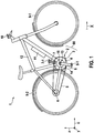
- FIG. 1 an electric bicycle as a preferred embodiment of the vehicle 1 according to the invention described in detail by way of example.
- the vehicle 1 comprises as electric bicycle a frame 12, to which a front wheel 9-1, a rear wheel 9-2 and a crank mechanism 2 with two cranks 7, 8 with Pedals 7-1 and 8-1 are arranged.
- An electric drive 3 is integrated in the crank mechanism 2.
- a pinion 6 is arranged at the rear wheel 9-2.
- a drive torque which is provided by the driver and / or by the electric drive 3, is transmitted to the pinion 6 via a chain 5 by a chainring 4 on the crank drive 2.
- a control unit 10 is further arranged, which is connected to the optionally formed electric drive 3.
- a battery 11 is further formed, which serves for the power supply of the electric drive 3.
- crank bearing 13 Integrated in the frame 12 is a crank bearing 13 or bottom bracket, which has a crankcase 14 and a crankshaft 15.
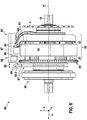
- the drive arrangement 80 according to the invention of the vehicle 1 according to the invention FIG. 1 has the crank mechanism 2 and the electric drive 3, wherein the torque generated by these via a corresponding and in FIG. 1 not shown transmission device 20 with a switchable multi-stage planetary gear 21 are receivable and transferable to the chainring as the output element 4.
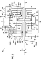
- FIG. 2 is a schematic plan view of an embodiment of the drive assembly 80 according to the invention with an electric drive 3 and a crank mechanism. 2
- a transmission device 20 is formed which has a planetary gear 21 arranged coaxially with the axis of rotation Y defined by the crankshaft 15.
- the planetary gear 21 consists of a Hochtreibergame 40 with a planetary gear 41 of the Hochtreibergame 40 on the one hand and a multi-stage gearbox 50 with a first and here two-stage planetary gear 51, namely the input side, the Hochtreiberease 40 facing away from the output element 4, and a second and here two-stage Planetary gear 52, namely the output side, facing the output element 4 and the high-drive stage 40 facing away.
- the first and second planetary gear 51 and 52 of the gearbox 50 have corresponding first and second sun gears 55 and 56 and the sun gears 55, 56 associated planet gears 57 and 58, which are mounted on planetary webs 22, 23 and coupled via a common ring gear 53 ,
- connection of the sun gears 55, 56 is effected with the housing 14 of the drive assembly 80 in a controlled manner.
- This is done in the embodiment according to FIG. 2 via the controlled switchable locking or releasing the rotatably connected to the sun gears 55, 56 and rotating cam followers 64 at the distal ends 63-2 of the shift finger 61 with the stop elements 68 on the link body 67 of the shift gate 66, in connection with the adjustment 60, the can also be referred to as actuator 60, spaced from the axis of rotation Y but axially parallel to this in the direction of arrow 95 is displaced.
- Each of the sun gears 55 of the first planetary gear 51 and each of the sun gears 56 of the second planetary gear 52 of the gear shift stages 50 has its own and connected to the respective sun gear 55, 56 rotatably coupled shift finger 61.
- the driver elements 64 which may also be referred to as claws or entrainment claws and located at the respective distal end 63-2 of the shift fingers 61, are in relation to the gaps 69 and the stop elements 68, which may also be referred to as abutment elements or link claws, arranged so coordinated that by moving the shift gate 66 along the direction of arrow 95, a separate or combined releasing or locking the individual sun gears 55 and 56 of the first and second planetary gear 51, 52 of the gear shift stages 50 of the gearbox can be achieved.
- a freewheel 59 or 59-1 is formed at different points of the gearbox 50, wherein the freewheel 59-1 is in connection with a direct gear.
- the Hochtreibergame 40 with the planetary gear 41 for introducing the torque generated by muscle power has a ring gear 42, an inner sun gear 43 and an intermediate planetary land 45 with planet 44 of the Hochtreiberlace 40.
- the motor torque generated by the electric drive 3 is delivered by the motor shaft 31 to the Motorreduziergetriebe 30 and ultimately transmitted to a spur gear 35 as the output element of the Motorreduziergetriebes 30, which is materially connected to the input side planetary ridge 22 of the gearbox 50th
- the motor reducer 30 consists of an arrangement of a plurality of spur gears 32 to 34, which transmit the engine torque on the output side to the spur gear 35 coupled to the input side planetary ridge 22.
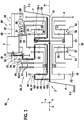
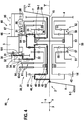
- FIG. 3 and 4 show once again the embodiment of the drive assembly 80 according to the invention from the FIG. 2 However, with the force, torque and power flows 101, 102 with respect to the driver and the engine power in a first gear or in the second to seventh gear of the arrangement FIG. 1 ,
- the power flows of the engine are designated by the reference numeral 101 and the power flows of the driver by the reference numeral 102.
- FIG. 5 shows another embodiment of the drive assembly 80 according to the invention, in which the connection of the motor 3 with the reducer 30 axially to the left and thus outside the arrangement of the shift finger 61 for both planetary gears 51, 52 is shifted.
- FIG. 6 shows a side view of another embodiment of the drive assembly 80 according to the invention, with a viewing direction perpendicular to the y-direction.
- FIGS. 7A to 7C show in a perspective side view or in lateral plan views used in one embodiment of the drive assembly 80 according to the invention switching gate 66 with link body 67 and sequences formed thereon of stop elements 68 provided therebetween gaps 69.
- This sequence of gaps 69 and stop elements 68 allows the controlled and thus single or combined locking or releasing the sun gears 55, 56 of the first and second planetary gear 51, 52 via appropriately trained and rotationally fixed with the sun gears 55, 56 of the planetary gear 51, 52 coupled shift finger 61 with the driver elements 64 at the distal ends 63-2.
- FIG. 8 shows a perspective side view of a shift finger 61, as it can be used in connection with the adjustment unit 60 of an embodiment of the drive assembly 80 according to the invention.
- the shift finger 61 is made according to FIG. 8 from an annular base 62, from which springs radially a radial portion 63 of a certain length. This means that the radial section 63 is attached to the base 62 with its proximal end 63-1. Opposite the proximal end 63-1, the distal end 63-2 is arranged, which forms a driver element 64.
- the area between the proximal end 63-1 and the distal end 63-2 is according to the embodiment FIG. 8 is formed by an elastic portion 65, which allows a resilient movement of the shift finger 61 in tangential or circumferential direction upon entering or releasing a stop of the shift finger 61. This allows a low-jerk or jerk-free coupling and decoupling of a sun gear 55, 56 during the gear change.
- FIG. 9 shows in a side view another embodiment of the drive assembly 80 according to the invention with focus on the actuator 60, which can also be referred to as an adjustment and the movement of the Schalkulisse 66 is used.
- gearbox 50 with the gear shift stages which are realized by a first planetary gear 51 and a second planetary gear 52 with a common ring gear 53.
- the high-drive stage 40 is formed on the input side.
- the output element 4 is in the form of a chainring.
- the gear 35 of the spur gear of the motor reducer 30 is shown for inputting the motor torque.
- the shift gate 66 of the adjusting unit 60 has on the side facing the gearbox 50 a sequence of stop elements 68 on the link body 67 with gaps 69 provided therebetween.
- the stopper elements 68 and the gaps 69 are formed and arranged such that by moving the link body 67 along the displacement direction 95, here parallel to the axis of rotation Y of the crankshaft 15, controlled and optionally the driver elements 64 of the sun gears of the first and second planetary gear 51, 52nd can be selectively released or detected individually or in combination with each other in their rotation with the sun gears 55, 56.
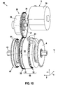
- FIG. 10 shows a side view of another embodiment of the drive assembly 80 according to the invention with a focus on the electric drive 3 and the motor reducer 30th
- No spur gear is provided for transmitting the torque of the motor shaft 31 to the gear 35 of the spur gear, but an evoloid gear with a Evoloidritzel 36 which is attached to the motor shaft 31.
- the Evoloidritzel meshes with an Evoloid leopardrad 37.
- Outside of the ring gear 38 is a toothing, which meshes with the output-side gear 35 of the spur gear of the engine reduction gear 30 and provides the torque to the output side.
- the motor 3 is located in the core inside a motor housing 39th
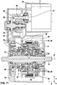
- FIG. 11 shows a sectional view of another embodiment of the drive assembly 80 according to the invention.
- the Motorreduziergetriebe 30 also consists of a Evoloid leopardrad 37 with an Evoloidritzel 36 on the motor shaft 31, which meshes with the Evoloid leopardrad 37.
- the electric drive 3 is housed with its essential components of the motor reducer 30 in a housing 39, which in turn is mounted on the bottom bracket 14 or forms part of it.
- FIG. 11 still has the peculiarity of a freewheel 75 and freewheels 76, the schematic also already in FIG. 2 are shown and themselves have no integrated storage. Furthermore, the bearings 77 and other bearings of the drive assembly 80 are still shown and the connections 54 between the shift fingers 61 and the corresponding sun gears 55, 56th
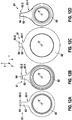
- FIG. 12 shows in side view various embodiments of the shift finger 61, which can be used in an embodiment of the drive assembly 80 according to the invention, for example, as the four shift fingers from the FIGS. 6 . 9 and 10 ,
- the different embodiments relate to the shape of the respective bases 62 and the length and thickness of the subsequent thereto with their proximal ends 63-1 radial sections 63 and also to the configuration of the driver elements 64 at the distal ends 63-2 of the radial sections 63.
- the Embodiments are each adapted so that an overlapping of the shift finger 61, for example by claw-like configuration in the y-direction of the transition from the radial portion 63 to the respective driver element 64 at the distal end 63-2 can be done without mutual collision and to achieve a particularly compact in the axial direction construction / design of the drive unit, the shift gate 66, for example, otherwise depending would extend laterally far beyond the chainring 4 after selected gear.
- An object of the invention is to provide a bicycle circuit, e.g. according to the basic principle of a hub gear and these in a drive assembly 80 on the bottom bracket 13, for. a pedelec or the like to integrate.
- a conventional switching device on the rear wheel 9-2 can then be omitted according to the invention.
- a particularly compact configuration of a drive assembly 80 is to be achieved with high efficiency, which is power shift capable, allows switching without interruption of traction and manages without or with a reduced amount of empty paths.
- Tretlagerantriebe with integrated gearbox which have a hollow shaft motor coaxial with the pedal crankshaft and an axis-parallel to the pedal crankshaft gearbox are known.
- a friction ring gear as a continuously variable bicycle transmission in a pedelec / eBike bottom bracket drive is known.
- a friction ring transmission has the disadvantage of a lower efficiency than frictional transmission, which affects the battery range and drivability without engine assistance, especially when driving at over 25 km / h in pedelecs.
- bottom bracket drives with integrated circuits based on spur gears. These have the disadvantage of a comparatively lower torque density. Also, they are especially when downshifting in a lower gear not under load or only switchable under partial load. Furthermore, these circuits have no electromechanically actuated automatic gear selection.
- the switching takes place by holding or releasing gears by means of pawls, which are arranged around the central shaft of the gears and engage radially from the inside into the wheel body in a form-fitting manner.
- the invention has e.g. also the task of creating a power shiftable, traction-free and efficient automatic bicycle circuit and to integrate in a drive unit 80 on the bottom bracket 13 of a pedelec.
- a switching device on the rear wheel 9-2 can be omitted. In this case, a particularly compact representation of the pedelec drive is to be achieved.
- the invention solves this problem, inter alia, with the use and integration of a switchable planetary gear 21 in coaxial arrangement with the pedal crankshaft 15 and chainring 4.
- the switchable planetary gear 21 takes on the task of cycling or the variable ratio for the driving force of the driver.
- Varying the transmission or shifting takes place by blocking or releasing of sun gears 55, 56 of a gearbox 50 of planetary gear 21.
- the use of a positive gear improves the efficiency compared to an integrated friction gear.
- each shift finger 61 are mounted laterally, which are rotatably connected to the sun gears 55, 56 and rotate with them.
- the structure of the shift finger 61 is made elastic, e.g. by an elastic region 65 on or in the radial section 63. In this case, the shift finger 61 bears the maximum occurring braking torque on the sun gear 55, 56 without plastic material deformation.
- One or more shift fingers 61 may be connected via a mechanically self-switching freewheel with the sun gear 55, 56. This makes it possible to avoid a free travel of the cranks 7, 8 without power transmission in all switching operations.
- the shift finger 61 With the shift fingers 61, by means of the shift gate 66 in combination with the freewheel upon a change in the direction of rotation of the associated sun gears 55, 56, the shift finger 61 can be prevented from turning away from the shift gate 66 so that, when the sun gears 55, 56 are blocked, no free travel of the pedal cranksets 7, 8 without power transmission by the orbital period of the shift finger 61 to the position of the shift gate arises.
- the shifting of the shift gate 66 for the blockage of the shift finger 61 can be done automatically by an electric motor 90 with gear 91, 92 as an actuator.
- the rotational position of the shift finger 61 is detected by means of a sensor and thus the timing of the displacement of the shift gate 66 is controlled. This ensures that the shift gate 66 is completely in the correct position when the shift finger 61 reaches the position of the shift gate 66. It is thus misalignments and edge loads avoided.
- a particularly compact representation with high efficiency and a high number of switching stages or switchable gears is the realization of the switchable planetary gear 50 as a double step planetary gear with planetary gears 51 and 52 with connection of the two stepped planetary gear 51, 52 via a common ring gear 53 and a switchable planetary gear 50 upstream Hochtreibereck 40, which reduces the high torque of the driver reached.
- the stepped planetary gear 55 facing the input torque of the driver translates into the fast and the second stepped planetary gear 56 facing the chainring 4 decelerates.
- the additional ratio 1: 1 realized in this stepped planetary gear 55 can be connected to each other by a self-switching freewheel and thus in a simple way, the additional ratio 1: 1 realized in this stepped planetary gear 55.
- Another gear results in a compact manner by the connection of the pedal crankshaft 15 with the planetary ridge 23 of the slow-stepping stepped planetary gear 56 via a freewheel 59-1.
- shift gear 50 can optionally be a motor 3 via a reduction gear 30 preferably connected between Hochtreiberlace 40 and planetary gear 50.
- FIG. 1 shows in a preferred embodiment schematically the construction of a pedelec / eBike bottom bracket drive 80 with an integrated power shiftable planetary gear 50 in coaxial arrangement with the crankshaft 15 and chainring. 4
- the switchable planetary gear 50 is composed of two stepped planetary gears 51, 52, each with a stepped planetary 57, 58, which consists of two rotatably connected planets with different diameters together. Both stepped planetary gears 51, 52 are connected to each other via a common ring gear 53.
- the stepped planetary gear 56 facing the chainring 4 translates into the low-speed and the stepped planetary gear 55 facing the high-drive stage 40 on the left, in addition to the stepped planetary gear 56, translates into the fast.
- the two realized by freewheeling gear ratios do not have to be actively switched, but done by the two overrunning clutches each mechanically self-switching.
- the following table lists the seven realized gears of the preferred embodiment.
- the translations range from Translation 1 in first gear, the direct gear, to translation 0.25 in seventh gear. This results in a total spread of 400% and gear jumps of about 26% on average. This covers a required deployment from 2 m to 8 m for standard wheels.
- gearbox stages 50 are preferably designed so that the gear jumps are constant and, for example, not greater than 25% to 27%, as listed in the table below.
- FIG. 2 shows that two of the four shift fingers 61 are each connected via a self-switching overrunning clutch 59 with the associated sun gear 55, 56.
- the shift finger 61 can be held by means of the shift gate 66 in the blocking position and at the same time the sun gear 55, 56 released for a gear change again. This is done by the sun gear 55, 56 undergoes a reversal of direction during a gear change while the freewheel 59, the shift finger 61 from the associated sun gear 55, 56 decoupled.
- a shift gate 66 for the active variation of the translation or shifting the gears.
- the shift gate 66 is displaceable parallel to the direction of the crankshaft axis Y, namely in double arrow 95. By shifting the shift gate 66, the shift finger 61 and thus the sun gears 55, 56 are blocked individually or combined in both directions by the claws 68 of the shift gate 66.
- the shift gate 66 is designed so that the gears always in their order successively in both directions, i. up and down, without skipping gears.
- the position, distances and dimensions of the jaws 68 are selected so that according to the switching logic or according to the transmission scheme and the required switching speed, the shift finger 61 currently involved in a particular translation can be blocked or released.
- the edges of the claws are rounded to minimize edge beams.
- the shift fingers 61 may be provided with an elastic structure 65. This serves to reduce a switching shock in the blockage of the shift finger 61 and the sun gear 55, 56.
- the shift finger 61 and the elastic structure 65 endure the maximum occurring braking torque on the sun gear 55, 56 without plastic material deformation.
- FIG. 9 shows in a preferred embodiment, a device for an automated shifting of the shift gate 66 by an electric motor 90 with gear 91, 92 in the manner of an actuator 60.
- the transmission consists of a planetary gear 91 for the reduction of the engine speed, a spur gear 92 for the transition to a Intermediate shaft and a spindle 93 which is mounted on the intermediate shaft.
- the spindle nut 94 is positively connected to the shift gate 66, which is axially slidably mounted on the housing 14, connected.
- the rotational position of the shift finger 61 is detected when it revolves by means of a sensor in order to control the timing of the shifting of the shift gate. This ensures that the shift gate is completely in the correct blockage position for the selected gear when the corresponding shift finger 61 reaches the position of the shift gate 66.
- the planet carrier 45 of the Hochtreibergame 40 is the drive or input element of the Hochtreibergame 40 and rotatably connected directly to the pedal crankshaft 15.
- the output element of the high-drive stage 40 is the sun gear 43, which is connected to the planet carrier 22 of the left-hand stepped planetary gear 51 with speed-up conversion.
- the ring gear 42 of the high-drive stage is fixedly connected to the housing 14.
- FIGS. 6 and 10 show in a preferred embodiment, the connection of a motor 3 to support the driver power to the transmission 50th
- the Figures 3 and 4 show the different power flow 101, 102 of driver and engine power in first gear and in second to seventh gear.
- the motor reducer 30 is composed of a two-stage spur gear, wherein the motor-near gear stage is designed as a particularly compact Evoloidgetriebe with a pinion 36 on the motor shaft 31 with five teeth.
- the freewheel 75 is an overrunning clutch and is for decoupling the engine 3 in a case where the driver "overhauls" the engine, i. For example, in case of failure of the engine or at speeds over 25 km / h.
- FIG. 5 an alternative arrangement of the motor 3 is shown to the planetary ridge 22 of the left-side stepped planetary gear with translation in quick with two-stage spur gear as reducer 30.
- the Motorreduziergetriebe 30 uses the translation of the Hochtreiberform 40 and thus can be designed compact by the reduced by the translation of the Hochtreibercase 40 reduction of the Motorreduziergetriebes 30.
- FIG. 11 A sectional view of the construction of the pedelec / eBike bottom bracket drive 80 with manual transmission 50 and motor 3 with motor reducer 30 in a preferred embodiment shows FIG. 11 ,
- the bottom bracket drive 80 results from axially offset shaft connections of the planetary web 45 and the sun gear 43 of the high-drive stage 40.
- the electric drive 3 has a hollow shaft motor with an output-side hollow shaft.
- the hollow shaft motor can be arranged and formed coaxially with the axis of rotation Y of the crankshaft 15, the planetary gear 21, the input side planetary ridge 22 of the planetary gear 21 and / or the sun gear 43 of a possibly provided Hochtreiberlace 40.
- the hollow shaft of the hollow shaft motor of the electric drive 3 indirectly, for example via a Motorreduziergetriebe 30, or directly coupled to the input side planetary ridge 22 of the planetary gear 21 and / or with the sun gear 43 of a possibly provided Hochtreiberease 40 or be coupled, in particular in a controllable manner ,
- hollow shaft motor Preferably hollow shaft motor, engine electronics, planetary gear 21, 50, pedal crankshaft 15 and chainring 4 are arranged coaxially.
- the power shiftable planetary gear 20 is constructed according to the principle described above and has the corresponding advantages, taking on the task of a bicycle or a variable ratio for the driving force of the driver.
- each side shift finger 61 attached to the Sun gears 55, 56 are rotatably connected and rotate with them.
- a shift gate 66 which is arranged axially parallel to the pedal crankshaft 15 and axially displaceable in the direction of the crankshaft axis Y, for example with an electric motor, the shift fingers 61 and thus the sun gears 55, 56 are blocked individually or in combination in both directions of rotation.
- the rotor of a hollow shaft motor 3 is connected either directly or preferably via a motor reducer 30 to a rotating input element 22 of the planetary gear 21, 50.
- the stator is connected to the housing 14 together with the electronics.
- a hollow shaft motor between a Hochtreibergame 40, which is upstream of the planetary gearbox 21, 50 for reducing the driver torque, and the planetary gear 21, 50 are arranged.
- the Motorreduziergetriebe 30 uses the translation of the Hochtreiberease 40 and can be designed correspondingly compact.
- the engine 3 can be made more compact.
- the hollow shaft motor 3 also assumes the function of the actuator 60 and the actuator for the switching mechanism of the planetary gear 21, 50th This is done by the connection of the hollow shaft motor 3 via a shiftable transmission and spindle drive with the switching mechanism, in particular with a Shift gate 66.
- a pedelec / eBike bottom bracket drive with power shiftable planetary gear 21, 50 is formed in the other embodiments of the motor drive 3, a hollow shaft motor.
- the hollow shaft motor is coaxial with the pedal crankshaft 15 and the chainring 4 between the shift fingers 61 and the stepped planetary gear 51, 52 of the planetary gear 21, 50 are arranged.
- the rotor of the hollow shaft motor can be connected with its hollow shaft directly to the planetary ridge 22 of the stepped planetary gear 51, 52 of the planetary gear 21, 50.
- the stator and the motor electronics of the hollow shaft motor may be connected to the housing 14.
- the connections of the shift fingers 61 with the associated sun gears 55, 56 can pass inside the hollow shaft of the hollow shaft motor and through the hollow shaft.
- a shift finger freewheel 59 and another freewheel which can connect the planetary web 22, 23 with a sun gear 55, 56, may be disposed within the hollow shaft of the hollow shaft motor.
- the rotor of a hollow shaft motor via a planetary gear, in particular a stepped planetary gear, as a motor reducer to the planetary land 22 of the planetary gear 21, 50 be connected.
- a freewheel between the hollow shaft of the hollow shaft motor and the sun gear of the engine reducer can decouple the engine from the driveline at standstill of the engine to avoid an unfavorable for the driver efficiency by towing the engine.
- the planetary gear of the motor at the same center distance, the shafts of the planetary 57, 58 of the planetary gear 21, 50 share.
- this arrangement of a hollow shaft motor with motor reducer between Hochtreiberlace and an outer of the shift finger 61 is formed.
- a motor freewheel for decoupling the motor at engine standstill may be arranged between the planetary ridge as the output element of the motor reducer and the planetary ridge 22, 23 as a drive element of the planetary gear 21, 50.
- An alternative connection of a hollow shaft motor can take place via a two-stage spur gear as a motor reducer to the planetary ridge 22 of the planetary gear 21, 50.
- connection of the hollow shaft motor via a shiftable transmission and spindle drive can be done with a shift gate 66.
- the hollow shaft motor additionally assumes the function of an actuator 60 for the automatic switching mechanism of the planetary gear 21, 50, in particular for the automatic adjustment of the shift gate 66th
Abstract
Die vorliegende Erfindung betrifft eine Antriebsanordnung (80) eines mit Muskelkraft antreibbaren Fahrzeuges (1) und/oder - insbesondere zusätzlich - mit Motorkraft antreibbaren Fahrzeuges (1), eines Elektrofahrrades, eBikes, Pedelecs oder dergleichen, mit einer um eine Drehachse (Y) drehbaren Kurbelwelle (15) zum Aufnehmen eines ersten und insbesondere mit Muskelkraft erzeugten Drehmomentes und mit einer Übertragungseinrichtung (20), welche zum Übertragen des ersten Drehmomentes von der Kurbelwelle (15) an ein mit einem Antriebsrad (9-2) des Fahrzeuges (1) koppelbares Abtriebselement (4) und mittels eines - insbesondere automatisch - schaltbaren mehrstufigen Planetengetriebes (21) zu einer variablen Übersetzung ausgebildet ist, bei welcher die Übersetzung des Planetengetriebes (21) über einen Gangwechsel und durch gesteuertes Verbinden und/oder Freigeben jeweiliger Sonnenräder (55, 56) entsprechender Planetenstufen (57, 58) über ein mit dem jeweiligen Sonnenrad (55, 56) drehfest gekoppeltes Mitnehmerelement (64) einstellbar ist und das jeweilige Mitnehmerelement (64) radial und/oder axial außerhalb des jeweils gekoppelten Sonnenrades (55, 56) angeordnet ist.The present invention relates to a drive arrangement (80) of a vehicle (1) driven by muscular force and / or - in particular additionally - driven by motor power vehicle (1), an electric bicycle, eBikes, pedelecs or the like, with a about an axis of rotation (Y) rotatable Crankshaft (15) for receiving a first and in particular generated by muscle torque and with a transmission device (20) which for transmitting the first torque from the crankshaft (15) to a drive wheel (9-2) of the vehicle (1) coupled Output element (4) and by means of a - in particular automatically - switchable multi-stage planetary gear (21) is formed to a variable ratio, in which the translation of the planetary gear (21) via a gear change and controlled connection and / or release of respective sun gears (55, 56 ) corresponding planetary stages (57, 58) via a with the respective sun gear (55, 56) drehfe st coupled driver element (64) is adjustable and the respective driver element (64) radially and / or axially outside of the respective coupled sun gear (55, 56) is arranged.
Description
Die vorliegende Erfindung betrifft eine Antriebsanordnung und ein Fahrzeug. Die vorliegende Erfindung betrifft insbesondere eine Antriebsanordnung eines mit Muskelkraft und/oder- gegebenenfalls zusätzlich - mit Motorkraft antreibbaren Fahrzeuges, eines Elektrofahrrades, eBikes, Pedelecs oder dergleichen sowie ein mit Muskelkraft und/oder - gegebenenfalls zusätzlich - mit Motorkraft antreibbares Fahrzeug, ein Elektrofahrrad, eBike, Pedelec oder dergleichen.The present invention relates to a drive assembly and a vehicle. The present invention relates in particular to a drive arrangement of a vehicle with muscle power and / or optionally additionally - driven by engine power, an electric bicycle, eBikes, pedelecs or the like and with muscle power and / or - optionally additionally - driven by engine power vehicle, an electric bicycle, eBike , Pedelec or the like.
Oft werden Fahrräder, Elektrofahrräder und dergleichen am angetriebenen Hinterrad mit einer Ketten- oder Nabenschaltung ausgebildet. Alternativ dazu können auch Tretlagerantriebe mit einem integrierten Schaltgetriebe vorgesehen werden.Often bicycles, electric bicycles and the like are formed on the driven rear wheel with a chain or hub circuit. Alternatively, bottom bracket drives with an integrated gearbox can be provided.
Problematisch ist bei bekannten Antriebsanordnungen mit am Tretlager angeordneten Schaltgetrieben deren gesteigerte Größe und/oder ihr mangelnder Wirkungsgrad. Dies betrifft insbesondere am Tretlagerantrieb ausgebildete Reibringgetriebe, Schaltgetriebe mit Hohlwellenmotor oder dergleichen. Auch ist ein Mangel an Lastschaltfähigkeit, Zugkraftunterbrechungsfreiheit und das Auftreten von Leerwegen bei bekannten Antriebsanordnungen nachteilig.The problem with known drive arrangements arranged on the bottom bracket gearboxes whose increased size and / or their lack of efficiency. This relates in particular to the bottom bracket drive trained friction ring gearbox, manual transmission with hollow shaft motor or the like. Also, a lack of power shift capability, traction interruption freedom and the occurrence of idle paths in known drive arrangements is disadvantageous.
Die erfindungsgemäße Antriebsanordnung mit den Merkmalen des Anspruchs 1 weist demgegenüber den Vorteil auf, dass bei vergleichsweise kleinem Bauraum im Bereich des Tretlagers die Drehmomentübertragung mit einem vergleichsweise hohen Wirkungsgrad, das heißt bei reduzierten Verlusten, und darüber hinaus auch unter Last und somit ohne Unterbrechung der Zugkraft bei besonders geringen oder gar verschwindenden Leerwegen erfolgen kann. Dies wird erfindungsgemäß mit den Merkmalen des unabhängigen Anspruches 1 dadurch erreicht, dass eine Antriebsanordnung geschaffen wird für ein mit Muskelkraft und/oder - insbesondere zusätzlich - mit Motorkraft antreibbares Fahrzeug, insbesondere für ein Elektrofahrrad, eBike, Pedelec oder dergleichen, mit einer um eine Drehachse drehbaren Kurbelwelle zum Aufnehmen eines ersten und insbesondere mit Muskelkraft erzeugten Drehmomentes und mit einer Übertragungseinrichtung, welche zum Übertragen des ersten Drehmomentes von der Kurbelwelle an ein mit einem Antriebsrad des Fahrzeuges koppelbares Abtriebselement und mittels eines - insbesondere automatisch - schaltbaren mehrstufigen Planetengetriebes zu einer variablen Übersetzung ausgebildet ist. Erfindungsgemäß ist die Übersetzung des Planetengetriebes über einen Gangwechsel und durch gesteuertes Verbinden und/oder Freigeben jeweiliger Sonnenräder entsprechender Planetenstufen über ein mit dem jeweiligen Sonnenrad drehfest gekoppeltes Mitnehmerelement einstellbar. Das jeweilige Mitnehmerelement ist erfindungsgemäß radial und/oder axial außerhalb zumindest des jeweils gekoppelten Sonnenrades angeordnet in Bezug auf die Drehachse des Sonnenrades. Die Verwendung eines Planetengetriebes als formschlüssiges Getriebe erzielt einen besonders hohen Wirkungsgrad beim Übertragen des Drehmoments in Abtriebsrichtung. Darüber hinaus ist durch das Vorsehen von mit den jeweiligen Sonnenrädern drehfest gekoppelten Mitnehmerelementen außerhalb des jeweils gekoppelten Sonnenrades ein besonders zuverlässiges Verbinden, Blockieren oder Sperren und/oder Freigeben oder Entsperren der jeweiligen Sonnenräder möglich, weil auf Grund der achsenfernen Anordnung der Mitnehmerelemente und auf Grund der dadurch bei gleichem Moment reduzierten Kräfte mit besonders geringen Ausfällen und Verschleißerscheinungen zu rechnen ist.The drive assembly according to the invention with the features of
Erfindungsgemäß kann das jeweilige Mitnehmerelement in Bezug auf die Drehachse des Sonnenrades auch radial innerhalb, aber axial außerhalb des Sonnenrades ausgebildet sein. Bei größeren Sonnenrädern können sich die Mitnehmerelemente innerhalb des Radius der Sonnenräder, aber seitlich davon beabstandet befinden und dennoch im Vergleich zu den üblichen Klinken oder Ziehkeilen achsfern mit den entsprechenden Vorteilen bezüglich der Kräfte angeordnet sein.According to the invention, the respective driver element with respect to the axis of rotation of the sun gear may also be formed radially inside, but axially outside of the sun gear. For larger sun gears, the driver elements may be located within the radius of the sun gears, but laterally spaced therefrom and yet be located off-axis with the corresponding advantages in terms of forces as compared to the usual pawls or pull keys.
Die Unteransprüche zeigen bevorzugte Weiterbildungen der Erfindung.The dependent claims show preferred developments of the invention.
Bei einer besonders zuverlässigen Weiterbildung der erfindungsgemäßen Antriebsanordnung ist das Mitnehmerelement jeweils an einem oder als ein radial außen liegender oder äußerster Abschnitt eines mit dem jeweiligen Sonnenrad drehfest gekoppelten Schaltfingers ausgebildet. Auf diese Weise kann die Struktur des Mitnehmerelements unabhängig von der Kopplung an das Sonnenrad in geeigneter Weise ausgestaltet werden, um einen Gangwechsel besonders zuverlässig auszuführen.In a particularly reliable development of the drive arrangement according to the invention, the driver element is in each case formed on one or as a radially outer or outermost portion of a rotatably coupled to the respective sun gear shift finger. In this way, the structure of the driver element can be designed independently of the coupling to the sun gear in a suitable manner to perform a gear change particularly reliable.
Strukturelle besonders einfache Verhältnisse, auch im Hinblick auf den Montagevorgang, stellen sich ein, wenn der jeweilige Schaltfinger mit einerinsbesondere ringförmigen - Basis zur drehfesten Kopplung mit dem jeweiligen Sonnenrad und einem sich von der Basis im Wesentlichen radial nach außen erstreckenden Radialabschnitt ausgebildet ist. Die insbesondere ringförmige Basis erlaubt eine besonders zuverlässige drehfeste Kopplung mit dem jeweiligen Sonnenrad, z.B. durch eine direkte Verbindung mit diesem. Durch die Ausgestaltung von Klauen zur Realisierung der Mitnehmerelemente, lassen sich unterschiedliche Formgebungen einbringen, (a) um eine gegenseitige Störung einer Mehrzahl von Mitnehmerelementen und einer entsprechenden Mehrzahl von Sonnenrädern zu verhindern und gleichwohl einen zuverlässigen Gangwechsel durch gesteuertes selektives und/oder kombiniertes Sperren und Freigeben zu ermöglichen und (b) um eine in axialer Richtung besonders kompakte Bauweise oder Auslegung der Antriebseinheit zu erzielen. Dadurch kann vermieden werden, dass eine vorgesehene Schaltkulisse je nach gewähltem Gang seitlich weit über ein Kettenblatt als Abtriebselement hinausragt.Structural particularly simple conditions, also with regard to the assembly process, arise when the respective shift finger with a particular annular - base for rotationally fixed coupling with the respective sun gear and a radially extending from the base radially outwardly extending radial portion is formed. The particular annular base allows a particularly reliable rotationally fixed coupling with the respective sun gear, e.g. through a direct connection with this. By configuring claws to realize the driver elements, different shapes can be introduced, (a) to prevent mutual interference of a plurality of driver elements and a corresponding plurality of sun gears, and yet reliable gear shifting through controlled selective and / or combined locking and releasing to allow and (b) to achieve a particularly compact in the axial direction or design of the drive unit. As a result, it can be avoided that an intended shift gate, depending on the selected gear, protrudes laterally far beyond a chainring as output element.
Für den Benutzer stellt sich in der Anwendung ein besonders gleichförmiger Betrieb ein, wenn gemäß einer anderen bevorzugten Weiterbildung der erfindungsgemäßen Antriebsanordnung ein Radialabschnitt eines jeweiligen Schaltfingers einen elastischen Abschnitt aufweist oder bildet, welcher in Bezug auf die Drehachse des jeweils zu Grunde liegenden Sonnenrades tangential oder in Umfangsrichtung elastisch deformierbar ist, um bei einem Anschlag oder einer Freigabe des jeweiligen Mitnehmerelements eine ruckarme oder -freie Bewegung des zu Grunde liegenden Sonnenrades zu bewirken.For the user, a particularly uniform operation arises in the application, according to another preferred embodiment of the drive assembly according to the invention, a radial portion of a respective shift finger has or forms an elastic portion which tangentially or in relation to the axis of rotation of each underlying sun gear Circumferential direction is elastically deformable to cause a stop or release of the respective driver element a jerk-free or-free movement of the underlying sun gear.
Zur Vermeidung von Leerwegen der Tretkurbeln ohne Leistungsübertragung vom Fahrer zu einem Abtriebselement bei allen Schaltvorgängen durch eine Umlaufzeit der Mitnehmerelemente ist es in vorteilhafterweise bei einer Weiterbildung vorgesehen, dass mehrere Mitnehmerelemente über einen mechanisch selbstschaltenden Freilauf mit einem jeweiligen Sonnenrad verbunden ist, insbesondere im Zusammenhang mit einem Drehrichtungswechsel der zugehörigen Sonnenräder bei einem Gangwechsel und/oder mit einem Festhalten der jeweiligen Mitnehmerelemente in beiden Drehrichtungen, insbesondere durch einen Stellantrieb, z.B. in Form einer Schaltkulisse.To avoid idling the cranks without power transmission from the driver to an output element in all switching operations by a rotation period of the driver elements, it is advantageously provided in a development that several driver elements is connected via a mechanically self-switching freewheel with a respective sun gear, especially in connection with a Direction of rotation of the associated sun gears during a gear change and / or with a detention of the respective driver elements in both directions of rotation, in particular by an actuator, eg in the form of a shift gate.
Einige Mitnehmerelemente bzw. Schaltfinger können also über einen mechanisch selbstschaltenden Freilauf mit einem zugehörigen Sonnenrad verbunden sein.Some driver elements or shift fingers can therefore be connected via a mechanically self-switching freewheel with an associated sun gear.
Des Weiteren ist bei einer vorteilhaften Weiterbildung eine koaxiale Anordnung des mehrstufigen Planetengetriebes zur Drehachse und somit zur Kurbelwelle besonders platzsparend und führt zu einer vergleichsweise kompakten Bauform.Furthermore, in an advantageous embodiment, a coaxial arrangement of the multi-stage planetary gear to the rotation axis and thus to the crankshaft is particularly space-saving and leads to a comparatively compact design.
Die kompakte Bauweise der erfindungsgemäßen Antriebsanordnung im Sinne eines Tretlagerschaltgetriebes kann alternativ oder zusätzlich gesteigert werden, indem das Planetengetriebe auch zu einem rotationssymmetrisch ausgebildeten Abtriebselement koaxial ausgebildet wird, so dass sich eine Anordnung ergibt, bei welcher das Abtriebselement als rotationssymmetrische Komponente koaxial zur Drehachse der Kurbelwelle und zum Planetengetriebe ausgebildet ist. Das Abtriebselement kann vorzugsweise als Kettenblatt oder Zahnriemenblatt, je nach Antriebsart, ausgebildet sein.The compact design of the drive assembly according to the invention in terms of a bottom bracket can be alternatively or additionally increased by the planetary gear is formed coaxially to a rotationally symmetrical output member, so that there is an arrangement in which the output element as a rotationally symmetrical component coaxial with the axis of rotation of the crankshaft and is formed to the planetary gear. The output element may preferably be formed as a chainring or timing belt, depending on the type of drive.
Eine weitere Fortbildung der erfindungsgemäßen Antriebsanordnung weist eine erweiterte Anzahl an Gängen und/oder an schaltbaren Übersetzungen auf, nämlich durch den Einsatz von einem oder von mehreren Freiläufen, insbesondere für die Realisierung einer Übersetzung von 1:1, in einem Stufenplanetengetriebe mit einer Übersetzung ins Schnelle und/oder in der Gesamtübersetzung durch einen Direktgang. Dabei kann es insbesondere vorgesehen sein, dass diese Übersetzungen nicht aktiv schaltbar, sondern mechanisch selbstschaltend ausgebildet sind.A further development of the drive assembly according to the invention has an extended number of gears and / or switchable translations, namely by the use of one or more freewheels, in particular for the realization of a ratio of 1: 1, in a stepped planetary gear with a translation at speed and / or in the overall translation by a direct gear. It may be provided in particular that these translations are not actively switchable, but are mechanically self-switching.
Eine besonders bequeme Handhabung ergibt sich für den Anwender dann, wenn gemäß einer bevorzugten Ausführungsform der erfindungsgemäßen Antriebsanordnung das Planetengetriebe eine Mehrzahl von Gängen definiert, insbesondere mit einer Anzahl von sieben Gängen, mit Gangsprüngen, die konstant sind, nicht mehr als im Mittel etwa 26 % betragen und/oder im Einzelfall im Bereich von etwa 25 % bis etwa 27 % liegen, eine Gesamtspreizung von etwa 400 % definieren und/oder im Zusammenhang stehen mit einem zusätzlichen Direktgang und dem Einsatz eines Freilaufes, durch welchen in einem Planetengetriebe mit einer Übersetzung ins Schnelle ein Sonnenrad mit einem Planetensteg verbindbar ist. Jedoch sind auch andere Ausgestaltungen denkbar.A particularly convenient handling results for the user if, according to a preferred embodiment of the drive arrangement according to the invention, the planetary gear defines a plurality of gears, in particular with a number of seven gears, with gearshifts that are constant, no more than about 26% on average be and / or in an individual case in the range of about 25% to about 27%, define a total spread of about 400% and / or are associated with an additional direct gear and the use of a freewheel through which in a planetary gear with a translation into Fast a sun gear is connectable to a planetary bridge. However, other embodiments are conceivable.
Verluste auf Grund von Reibung und dergleichen lassen sich in geeigneter Weise kontrollieren, indem das Planetengetriebe mit einer entsprechenden Zahl von Schaltgetriebeschaltstufen ausgebildet wird, beispielsweise mit höchstens vier Schaltgetriebeschaltstufen. Es sind jedoch auch andere Anzahlen von Schaltgetriebeschaltstufen realisierbar.Losses due to friction and the like can be suitably controlled by forming the planetary gear with a corresponding number of gear shift stages, for example, at most four gear shift stages. However, there are also other numbers of gear shift stages feasible.
Bei einer konkreten Ausgestaltungsform der erfindungsgemäßen Antriebsanordnung ist es vorgesehen, dass die Getriebeschaltstufen gebildet werden von (i) einem ersten und insbesondere zweistufigen Planetengetriebe mit Gesamtübersetzung ins Schnelle und (ii) einem dazu in Reihe geschalteten zweiten und insbesondere zweistufigen Planetengetriebe mit Gesamtübersetzung ins Langsame, insbesondere einem Planetengetriebe in der Form eines Stufenplanetengetriebes, d.h. mit Planetenrädern, welche mehrere Stufen aufweisen, die drehfest miteinander verbunden sind.In a specific embodiment of the drive arrangement according to the invention, it is provided that the gear shift stages are formed by (i) a first and in particular two-stage planetary gear with overall ratio to fast and (ii) connected to a second series and in particular two-stage planetary gear with overall ratio to the slow, in particular a planetary gear in the form of a stepped planetary gear, ie with planet wheels, which have several stages which are rotatably connected to each other.
Dabei kann den Getriebeschaltstufen insbesondere (iii) eine Hochtreiberstufe mit einem oder in Form eines Planetengetriebes mit Übersetzung ins Schnelle zur Reduktion eines hohen Fahrerdrehmomentes eingangsseitig vorgeschaltet sein.In this case, the transmission shift stages can be preceded on the input side in particular by (iii) a high-drive stage with one or in the form of a planetary gear with a gear ratio to reduce a high driver torque.
Alternativ oder zusätzlich können (iv) die beiden in Reihe geschalteten Planetengetriebe der Getriebeschaltstufen über ein gemeinsames Hohlrad miteinander gekoppelt sein.Alternatively or additionally, (iv) the two planetary gears of the gear shift stages connected in series can be coupled together via a common ring gear.
Bei einer anderen vorteilhaften Ausgestaltungsform der erfindungsgemäßen Antriebsanordnung wird ein besonders zuverlässiger Gangwechsel dadurch ermöglicht, dass dieser über einen Stellantrieb durchführbar ist, insbesondere mittels einer in Bezug auf die Drehachse der Kurbelwelle und/oder der Sonnenräder radial beabstandeten und gesteuert achsenparallel positionierbaren Schaltkulisse mit einer Mehrzahl von Anschlagselementen für die Mitnehmerelemente.In another advantageous embodiment of the drive assembly according to the invention a particularly reliable gear change is characterized makes it possible to carry it out via an actuator, in particular by means of a shift gate which is radially spaced relative to the axis of rotation of the crankshaft and / or the sun gears and can be controlled axially parallel with a plurality of stop elements for the driver elements.
Die vorliegende Erfindung lässt sich nicht nur bei rein mit Muskelkraft betriebenen Fahrzeugen, z.B. bei klassischen Fahrrädern, anwenden, sondern insbesondere bei Elektrofahrrädern, eBikes, Pedelecs oder dergleichen, wie dies eingangs bereits erwähnt wurde.The present invention can be applied not only to purely muscular powered vehicles, e.g. in classic bicycles, apply, but especially in electric bicycles, eBikes, pedelecs or the like, as already mentioned.
Bei einer bevorzugten Ausführungsform der erfindungsgemäßen Antriebsanordnung ist es daher vorgesehen, dass ein elektrischer Antrieb zum Erzeugen eines Motordrehmoments ausgebildet ist und dass der elektrische Antrieb zum Übertragen des Motordrehmomentes über das Planetengetriebe steuerbar an das Abtriebselement koppelbar ist.In a preferred embodiment of the drive arrangement according to the invention, it is therefore provided that an electric drive for generating a motor torque is formed and that the electric drive for transmitting the engine torque via the planetary gear is controllably coupled to the output element.
Bei einer besonders vorteilhaften Weiterbildung der erfindungsgemäßen Antriebsanordnung weist der elektrische Antrieb einen Hohlwellenmotor mit einer ausgangsseitigen Hohlwelle auf.In a particularly advantageous development of the drive arrangement according to the invention, the electric drive has a hollow shaft motor with an output-side hollow shaft.
Dabei kann der Hohlwellenmotor insgesamt oder zumindest mit seiner Hohlwelle koaxial zur Drehachse der Kurbelwelle, zum Planetengetriebe, zum eingangsseitigen Planetensteg des Planetengetriebes und/oder zu einem Sonnenrad einer etwaig vorgesehenen Hochtreiberstufe angeordnet und ausgebildet sein.In this case, the hollow shaft motor as a whole or at least with its hollow shaft coaxial with the axis of rotation of the crankshaft, the planetary gear, arranged on the input side planetary gear of the planetary gear and / or a sun gear of a possibly provided Hochtreiberstufe and trained.
Zusätzlich oder alternativ kann die Hohlwelle des Hohlwellenmotors mittelbar, zum Beispiel über ein Motorreduziergetriebe, oder unmittelbar mit dem eingangsseitigen Planetensteg des Planetengetriebes und/oder mit dem Sonnenrad einer etwaig vorgesehenen Hochtreiberstufe gekoppelt oder koppelbar sein, insbesondere in steuerbarer Weise.Additionally or alternatively, the hollow shaft of the hollow shaft motor indirectly, for example via a Motorreduziergetriebe, or directly coupled to the input-side planetary gear of the planetary gear and / or with the sun of a possibly provided Hochtreiberstufe or be coupled, in particular in a controllable manner.
Dabei können die Ankopplung des elektrischen Antriebes und somit die Übertragung des Motordrehmomentes von der Motorwelle auf das Planetengetriebe in verschiedener Art und Weise realisiert sein.In this case, the coupling of the electric drive and thus the transmission of the motor torque from the motor shaft to the planetary gear can be realized in various ways.
Bei einer bevorzugten Ausgestaltungsform der erfindungsgemäßen Antriebsanordnung ist es dazu vorgesehen, dass zwischen dem elektrischen Antrieb und dem Planetengetriebe ein Motorreduziergetriebe ausgebildet ist, zum Beispiel in Form eines mehrstufigen Stirnradgetriebes, eines Planetengetriebes oder eines Stufenplanetengetriebes, mit koaxialer Anordnung zur Hohlwelle des Hohlwellenmotors, zur Drehachse der Kurbelwelle, zum Planetengetriebe, zum eingangsseitigen Planetensteg des Planetengetriebes und/oder zum Sonnenrad einer etwaig vorgesehenen Hochtreiberstufe und/oder in im Hohlwellenmotor integrierter Form.In a preferred embodiment of the drive arrangement according to the invention, it is provided that between the electric drive and the planetary gear, a Motorreduziergetriebe is formed, for example in the form of a multi-stage spur gear, a planetary gear or a stepped planetary gear, with coaxial arrangement to the hollow shaft of the hollow shaft motor, to the axis of rotation Crankshaft, the planetary gear, the input-side planetary gear of the planetary gear and / or the sun gear of a possibly provided Hochtreiberstufe and / or integrated in the hollow shaft motor shape.
Ein radial besonders kompakter Aufbau ergibt sich, wenn gemäß einer alternativen Ausgestaltungsform der erfindungsgemäßen Antriebsanordnung zwischen dem elektrischen Antrieb und dem Planetengetriebe ein Motorreduziergetriebe in Form eines Evoloidgetriebes ausgebildet ist. Diese kann innen- oder außenverzahnt ausgebildet sein.A radially particularly compact design results when, according to an alternative embodiment of the drive arrangement according to the invention between the electric drive and the planetary gear, a motor reducer in the form of an evoloid gear is formed. This can be formed internally or externally toothed.
Unabhängig von der Art und Weise, wie das Motorreduziergetriebe konfiguriert ist, ist es von besonderem Vorteil, wenn ein, mehrere oder sämtliche Komponenten des jeweiligen Motorreduziergetriebes mit oder aus einem Kunststoffmaterial gefertigt sind. Damit lassen sich die Betriebsgeräusche und/oder deren Übertragung bei der erfindungsgemäßen Antriebsanordnung weiter reduzieren.Regardless of the way in which the engine reducer is configured, it is particularly advantageous if one, several or all components of the respective engine reducer are made with or from a plastics material. Thus, the operating noise and / or their transmission in the drive assembly according to the invention can be further reduced.
Besonders bevorzugt ist eine Antriebsanordnung, welche den Aufbau eines Mittelmotorantriebs aufweist und insbesondere ein gemeinsames Gehäuse umfasst, in welchem das Planetengetriebe, der Stellantrieb, der elektrische Antrieb, das Motoreduziergetriebe und - zumindest teilweise - die Kurbelwelle aufgenommen sind.Particularly preferred is a drive arrangement, which has the structure of a mid-motor drive and in particular comprises a common housing in which the planetary gear, the actuator, the electric drive, the Motoreduziergetriebe and - at least partially - the crankshaft are added.
Die vorliegende Erfindung betrifft des Weiteren ein mit Muskelkraft und/oder - insbesondere zusätzlich - mit Motorkraft antreibbares Fahrzeug und insbesondere ein Elektrofahrrad, eBike, Pedelec oder dergleichen. Das erfindungsgemäße Fahrzeug weist mindestens ein Rad auf sowie eine erfindungsgemäß ausgebildete Antriebsanordnung, mit welcher das mindestens eine Rad des Fahrzeuges antreibbar ist.The present invention furthermore relates to a vehicle which can be driven by motor power and / or-in particular additionally-by motor power, and in particular an electric bicycle, eBike, pedelec or the like. The vehicle according to the invention has at least one wheel and a drive arrangement designed according to the invention with which the at least one wheel of the vehicle can be driven.
Unter Bezugnahme auf die beigefügten Figuren werden Ausführungsformen der Erfindung im Detail beschrieben.
Figur 1- ist eine schematische Darstellung eines Beispiels eines Fahrzeuges nach Art eines Elektrofahrrades, bei welchem eine erste Ausführungsform der Erfindung realisiert ist;
- Figur 2
- ist eine schematische Draufsicht auf eine Ausführungsform der erfindungsgemäßen Antriebsanordnung mit Kurbeltrieb und mit elektrischem Antrieb;
Figuren 3 und 4- zeigt die Ausführungsform der erfindungsgemäßen Antriebsanordnung gemäß
Figur 2 in zwei unterschiedlichen Betriebszuständen sowie die dabei auftretenden Kraft- und Drehmomentflüsse; Figur 5- ist eine schematische Draufsicht auf eine andere Ausführungsform der erfindungsgemäßen Antriebsanordnung mit Kurbeltrieb und mit einem elektrischen Antrieb mit alternativer Ankopplung;
- Figur 6
- zeigt eine seitliche Ansicht einer anderen Ausführungsform der erfindungsgemäßen Antriebsanordnung;
- Figur 7A bis 7C
- zeigen eine Schaltkulisse, die im Zusammenhang mit einer Ausführungsform der erfindungsgemäßen Antriebsanordnung zum Gangwechsel eingesetzt werden kann;
Figur 8- zeigt in perspektivischer Seitenansicht einen Schaltfinger, der bei einer Ausführungsform der erfindungsgemäßen Antriebsanordnung eingesetzt werden kann;
- Figur 9
- zeigt die Ausführungsform der erfindungsgemäßen Antriebsanordnung aus
Figur 6 mit Fokus auf die Antriebskomponenten für die Schaltkulisse; Figur 10- zeigt in perspektivischer Seitenansicht die Ausführungsform der erfindungsgemäßen Antriebsanordnung gemäß den
Figuren 6 und9 mit Fokus auf den elektrischen Antrieb; Figur 11- zeigt die Ausführungsform der erfindungsgemäßen Antriebsanordnung aus
Figur 10 in geschnittener Darstellung; - Figuren 12A bis 12D
- zeigen Seitenansichten verschiedener Schaltfinger, die bei einer Ausführungsform der erfindungsgemäßen Antriebsanordnung verwendet werden können.
- FIG. 1
- is a schematic representation of an example of a vehicle in the manner of an electric bicycle, in which a first embodiment of the invention is realized;
- FIG. 2
- is a schematic plan view of an embodiment of the drive assembly according to the invention with crank mechanism and with electric drive;
- FIGS. 3 and 4
- shows the embodiment of the drive assembly according to the invention according to
FIG. 2 in two different operating states as well as the occurring force and torque flows; - FIG. 5
- is a schematic plan view of another embodiment of the drive assembly according to the invention with crank mechanism and with an electric drive with alternative coupling;
- FIG. 6
- shows a side view of another embodiment of the drive assembly according to the invention;
- FIGS. 7A to 7C
- show a shift gate, which can be used in connection with an embodiment of the drive assembly according to the invention for gear change;
- FIG. 8
- shows a perspective side view of a shift finger, which can be used in one embodiment of the drive assembly according to the invention;
- FIG. 9
- shows the embodiment of the drive assembly according to the invention
FIG. 6 with a focus on the drive components for the shift gate; - FIG. 10
- shows a perspective side view of the embodiment of the drive arrangement according to the invention according to the
FIGS. 6 and9 with focus on the electric drive; - FIG. 11
- shows the embodiment of the drive assembly according to the invention
FIG. 10 in a sectional view; - FIGS. 12A to 12D
- show side views of various shift fingers that can be used in one embodiment of the drive assembly according to the invention.
Nachfolgend werden unter Bezugnahme auf die
Die dargestellten Merkmale und weitere Eigenschaften können in beliebiger Form voneinander isoliert und beliebig miteinander kombiniert werden, ohne den Kern der Erfindung zu verlassen.The illustrated features and other properties can be isolated in any form from each other and combined with each other, without departing from the gist of the invention.
Zunächst wird unter Bezugnahme auf
Das Fahrzeug 1 umfasst als Elektrofahrrad einen Rahmen 12, an dem ein Vorderrad 9-1, ein Hinterrad 9-2 und ein Kurbeltrieb 2 mit zwei Kurbeln 7, 8 mit Pedalen 7-1 und 8-1 angeordnet sind. Ein elektrischer Antrieb 3 ist in den Kurbeltrieb 2 integriert. Am Hinterrad 9-2 ist ein Ritzel 6 angeordnet.The
Ein Antriebsmoment, welches durch den Fahrer und/oder durch den elektrischen Antrieb 3 bereitgestellt wird, wird von einem Kettenblatt 4 am Kurbeltrieb 2 über eine Kette 5 auf das Ritzel 6 übertragen.A drive torque, which is provided by the driver and / or by the
Am Lenker des Fahrzeuges 1 ist ferner eine Steuereinheit 10 angeordnet, welche mit dem gegebenenfalls ausgebildeten elektrischen Antrieb 3 verbunden ist. Im oder am Rahmen 12 ist ferner eine Batterie 11 ausgebildet, welche zur Stromversorgung des elektrischen Antriebes 3 dient.On the handlebars of the
Im Rahmen 12 integriert ist ein Kurbellager 13 oder Tretlager, welches ein Kurbelgehäuse 14 und eine Kurbelwelle 15 aufweist.Integrated in the
Die erfindungsgemäße Antriebsanordnung 80 des erfindungsgemäßen Fahrzeuges 1 aus
Zur Übertragung von Drehmomenten vom Kurbeltrieb 2 und vom elektrischen Antrieb 3 ist eine Übertragungseinrichtung 20 ausgebildet, welche ein mit einem koaxial zu der durch die Kurbelwelle 15 definierten Drehachse Y angeordnetes Planetengetriebe 21 aufweist.To transmit torques from the crank mechanism 2 and the
Das Planetengetriebe 21 besteht aus einer Hochtreiberstufe 40 mit einem Planetengetriebe 41 der Hochtreiberstufe 40 einerseits und einem mehrstufigen Schaltgetriebe 50 mit einem ersten und hier zweistufigen Planetengetriebe 51, nämlich eingangsseitig, der Hochtreiberstufe 40 zugewandt und vom Abtriebselement 4 abgewandt, und einem zweiten und hier zweistufigen Planetengetriebe 52, nämlich ausgangsseitig, dem Abtriebselement 4 zugewandt und der Hochtreiberstufe 40 abgewandt.The planetary gear 21 consists of a
Die ersten und zweiten Planetengetriebe 51 und 52 des Schaltgetriebes 50 weisen entsprechende erste und zweite Sonnenräder 55 bzw. 56 und den Sonnenrädern 55, 56 zugeordnete Planetenräder 57 bzw. 58 auf, die an Planetenstegen 22, 23 gelagert und über ein gemeinsames Hohlrad 53 gekoppelt sind.The first and second
Über lösbare Verbindungen wird die Verbindung der Sonnenräder 55, 56 mit dem Gehäuse 14 der Antriebsordnung 80 in gesteuerter Art und Weise bewirkt. Dies geschieht bei der Ausführungsform gemäß
Jedes der Sonnenräder 55 des ersten Planetengetriebes 51 und jedes der Sonnenräder 56 des zweiten Planetengetriebes 52 der Getriebeschaltstufen 50 weist einen eigenen und mit dem jeweiligen Sonnenrad 55, 56 drehfest gekoppelten Schaltfinger 61 auf. Die Mitnehmerelemente 64, die auch als Klauen oder als Mitnehmerklauen bezeichnet werden können und sich am jeweiligen distalen Ende 63-2 der Schaltfinger 61 befinden, sind in Bezug auf die Lücken 69 und die Anschlagselemente 68, die auch als Widerlagerelemente oder Kulissenklauen bezeichnet werden können, so abgestimmt angeordnet, dass durch Verschieben der Schaltkulisse 66 entlang der Pfeilrichtung 95 ein getrenntes oder kombiniertes Freigeben oder Sperren der einzelnen Sonnenräder 55 und 56 der ersten und zweiten Planetengetriebe 51, 52 der Getriebeschaltstufen 50 des Schaltgetriebes erreicht werden kann.Each of the sun gears 55 of the first
Ferner ist an verschiedenen Stellen des Schaltgetriebes 50 jeweils ein Freilauf 59 bzw. 59-1 ausgebildet, wobei der Freilauf 59-1 im Zusammenhang mit einem Direktgang steht.Further, in each case a
Die Hochtreiberstufe 40 mit dem Planetengetriebe 41 zum Einbringen des mit Muskelkraft erzeugten Drehmomentes weist ein Hohlrad 42, ein innenlaufendes Sonnenrad 43 sowie einen dazwischen laufenden Planetensteg 45 mit Planeten 44 der Hochtreiberstufe 40 auf.The
Andererseits wird das vom elektrischen Antrieb 3 erzeugte Motordrehmoment durch die Motorwelle 31 an das Motorreduziergetriebe 30 abgegeben und letztlich an ein Stirnrad 35 als Abtriebselement des Motorreduziergetriebes 30 übertragen, welches materiell verbunden ist mit dem eingangsseitigen Planetensteg 22 des Schaltgetriebes 50.On the other hand, the motor torque generated by the
In dem in
Die
Die Leistungsflüsse des Motors sind jeweils mit dem Bezugszeichen 101 und die Leistungsflüsse des Fahrers mit dem Bezugszeichen 102 bezeichnet.The power flows of the engine are designated by the
Zu erkennen sind die mit der Kurbelwelle 15 im Zusammenhang stehende Drehachse Y, um welche koaxial angeordnet sind das Abtriebselement 4 in Form eines Kettenblatts, das Schaltgetriebe 50 mit den entsprechenden Getriebeschaltstufen und den ersten und zweiten Planetengetrieben 51 und 52 und die Hochtreiberstufe 40. Zu erkennen sind des Weiteren die drehfest mit den Sonnenrädern 55 und 56 verbundenen Schaltfinger 61 mit den Mitnehmerelementen 64 an deren distalen Enden 63-2. Die weitere Kopplung der ersten und zweiten Planetengetriebe 51 und 52 erfolgt über das gemeinsame Hohlrad 53. Das Einbringen eines Motordrehmoments erfolgt über das ebenfalls koaxial vorgesehene Stirnrad 35 als Abtriebselement des Motorreduziergetriebes 30.To recognize the associated with the
Die
Der Schaltfinger 61 besteht gemäß
Dargestellt ist wiederum das Schaltgetriebe 50 mit den Getriebeschaltstufen, die durch ein erstes Planetengetriebe 51 und ein zweites Planetengetriebe 52 mit einem gemeinsamen Hohlrad 53 realisiert werden. Eingangsseitig ist die Hochtreiberstufe 40 ausgebildet. Ausgangsseitig befindet sich das Abtriebselement 4 in Form eines Kettenblatts. Ferner ist das Zahnrad 35 der Stirnradstufe des Motorreduziergetriebes 30 zur Eingabe des Motordrehmoments dargestellt.Shown again is the
Die Hochtreiberstufe 40 mit dem entsprechenden Planetengetriebe 41, das Zahnrad 35 der Stirnradstufe des Motorreduziergetriebes 30, die Getriebeschaltstufen 50 mit dem ersten und zweiten Planetengetriebe 51 bzw. 52, die zum Ausführen des Schaltvorgangs notwendigen Schaltfinger 61 mit den Mitnehmerelementen 64 an deren distalen Enden 63-2 und das Abtriebselement 4 sind konzentrisch und koaxial in Bezug auf die Drehachse Y der zu Grunde liegenden Kurbelwelle 15 ausgebildet.The
Die Schaltkulisse 66 der Verstelleinheit 60 weist auf der dem Schaltgetriebe 50 zugewandten Seite eine Abfolge von Anschlagselementen 68 am Kulissenkörper 67 mit dazwischen vorgesehenen Lücken 69 auf. Die Anschlagselemente 68 und die Lücken 69 sind so ausgebildet und angeordnet, dass durch das Bewegen des Kulissenkörpers 67 entlang der Verschiebungsrichtung 95, hier parallel zur Rotationsachse Y der Kurbelwelle 15, gesteuert und wahlweise die Mitnehmerelemente 64 der Sonnenräder der ersten und zweiten Planetengetriebe 51, 52 selektiv einzeln oder kombiniert miteinander in ihrer Rotation mit den Sonnenrädern 55, 56 freigegeben oder festgestellt werden können.The
In der Ausführungsform gemäß
Durch Betätigung des Motors 90 des Antriebs für die Schaltkulisse 66 erfolgt über die Drehung der Spindel 93 und entsprechendes Mitführen der Spindelmutter 94 das Verschieben des Kulissenkörpers 67 in der Richtung des Verschiebungspfeils 95. Der Betrieb des Motors 90 und somit das Verschieben des Kulissenkörpers 67 können unter Auswertung von Signalen einer hier nicht dargestellten Sensorik in gesteuerter Art und Weise so erfolgen, dass eine Kollision bei der Bewegung der Anschlagselemente 68, die auch als Kulissenklauen bezeichnet werden, und der umlaufenden Schaltfinger 61 mit den Mitnehmerelementen 64 in y-Richtung vermieden wird.By operating the
Bei der Ausführungsform gemäß
Der Motor 3 befindet sich in dem Kern nach im Inneren eines Motorgehäuses 39.The
Bei dieser besteht das Motorreduziergetriebe 30 ebenfalls aus einem Evoloidzahnrad 37 mit einem Evoloidritzel 36 auf der Motorwelle 31, welches mit dem Evoloidzahnrad 37 kämmt.In this, the
Der elektrische Antrieb 3 ist mit seinen wesentlichen Komponenten des Motorreduziergetriebes 30 in einem Gehäuse 39 untergebracht, welches seinerseits am Tretlagergehäuse 14 montiert ist oder einen Teil davon bildet.The
Zusätzlich zu der in
Der elektrische Antrieb 3 bei der Ausführungsform der erfindungsgemäßen Antriebsanordnung 80 gemäß
Die unterschiedlichen Ausgestaltungen beziehen sich auf die Gestalt der jeweiligen Basen 62 und der Länge und Stärke der sich daran mit ihren proximalen Enden 63-1 anschließenden Radialabschnitte 63 und auch auf die Ausgestaltung der Mitnehmerelemente 64 an den distalen Enden 63-2 der Radialabschnitte 63. Die Ausgestaltungen sind jeweils so angepasst, dass ein Übergreifen der Schaltfinger 61 z.B. durch klauenartige Ausgestaltung in y-Richtung des Übergangs vom Radialabschnitt 63 zum jeweiligen Mitnehmerelement 64 am distalen Ende 63-2 ohne gegenseitige Kollision erfolgen kann und um eine in axialer Richtung besonders kompakte Bauweise/Auslegung der Antriebseinheit zu erzielen, wobei die Schaltkulisse 66 beispielsweise sonst je nach gewähltem Gang seitlich weit über das Kettenblatt 4 hinausragen würde.The different embodiments relate to the shape of the
Diese und weitere Merkmale und Eigenschaften der vorliegenden Erfindung werden an Hand der folgenden Darlegungen weiter erläutert:
- Die Erfindung betrifft insbesondere Elektrofahrräder, Pedelecs, eBikes und dergleichen, insbesondere mit Mittelmotorantrieb und einer Fahrradschaltung zur Anpassung der begrenzten Antriebskraft des Fahrers an die unterschiedlichen Fahrwiderstände.
- The invention relates in particular to electric bicycles, pedelecs, eBikes and the like, in particular with a central motor drive and a bicycle circuit for adapting the limited driving force of the driver to the different driving resistances.
Eine Zielsetzung der Erfindung ist die Schaffung einer Fahrradschaltung z.B. nach dem Grundprinzip einer Nabenschaltung und diese in eine Antriebsanordnung 80 am Tretlager 13 z.B. eines Pedelecs oder dergleichen zu integrieren.An object of the invention is to provide a bicycle circuit, e.g. according to the basic principle of a hub gear and these in a
Eine übliche Schaltvorrichtung am Hinterrad 9-2 kann dann erfindungsgemäß entfallen.A conventional switching device on the rear wheel 9-2 can then be omitted according to the invention.
Dabei soll eine besonders kompakte Konfiguration einer Antriebsanordnung 80 mit hohem Wirkungsgrad erzielt werden, die lastschaltfähig ist, ein Schalten ohne Zugkraftunterbrechung erlaubt und dabei ohne oder mit einem verringerten Maß an Leerwegen auskommt.In this case, a particularly compact configuration of a
Bekannt sind Tretlagerantriebe mit integriertem Schaltgetriebe, welche einen Hohlwellenmotor koaxial zur Tretkurbelwelle und ein zur Tretkurbelwelle achsparalleles Schaltgetriebe aufweisen.Tretlagerantriebe with integrated gearbox, which have a hollow shaft motor coaxial with the pedal crankshaft and an axis-parallel to the pedal crankshaft gearbox are known.
Ferner ist die Integration eines Reibringgetriebes als stufenlos verstellbares Fahrradschaltgetriebe in einen Pedelec/eBike-Tretlagerantrieb bekannt. Ein Reibringgetriebe hat als reibschlüssiges Getriebe den Nachteil eines im Vergleich geringeren Wirkungsgrads, welcher sich auf die Batteriereichweite und die Fahrbarkeit ohne Motorunterstützung, insbesondere beim Fahren mit über 25 km/h bei Pedelecs, auswirkt.Furthermore, the integration of a friction ring gear as a continuously variable bicycle transmission in a pedelec / eBike bottom bracket drive is known. A friction ring transmission has the disadvantage of a lower efficiency than frictional transmission, which affects the battery range and drivability without engine assistance, especially when driving at over 25 km / h in pedelecs.
Ein weiteres Konzept sind Tretlagerantriebe mit integrierten Schaltungen auf der Basis von Stirnradgetrieben. Diese haben den Nachteil einer vergleichsweise geringeren Drehmomentdichte. Auch sind sie insbesondere beim Herunterschalten in einen niedrigeren Gang nicht unter Last bzw. nur unter Teillast schaltbar. Des Weiteren weisen diese Schaltungen keine elektromechanisch aktuierte automatische Gangwahl auf.Another concept is bottom bracket drives with integrated circuits based on spur gears. These have the disadvantage of a comparatively lower torque density. Also, they are especially when downshifting in a lower gear not under load or only switchable under partial load. Furthermore, these circuits have no electromechanically actuated automatic gear selection.
Andere Konzepte haben den Nachteil, dass das Schalten nicht zugkraftunterbrechungsfrei erfolgt. Der Fahrer erfährt beim Schalten, insbesondere wenn er beschleunigt in die Pedale tritt, einen deutlich spürbaren Leerweg der Tretkurbeln.Other concepts have the disadvantage that the switching is not traction interruption-free. The driver experiences when switching, in particular when he accelerates pedaling, a clearly noticeable free travel of the cranks.
Bei anderen bekannten Mechanismen erfolgt das Schalten durch Festhalten oder Freigeben von Zahnrädern mittels Klinken, welche um die zentrale Welle der Zahnräder angeordnet sind und radial von innen in den Radkörper formschlüssig eingreifen.In other known mechanisms, the switching takes place by holding or releasing gears by means of pawls, which are arranged around the central shaft of the gears and engage radially from the inside into the wheel body in a form-fitting manner.
Die Erfindung hat z.B. auch die Aufgabe, eine lastschaltfähige, zugkraftunterbrechungsfreie und effiziente Automatikfahrradschaltung zu schaffen und in eine Antriebseinheit 80 am Tretlager 13 eines Pedelecs zu integrieren.The invention has e.g. also the task of creating a power shiftable, traction-free and efficient automatic bicycle circuit and to integrate in a
Eine Schaltvorrichtung am Hinterrad 9-2 kann entfallen. Dabei soll eine besonders kompakte Darstellung des Pedelec-Antriebs erzielt werden.A switching device on the rear wheel 9-2 can be omitted. In this case, a particularly compact representation of the pedelec drive is to be achieved.
Die Erfindung löst die gestellte Aufgabe unter anderem mit dem Einsatz und der Integration eines schaltbaren Planetengetriebes 21 in koaxialer Anordnung zur Tretkurbelwelle 15 und Kettenblatt 4. Das schaltbare Planetengetriebe 21 übernimmt die Aufgabe der Fahrradschaltung bzw. der variablen Übersetzung für die Antriebskraft des Fahrers.The invention solves this problem, inter alia, with the use and integration of a switchable planetary gear 21 in coaxial arrangement with the
Das Variieren der Übersetzung bzw. Schalten erfolgt durch Blockieren oder Freigeben von Sonnenrädern 55, 56 eines Schaltgetriebes 50 des Planetengetriebes 21. Durch den Einsatz eines formschlüssigen Getriebes ist der Wirkungsgrad gegenüber einem integrierten reibschlüssigen Getriebe verbessert.Varying the transmission or shifting takes place by blocking or releasing of sun gears 55, 56 of a
An den Sonnenrädern 55, 56 des Schaltgetriebes 50 sind jeweils seitlich Schaltfinger 61 angebracht, die mit den Sonnenrädern 55, 56 drehfest verbunden sind und mit diesen umlaufen.On the sun gears 55, 56 of the
Mittels einer Schaltkulisse 66, die achsenparallel zur Tretkurbelwelle 15 - also in Richtung des Doppelpfeiles 95 - angeordnet und axial in Richtung der Kurbelwellenachse Y verschiebbar ist, können die Schaltfinger 61 und damit die Sonnenräder 55, 56 einzeln oder kombiniert in beiden Drehrichtungen blockiert werden.By means of a
Mit den Schaltfingern 61 und der achsfernen Anordnung der Schaltkulisse 66 zur Tretkurbelwelle 15 kann bei entsprechender Länge der Schaltfinger 61 ein formschlüssiges Blockieren, Halten und Freigeben der Sonnenräder 55, 56 in größerem Abstand zur zentralen Achse Y der Sonnenräder 55, 56 und somit geringerem Kraftaufwand erfolgen.With the
Ein Variieren der Übersetzung bzw. Schalten unter Maximallast auch beim besonders kritischen Herunterschalten der Gänge wird hiermit verschleißfrei und unter Beibehaltung einer kompakten Darstellung der Zahnräder möglich.Varying the ratio or switching under maximum load even with the most critical downshifting the gears is hereby possible without wear and while maintaining a compact representation of the gears.
Um einen Schaltschlag bei Blockade des Schaltfingers, respektive des Sonnenrads 55, 56 zu verringern, wird die Struktur des Schaltfingers 61 elastisch ausgeführt, z.B. durch einen elastischen Bereich 65 am oder im Radialabschnitt 63. Dabei erträgt der Schaltfinger 61 das maximal auftretende Bremsmoment an dem Sonnenrad 55, 56 ohne plastische Materialverformung.In order to reduce a shift shock in the event of blockage of the shift finger, respectively the
Ein oder mehrere Schaltfinger 61 können über einen mechanisch selbstschaltenden Freilauf mit dem Sonnenrad 55, 56 verbunden sein. Dadurch ist es möglich, einen Leerweg der Tretkurbeln 7, 8 ohne Leistungsübertragung bei allen Schaltvorgängen zu vermeiden.One or
Bei den Schaltfingern 61 kann mittels der Schaltkulisse 66 in Kombination mit dem Freilauf bei einem Drehrichtungswechsel der zugehörigen Sonnenräder 55, 56 ein Wegdrehen der Schaltfinger 61 von der Schaltkulisse 66 verhindert werden, so dass bei Blockade der Sonnenräder 55, 56 kein Leerweg der Tretkurbeln 7, 8 ohne Leistungsübertragung durch die Umlaufzeit des Schaltfingers 61 bis zur Position der Schaltkulisse entsteht.With the
Erfindungsgemäß wird damit bei allen Schaltvorgängen Leistung vom Fahrer auf das Kettenblatt 4 bzw. Hinterrad 9-2 und damit zugkraftunterbrechungsfrei übertragen.According to the invention, power is transmitted by the driver to the
Das Verschieben der Schaltkulisse 66 für die Blockade der Schaltfinger 61 kann automatisch durch einen Elektromotor 90 mit Getriebe 91, 92 als Stellantrieb erfolgen.The shifting of the
Dazu wird die Drehposition des Schaltfingers 61 mittels eines Sensors erfasst und damit der Zeitpunkt der Verschiebung der Schaltkulisse 66 gesteuert. Hierdurch wird sichergestellt, dass sich die Schaltkulisse 66 vollständig in der richtigen Position befindet, wenn der Schaltfinger 61 die Position der Schaltkulisse 66 erreicht. Es werden so Fehlstellungen und Kantenbelastungen vermieden.For this purpose, the rotational position of the
Eine besonders kompakte Darstellung mit hoher Effizienz und einer hohen Anzahl Schaltstufen bzw. schaltbaren Gängen wird durch die Realisierung des schaltbaren Planetengetriebes 50 als doppeltes Stufenplanetengetriebe mit Planetengetrieben 51 und 52 mit Verbindung der beiden Stufenplanetengetriebe 51, 52 über ein gemeinsames Hohlrad 53 und einer dem schaltbaren Planetengetriebe 50 vorgeschalteten Hochtreiberstufe 40, welche das hohe Drehmoment des Fahrers reduziert, erreicht.A particularly compact representation with high efficiency and a high number of switching stages or switchable gears is the realization of the switchable
Dabei übersetzt das dem Eingangsdrehmoment des Fahrers zugewandte Stufenplanetengetriebe 55 ins Schnelle und das dem Kettenblatt 4 zugewandte zweite Stufenplanetengetriebe 56 ins Langsame. In dem Stufenplanetengetriebe 55 mit der Übersetzung ins Schnelle können durch einen selbstschaltenden Freilauf zwei Wellen miteinander verbunden und damit in einfacher Weise zusätzlich die Übersetzung 1:1 in diesem Stufenplanetengetriebe 55 realisiert werden.In this case, the stepped
Dadurch und durch Kombination der schaltbaren Übersetzungen der beiden Stufenplanetengetriebe 55, 56 können somit insgesamt mehr Gänge als dargestellte Getriebestufen realisiert werden.As a result, and by combining the shiftable ratios of the two stepped
Eine weitere Gangstufe, ein Direktgang, ergibt sich in kompakter Weise durch die Verbindung der Tretkurbelwelle 15 mit dem Planetensteg 23 des ins Langsame übersetzenden Stufenplanetengetriebes 56 über einen Freilauf 59-1.Another gear, a direct gear, results in a compact manner by the connection of the
Wenn alle Sonnenräder 55, 56 des Planetenschaltgetriebes 50 nicht blockiert sind, verbindet der Freilauf 59-1 selbstschaltend die Tretkurbelwelle 15 mit dem Planetensteg 23 und damit auch direkt mit dem Kettenblatt 4.If all sun gears 55, 56 of the
Ein eingelegter bzw. geschalteter Direktgang führt zu einer weiteren Verbesserung des Wirkungsgrads.An inserted or switched direct gear leads to a further improvement of the efficiency.
An das koaxial zur Tretkurbelwelle 15 und Kettenblatt 4 angeordnete Schaltgetriebe 50 kann wahlweise ein Motor 3 über ein Reduziergetriebe 30 vorzugsweise zwischen Hochtreiberstufe 40 und Planetenschaltgetriebe 50 angebunden werden.On the coaxial with the
Das schaltbare Planetengetriebe 50 setzt sich aus zwei Stufenplanetengetrieben 51, 52 mit jeweils einem Stufenplaneten 57, 58, welcher aus zwei drehfest miteinander verbundenen Planeten mit unterschiedlichen Durchmessern besteht, zusammen. Beide Stufenplanetengetriebe 51, 52 sind über ein gemeinsames Hohlrad 53 miteinander verbunden.The switchable
Das dem Kettenblatt 4 zugewandte Stufenplanetengetriebe 56 übersetzt ins Langsame und das der Hochtreiberstufe 40 zugewandte Stufenplanetengetriebe 55 linksseitig neben dem Stufenplanetengetriebe 56 übersetzt ins Schnelle.The stepped
Durch seitlich an den Sonnenrädern 55, 56 des Planetenschaltgetriebes 50 angebrachte Schaltfinger 61 können die Sonnenräder 55, 56 einzeln oder in Kombination mittels einer Schaltkulisse 66 in ihrer Drehbewegung blockiert bzw. drehfest mit dem Gehäuse 14 verbunden und wieder freigegeben werden.By laterally attached to the sun gears 55, 56 of the
Durch das Blockieren und Freigeben der vier Sonnenräder 55, 56 können insgesamt vier Übersetzungen dargestellt werden.By blocking and releasing the four sun gears 55, 56, a total of four translations can be displayed.
Eine weitere Übersetzung ergibt sich innerhalb des linksseitigen Stufenplanetengetriebes 55 mit Übersetzung ins Schnelle durch die Verbindung des Planetenstegs 22 mit einem Sonnenrad 55 über einen Freilauf, wie dies in
Über einen weiteren Freilauf kann die Tretkurbelwelle 15 mit dem Planetensteg 23 des rechtsseitigen ins Langsame übersetzenden Stufenplanetengetriebes 56 und damit direkt mit dem Kettenblatt 4 verbunden werden.About another freewheel, the
Diese direkte Verbindung der Tretkurbelwelle 15 mit dem Kettenblatt 4 ergibt sich bei Freigabe bzw. Nichtblockade aller vier Sonnenräder 55, 56 des Planetenschaltgetriebes 50 und bedeutet für den Fahrer keine Übersetzung seiner Fahrerleistung zum Kettenblatt 4 bzw. die Übersetzung eins.This direct connection of the
Mit dieser und den oben genannten sechs Übersetzungen können nun insgesamt sieben Übersetzungen für die Fahrerleistung zum Kettenblatt 4 zur Verfügung gestellt und damit eine Fahrradschaltung mit sieben Gängen für die Antriebskraft des Fahrers realisiert werden. Dabei bedeutet die Übersetzung eins ein Direktgang mit entsprechend besonders hohem Wirkungsgrad. Die beiden mittels Freilauf realisierten Übersetzungen müssen nicht aktiv geschaltet werden, sondern erfolgen durch die beiden Überholfreiläufe jeweils mechanisch selbstschaltend.With this and the above six translations now a total of seven translations for the driver power to the
In der folgenden Tabelle sind die sieben realisierten Gänge des bevorzugten Ausführungsbeispiels aufgeführt. Die Übersetzungen reichen von Übersetzung 1 im ersten Gang, dem Direktgang, bis Übersetzung 0,25 im siebten Gang. Es ergibt sich eine Gesamtspreizung von 400% und Gangsprüngen von im Mittel ca. 26%. Damit wird eine erforderliche Entfaltung von 2 m bis 8 m für Standardräder abgedeckt.The following table lists the seven realized gears of the preferred embodiment. The translations range from
Auf die erfindungsgemäße Weise können bei diesem Beispiel also besonders kompakt insgesamt sieben Gänge mit vier Schaltgetriebestufen 50 dargestellt werden. Die Schaltgetriebestufen 50 sind bevorzugt so ausgelegt, dass die Gangsprünge konstant sind und beispielsweise nicht größer als 25 % bis 27 %, wie dies in der nachfolgenden Tabelle aufgelistet ist.In the manner according to the invention, a total of seven gears with four
Für die Gesamtspreizung des Schaltgetriebes können in diesem Beispiel bis zu 400 % erzielt werden. Wird ein Sonnenrad 55 mit dem Planetensteg 22 verbunden, ergibt sich für dieses Planetengetriebe 51 eine Gesamtübersetzung von 1:1.
Im Zusammenhang mit dem Überholfreilauf 59 steht auch derjenige Freilauf, der ein Sonnenrad 55 mit dem Planetensteg 22 verbindet, aber nicht einen Schaltfinger 61 mit dem zugehörigen Sonnenrad 55, 56.In connection with the overrunning
Durch das Verhindern des Wegdrehens der Schaltfinger von der Schaltkulisse wird bei erneuter Blockade des Schaltfingers respektive Sonnenrad ein Leerweg der Tretkurbeln 7, 8 ohne Leistungsübertragung durch die Umlaufzeit des Schaltfingers bis zur Position der Schaltkulisse vermieden. Damit ist sichergestellt, dass für keinen der Gangwechsel ein Leerweg der Tretkurbeln 7, 8 ohne Leistungsübertragung entsteht. Es findet bei jedem Gangwechsel eine Leistungsübertragung vom Fahrer auf das Kettenblatt 4 bzw. das Hinterrad 9-2 und damit zugkraftunterbrechungsfrei statt.By preventing the turning away of the shift finger of the shift gate, a blockage of the pedal cranks 7, 8 is avoided without power transmission through the orbital period of the shift finger to the position of the shift gate at renewed blockade of the shift finger respectively sun gear. This ensures that none of the gear changes an idle of the
In den
Die Schaltkulisse 66 ist parallel zur Richtung der Kurbelwellenachse Y verschiebbar, nämlich in Doppelpfeilrichtung 95. Durch Verschieben der Schaltkulisse 66 können die Schaltfinger 61 und damit die Sonnenräder 55, 56 einzeln oder kombiniert in beiden Drehrichtungen durch die Klauen 68 der Schaltkulisse 66 blockiert werden.The
Dabei ist die Schaltkulisse 66 so ausgelegt, dass die Gänge immer in ihrer Reihenfolge nacheinander in beide Richtungen, d.h. beim Hoch- und Runterschalten, ohne ein Überspringen von Gängen durchgeschaltet werden.In this case, the
Die Position, Abstände und Dimensionierung der Klauen 68 sind so gewählt, dass gemäß der Schaltlogik bzw. gemäß dem Übersetzungsschema und der erforderlichen Schaltgeschwindigkeit die gerade an einer bestimmten Übersetzung beteiligten Schaltfinger 61 blockiert oder freigegeben werden können.The position, distances and dimensions of the
Die Kanten der Klauen sind abgerundet, um Kantenträger zu minimieren. Für eine Blockade von Schaltfingern 61 in beiden Drehrichtungen zur Vermeidung eines Leerwegs der Tretkurbeln 7, 8 ohne Leistungsübertragung sind die Klauen derart angeordnet, dass die betreffenden Schaltfinger 61 umfasst und somit in beide Drehrichtungen blockiert werden, wie dies in
Auf Grund des Abstands der Schaltmechanik aus Schaltkulisse 66 und Schaltfinger 61 zur zentralen Achse Y der Tretkurbelwelle 15 bzw. der Sonnenräder 55, 56 und dadurch geringeren Umfangskräften kann auch bei hoher Drehmomentdichte durch ein hohes maximales Drehmoment des Fahrers und den kompakten Abmessungen eines Fahrradantriebs 80 verschleißfrei unter Maximallast die Übersetzung variiert bzw. geschaltet werden.Due to the distance of the switching mechanism from
In einer beispielhaften Ausführung gemäß
Des Weiteren wird die Drehposition des Schaltfingers 61 beim Umlaufen mittels eines Sensors erfasst, um damit den Zeitpunkt der Verschiebung der Schaltkulisse zu steuern. Hierdurch wird sichergestellt, dass sich die Schaltkulisse vollständig in der richtigen Blockadeposition für den gewählten Gang befindet, wenn der entsprechende Schaltfinger 61 die Position der Schaltkulisse 66 erreicht.Furthermore, the rotational position of the
Für eine kompakte Auslegung des Planetenschaltgetriebes 50 wird das hohe Fahrerdrehmoment durch ein dem Planetenschaltgetriebe 50 vorgeschaltetes Planetengetriebe 41 als Hochtreiberstufe 40 mit Übersetzung ins Schnelle reduziert, wie dies aus den
Der Planetenträger 45 der Hochtreiberstufe 40 ist dabei das Antriebs- bzw. Eingangselement der Hochtreiberstufe 40 und direkt mit der Tretkurbelwelle 15 drehfest verbunden. Abtriebs- bzw. Ausgangselement der Hochtreiberstufe 40 ist das Sonnenrad 43, welches mit dem Planetensteg 22 des linksseitigen Stufenplanetengetriebes 51 mit Übersetzung ins Schnelle verbunden ist. Das Hohlrad 42 der Hochtreiberstufe ist fest mit dem Gehäuse 14 verbunden.The
Die
Die Anbindung des Motors 3 erfolgt über ein Reduziergetriebe 30 an den Planetensteg 22 des linksseitigen Stufenplanetengetriebes mit Übersetzung ins Schnelle. Dabei bildet der Planetensteg 22 einen Teil des Radkörpers des Abtriebszahnrads 35 des Motorreduziergetriebes 30 und ist damit in das Motorgetriebe 30 integriert. Hierdurch ergibt sich eine besonders kompakte Bauweise des Tretlagerantriebs 80.The connection of the
An dem Planetensteg 22 erfolgt für die Gänge 2 bis 7 die Summation von Fahrer-und Motordrehmoment. Für den ersten Gang erfolgt die Summation von Fahrer-und Motordrehmoment an der Tretkurbelwelle 15.At the
Die
Das Motorreduziergetriebe 30 besteht aus einem zweistufigen Stirnradgetriebe, wobei die motornahe Getriebestufe als ein besonders kompaktes Evoloidgetriebe mit einem Ritzel 36 auf der Motorwelle 31 mit fünf Zähnen ausgeführt ist. Auf der Zwischenwelle des Motorgetriebes ist ein Freilauf 75 angeordnet. Der Freilauf 75 ist ein Überholfreilauf und dient der Entkopplung des Motors 3 in einem Fall, bei welchem der Fahrer den Motor "überholt", d.h. beispielsweise bei Ausfall des Motors oder bei Geschwindigkeiten über 25 km/h.The
In
Ein Schnittbild des Aufbaus des Pedelec/eBike-Tretlagerantriebs 80 mit Schaltgetriebe 50 und Motor 3 mit Motorreduziergetriebe 30 in einer bevorzugten Ausführung zeigt
Es zeigt insbesondere die Umsetzung der Erfindung mit Lagerung und Teilen der Gehäusestruktur. Eine besonders kompakte Darstellung des axialen Bauraums des Tretlagerantriebs 80 ergibt sich durch axial versetzte Wellenverbindungen von Planetensteg 45 und Sonnenrad 43 der Hochtreiberstufe 40.It shows in particular the implementation of the invention with storage and parts of the housing structure. A particularly compact representation of the axial space The
Damit ist es möglich, unterhalb von Planetensteg 45 und Sonnenrad 43 der Hochtreiberstufe 40 die Lagerung der Tretkurbelwelle 15 anzubringen. Darüber hinaus ergibt sich eine besonders kompakte Darstellung des axialen Bauraums durch die gebogene Form der Schaltfinger 61 - siehe
Bei einer besonders kompakten Weiterbildung der erfindungsgemäßen Antriebsanordnung 80 weist der elektrische Antrieb 3 einen Hohlwellenmotor mit einer ausgangsseitigen Hohlwelle auf.In a particularly compact development of the
Dabei kann der Hohlwellenmotor insgesamt oder zumindest mit seiner Hohlwelle koaxial zur Drehachse Y der Kurbelwelle 15, zum Planetengetriebe 21, zum eingangsseitigen Planetensteg 22 des Planetengetriebes 21 und/oder zum Sonnenrad 43 einer etwaig vorgesehenen Hochtreiberstufe 40 angeordnet und ausgebildet sein.In this case, the hollow shaft motor can be arranged and formed coaxially with the axis of rotation Y of the
Das bedeutet konkret, dass bei den Ausführungsformen gemäß den
Dabei kann die Hohlwelle des Hohlwellenmotor des elektrischen Antriebs 3 mittelbar, zum Beispiel über ein Motorreduziergetriebe 30, oder unmittelbar mit dem eingangsseitigen Planetensteg 22 des Planetengetriebes 21 und/oder mit dem Sonnenrad 43 einer etwaig vorgesehenen Hochtreiberstufe 40 gekoppelt oder koppelbar sein, insbesondere in steuerbarer Weise.In this case, the hollow shaft of the hollow shaft motor of the
Nachfolgend werden weiter bevorzugte Ausführungsformen der erfindungsgemäßen Antriebsanordnung 80 mit Hohlwellenmotor erläutert:
- Die Erfindung hat ferner die Aufgabe, einen elektrischen Antrieb 3 und insbesondere einen diesbezüglichen Motor zur Unterstützung des Fahrers in besonders geeigneter Weise in ein lastschaltfähiges, zugkraftunterbrechungsfreies und effizientes Automatikschaltgetriebe einer Antriebseinheit 80 am
Tretlager eines Pedelecs 1 zu integrieren.
- The invention also has the object, an
electric drive 3 and in particular a related engine to assist the driver in a particularly suitable manner in a power shiftable, Traction-free and efficient automatic transmission of adrive unit 80 at the bottom bracket of apedelec 1 to integrate.
Dieses Problem wird unter anderem durch den Einsatz und durch die Integration eines Hohlwellenmotors in ein lastschaltbares Planetengetriebe 21, 50 in koaxialer Anordnung zur Tretkurbelwelle 15 und Kettenblatt 4 gelöst.This problem is solved inter alia by the use and by the integration of a hollow shaft motor in a powershiftable
Vorzugsweise sind dabei Hohlwellenmotor, Motorelektronik, Planetenschaltgetriebe 21, 50, Tretkurbelwelle 15 und Kettenblatt 4 koaxial angeordnet.Preferably hollow shaft motor, engine electronics,
Das lastschaltbare Planetengetriebe 20 ist nach dem oben beschriebenen Prinzip aufgebaut und weist die entsprechenden Vorteile auf, wobei es die Aufgabe einer Fahrradschaltung bzw. einer variablen Übersetzung für die Antriebskraft des Fahrers übernimmt.The power shiftable planetary gear 20 is constructed according to the principle described above and has the corresponding advantages, taking on the task of a bicycle or a variable ratio for the driving force of the driver.
Wie oben bereits im Detail dargelegt wurde, erfolgen das Variieren der Übersetzung und/oder das Schalten durch Blockieren oder Freigeben der Sonnenräder 55, 56. Dazu sind an den Sonnenrädern 55, 56 des Planetengetriebes 21, 50 jeweils seitlich Schaltfinger 61 angebracht, die mit den Sonnenrädern 55, 56 drehfest verbunden sind und mit diesen umlaufen. Mittels einer Schaltkulisse 66, die achsparallel zur Tretkurbelwelle 15 angeordnet und axial in Richtung der Kurbelwellenachse Y beispielsweise mit einem Elektromotor verschiebbar ist, können die Schaltfinger 61 und damit die Sonnenräder 55, 56 einzeln oder kombiniert in beiden Drehrichtungen blockiert werden.As has already been explained in detail above, the varying of the translation and / or switching done by blocking or releasing the sun gears 55, 56. These are on the sun gears 55, 56 of the
Der Rotor eines Hohlwellenmotors 3 ist entweder direkt oder bevorzugt über ein Motorreduziergetriebe 30 mit einem rotierenden Eingangselement 22 des Planetenschaltgetriebes 21, 50 verbunden. Der Stator ist zusammen mit der Elektronik am Gehäuse 14 angebunden. Vorzugsweise kann ein Hohlwellenmotor zwischen einer Hochtreiberstufe 40, welche zur Reduzierung des Fahrerdrehmoments dem Planetenschaltgetriebe 21, 50 vorgelagert ist, und dem Planetenschaltgetriebe 21, 50 angeordnet werden. Damit nutzt das Motorreduziergetriebe 30 die Übersetzung der Hochtreiberstufe 40 mit und kann entsprechend kompakter ausgelegt werden. Alternativ kann auch der Motor 3 kompakter ausgelegt werden.The rotor of a
In einer bevorzugten Weiterbildung der Erfindung übernimmt der Hohlwellenmotor 3 auch die Funktion des Stellantriebs 60 bzw. der Aktorik für die Schaltmechanik des Planetenschaltgetriebes 21, 50. Dies geschieht durch die Verbindung des Hohlwellenmotors 3 über ein zuschaltbares Getriebe und Spindeltrieb mit der Schaltmechanik, insbesondere mit einer Schaltkulisse 66.In a preferred embodiment of the invention, the
Neben dem oben bereits beschriebenen Aufbau eines Pedelec/eBike-Tretlagerantriebs mit lastschaltbarem Planetenschaltgetriebe 21, 50 ist bei den weiteren Ausführungsformen für den Motorantrieb 3 ein Hohlwellenmotor ausgebildet.In addition to the above-described construction of a pedelec / eBike bottom bracket drive with power shiftable
Der Hohlwellenmotor ist koaxial zur Tretkurbelwelle 15 und zum Kettenblatt 4 zwischen den Schaltfingern 61 und dem Stufenplanetengetriebe 51, 52 des Planetenschaltgetriebes 21, 50 angeordnet.The hollow shaft motor is coaxial with the
Der Rotor des Hohlwellenmotors kann mit seiner Hohlwelle direkt mit dem Planetensteg 22 des Stufenplanetengetriebes 51, 52 des Planetenschaltgetriebes 21, 50 verbunden sein. Der Stator und die Motorelektronik des Hohlwellenmotors können mit dem Gehäuse 14 verbunden sein. Die Verbindungen der Schaltfinger 61 mit den zugehörigen Sonnenrädern 55, 56 können innerhalb der Hohlwelle des Hohlwellenmotors und durch die Hohlwelle hindurch verlaufen.The rotor of the hollow shaft motor can be connected with its hollow shaft directly to the
Für eine besonders kompakte Darstellung können auch der mit einem Schaltfinger verbundene Freilauf 59 und ein weiterer Freilauf, welcher den Planetensteg 22, 23 mit einem Sonnenrad 55, 56 verbinden kann, innerhalb der Hohlwelle des Hohlwellenmotors angeordnet sein.For a particularly compact representation also connected to a
Alternativ kann der Rotor eines Hohlwellenmotors über ein Planetengetriebe, insbesondere ein Stufenplanetengetriebe, als Motorreduziergetriebe an den Planetensteg 22 des Planetenschaltgetriebes 21, 50 angebunden sein. Ein Freilauf zwischen der Hohlwelle des Hohlwellenmotors und dem Sonnenrad des Motorreduziergetriebes kann den Motor vom Fahrerantriebsstrang bei Stillstand des Motors entkoppeln, um einen für den Fahrer ungünstigen Wirkungsgrad durch Schleppbetrieb des Motors zu vermeiden.Alternatively, the rotor of a hollow shaft motor via a planetary gear, in particular a stepped planetary gear, as a motor reducer to the
Bei einer bevorzugten Ausführung kann das Planetengetriebe des Motors bei gleichem Achsabstand die Wellen der Planeten 57, 58 des Planetenschaltgetriebes 21, 50 mitnutzen.In a preferred embodiment, the planetary gear of the motor at the same center distance, the shafts of the planetary 57, 58 of the
Bei einem weiteren Ausführungsbeispiel ist dies Anordnung eines Hohlwellenmotors mit Motorreduziergetriebe zwischen Hochtreiberstufe und einem äußerem der Schaltfinger 61 ausgebildet.In a further embodiment, this arrangement of a hollow shaft motor with motor reducer between Hochtreiberstufe and an outer of the
Ein Motorfreilauf zur Entkopplung des Motors bei Motorstillstand kann zwischen dem Planetensteg als Abtriebselement des Motorreduziergetriebes und dem Planetensteg 22, 23 als Antriebselement des Planetenschaltgetriebes 21, 50 angeordnet sein.A motor freewheel for decoupling the motor at engine standstill may be arranged between the planetary ridge as the output element of the motor reducer and the
Eine alternative Anbindung eines Hohlwellenmotors kann über ein zweistufiges Stirnradgetriebe als Motorreduziergetriebe an den Planetensteg 22 des Planetenschaltgetriebes 21, 50 erfolgen.An alternative connection of a hollow shaft motor can take place via a two-stage spur gear as a motor reducer to the
Darüber hinaus kann die Verbindung des Hohlwellenmotors über ein zuschaltbares Getriebe und Spindeltrieb mit einer Schaltkulisse 66 erfolgen. Der Hohlwellenmotor übernimmt dabei zusätzlich die Funktion eines Stellantriebs 60 für die automatische Schaltmechanik des Planetenschaltgetriebes 21, 50, insbesondere für die automatische Verstellung der Schaltkulisse 66.In addition, the connection of the hollow shaft motor via a shiftable transmission and spindle drive can be done with a
Denkbar ist auch ein Hohlwellenmotors mit einer direkten Anbindung an den Planetensteg 22 des Planetenschaltgetriebes 21, 50, d.h. ohne Motorreduziergetriebe.Also conceivable is a hollow shaft motor with a direct connection to the
Claims (15)
mit:
With:
bei welcher das Mitnehmerelement (64) jeweils an einem oder als ein radial außen liegender oder äußerster Abschnitt eines mit dem jeweiligen Sonnenrad (55, 56) drehfest gekoppelten Schaltfingers (61) ausgebildet ist.Drive arrangement (80) according to claim 1,
in which the driver element (64) is formed in each case on or as a radially outer or outermost portion of a with the respective sun gear (55, 56) rotatably coupled switching finger (61).
bei welcher der jeweilige Schaltfinger (61) ausgebildet ist mit einer - insbesondere ringförmigen - Basis (62) zur drehfesten Kopplung mit dem jeweiligen Sonnenrad (55, 56) und einem sich von der Basis (62) im Wesentlichen radial nach außen erstreckenden Radialabschnitt (63), dessen von der Basis (62) abgewandtes distales Ende (63-2) das jeweilige Mitnehmerelement (64) ausweist oder bildet, insbesondere in Form einer Klaue.Drive arrangement (80) according to claim 2,
wherein the respective shift finger (61) is formed with a - in particular annular - base (62) for the rotationally fixed coupling with the respective sun gear (55, 56) and a substantially radially outwardly extending from the base (62) radial portion (63 ), the remote from the base (62) distal end (63-2) identifies the respective driver element (64) or forms, in particular in the form of a claw.
bei welcher ein Radialabschnitt (63) eines jeweiligen Schaltfingers (61) einen elastischen Abschnitt (65) aufweist oder bildet, welcher in Bezug auf die Drehachse (Y) des jeweils zu Grunde liegenden Sonnenrades (55, 56) tangential oder in Umfangsrichtung elastisch deformierbar ist, um bei einem Anschlag oder einer Freigabe des jeweiligen Mitnehmerelements (64) eine ruckarme oder -freie Bewegung des zu Grunde liegenden Sonnenrades (55, 56) zu bewirken.Drive arrangement (80) according to claim 3,
wherein a radial portion (63) of each shift finger (61) has or forms an elastic portion (65) which is elastically deformable tangentially or circumferentially with respect to the rotational axis (Y) of the respective underlying sun gear (55, 56) in order to effect a jerk-free or -free movement of the underlying sun gear (55, 56) during a stop or release of the respective driver element (64).
bei welcher:
in which:
bei welcher
in which
bei welchem ein Gangwechsel über einen Stellantrieb (60) durchführbar ist, insbesondere mittels einer in Bezug auf die Drehachse (Y) der Kurbelwelle (15) und/oder der Sonnenräder (55, 56) radial beabstandeten und gesteuert achsenparallel positionierbaren Schaltkulisse (66) mit einer Mehrzahl von Anschlagselementen (68) für die Mitnehmerelemente (64).Drive arrangement (80) according to one of the preceding claims,
in which a gear change via an actuator (60) is feasible, in particular by means of a with respect to the axis of rotation (Y) of the crankshaft (15) and / or the sun gears (55, 56) radially spaced and controlled axially parallel positionable Schaltkulisse (66) a plurality of stop elements (68) for the driver elements (64).
bei welcher der elektrische Antrieb (3) einen Hohlwellenmotor mit einer ausgangsseitigen Hohlwelle aufweist, wobei insbesondere
in which the electric drive (3) has a hollow shaft motor with an output-side hollow shaft, wherein in particular
bei welcher zwischen dem elektrischen Antrieb (3) und dem Planetengetriebe (21) ein Motorreduziergetriebe (30) in Form eines mehrstufigen Stirnradgetriebes (32-34) oder eines Evoloidgetriebes (36) und insbesondere mit oder aus Kunststoffmaterial ausgebildet ist.Drive arrangement (80) according to claim 11 or 12,
in which between the electric drive (3) and the planetary gear (21) a motor reducer (30) in the form of a multi-stage spur gear (32-34) or an evoloid gear (36) and in particular with or made of plastic material is formed.
welche den Aufbau eines Mittelmotorantriebs aufweist und insbesondere ein gemeinsames Gehäuse (14), in welchem das Planetengetriebe (21), der Stellantrieb (60), der elektrische Antrieb (3), das Motorreduziergetriebe (30) und - zumindest teilweise - die Kurbelwelle (15) aufgenommen sind.Drive arrangement (80) according to one of claims 11 to 13,
which has the structure of a central motor drive and in particular a common housing (14) in which the planetary gear (21), the actuator (60), the electric drive (3), the engine reduction gear (30) and - at least partially - the crankshaft (15 ) are included.
mit:
With:
Priority Applications (1)
| Application Number | Priority Date | Filing Date | Title |
|---|---|---|---|
| EP20159575.8A EP3689730B1 (en) | 2016-04-26 | 2017-04-05 | Drive assembly and vehicle |
Applications Claiming Priority (1)
| Application Number | Priority Date | Filing Date | Title |
|---|---|---|---|
| DE102016207035.5A DE102016207035A1 (en) | 2016-04-26 | 2016-04-26 | Drive arrangement and vehicle |
Related Child Applications (2)
| Application Number | Title | Priority Date | Filing Date |
|---|---|---|---|
| EP20159575.8A Division-Into EP3689730B1 (en) | 2016-04-26 | 2017-04-05 | Drive assembly and vehicle |
| EP20159575.8A Division EP3689730B1 (en) | 2016-04-26 | 2017-04-05 | Drive assembly and vehicle |
Publications (3)
| Publication Number | Publication Date |
|---|---|
| EP3239033A2 true EP3239033A2 (en) | 2017-11-01 |
| EP3239033A3 EP3239033A3 (en) | 2018-01-24 |
| EP3239033B1 EP3239033B1 (en) | 2020-06-10 |
Family
ID=58489600
Family Applications (2)
| Application Number | Title | Priority Date | Filing Date |
|---|---|---|---|
| EP17164953.6A Active EP3239033B1 (en) | 2016-04-26 | 2017-04-05 | Drive assembly and vehicle |
| EP20159575.8A Active EP3689730B1 (en) | 2016-04-26 | 2017-04-05 | Drive assembly and vehicle |
Family Applications After (1)
| Application Number | Title | Priority Date | Filing Date |
|---|---|---|---|
| EP20159575.8A Active EP3689730B1 (en) | 2016-04-26 | 2017-04-05 | Drive assembly and vehicle |
Country Status (2)
| Country | Link |
|---|---|
| EP (2) | EP3239033B1 (en) |
| DE (1) | DE102016207035A1 (en) |
Cited By (3)
| Publication number | Priority date | Publication date | Assignee | Title |
|---|---|---|---|---|
| WO2019015811A1 (en) * | 2017-07-19 | 2019-01-24 | Robert Bosch Gmbh | Drive assembly and vehicle |
| DE102020103026A1 (en) | 2020-02-06 | 2021-08-12 | Rolless Gmbh | Gearbox and auxiliary drive for a vehicle |
| WO2023083969A1 (en) * | 2021-11-11 | 2023-05-19 | Wilfried Donner | Wheel hub with multispeed transmission |
Families Citing this family (6)
| Publication number | Priority date | Publication date | Assignee | Title |
|---|---|---|---|---|
| DE102017218448A1 (en) * | 2017-10-16 | 2019-04-18 | Zf Friedrichshafen Ag | Gear for a bike |
| DE102017218447A1 (en) * | 2017-10-16 | 2019-04-18 | Zf Friedrichshafen Ag | Bearing gear for a bicycle |
| DE102018212433A1 (en) * | 2018-07-25 | 2020-01-30 | Robert Bosch Gmbh | Operating method for a drive arrangement, drive arrangement and vehicle |
| WO2020028588A1 (en) * | 2018-07-31 | 2020-02-06 | Planet Rider, Llc | Gearless power conversion system employing two electric machines |
| DE102019218617B4 (en) * | 2019-11-29 | 2022-10-27 | Zf Friedrichshafen Ag | Gear arrangement for a bicycle and a bicycle |
| DE102020209373A1 (en) | 2020-07-24 | 2022-01-27 | Robert Bosch Gesellschaft mit beschränkter Haftung | Method for controlling a bicycle drive device, bicycle drive device and bicycle |
Family Cites Families (12)
| Publication number | Priority date | Publication date | Assignee | Title |
|---|---|---|---|---|
| DE1169798B (en) | 1962-08-18 | 1964-05-06 | Fichtel & Sachs Ag | Two-speed transmission hub with gear shift automatically activated depending on the driving speed |
| ITRN20020048A1 (en) | 2002-10-29 | 2004-04-30 | Momec Srl | MOTORCYCLE TRANSMISSION SYSTEM PER CYCLE. |
| DE10257973B3 (en) * | 2002-12-12 | 2004-07-08 | Bernhard Magerl | Variable drive gearing for bicycle has drive ratio adjusted automatically in dependence on drive torque exerted on drive input shaft using planetary gearing with at least 2 sunwheels |
| WO2005116483A1 (en) * | 2004-05-27 | 2005-12-08 | Paolo Nardelli | Hypocycloidal gearwheel for modifying an angular speed between two shafts and a bicycle provided with said hypocycloidal gearwheel |
| DE102006030100B4 (en) | 2006-06-28 | 2017-11-23 | Koki Technik Transmission Systems Gmbh | Shift finger for a transmission actuator |
| US8439792B2 (en) * | 2010-01-20 | 2013-05-14 | The Gates Corporation | Planetary gear mechanism for a bicycle |
| DE102011083048B4 (en) | 2011-09-20 | 2018-10-31 | Schaeffler Technologies AG & Co. KG | Alleyway with a shift gate |
| DE102013001019A1 (en) | 2013-01-22 | 2014-07-24 | GM Global Technology Operations LLC (n. d. Ges. d. Staates Delaware) | Method for triggering alarm signal upon malfunction in operation of motor vehicle, involves using vehicle key or code to start motor vehicle, and checking whether gear shift lever is in neutral position in selective path of switching gate |
| KR20150029998A (en) | 2013-09-11 | 2015-03-19 | 현대자동차주식회사 | Method and apparatus for controlling of gear actuator |
| DE102013113216A1 (en) | 2013-11-29 | 2015-06-03 | Claas Selbstfahrende Erntemaschinen Gmbh | Operating concept for driving a self-driver |
| DE102014101726B4 (en) * | 2014-02-12 | 2017-12-07 | Umut Özcan | Powershift multi-speed planetary gearbox |
| DK3012181T3 (en) | 2014-10-21 | 2019-03-11 | Wuxi Truckrun Motor Co Ltd | CENTER ENGINE DRIVE SYSTEM FOR AN ELECTRIC BIKE |
-
2016
- 2016-04-26 DE DE102016207035.5A patent/DE102016207035A1/en not_active Withdrawn
-
2017
- 2017-04-05 EP EP17164953.6A patent/EP3239033B1/en active Active
- 2017-04-05 EP EP20159575.8A patent/EP3689730B1/en active Active
Non-Patent Citations (1)
| Title |
|---|
| None |
Cited By (3)
| Publication number | Priority date | Publication date | Assignee | Title |
|---|---|---|---|---|
| WO2019015811A1 (en) * | 2017-07-19 | 2019-01-24 | Robert Bosch Gmbh | Drive assembly and vehicle |
| DE102020103026A1 (en) | 2020-02-06 | 2021-08-12 | Rolless Gmbh | Gearbox and auxiliary drive for a vehicle |
| WO2023083969A1 (en) * | 2021-11-11 | 2023-05-19 | Wilfried Donner | Wheel hub with multispeed transmission |
Also Published As
| Publication number | Publication date |
|---|---|
| EP3239033B1 (en) | 2020-06-10 |
| EP3239033A3 (en) | 2018-01-24 |
| EP3689730A3 (en) | 2020-12-23 |
| DE102016207035A1 (en) | 2017-10-26 |
| EP3689730B1 (en) | 2023-07-26 |
| EP3689730A2 (en) | 2020-08-05 |
Similar Documents
| Publication | Publication Date | Title |
|---|---|---|
| EP3689730B1 (en) | Drive assembly and vehicle | |
| DE102016216557B3 (en) | Drive arrangement and vehicle | |
| EP3655316B1 (en) | Drive assembly and vehicle | |
| EP2376324B1 (en) | Hybrid bicycle drive | |
| EP3326897B1 (en) | Gear shifting for an additional bicycle drive powered by an electric motor | |
| DE102021204634B3 (en) | Gears for a bicycle and bicycle | |
| DE60216002T3 (en) | Automatic circuit for bicycle | |
| WO2012066124A1 (en) | Drive unit | |
| EP3599152B1 (en) | Drive assembly; vehicle and operating method for a drive assembly | |
| EP3509935B1 (en) | Drive assembly and vehicle | |
| DE102018104692A1 (en) | Clutch assembly and transmission unit for a vehicle powered by muscle power | |
| DE102021209258A1 (en) | Gears for a bicycle and bicycle | |
| DE102019214583A1 (en) | Bottom bracket drive | |
| DE102021208703B3 (en) | Drive assembly for a bicycle and bicycle | |
| DE102018220807A1 (en) | Drive arrangement and vehicle | |
| DE102017110781A1 (en) | Multi-speed hub gear with selectable gear | |
| DE102021122592B4 (en) | Switching system and transmission unit with a switching system, in particular for a two-wheeler | |
| EP3599154B1 (en) | Drive assembly and vehicle | |
| DE102016200264A1 (en) | Drive arrangement and vehicle | |
| WO2023041121A1 (en) | Drive system for a vehicle, said drive system comprising an electric shifting device | |
| DE102018131682A1 (en) | Drive train for vehicles with pedal drive | |
| DE102018207988A1 (en) | Transmission for a motor vehicle | |
| DE102018207990A1 (en) | Transmission for a motor vehicle | |
| DE102018207980A1 (en) | Transmission for a motor vehicle | |
| DE102017206797A1 (en) | Transmission for a motor vehicle |
Legal Events
| Date | Code | Title | Description |
|---|---|---|---|
| PUAI | Public reference made under article 153(3) epc to a published international application that has entered the european phase |
Free format text: ORIGINAL CODE: 0009012 |
|
| STAA | Information on the status of an ep patent application or granted ep patent |
Free format text: STATUS: THE APPLICATION HAS BEEN PUBLISHED |
|
| AK | Designated contracting states |
Kind code of ref document: A2 Designated state(s): AL AT BE BG CH CY CZ DE DK EE ES FI FR GB GR HR HU IE IS IT LI LT LU LV MC MK MT NL NO PL PT RO RS SE SI SK SM TR |
|
| AX | Request for extension of the european patent |
Extension state: BA ME |
|
| PUAL | Search report despatched |
Free format text: ORIGINAL CODE: 0009013 |
|
| AK | Designated contracting states |
Kind code of ref document: A3 Designated state(s): AL AT BE BG CH CY CZ DE DK EE ES FI FR GB GR HR HU IE IS IT LI LT LU LV MC MK MT NL NO PL PT RO RS SE SI SK SM TR |
|
| AX | Request for extension of the european patent |
Extension state: BA ME |
|
| RIC1 | Information provided on ipc code assigned before grant |
Ipc: B62M 11/14 20060101ALI20171215BHEP Ipc: B62M 6/55 20100101AFI20171215BHEP Ipc: B62M 11/18 20060101ALI20171215BHEP |
|
| STAA | Information on the status of an ep patent application or granted ep patent |
Free format text: STATUS: REQUEST FOR EXAMINATION WAS MADE |
|
| 17P | Request for examination filed |
Effective date: 20180724 |
|
| RBV | Designated contracting states (corrected) |
Designated state(s): AL AT BE BG CH CY CZ DE DK EE ES FI FR GB GR HR HU IE IS IT LI LT LU LV MC MK MT NL NO PL PT RO RS SE SI SK SM TR |
|
| GRAP | Despatch of communication of intention to grant a patent |
Free format text: ORIGINAL CODE: EPIDOSNIGR1 |
|
| STAA | Information on the status of an ep patent application or granted ep patent |
Free format text: STATUS: GRANT OF PATENT IS INTENDED |
|
| INTG | Intention to grant announced |
Effective date: 20200113 |
|
| GRAS | Grant fee paid |
Free format text: ORIGINAL CODE: EPIDOSNIGR3 |
|
| RAP1 | Party data changed (applicant data changed or rights of an application transferred) |
Owner name: ROBERT BOSCH GMBH |
|
| GRAA | (expected) grant |
Free format text: ORIGINAL CODE: 0009210 |
|
| STAA | Information on the status of an ep patent application or granted ep patent |
Free format text: STATUS: THE PATENT HAS BEEN GRANTED |
|
| AK | Designated contracting states |
Kind code of ref document: B1 Designated state(s): AL AT BE BG CH CY CZ DE DK EE ES FI FR GB GR HR HU IE IS IT LI LT LU LV MC MK MT NL NO PL PT RO RS SE SI SK SM TR |
|
| REG | Reference to a national code |
Ref country code: GB Ref legal event code: FG4D Free format text: NOT ENGLISH |
|
| REG | Reference to a national code |
Ref country code: CH Ref legal event code: EP Ref country code: AT Ref legal event code: REF Ref document number: 1278968 Country of ref document: AT Kind code of ref document: T Effective date: 20200615 |
|
| REG | Reference to a national code |
Ref country code: DE Ref legal event code: R096 Ref document number: 502017005620 Country of ref document: DE |
|
| REG | Reference to a national code |
Ref country code: IE Ref legal event code: FG4D Free format text: LANGUAGE OF EP DOCUMENT: GERMAN |
|
| REG | Reference to a national code |
Ref country code: LT Ref legal event code: MG4D |
|
| PG25 | Lapsed in a contracting state [announced via postgrant information from national office to epo] |
Ref country code: LT Free format text: LAPSE BECAUSE OF FAILURE TO SUBMIT A TRANSLATION OF THE DESCRIPTION OR TO PAY THE FEE WITHIN THE PRESCRIBED TIME-LIMIT Effective date: 20200610 Ref country code: GR Free format text: LAPSE BECAUSE OF FAILURE TO SUBMIT A TRANSLATION OF THE DESCRIPTION OR TO PAY THE FEE WITHIN THE PRESCRIBED TIME-LIMIT Effective date: 20200911 Ref country code: NO Free format text: LAPSE BECAUSE OF FAILURE TO SUBMIT A TRANSLATION OF THE DESCRIPTION OR TO PAY THE FEE WITHIN THE PRESCRIBED TIME-LIMIT Effective date: 20200910 Ref country code: SE Free format text: LAPSE BECAUSE OF FAILURE TO SUBMIT A TRANSLATION OF THE DESCRIPTION OR TO PAY THE FEE WITHIN THE PRESCRIBED TIME-LIMIT Effective date: 20200610 Ref country code: FI Free format text: LAPSE BECAUSE OF FAILURE TO SUBMIT A TRANSLATION OF THE DESCRIPTION OR TO PAY THE FEE WITHIN THE PRESCRIBED TIME-LIMIT Effective date: 20200610 |
|
| REG | Reference to a national code |
Ref country code: NL Ref legal event code: MP Effective date: 20200610 |
|
| PG25 | Lapsed in a contracting state [announced via postgrant information from national office to epo] |
Ref country code: RS Free format text: LAPSE BECAUSE OF FAILURE TO SUBMIT A TRANSLATION OF THE DESCRIPTION OR TO PAY THE FEE WITHIN THE PRESCRIBED TIME-LIMIT Effective date: 20200610 Ref country code: HR Free format text: LAPSE BECAUSE OF FAILURE TO SUBMIT A TRANSLATION OF THE DESCRIPTION OR TO PAY THE FEE WITHIN THE PRESCRIBED TIME-LIMIT Effective date: 20200610 Ref country code: LV Free format text: LAPSE BECAUSE OF FAILURE TO SUBMIT A TRANSLATION OF THE DESCRIPTION OR TO PAY THE FEE WITHIN THE PRESCRIBED TIME-LIMIT Effective date: 20200610 Ref country code: BG Free format text: LAPSE BECAUSE OF FAILURE TO SUBMIT A TRANSLATION OF THE DESCRIPTION OR TO PAY THE FEE WITHIN THE PRESCRIBED TIME-LIMIT Effective date: 20200910 |
|
| PG25 | Lapsed in a contracting state [announced via postgrant information from national office to epo] |
Ref country code: AL Free format text: LAPSE BECAUSE OF FAILURE TO SUBMIT A TRANSLATION OF THE DESCRIPTION OR TO PAY THE FEE WITHIN THE PRESCRIBED TIME-LIMIT Effective date: 20200610 Ref country code: NL Free format text: LAPSE BECAUSE OF FAILURE TO SUBMIT A TRANSLATION OF THE DESCRIPTION OR TO PAY THE FEE WITHIN THE PRESCRIBED TIME-LIMIT Effective date: 20200610 |
|
| PG25 | Lapsed in a contracting state [announced via postgrant information from national office to epo] |
Ref country code: ES Free format text: LAPSE BECAUSE OF FAILURE TO SUBMIT A TRANSLATION OF THE DESCRIPTION OR TO PAY THE FEE WITHIN THE PRESCRIBED TIME-LIMIT Effective date: 20200610 Ref country code: CZ Free format text: LAPSE BECAUSE OF FAILURE TO SUBMIT A TRANSLATION OF THE DESCRIPTION OR TO PAY THE FEE WITHIN THE PRESCRIBED TIME-LIMIT Effective date: 20200610 Ref country code: PT Free format text: LAPSE BECAUSE OF FAILURE TO SUBMIT A TRANSLATION OF THE DESCRIPTION OR TO PAY THE FEE WITHIN THE PRESCRIBED TIME-LIMIT Effective date: 20201012 Ref country code: SM Free format text: LAPSE BECAUSE OF FAILURE TO SUBMIT A TRANSLATION OF THE DESCRIPTION OR TO PAY THE FEE WITHIN THE PRESCRIBED TIME-LIMIT Effective date: 20200610 Ref country code: EE Free format text: LAPSE BECAUSE OF FAILURE TO SUBMIT A TRANSLATION OF THE DESCRIPTION OR TO PAY THE FEE WITHIN THE PRESCRIBED TIME-LIMIT Effective date: 20200610 Ref country code: RO Free format text: LAPSE BECAUSE OF FAILURE TO SUBMIT A TRANSLATION OF THE DESCRIPTION OR TO PAY THE FEE WITHIN THE PRESCRIBED TIME-LIMIT Effective date: 20200610 Ref country code: IT Free format text: LAPSE BECAUSE OF FAILURE TO SUBMIT A TRANSLATION OF THE DESCRIPTION OR TO PAY THE FEE WITHIN THE PRESCRIBED TIME-LIMIT Effective date: 20200610 |
|
| PG25 | Lapsed in a contracting state [announced via postgrant information from national office to epo] |
Ref country code: PL Free format text: LAPSE BECAUSE OF FAILURE TO SUBMIT A TRANSLATION OF THE DESCRIPTION OR TO PAY THE FEE WITHIN THE PRESCRIBED TIME-LIMIT Effective date: 20200610 Ref country code: SK Free format text: LAPSE BECAUSE OF FAILURE TO SUBMIT A TRANSLATION OF THE DESCRIPTION OR TO PAY THE FEE WITHIN THE PRESCRIBED TIME-LIMIT Effective date: 20200610 Ref country code: IS Free format text: LAPSE BECAUSE OF FAILURE TO SUBMIT A TRANSLATION OF THE DESCRIPTION OR TO PAY THE FEE WITHIN THE PRESCRIBED TIME-LIMIT Effective date: 20201010 |
|
| REG | Reference to a national code |
Ref country code: DE Ref legal event code: R026 Ref document number: 502017005620 Country of ref document: DE |
|
| PLBI | Opposition filed |
Free format text: ORIGINAL CODE: 0009260 |
|
| PLAX | Notice of opposition and request to file observation + time limit sent |
Free format text: ORIGINAL CODE: EPIDOSNOBS2 |
|
| 26 | Opposition filed |
Opponent name: ZF FRIEDRICHSHAFEN AG Effective date: 20210310 |
|
| PG25 | Lapsed in a contracting state [announced via postgrant information from national office to epo] |
Ref country code: DK Free format text: LAPSE BECAUSE OF FAILURE TO SUBMIT A TRANSLATION OF THE DESCRIPTION OR TO PAY THE FEE WITHIN THE PRESCRIBED TIME-LIMIT Effective date: 20200610 |
|
| PG25 | Lapsed in a contracting state [announced via postgrant information from national office to epo] |
Ref country code: SI Free format text: LAPSE BECAUSE OF FAILURE TO SUBMIT A TRANSLATION OF THE DESCRIPTION OR TO PAY THE FEE WITHIN THE PRESCRIBED TIME-LIMIT Effective date: 20200610 |
|
| PLBB | Reply of patent proprietor to notice(s) of opposition received |
Free format text: ORIGINAL CODE: EPIDOSNOBS3 |
|
| PG25 | Lapsed in a contracting state [announced via postgrant information from national office to epo] |
Ref country code: MC Free format text: LAPSE BECAUSE OF FAILURE TO SUBMIT A TRANSLATION OF THE DESCRIPTION OR TO PAY THE FEE WITHIN THE PRESCRIBED TIME-LIMIT Effective date: 20200610 |
|
| PG25 | Lapsed in a contracting state [announced via postgrant information from national office to epo] |
Ref country code: LU Free format text: LAPSE BECAUSE OF NON-PAYMENT OF DUE FEES Effective date: 20210405 |
|
| REG | Reference to a national code |
Ref country code: BE Ref legal event code: MM Effective date: 20210430 |
|
| PG25 | Lapsed in a contracting state [announced via postgrant information from national office to epo] |
Ref country code: CH Free format text: LAPSE BECAUSE OF NON-PAYMENT OF DUE FEES Effective date: 20210430 Ref country code: LI Free format text: LAPSE BECAUSE OF NON-PAYMENT OF DUE FEES Effective date: 20210430 |
|
| PG25 | Lapsed in a contracting state [announced via postgrant information from national office to epo] |
Ref country code: IE Free format text: LAPSE BECAUSE OF NON-PAYMENT OF DUE FEES Effective date: 20210405 |
|
| PG25 | Lapsed in a contracting state [announced via postgrant information from national office to epo] |
Ref country code: IS Free format text: LAPSE BECAUSE OF FAILURE TO SUBMIT A TRANSLATION OF THE DESCRIPTION OR TO PAY THE FEE WITHIN THE PRESCRIBED TIME-LIMIT Effective date: 20201010 |
|
| REG | Reference to a national code |
Ref country code: DE Ref legal event code: R100 Ref document number: 502017005620 Country of ref document: DE |
|
| PG25 | Lapsed in a contracting state [announced via postgrant information from national office to epo] |
Ref country code: BE Free format text: LAPSE BECAUSE OF NON-PAYMENT OF DUE FEES Effective date: 20210430 |
|
| PLCK | Communication despatched that opposition was rejected |
Free format text: ORIGINAL CODE: EPIDOSNREJ1 |
|
| PLBN | Opposition rejected |
Free format text: ORIGINAL CODE: 0009273 |
|
| STAA | Information on the status of an ep patent application or granted ep patent |
Free format text: STATUS: OPPOSITION REJECTED |
|
| 27O | Opposition rejected |
Effective date: 20220614 |
|
| PG25 | Lapsed in a contracting state [announced via postgrant information from national office to epo] |
Ref country code: HU Free format text: LAPSE BECAUSE OF FAILURE TO SUBMIT A TRANSLATION OF THE DESCRIPTION OR TO PAY THE FEE WITHIN THE PRESCRIBED TIME-LIMIT; INVALID AB INITIO Effective date: 20170405 |
|
| P01 | Opt-out of the competence of the unified patent court (upc) registered |
Effective date: 20230509 |
|
| REG | Reference to a national code |
Ref country code: AT Ref legal event code: MM01 Ref document number: 1278968 Country of ref document: AT Kind code of ref document: T Effective date: 20220405 |
|
| PG25 | Lapsed in a contracting state [announced via postgrant information from national office to epo] |
Ref country code: CY Free format text: LAPSE BECAUSE OF FAILURE TO SUBMIT A TRANSLATION OF THE DESCRIPTION OR TO PAY THE FEE WITHIN THE PRESCRIBED TIME-LIMIT Effective date: 20200610 |
|
| PG25 | Lapsed in a contracting state [announced via postgrant information from national office to epo] |
Ref country code: AT Free format text: LAPSE BECAUSE OF NON-PAYMENT OF DUE FEES Effective date: 20220405 |
|
| PGFP | Annual fee paid to national office [announced via postgrant information from national office to epo] |
Ref country code: FR Payment date: 20230417 Year of fee payment: 7 Ref country code: DE Payment date: 20230627 Year of fee payment: 7 |
|
| PGFP | Annual fee paid to national office [announced via postgrant information from national office to epo] |
Ref country code: GB Payment date: 20230420 Year of fee payment: 7 |