EP3238824A1 - Vertical roller mill - Google Patents
Vertical roller mill Download PDFInfo
- Publication number
- EP3238824A1 EP3238824A1 EP15872793.3A EP15872793A EP3238824A1 EP 3238824 A1 EP3238824 A1 EP 3238824A1 EP 15872793 A EP15872793 A EP 15872793A EP 3238824 A1 EP3238824 A1 EP 3238824A1
- Authority
- EP
- European Patent Office
- Prior art keywords
- scraper
- grinding
- scraper body
- roller mill
- vertical roller
- Prior art date
- Legal status (The legal status is an assumption and is not a legal conclusion. Google has not performed a legal analysis and makes no representation as to the accuracy of the status listed.)
- Granted
Links
Images




Classifications
-
- B—PERFORMING OPERATIONS; TRANSPORTING
- B02—CRUSHING, PULVERISING, OR DISINTEGRATING; PREPARATORY TREATMENT OF GRAIN FOR MILLING
- B02C—CRUSHING, PULVERISING, OR DISINTEGRATING IN GENERAL; MILLING GRAIN
- B02C15/00—Disintegrating by milling members in the form of rollers or balls co-operating with rings or discs
- B02C15/04—Mills with pressed pendularly-mounted rollers, e.g. spring pressed
-
- B—PERFORMING OPERATIONS; TRANSPORTING
- B02—CRUSHING, PULVERISING, OR DISINTEGRATING; PREPARATORY TREATMENT OF GRAIN FOR MILLING
- B02C—CRUSHING, PULVERISING, OR DISINTEGRATING IN GENERAL; MILLING GRAIN
- B02C15/00—Disintegrating by milling members in the form of rollers or balls co-operating with rings or discs
Definitions
- the present invention relates to a vertical roller mill in which material is bitten and grinded between a grinding roller and a rotary table.
- a vertical roller mill in which material is bitten and grinded between a grinding roller and a rotary table has been used for grinding clinker, slag, and the like.
- material consisting of slag, clinker, and the like is supplied onto a center portion of the rotary table via a material charge chute.
- the rotary table is rotatively driven about a vertical rotation axis.
- the material supplied on the center portion of the rotary table is moved outward in a radial direction by centrifugal force generated by rotation of the rotary table, and supplied onto an annular grinding surface formed on the rotary table.
- a separator is provided above the rotary table inside a mill casing, and material (coarse grain) whose grain size (grain diameter) is larger than a prescribed grain size is classified by the separator and recirculated onto the center portion of the rotary table.
- the material (coarse grain) recirculated on the center portion of the rotary table is supplied onto the grinding surface of the rotary table together with materials charged from the material charge chute by centrifugal force of the rotary table.
- the material supplied on the annular grinding surface of the rotary table is rotatively moved by rotary operation of the rotary table and bitten between a plurality of grinding rollers and the rotary table.
- Each of the plurality of grinding rollers is elastically pressed against the grinding surface of the rotary table by a roller pressing mechanism having a hydraulic cylinder or the like.
- the material bitten between the grinding roller and the rotary table is grinded by the pressing force of the grinding roller.
- a scraper is provided on the biting side of the grinding roller.
- the scraper is provided above the grinding surface of the rotary table at a predetermined distance and fixed to a support beam above the rotary table.
- the scraper uniformizes the layer thickness by leveling the material before the material is bitten between the grinding roller and the rotary table, thereby reducing the mill vibration upon grinding caused by the fluctuation in layer thickness of the material.
- Patent Document 1
- Patent Document 1 Japanese Patent Application Laid-open No. H03-174258
- the layer thickness of the material supplied on the grinding surface of the rotary table fluctuates depending on production model, production quantity, and operation parameter (such as material charge quantity and the like), and the scraper has an optimal height according to the layer thickness.
- the present invention is made considering the above-stated problems of the conventional technique, and its object is to provide a vertical roller mill in which a height position of the scraper is automatically adjusted according to fluctuation in layer thickness when the layer thickness of the material supplied on the grinding surface of the rotary table fluctuates.
- a vertical roller mill comprises: a rotary table having a grinding surface; a grinding roller for biting and grinding a material between the grinding surface and the same; and a scraper for adjusting a layer thickness of the material supplied to the grinding roller, wherein the scraper has: a scraper body separately arranged above the grinding surface; a mobilizing means for allowing the scraper body to move in a direction away from the grinding surface; and a resistance adding means for adding a resistance force to a movement of the scraper body in the direction away from the grinding surface.
- a second aspect of the present invention is that, in the first invention, the mobilizing means is configured to hang the scraper body so as to swing about a horizontal axis.
- a third aspect of the present invention is that, in the first or second aspect, the scraper body has a contact surface with the material, and the contact surface is oriented obliquely downward in a stationary state of the scraper body.
- a fourth aspect of the present invention is that, in the third aspect, the contact surface of the scraper body forms an angle of 15 - 75 degrees with respect to a vertical surface.
- a fifth aspect of the present invention is that, in any one of the first to fourth aspects, the resistance adding means has a weight for pressing the scraper body downward.
- a sixth aspect of the present invention is that, in the fifth aspect, the weight is adjustable in weight.
- a seventh aspect of the present invention is that, in any one of the first to sixth aspects, the scraper further has a movable range limit means for limiting an operable range of the scraper body.
- An eighth aspect of the present invention is that, in the seventh aspect, the movable range limit means is configured to be able to adjust a lowest position and a highest position of the scraper body.
- a ninth aspect of the present invention further comprises, in any one of the first to eighth aspects, a dust cover provided around the mobilizing means.
- a tenth aspect of the present invention is that, in any one of the first to ninth aspects, the scraper body has a contact surface with the material, and a lower portion of the contact surface is formed thick-walled.
- An object of the present invention is to provide a vertical roller mill in which a height position of the scraper is automatically adjusted according to the fluctuation in layer thickness even when the layer thickness of the material supplied onto the grinding surface of the rotary table fluctuates.
- a vertical roller mill 1 As illustrated in FIG.1 , a vertical roller mill 1 according to this embodiment has a rotary table 2 to which material is supplied onto a top surface center portion of the same, and a plurality of (three in this example) grinding rollers 3 for biting and grinding the material between the rotary table 2 and the same.
- the rotary table 2 is rotatively driven about a vertical rotation axis L0.
- the plurality of grinding rollers 3 are arranged at equal angular intervals on a virtual circumference about the vertical rotation axis L0 of the rotary table 2. Each of the plurality of grinding rollers 3 is pressed against an annular grinding surface 2a of the rotary table 2 illustrated in FIG. 2 by a roller pressing mechanism 4 comprising a driving source such as a hydraulic cylinder or the like.
- the vertical roller mill 1 comprises a rotation driving source 5 and a reduction gear 6 for the rotary table 2, and the rotary table 2 is installed above the reduction gear 6.
- the rotary table 2 and the grinding roller 3 are covered by a mill casing 7.
- Material is supplied to the rotary table 2 through a raw material supply chute 8 which is arranged such that it passes through the mill casing 7.
- the material supply chute 8 is extended along the vertical rotation axis L0 of the rotary table 2.
- a separator 9 is provided above the rotary table 2. Among the material emitted outward in the radial direction from the rotary table 2 by centrifugal force, the material grinded so that its grain is smaller than a prescribed grain size (grain diameter) is blown up by hot air supplied inside the mill casing 7 through a hot air duct (not illustrated) and is transferred to the separator 9.
- a prescribed grain size grain diameter
- the separator 9 is rotatively driven by a separator driving device 10 which is composed of an electric machinery or the like, and discharges, among the material blown by the hot air, only the material (refined grain) whose grain is smaller than a prescribed grain size (grain diameter) from a refined grain discharge duct (not illustrated) which is provided to an upper portion of the mill casing 7.
- a separator driving device 10 which is composed of an electric machinery or the like, and discharges, among the material blown by the hot air, only the material (refined grain) whose grain is smaller than a prescribed grain size (grain diameter) from a refined grain discharge duct (not illustrated) which is provided to an upper portion of the mill casing 7.
- the material (coarse grain) whose grain is larger than the prescribed grain size (grain diameter) is classified by the separator 9 and returned onto the rotary table 2 through a funnel shaped member (inner cone) 11 so as to be bitten and ground again by the grinding roller 3 and the rotary table 2.
- the vertical roller mill 1 comprises a collection casing 12 for collecting, among the material emitted around the rotary table 2 by the centrifugal force accompanied with the rotation of the rotary table, the material which was not blown up by the hot air.
- the collection casing 12 has a larger diameter than the rotary table 2, and assumes an annular form as a whole.
- the material collected by the collection casing 12 is returned onto the rotary table 2 through an external circulation line (not illustrated) and grinded again.
- the vertical roller mill 1 comprises three grinding rollers 3, and a scraper 13 for adjusting layer thickness of the material supplied to the grinding roller 3 is installed to each of the three grinding rollers 3.
- the scraper 13 is provided to a support beam 14 installed inside the mill casing 7.
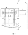
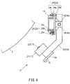
- FIG. 3 and FIG. 4 illustrate the enlarged scraper 13.
- the scraper 13 comprises a scraper body (scraper plate) 15 separately arranged above the grinding surface 2a of the rotary table 2, a mobilizing means 16 for allowing the scraper body 15 to move in a direction away from the grinding surface 2a when the material on the grinding surface 2a comes into contact with the scraper body 15, and a resistance adding means 17 ( FIG. 4 ) for adding resistance force to the movement of the scraper body 15 in the direction away from the grinding surface 2a.
- the mobilizing means 16 is configured so as to hang the scraper body 15 so that it can swing about a horizontal axis.
- the mobilizing means 16 has a turning shaft 18 extending in the horizontal direction, and the turning shaft 18 is turnably supported by a bearing 19 provided to the support beam 14.
- a plurality of movable support members (movable body) 20 extending in a vertical direction are provided to the turning shaft 18, and the movable support member 20 can swing about the turning shaft 18.
- the scraper body 15 is provided to a lower end of the movable support member 20, and the scraper body 15 can swing together with the movable support member 20.
- a contact surface 15a with the material of the scraper body 15 is oriented obliquely downward in a stationary state (state in the lowest position)of the scraper body 15.
- the contact surface 15a of the scraper body 15 forms an angle of 15 - 75 degrees, preferably 45 degrees with respect to the vertical surface.
- a lower portion of the contact surface 15a of the scraper body 15 is formed thick-walled.
- the resistance adding means 17 of the scraper 13 has a weight 21 pressing the scraper body 15 downward.
- the weight 21 is detachably mounted to a lower end portion of the movable support member 20 by a bolt 22.
- the weight 21 is configured by superposing a plurality of plates, and weight of the weight 21 can be adjusted by changing the number and kind of the plates.
- the scraper 13 further has a movable range limit means 23 for limiting an operable range of the scraper body 15.
- the movable range limit means 23 has a first stopper member 24 for defining a lowest position of the scraper 15 and a second stopper member 25 for defining a highest position of the scraper 15.
- the first stopper member 24 has a bolt support piece 24a provided to an upper surface of the support beam 14, a stopper bolt 24b screwed to a bolt hole formed in the bolt support piece 24a, and a bolt fixing nut 24c for releasably fixing the stopper bolt 24b.
- a distal end portion of the stopper bolt 24b abuts on the upper end portion of the movable support member 20 positioned above the turning shaft 18, in the stationary state of the movable support member 20 as illustrated in FIG. 4 .
- the movable support member 20 is limited in rotatively moving in a counterclockwise direction in FIG. 4 about the turning shaft 18.
- the limit position of the rotary movement of the movable support member 20 in the counterclockwise direction in FIG. 4 can be adjusted by adjusting a protruding amount of the stopper bolt 24b by loosening the bolt fixing nut 24c. Thereby, the lowest position of the scraper body 15 can be adjusted.
- the distal end portion of the stopper bolt 24b abuts on the upper end portion of the movable support member 20 and the movable support member 20 becomes stationary, in a state that the upper half portion of the movable support member 20 is oriented in the vertical direction.
- the material contact surface 15a of the scraper body 15 is inclined at 15 - 75 degrees, preferably 45 degrees toward the grinding roller 3 side with respect to the vertical direction, when the movable support member 20 is in the stationary state.
- the second stopper member 25 has a bolt support piece 25a provided to a lower surface of the support beam 14, a stopper bolt 25b screwed to a bolt hole formed in the bolt support piece 25a, and a bolt fixing nut 25c for releasably fixing the stopper bolt 25b.
- the limit position of the rotary movement of the movable support member 20 in the clockwise direction in FIG. 4 can be adjusted by adjusting a protruding amount of the stopper bolt 25b by loosening the bolt fixing nut 25c. Thereby, the highest position of the scraper body 15 can be adjusted.
- the movable support member 20 abuts on the support beam 14 and stops at the position, as illustrated in FIG. 6 . Thereby, a movable portion (weight 21, for example) of the scraper 13 can be surely prevented from coming into contact with the grinding roller 3.
- a dust cover 26 illustrated in FIG. 7 is provided around the mobilizing means 16 (18, 19) of the scraper 13. By providing the dust cover 26, dust can be prevented from adhering to the circumference of the turning shaft 18 of the scraper 13, thereby malfunction of the scraper 13 can be prevented.
- a scraper body 101 of a conventional scraper 100 is fixedly installed by a fixing bolt 103 via a fixed support member 102 on a biting side of the grinding roller 3.
- a distance D between a lower end of the scraper body 101 and the grinding surface 2a of the rotary table 2 is always constant.
- the distance D between the lower end of the scraper body 101 and the grinding surface 2a of the rotary table 2 does not change.
- the scraper body 15 is hanged so as to swing about the turning shaft 18 by the movable support member 20. Therefore, when the scraper body 15 is pressed by the material moving accompanied with the rotation of the rotary table 2, the scraper body 15 rotates about the turning shaft 18 together with the movable support member 20, if the pressing force exceeds the resistance force of the weight 21. By this rotation movement, the distance D between the lower end of the scraper body 15 and the grinding surface 2a of the rotary table 2 is expanded.
- an angular displacement amount of the movable support member 20 and the scraper body 15 about the turning shaft 18 is increased by increase in layer thickness T of the material on the upstream side of the scraper 13, and the distance D between the lower end of the scraper body 15 and the grinding surface 2a of the rotary table 2 is further expanded.
- the distance D between the lower end of the scraper body 15 and the grinding surface 2a of the rotary table 2 changes following fluctuation in layer thickness T of the material on the upstream side of the scraper 13.
- the height position of the scraper body 15 is automatically adjusted to an optimal position corresponding to the layer thickness of the material.
- the material contact surface 15a of the scraper 15 is inclined with respect to the vertical surface, and thereby the material is pressed in a direction of the grinding surface 2a of the rotary table 2 by the material contact surface 15a and compressed.
- this compression effect of the material by the material contact surface 15a part of air included inside the material is driven out.
- grinding work of the material by the grinding roller 3 can be stabilized and grinding efficiency can be increased.
- weight 21 is used as the resistance adding means 17 of the scraper 13 in the above-stated embodiment, a resilient member such as a spring member, an air dumper, or the like also can be used instead of the weight 21.
- a movable support member 20 in a bended shape is used in the above-stated embodiment, instead, a movable support member in a straight form may be used so that the material contact surface 15a of the scraper body 15 in a stationary state is oriented the vertical direction.
- the material contact surface 15a of the scraper body 15 is inclined with respect to the vertical surface since the scraper body 15 is rotated together with the movable support member by the pressing force from the material, and therefore the deaeration from the material and consolidation effect resulting from the compression effect of the material by the material contact surface 15a can be expected.
Landscapes
- Engineering & Computer Science (AREA)
- Food Science & Technology (AREA)
- Crushing And Grinding (AREA)
Abstract
Description
- The present invention relates to a vertical roller mill in which material is bitten and grinded between a grinding roller and a rotary table.
- Conventionally, a vertical roller mill in which material is bitten and grinded between a grinding roller and a rotary table has been used for grinding clinker, slag, and the like. In the vertical roller mill, material consisting of slag, clinker, and the like is supplied onto a center portion of the rotary table via a material charge chute. The rotary table is rotatively driven about a vertical rotation axis.
- The material supplied on the center portion of the rotary table is moved outward in a radial direction by centrifugal force generated by rotation of the rotary table, and supplied onto an annular grinding surface formed on the rotary table.
- Additionally, a separator is provided above the rotary table inside a mill casing, and material (coarse grain) whose grain size (grain diameter) is larger than a prescribed grain size is classified by the separator and recirculated onto the center portion of the rotary table. The material (coarse grain) recirculated on the center portion of the rotary table is supplied onto the grinding surface of the rotary table together with materials charged from the material charge chute by centrifugal force of the rotary table.
- The material supplied on the annular grinding surface of the rotary table is rotatively moved by rotary operation of the rotary table and bitten between a plurality of grinding rollers and the rotary table. Each of the plurality of grinding rollers is elastically pressed against the grinding surface of the rotary table by a roller pressing mechanism having a hydraulic cylinder or the like. The material bitten between the grinding roller and the rotary table is grinded by the pressing force of the grinding roller.
- Now, in a grinding process of cement, slag, and the like using the vertical roller mill, when thickness of the material to be grinded (layer thickness) on the annular grinding surface of the rotary table is not constant, the grinding roller is moved vertically due to fluctuation in layer thickness. The vertical movement of the grinding roller causes vibrations of the mill, which adversely affects a stable operation of the mill.
- In order to cope with this problem, in a conventional vertical roller mill, a scraper is provided on the biting side of the grinding roller. The scraper is provided above the grinding surface of the rotary table at a predetermined distance and fixed to a support beam above the rotary table.
- The scraper uniformizes the layer thickness by leveling the material before the material is bitten between the grinding roller and the rotary table, thereby reducing the mill vibration upon grinding caused by the fluctuation in layer thickness of the material.
- Patent Document 1: Japanese Patent Application Laid-open No.
H03-174258 - Now, the layer thickness of the material supplied on the grinding surface of the rotary table fluctuates depending on production model, production quantity, and operation parameter (such as material charge quantity and the like), and the scraper has an optimal height according to the layer thickness.
- However, since a conventional scraper is fixedly placed above the rotary table as stated above, work for changing its height needs to be performed during operation stop of the mill. Thus, operation efficiency of the mill is declined if the mill is temporarily stopped every time the layer thickness fluctuates for performing the adjustment work of scraper height.
- The present invention is made considering the above-stated problems of the conventional technique, and its object is to provide a vertical roller mill in which a height position of the scraper is automatically adjusted according to fluctuation in layer thickness when the layer thickness of the material supplied on the grinding surface of the rotary table fluctuates.
- In order to achieve the above-mentioned object, a vertical roller mill according to a first aspect of the present invention comprises: a rotary table having a grinding surface; a grinding roller for biting and grinding a material between the grinding surface and the same; and a scraper for adjusting a layer thickness of the material supplied to the grinding roller, wherein the scraper has: a scraper body separately arranged above the grinding surface; a mobilizing means for allowing the scraper body to move in a direction away from the grinding surface; and a resistance adding means for adding a resistance force to a movement of the scraper body in the direction away from the grinding surface.
- A second aspect of the present invention is that, in the first invention, the mobilizing means is configured to hang the scraper body so as to swing about a horizontal axis.
- A third aspect of the present invention is that, in the first or second aspect, the scraper body has a contact surface with the material, and the contact surface is oriented obliquely downward in a stationary state of the scraper body.
- A fourth aspect of the present invention is that, in the third aspect, the contact surface of the scraper body forms an angle of 15 - 75 degrees with respect to a vertical surface.
- A fifth aspect of the present invention is that, in any one of the first to fourth aspects, the resistance adding means has a weight for pressing the scraper body downward.
- A sixth aspect of the present invention is that, in the fifth aspect, the weight is adjustable in weight.
- A seventh aspect of the present invention is that, in any one of the first to sixth aspects, the scraper further has a movable range limit means for limiting an operable range of the scraper body.
- An eighth aspect of the present invention is that, in the seventh aspect, the movable range limit means is configured to be able to adjust a lowest position and a highest position of the scraper body.
- A ninth aspect of the present invention further comprises, in any one of the first to eighth aspects, a dust cover provided around the mobilizing means.
- A tenth aspect of the present invention is that, in any one of the first to ninth aspects, the scraper body has a contact surface with the material, and a lower portion of the contact surface is formed thick-walled.
- An object of the present invention is to provide a vertical roller mill in which a height position of the scraper is automatically adjusted according to the fluctuation in layer thickness even when the layer thickness of the material supplied onto the grinding surface of the rotary table fluctuates.
-
-
FIG. 1 is a longitudinal section view illustrating a schematic configuration of a vertical roller mill according to one embodiment of the present invention. -
FIG. 2 is a plan view illustrating an arrangement of a movable scraper in the vertical roller mill inFIG. 1 . -
FIG. 3 is a front view illustrating the movable scraper in the vertical roller mill inFIG. 1 . -
FIG. 4 is a side view illustrating the movable scraper in the vertical roller mill inFIG. 1 . -
FIG. 5 is a side view illustrating operation of the movable scraper in the vertical roller mill inFIG. 1 . -
FIG. 6 is another side view illustrating operation of the movable scraper in the vertical roller mill inFIG. 1 . -
FIG. 7 is a perspective view illustrating a dust cover of the movable scraper in the vertical roller mill inFIG. 1 . -
FIG. 8 is a schematic view illustrating an effect of the movable scraper in the vertical roller mill inFIG. 1 . -
FIG. 9 is a schematic view illustrating an effect of a fixed scraper in a conventional vertical roller mill. - Hereunder, a vertical roller mill according to one embodiment of the present invention will be described with reference to the drawings.
- As illustrated in
FIG.1 , avertical roller mill 1 according to this embodiment has a rotary table 2 to which material is supplied onto a top surface center portion of the same, and a plurality of (three in this example)grinding rollers 3 for biting and grinding the material between the rotary table 2 and the same. The rotary table 2 is rotatively driven about a vertical rotation axis L0. - The plurality of
grinding rollers 3 are arranged at equal angular intervals on a virtual circumference about the vertical rotation axis L0 of the rotary table 2. Each of the plurality ofgrinding rollers 3 is pressed against anannular grinding surface 2a of the rotary table 2 illustrated inFIG. 2 by aroller pressing mechanism 4 comprising a driving source such as a hydraulic cylinder or the like. - The
vertical roller mill 1 comprises arotation driving source 5 and areduction gear 6 for the rotary table 2, and the rotary table 2 is installed above thereduction gear 6. - The rotary table 2 and the
grinding roller 3 are covered by amill casing 7. Material is supplied to the rotary table 2 through a rawmaterial supply chute 8 which is arranged such that it passes through themill casing 7. In this example, thematerial supply chute 8 is extended along the vertical rotation axis L0 of the rotary table 2. - A separator 9 is provided above the rotary table 2. Among the material emitted outward in the radial direction from the rotary table 2 by centrifugal force, the material grinded so that its grain is smaller than a prescribed grain size (grain diameter) is blown up by hot air supplied inside the
mill casing 7 through a hot air duct (not illustrated) and is transferred to the separator 9. - The separator 9 is rotatively driven by a
separator driving device 10 which is composed of an electric machinery or the like, and discharges, among the material blown by the hot air, only the material (refined grain) whose grain is smaller than a prescribed grain size (grain diameter) from a refined grain discharge duct (not illustrated) which is provided to an upper portion of themill casing 7. On the other hand, the material (coarse grain) whose grain is larger than the prescribed grain size (grain diameter) is classified by the separator 9 and returned onto the rotary table 2 through a funnel shaped member (inner cone) 11 so as to be bitten and ground again by the grindingroller 3 and the rotary table 2. - The
vertical roller mill 1 comprises acollection casing 12 for collecting, among the material emitted around the rotary table 2 by the centrifugal force accompanied with the rotation of the rotary table, the material which was not blown up by the hot air. Thecollection casing 12 has a larger diameter than the rotary table 2, and assumes an annular form as a whole. The material collected by thecollection casing 12 is returned onto the rotary table 2 through an external circulation line (not illustrated) and grinded again. - As illustrated in
FIG. 2 , thevertical roller mill 1 according to this embodiment comprises three grindingrollers 3, and ascraper 13 for adjusting layer thickness of the material supplied to the grindingroller 3 is installed to each of the three grindingrollers 3. Thescraper 13 is provided to asupport beam 14 installed inside themill casing 7. -
FIG. 3 andFIG. 4 illustrate theenlarged scraper 13. Thescraper 13 comprises a scraper body (scraper plate) 15 separately arranged above the grindingsurface 2a of the rotary table 2, a mobilizingmeans 16 for allowing thescraper body 15 to move in a direction away from the grindingsurface 2a when the material on the grindingsurface 2a comes into contact with thescraper body 15, and a resistance adding means 17 (FIG. 4 ) for adding resistance force to the movement of thescraper body 15 in the direction away from the grindingsurface 2a. - The mobilizing means 16 is configured so as to hang the
scraper body 15 so that it can swing about a horizontal axis. Thus, the mobilizingmeans 16 has a turningshaft 18 extending in the horizontal direction, and the turningshaft 18 is turnably supported by abearing 19 provided to thesupport beam 14. A plurality of movable support members (movable body) 20 extending in a vertical direction are provided to the turningshaft 18, and themovable support member 20 can swing about the turningshaft 18. Thescraper body 15 is provided to a lower end of themovable support member 20, and thescraper body 15 can swing together with themovable support member 20. - As illustrated in
FIG. 4 , acontact surface 15a with the material of thescraper body 15 is oriented obliquely downward in a stationary state (state in the lowest position)of thescraper body 15. Specifically, thecontact surface 15a of thescraper body 15 forms an angle of 15 - 75 degrees, preferably 45 degrees with respect to the vertical surface. Considering wear due to contact with the material, a lower portion of thecontact surface 15a of thescraper body 15 is formed thick-walled. - The resistance adding means 17 of the
scraper 13 has aweight 21 pressing thescraper body 15 downward. Theweight 21 is detachably mounted to a lower end portion of themovable support member 20 by abolt 22. Theweight 21 is configured by superposing a plurality of plates, and weight of theweight 21 can be adjusted by changing the number and kind of the plates. - The
scraper 13 further has a movable range limit means 23 for limiting an operable range of thescraper body 15. The movable range limit means 23 has afirst stopper member 24 for defining a lowest position of thescraper 15 and asecond stopper member 25 for defining a highest position of thescraper 15. - The
first stopper member 24 has abolt support piece 24a provided to an upper surface of thesupport beam 14, astopper bolt 24b screwed to a bolt hole formed in thebolt support piece 24a, and abolt fixing nut 24c for releasably fixing thestopper bolt 24b. - A distal end portion of the
stopper bolt 24b abuts on the upper end portion of themovable support member 20 positioned above the turningshaft 18, in the stationary state of themovable support member 20 as illustrated inFIG. 4 . Thereby, themovable support member 20 is limited in rotatively moving in a counterclockwise direction inFIG. 4 about the turningshaft 18. - The limit position of the rotary movement of the
movable support member 20 in the counterclockwise direction inFIG. 4 can be adjusted by adjusting a protruding amount of thestopper bolt 24b by loosening thebolt fixing nut 24c. Thereby, the lowest position of thescraper body 15 can be adjusted. - In this example, as illustrated in
FIG. 4 , the distal end portion of thestopper bolt 24b abuts on the upper end portion of themovable support member 20 and themovable support member 20 becomes stationary, in a state that the upper half portion of themovable support member 20 is oriented in the vertical direction. Thereby, thematerial contact surface 15a of thescraper body 15 is inclined at 15 - 75 degrees, preferably 45 degrees toward the grindingroller 3 side with respect to the vertical direction, when themovable support member 20 is in the stationary state. - The
second stopper member 25 has abolt support piece 25a provided to a lower surface of thesupport beam 14, astopper bolt 25b screwed to a bolt hole formed in thebolt support piece 25a, and abolt fixing nut 25c for releasably fixing thestopper bolt 25b. - As illustrated in
FIG. 5 , when thescraper body 15 is pushed up by contact with the material and themovable support member 20 rotates in a clockwise direction inFIG. 4 about the turningshaft 18, a center portion of themovable support member 20 positioned below the turningshaft 18 abuts on a distal end portion of thestopper bolt 25b. Thereby, themovable support member 20 is limited in rotatively moving in a clockwise direction inFIG. 4 about the turningshaft 18. - The limit position of the rotary movement of the
movable support member 20 in the clockwise direction inFIG. 4 can be adjusted by adjusting a protruding amount of thestopper bolt 25b by loosening thebolt fixing nut 25c. Thereby, the highest position of thescraper body 15 can be adjusted. - Note that, even when the
lower stopper bolt 25b and thebolt support piece 25a are broken by a pressing force of the material, themovable support member 20 abuts on thesupport beam 14 and stops at the position, as illustrated inFIG. 6 . Thereby, a movable portion (weight 21, for example) of thescraper 13 can be surely prevented from coming into contact with the grindingroller 3. - A
dust cover 26 illustrated inFIG. 7 is provided around the mobilizing means 16 (18, 19) of thescraper 13. By providing thedust cover 26, dust can be prevented from adhering to the circumference of the turningshaft 18 of thescraper 13, thereby malfunction of thescraper 13 can be prevented. - Next, an effect of the
scraper 13 of thevertical roller mill 1 according to this embodiment will be described comparing with a conventional scraper. - As illustrated in
FIG. 9 , ascraper body 101 of aconventional scraper 100 is fixedly installed by a fixingbolt 103 via a fixedsupport member 102 on a biting side of the grindingroller 3. In this fixedscraper 100, a distance D between a lower end of thescraper body 101 and the grindingsurface 2a of the rotary table 2 is always constant. Thus, even when a layer thickness T of the material on an upstream side of thescraper 100 fluctuates, the distance D between the lower end of thescraper body 101 and the grindingsurface 2a of the rotary table 2 does not change. - In contrast, in the
scraper 13 of thevertical roller mill 1 according to this embodiment, thescraper body 15 is hanged so as to swing about the turningshaft 18 by themovable support member 20. Therefore, when thescraper body 15 is pressed by the material moving accompanied with the rotation of the rotary table 2, thescraper body 15 rotates about the turningshaft 18 together with themovable support member 20, if the pressing force exceeds the resistance force of theweight 21. By this rotation movement, the distance D between the lower end of thescraper body 15 and the grindingsurface 2a of the rotary table 2 is expanded. - Thus, in the
scraper 13 of thevertical roller mill 1 according to this embodiment, an angular displacement amount of themovable support member 20 and thescraper body 15 about the turningshaft 18 is increased by increase in layer thickness T of the material on the upstream side of thescraper 13, and the distance D between the lower end of thescraper body 15 and the grindingsurface 2a of the rotary table 2 is further expanded. - As described above, in the
vertical roller mill 1 according to this embodiment, the distance D between the lower end of thescraper body 15 and the grindingsurface 2a of the rotary table 2 changes following fluctuation in layer thickness T of the material on the upstream side of thescraper 13. Thereby, the height position of thescraper body 15 is automatically adjusted to an optimal position corresponding to the layer thickness of the material. - Additionally, in the
vertical roller mill 1 according to this embodiment, thematerial contact surface 15a of thescraper 15 is inclined with respect to the vertical surface, and thereby the material is pressed in a direction of the grindingsurface 2a of the rotary table 2 by thematerial contact surface 15a and compressed. By this compression effect of the material by thematerial contact surface 15a, part of air included inside the material is driven out. By this deaeration and consolidation effect of the material, grinding work of the material by the grindingroller 3 can be stabilized and grinding efficiency can be increased. - It is preferable to determine an inclination angle of the
material contact surface 15a of thescraper body 15 with respect to the vertical surface so as to achieve the above-mentioned deaeration and consolidation effect of the material and also to ensure a sufficient movable range of thescraper body 15 for keeping a necessary adjustment range. - Note that, although the
vertical roller mill 1 having the three grindingrollers 3 is described in the above-stated embodiment, any number of grinding rollers may be employed and four or more grinding rollers may be employed in the present invention. - Additionally, although the
weight 21 is used as the resistance adding means 17 of thescraper 13 in the above-stated embodiment, a resilient member such as a spring member, an air dumper, or the like also can be used instead of theweight 21. - Additionally, although the
movable support member 20 in a bended shape is used in the above-stated embodiment, instead, a movable support member in a straight form may be used so that thematerial contact surface 15a of thescraper body 15 in a stationary state is oriented the vertical direction. - Also in this case, the
material contact surface 15a of thescraper body 15 is inclined with respect to the vertical surface since thescraper body 15 is rotated together with the movable support member by the pressing force from the material, and therefore the deaeration from the material and consolidation effect resulting from the compression effect of the material by thematerial contact surface 15a can be expected. -
- 1 ... vertical roller mill
- 2 ... rotary table
- 2a ... grinding surface of rotary table
- 3 ... grinding roller
- 4 ... roller pressing mechanism
- 5 ... rotation driving source for rotary table
- 6 ... reduction gear for rotary table
- 7 ... mill casing
- 8 ... material supply chute
- 9 ... separator
- 10 .. separator driving device
- 11 ... funnel shaped member (inner cone)
- 12 ... collection casing
- 13 ... scraper
- 14 ... support beam
- 15 ... scraper body
- 15a ... material contact surface
- 16 ... mobilizing means
- 17 ... resistance adding means
- 18 ... turning shaft
- 19 ... bearing
- 20 ... movable support member
- 21 ... weight (resistance adding means)
- 22 ... bolt (for fixing weight)
- 23 ... movable range limit means
- 24 ... first stopper member
- 24a ... bolt support piece
- 24b .. stopper bolt
- 24c ... bolt fixing nut
- 25 ... second stopper member
- 25a ... bolt support piece
- 25b ... stopper bolt
- 25c ... bolt fixing nut
- 26 ... dust cover
- 100 ... conventional scraper
- 101 ... scraper body of conventional scraper
- 102 ... fixed support member of conventional scraper
- 103 .. fixing bolt of conventional scraper
- D ... distance between lower end of scraper body and grinding surface of rotary table
- L0 ... rotation axis of rotary table
- T ... layer thickness of material
Claims (10)
- A vertical roller mill, comprising:a rotary table having a grinding surface;a grinding roller for biting and grinding a material between the grinding surface and the grinding roller; anda scraper for adjusting a layer thickness of the material supplied to the grinding roller,wherein the scraper has:a scraper body separately arranged above the grinding surface;a mobilizing means for allowing the scraper body to move in a direction away from the grinding surface; anda resistance adding means for adding a resistance force to a movement of the scraper body in the direction away from the grinding surface.
- The vertical roller mill according to claim 1, wherein the mobilizing means is configured to hang the scraper body so as to swing about a horizontal axis.
- The vertical roller mill according to claim 1 or 2,
wherein the scraper body has a contact surface with the material, and
wherein the contact surface is oriented obliquely downward in a stationary state of the scraper body. - The vertical roller mill according to claim 3, wherein the contact surface of the scraper body forms an angle of 15 - 75 degrees with respect to a vertical surface.
- The vertical roller mill according to any one of claims 1 to 4, wherein the resistance adding means has a weight for pressing the scraper body downward.
- The vertical roller mill according to claim 5, wherein the weight is adjustable in its weight.
- The vertical roller mill according to any one of claims 1 to 6, wherein the scraper further has a movable range limit means for limiting an operable range of the scraper body.
- The vertical roller mill according to claim 7, wherein the movable range limit means is configured to be able to adjust a lowest position and a highest position of the scraper body.
- The vertical roller mill according to any one of claims 1 to 8, further comprising a dust cover provided over the mobilizing means.
- The vertical roller mill according to any one of claims 1 to 9,
wherein the scraper body has a contact surface with the material, and
wherein a lower portion of the contact surface is formed thick-walled.
Applications Claiming Priority (2)
| Application Number | Priority Date | Filing Date | Title |
|---|---|---|---|
| JP2014259383A JP6656805B2 (en) | 2014-12-22 | 2014-12-22 | Vertical roller mill |
| PCT/JP2015/084962 WO2016104224A1 (en) | 2014-12-22 | 2015-12-14 | Vertical roller mill |
Publications (3)
| Publication Number | Publication Date |
|---|---|
| EP3238824A1 true EP3238824A1 (en) | 2017-11-01 |
| EP3238824A4 EP3238824A4 (en) | 2018-09-19 |
| EP3238824B1 EP3238824B1 (en) | 2019-11-13 |
Family
ID=56147576
Family Applications (1)
| Application Number | Title | Priority Date | Filing Date |
|---|---|---|---|
| EP15872793.3A Active EP3238824B1 (en) | 2014-12-22 | 2015-12-14 | Vertical roller mill |
Country Status (4)
| Country | Link |
|---|---|
| EP (1) | EP3238824B1 (en) |
| JP (1) | JP6656805B2 (en) |
| CN (2) | CN105709884B (en) |
| WO (1) | WO2016104224A1 (en) |
Cited By (2)
| Publication number | Priority date | Publication date | Assignee | Title |
|---|---|---|---|---|
| WO2018228675A1 (en) * | 2017-06-13 | 2018-12-20 | Loesche Gmbh | Vertical roller mill |
| DE102019210047B3 (en) | 2019-07-08 | 2020-06-18 | Thyssenkrupp Ag | Vertical roller mill |
Families Citing this family (7)
| Publication number | Priority date | Publication date | Assignee | Title |
|---|---|---|---|---|
| JP6656805B2 (en) * | 2014-12-22 | 2020-03-04 | 川崎重工業株式会社 | Vertical roller mill |
| CN109692731A (en) * | 2019-02-22 | 2019-04-30 | 安徽海螺川崎节能设备制造有限公司 | A kind of cement vertical mill |
| DE112021006244T5 (en) * | 2020-12-01 | 2023-09-07 | Kawasaki Jukogyo Kabushiki Kaisha | EXHAUST AIR, VERTICAL MILL AND EXHAUST PROCESS |
| CN112742545A (en) * | 2021-02-04 | 2021-05-04 | 南京西普水泥工程集团有限公司 | Scraping plate |
| CN113171831B (en) * | 2021-04-23 | 2022-12-09 | 江西鑫吉食品有限公司 | Food production processing is with raw materials equipment of sieving that smashes |
| CN115301352B (en) * | 2022-08-12 | 2024-05-10 | 上海固柯科技有限公司 | A method for preparing epoxy resin |
| CN120094671B (en) * | 2025-05-08 | 2025-07-25 | 江苏鹏飞集团股份有限公司 | A full external circulation cement vertical mill |
Family Cites Families (11)
| Publication number | Priority date | Publication date | Assignee | Title |
|---|---|---|---|---|
| JPS614549A (en) * | 1984-06-18 | 1986-01-10 | 川崎重工業株式会社 | Vertical mill with scraper |
| JPH074545B2 (en) * | 1990-01-23 | 1995-01-25 | 宇部興産株式会社 | Vertical crusher |
| JPH0753247B2 (en) * | 1990-03-06 | 1995-06-07 | 宇部興産株式会社 | Vertical crusher |
| JPH09103697A (en) * | 1995-10-11 | 1997-04-22 | Babcock Hitachi Kk | Roller mill |
| JP3017449B2 (en) * | 1996-10-18 | 2000-03-06 | 株式会社栗本鐵工所 | Vertical mill |
| CN101125306A (en) * | 2007-10-09 | 2008-02-20 | 辽宁重机设备技术有限公司 | Roller type medium speed mill |
| CN102302968B (en) * | 2011-07-06 | 2013-04-24 | 郝志刚 | Vertical grinder and installation mechanism of scraping plate device of vertical grinder |
| JP5906782B2 (en) * | 2012-02-13 | 2016-04-20 | 宇部興産機械株式会社 | Vertical crusher |
| CN102784694B (en) * | 2012-08-16 | 2015-05-20 | 郝志刚 | vertical mill |
| JP2014091109A (en) * | 2012-11-06 | 2014-05-19 | Mitsubishi Heavy Ind Ltd | Roller mill device |
| JP6656805B2 (en) * | 2014-12-22 | 2020-03-04 | 川崎重工業株式会社 | Vertical roller mill |
-
2014
- 2014-12-22 JP JP2014259383A patent/JP6656805B2/en active Active
-
2015
- 2015-12-14 EP EP15872793.3A patent/EP3238824B1/en active Active
- 2015-12-14 WO PCT/JP2015/084962 patent/WO2016104224A1/en not_active Ceased
- 2015-12-22 CN CN201510969133.4A patent/CN105709884B/en active Active
- 2015-12-22 CN CN201521075743.1U patent/CN205599248U/en not_active Expired - Lifetime
Cited By (3)
| Publication number | Priority date | Publication date | Assignee | Title |
|---|---|---|---|---|
| WO2018228675A1 (en) * | 2017-06-13 | 2018-12-20 | Loesche Gmbh | Vertical roller mill |
| DE102019210047B3 (en) | 2019-07-08 | 2020-06-18 | Thyssenkrupp Ag | Vertical roller mill |
| WO2021004757A1 (en) | 2019-07-08 | 2021-01-14 | Thyssenkrupp Industrial Solutions Ag | Vertical roller mill |
Also Published As
| Publication number | Publication date |
|---|---|
| JP2016117042A (en) | 2016-06-30 |
| EP3238824B1 (en) | 2019-11-13 |
| JP6656805B2 (en) | 2020-03-04 |
| CN105709884A (en) | 2016-06-29 |
| EP3238824A4 (en) | 2018-09-19 |
| CN205599248U (en) | 2016-09-28 |
| WO2016104224A1 (en) | 2016-06-30 |
| CN105709884B (en) | 2019-03-26 |
Similar Documents
| Publication | Publication Date | Title |
|---|---|---|
| EP3238824B1 (en) | Vertical roller mill | |
| US11369973B2 (en) | Method and device for milling and separation of solids and granular materials including metal containing materials as well as phytogenic materials with high level of silicon in a controlled airflow | |
| CN205850976U (en) | A kind of Ore pulverizing bucket | |
| JP2013163171A (en) | Vertical grinder | |
| CN204352937U (en) | A kind of slag mill | |
| TWI436830B (en) | Roller mill | |
| CN108499669A (en) | Paddle type mill dynamic circulation screening crusher | |
| JP2016203076A (en) | Vertical crusher and operation method thereof | |
| CN105855030B (en) | Ceramic raw material roller mill electromagnetic vibration screening return device | |
| CN109317401A (en) | A kind of rocking chemical material screening machine | |
| CN104249007A (en) | Polishing machine | |
| CN104707690A (en) | Oblique swing pressurization external circulation mill | |
| CN103721798A (en) | Oblique-swinging waterfall-discharging type grinder | |
| KR101634763B1 (en) | Vertical pulverizing apparatus | |
| US2132508A (en) | Cone crusher | |
| CN107225087A (en) | A kind of vertical sand making machine Shai Zhen mechanisms | |
| JP2016150300A (en) | Vertical crusher | |
| CN105499134B (en) | A kind of automatic charging is classified blowing machine triumphantly | |
| JP6497079B2 (en) | Vertical crusher | |
| CN104984793B (en) | It is inserted into the high frequency linear vibration tube-type batcher of dynamic device feed pore | |
| CN209715261U (en) | A kind of abrasive disk type sand making machine | |
| US20160303572A1 (en) | Adjustable Dwell Shredder | |
| JP2022006219A (en) | Vertical mill | |
| CN224253449U (en) | Vibration feeding device | |
| JPWO2015193959A1 (en) | Vertical roller mill |
Legal Events
| Date | Code | Title | Description |
|---|---|---|---|
| STAA | Information on the status of an ep patent application or granted ep patent |
Free format text: STATUS: THE INTERNATIONAL PUBLICATION HAS BEEN MADE |
|
| PUAI | Public reference made under article 153(3) epc to a published international application that has entered the european phase |
Free format text: ORIGINAL CODE: 0009012 |
|
| STAA | Information on the status of an ep patent application or granted ep patent |
Free format text: STATUS: REQUEST FOR EXAMINATION WAS MADE |
|
| 17P | Request for examination filed |
Effective date: 20170721 |
|
| AK | Designated contracting states |
Kind code of ref document: A1 Designated state(s): AL AT BE BG CH CY CZ DE DK EE ES FI FR GB GR HR HU IE IS IT LI LT LU LV MC MK MT NL NO PL PT RO RS SE SI SK SM TR |
|
| AX | Request for extension of the european patent |
Extension state: BA ME |
|
| DAV | Request for validation of the european patent (deleted) | ||
| DAX | Request for extension of the european patent (deleted) | ||
| A4 | Supplementary search report drawn up and despatched |
Effective date: 20180817 |
|
| RIC1 | Information provided on ipc code assigned before grant |
Ipc: B02C 15/00 20060101ALI20180810BHEP Ipc: B02C 15/04 20060101AFI20180810BHEP |
|
| GRAP | Despatch of communication of intention to grant a patent |
Free format text: ORIGINAL CODE: EPIDOSNIGR1 |
|
| STAA | Information on the status of an ep patent application or granted ep patent |
Free format text: STATUS: GRANT OF PATENT IS INTENDED |
|
| INTG | Intention to grant announced |
Effective date: 20190605 |
|
| GRAS | Grant fee paid |
Free format text: ORIGINAL CODE: EPIDOSNIGR3 |
|
| GRAA | (expected) grant |
Free format text: ORIGINAL CODE: 0009210 |
|
| STAA | Information on the status of an ep patent application or granted ep patent |
Free format text: STATUS: THE PATENT HAS BEEN GRANTED |
|
| AK | Designated contracting states |
Kind code of ref document: B1 Designated state(s): AL AT BE BG CH CY CZ DE DK EE ES FI FR GB GR HR HU IE IS IT LI LT LU LV MC MK MT NL NO PL PT RO RS SE SI SK SM TR |
|
| REG | Reference to a national code |
Ref country code: CH Ref legal event code: EP Ref country code: AT Ref legal event code: REF Ref document number: 1201110 Country of ref document: AT Kind code of ref document: T Effective date: 20191115 |
|
| REG | Reference to a national code |
Ref country code: DE Ref legal event code: R096 Ref document number: 602015041821 Country of ref document: DE |
|
| REG | Reference to a national code |
Ref country code: IE Ref legal event code: FG4D |
|
| REG | Reference to a national code |
Ref country code: NL Ref legal event code: MP Effective date: 20191113 |
|
| REG | Reference to a national code |
Ref country code: LT Ref legal event code: MG4D |
|
| PG25 | Lapsed in a contracting state [announced via postgrant information from national office to epo] |
Ref country code: LV Free format text: LAPSE BECAUSE OF FAILURE TO SUBMIT A TRANSLATION OF THE DESCRIPTION OR TO PAY THE FEE WITHIN THE PRESCRIBED TIME-LIMIT Effective date: 20191113 Ref country code: SE Free format text: LAPSE BECAUSE OF FAILURE TO SUBMIT A TRANSLATION OF THE DESCRIPTION OR TO PAY THE FEE WITHIN THE PRESCRIBED TIME-LIMIT Effective date: 20191113 Ref country code: NO Free format text: LAPSE BECAUSE OF FAILURE TO SUBMIT A TRANSLATION OF THE DESCRIPTION OR TO PAY THE FEE WITHIN THE PRESCRIBED TIME-LIMIT Effective date: 20200213 Ref country code: PT Free format text: LAPSE BECAUSE OF FAILURE TO SUBMIT A TRANSLATION OF THE DESCRIPTION OR TO PAY THE FEE WITHIN THE PRESCRIBED TIME-LIMIT Effective date: 20200313 Ref country code: LT Free format text: LAPSE BECAUSE OF FAILURE TO SUBMIT A TRANSLATION OF THE DESCRIPTION OR TO PAY THE FEE WITHIN THE PRESCRIBED TIME-LIMIT Effective date: 20191113 Ref country code: PL Free format text: LAPSE BECAUSE OF FAILURE TO SUBMIT A TRANSLATION OF THE DESCRIPTION OR TO PAY THE FEE WITHIN THE PRESCRIBED TIME-LIMIT Effective date: 20191113 Ref country code: GR Free format text: LAPSE BECAUSE OF FAILURE TO SUBMIT A TRANSLATION OF THE DESCRIPTION OR TO PAY THE FEE WITHIN THE PRESCRIBED TIME-LIMIT Effective date: 20200214 Ref country code: NL Free format text: LAPSE BECAUSE OF FAILURE TO SUBMIT A TRANSLATION OF THE DESCRIPTION OR TO PAY THE FEE WITHIN THE PRESCRIBED TIME-LIMIT Effective date: 20191113 Ref country code: FI Free format text: LAPSE BECAUSE OF FAILURE TO SUBMIT A TRANSLATION OF THE DESCRIPTION OR TO PAY THE FEE WITHIN THE PRESCRIBED TIME-LIMIT Effective date: 20191113 Ref country code: BG Free format text: LAPSE BECAUSE OF FAILURE TO SUBMIT A TRANSLATION OF THE DESCRIPTION OR TO PAY THE FEE WITHIN THE PRESCRIBED TIME-LIMIT Effective date: 20200213 |
|
| PG25 | Lapsed in a contracting state [announced via postgrant information from national office to epo] |
Ref country code: IS Free format text: LAPSE BECAUSE OF FAILURE TO SUBMIT A TRANSLATION OF THE DESCRIPTION OR TO PAY THE FEE WITHIN THE PRESCRIBED TIME-LIMIT Effective date: 20200313 Ref country code: HR Free format text: LAPSE BECAUSE OF FAILURE TO SUBMIT A TRANSLATION OF THE DESCRIPTION OR TO PAY THE FEE WITHIN THE PRESCRIBED TIME-LIMIT Effective date: 20191113 Ref country code: RS Free format text: LAPSE BECAUSE OF FAILURE TO SUBMIT A TRANSLATION OF THE DESCRIPTION OR TO PAY THE FEE WITHIN THE PRESCRIBED TIME-LIMIT Effective date: 20191113 |
|
| PG25 | Lapsed in a contracting state [announced via postgrant information from national office to epo] |
Ref country code: AL Free format text: LAPSE BECAUSE OF FAILURE TO SUBMIT A TRANSLATION OF THE DESCRIPTION OR TO PAY THE FEE WITHIN THE PRESCRIBED TIME-LIMIT Effective date: 20191113 |
|
| PG25 | Lapsed in a contracting state [announced via postgrant information from national office to epo] |
Ref country code: EE Free format text: LAPSE BECAUSE OF FAILURE TO SUBMIT A TRANSLATION OF THE DESCRIPTION OR TO PAY THE FEE WITHIN THE PRESCRIBED TIME-LIMIT Effective date: 20191113 Ref country code: DK Free format text: LAPSE BECAUSE OF FAILURE TO SUBMIT A TRANSLATION OF THE DESCRIPTION OR TO PAY THE FEE WITHIN THE PRESCRIBED TIME-LIMIT Effective date: 20191113 Ref country code: RO Free format text: LAPSE BECAUSE OF FAILURE TO SUBMIT A TRANSLATION OF THE DESCRIPTION OR TO PAY THE FEE WITHIN THE PRESCRIBED TIME-LIMIT Effective date: 20191113 Ref country code: CZ Free format text: LAPSE BECAUSE OF FAILURE TO SUBMIT A TRANSLATION OF THE DESCRIPTION OR TO PAY THE FEE WITHIN THE PRESCRIBED TIME-LIMIT Effective date: 20191113 Ref country code: ES Free format text: LAPSE BECAUSE OF FAILURE TO SUBMIT A TRANSLATION OF THE DESCRIPTION OR TO PAY THE FEE WITHIN THE PRESCRIBED TIME-LIMIT Effective date: 20191113 |
|
| REG | Reference to a national code |
Ref country code: CH Ref legal event code: PL |
|
| REG | Reference to a national code |
Ref country code: DE Ref legal event code: R097 Ref document number: 602015041821 Country of ref document: DE |
|
| REG | Reference to a national code |
Ref country code: AT Ref legal event code: MK05 Ref document number: 1201110 Country of ref document: AT Kind code of ref document: T Effective date: 20191113 |
|
| REG | Reference to a national code |
Ref country code: BE Ref legal event code: MM Effective date: 20191231 |
|
| PG25 | Lapsed in a contracting state [announced via postgrant information from national office to epo] |
Ref country code: SM Free format text: LAPSE BECAUSE OF FAILURE TO SUBMIT A TRANSLATION OF THE DESCRIPTION OR TO PAY THE FEE WITHIN THE PRESCRIBED TIME-LIMIT Effective date: 20191113 Ref country code: MC Free format text: LAPSE BECAUSE OF FAILURE TO SUBMIT A TRANSLATION OF THE DESCRIPTION OR TO PAY THE FEE WITHIN THE PRESCRIBED TIME-LIMIT Effective date: 20191113 Ref country code: SK Free format text: LAPSE BECAUSE OF FAILURE TO SUBMIT A TRANSLATION OF THE DESCRIPTION OR TO PAY THE FEE WITHIN THE PRESCRIBED TIME-LIMIT Effective date: 20191113 |
|
| PLBE | No opposition filed within time limit |
Free format text: ORIGINAL CODE: 0009261 |
|
| STAA | Information on the status of an ep patent application or granted ep patent |
Free format text: STATUS: NO OPPOSITION FILED WITHIN TIME LIMIT |
|
| 26N | No opposition filed |
Effective date: 20200814 |
|
| GBPC | Gb: european patent ceased through non-payment of renewal fee |
Effective date: 20200213 |
|
| PG25 | Lapsed in a contracting state [announced via postgrant information from national office to epo] |
Ref country code: FR Free format text: LAPSE BECAUSE OF NON-PAYMENT OF DUE FEES Effective date: 20200113 Ref country code: IE Free format text: LAPSE BECAUSE OF NON-PAYMENT OF DUE FEES Effective date: 20191214 Ref country code: LU Free format text: LAPSE BECAUSE OF NON-PAYMENT OF DUE FEES Effective date: 20191214 |
|
| PG25 | Lapsed in a contracting state [announced via postgrant information from national office to epo] |
Ref country code: BE Free format text: LAPSE BECAUSE OF NON-PAYMENT OF DUE FEES Effective date: 20191231 Ref country code: CH Free format text: LAPSE BECAUSE OF NON-PAYMENT OF DUE FEES Effective date: 20191231 Ref country code: LI Free format text: LAPSE BECAUSE OF NON-PAYMENT OF DUE FEES Effective date: 20191231 Ref country code: AT Free format text: LAPSE BECAUSE OF FAILURE TO SUBMIT A TRANSLATION OF THE DESCRIPTION OR TO PAY THE FEE WITHIN THE PRESCRIBED TIME-LIMIT Effective date: 20191113 Ref country code: SI Free format text: LAPSE BECAUSE OF FAILURE TO SUBMIT A TRANSLATION OF THE DESCRIPTION OR TO PAY THE FEE WITHIN THE PRESCRIBED TIME-LIMIT Effective date: 20191113 |
|
| PG25 | Lapsed in a contracting state [announced via postgrant information from national office to epo] |
Ref country code: IT Free format text: LAPSE BECAUSE OF FAILURE TO SUBMIT A TRANSLATION OF THE DESCRIPTION OR TO PAY THE FEE WITHIN THE PRESCRIBED TIME-LIMIT Effective date: 20191113 Ref country code: GB Free format text: LAPSE BECAUSE OF NON-PAYMENT OF DUE FEES Effective date: 20200213 |
|
| PG25 | Lapsed in a contracting state [announced via postgrant information from national office to epo] |
Ref country code: CY Free format text: LAPSE BECAUSE OF FAILURE TO SUBMIT A TRANSLATION OF THE DESCRIPTION OR TO PAY THE FEE WITHIN THE PRESCRIBED TIME-LIMIT Effective date: 20191113 |
|
| PG25 | Lapsed in a contracting state [announced via postgrant information from national office to epo] |
Ref country code: MT Free format text: LAPSE BECAUSE OF FAILURE TO SUBMIT A TRANSLATION OF THE DESCRIPTION OR TO PAY THE FEE WITHIN THE PRESCRIBED TIME-LIMIT Effective date: 20191113 Ref country code: HU Free format text: LAPSE BECAUSE OF FAILURE TO SUBMIT A TRANSLATION OF THE DESCRIPTION OR TO PAY THE FEE WITHIN THE PRESCRIBED TIME-LIMIT; INVALID AB INITIO Effective date: 20151214 |
|
| PG25 | Lapsed in a contracting state [announced via postgrant information from national office to epo] |
Ref country code: TR Free format text: LAPSE BECAUSE OF FAILURE TO SUBMIT A TRANSLATION OF THE DESCRIPTION OR TO PAY THE FEE WITHIN THE PRESCRIBED TIME-LIMIT Effective date: 20191113 |
|
| PG25 | Lapsed in a contracting state [announced via postgrant information from national office to epo] |
Ref country code: MK Free format text: LAPSE BECAUSE OF FAILURE TO SUBMIT A TRANSLATION OF THE DESCRIPTION OR TO PAY THE FEE WITHIN THE PRESCRIBED TIME-LIMIT Effective date: 20191113 |
|
| PGFP | Annual fee paid to national office [announced via postgrant information from national office to epo] |
Ref country code: DE Payment date: 20251028 Year of fee payment: 11 |