EP3238192B1 - Procédé et dispositif destinés à fournir une alarme - Google Patents
Procédé et dispositif destinés à fournir une alarme Download PDFInfo
- Publication number
- EP3238192B1 EP3238192B1 EP15813071.6A EP15813071A EP3238192B1 EP 3238192 B1 EP3238192 B1 EP 3238192B1 EP 15813071 A EP15813071 A EP 15813071A EP 3238192 B1 EP3238192 B1 EP 3238192B1
- Authority
- EP
- European Patent Office
- Prior art keywords
- housing
- component
- alarm
- person
- coupled
- Prior art date
- Legal status (The legal status is an assumption and is not a legal conclusion. Google has not performed a legal analysis and makes no representation as to the accuracy of the status listed.)
- Active
Links
- 238000000034 method Methods 0.000 title description 12
- 239000013013 elastic material Substances 0.000 claims description 7
- 230000001419 dependent effect Effects 0.000 claims description 6
- 239000004020 conductor Substances 0.000 claims description 5
- 230000000007 visual effect Effects 0.000 claims description 4
- 210000000707 wrist Anatomy 0.000 claims description 4
- 210000004247 hand Anatomy 0.000 claims description 3
- 230000004913 activation Effects 0.000 claims 1
- 239000000463 material Substances 0.000 description 9
- 238000005516 engineering process Methods 0.000 description 5
- 230000035945 sensitivity Effects 0.000 description 4
- 230000009429 distress Effects 0.000 description 3
- 230000035882 stress Effects 0.000 description 3
- 238000005452 bending Methods 0.000 description 2
- 238000004891 communication Methods 0.000 description 2
- 238000001514 detection method Methods 0.000 description 2
- 238000010586 diagram Methods 0.000 description 2
- 239000002305 electric material Substances 0.000 description 2
- 230000000977 initiatory effect Effects 0.000 description 2
- 239000002245 particle Substances 0.000 description 2
- 230000003213 activating effect Effects 0.000 description 1
- 230000001413 cellular effect Effects 0.000 description 1
- 230000006835 compression Effects 0.000 description 1
- 238000007906 compression Methods 0.000 description 1
- 238000010276 construction Methods 0.000 description 1
- 238000006073 displacement reaction Methods 0.000 description 1
- 230000000694 effects Effects 0.000 description 1
- 230000005489 elastic deformation Effects 0.000 description 1
- 230000014509 gene expression Effects 0.000 description 1
- 238000012886 linear function Methods 0.000 description 1
- 238000005259 measurement Methods 0.000 description 1
Images


Classifications
-
- G—PHYSICS
- G08—SIGNALLING
- G08B—SIGNALLING OR CALLING SYSTEMS; ORDER TELEGRAPHS; ALARM SYSTEMS
- G08B21/00—Alarms responsive to a single specified undesired or abnormal condition and not otherwise provided for
- G08B21/02—Alarms for ensuring the safety of persons
-
- G—PHYSICS
- G08—SIGNALLING
- G08B—SIGNALLING OR CALLING SYSTEMS; ORDER TELEGRAPHS; ALARM SYSTEMS
- G08B25/00—Alarm systems in which the location of the alarm condition is signalled to a central station, e.g. fire or police telegraphic systems
- G08B25/008—Alarm setting and unsetting, i.e. arming or disarming of the security system
-
- G—PHYSICS
- G08—SIGNALLING
- G08B—SIGNALLING OR CALLING SYSTEMS; ORDER TELEGRAPHS; ALARM SYSTEMS
- G08B25/00—Alarm systems in which the location of the alarm condition is signalled to a central station, e.g. fire or police telegraphic systems
- G08B25/01—Alarm systems in which the location of the alarm condition is signalled to a central station, e.g. fire or police telegraphic systems characterised by the transmission medium
Definitions
- the invention is related to a method and device for providing an alarm on request of a person wearing the device and to a personal emergency response system comprising the device, wherein the device is attachable to the body of the person.
- PERS devices personal emergency response systems or devices, also referred to as PERS devices, promote the independence and improve the quality of lives of elderly and disabled members of the population by providing "anytime-anywhere" access to assistance provided by family or a professional alarm control center.
- Anywhere access means that the PERS device requires technologies that allow the service provider to communicate with and possibly locate the incapacitated person. Such technologies include communication technologies such as cellular, Wi-Fi, Bluetooth; and location technologies make (for example) use of a global positioning system (GPS) or Wi-Fi.
- GPS global positioning system
- Wi-Fi Wireless Fidelity
- US2009121863 and US20140150530A1 disclose wearable PERS devices that have communication technologies for sending a help request to a professional alarm control center.
- the documents US2010148975 and US2004080421 describe further examples of alarm devices.
- US20090121863 discloses a PERS device containing an emergency button that the person can press to call for help. However, in an emergency situation, the person may panic and be confused making it difficult for the person to properly press the emergency push button.
- the invention is defined by the appended claims.
- the person is wearing the device, for example, by attaching it to the wrist or other part of the body.
- the person may simply pull the device that is attached (with attaching means such as a cord, strap or belt) to the body of the person. Due to the imposed pulling force, an electrical characteristic of the component has changed. The change of the electrical characteristic is measured and when detected, it will result in the activating of the alarm.
- attaching means such as a cord, strap or belt
- time filter is used to prevent that an accidental pulling of the device causes an alarm. It may happen, for example, when the device accidentally hooks or is caught on an object (e.g. a table) during standing up that the exerted pulling force causes a change in the electrical characteristic.
- the time filter requires the pulling force to be present for a predetermined time period to be able to cause an alarm. Accidental pulling of the device shorter than the predetermined time period will not initiate an alarm, and thus there will be fewer false alarms.
- the alarm is already activated, the person is informed with an audible, visual or tactile signal enabling him or her to revoke the alarm within a predetermined time.
- the device according to claim 1 comprises a housing and a cord attached to the housing. This type of construction allows hanging the device around the neck of the person while using the device.
- the housing may also be coupled with a strap while wearing the device on the wrist.
- the device can also be attached to the belt for wearing it around the waist.
- the device comprises the component having an electrical characteristic.
- the component is connected with the cord, belt or strap and the housing in such way, that the electrical characteristic of the component changes, in response to the pulling force acting on the housing.
- the pulling of the housing is much easier and simpler for a person in distress than the pressing of a button.
- the component is a mechanical switch. Depending on the pulling force that is imposed on the housing, the mechanical switch is closed or opened. This changes its electrical characteristic.
- the neck cord further includes a safety release mechanism to prevent the person from choking in case the neck cord is caught on an object.
- the neck cord further comprises a conductive material to allow a change in its electrical characteristic of the neck cord to be measured by a circuit included in the housing of the device. If the pulling force is strong enough to engage the safety release mechanism, then this contact break can be detected by the measuring circuit.
- the component has a shape that changes in response to the pulling force.
- the electrical characteristic depends on the change of the shape.
- the component may, for example, be a stretch sensor, a strain gauge or a strip of piezo electric material. A stretching of the strain gauge will cause its resistance to change and a bending of the strip of piezo electric material will result in a voltage generation.
- These sensors illustrate that the electrical characteristic is dependent on a force acting of the component. This force acting on the component originates from the person pulling the housing of the device.
- the neck cord includes a stretch sensor.
- the neck cord further comprises conductive material to allow a change in the electrical characteristic of the stretch sensor to be measured by a circuit included in the housing of the device. When the person imposes a pulling force on the housing the stretch sensor is stretched and the change of its electrical characteristic is conducted by the neck cord to the circuit in the housing.
- the neck cord or only the stretch sensor is put inside a flexible tube.
- the tube is less stretchable than the cord (or not stretchable) and has a predetermined length, which limits the stretching of the stretch sensor beyond its elastic limit.
- the tube may be covering the cord as well as the component and be attached to the housing, so that the cord and the component are not visible.
- only the stretch sensor is inside the tube.
- the exterior surface of the housing is covered with conductive strips or elements.
- the person grasps the housing to initiate an alarm his or her hand touches the conductive strips so that in addition to a change in the electrical characteristic of the component an impedance change measured between the strips may be measured.
- This measured impedance change may be used to distinguish by the person pulling the housing and an accidental pulling caused by the device hooking to an object.
- the device activates the alarm only when both a change in the electrical characteristic of the component and a change in the impedance between the conductive strips have been measured.
- the device is wireless coupled to a base unit, the base unit being coupled to a PC or phone at a remote location (e.g. an alarm control center).
- the base unit may be a two-way hands free audio terminal.
- the alarm when activated by person using his or her wearable device, is first sent to the base unit. Next the base unit transmits the alarm to the PC or phone at the remote location (e.g. the alarm control center).
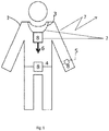
- the invention provides a personal emergency response device for providing an alarm 7 that is to be worn by a subject as a person 1.
- the device comprises a housing 8 with a neck cord 3 for placement of the device around the person's neck.
- the device can be arranged to be worn at or on a different part of the body such as the wrist or waist and will comprise a suitable arrangement for attaching the housing 8 to that part of the body (for example a belt 4 or a strap 5).
- the device is used for providing the alarm 7 at the request of the person 1, who has lost finger functionality due to stress or other reasons and cannot properly press the emergency push button.
- the invention provides an easy and convenient method for initiating the alarm 7 just by pulling the housing of the device with a pulling force 6 acting on housing as shown in Fig. 6 . For a person in distress it is easier to put his fingers around the housing, and pull it, than to search for a button somewhere on the housing of the device.
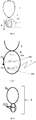
- Fig. 3 shows one of the possible embodiments of the device 2 in accordance with the invention.
- the device comprises a cord (or other attachment means for attaching the device to the body), a housing and a component having an electrical characteristic that depends on a force acting on it. In response to the pulling force 6 acting on the housing 8 a force is exerted on the component causing its electrical characteristic to change.
- the device may further comprise a circuit for detecting the change in the electronic characteristic and if it exceeds a predetermined threshold the alarm 7 is activated.
- the device may have a button 201 present on the housing to cancel an alarm that was accidently initiated.
- the device may comprise an accelerometer and the person may "shake" the device to revoke the alarm, the device being arranged to detect the "shaking" in response to data obtained with the accelerometer.
- the device may have an indicator to warn the person that the alarm was activated. The indicator may provide an audible, visual or tactile signal 202 and to give feedback to the person that the device is operational and has initiated the alarm.
- the component 301 is coupled to housing and may be situated as shown Fig 3 outside of the housing. Further the component is also coupled to the cord. When the person pulls the housing while it is attached to the body of the person a force will act on the component thereby changing the electrical characteristic. In another embodiment the component is included inside the housing as shown in Fig. 5 .
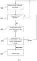
- the device operates according to the method shown in Fig. 2 which will now be explained in detail.
- Fig. 2 shows a block diagram illustrating an embodiment of the method of providing the alarm.
- the method of providing the alarm on request of a person wearing the device comprises the following steps:
- the change of the electrical characteristic may be compared with a threshold.
- the threshold is determined by a time filter.
- the device 2 when the detected change exceeds the threshold (e.g. is present sufficiently long or has a value sufficiently large) the device 2 will provide an audible, visual or tactile signal to the person 502.
- the threshold e.g. is present sufficiently long or has a value sufficiently large
- an additional condition is checked before an alarm will be initiated. If the person presses the revocation button 201 during a predetermined period after the signal is provided the alarm is revoked and the device will continue with detecting a potential change of the electrical characteristic (e.g a resistance of a stretch sensor or a voltage generated by a piezo electric component as will be explained in more detail later).
- a potential change of the electrical characteristic e.g a resistance of a stretch sensor or a voltage generated by a piezo electric component as will be explained in more detail later.
- the alarm is generated 504.
- the device itself also provides a further audible alarm to catch the attention of people close by.
- the alarm is wirelessly sent to an alarm control center as shown in Fig. 9 .
- the device 2 is coupled to a base unit 9.
- the device and base unit are included in a PERS system.
- the base unit 9 is arranged to act as a two -way hands free audio terminal. In case the person pulls the housing of the device to request for help the alarm is transferred to the base unit and from the base unit via internet, mobile or a landline to the alarm control center.
- Fig. 7 shows an embodiment of the component 301, 303 wherein the component is a mechanical switch 204 coupled to the cord 3 and to the housing.
- the component is a mechanical switch 204 coupled to the cord 3 and to the housing.
- a force is exerted on the mechanical switch causing it to be opened or closed.
- the pulling force may cause the mechanical switch to close which may be measured by an electronic circuit as shown in Fig. 7 .
- the electronic circuit for example may comprise a power supply, an ADC converter 205, a microcontroller 206, and a transmitter to send the alarm to the base unit.
- the component 301, 303 has a shape that changes in response to the pulling force, wherein the electrical characteristic is dependent on the shape or the change of the shape.
- Numerous sensors exist for measuring strain or elastic deformation of materials for example a stretch sensor, a strain gauge or a force/flex sensor. All of these sensors are based on the principle that stretching or compressing a conductive material causes its resistance to change. As the material is stretched its particles are spaced further apart, increasing the resistance. Conversely, as the material is compressed these particles are brought closer together resulting in a decrease in resistance or an increase in conductance.
- Elasticity is defined as the ability of a material to return to its original form or shape after a stress/force has been applied to it.
- the ease with which an elastic material will stretch is determined by a parameter known as the modulus, which defines the amount of stress or force per unit area to stretch the material.
- a low modulus means that the material is easy to stretch.
- a second important parameter is the elastic limit, or the minimum force for which the material ceases to be elastic, i.e. does not return to its original state.
- a neck cord includes a stretch sensor and conductive material to enable a measurement of the electrical characteristic of the component by a circuit in the device.
- the stretch sensor When the stretch sensor is stretched due to the person exerting a pulling force on the housing, the change of its electrical characteristic may be measured. Due to the modulus and elastic limit of the stretch sensor, care has to be taken to properly design the neck cord so that the sensor is not stretched beyond its elastic limit.
- the neck cord comprises the stretch sensor which is positioned inside a flexible tube 9.
- the advantage of this embodiment is that the tube prevents a stretching of the component beyond its elastic limit.
- the tube is less stretchable than the cord and has a predetermined length which limits the stretching of the stretch sensor beyond its elastic limit.
- the tube may be covering the cord and the component and be coupled to the housing, such that the conductive cord and the component are not visible.
- only the stretch sensor is inside the tube 9.
- the component comprises piezo elastic material.
- a pulling force acting on the housing causes a change in the shape of the component, which results in a change of the electrical characteristic of the piezo elastic material.
- a strip of piezo elastic material may provide a voltage in response to a bending of the strip, the amplitude of the voltage being dependent on the value of the pulling force.
- Fig. 8 shows yet a further embodiment of the device 2.
- the outside of the housing 8 is covered with two conductive elements 203 that are not in contact with each other, but that both will be touched by the hand of a person that grasps the housing to request for assistance.
- a further circuit included in the device measures the impedance between the conductive elements and in response to a measured impedance change the alarm is activated.
- the impedance change is only measured after a change in the electrical characteristic of the component has been measured and the alarm is only initiated when both changes have been detected.
- the device may contain a circuit to detect any changes in the electrical characteristic of the component.
- a circuit may for example comprise a voltage divider or a Wheatstone bridge, both known from prior art.
- the component may be a stretch sensor having a resistance. Stretching causes the resistance to change and this change may be measured using for example the voltage divider circuit.
- Fig. 10 shows the measuring circuit according to one embodiment of the circuit.
- Vout Rs Rs + R Vin , where Rs and R correspond to the sensor's resistance and reference resistance, respectively. Vin and Vout correspond to the supplied input voltage and measured output voltage, respectively. Therefore, as the sensor is stretched, the measured resistance Rs also increases and thus also Vout will increase.
- Ro denote the sensor's resistance when no force is applied
- the change in resistance is a linear function of the length increase x.
- Vout will increase, and thus the measured resistance Rs also increases.
- the measured value of Rs can also be averaged over time to attenuate the influence of sensor noise.
- either Vout or Rs can be used as a measure of stretch or force applied to the cord.
- measuring the stretch/strain gauge sensors resistance is achieved using a Wheatstone bridge which consists of two voltage divider circuits in parallel as shown in Fig. 11 .
- the sensitivity of the Wheatstone bridge is identical to the voltage divider.
- the Wheatstone bridge's output does not contain a large DC component due to taking the difference between the parallel voltage dividers and thus its output/sensitivity can be boosted by applying an amplifier.
- the measured resistance of the stretch sensor is used to detect a potential fall of the person.
- the measured resistance Rs When the measured resistance Rs is closer to Ro, it indicates that the person is in a supine position, since the weight of the pendant device does not exert a force on the stretch/strain gauge sensor, indicating that the person may have fallen. Alternatively when the measured resistance Rs is approximately equal to Ro this may be indicating that the person is not wearing the device.
- the component used is a stretch sensor or a strain gauge sensor and the device determines whether the person is in a supine position in dependence of a measured electrical characteristic of the stretch sensor.
- the device further comprises an accelerometer. If the low value for Rs was preceded by an impact measured by an accelerometer, it is highly probably that the person has fallen.
- the system may interpret this as the user pulling on the housing device to signal for help.
Landscapes
- Business, Economics & Management (AREA)
- Emergency Management (AREA)
- Physics & Mathematics (AREA)
- General Physics & Mathematics (AREA)
- Engineering & Computer Science (AREA)
- Computer Security & Cryptography (AREA)
- Alarm Systems (AREA)
- Emergency Alarm Devices (AREA)
Claims (11)
- Dispositif d'intervention d'urgence personnel portable (2) pour fournir une alarme à la demande d'une personne (1) portant le dispositif, le dispositif comprenant:- un boîtier (8);- une sangle (5) couplée au boîtier pour porter, lors de l'utilisation, le dispositif fixé au poignet, une ceinture (4) couplée au boîtier pour porter, lors de l'utilisation, le dispositif fixé à la taille, ou un cordon (3) couplé au boîtier pour porter le dispositif autour du cou;où
le dispositif comprend en outre un composant (301, 303) ayant une caractéristique électrique, le boîtier est en outre couplé au composant, la caractéristique électrique étant modifiable en réponse à une force de traction (6) de la personne (1) agissant sur le boîtier; et où l'extérieur du boîtier (8) comprend des éléments conducteurs (203); le dispositif étant agencé pour mesurer une impédance entre les éléments conducteurs; et où l'alarme (7) est activée uniquement lorsque à la fois une modification de la caractéristique électrique du composant (301, 303) et une modification de l'impédance entre les éléments conducteurs (203) à l'extérieur du boîtier (8) ont été mesurées qui sont causées par la personne qui saisit le boîtier. - Dispositif (2) selon la revendication 1, dans lequel le composant (301) est un interrupteur mécanique (204) qui est en outre couplé à la sangle (5), à la ceinture (4) ou au cordon (3), où, lors de l'utilisation, l'interrupteur mécanique est fermé ou ouvert en fonction de la force de traction (6) agissant sur le boîtier (8).
- Dispositif (2) selon la revendication 1, dans lequel le composant (301, 303) a une forme qui est modifiable en réponse à la force de traction (6) agissant sur le boîtier (8) où la caractéristique électrique dépend de la forme.
- Dispositif (2) selon la revendication 1, dans lequel le composant (301) comprend un matériau élastique.
- Dispositif selon la revendication 4, dans lequel le matériau élastique comprend un matériau piézoélastique ou un extensomètre (303).
- Dispositif (2) selon la revendication 3, 4 ou 5, dans lequel le composant est couplé via la sangle (5), la ceinture (4) ou le cordon (3) au boîtier (8); la sangle, la ceinture ou le cordon comprenant en outre un matériau conducteur pour fournir une connexion électrique au composant pour permettre la mesure d'un changement de la caractéristique électrique.
- Dispositif (2) selon la revendication 6 dans lequel le composant est positionné à l'intérieur d'un tube (9), le tube étant souple et moins extensible que le composant; le tube étant couplé au boîtier (8) et ayant une longueur prédéterminée limitant l'étirement du composant, lors de l'utilisation la force de traction (6) agit sur le boîtier.
- Dispositif (2) selon l'une quelconque des revendications 1 à 7, comprenant en outre un filtre temporel pour supprimer l'alarme lorsque la force de traction (6) agissant sur le boîtier (8) est plus courte qu'une période de temps prédéterminée.
- Dispositif (2) selon l'une quelconque des revendications 1 à 8, comprenant une interface utilisateur (201) pour révoquer l'alarme et le dispositif est en outre agencé pour fournir un signal sonore, visuel ou tactile (202) en réponse à un activation de l'alarme (7).
- Dispositif selon la revendication 1, dans lequel le composant est un capteur d'étirement et dans lequel le dispositif est agencé pour fournir une indication d'une chute potentielle de la personne en réponse à une caractéristique électrique mesurée du capteur d'étirement.
- Système d'intervention d'urgence personnel comprenant le dispositif (2) selon l'une quelconque des revendications 1 à 10 et une unité de base (9), dans lequel le dispositif est couplé à l'unité de base (9) qui est de préférence agencée pour agir comme un terminal audio mains libres bidirectionnel, l'unité de base étant couplée à un centre de commande d'alarme pour transférer l'alarme (7) reçue du dispositif vers un centre de commande d'alarme (10).
Applications Claiming Priority (2)
| Application Number | Priority Date | Filing Date | Title |
|---|---|---|---|
| EP14199734 | 2014-12-22 | ||
| PCT/EP2015/080485 WO2016102363A1 (fr) | 2014-12-22 | 2015-12-18 | Procédé et dispositif de fourniture d'alarme |
Publications (2)
| Publication Number | Publication Date |
|---|---|
| EP3238192A1 EP3238192A1 (fr) | 2017-11-01 |
| EP3238192B1 true EP3238192B1 (fr) | 2021-02-17 |
Family
ID=52144533
Family Applications (1)
| Application Number | Title | Priority Date | Filing Date |
|---|---|---|---|
| EP15813071.6A Active EP3238192B1 (fr) | 2014-12-22 | 2015-12-18 | Procédé et dispositif destinés à fournir une alarme |
Country Status (6)
| Country | Link |
|---|---|
| US (1) | US9984548B2 (fr) |
| EP (1) | EP3238192B1 (fr) |
| JP (1) | JP6665186B2 (fr) |
| CN (1) | CN107111924B (fr) |
| RU (1) | RU2664948C1 (fr) |
| WO (1) | WO2016102363A1 (fr) |
Families Citing this family (7)
| Publication number | Priority date | Publication date | Assignee | Title |
|---|---|---|---|---|
| WO2017140537A1 (fr) * | 2016-02-16 | 2017-08-24 | Koninklijke Philips N.V. | Dispositif de cordon, procédé et système de surveillance de cordon personnel |
| US10163282B2 (en) * | 2016-03-30 | 2018-12-25 | Intermec, Inc. | Systems and methods for authentication |
| US10637995B2 (en) * | 2016-10-27 | 2020-04-28 | Russell M. Hanabusa | Remote alert generation based on trigger events indicating attack |
| EP3667635A1 (fr) | 2018-12-14 | 2020-06-17 | Koninklijke Philips N.V. | Dispositif de détection d'urgence porté au poignet |
| US10515529B1 (en) * | 2019-01-22 | 2019-12-24 | Timothy Taylor | Energized circuit alarm assembly |
| CN111462431A (zh) * | 2020-05-22 | 2020-07-28 | 中国联合网络通信集团有限公司 | 智能音箱 |
| US20220401017A1 (en) * | 2021-06-22 | 2022-12-22 | Hangzhou Zhixing Technology Co., Ltd. | Posture detection device and necklace |
Family Cites Families (48)
| Publication number | Priority date | Publication date | Assignee | Title |
|---|---|---|---|---|
| US3701140A (en) * | 1971-03-05 | 1972-10-24 | Richard W Dixon | Purse theft alarm |
| US4170897A (en) * | 1977-04-22 | 1979-10-16 | Babcock Clarence O | Displacement measuring sensor |
| US4281237A (en) * | 1979-03-05 | 1981-07-28 | Sunbeam Corporation | Safety circuit for electric bedcover |
| JPH01138824A (ja) * | 1987-11-26 | 1989-05-31 | Matsushita Electric Works Ltd | 携帯用ワイヤレス発信器 |
| US4952928A (en) * | 1988-08-29 | 1990-08-28 | B. I. Incorporated | Adaptable electronic monitoring and identification system |
| US5295490A (en) * | 1993-01-21 | 1994-03-22 | Dodakian Wayne S | Self-contained apnea monitor |
| JP3477894B2 (ja) * | 1995-02-28 | 2003-12-10 | 松下電工株式会社 | 非常呼出器、及びこれを用いた非常連絡システム、ワイヤレス紐付き救急発信器 |
| US5666961A (en) * | 1995-06-20 | 1997-09-16 | Mcfarlin, Sr.; Bill E. | Expansion indicator device |
| US5656996A (en) | 1996-03-13 | 1997-08-12 | Global Associates, Ltd. | Electronic security bonding device |
| JPH11215063A (ja) * | 1998-01-21 | 1999-08-06 | Atsuden Kk | ワイヤレスマイクロホン |
| AU5359901A (en) * | 2000-04-17 | 2001-10-30 | Vivometrics Inc | Systems and methods for ambulatory monitoring of physiological signs |
| US7304580B2 (en) * | 2003-12-04 | 2007-12-04 | Hoana Medical, Inc. | Intelligent medical vigilance system |
| JP2002140776A (ja) * | 2000-11-01 | 2002-05-17 | Matsushita Electric Ind Co Ltd | 人体状態検出装置及び人体状態確認システム |
| US6561987B2 (en) * | 2001-03-02 | 2003-05-13 | Opher Pail | Apparatus and methods for indicating respiratory phases to improve speech/breathing synchronization |
| AUPS264302A0 (en) * | 2002-05-29 | 2002-06-20 | Neopraxis Pty Ltd | Implantable bladder sensor |
| US7020508B2 (en) * | 2002-08-22 | 2006-03-28 | Bodymedia, Inc. | Apparatus for detecting human physiological and contextual information |
| US20040080421A1 (en) * | 2002-10-16 | 2004-04-29 | Wunderlich Neila Johnilynn | Monitoring and alert system |
| US7150048B2 (en) | 2002-12-18 | 2006-12-19 | Buckman Robert F | Method and apparatus for body impact protection |
| JP2004221943A (ja) * | 2003-01-15 | 2004-08-05 | Nikon Corp | ストラップを備えたカメラおよび機器 |
| FR2858758B1 (fr) * | 2003-08-14 | 2006-04-07 | Tam Telesante Sarl | Systeme de surveillance medicale au moyen d'un vetement |
| FI116809B (fi) * | 2004-07-06 | 2006-02-28 | Ist Oy | Turvalaitejärjestelmä |
| WO2006034291A2 (fr) * | 2004-09-21 | 2006-03-30 | Vivometrics, Inc. | Capteurs perfectionnes pour applications de controle en plethysmographie inductive et appareil utilisant ces capteurs |
| CA2486949A1 (fr) * | 2004-12-09 | 2006-06-09 | Christian Cloutier | Systeme et methode pour la detection des chutes et du suivi des niveaux d'activite a distance chez des personnes en perte d'autonomie |
| US7733224B2 (en) | 2006-06-30 | 2010-06-08 | Bao Tran | Mesh network personal emergency response appliance |
| JP2007213533A (ja) * | 2006-02-08 | 2007-08-23 | Jupiter Net:Kk | 超小型携帯型緊急通報装置 |
| US7712373B2 (en) * | 2006-03-03 | 2010-05-11 | Nagle H Troy | Sensor device for real-time monitoring or relative movement using capacitive fabric sensors |
| US7494004B2 (en) * | 2006-06-23 | 2009-02-24 | Siemens Energy & Automation, Inc. | Method and apparatus for monitoring conveyor belts |
| US8175590B2 (en) * | 2007-09-26 | 2012-05-08 | Stryker Corporation | System for preventing unintended activation of a medical device by a portable remote control console |
| US20090121863A1 (en) | 2007-11-13 | 2009-05-14 | Rich Prior | Medical safety monitor system |
| US8373565B2 (en) | 2008-02-22 | 2013-02-12 | Xiao Hui Yang | Security apparatus with conductive ribbons |
| BRPI0913494A2 (pt) | 2008-09-12 | 2016-07-26 | Koninkl Philips Electronics Nv | sistema de detecção de queda e método de operação de um sistema de detecção de queda |
| US9342971B2 (en) * | 2008-12-15 | 2016-05-17 | Robert Bosch Gmbh | Duress alarm system for clothing |
| CN102469956B (zh) | 2009-07-22 | 2014-09-24 | 皇家飞利浦电子股份有限公司 | 跌倒检测器和检测跌倒的方法 |
| WO2011013026A1 (fr) | 2009-07-28 | 2011-02-03 | Koninklijke Philips Electronics N.V. | Tour de cou et système émetteur d'appel d'urgence personnel |
| US9211085B2 (en) * | 2010-05-03 | 2015-12-15 | Foster-Miller, Inc. | Respiration sensing system |
| JP2010231823A (ja) * | 2010-07-20 | 2010-10-14 | Tokyo Gas Co Ltd | 警報器 |
| US9937355B2 (en) * | 2010-11-08 | 2018-04-10 | Zoll Medical Corporation | Remote medical device alarm |
| JP5998202B2 (ja) | 2011-04-29 | 2016-09-28 | コーニンクレッカ フィリップス エヌ ヴェKoninklijke Philips N.V. | 転倒検出器又は転倒検出システムに用いられる装置及びこれを操作する方法 |
| EP2549228A1 (fr) | 2011-07-20 | 2013-01-23 | Koninklijke Philips Electronics N.V. | Procédé d'amélioration de la détectabilité d'un changement de hauteur avec un capteur de pression d'air et unité de capteur permettant de déterminer un changement de hauteur |
| US20130021154A1 (en) * | 2011-07-21 | 2013-01-24 | Solomon Clifford T | Medical parameters notification system |
| US9098991B2 (en) * | 2013-01-15 | 2015-08-04 | Fitbit, Inc. | Portable monitoring devices and methods of operating the same |
| US20140276238A1 (en) | 2013-03-15 | 2014-09-18 | Ivan Osorio | Method, system and apparatus for fall detection |
| US9153115B1 (en) * | 2013-03-28 | 2015-10-06 | Eric Ulner | Fall impact signal transmitter |
| TWM464778U (zh) * | 2013-05-29 | 2013-11-01 | Fu-Cheng Xu | 個人防身求救設備改良 |
| US20150064675A1 (en) * | 2013-08-30 | 2015-03-05 | 7-Sigma, Inc. | Responsive tool with sensors |
| ES2663028T3 (es) * | 2013-10-16 | 2018-04-10 | Koninklijke Philips N.V. | Un dispositivo de conversión de un movimiento de un usuario en una tensión |
| KR102169952B1 (ko) * | 2013-10-18 | 2020-10-26 | 엘지전자 주식회사 | 웨어러블 디바이스 및 그 제어 방법 |
| EP3227730A4 (fr) * | 2014-12-03 | 2018-08-01 | University Of British Columbia | Capteur transparent souple à matériau ioniquement conducteur |
-
2015
- 2015-12-18 US US15/538,933 patent/US9984548B2/en active Active
- 2015-12-18 EP EP15813071.6A patent/EP3238192B1/fr active Active
- 2015-12-18 WO PCT/EP2015/080485 patent/WO2016102363A1/fr active Application Filing
- 2015-12-18 RU RU2017126239A patent/RU2664948C1/ru active
- 2015-12-18 JP JP2017533462A patent/JP6665186B2/ja not_active Expired - Fee Related
- 2015-12-18 CN CN201580070175.2A patent/CN107111924B/zh not_active Expired - Fee Related
Non-Patent Citations (1)
| Title |
|---|
| None * |
Also Published As
| Publication number | Publication date |
|---|---|
| JP6665186B2 (ja) | 2020-03-13 |
| US9984548B2 (en) | 2018-05-29 |
| WO2016102363A1 (fr) | 2016-06-30 |
| US20170358191A1 (en) | 2017-12-14 |
| EP3238192A1 (fr) | 2017-11-01 |
| RU2664948C1 (ru) | 2018-08-23 |
| CN107111924B (zh) | 2019-11-26 |
| JP2018501577A (ja) | 2018-01-18 |
| CN107111924A (zh) | 2017-08-29 |
Similar Documents
| Publication | Publication Date | Title |
|---|---|---|
| EP3238192B1 (fr) | Procédé et dispositif destinés à fournir une alarme | |
| US7319400B2 (en) | Method and apparatus for monitoring a restraint device | |
| US8106781B2 (en) | Device for monitoring the condition of a human being | |
| JP5210264B2 (ja) | 生体情報を収集し伝達する装置 | |
| EP3084656B1 (fr) | Procédé pour répondre à une chute détectée et un appareil pour la mise en oeuvre de la même | |
| JP6281290B2 (ja) | リストバンド型腕動作判定装置 | |
| US20120268268A1 (en) | Mobile sensory device | |
| US9750456B2 (en) | Method and system of attachment and detection of attachment of a wearable sensor to clothing material | |
| WO2010044013A1 (fr) | Système de détection de chute | |
| WO2015069946A2 (fr) | Stockage d'informations sélectivement disponibles et système de communication | |
| JP2014202744A (ja) | 歩行検出装置及び歩行検出用送信機 | |
| US20190350462A1 (en) | Methods and devices for measuring body temperature in a reduced time | |
| JP2019528106A5 (fr) | ||
| EP2900128B1 (fr) | Compteur d'impulsions pour nouveaux-nés | |
| JP2018501577A5 (fr) | ||
| KR20180054384A (ko) | 위급환자 발생 감지용 스마트밴드 시스템을 이용한 위급환자정보 제공방법 | |
| US10182761B2 (en) | Method and system of attachment and detection of attachment of a wearable sensor to clothing material | |
| Silverio et al. | Low-cost elderly healthcare monitoring system | |
| KR20180075211A (ko) | 사용자 신체에 부착 가능한 스마트 패치를 이용한 건강 모니터링 방법 | |
| CN113168755A (zh) | 用于监测用户的方法和系统 | |
| KR20180065118A (ko) | 응급 대응 기기 | |
| WO2018068068A2 (fr) | Dispositif de surveillance | |
| JPS63275319A (ja) | 急病自動監視装置 | |
| SE513473C2 (sv) | Larmssystem för övervakning av personer såsom sängliggande patienter |
Legal Events
| Date | Code | Title | Description |
|---|---|---|---|
| STAA | Information on the status of an ep patent application or granted ep patent |
Free format text: STATUS: THE INTERNATIONAL PUBLICATION HAS BEEN MADE |
|
| PUAI | Public reference made under article 153(3) epc to a published international application that has entered the european phase |
Free format text: ORIGINAL CODE: 0009012 |
|
| STAA | Information on the status of an ep patent application or granted ep patent |
Free format text: STATUS: REQUEST FOR EXAMINATION WAS MADE |
|
| 17P | Request for examination filed |
Effective date: 20170724 |
|
| AK | Designated contracting states |
Kind code of ref document: A1 Designated state(s): AL AT BE BG CH CY CZ DE DK EE ES FI FR GB GR HR HU IE IS IT LI LT LU LV MC MK MT NL NO PL PT RO RS SE SI SK SM TR |
|
| AX | Request for extension of the european patent |
Extension state: BA ME |
|
| DAV | Request for validation of the european patent (deleted) | ||
| DAX | Request for extension of the european patent (deleted) | ||
| STAA | Information on the status of an ep patent application or granted ep patent |
Free format text: STATUS: EXAMINATION IS IN PROGRESS |
|
| 17Q | First examination report despatched |
Effective date: 20191015 |
|
| RAP1 | Party data changed (applicant data changed or rights of an application transferred) |
Owner name: KONINKLIJKE PHILIPS N.V. |
|
| GRAP | Despatch of communication of intention to grant a patent |
Free format text: ORIGINAL CODE: EPIDOSNIGR1 |
|
| STAA | Information on the status of an ep patent application or granted ep patent |
Free format text: STATUS: GRANT OF PATENT IS INTENDED |
|
| INTG | Intention to grant announced |
Effective date: 20200902 |
|
| GRAS | Grant fee paid |
Free format text: ORIGINAL CODE: EPIDOSNIGR3 |
|
| GRAA | (expected) grant |
Free format text: ORIGINAL CODE: 0009210 |
|
| STAA | Information on the status of an ep patent application or granted ep patent |
Free format text: STATUS: THE PATENT HAS BEEN GRANTED |
|
| AK | Designated contracting states |
Kind code of ref document: B1 Designated state(s): AL AT BE BG CH CY CZ DE DK EE ES FI FR GB GR HR HU IE IS IT LI LT LU LV MC MK MT NL NO PL PT RO RS SE SI SK SM TR |
|
| REG | Reference to a national code |
Ref country code: GB Ref legal event code: FG4D |
|
| REG | Reference to a national code |
Ref country code: CH Ref legal event code: EP |
|
| REG | Reference to a national code |
Ref country code: DE Ref legal event code: R096 Ref document number: 602015065707 Country of ref document: DE |
|
| REG | Reference to a national code |
Ref country code: AT Ref legal event code: REF Ref document number: 1362498 Country of ref document: AT Kind code of ref document: T Effective date: 20210315 |
|
| REG | Reference to a national code |
Ref country code: IE Ref legal event code: FG4D |
|
| REG | Reference to a national code |
Ref country code: LT Ref legal event code: MG9D |
|
| REG | Reference to a national code |
Ref country code: NL Ref legal event code: MP Effective date: 20210217 |
|
| PG25 | Lapsed in a contracting state [announced via postgrant information from national office to epo] |
Ref country code: PT Free format text: LAPSE BECAUSE OF FAILURE TO SUBMIT A TRANSLATION OF THE DESCRIPTION OR TO PAY THE FEE WITHIN THE PRESCRIBED TIME-LIMIT Effective date: 20210617 Ref country code: NO Free format text: LAPSE BECAUSE OF FAILURE TO SUBMIT A TRANSLATION OF THE DESCRIPTION OR TO PAY THE FEE WITHIN THE PRESCRIBED TIME-LIMIT Effective date: 20210517 Ref country code: LT Free format text: LAPSE BECAUSE OF FAILURE TO SUBMIT A TRANSLATION OF THE DESCRIPTION OR TO PAY THE FEE WITHIN THE PRESCRIBED TIME-LIMIT Effective date: 20210217 Ref country code: GR Free format text: LAPSE BECAUSE OF FAILURE TO SUBMIT A TRANSLATION OF THE DESCRIPTION OR TO PAY THE FEE WITHIN THE PRESCRIBED TIME-LIMIT Effective date: 20210518 Ref country code: HR Free format text: LAPSE BECAUSE OF FAILURE TO SUBMIT A TRANSLATION OF THE DESCRIPTION OR TO PAY THE FEE WITHIN THE PRESCRIBED TIME-LIMIT Effective date: 20210217 Ref country code: FI Free format text: LAPSE BECAUSE OF FAILURE TO SUBMIT A TRANSLATION OF THE DESCRIPTION OR TO PAY THE FEE WITHIN THE PRESCRIBED TIME-LIMIT Effective date: 20210217 Ref country code: BG Free format text: LAPSE BECAUSE OF FAILURE TO SUBMIT A TRANSLATION OF THE DESCRIPTION OR TO PAY THE FEE WITHIN THE PRESCRIBED TIME-LIMIT Effective date: 20210517 |
|
| REG | Reference to a national code |
Ref country code: AT Ref legal event code: MK05 Ref document number: 1362498 Country of ref document: AT Kind code of ref document: T Effective date: 20210217 |
|
| PG25 | Lapsed in a contracting state [announced via postgrant information from national office to epo] |
Ref country code: SE Free format text: LAPSE BECAUSE OF FAILURE TO SUBMIT A TRANSLATION OF THE DESCRIPTION OR TO PAY THE FEE WITHIN THE PRESCRIBED TIME-LIMIT Effective date: 20210217 Ref country code: LV Free format text: LAPSE BECAUSE OF FAILURE TO SUBMIT A TRANSLATION OF THE DESCRIPTION OR TO PAY THE FEE WITHIN THE PRESCRIBED TIME-LIMIT Effective date: 20210217 Ref country code: PL Free format text: LAPSE BECAUSE OF FAILURE TO SUBMIT A TRANSLATION OF THE DESCRIPTION OR TO PAY THE FEE WITHIN THE PRESCRIBED TIME-LIMIT Effective date: 20210217 Ref country code: RS Free format text: LAPSE BECAUSE OF FAILURE TO SUBMIT A TRANSLATION OF THE DESCRIPTION OR TO PAY THE FEE WITHIN THE PRESCRIBED TIME-LIMIT Effective date: 20210217 Ref country code: NL Free format text: LAPSE BECAUSE OF FAILURE TO SUBMIT A TRANSLATION OF THE DESCRIPTION OR TO PAY THE FEE WITHIN THE PRESCRIBED TIME-LIMIT Effective date: 20210217 |
|
| PG25 | Lapsed in a contracting state [announced via postgrant information from national office to epo] |
Ref country code: IS Free format text: LAPSE BECAUSE OF FAILURE TO SUBMIT A TRANSLATION OF THE DESCRIPTION OR TO PAY THE FEE WITHIN THE PRESCRIBED TIME-LIMIT Effective date: 20210617 |
|
| RAP2 | Party data changed (patent owner data changed or rights of a patent transferred) |
Owner name: LIFELINE SYSTEMS COMPANY |
|
| PG25 | Lapsed in a contracting state [announced via postgrant information from national office to epo] |
Ref country code: SM Free format text: LAPSE BECAUSE OF FAILURE TO SUBMIT A TRANSLATION OF THE DESCRIPTION OR TO PAY THE FEE WITHIN THE PRESCRIBED TIME-LIMIT Effective date: 20210217 Ref country code: AT Free format text: LAPSE BECAUSE OF FAILURE TO SUBMIT A TRANSLATION OF THE DESCRIPTION OR TO PAY THE FEE WITHIN THE PRESCRIBED TIME-LIMIT Effective date: 20210217 Ref country code: EE Free format text: LAPSE BECAUSE OF FAILURE TO SUBMIT A TRANSLATION OF THE DESCRIPTION OR TO PAY THE FEE WITHIN THE PRESCRIBED TIME-LIMIT Effective date: 20210217 Ref country code: CZ Free format text: LAPSE BECAUSE OF FAILURE TO SUBMIT A TRANSLATION OF THE DESCRIPTION OR TO PAY THE FEE WITHIN THE PRESCRIBED TIME-LIMIT Effective date: 20210217 |
|
| REG | Reference to a national code |
Ref country code: DE Ref legal event code: R081 Ref document number: 602015065707 Country of ref document: DE Owner name: LIFELINE SYSTEMS COMPANY, FRAMINGHAM, US Free format text: FORMER OWNER: KONINKLIJKE PHILIPS N.V., EINDHOVEN, NL Ref country code: DE Ref legal event code: R082 Ref document number: 602015065707 Country of ref document: DE Representative=s name: HL KEMPNER PATENTANWAELTE, SOLICITORS (ENGLAND, DE Ref country code: DE Ref legal event code: R082 Ref document number: 602015065707 Country of ref document: DE Representative=s name: HL KEMPNER PATENTANWALT, RECHTSANWALT, SOLICIT, DE Ref document number: 602015065707 Country of ref document: DE |
|
| REG | Reference to a national code |
Ref country code: DE Ref legal event code: R097 Ref document number: 602015065707 Country of ref document: DE |
|
| REG | Reference to a national code |
Ref country code: DE Ref legal event code: R082 Ref document number: 602015065707 Country of ref document: DE Representative=s name: HL KEMPNER PATENTANWALT, RECHTSANWALT, SOLICIT, DE Ref country code: DE Ref legal event code: R082 Ref document number: 602015065707 Country of ref document: DE Representative=s name: HL KEMPNER PATENTANWAELTE, SOLICITORS (ENGLAND, DE |
|
| PG25 | Lapsed in a contracting state [announced via postgrant information from national office to epo] |
Ref country code: SK Free format text: LAPSE BECAUSE OF FAILURE TO SUBMIT A TRANSLATION OF THE DESCRIPTION OR TO PAY THE FEE WITHIN THE PRESCRIBED TIME-LIMIT Effective date: 20210217 Ref country code: RO Free format text: LAPSE BECAUSE OF FAILURE TO SUBMIT A TRANSLATION OF THE DESCRIPTION OR TO PAY THE FEE WITHIN THE PRESCRIBED TIME-LIMIT Effective date: 20210217 Ref country code: DK Free format text: LAPSE BECAUSE OF FAILURE TO SUBMIT A TRANSLATION OF THE DESCRIPTION OR TO PAY THE FEE WITHIN THE PRESCRIBED TIME-LIMIT Effective date: 20210217 |
|
| PLBE | No opposition filed within time limit |
Free format text: ORIGINAL CODE: 0009261 |
|
| STAA | Information on the status of an ep patent application or granted ep patent |
Free format text: STATUS: NO OPPOSITION FILED WITHIN TIME LIMIT |
|
| REG | Reference to a national code |
Ref country code: GB Ref legal event code: 732E Free format text: REGISTERED BETWEEN 20211202 AND 20211209 |
|
| 26N | No opposition filed |
Effective date: 20211118 |
|
| PG25 | Lapsed in a contracting state [announced via postgrant information from national office to epo] |
Ref country code: AL Free format text: LAPSE BECAUSE OF FAILURE TO SUBMIT A TRANSLATION OF THE DESCRIPTION OR TO PAY THE FEE WITHIN THE PRESCRIBED TIME-LIMIT Effective date: 20210217 Ref country code: ES Free format text: LAPSE BECAUSE OF FAILURE TO SUBMIT A TRANSLATION OF THE DESCRIPTION OR TO PAY THE FEE WITHIN THE PRESCRIBED TIME-LIMIT Effective date: 20210217 |
|
| PGFP | Annual fee paid to national office [announced via postgrant information from national office to epo] |
Ref country code: GB Payment date: 20211028 Year of fee payment: 7 Ref country code: DE Payment date: 20211027 Year of fee payment: 7 |
|
| PG25 | Lapsed in a contracting state [announced via postgrant information from national office to epo] |
Ref country code: SI Free format text: LAPSE BECAUSE OF FAILURE TO SUBMIT A TRANSLATION OF THE DESCRIPTION OR TO PAY THE FEE WITHIN THE PRESCRIBED TIME-LIMIT Effective date: 20210217 |
|
| PG25 | Lapsed in a contracting state [announced via postgrant information from national office to epo] |
Ref country code: IT Free format text: LAPSE BECAUSE OF FAILURE TO SUBMIT A TRANSLATION OF THE DESCRIPTION OR TO PAY THE FEE WITHIN THE PRESCRIBED TIME-LIMIT Effective date: 20210217 |
|
| PG25 | Lapsed in a contracting state [announced via postgrant information from national office to epo] |
Ref country code: IS Free format text: LAPSE BECAUSE OF FAILURE TO SUBMIT A TRANSLATION OF THE DESCRIPTION OR TO PAY THE FEE WITHIN THE PRESCRIBED TIME-LIMIT Effective date: 20210617 |
|
| PG25 | Lapsed in a contracting state [announced via postgrant information from national office to epo] |
Ref country code: MC Free format text: LAPSE BECAUSE OF FAILURE TO SUBMIT A TRANSLATION OF THE DESCRIPTION OR TO PAY THE FEE WITHIN THE PRESCRIBED TIME-LIMIT Effective date: 20210217 |
|
| REG | Reference to a national code |
Ref country code: CH Ref legal event code: PL |
|
| REG | Reference to a national code |
Ref country code: BE Ref legal event code: MM Effective date: 20211231 |
|
| PG25 | Lapsed in a contracting state [announced via postgrant information from national office to epo] |
Ref country code: LU Free format text: LAPSE BECAUSE OF NON-PAYMENT OF DUE FEES Effective date: 20211218 Ref country code: IE Free format text: LAPSE BECAUSE OF NON-PAYMENT OF DUE FEES Effective date: 20211218 |
|
| PG25 | Lapsed in a contracting state [announced via postgrant information from national office to epo] |
Ref country code: FR Free format text: LAPSE BECAUSE OF NON-PAYMENT OF DUE FEES Effective date: 20211231 Ref country code: BE Free format text: LAPSE BECAUSE OF NON-PAYMENT OF DUE FEES Effective date: 20211231 |
|
| PG25 | Lapsed in a contracting state [announced via postgrant information from national office to epo] |
Ref country code: LI Free format text: LAPSE BECAUSE OF NON-PAYMENT OF DUE FEES Effective date: 20211231 Ref country code: CH Free format text: LAPSE BECAUSE OF NON-PAYMENT OF DUE FEES Effective date: 20211231 |
|
| PG25 | Lapsed in a contracting state [announced via postgrant information from national office to epo] |
Ref country code: HU Free format text: LAPSE BECAUSE OF FAILURE TO SUBMIT A TRANSLATION OF THE DESCRIPTION OR TO PAY THE FEE WITHIN THE PRESCRIBED TIME-LIMIT; INVALID AB INITIO Effective date: 20151218 |
|
| PG25 | Lapsed in a contracting state [announced via postgrant information from national office to epo] |
Ref country code: CY Free format text: LAPSE BECAUSE OF FAILURE TO SUBMIT A TRANSLATION OF THE DESCRIPTION OR TO PAY THE FEE WITHIN THE PRESCRIBED TIME-LIMIT Effective date: 20210217 |
|
| REG | Reference to a national code |
Ref country code: DE Ref legal event code: R119 Ref document number: 602015065707 Country of ref document: DE |
|
| GBPC | Gb: european patent ceased through non-payment of renewal fee |
Effective date: 20221218 |
|
| PG25 | Lapsed in a contracting state [announced via postgrant information from national office to epo] |
Ref country code: GB Free format text: LAPSE BECAUSE OF NON-PAYMENT OF DUE FEES Effective date: 20221218 Ref country code: DE Free format text: LAPSE BECAUSE OF NON-PAYMENT OF DUE FEES Effective date: 20230701 |
|
| PG25 | Lapsed in a contracting state [announced via postgrant information from national office to epo] |
Ref country code: MK Free format text: LAPSE BECAUSE OF FAILURE TO SUBMIT A TRANSLATION OF THE DESCRIPTION OR TO PAY THE FEE WITHIN THE PRESCRIBED TIME-LIMIT Effective date: 20210217 |
|
| PG25 | Lapsed in a contracting state [announced via postgrant information from national office to epo] |
Ref country code: MT Free format text: LAPSE BECAUSE OF FAILURE TO SUBMIT A TRANSLATION OF THE DESCRIPTION OR TO PAY THE FEE WITHIN THE PRESCRIBED TIME-LIMIT Effective date: 20210217 |