EP3237745B1 - Device for feeding for the conveying and for heating a medium - Google Patents
Device for feeding for the conveying and for heating a medium Download PDFInfo
- Publication number
- EP3237745B1 EP3237745B1 EP15816431.9A EP15816431A EP3237745B1 EP 3237745 B1 EP3237745 B1 EP 3237745B1 EP 15816431 A EP15816431 A EP 15816431A EP 3237745 B1 EP3237745 B1 EP 3237745B1
- Authority
- EP
- European Patent Office
- Prior art keywords
- electric motor
- medium
- control unit
- alternating current
- conductor winding
- Prior art date
- Legal status (The legal status is an assumption and is not a legal conclusion. Google has not performed a legal analysis and makes no representation as to the accuracy of the status listed.)
- Active
Links
- 238000010438 heat treatment Methods 0.000 title claims description 27
- 238000004804 winding Methods 0.000 claims description 55
- 239000004020 conductor Substances 0.000 claims description 50
- 238000000034 method Methods 0.000 claims description 21
- 239000000446 fuel Substances 0.000 claims description 12
- XSQUKJJJFZCRTK-UHFFFAOYSA-N Urea Chemical compound NC(N)=O XSQUKJJJFZCRTK-UHFFFAOYSA-N 0.000 claims description 8
- 239000004202 carbamide Substances 0.000 claims description 8
- 238000002485 combustion reaction Methods 0.000 claims description 5
- XEEYBQQBJWHFJM-UHFFFAOYSA-N Iron Chemical compound [Fe] XEEYBQQBJWHFJM-UHFFFAOYSA-N 0.000 description 10
- 238000005086 pumping Methods 0.000 description 6
- 239000002283 diesel fuel Substances 0.000 description 5
- 229910052742 iron Inorganic materials 0.000 description 5
- 238000004590 computer program Methods 0.000 description 3
- 230000001419 dependent effect Effects 0.000 description 3
- 238000006073 displacement reaction Methods 0.000 description 3
- 238000007711 solidification Methods 0.000 description 3
- 230000008023 solidification Effects 0.000 description 3
- 230000000694 effects Effects 0.000 description 2
- 239000002828 fuel tank Substances 0.000 description 2
- 230000007246 mechanism Effects 0.000 description 2
- 230000005540 biological transmission Effects 0.000 description 1
- 238000010276 construction Methods 0.000 description 1
- 238000011161 development Methods 0.000 description 1
- 230000018109 developmental process Effects 0.000 description 1
- 238000003475 lamination Methods 0.000 description 1
- 239000007788 liquid Substances 0.000 description 1
- 239000000696 magnetic material Substances 0.000 description 1
- 230000002195 synergetic effect Effects 0.000 description 1
- 230000001960 triggered effect Effects 0.000 description 1
- XLYOFNOQVPJJNP-UHFFFAOYSA-N water Substances O XLYOFNOQVPJJNP-UHFFFAOYSA-N 0.000 description 1
Images

Classifications
-
- F—MECHANICAL ENGINEERING; LIGHTING; HEATING; WEAPONS; BLASTING
- F02—COMBUSTION ENGINES; HOT-GAS OR COMBUSTION-PRODUCT ENGINE PLANTS
- F02M—SUPPLYING COMBUSTION ENGINES IN GENERAL WITH COMBUSTIBLE MIXTURES OR CONSTITUENTS THEREOF
- F02M37/00—Apparatus or systems for feeding liquid fuel from storage containers to carburettors or fuel-injection apparatus; Arrangements for purifying liquid fuel specially adapted for, or arranged on, internal-combustion engines
- F02M37/04—Feeding by means of driven pumps
- F02M37/08—Feeding by means of driven pumps electrically driven
-
- F—MECHANICAL ENGINEERING; LIGHTING; HEATING; WEAPONS; BLASTING
- F01—MACHINES OR ENGINES IN GENERAL; ENGINE PLANTS IN GENERAL; STEAM ENGINES
- F01N—GAS-FLOW SILENCERS OR EXHAUST APPARATUS FOR MACHINES OR ENGINES IN GENERAL; GAS-FLOW SILENCERS OR EXHAUST APPARATUS FOR INTERNAL COMBUSTION ENGINES
- F01N3/00—Exhaust or silencing apparatus having means for purifying, rendering innocuous, or otherwise treating exhaust
- F01N3/08—Exhaust or silencing apparatus having means for purifying, rendering innocuous, or otherwise treating exhaust for rendering innocuous
- F01N3/10—Exhaust or silencing apparatus having means for purifying, rendering innocuous, or otherwise treating exhaust for rendering innocuous by thermal or catalytic conversion of noxious components of exhaust
- F01N3/18—Exhaust or silencing apparatus having means for purifying, rendering innocuous, or otherwise treating exhaust for rendering innocuous by thermal or catalytic conversion of noxious components of exhaust characterised by methods of operation; Control
- F01N3/20—Exhaust or silencing apparatus having means for purifying, rendering innocuous, or otherwise treating exhaust for rendering innocuous by thermal or catalytic conversion of noxious components of exhaust characterised by methods of operation; Control specially adapted for catalytic conversion ; Methods of operation or control of catalytic converters
-
- F—MECHANICAL ENGINEERING; LIGHTING; HEATING; WEAPONS; BLASTING
- F02—COMBUSTION ENGINES; HOT-GAS OR COMBUSTION-PRODUCT ENGINE PLANTS
- F02D—CONTROLLING COMBUSTION ENGINES
- F02D41/00—Electrical control of supply of combustible mixture or its constituents
- F02D41/24—Electrical control of supply of combustible mixture or its constituents characterised by the use of digital means
- F02D41/26—Electrical control of supply of combustible mixture or its constituents characterised by the use of digital means using computer, e.g. microprocessor
-
- F—MECHANICAL ENGINEERING; LIGHTING; HEATING; WEAPONS; BLASTING
- F02—COMBUSTION ENGINES; HOT-GAS OR COMBUSTION-PRODUCT ENGINE PLANTS
- F02D—CONTROLLING COMBUSTION ENGINES
- F02D41/00—Electrical control of supply of combustible mixture or its constituents
- F02D41/30—Controlling fuel injection
- F02D41/3082—Control of electrical fuel pumps
-
- F—MECHANICAL ENGINEERING; LIGHTING; HEATING; WEAPONS; BLASTING
- F02—COMBUSTION ENGINES; HOT-GAS OR COMBUSTION-PRODUCT ENGINE PLANTS
- F02M—SUPPLYING COMBUSTION ENGINES IN GENERAL WITH COMBUSTIBLE MIXTURES OR CONSTITUENTS THEREOF
- F02M31/00—Apparatus for thermally treating combustion-air, fuel, or fuel-air mixture
- F02M31/02—Apparatus for thermally treating combustion-air, fuel, or fuel-air mixture for heating
- F02M31/12—Apparatus for thermally treating combustion-air, fuel, or fuel-air mixture for heating electrically
- F02M31/125—Fuel
-
- H—ELECTRICITY
- H02—GENERATION; CONVERSION OR DISTRIBUTION OF ELECTRIC POWER
- H02K—DYNAMO-ELECTRIC MACHINES
- H02K23/00—DC commutator motors or generators having mechanical commutator; Universal AC/DC commutator motors
- H02K23/66—Structural association with auxiliary electric devices influencing the characteristic of, or controlling, the machine, e.g. with impedances or switches
-
- H—ELECTRICITY
- H02—GENERATION; CONVERSION OR DISTRIBUTION OF ELECTRIC POWER
- H02K—DYNAMO-ELECTRIC MACHINES
- H02K7/00—Arrangements for handling mechanical energy structurally associated with dynamo-electric machines, e.g. structural association with mechanical driving motors or auxiliary dynamo-electric machines
- H02K7/14—Structural association with mechanical loads, e.g. with hand-held machine tools or fans
-
- F—MECHANICAL ENGINEERING; LIGHTING; HEATING; WEAPONS; BLASTING
- F01—MACHINES OR ENGINES IN GENERAL; ENGINE PLANTS IN GENERAL; STEAM ENGINES
- F01N—GAS-FLOW SILENCERS OR EXHAUST APPARATUS FOR MACHINES OR ENGINES IN GENERAL; GAS-FLOW SILENCERS OR EXHAUST APPARATUS FOR INTERNAL COMBUSTION ENGINES
- F01N2610/00—Adding substances to exhaust gases
- F01N2610/02—Adding substances to exhaust gases the substance being ammonia or urea
-
- F—MECHANICAL ENGINEERING; LIGHTING; HEATING; WEAPONS; BLASTING
- F01—MACHINES OR ENGINES IN GENERAL; ENGINE PLANTS IN GENERAL; STEAM ENGINES
- F01N—GAS-FLOW SILENCERS OR EXHAUST APPARATUS FOR MACHINES OR ENGINES IN GENERAL; GAS-FLOW SILENCERS OR EXHAUST APPARATUS FOR INTERNAL COMBUSTION ENGINES
- F01N2610/00—Adding substances to exhaust gases
- F01N2610/14—Arrangements for the supply of substances, e.g. conduits
- F01N2610/1433—Pumps
- F01N2610/144—Control thereof
-
- F—MECHANICAL ENGINEERING; LIGHTING; HEATING; WEAPONS; BLASTING
- F02—COMBUSTION ENGINES; HOT-GAS OR COMBUSTION-PRODUCT ENGINE PLANTS
- F02D—CONTROLLING COMBUSTION ENGINES
- F02D2200/00—Input parameters for engine control
- F02D2200/02—Input parameters for engine control the parameters being related to the engine
- F02D2200/06—Fuel or fuel supply system parameters
- F02D2200/0606—Fuel temperature
-
- F—MECHANICAL ENGINEERING; LIGHTING; HEATING; WEAPONS; BLASTING
- F02—COMBUSTION ENGINES; HOT-GAS OR COMBUSTION-PRODUCT ENGINE PLANTS
- F02M—SUPPLYING COMBUSTION ENGINES IN GENERAL WITH COMBUSTIBLE MIXTURES OR CONSTITUENTS THEREOF
- F02M37/00—Apparatus or systems for feeding liquid fuel from storage containers to carburettors or fuel-injection apparatus; Arrangements for purifying liquid fuel specially adapted for, or arranged on, internal-combustion engines
- F02M37/04—Feeding by means of driven pumps
- F02M37/08—Feeding by means of driven pumps electrically driven
- F02M2037/085—Electric circuits therefor
-
- Y—GENERAL TAGGING OF NEW TECHNOLOGICAL DEVELOPMENTS; GENERAL TAGGING OF CROSS-SECTIONAL TECHNOLOGIES SPANNING OVER SEVERAL SECTIONS OF THE IPC; TECHNICAL SUBJECTS COVERED BY FORMER USPC CROSS-REFERENCE ART COLLECTIONS [XRACs] AND DIGESTS
- Y02—TECHNOLOGIES OR APPLICATIONS FOR MITIGATION OR ADAPTATION AGAINST CLIMATE CHANGE
- Y02T—CLIMATE CHANGE MITIGATION TECHNOLOGIES RELATED TO TRANSPORTATION
- Y02T10/00—Road transport of goods or passengers
- Y02T10/10—Internal combustion engine [ICE] based vehicles
- Y02T10/12—Improving ICE efficiencies
Definitions
- the invention relates to a conveying device for conveying a medium and for heating the medium to be transported, a vehicle, a method, a program element and a computer-readable medium.
- typical fuel pumps for diesel can have a pumping station, which operates on the positive displacement principle.
- An example of this is the so-called gerotor pumping station.
- screw or roller cell pumping stations can be used for fuel pumps.
- urea solution pumps which are used for exhaust aftertreatment, have a pumping station, which operates on the displacement principle.
- different operating states may occur depending on the pressure and viscosity of the pumped medium. Since a pumping station operating on the positive displacement principle can have a high degree of hydraulic rigidity, a change in the viscosity or the pressure of the pumped medium can have a direct effect on the torque required to drive the pumping station.
- the US 2010/0299052 A1 describes a method for starting an engine in which a fuel delivery pump has a coil in a magnetic circuit. By providing successive, short current pulses to the coil, eddy current heating is caused.
- Diesel fuel usually has the property that when falling below a certain temperature paraffins can be excreted as flakes in the fuel. Thus, if the temperature of the diesel fuel becomes low enough, this mechanism can lead to turbulence and increased solidification of the fuel.
- the viscosity of the diesel fuel can increase sharply and non- or rheolinear viscosity behavior can occur. From a certain change in viscosity, the normal pump running can be hindered or become impossible due to the reasons mentioned, resulting in the case of one with an electrically commutated electric motor driven pump in recurring false starts can express.
- the same mechanisms can also apply to the pumps for urea solutions which are metered into the exhaust gas line for the exhaust gas aftertreatment of diesel vehicles.
- the urea solutions used in motor vehicles can freeze at temperatures of about -8 to -11 ° C. For the transport of diesel fuel and urea solutions, it may be necessary to ensure a high availability of the vehicle or a correct exhaust aftertreatment even at high temperatures.
- the object of the invention can be seen to increase the reliability of pumps in vehicles.
- a first aspect of the invention relates to a conveying device for conveying a medium and heating the medium to be conveyed, which comprises a vehicle pump, an electric motor for driving the vehicle pump and a control unit for controlling the electric motor. Furthermore, the electric motor has at least one conductor winding.
- the control unit is designed to generate a first alternating electrical current with a first frequency in the at least one conductor winding, wherein eddy currents are induced by the first alternating electric current generated in the at least one conductor winding in a component of the conveying device for heating the medium.
- the control unit is designed to generate a first alternating electric current having a first frequency in the at least one conductor winding such that eddy currents can be induced in a component of the conveying device.
- an idea of the present invention is that not only the windings of the electric motor are heated, but also other components of the conveyor, such as iron, the laminations of the entire electric motor, for example, the stator and / or optionally the rotor of the electric motor , This can be done by impressing high-frequency currents in the conductor winding of the electric motor.
- the conductor winding can be acted upon by alternating currents of higher frequency.
- high-frequency magnetic fields can form in the component, which can lead to corresponding eddy currents in the component and to a corresponding evolution of heat.
- the required AC currents can be relatively small compared to a DC heating, since the heating of the component can be generated by Ummagnethneshuse in the component itself and need not be generated by the ohmic resistance of the conductor winding.
- any plug contacts of connectors and a possible power amplifier of the control unit can be designed smaller and cheaper.
- the electrical power that can be introduced in this way without damage to the pump can be significantly higher than when the winding is heated by direct currents.
- the medium in the pump can be liquefied faster. Since the thermal resistance of the overall pump to the environment and the medium inside the pump can be lower compared to a single winding, the environment of the pump can be better heated, whereby a certain supply of liquid medium can be obtained. In this way, the medium in the pump can be heated faster, whereby the reliability of the conveyor can be increased.
- the term "conveyor" in the context of the present invention may be understood in a broad sense. So the conveyor need not necessarily be a single structural unit.
- the vehicle pump, the electric motor and the control unit may be different structural units.
- the control unit may for example be part of the engine control.
- the medium to be transported may be, for example, fuel, diesel fuel, windscreen water, urea and / or engine or transmission oil. In general, the medium can be a medium in which solidification of the medium can be expected at a certain temperature.
- the vehicle pump may refer to different types of pumps.
- the vehicle pump may be realized as a flow pump, as a gerotor pump, as a screw pump or as a roller-cell pump. That is, the present invention is applicable to various types of pumps.
- a pump may be understood to mean a pump which may be used in the automotive field.
- the electric motor may, for example, designate a mechanically commutated or an electrically commutated electric motor.
- the control unit may for example be simultaneously a control unit, which regulates the power supply to the electric motor for driving the electric motor.
- the conductor winding of the electric motor can be mounted, for example, on the rotor or on the stator of the electric motor. This may depend on how exactly the electric motor is designed.
- the conductor winding may be arranged on the stator, whereas in the case of a mechanically commutated electric motor the conductor winding may be mounted on the rotor.
- a plurality of conductor windings can also be arranged in the electric motor.
- a high-frequency electrical alternating current can be understood under the first electrical alternating current, which is generated in the at least one conductor winding.
- This high-frequency alternating current can in turn generate high-frequency magnetic fields in the component of the conveying device.
- This component can, for example be an iron component or a laminated core of the electric motor.
- this is the stator or possibly the rotor of the electric motor.
- separate components may be mounted outside of the electric motor, which are designed to be heated by the generated eddy currents. These components can be specially designed for this purpose.
- fuel and / or urea solution pumps may typically be embodied as a pump driven by electrically commutated electric motors.
- the electronic control of the electric motor can also detect a blockage of the pump.
- the heating can be carried out until the medium in the pump and in the immediate vicinity of the pump is liquefied.
- the heating may depend on ambient conditions. Further, the medium may be heated until its temperature is a few degrees above the solidification point of the medium. In this case, the amount of heating or the temperature reached of the medium may be dependent on the duration of the heating operation.
- the first alternating electrical current or the heating currents can also be of the same order of magnitude as the normal operating currents for driving the electric motor, hereinafter referred to as second alternating electrical current.
- second alternating electrical current the dimensioning of the contacts and the power electronics of the electric motor for the generation of the heating currents and the operating currents remain the same, since no appreciably higher loads compared to normal operation must occur here.
- the first alternating electric current is designed such that it generates a magnetic field in the electric motor which is not a rotating field.
- the magnetic field can be generated by the first alternating electric current in the at least one conductor winding.
- a rotating field can be understood to mean a magnetic field which rotates about an axis of rotation. In other words, this may mean that the magnetic field generated by the first alternating current is not rotating.
- this may mean that the first alternating electric current does not generate a drive torque for the electric motor.
- the first alternating electric current does not have to be applied in a block pattern.
- an AC voltage may be applied to one or more conductor windings that drives an AC current through these conductor windings or conductor windings.
- the field that arises in this case can be a pure alternating field without a rotation component.
- the rotor can stand here or does not have to rotate. Characterized in that in this case the first alternating electric current does not generate a driving torque, the medium can be heated without the electric motor is driven.
- the electric motor has a rotor and a stator, wherein the at least one conductor winding is arranged on the stator.
- the first alternating electric current generated in the at least one conductor winding induces eddy currents in the stator of the electric motor.
- eddy currents can be induced in the stator of the electric motor by the first alternating electric current generated in the at least one conductor winding.
- the electric motor may be an electrically commutated electric motor.
- the control unit can be realized in the electronics required for the electrically commutated electric motor. In this way, no additional components for the conveyor required, whereby the conveyor device according to the invention is easy to implement, is easy to retrofit and can be operated reliably, since the probability of failure can be reduced by the smaller number of components. Furthermore, the conveyor can also be produced inexpensively.
- control unit is further designed to generate a second alternating electrical current with a second frequency in the at least one conductor winding for driving the electric motor, wherein the second alternating electric current generates a rotating field in the electric motor.
- a magnetic field can be understood as a magnetic field which rotates about an axis of rotation, for example about the drive axis of the electric motor.
- a drive torque is generated with the second alternating electric current.
- control unit is designed to generate the first alternating electrical current of the first frequency, which is between 500 Hz and 50 kHz, in the at least one conductor winding.
- the frequency of the first alternating electrical current may be dependent on the design of the conveying device, for. B. of the Sheet thickness and possibly the driving pattern of several conductor windings. Since the heating can occur due to iron-induced eddy currents, the electric motor for heating can be subjected to voltages and currents similar to normal operation. For typical automotive pumps, the voltage may be 12V and the currents 8 to 20A. The losses for heating the medium can then arise due to the comparatively high eddy currents in the iron resistance. This can be a transformer effect in which a high secondary current can generate ohmic losses. In this case, the primary winding can only conduct a comparatively small current and can thus have small ohmic losses.
- alternating currents can be applied to the heating, which have a frequency which is above the audible range. Thereby, a noise of the conveyor can be avoided.
- the frequency can be chosen such that the noise is minimized.
- the conveying device has a temperature sensor for measuring a temperature of the medium to be transported.
- the control unit is designed to generate the first alternating electrical current in the at least one conductor winding when the temperature measured by the temperature sensor falls below a predetermined temperature limit.
- the temperature sensor can be arranged for example in the pump or in an inlet or outlet of the pump. In this case, a temperature of the conveyed medium can be measured with the temperature sensor. Furthermore, the temperature sensor can also be arranged in the control unit. The temperature sensor can measure the ambient temperature in this case. In addition, the temperature sensor can also be part of the electronics of Electric motor to detect the internal temperatures in the device.
- the temperature limit value may, for example, designate a limit value below which the viscosity of the medium becomes too great due to the temperature of the medium. If a blockage of the pump is detected at low ambient temperature, the blockage may have been triggered by a solidified medium. In this way, the conveyor device can then heat when there is a risk of blockage of the vehicle pump due to excessive viscosity of the medium.
- the conveying device has a temperature sensor for measuring a temperature of the medium to be transported. Furthermore, the control unit is designed to detect a blockage of the electric motor. In addition, the control unit is designed to generate the first alternating electric current in the at least one conductor winding when the control unit detects the blockage of the electric motor and the temperature of the medium to be transported, measured by the temperature sensor, falls below the predetermined temperature limit value.
- the medium in the vehicle pump can be automatically reheated, whereby a normal operation of the vehicle pump can be quickly restored. Furthermore, the heating of the medium can also take place before the use of the vehicle pump, if, for example, the medium in the vehicle pump has a lower temperature.
- a second aspect of the invention relates to a vehicle having a delivery device described in the context of the present invention, wherein the vehicle pump is a fuel pump for delivering fuel to an internal combustion engine or a urea solution pump.
- the vehicle may be, for example, a passenger car or a truck powered by an internal combustion engine. Furthermore, the vehicle may also be equipped with a hybrid drive.
- a third aspect of the invention relates to a method for heating a medium to be conveyed with a conveying device which has a vehicle pump driven by an electric motor for conveying the medium.
- the method comprises the step of generating a first alternating electrical current with a first frequency in at least one conductor winding of the electric motor.
- a first alternating electric current generated in the at least one conductor winding
- eddy currents are induced in a component of the conveying device, whereby the medium is heated.
- This method may, for example, be carried out in a control unit of a conveyor device described in the context of the present invention. Therefore, features and advantages mentioned in connection with the conveyor may also be applied to the method. Furthermore, the steps of the method may be performed in different orders and / or in parallel.
- a fourth aspect of the invention relates to a program element which, when executed by a control unit of a conveying apparatus, instructs the control unit to perform a method described above and hereinafter.
- the program element may be part of a computer program. Furthermore, the program element itself may be an independent computer program. For example, the program element as an update can enable an existing computer program for carrying out the method according to the invention.
- a fifth aspect of the invention relates to a computer-readable medium having stored thereon a program element which, when executed by a control unit of a conveyor, instructs the control unit to perform a method described in the context of the invention.
- the computer-readable medium can be regarded as a storage medium, for example as a USB stick, as a CD, as a DVD, as a hard disk or as another storage medium. Furthermore, the computer-readable medium can also be designed as a microchip, which enables a control unit to carry out the method according to the invention.
- the described embodiments equally relate to a conveyor, a vehicle, a method, a program element, and a computer-readable medium, although individual embodiments are described solely with respect to the conveyor, vehicle, method, program element, or computer-readable medium. Synergistic effects may result from various combinations of embodiments, although not described below.
- a conveyor 100 for conveying a medium and for heating the medium to be transported according to an embodiment of the invention is shown.
- the conveying apparatus 100 includes a vehicle pump 101, an electric motor 102 for driving the vehicle pump, and a control unit 103 for controlling the electric motor.
- the electric motor 102 has at least one conductor winding.
- Fig. 2 For example, an enlargement of the electric motor 102 is shown with conductor windings.
- the control unit 103 is designed to generate a first alternating electric current with a first frequency in the at least one conductor winding, eddy currents being induced by the first alternating electric current generated in the at least one conductor winding in a component of the conveying device for heating the medium.
- the vehicle pump 101 is designed as a gerotor pump or toothed ring pump.
- the driving gear 104 runs eccentrically in the internal toothing 105 of the vehicle pump.
- the gear 104 is driven by the electric motor 102.
- the medium is conveyed between the tooth gaps, whereby the medium is transported from an inlet 106 of the pump 101 to an outlet 107 of the pump 101 in the direction of arrow 108.
- the gerotor pump in this embodiment is purely exemplary and not restrictive.
- the invention can be realized for many different pump types.
- the conveyor 101 has a temperature sensor 110 for measuring a temperature of the medium to be conveyed.
- the temperature sensor may be arranged, for example, at an outlet 107 of the vehicle pump 101. Furthermore, the temperature sensor can also be arranged inside the pump 101, at the inlet 108 of the pump 101 or at other locations.
- the control unit 103 can generate the first alternating current in the conductor winding of the electric motor 102.
- a storage medium 109 is shown on which, for example, a method performed by the control unit may be stored. Furthermore, the predetermined temperature limit value can also be stored on the memory unit 109.
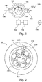
- FIG. 2 an electric motor 102 according to an embodiment of the invention is shown.
- the electric motor 102 is shown as an outer rotor motor.
- the electric motor can just as well be designed as an inner rotor motor or have a different construction.
- the rotor 201 in this embodiment comprises six rotor arms 203, each having a conductor winding 204.
- the rotor of the electric motor 202 is arranged outside the stator 201 and is constructed, for example, from a permanent magnetic material. When a current for driving the electric motor is generated in the conductor windings 204, the magnetic fields generated in the conductor windings cause the rotor 202 to rotate around the stator 201.
- a first alternating electrical current can be generated.
- This first electrical alternating current causes high-frequency magnetic fields 205, which in turn can induce eddy currents in the iron components or laminated cores of the electric motor 102.
- eddy currents are induced within the stator 201, which are arranged in a plane substantially perpendicular to the magnetic fields 205.
- These eddy currents are represented in the stator 201 by the arrow directions 206.
- the stator 201 can heat up. This heat can be delivered by the stator to the medium conveyed by the pump 101.
- a vehicle 300 according to an embodiment of the invention is shown.
- the vehicle includes an engine 301, a fuel tank 302, and a conveyor 100 that supplies the engine 301 with fuel from the fuel tank 302.
- internal combustion engine 301 is a diesel engine.
- the delivery device 100 includes a vehicle pump 101, an electric motor 102 for driving the pump, and a control unit 103 for controlling the electric motor 102.
- the control unit 103 may be, for example, a structural unit of the delivery device 100 or else part of the engine control of the internal combustion engine 301. Furthermore, the control unit 103 may also have been retrofitted in the vehicle.
- FIG. 10 is a flowchart for a method of heating a medium to be conveyed with a conveyor having a vehicle pump driven by an electric motor for conveying the medium according to an embodiment of the invention.
- the method comprises the step S1 of generating a first alternating electric current having a first frequency in at least one conductor winding of the electric motor, eddy currents being induced in a component of the conveying device by the first alternating electric current generated in the at least one conductor winding, whereby the medium is heated becomes.
Landscapes
- Engineering & Computer Science (AREA)
- Chemical & Material Sciences (AREA)
- General Engineering & Computer Science (AREA)
- Combustion & Propulsion (AREA)
- Mechanical Engineering (AREA)
- Power Engineering (AREA)
- Chemical Kinetics & Catalysis (AREA)
- Microelectronics & Electronic Packaging (AREA)
- Computer Hardware Design (AREA)
- Health & Medical Sciences (AREA)
- Toxicology (AREA)
- Structures Of Non-Positive Displacement Pumps (AREA)
- Control Of Transmission Device (AREA)
- Exhaust Gas After Treatment (AREA)
- Details And Applications Of Rotary Liquid Pumps (AREA)
Description
Fördervorrichtung zum Befördern und zum Erwärmen eines Mediums Die Erfindung betrifft eine Fördervorrichtung zum Befördern eines Mediums und zum Erwärmen des zu befördernden Mediums, ein Fahrzeug, ein Verfahren, ein Programmelement und ein computerlesbares Medium.The invention relates to a conveying device for conveying a medium and for heating the medium to be transported, a vehicle, a method, a program element and a computer-readable medium.
Üblicherweise können typische Kraftstoffpumpen für Diesel ein Pumpwerk besitzen, welches nach dem Verdrängerprinzip arbeitet. Ein Beispiel hierfür ist das sogenannte Gerotorpumpwerk. Ferner können auch Schrauben- oder Rollenzellenpumpwerke für Kraftstoffpumpen eingesetzt werden. Ebenfalls können auch Harnstofflösungspumpen, welche zur Abgasnachbehandlung eingesetzt werden, ein Pumpwerk besitzen, welches nach dem Verdrängerprinzip arbeitet. Beim Betrieb dieser Pumpen können abhängig von Druck und Viskosität des geförderten Mediums verschiedene Betriebszustände auftreten. Da ein Pumpwerk, welches nach dem Verdrängerprinzip arbeitet, eine hohe hydraulische Steifheit aufweisen kann, kann sich eine Änderung in der Viskosität oder des Drucks des geförderten Mediums direkt auf das notwendige Drehmoment zum Antrieb des Pumpwerks auswirken. Die
Dieselkraftstoff hat üblicherweise die Eigenschaft, dass bei Unterschreitung einer bestimmten Temperatur Paraffine als Flocken im Kraftstoff ausgeschieden werden können. Wird die Temperatur des Dieselkraftstoffs also gering genug, so kann dieser Mechanismus zum Versulzen und zu einer zunehmenden Verfestigung des Kraftstoffs führen. Die Viskosität des Dieselkraftstoffs kann hierbei stark ansteigen und es können nicht- oder rheolineare Viskositätsverhalten auftreten. Ab einer gewissen Veränderung der Viskosität kann wegen der genannten Gründe der normale Pumpenlauf behindert werden bzw. unmöglich werden, was sich im Falle einer mit einem elektrisch kommutierten Elektromotor angetriebenen Pumpe in wiederkehrenden Fehlstarts äußern kann. Die gleichen Mechanismen können prinzipiell auch für die Pumpen für Harnstofflösungen gelten, die für die Abgasnachbehandlung von Dieselfahrzeugen in den Abgasstrang dosiert werden. Die in Kraftfahrzeugen eingesetzten Harnstofflösungen können bei Temperaturen von etwa -8 bis -11°C gefrieren. Für die Beförderung von Dieselkraftstoff und von Harnlösungen kann es notwendig sein, eine hohe Verfügbarkeit des Fahrzeugs bzw. eine korrekte Abgasnachbehandlung auch bei großer Kälte sicherzustellen.Diesel fuel usually has the property that when falling below a certain temperature paraffins can be excreted as flakes in the fuel. Thus, if the temperature of the diesel fuel becomes low enough, this mechanism can lead to turbulence and increased solidification of the fuel. The viscosity of the diesel fuel can increase sharply and non- or rheolinear viscosity behavior can occur. From a certain change in viscosity, the normal pump running can be hindered or become impossible due to the reasons mentioned, resulting in the case of one with an electrically commutated electric motor driven pump in recurring false starts can express. In principle, the same mechanisms can also apply to the pumps for urea solutions which are metered into the exhaust gas line for the exhaust gas aftertreatment of diesel vehicles. The urea solutions used in motor vehicles can freeze at temperatures of about -8 to -11 ° C. For the transport of diesel fuel and urea solutions, it may be necessary to ensure a high availability of the vehicle or a correct exhaust aftertreatment even at high temperatures.
Die Aufgabe der Erfindung kann darin gesehen werden, die Zuverlässigkeit von Pumpen in Fahrzeugen zu erhöhen.The object of the invention can be seen to increase the reliability of pumps in vehicles.
Die Aufgabe wird gelöst durch die Gegenstände der unabhängigen Ansprüche. Weiterbildungen und Ausführungsformen sind der folgenden Beschreibung, den Figuren und den abhängigen Ansprüchen zu entnehmen.The object is solved by the subject matters of the independent claims. Further developments and embodiments are given in the following description, the figures and the dependent claims.
Ein erster Aspekt der Erfindung betrifft eine Fördervorrichtung zum Befördern eines Mediums und zum Erwärmen des zu befördernden Mediums, die eine Fahrzeugpumpe, einen Elektromotor zum Antreiben der Fahrzeugpumpe und eine Steuereinheit zum Steuern des Elektromotors aufweist. Ferner weist der Elektromotor zumindest eine Leiterwickelung auf. Außerdem ist die Steuereinheit ausgeführt, einen ersten elektrischen Wechselstrom mit einer ersten Frequenz in der zumindest einen Leiterwickelung zu erzeugen, wobei durch den in der zumindest einen Leiterwickelung erzeugten ersten elektrischen Wechselstrom in einem Bauteil der Fördervorrichtung zum Erwärmen des Mediums Wirbelströme induziert werden. Darunter kann verstanden werden, dass die Steuereinheit dazu ausgeführt ist, einen ersten elektrischen Wechselstrom mit einer ersten Frequenz derart in der zumindest einen Leiterwickelung zu erzeugen, dass in einem Bauteil der Fördervorrichtung Wirbelströme induzierbar sind.A first aspect of the invention relates to a conveying device for conveying a medium and heating the medium to be conveyed, which comprises a vehicle pump, an electric motor for driving the vehicle pump and a control unit for controlling the electric motor. Furthermore, the electric motor has at least one conductor winding. In addition, the control unit is designed to generate a first alternating electrical current with a first frequency in the at least one conductor winding, wherein eddy currents are induced by the first alternating electric current generated in the at least one conductor winding in a component of the conveying device for heating the medium. By this it can be understood that the control unit is designed to generate a first alternating electric current having a first frequency in the at least one conductor winding such that eddy currents can be induced in a component of the conveying device.
Mit anderen Worten kann eine Idee der vorliegenden Erfindung darin bestehen, dass nicht nur die Wickelungen des Elektromotors erwärmt werden, sondern auch andere Komponenten der Fördervorrichtung, beispielsweise das Eisen die Blechpakete des gesamten Elektromotors, zum Beispiel der Stator und/oder gegebenenfalls der Rotor des Elektromotors. Dies kann durch eine Einprägung hochfrequenter Ströme in die Leiterwickelung des Elektromotors erfolgen. Um das Bauteil der Fördervorrichtung zu erwärmen, kann die Leiterwickelung mit Wechselströmen höherer Frequenz beaufschlagt werden. Hierdurch können sich hochfrequente Magnetfelder im Bauteil ausbilden, die zu entsprechenden Wirbelströmen im Bauteil und zu einer entsprechenden Wärmeentwicklung führen können. Die erforderlichen Wechselströme können im Vergleich mit einer Gleichstrombeheizung relativ klein sein, da die Erwärmung des Bauteils durch Ummagnetisierungsverluste im Bauteil selbst erzeugt werden können und nicht durch den Ohmschen Widerstand der Leiterwickelung erzeugt werden müssen. Damit können eventuelle Steckkontakte von Anschlusssteckern und eine eventuelle Endstufe der Steuereinheit kleiner und kostengünstiger ausgelegt werden. Ferner kann die auf diese Weise ohne Schäden in die Pumpe eintragbare elektrische Leistung deutlich höher sein als bei der Erwärmung der Wickelung durch Gleichströme. Damit kann das in der Pumpe befindliche Medium schneller verflüssigt werden. Da der Wärmewiderstand der Gesamtpumpe zur Umgebung und zu dem im Pumpeninneren befindlichen Medium im Vergleich zu einer einzelnen Wickelung geringer sein kann, kann auch die Umgebung der Pumpe besser erwärmt werden, wodurch ein gewisser Vorrat an flüssigem Medium erhalten werden kann. Auf diese Weise kann das in der Pumpe befindliche Medium schneller erwärmt werden, wodurch die Zuverlässigkeit der Fördervorrichtung erhöht werden kann.In other words, an idea of the present invention is that not only the windings of the electric motor are heated, but also other components of the conveyor, such as iron, the laminations of the entire electric motor, for example, the stator and / or optionally the rotor of the electric motor , This can be done by impressing high-frequency currents in the conductor winding of the electric motor. To heat the component of the conveyor, the conductor winding can be acted upon by alternating currents of higher frequency. As a result, high-frequency magnetic fields can form in the component, which can lead to corresponding eddy currents in the component and to a corresponding evolution of heat. The required AC currents can be relatively small compared to a DC heating, since the heating of the component can be generated by Ummagnetisierungsverluste in the component itself and need not be generated by the ohmic resistance of the conductor winding. Thus, any plug contacts of connectors and a possible power amplifier of the control unit can be designed smaller and cheaper. Furthermore, the electrical power that can be introduced in this way without damage to the pump can be significantly higher than when the winding is heated by direct currents. Thus, the medium in the pump can be liquefied faster. Since the thermal resistance of the overall pump to the environment and the medium inside the pump can be lower compared to a single winding, the environment of the pump can be better heated, whereby a certain supply of liquid medium can be obtained. In this way, the medium in the pump can be heated faster, whereby the reliability of the conveyor can be increased.
Dabei kann der Begriff "Fördervorrichtung" im Kontext der vorliegenden Erfindung in einem weiten Sinne verstanden werden. So muss die Fördervorrichtung nicht zwingendermaßen eine einzelne bauliche Einheit sein. Beispielsweise können die Fahrzeugpumpe, der Elektromotor und die Steuereinheit unterschiedliche bauliche Einheiten sein. Die Steuereinheit kann beispielsweise ein Teil der Motorsteuerung sein. Beim zum befördernden Medium kann es sich beispielsweise um Kraftstoff, um Dieselkraftstoff, um Scheibenwasser, um Harnstoff und/oder um Motor- bzw. Getriebeöl handeln. Allgemein kann es sich beim Medium um ein Medium handeln, bei dem an einer gewissen Temperatur mit einer Erstarrung des Mediums zu rechnen ist. Die Fahrzeugpumpe kann verschiedene Pumpenarten bezeichnen. Beispielsweise kann die Fahrzeugpumpe als Strömungspumpe, als Gerotorpumpe, als Schraubenpumpe oder als Rollenzellenpumpe realisiert sein. Das heißt, die vorliegende Erfindung ist auf verschiedene Pumpenarten anwendbar. Im Kontext der vorliegenden Erfindung kann unter einer Fahrzeugpumpe eine Pumpe, welche im Automobilbereich eingesetzt werden kann, verstanden werden. Der Elektromotor kann beispielsweise einen mechanisch kommutierten oder einen elektrisch kommutierten Elektromotor bezeichnen. Im Falle des elektrisch kommutierten Elektromotors kann die Steuereinheit beispielsweise gleichzeitig eine Regeleinheit sein, die zum Antrieb des Elektromotors die Stromzufuhr zum Elektromotor regelt. Die Leiterwickelung des Elektromotors kann beispielsweise am Rotor oder am Stator des Elektromotors angebracht sein. Dies kann davon abhängig sein, wie genau der Elektromotor konstruiert ist. Beispielsweise kann bei einem elektrisch kommutierten Elektromotor die Leiterwickelung am Stator angeordnet sein, wohingegen bei einem mechanisch kommutierten Elektromotor die Leiterwickelung am Rotor angebracht sein kann. Ferner können auch mehrere Leiterwickelungen im Elektromotor angeordnet sein. Unter dem ersten elektrischen Wechselstrom, der in der zumindest einen Leiterwickelung erzeugt wird, kann ein hochfrequenter elektrischer Wechselstrom verstanden werden. Dieser hochfrequente Wechselstrom kann wiederum hochfrequente Magnetfelder im Bauteil der Fördervorrichtung erzeugen. Dieses Bauteil kann beispielsweise ein Eisenbauteil bzw. ein Blechpaket des Elektromotors sein. Zum Beispiel handelt es sich dabei um den Stator oder gegebenenfalls um den Rotor des Elektromotors. Ferner können auch separate Bauteile außerhalb des Elektromotors angebracht sein, welche ausgeführt sind, durch die erzeugten Wirbelströme erwärmt zu werden. Diese Bauteile können speziell für diesen Zweck konstruiert sein.The term "conveyor" in the context of the present invention may be understood in a broad sense. So the conveyor need not necessarily be a single structural unit. For example, the vehicle pump, the electric motor and the control unit may be different structural units. The control unit may for example be part of the engine control. The medium to be transported may be, for example, fuel, diesel fuel, windscreen water, urea and / or engine or transmission oil. In general, the medium can be a medium in which solidification of the medium can be expected at a certain temperature. The vehicle pump may refer to different types of pumps. For example, the vehicle pump may be realized as a flow pump, as a gerotor pump, as a screw pump or as a roller-cell pump. That is, the present invention is applicable to various types of pumps. In the context of the present invention, a pump may be understood to mean a pump which may be used in the automotive field. The electric motor may, for example, designate a mechanically commutated or an electrically commutated electric motor. In the case of the electrically commutated electric motor, the control unit may for example be simultaneously a control unit, which regulates the power supply to the electric motor for driving the electric motor. The conductor winding of the electric motor can be mounted, for example, on the rotor or on the stator of the electric motor. This may depend on how exactly the electric motor is designed. For example, in the case of an electrically commutated electric motor, the conductor winding may be arranged on the stator, whereas in the case of a mechanically commutated electric motor the conductor winding may be mounted on the rotor. Furthermore, a plurality of conductor windings can also be arranged in the electric motor. Under the first electrical alternating current, which is generated in the at least one conductor winding, a high-frequency electrical alternating current can be understood. This high-frequency alternating current can in turn generate high-frequency magnetic fields in the component of the conveying device. This component can, for example be an iron component or a laminated core of the electric motor. For example, this is the stator or possibly the rotor of the electric motor. Further, separate components may be mounted outside of the electric motor, which are designed to be heated by the generated eddy currents. These components can be specially designed for this purpose.
In modernen Kraftfahrzeugen können Kraftstoff- und/oder Harnstofflösungspumpe typischerweise als Pumpe, welche mit elektrisch kommutierten Elektromotoren angetrieben werden, ausgeführt sein. Die elektronische Steuerung bzw. Regelung des Elektromotors kann ferner eine Blockierung der Pumpe feststellen.In modern motor vehicles, fuel and / or urea solution pumps may typically be embodied as a pump driven by electrically commutated electric motors. The electronic control of the electric motor can also detect a blockage of the pump.
Die Erwärmung kann so lange erfolgen, bis das Medium in der Pumpe und in unmittelbarer Umgebung der Pumpe verflüssigt ist. Dabei kann die Erwärmung von Umgebungsbedingungen abhängen. Ferner kann das Medium erwärmt werden, bis dessen Temperatur einige Grad über dem Erstarrungspunkt des Mediums ist. Dabei kann der Betrag der Erwärmung bzw. die erreichte Temperatur des Mediums von der Zeitdauer des Heizbetriebs abhängig sein.The heating can be carried out until the medium in the pump and in the immediate vicinity of the pump is liquefied. The heating may depend on ambient conditions. Further, the medium may be heated until its temperature is a few degrees above the solidification point of the medium. In this case, the amount of heating or the temperature reached of the medium may be dependent on the duration of the heating operation.
Der erste elektrische Wechselstrom bzw. die Heizströme können ferner in der gleichen Größenordnung wie die normalen Betriebsströme zum Antrieb des Elektromotors, im Folgenden als zweiter elektrischer Wechselstrom bezeichnet, sein. Damit kann die Dimensionierung der Kontakte und der Leistungselektronik des Elektromotors für die Erzeugung der Heizströme sowie der Betriebsströme gleich bleiben, da hier keine nennenswert höheren Belastungen im Vergleich zum Normalbetrieb auftreten müssen.The first alternating electrical current or the heating currents can also be of the same order of magnitude as the normal operating currents for driving the electric motor, hereinafter referred to as second alternating electrical current. Thus, the dimensioning of the contacts and the power electronics of the electric motor for the generation of the heating currents and the operating currents remain the same, since no appreciably higher loads compared to normal operation must occur here.
Gemäß einer beispielhaften Ausführungsform der Erfindung ist der erste elektrische Wechselstrom derart ausgeführt, dass er ein Magnetfeld im Elektromotor erzeugt, das kein Drehfeld ist. Dabei kann das Magnetfeld durch den ersten elektrischen Wechselstrom in der zumindest einen Leiterwickelung erzeugt werden. Ferner kann unter einem Drehfeld ein Magnetfeld verstanden werden, das sich um eine Rotationsachse dreht. Mit anderen Wortet kann dies bedeuten, dass das durch den ersten Wechselstrom erzeugte Magnetfeld nicht rotiert. Beziehungsweise kann dies bedeuten, dass der erste elektrische Wechselstrom kein Antriebsmoment für den Elektromotor erzeugt. Beispielsweise muss der erste elektrische Wechselstrom nicht in einem Blockmuster angelegt werden. Zum Beispiel kann eine Wechselspannung an eine oder mehrere Leiterwicklungen angelegt werden, die einen Wechselstrom durch diese Leiterwickelung oder Leiterwickelungen treibt. Das im inneren entstehende Feld kann hierbei ein reines Wechselfeld ohne Drehkomponente sein. Der Rotor kann hierbei stehen bzw. muss nicht rotieren. Dadurch, dass in diesem Fall der erste elektrische Wechselstrom kein Antriebsmoment erzeugt, kann die das Medium geheizt werden, ohne dass der Elektromotor angetrieben wird.According to an exemplary embodiment of the invention, the first alternating electric current is designed such that it generates a magnetic field in the electric motor which is not a rotating field. In this case, the magnetic field can be generated by the first alternating electric current in the at least one conductor winding. Furthermore, a rotating field can be understood to mean a magnetic field which rotates about an axis of rotation. In other words, this may mean that the magnetic field generated by the first alternating current is not rotating. Respectively, this may mean that the first alternating electric current does not generate a drive torque for the electric motor. For example, the first alternating electric current does not have to be applied in a block pattern. For example, an AC voltage may be applied to one or more conductor windings that drives an AC current through these conductor windings or conductor windings. The field that arises in this case can be a pure alternating field without a rotation component. The rotor can stand here or does not have to rotate. Characterized in that in this case the first alternating electric current does not generate a driving torque, the medium can be heated without the electric motor is driven.
Gemäß einer beispielhaften Ausführungsform der Erfindung weist der Elektromotor einen Rotor und einen Stator auf, wobei die zumindest eine Leiterwickelung am Stator angeordnet ist. Durch den in der zumindest einen Leiterwickelung erzeugten ersten elektrischen Wechselstrom werden im Stator des Elektromotors Wirbelströme induziert. Mit anderen Worten, können durch den in der zumindest einen Leiterwickelung erzeugten ersten elektrischen Wechselstrom im Stator des Elektromotors Wirbelströme induzierbar sein.According to an exemplary embodiment of the invention, the electric motor has a rotor and a stator, wherein the at least one conductor winding is arranged on the stator. The first alternating electric current generated in the at least one conductor winding induces eddy currents in the stator of the electric motor. In other words, eddy currents can be induced in the stator of the electric motor by the first alternating electric current generated in the at least one conductor winding.
Dabei kann es sich beispielsweise beim Elektromotor um einen elektrisch kommutierten Elektromotor handeln. In diesem Falle kann die Steuereinheit in der für den elektrisch kommutierten Elektromotor benötigten Elektronik realisiert sein. Auf diese Weise sind keine zusätzlichen Bauteile für die Fördervorrichtung erforderlich, wodurch die erfindungsgemäße Fördervorrichtung einfach zu realisieren ist, einfach nachrüstbar ist und zuverlässiger betrieben werden kann, da durch die geringere Anzahl an Bauteilen die Ausfallswahrscheinlichkeit gesenkt werden kann. Ferner kann die Fördervorrichtung auch kostengünstig hergestellt werden.For example, the electric motor may be an electrically commutated electric motor. In this case, the control unit can be realized in the electronics required for the electrically commutated electric motor. In this way, no additional components for the conveyor required, whereby the conveyor device according to the invention is easy to implement, is easy to retrofit and can be operated reliably, since the probability of failure can be reduced by the smaller number of components. Furthermore, the conveyor can also be produced inexpensively.
Gemäß der Erfindung ist die Steuereinheit weiterhin ausgeführt, zum Antreiben des Elektromotors einen zweiten elektrischen Wechselstrom mit einer zweiten Frequenz in der zumindest einen Leiterwickelung zu erzeugen, wobei der zweite elektrische Wechselstrom ein Drehfeld im Elektromotor erzeugt.According to the invention, the control unit is further designed to generate a second alternating electrical current with a second frequency in the at least one conductor winding for driving the electric motor, wherein the second alternating electric current generates a rotating field in the electric motor.
Dabei kann unter einem Drehfeld ein Magnetfeld verstanden werden, welches sich um eine Rotationsachse dreht, beispielsweise um die Antriebsachse des Elektromotors. Mit anderen Worten wird mit dem zweiten elektrischen Wechselstrom ein Antriebsmoment erzeugt. Durch das Bereitstellen der Steuereinheit, die gleichzeitig Ströme zur Heizung und zum Antrieb erzeugt werden, wird eine einfache Lösung bereitgestellt, um das in der Fördervorrichtung befindliche Medium zu befördern und zu erwärmen. Ferner kann diese Fördervorrichtung einfach mit der Heizfunktionalität nachgerüstet werden und kann auch zuverlässiger sein, da keine extra Bauteile erforderlich sind, welche eine höhere Ausfallwahrscheinlichkeit bewirken könnten.In this case, a magnetic field can be understood as a magnetic field which rotates about an axis of rotation, for example about the drive axis of the electric motor. In other words, a drive torque is generated with the second alternating electric current. By providing the control unit, which simultaneously generates currents for heating and driving, a simple solution is provided to convey and heat the medium in the conveyor. Furthermore, this conveyor can be easily retrofitted with the heating functionality and can also be more reliable because no extra components are required, which could cause a higher probability of failure.
Gemäß einer weiteren beispielhaften Ausführungsform der Erfindung ist die Steuereinheit ausgeführt, den ersten elektrischen Wechselstrom mit der ersten Frequenz, die zwischen 500 Hz und 50 kHz beträgt, in der zumindest einen Leiterwickelung zu erzeugen.According to a further exemplary embodiment of the invention, the control unit is designed to generate the first alternating electrical current of the first frequency, which is between 500 Hz and 50 kHz, in the at least one conductor winding.
Dabei kann die Frequenz des ersten elektrischen Wechselstroms abhängig vom Design der Fördervorrichtung sein, z. B. von der Blechdicke und gegebenenfalls vom Ansteuermuster mehrerer Leiterwickelungen. Da die Erwärmung durch im Eisen induzierte Wirbelströme entstehen kann, kann der Elektromotor zur Heizung mit Spannungen und Strömen ähnlich dem Normalbetrieb beaufschlagt werden. Für typische Kfz-Pumpen können die Spannung 12V und die Ströme 8 bis 20 A betragen. Die Verluste zur Erwärmung des Mediums können dann durch die vergleichsweise hohen Wirbelströme im Eisenwiderstand entstehen. Es kann sich hierbei um einen Transformatoreffekt, bei dem ein hoher Sekundärstrom ohmsche Verluste erzeugen kann, handeln. Die Primärwicklung kann hierbei nur einen vergleichsweise kleinen Strom führen und kann somit kleine ohmsche Verluste aufweisen. Ferner können zur Heizung Wechselströme beaufschlagt werden, die eine Frequenz aufweisen, welche oberhalb des Hörbereichs ist. Dadurch kann eine Geräuschentwicklung der Fördervorrichtung vermieden werden. Wenn jedoch ein erster Wechselstrom im hörbaren Frequenzbereich erforderlich sein sollte, beispielsweise wegen des Impedanzverlaufs der Wicklungsinduktivität, kann die Frequenz derart gewählt werden, dass die Geräuschentwicklung minimiert wird.In this case, the frequency of the first alternating electrical current may be dependent on the design of the conveying device, for. B. of the Sheet thickness and possibly the driving pattern of several conductor windings. Since the heating can occur due to iron-induced eddy currents, the electric motor for heating can be subjected to voltages and currents similar to normal operation. For typical automotive pumps, the voltage may be 12V and the currents 8 to 20A. The losses for heating the medium can then arise due to the comparatively high eddy currents in the iron resistance. This can be a transformer effect in which a high secondary current can generate ohmic losses. In this case, the primary winding can only conduct a comparatively small current and can thus have small ohmic losses. Furthermore, alternating currents can be applied to the heating, which have a frequency which is above the audible range. Thereby, a noise of the conveyor can be avoided. However, if a first alternating current in the audible frequency range should be required, for example due to the impedance characteristic of the winding inductance, the frequency can be chosen such that the noise is minimized.
Gemäß einer weiteren beispielhaften Ausführungsform der Erfindung weist die Fördervorrichtung einen Temperatursensor zum Messen einer Temperatur des zu befördernden Mediums auf. Ferner ist die Steuereinheit ausgeführt, den ersten elektrischen Wechselstrom in der zumindest einen Leiterwickelung zu erzeugen, wenn die vom Temperatursensor gemessene Temperatur einen vorgegebenen Temperaturgrenzwert unterschreitet.According to another exemplary embodiment of the invention, the conveying device has a temperature sensor for measuring a temperature of the medium to be transported. Further, the control unit is designed to generate the first alternating electrical current in the at least one conductor winding when the temperature measured by the temperature sensor falls below a predetermined temperature limit.
Der Temperatursensor kann beispielsweise in der Pumpe oder in einer Zu- bzw. Ableitung der Pumpe angeordnet sein. In diesem Fall kann mit dem Temperatursensor eine Temperatur des beförderten Mediums gemessen werden. Ferner kann der Temperatursensor auch in der Steuereinheit angeordnet sein. Der Temperatursensor kann in diesem Fall die Umgebungstemperatur messen. Außerdem kann der Temperatursensor auch Teil der Elektronik des Elektromotors sein, um die inneren Temperaturen im Gerät zu erfassen. Der Temperaturgrenzwert kann beispielsweise einen Grenzwert bezeichnen, bei dessen Unterschreiten durch die Temperatur des Mediums die Viskosität des Mediums zu groß wird. Wenn eine Blockierung der Pumpe bei gleichzeitig geringer Umgebungstemperatur festgestellt wird, kann die Blockierung durch ein erstarrtes Medium ausgelöst worden sein. Auf diese Weise kann die Fördervorrichtung dann heizen, wenn eine Gefahr einer Blockierung der Fahrzeugpumpe durch eine zu hohe Viskosität des Mediums besteht.The temperature sensor can be arranged for example in the pump or in an inlet or outlet of the pump. In this case, a temperature of the conveyed medium can be measured with the temperature sensor. Furthermore, the temperature sensor can also be arranged in the control unit. The temperature sensor can measure the ambient temperature in this case. In addition, the temperature sensor can also be part of the electronics of Electric motor to detect the internal temperatures in the device. The temperature limit value may, for example, designate a limit value below which the viscosity of the medium becomes too great due to the temperature of the medium. If a blockage of the pump is detected at low ambient temperature, the blockage may have been triggered by a solidified medium. In this way, the conveyor device can then heat when there is a risk of blockage of the vehicle pump due to excessive viscosity of the medium.
Gemäß einer weiteren beispielhaften Ausführungsform der Erfindung weist die Fördervorrichtung einen Temperatursensor zum Messen einer Temperatur des zu befördernden Mediums auf. Ferner ist die Steuereinheit ausgeführt, eine Blockade des Elektromotors zu detektieren. Außerdem ist die Steuereinheit ausgeführt, den ersten elektrischen Wechselstrom in der zumindest einen Leiterwickelung zu erzeugen, wenn die Steuereinheit die Blockade des Elektromotors detektiert und die vom Temperatursensor gemessene Temperatur des zu befördernden Mediums den vorgegebenen Temperaturgrenzwert unterschreitet.According to another exemplary embodiment of the invention, the conveying device has a temperature sensor for measuring a temperature of the medium to be transported. Furthermore, the control unit is designed to detect a blockage of the electric motor. In addition, the control unit is designed to generate the first alternating electric current in the at least one conductor winding when the control unit detects the blockage of the electric motor and the temperature of the medium to be transported, measured by the temperature sensor, falls below the predetermined temperature limit value.
Auf diese Weise kann bei einer Blockade der Fahrzeugpumpe das Medium in der Fahrzeugpumpe automatisch wieder erwärmt werden, wodurch ein normaler Betrieb der Fahrzeugpumpe schnell wiederhergestellt werden kann. Ferner kann das Erwärmen des Mediums auch vor dem Benutzen der Fahrzeugpumpe erfolgen, wenn beispielsweise das Medium in der Fahrzeugpumpe eine tiefere Temperatur aufweist.In this way, in a blockage of the vehicle pump, the medium in the vehicle pump can be automatically reheated, whereby a normal operation of the vehicle pump can be quickly restored. Furthermore, the heating of the medium can also take place before the use of the vehicle pump, if, for example, the medium in the vehicle pump has a lower temperature.
Ein zweiter Aspekt der Erfindung betrifft ein Fahrzeug mit einer Fördervorrichtung, welche im Kontext der vorliegenden Erfindung beschrieben ist, wobei die Fahrzeugpumpe eine Kraftstoffpumpe zum Befördern von Kraftstoff für einen Verbrennungsmotor oder eine Harnstofflösungspumpe ist.A second aspect of the invention relates to a vehicle having a delivery device described in the context of the present invention, wherein the vehicle pump is a fuel pump for delivering fuel to an internal combustion engine or a urea solution pump.
Da es sich um eine Fördervorrichtung handelt, welche im Kontext der vorliegenden Erfindung beschrieben ist, sind Merkmale und Vorteile, welche im Zusammenhang mit der Fördervorrichtung genannt werden, auch auf das Fahrzeug anwendbar. Das Fahrzeug kann beispielsweise ein Personenkraftfahrzeug oder ein Lastkraftfahrzeug sein, welches durch einen Verbrennungsmotor angetrieben wird. Ferner kann das Fahrzeug auch mit einem Hybridantrieb ausgestattet sein.Since it is a conveying device described in the context of the present invention, features and advantages mentioned in connection with the conveying device are also applicable to the vehicle. The vehicle may be, for example, a passenger car or a truck powered by an internal combustion engine. Furthermore, the vehicle may also be equipped with a hybrid drive.
Ein dritter Aspekt der Erfindung betrifft ein Verfahren zum Erwärmen eines zu befördernden Mediums mit einer Fördervorrichtung, welche eine mit einem Elektromotor angetriebene Fahrzeugpumpe zum Befördern des Mediums aufweist. Dabei weist das Verfahren den Schritt des Erzeugens eines ersten elektrischen Wechselstroms mit einer ersten Frequenz in zumindest einer Leiterwickelung des Elektromotors auf. Durch den in der zumindest einen Leiterwickelung erzeugten ersten elektrischen Wechselstrom werden Wirbelströme in einem Bauteil der Fördervorrichtung induziert, wodurch das Medium erwärmt wird.A third aspect of the invention relates to a method for heating a medium to be conveyed with a conveying device which has a vehicle pump driven by an electric motor for conveying the medium. In this case, the method comprises the step of generating a first alternating electrical current with a first frequency in at least one conductor winding of the electric motor. By means of the first alternating electric current generated in the at least one conductor winding, eddy currents are induced in a component of the conveying device, whereby the medium is heated.
Dieses Verfahren kann beispielsweise in einer Steuereinheit einer im Kontext der vorliegenden Erfindung beschriebenen Fördervorrichtung ausgeführt werden. Daher können Merkmale und Vorteile, die im Zusammenhang mit der Fördervorrichtung genannt werden, auch auf das Verfahren angewendet werden. Ferner können die Schritte des Verfahrens in verschiedenen Reihenfolgen und/oder parallel durchgeführt werden.This method may, for example, be carried out in a control unit of a conveyor device described in the context of the present invention. Therefore, features and advantages mentioned in connection with the conveyor may also be applied to the method. Furthermore, the steps of the method may be performed in different orders and / or in parallel.
Ein vierter Aspekt der Erfindung betrifft ein Programmelement, das, wenn es von einer Steuereinheit einer Fördervorrichtung ausgeführt wird, die Steuereinheit anleitet, ein Verfahren, welches oben und im Folgenden beschrieben ist, durchzuführen.A fourth aspect of the invention relates to a program element which, when executed by a control unit of a conveying apparatus, instructs the control unit to perform a method described above and hereinafter.
Das Programmelement kann ein Teil eines Computerprogramms sein. Ferner kann das Programmelement auch selbst ein selbstständiges Computerprogramm sein. Beispielsweise kann das Programmelement als Update ein bereits bestehendes Computerprogramm zum Ausführen des erfindungsgemäßen Verfahrens befähigen.The program element may be part of a computer program. Furthermore, the program element itself may be an independent computer program. For example, the program element as an update can enable an existing computer program for carrying out the method according to the invention.
Ein fünfter Aspekt der Erfindung betrifft ein computerlesbares Medium, auf dem ein Programmelement gespeichert ist, das, wenn es von einer Steuereinheit einer Fördervorrichtung ausgeführt wird, die Steuereinheit anleitet, ein im Kontext der Erfindung beschriebenes Verfahren durchzuführen.A fifth aspect of the invention relates to a computer-readable medium having stored thereon a program element which, when executed by a control unit of a conveyor, instructs the control unit to perform a method described in the context of the invention.
Das computerlesbare Medium kann als Speichermedium, beispielsweise als USB-Stick, als CD, als DVD, als Festplatte oder als sonstiges Speichermedium angesehen werden. Ferner kann das computerlesbare Medium auch als Mikrochip ausgeführt sein, der eine Steuerungseinheit befähigt, das erfindungsgemäße Verfahren durchzuführen.The computer-readable medium can be regarded as a storage medium, for example as a USB stick, as a CD, as a DVD, as a hard disk or as another storage medium. Furthermore, the computer-readable medium can also be designed as a microchip, which enables a control unit to carry out the method according to the invention.
Die beschriebenen Ausführungsformen betreffen gleichermaßen eine Fördervorrichtung, ein Fahrzeug, ein Verfahren, ein Programmelement und ein computerlesbares Medium, obwohl einzelne Ausführungsformen ausschließlich in Bezug zu der Fördervorrichtung, dem Fahrzeug, dem Verfahren, dem Programmelement oder dem computerlesbaren Medium beschrieben werden. Synergetische Effekte können sich aus verschiedenen Kombinationen der Ausführungsformen ergeben, auch wenn diese im Folgenden nicht beschrieben werden.The described embodiments equally relate to a conveyor, a vehicle, a method, a program element, and a computer-readable medium, although individual embodiments are described solely with respect to the conveyor, vehicle, method, program element, or computer-readable medium. Synergistic effects may result from various combinations of embodiments, although not described below.
Weitere Merkmale, Vorteile und Anwendungsmöglichkeiten der Erfindung ergeben sich aus der nachfolgenden Beschreibung der Ausführungsbeispiele und der Figuren. Dabei bilden alle beschriebenen und/oder bildlich dargestellten Merkmale für sich und in beliebiger Kombination den Gegenstand der Erfindung auch unabhängig von ihrer Zusammensetzung in den einzelnen Ansprüchen oder deren Rückbezügen.
- Fig. 1
- zeigt eine Fördervorrichtung gemäß einem Ausführungsbeispiel der Erfindung.
- Fig. 2
- zeigt einen Elektromotor gemäß einem Ausführungsbeispiel der Erfindung.
- Fig. 3
- zeigt ein Fahrzeug gemäß einem Ausführungsbeispiel der Erfindung.
- Fig. 4
- zeigt ein Flussdiagramm eines Verfahrens gemäß einem Ausführungsbeispiel der Erfindung.
- Fig. 1
- shows a conveyor device according to an embodiment of the invention.
- Fig. 2
- shows an electric motor according to an embodiment of the invention.
- Fig. 3
- shows a vehicle according to an embodiment of the invention.
- Fig. 4
- shows a flowchart of a method according to an embodiment of the invention.
Dabei sind die Figuren schematisch und nicht maßstabsgetreu dargestellt.The figures are shown schematically and not to scale.
In
Gemäß dem in
Ferner ist in
In
In
In
Ergänzend sei darauf hinzuweisen, dass "umfassend" oder "aufweisend" keine anderen Elemente ausschließt und "ein" oder "einer" keine Vielzahl ausschließt. Ferner sei darauf hingewiesen, dass Merkmale, die mit Verweis auf eines der obigen Ausführungsbeispiele oder Ausführungsformen beschrieben worden sind, auch in Kombination mit anderen Merkmalen anderer zuvor beschriebener Ausführungsbeispiele oder Ausführungsformen verwendet werden können. Bezugszeichen in den Ansprüchen sind nicht als Einschränkungen anzusehen.In addition, it should be noted that "comprising" or "having" does not exclude other elements and "a" or "one" does not exclude a plurality. It should also be appreciated that features described with reference to any of the above embodiments or embodiments may also be used in combination with other features of other previously described embodiments or embodiments. Reference signs in the claims are not to be considered as limitations.
Claims (9)
- Delivery device (100) for delivering a medium and for heating the medium for delivery, the delivery device having:a vehicle pump (101);an electric motor (102) for driving the vehicle pump;a control unit (103) for controlling the electric motor;wherein the electric motor has at least one conductor winding (204);wherein the control unit is designed to generate a first electrical alternating current with a first frequency in the at least one conductor winding; andwherein, by means of the first electrical alternating current generated in the at least one conductor winding, eddy currents (206) are induced in a component of the delivery device for the purposes of heating the medium,characterized in that the control unit is furthermore designed to generate, simultaneously with the first electrical alternating current, a second electrical alternating current with a second frequency in the at least one conductor winding for the purposes of driving the electric motor;wherein the second electrical alternating current generates a rotating field in the electric motor.
- Delivery device according to Claim 1,
wherein the electric motor has a rotor (202) and a stator (201) ;
wherein the at least one conductor winding is arranged on the stator; and
wherein, by means of the first electrical alternating current generated in the at least one conductor winding, eddy currents are induced in the stator of the electric motor. - Delivery device according to one of the preceding claims, wherein the control unit is designed to generate the first electrical alternating current in the at least one conductor winding with the first frequency, which amounts to between 500 Hz and 50 kHz.
- Delivery device according to one of the preceding claims, the delivery device furthermore having:a temperature sensor (110) for measuring a temperature of the medium for delivery;wherein the control unit is designed to generate the first electrical alternating current in the at least one conductor winding if the temperature of the medium to be delivered as measured by the temperature sensor differs from a predefined temperature threshold value.
- Delivery device according to one of Claims 1 to 4, the delivery device furthermore having:a temperature sensor for measuring a temperature of the medium for delivery;wherein the control unit is designed to detect a blockage of the electric motor;wherein the control unit is designed to generate the first electrical alternating current in the at least one conductor winding if the control unit detects the blockage of the electric motor and the temperature of the medium for delivery as measured by the temperature sensor falls below the predefined temperature threshold value.
- Vehicle (300) having a delivery device (100) according to one of the preceding claims;
wherein the vehicle pump is a fuel pump for delivering fuel for an internal combustion engine, or a urea solution pump. - Method for heating a medium for delivery by means of a delivery device, which has a vehicle pump, driven by means of an electric motor, for delivering the medium, the method having the step:generating a first electrical alternating current with a first frequency in at least one conductor winding of the electric motor (S1);wherein, by means of the first electrical alternating current generated in the at least one conductor winding, eddy currents are induced in a component of the delivery device, whereby the medium is heated;generating a second electrical alternating current with a second frequency in at least one conductor winding of the electric motor (S1);wherein the generation of the second electrical alternating current is performed simultaneously with the generation of the first electrical alternating current; andwherein a rotating field is generated in the electric motor, for the purposes of driving the electric motor, by means of the second electrical alternating current generated in the at least one conductor winding.
- Program element which, when executed by a control unit of a delivery device, commands the control unit to carry out a method according to Claim 7.
- Computer-readable medium (109) on which there is stored a program element which, when executed by a control unit of a delivery device, commands the control unit to carry out a method according to Claim 7.
Applications Claiming Priority (2)
| Application Number | Priority Date | Filing Date | Title |
|---|---|---|---|
| DE102014226835 | 2014-12-22 | ||
| PCT/EP2015/079920 WO2016102257A1 (en) | 2014-12-22 | 2015-12-16 | Delivery device for delivering and heating a medium |
Publications (2)
| Publication Number | Publication Date |
|---|---|
| EP3237745A1 EP3237745A1 (en) | 2017-11-01 |
| EP3237745B1 true EP3237745B1 (en) | 2019-02-20 |
Family
ID=55024108
Family Applications (1)
| Application Number | Title | Priority Date | Filing Date |
|---|---|---|---|
| EP15816431.9A Active EP3237745B1 (en) | 2014-12-22 | 2015-12-16 | Device for feeding for the conveying and for heating a medium |
Country Status (4)
| Country | Link |
|---|---|
| US (1) | US10415521B2 (en) |
| EP (1) | EP3237745B1 (en) |
| CN (1) | CN107002606B (en) |
| WO (1) | WO2016102257A1 (en) |
Families Citing this family (4)
| Publication number | Priority date | Publication date | Assignee | Title |
|---|---|---|---|---|
| DE102018200690A1 (en) * | 2018-01-17 | 2019-07-18 | Robert Bosch Gmbh | Operating method for an electronically commutated motor, control unit, device and working device |
| DE102018105129A1 (en) * | 2018-03-06 | 2019-09-12 | Gkn Sinter Metals Engineering Gmbh | Method for operating an electric motor |
| DE102018105136A1 (en) * | 2018-03-06 | 2019-09-12 | Gkn Sinter Metals Engineering Gmbh | Method for operating a pump arrangement |
| DE102020118495A1 (en) * | 2020-07-14 | 2022-01-20 | Bayerische Motoren Werke Aktiengesellschaft | Pump device of a wiper water system of a vehicle and wiper water system of a vehicle with such a pump device |
Family Cites Families (15)
| Publication number | Priority date | Publication date | Assignee | Title |
|---|---|---|---|---|
| FR2044519A5 (en) * | 1969-05-23 | 1971-02-19 | Sopromi Soc Proc Modern Inject | |
| DE3207436A1 (en) * | 1982-02-27 | 1983-09-08 | Franz Klaus Union Armaturen, Pumpen Gmbh & Co, 4630 Bochum | DEVICE AND AGGREGATE FOR HEATING A FLOWING MEDIUM |
| ATE77872T1 (en) * | 1986-11-20 | 1992-07-15 | Hermetic Pumpen Gmbh | PUMP WITH CANNED TUBE MOTOR OR CANNEED TUBE MAGNETIC CLUTCH DRIVE. |
| DE3639719C3 (en) | 1986-11-20 | 1994-02-24 | Hermetic Pumpen Gmbh | Canned magnet pump |
| DE3729938C1 (en) * | 1987-09-07 | 1989-03-30 | Eberspaecher J | Device for conveying and preheating fuel sensitive to cold |
| US5159915A (en) * | 1991-03-05 | 1992-11-03 | Nippon Soken, Inc. | Fuel injector |
| US7634241B2 (en) * | 2005-07-29 | 2009-12-15 | Broadcom Corporation | MIMO radio interfaces |
| US8666712B2 (en) * | 2006-07-24 | 2014-03-04 | Ati Technologies Inc. | Physical simulations on a graphics processor |
| DE102007011456A1 (en) * | 2007-03-09 | 2008-09-11 | Dr. Ing. H.C. F. Porsche Aktiengesellschaft | Method for operating a fuel pump |
| US8694230B2 (en) * | 2009-05-19 | 2014-04-08 | Sturman Digital Systems, Llc | Fuel systems and methods for cold environments |
| WO2010142042A1 (en) * | 2009-06-09 | 2010-12-16 | Magna Powertrain Inc. | Dual power input fluid pump |
| DE102010027838A1 (en) | 2010-04-16 | 2011-10-20 | Robert Bosch Gmbh | Electric feed pump and method for driving an electric feed pump |
| DE102010035039A1 (en) * | 2010-08-20 | 2012-02-23 | Pierburg Gmbh | Pump with an electric motor and method for switching on such a pump |
| US20120211093A1 (en) | 2011-02-22 | 2012-08-23 | Micropump, Inc. | Pump assemblies with freeze-preventive heating |
| US9528524B2 (en) * | 2011-10-31 | 2016-12-27 | Regal Beloit America, Inc. | Pump freeze protection |
-
2015
- 2015-12-16 CN CN201580062918.1A patent/CN107002606B/en active Active
- 2015-12-16 WO PCT/EP2015/079920 patent/WO2016102257A1/en active Application Filing
- 2015-12-16 EP EP15816431.9A patent/EP3237745B1/en active Active
- 2015-12-16 US US15/538,168 patent/US10415521B2/en active Active
Non-Patent Citations (1)
| Title |
|---|
| None * |
Also Published As
| Publication number | Publication date |
|---|---|
| CN107002606A (en) | 2017-08-01 |
| US10415521B2 (en) | 2019-09-17 |
| EP3237745A1 (en) | 2017-11-01 |
| WO2016102257A1 (en) | 2016-06-30 |
| US20170363050A1 (en) | 2017-12-21 |
| CN107002606B (en) | 2019-08-27 |
Similar Documents
| Publication | Publication Date | Title |
|---|---|---|
| EP3237745B1 (en) | Device for feeding for the conveying and for heating a medium | |
| DE112015007075T5 (en) | rotary electric machine cooling structure and control method thereof | |
| DE112015001162T5 (en) | Control device and control method for a motor | |
| DE102010034106B4 (en) | Method of controlling a motor/generator unit and motor control circuit for processing a resolver error | |
| DE102020116242A1 (en) | Motor control device, motor control method and program | |
| DE102012113084A1 (en) | A system and method for controlling a LPG pump and fuel supply system of an LPI engine using the same | |
| DE102017213712A1 (en) | Control device for a rotating electrical machine, and electric power steering, in which this is used | |
| AT517174B1 (en) | Method of detecting an impending pole slip | |
| WO2011069741A1 (en) | Determining the internal resistance of a battery cell of a traction battery that is connected to a controllable motor/generator | |
| EP3474424B1 (en) | Electrical machine and motor vehicle | |
| EP3058205B1 (en) | Method and apparatus for controlling a fuel pump | |
| DE102018130495A1 (en) | Procedure for the current condition monitoring of an electric motor | |
| EP2894746B1 (en) | Method and device for monitoring the temperature of an electric motor | |
| EP3058650B1 (en) | Method for controlling an electric motor of a vehicle pump | |
| DE102018105136A1 (en) | Method for operating a pump arrangement | |
| DE102018201321A1 (en) | A method of operating an assembly of an electric machine and a rectifier | |
| EP3212938A1 (en) | Apparatus and method for controlling a fluid pump for a motor vehicle | |
| DE102016222706A1 (en) | Fault diagnosis for a fuel pump | |
| DE102012022460A1 (en) | Method for operating vehicle with electrical main power supply and internal combustion engine, involves detecting critical condition of vehicle electrical system and switching off internal combustion engine of moving vehicle | |
| DE102016215237B4 (en) | Operating a generator controller | |
| EP2998753B1 (en) | Monitoring device for an electric machine, control device and method | |
| DE102019110797B4 (en) | Method for controlling an electric motor with a parameter-adapted control | |
| DE102017202614A1 (en) | Checking the measuring device of an electric drive taking into account the drag torque of the internal combustion engine | |
| EP2743509A1 (en) | Dry run detection | |
| DE112020002755T5 (en) | Methods of forming a stator having skewed slots and a stator including skewed slots |
Legal Events
| Date | Code | Title | Description |
|---|---|---|---|
| STAA | Information on the status of an ep patent application or granted ep patent |
Free format text: STATUS: THE INTERNATIONAL PUBLICATION HAS BEEN MADE |
|
| PUAI | Public reference made under article 153(3) epc to a published international application that has entered the european phase |
Free format text: ORIGINAL CODE: 0009012 |
|
| STAA | Information on the status of an ep patent application or granted ep patent |
Free format text: STATUS: REQUEST FOR EXAMINATION WAS MADE |
|
| 17P | Request for examination filed |
Effective date: 20170724 |
|
| AK | Designated contracting states |
Kind code of ref document: A1 Designated state(s): AL AT BE BG CH CY CZ DE DK EE ES FI FR GB GR HR HU IE IS IT LI LT LU LV MC MK MT NL NO PL PT RO RS SE SI SK SM TR |
|
| AX | Request for extension of the european patent |
Extension state: BA ME |
|
| DAV | Request for validation of the european patent (deleted) | ||
| DAX | Request for extension of the european patent (deleted) | ||
| GRAP | Despatch of communication of intention to grant a patent |
Free format text: ORIGINAL CODE: EPIDOSNIGR1 |
|
| STAA | Information on the status of an ep patent application or granted ep patent |
Free format text: STATUS: GRANT OF PATENT IS INTENDED |
|
| INTG | Intention to grant announced |
Effective date: 20180709 |
|
| GRAS | Grant fee paid |
Free format text: ORIGINAL CODE: EPIDOSNIGR3 |
|
| GRAA | (expected) grant |
Free format text: ORIGINAL CODE: 0009210 |
|
| STAA | Information on the status of an ep patent application or granted ep patent |
Free format text: STATUS: THE PATENT HAS BEEN GRANTED |
|
| AK | Designated contracting states |
Kind code of ref document: B1 Designated state(s): AL AT BE BG CH CY CZ DE DK EE ES FI FR GB GR HR HU IE IS IT LI LT LU LV MC MK MT NL NO PL PT RO RS SE SI SK SM TR |
|
| REG | Reference to a national code |
Ref country code: GB Ref legal event code: FG4D Free format text: NOT ENGLISH |
|
| REG | Reference to a national code |
Ref country code: CH Ref legal event code: EP |
|
| REG | Reference to a national code |
Ref country code: DE Ref legal event code: R096 Ref document number: 502015008067 Country of ref document: DE |
|
| REG | Reference to a national code |
Ref country code: AT Ref legal event code: REF Ref document number: 1098512 Country of ref document: AT Kind code of ref document: T Effective date: 20190315 |
|
| REG | Reference to a national code |
Ref country code: IE Ref legal event code: FG4D Free format text: LANGUAGE OF EP DOCUMENT: GERMAN |
|
| REG | Reference to a national code |
Ref country code: LT Ref legal event code: MG4D |
|
| REG | Reference to a national code |
Ref country code: NL Ref legal event code: MP Effective date: 20190220 |
|
| PG25 | Lapsed in a contracting state [announced via postgrant information from national office to epo] |
Ref country code: LT Free format text: LAPSE BECAUSE OF FAILURE TO SUBMIT A TRANSLATION OF THE DESCRIPTION OR TO PAY THE FEE WITHIN THE PRESCRIBED TIME-LIMIT Effective date: 20190220 Ref country code: PT Free format text: LAPSE BECAUSE OF FAILURE TO SUBMIT A TRANSLATION OF THE DESCRIPTION OR TO PAY THE FEE WITHIN THE PRESCRIBED TIME-LIMIT Effective date: 20190620 Ref country code: NO Free format text: LAPSE BECAUSE OF FAILURE TO SUBMIT A TRANSLATION OF THE DESCRIPTION OR TO PAY THE FEE WITHIN THE PRESCRIBED TIME-LIMIT Effective date: 20190520 Ref country code: FI Free format text: LAPSE BECAUSE OF FAILURE TO SUBMIT A TRANSLATION OF THE DESCRIPTION OR TO PAY THE FEE WITHIN THE PRESCRIBED TIME-LIMIT Effective date: 20190220 Ref country code: SE Free format text: LAPSE BECAUSE OF FAILURE TO SUBMIT A TRANSLATION OF THE DESCRIPTION OR TO PAY THE FEE WITHIN THE PRESCRIBED TIME-LIMIT Effective date: 20190220 Ref country code: ES Free format text: LAPSE BECAUSE OF FAILURE TO SUBMIT A TRANSLATION OF THE DESCRIPTION OR TO PAY THE FEE WITHIN THE PRESCRIBED TIME-LIMIT Effective date: 20190220 |
|
| PG25 | Lapsed in a contracting state [announced via postgrant information from national office to epo] |
Ref country code: NL Free format text: LAPSE BECAUSE OF FAILURE TO SUBMIT A TRANSLATION OF THE DESCRIPTION OR TO PAY THE FEE WITHIN THE PRESCRIBED TIME-LIMIT Effective date: 20190220 Ref country code: HR Free format text: LAPSE BECAUSE OF FAILURE TO SUBMIT A TRANSLATION OF THE DESCRIPTION OR TO PAY THE FEE WITHIN THE PRESCRIBED TIME-LIMIT Effective date: 20190220 Ref country code: RS Free format text: LAPSE BECAUSE OF FAILURE TO SUBMIT A TRANSLATION OF THE DESCRIPTION OR TO PAY THE FEE WITHIN THE PRESCRIBED TIME-LIMIT Effective date: 20190220 Ref country code: BG Free format text: LAPSE BECAUSE OF FAILURE TO SUBMIT A TRANSLATION OF THE DESCRIPTION OR TO PAY THE FEE WITHIN THE PRESCRIBED TIME-LIMIT Effective date: 20190520 Ref country code: GR Free format text: LAPSE BECAUSE OF FAILURE TO SUBMIT A TRANSLATION OF THE DESCRIPTION OR TO PAY THE FEE WITHIN THE PRESCRIBED TIME-LIMIT Effective date: 20190521 Ref country code: IS Free format text: LAPSE BECAUSE OF FAILURE TO SUBMIT A TRANSLATION OF THE DESCRIPTION OR TO PAY THE FEE WITHIN THE PRESCRIBED TIME-LIMIT Effective date: 20190620 Ref country code: LV Free format text: LAPSE BECAUSE OF FAILURE TO SUBMIT A TRANSLATION OF THE DESCRIPTION OR TO PAY THE FEE WITHIN THE PRESCRIBED TIME-LIMIT Effective date: 20190220 |
|
| PG25 | Lapsed in a contracting state [announced via postgrant information from national office to epo] |
Ref country code: AL Free format text: LAPSE BECAUSE OF FAILURE TO SUBMIT A TRANSLATION OF THE DESCRIPTION OR TO PAY THE FEE WITHIN THE PRESCRIBED TIME-LIMIT Effective date: 20190220 Ref country code: IT Free format text: LAPSE BECAUSE OF FAILURE TO SUBMIT A TRANSLATION OF THE DESCRIPTION OR TO PAY THE FEE WITHIN THE PRESCRIBED TIME-LIMIT Effective date: 20190220 Ref country code: DK Free format text: LAPSE BECAUSE OF FAILURE TO SUBMIT A TRANSLATION OF THE DESCRIPTION OR TO PAY THE FEE WITHIN THE PRESCRIBED TIME-LIMIT Effective date: 20190220 Ref country code: EE Free format text: LAPSE BECAUSE OF FAILURE TO SUBMIT A TRANSLATION OF THE DESCRIPTION OR TO PAY THE FEE WITHIN THE PRESCRIBED TIME-LIMIT Effective date: 20190220 Ref country code: RO Free format text: LAPSE BECAUSE OF FAILURE TO SUBMIT A TRANSLATION OF THE DESCRIPTION OR TO PAY THE FEE WITHIN THE PRESCRIBED TIME-LIMIT Effective date: 20190220 Ref country code: SK Free format text: LAPSE BECAUSE OF FAILURE TO SUBMIT A TRANSLATION OF THE DESCRIPTION OR TO PAY THE FEE WITHIN THE PRESCRIBED TIME-LIMIT Effective date: 20190220 Ref country code: CZ Free format text: LAPSE BECAUSE OF FAILURE TO SUBMIT A TRANSLATION OF THE DESCRIPTION OR TO PAY THE FEE WITHIN THE PRESCRIBED TIME-LIMIT Effective date: 20190220 |
|
| REG | Reference to a national code |
Ref country code: DE Ref legal event code: R097 Ref document number: 502015008067 Country of ref document: DE |
|
| PG25 | Lapsed in a contracting state [announced via postgrant information from national office to epo] |
Ref country code: SM Free format text: LAPSE BECAUSE OF FAILURE TO SUBMIT A TRANSLATION OF THE DESCRIPTION OR TO PAY THE FEE WITHIN THE PRESCRIBED TIME-LIMIT Effective date: 20190220 Ref country code: PL Free format text: LAPSE BECAUSE OF FAILURE TO SUBMIT A TRANSLATION OF THE DESCRIPTION OR TO PAY THE FEE WITHIN THE PRESCRIBED TIME-LIMIT Effective date: 20190220 |
|
| PLBE | No opposition filed within time limit |
Free format text: ORIGINAL CODE: 0009261 |
|
| STAA | Information on the status of an ep patent application or granted ep patent |
Free format text: STATUS: NO OPPOSITION FILED WITHIN TIME LIMIT |
|
| 26N | No opposition filed |
Effective date: 20191121 |
|
| PG25 | Lapsed in a contracting state [announced via postgrant information from national office to epo] |
Ref country code: SI Free format text: LAPSE BECAUSE OF FAILURE TO SUBMIT A TRANSLATION OF THE DESCRIPTION OR TO PAY THE FEE WITHIN THE PRESCRIBED TIME-LIMIT Effective date: 20190220 |
|
| PG25 | Lapsed in a contracting state [announced via postgrant information from national office to epo] |
Ref country code: TR Free format text: LAPSE BECAUSE OF FAILURE TO SUBMIT A TRANSLATION OF THE DESCRIPTION OR TO PAY THE FEE WITHIN THE PRESCRIBED TIME-LIMIT Effective date: 20190220 |
|
| REG | Reference to a national code |
Ref country code: DE Ref legal event code: R081 Ref document number: 502015008067 Country of ref document: DE Owner name: VITESCO TECHNOLOGIES GMBH, DE Free format text: FORMER OWNER: CONTINENTAL AUTOMOTIVE GMBH, 30165 HANNOVER, DE |
|
| REG | Reference to a national code |
Ref country code: CH Ref legal event code: PL |
|
| REG | Reference to a national code |
Ref country code: BE Ref legal event code: MM Effective date: 20191231 |
|
| PG25 | Lapsed in a contracting state [announced via postgrant information from national office to epo] |
Ref country code: MC Free format text: LAPSE BECAUSE OF FAILURE TO SUBMIT A TRANSLATION OF THE DESCRIPTION OR TO PAY THE FEE WITHIN THE PRESCRIBED TIME-LIMIT Effective date: 20190220 |
|
| GBPC | Gb: european patent ceased through non-payment of renewal fee |
Effective date: 20191216 |
|
| PG25 | Lapsed in a contracting state [announced via postgrant information from national office to epo] |
Ref country code: GB Free format text: LAPSE BECAUSE OF NON-PAYMENT OF DUE FEES Effective date: 20191216 Ref country code: IE Free format text: LAPSE BECAUSE OF NON-PAYMENT OF DUE FEES Effective date: 20191216 Ref country code: LU Free format text: LAPSE BECAUSE OF NON-PAYMENT OF DUE FEES Effective date: 20191216 |
|
| PG25 | Lapsed in a contracting state [announced via postgrant information from national office to epo] |
Ref country code: BE Free format text: LAPSE BECAUSE OF NON-PAYMENT OF DUE FEES Effective date: 20191231 Ref country code: LI Free format text: LAPSE BECAUSE OF NON-PAYMENT OF DUE FEES Effective date: 20191231 Ref country code: CH Free format text: LAPSE BECAUSE OF NON-PAYMENT OF DUE FEES Effective date: 20191231 |
|
| PG25 | Lapsed in a contracting state [announced via postgrant information from national office to epo] |
Ref country code: CY Free format text: LAPSE BECAUSE OF FAILURE TO SUBMIT A TRANSLATION OF THE DESCRIPTION OR TO PAY THE FEE WITHIN THE PRESCRIBED TIME-LIMIT Effective date: 20190220 |
|
| PG25 | Lapsed in a contracting state [announced via postgrant information from national office to epo] |
Ref country code: MT Free format text: LAPSE BECAUSE OF FAILURE TO SUBMIT A TRANSLATION OF THE DESCRIPTION OR TO PAY THE FEE WITHIN THE PRESCRIBED TIME-LIMIT Effective date: 20190220 Ref country code: HU Free format text: LAPSE BECAUSE OF FAILURE TO SUBMIT A TRANSLATION OF THE DESCRIPTION OR TO PAY THE FEE WITHIN THE PRESCRIBED TIME-LIMIT; INVALID AB INITIO Effective date: 20151216 |
|
| REG | Reference to a national code |
Ref country code: DE Ref legal event code: R081 Ref document number: 502015008067 Country of ref document: DE Owner name: VITESCO TECHNOLOGIES GMBH, DE Free format text: FORMER OWNER: VITESCO TECHNOLOGIES GMBH, 30165 HANNOVER, DE |
|
| REG | Reference to a national code |
Ref country code: AT Ref legal event code: MM01 Ref document number: 1098512 Country of ref document: AT Kind code of ref document: T Effective date: 20201216 |
|
| PG25 | Lapsed in a contracting state [announced via postgrant information from national office to epo] |
Ref country code: AT Free format text: LAPSE BECAUSE OF NON-PAYMENT OF DUE FEES Effective date: 20201216 |
|
| PG25 | Lapsed in a contracting state [announced via postgrant information from national office to epo] |
Ref country code: MK Free format text: LAPSE BECAUSE OF FAILURE TO SUBMIT A TRANSLATION OF THE DESCRIPTION OR TO PAY THE FEE WITHIN THE PRESCRIBED TIME-LIMIT Effective date: 20190220 |
|
| P01 | Opt-out of the competence of the unified patent court (upc) registered |
Effective date: 20230530 |
|
| PGFP | Annual fee paid to national office [announced via postgrant information from national office to epo] |
Ref country code: FR Payment date: 20231221 Year of fee payment: 9 Ref country code: DE Payment date: 20231231 Year of fee payment: 9 |