EP3237064B1 - Tracking quality control for electromagnetic guidance - Google Patents
Tracking quality control for electromagnetic guidance Download PDFInfo
- Publication number
- EP3237064B1 EP3237064B1 EP15816533.2A EP15816533A EP3237064B1 EP 3237064 B1 EP3237064 B1 EP 3237064B1 EP 15816533 A EP15816533 A EP 15816533A EP 3237064 B1 EP3237064 B1 EP 3237064B1
- Authority
- EP
- European Patent Office
- Prior art keywords
- quality assurance
- electromagnetic field
- electromagnetic
- quality
- field
- Prior art date
- Legal status (The legal status is an assumption and is not a legal conclusion. Google has not performed a legal analysis and makes no representation as to the accuracy of the status listed.)
- Active
Links
- 238000003908 quality control method Methods 0.000 title description 5
- 238000000275 quality assurance Methods 0.000 claims description 71
- 230000005672 electromagnetic field Effects 0.000 claims description 59
- 238000002604 ultrasonography Methods 0.000 claims description 57
- 239000000523 sample Substances 0.000 claims description 32
- 238000012544 monitoring process Methods 0.000 claims description 18
- 230000002123 temporal effect Effects 0.000 claims description 12
- 238000013152 interventional procedure Methods 0.000 claims description 10
- 238000001303 quality assessment method Methods 0.000 claims description 8
- 238000013519 translation Methods 0.000 description 15
- 238000005259 measurement Methods 0.000 description 9
- 238000000034 method Methods 0.000 description 9
- 238000002725 brachytherapy Methods 0.000 description 8
- 238000013461 design Methods 0.000 description 4
- 230000006870 function Effects 0.000 description 4
- 238000004519 manufacturing process Methods 0.000 description 4
- 238000001574 biopsy Methods 0.000 description 3
- 230000003287 optical effect Effects 0.000 description 3
- 210000003484 anatomy Anatomy 0.000 description 2
- 239000005441 aurora Substances 0.000 description 2
- 230000008901 benefit Effects 0.000 description 2
- 238000010586 diagram Methods 0.000 description 2
- 230000008569 process Effects 0.000 description 2
- 239000004065 semiconductor Substances 0.000 description 2
- 239000011449 brick Substances 0.000 description 1
- 238000004590 computer program Methods 0.000 description 1
- 230000001419 dependent effect Effects 0.000 description 1
- 239000007769 metal material Substances 0.000 description 1
- 238000012986 modification Methods 0.000 description 1
- 230000004048 modification Effects 0.000 description 1
- 239000003607 modifier Substances 0.000 description 1
- 230000002093 peripheral effect Effects 0.000 description 1
- 238000012545 processing Methods 0.000 description 1
- 210000002307 prostate Anatomy 0.000 description 1
- 230000009467 reduction Effects 0.000 description 1
- 230000000284 resting effect Effects 0.000 description 1
- 239000007787 solid Substances 0.000 description 1
- 238000012360 testing method Methods 0.000 description 1
- 238000012549 training Methods 0.000 description 1
Images


Classifications
-
- G—PHYSICS
- G01—MEASURING; TESTING
- G01R—MEASURING ELECTRIC VARIABLES; MEASURING MAGNETIC VARIABLES
- G01R29/00—Arrangements for measuring or indicating electric quantities not covered by groups G01R19/00 - G01R27/00
- G01R29/08—Measuring electromagnetic field characteristics
- G01R29/0807—Measuring electromagnetic field characteristics characterised by the application
- G01R29/0814—Field measurements related to measuring influence on or from apparatus, components or humans, e.g. in ESD, EMI, EMC, EMP testing, measuring radiation leakage; detecting presence of micro- or radiowave emitters; dosimetry; testing shielding; measurements related to lightning
-
- A—HUMAN NECESSITIES
- A61—MEDICAL OR VETERINARY SCIENCE; HYGIENE
- A61B—DIAGNOSIS; SURGERY; IDENTIFICATION
- A61B34/00—Computer-aided surgery; Manipulators or robots specially adapted for use in surgery
- A61B34/20—Surgical navigation systems; Devices for tracking or guiding surgical instruments, e.g. for frameless stereotaxis
-
- A—HUMAN NECESSITIES
- A61—MEDICAL OR VETERINARY SCIENCE; HYGIENE
- A61B—DIAGNOSIS; SURGERY; IDENTIFICATION
- A61B5/00—Measuring for diagnostic purposes; Identification of persons
- A61B5/06—Devices, other than using radiation, for detecting or locating foreign bodies ; determining position of probes within or on the body of the patient
- A61B5/061—Determining position of a probe within the body employing means separate from the probe, e.g. sensing internal probe position employing impedance electrodes on the surface of the body
- A61B5/062—Determining position of a probe within the body employing means separate from the probe, e.g. sensing internal probe position employing impedance electrodes on the surface of the body using magnetic field
-
- A—HUMAN NECESSITIES
- A61—MEDICAL OR VETERINARY SCIENCE; HYGIENE
- A61B—DIAGNOSIS; SURGERY; IDENTIFICATION
- A61B5/00—Measuring for diagnostic purposes; Identification of persons
- A61B5/72—Signal processing specially adapted for physiological signals or for diagnostic purposes
- A61B5/7221—Determining signal validity, reliability or quality
-
- A—HUMAN NECESSITIES
- A61—MEDICAL OR VETERINARY SCIENCE; HYGIENE
- A61N—ELECTROTHERAPY; MAGNETOTHERAPY; RADIATION THERAPY; ULTRASOUND THERAPY
- A61N5/00—Radiation therapy
- A61N5/10—X-ray therapy; Gamma-ray therapy; Particle-irradiation therapy
- A61N5/1001—X-ray therapy; Gamma-ray therapy; Particle-irradiation therapy using radiation sources introduced into or applied onto the body; brachytherapy
-
- A—HUMAN NECESSITIES
- A61—MEDICAL OR VETERINARY SCIENCE; HYGIENE
- A61N—ELECTROTHERAPY; MAGNETOTHERAPY; RADIATION THERAPY; ULTRASOUND THERAPY
- A61N5/00—Radiation therapy
- A61N5/10—X-ray therapy; Gamma-ray therapy; Particle-irradiation therapy
- A61N5/1048—Monitoring, verifying, controlling systems and methods
- A61N5/1075—Monitoring, verifying, controlling systems and methods for testing, calibrating, or quality assurance of the radiation treatment apparatus
-
- A—HUMAN NECESSITIES
- A61—MEDICAL OR VETERINARY SCIENCE; HYGIENE
- A61B—DIAGNOSIS; SURGERY; IDENTIFICATION
- A61B10/00—Other methods or instruments for diagnosis, e.g. instruments for taking a cell sample, for biopsy, for vaccination diagnosis; Sex determination; Ovulation-period determination; Throat striking implements
- A61B10/02—Instruments for taking cell samples or for biopsy
-
- A—HUMAN NECESSITIES
- A61—MEDICAL OR VETERINARY SCIENCE; HYGIENE
- A61B—DIAGNOSIS; SURGERY; IDENTIFICATION
- A61B17/00—Surgical instruments, devices or methods, e.g. tourniquets
- A61B2017/00681—Aspects not otherwise provided for
- A61B2017/00725—Calibration or performance testing
-
- A—HUMAN NECESSITIES
- A61—MEDICAL OR VETERINARY SCIENCE; HYGIENE
- A61B—DIAGNOSIS; SURGERY; IDENTIFICATION
- A61B34/00—Computer-aided surgery; Manipulators or robots specially adapted for use in surgery
- A61B34/20—Surgical navigation systems; Devices for tracking or guiding surgical instruments, e.g. for frameless stereotaxis
- A61B2034/2046—Tracking techniques
- A61B2034/2051—Electromagnetic tracking systems
-
- A—HUMAN NECESSITIES
- A61—MEDICAL OR VETERINARY SCIENCE; HYGIENE
- A61N—ELECTROTHERAPY; MAGNETOTHERAPY; RADIATION THERAPY; ULTRASOUND THERAPY
- A61N5/00—Radiation therapy
- A61N5/10—X-ray therapy; Gamma-ray therapy; Particle-irradiation therapy
- A61N5/1048—Monitoring, verifying, controlling systems and methods
- A61N5/1049—Monitoring, verifying, controlling systems and methods for verifying the position of the patient with respect to the radiation beam
- A61N2005/1051—Monitoring, verifying, controlling systems and methods for verifying the position of the patient with respect to the radiation beam using an active marker
Definitions
- the present invention generally relates to tracking quality of electromagnetic field ("EMF") emitted for electromagnetic guidance during an interventional procedure (e.g., a transrectal biopsy, a transperineal biopsy, a low dose rate brachytherapy and a high dose rate brachytherapy).
- EMF electromagnetic field
- the present invention specifically relates to assessing inhomogeneity degree of electromagnetic field ("EMF") based on a monitoring of quality assurance electromagnetic sensor(s) within a field-of-view of the EMF (i.e., calibrated tracking area of the EMF).
- an electromagnetic field generated by an EMF generator is located close to an anatomical region of interest.
- a typical EMF generator has a limited field of view (“FOV”) (e.g., a 50 ⁇ 50 ⁇ 50 cm FOV for a typical brick EMF generator).
- a tracking accuracy of the EMF generator depends on a relative distance and position of each tracked device with respect to the EMF generator and also depends on a presence of any metallic object(s) in the FOV.
- the EMF generator and the tracked device(s) cannot be placed in a constant configuration for every interventional procedure in view of variations among the interventional procedures in terms of a geometry of the patients, the operating environment and a preference of a work flow by different physicians.
- the EMF generator may be placed above, beside or below the patient with variable distances from the tracked device(s).
- the tracked devices are generally, a six (6) degree-of-freedom ("DoF") reference sensor attached to the brachytherapy stepper, a six (6) DoF sensor attached to a transrectal ultrasound (“TRUS”) probe, and a five (5) DoF sensor inside a tracked needle or guidewire. Due to the inhomogeneity of the electromagnetic field from temporal noise, the tracking accuracy and precision is variable, even inside the FOV of an undistorted electromagnetic field.
- the present invention provides methods, systems and devices for tracking quality control of the EM-tracking data.
- an operator of the EM guidance may be informed whether the operator may trust the EM tracking information (e.g., a green image/icon on a graphical user interface ("GUI") signals reliable tracking information and a red image/icon on a GUI signals unreliable tracking information).
- the quality assurance data from the system/device may also assist the operator in initial placement of the EMF generator so that high quality measurements are obtained.
- One form of the present invention is an electromagnetic field quality assurance system employing an electromagnetic field generator for emitting an electromagnetic field, and one or more quality assurance electromagnetic sensors for sensing the emission of the electromagnetic field.
- the system further employs a quality assurance controller for assessing a tracking quality of the electromagnetic field derived from a monitoring of a sensed position of any quality assurance electromagnetic sensor within the electromagnetic field.
- the electromagnetic field generator, an ultrasound probe, an ultrasound stepper and/or a patient table may be equipped with the quality assurance electromagnetic sensor(s).
- electromagnetic sensor broadly encompasses all sensors capable of being induced by an electromagnetic field to generate a signal (e.g., a voltage) detectable for purposes of sensing a position and/or an orientation of the sensor and any associated object(s) (e.g., the EMF generator, the ultrasound probe, the ultrasound stepper and/or the patient table) relative to a reference.
- a signal e.g., a voltage
- An example of an electromagnetic sensor includes, but is not limited to, a sensor coil commercially available as a component of the Aurora® Electromagnetic Tracking System.
- the term “quality assurance” as a modifier of the term “electromagnetic sensor” is used strictly for denoting a specific purpose of assessing a tracking quality of an electromagnetic field distinguishable from a purpose of tracking an ultrasound probe and additional interventional tools relative to a reference electromagnetic sensor.
- EMF generator broadly encompasses all EMF generators having a structural configuration known in the art prior to and subsequent to the present invention for controlling an emission of an electromagnetic field, particularly for tracking interventional tool(s) (e.g., ultrasound probe, catheter, needle, etc.) via electromagnetic sensors during an interventional procedure (e.g., transrectal and transperineal biopsies and low dose rate and high dose rate brachytherapies).
- interventional tool(s) e.g., ultrasound probe, catheter, needle, etc.
- electromagnetic sensors e.g., transrectal and transperineal biopsies and low dose rate and high dose rate brachytherapies.
- An example of an EMF generator includes, but is not limited to, an EMF generator commercially available as a component of the Aurora® Electromagnetic Tracking System.
- the term “tracking quality” broadly encompasses a degree of inhomogeneity and/or distortion of the electromagnetic field emitted by an EMF generator that facilitates or inhibits an accurate sensing of a position and/or orientation of an electromagnetic sensor and any associated object(s).
- ultrasound probe broadly encompasses any ultrasound probe as known in the art employing one or more ultrasound transducers/transmitters/receivers for projecting an ultrasound plane intersecting an anatomical region.
- ultrasound probe include, but are not limited to, two-dimensional and three-dimensional ultrasound probes with sector, curvilinear or linear geometries.
- the term "ultrasound stepper” broadly encompasses all steppers having a structural configuration known in the art prior to and subsequent to the present invention for facilitating a linear positioning and/or an angular positioning of an ultrasound probe during an interventional procedure.
- An example of an ultrasound stepper includes, but is not limited to, an ultrasound stepper commercially available as the Multi-Purpose WorkstationTM Stepper.
- the term "quality assurance controller” broadly encompasses all structural configurations of an application specific main board or an application specific integrated circuit housed within or linked to a computer or another instruction execution device/system for controlling an application of various inventive principles of the present invention as subsequently described herein.
- the structural configuration of the quality assurance controller may include, but is not limited to, processor(s), computer-usable/computer readable storage medium(s), an operating system, peripheral device controller(s), slot(s) and port(s).
- Examples of a computer includes, but is not limited to, a server computer, a client computer, a workstation and a tablet.
- a second form of the present invention is the quality assurance controller employing an electromagnetic sensor monitoring module for monitoring a sensed position of each quality assurance electromagnetic sensor within a field-of-view of the electromagnetic field, and a quality assessment module assessing the tracking quality of the electromagnetic field derived from a monitoring of the sensed position of any quality assurance electromagnetic sensor within the field-of-view of the electromagnetic field.
- module broadly encompasses an application component of the quality assurance controller consisting of an electronic circuit or an executable program (e.g., executable software and/firmware).
- exemplary embodiments of the present invention will be provided herein directed an example of quality assurance assessment of a tracking quality of an EMF field during a brachytherapy procedure. Nonetheless, those having ordinary skill in the art will understand how to make and use the present invention for various interventional procedures involving deviations of or alternatives to the clinical set-up shown in FIGS. 1 and 2 .
- a clinical set-up for a typical brachytherapy procedure involves a known clinical set-up of an EMF generator 10, an ultrasound stepper 30 and a patient table 40 whereby an ultrasound probe 20 may be translated and/or rotated by ultrasound stepper 30 as needed to generate ultrasound images of a patient (not shown) resting on patient table 40, and whereby EMF generator 10 emits an EMF field for tracking the translation and/or rotation of ultrasound probe 20 and additional interventional tool(s) (e.g., a needle, a catheter, etc.) within a field-of-view (“FOV”) 12 of the EMF field relative to a reference electromagnetic sensor 50.
- additional interventional tool(s) e.g., a needle, a catheter, etc.
- a EMF quality assurance ("QA") assessment of the present invention incorporates, into the clinical set-up, one or more QA electromagnetic sensors provided by EMF generator 10, ultrasound probe 20, ultrasound stepper 30 and/or patient table 40.
- each QA electromagnetic sensor may have any degrees of freedom deemed suitable for QA purposes (e.g., five (5) degrees or six (6) degrees).
- reference electromagnetic sensor 50 has a fixed position within the clinical set-up that positions reference electromagnetic sensor 50 within an emission of EMF field 12 to thereby serve as a reference for the tracking of ultrasound probe 20 and additional interventional tool(s).
- reference electromagnetic sensor 50 may be removably mounted or affixed to a grid 60 as known in the art for guiding a needle and/or a catheter within a patient (not shown). In this position, reference electromagnetic sensor 50 serves as a tracking reference as known in the art and may further serve a QA electromagnetic sensor as subsequently described herein.
- EMF generator 10 may be equipped with one or more QA electromagnetic sensors in any manner that positions the QA electromagnetic sensor(s) within a field-of-view 12 of the EMF.
- EMF generator 10 is equipped with a QA electromagnetic sensor pair 11 having a known physical distance D 1 between sensor pair 11 via a plastic (or other non-metallic material) attachment 13 is structurally configured to establish and maintain the known physical distance D 1 between a right sensor 11R and a left sensor 11L achieved through a precise design/manufacturing, independent measurements and/or EM measurements in a clean environment.
- Attachment 13 is removably mounted or affixed to EMF generator 10 whereby sensors 11R and 11L are positioned within FOV 12 of the EMF as shown.
- ultrasound probe 20 may be equipped with one or more QA electromagnetic sensors in any manner that positions the QA electromagnetic sensor(s) within FOV 12 of the EMF.
- ultrasound probe 20 may be equipped with a QA electromagnetic sensor pair 21 having a known physical distance D 2 via an EM-compatible sleeve covering ultrasound probe 20 having a front sensor 21F and rear sensor 21R arranged thereon at known physical distance D 2 achieved through a precise design/manufacturing, independent measurements and/or EM measurements in a clean environment.
- ultrasound stepper 30 may be equipped with one or more QA electromagnetic sensors in any manner that positions the QA electromagnetic sensor(s) within FOV 12 of the EMF.
- ultrasound stepper 30 may be equipped with a QA electromagnetic sensor pair 31 along translation rails 32 having known physical distance D 3 achieved through a precise design/manufacturing, independent measurements and/or EM measurements in a clean environment.
- an encoder 61 e.g., a linear encoder or a rotary encoder as known in the art
- ultrasound stepper 30 may be coupled to or integrated with ultrasound stepper 30 to measure a translation or a rotation (i.e., a motion) of ultrasound probe 20 with respect to some stationary location on the stepper. This measure can be calibrated (in a clean environment) to the EM reading of a sensor on the probe (w.r.t. a stationary sensor on the stepper) and used for QA subsequently.
- patient table 40 may be equipped with one or more QA electromagnetic sensors in any manner that positions the QA electromagnetic sensor(s) within FOV 12 of the EMF.
- a portion of patient table 40 adjacent ultrasound stepper 30 may be equipped with a QA electromagnetic sensor pair 41 having known physical distance D 4 achieved through a precise design/manufacturing, independent measurements and/or EM measurements in a clean environment.
- QA electromagnetic sensor(s) including, but not limited to, QA electromagnetic sensor(s) being positioned in different configurations than shown in FIG. 2 , and QA electromagnetic sensor trios.
- the QA assessment of the present invention further incorporates, into the clinical set-up, a QA machine 70 employing a monitor 71, an interface platform 72, a workstation 73 and a QA controller 74 installed within workstation 73.
- QA controller 74 includes and/or is accessible by an operating system (not shown) as known in the art for controlling various graphical user interfaces, data and images on monitor 71 as directed by a workstation operator (e.g., a doctor, technician, etc.) via a keyboard, buttons, dials, joysticks, etc. of interface platform 72, and for storing/reading data as programmed and/or directed by the workstation operator of interface platform 72.
- an operating system not shown
- Workstation 73 may be connected/coupled to the electromagnetic sensors as known in the art to input sensor data SD to be processed by QA controller 74 for EMF QA assessment purposes.
- workstation 73 includes an EM sensor monitoring module 75 for monitoring a sensed position of each quality assurance electromagnetic sensor within FOV 12 of the EMF, and a quality assessment module 76 assessing the tracking quality of the EMF derived from the sensed position monitoring by module 75.
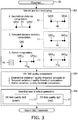
- FIG. 3 illustrates a flowchart 80 representative of an EMF QA method of the present invention.
- a stage S82 of flowchart 80 encompasses EM sensor monitoring module 75 ( FIG. 1 ) executing one or more of four sensed position monitoring modes.
- the position monitoring by module 75 for all modes is executed relative to a coordinate system associated with an emission of the EMF including, but not limited, an internal coordinate system 14 of EMF generator 10 as shown in FIGS. 1 and 2 and a reference coordinate system of reference electromagnetic sensor 50 as known in the art.
- module 76 knows a physical distance PD between a pair of electromagnetic sensors QAS1 and QAS2 (e.g., sensor pair 11, sensor pair 21, sensor pair 31 or sensor pair 41 of FIG. 1 ).
- module 75 monitor a sensed position of each electromagnetic sensors QAS1 and QAS2 within FOV 12 of the EMF. Based on the sensed positions by module 75, module 76 computes a geometrical distance GD between electromagnetic sensors QAS1 and QAS2 for quality assessment purposes subsequently described herein during a stage S84 of flowchart 80.
- geometrical distance GD may be computed as a magnitude of a vector extending between electromagnetic sensors QAS1 and QAS2.
- Temporal Positioning Mode (exemplarily shown in stage S82) .
- module 75 monitors a sensed position of a single electromagnetic sensor QAS at two or more discrete time instances 1 tillN corresponding to electromagnetic sensor QAS being stationary within FOV 12 of the EMF.
- QA electromagnetic sensors 11R/11L, 21R/21L, 31R/31L and 50 of FIG. 2 being stationary within FOV 12 of the EMF.
- module 75 monitors a sensed position of QA electromagnetic sensor QAS within FOV 12 of the EMF at a time t1 and a time t2. Based on the temporal position sensing, module 76 computes a temporal position variation TPV of electromagnetic sensor QAS for quality assessment purposes subsequently described herein during stage S84 of flowchart 80.
- temporal position variation TPV may be computed as a magnitude of a vector, if any, extending between the sensed temporal positions of electromagnetic sensor QAS.
- Encoded Translation Mode (exemplarily shown in stage S82) .
- module 75 monitors a sensed translational movement of electromagnetic sensor QAS of ultrasound probe 20 ( FIG. 2 ) controlled by ultrasound stepper 30 ( FIG. 2 ), while encoder 61 ( FIG. 2 ) concurrently measures the translational movement of electromagnetic sensor QAS of ultrasound probe 20 controlled by ultrasound stepper 30.
- encoder 61 measures a translation distance TD M of electromagnetic sensor QAS at a beginning time t1 and an ending time t2.
- module 75 monitors a sensed positioning of electromagnetic sensor QAS within FOV 12 of the EMF at beginning time t1 and ending time t2.
- module 76 computes a sensed translation distance TD S of electromagnetic sensor QAS within FOV 12 of the EMF and further computes of absolute motion variation between translation distance TD M and sensed translation distance TD S for quality assessment purposes subsequently described herein during stage S84 of flowchart 80.
- sensed translation distance TD S may be computed as a magnitude of a vector, if any, extending between the sensed translation positions of electromagnetic sensor QAS.
- Encoded Rotation Mode (not exemplarily shown in stage S82) .
- module 75 monitors a sensed rotational movement of electromagnetic sensor QAS of ultrasound probe 20 controlled by ultrasound stepper 30, while encoder 61 concurrently measures the rotational movement of electromagnetic sensor QAS of ultrasound probe 20 controlled by ultrasound stepper 30.
- encoder 61 measures a rotational distance of electromagnetic sensor QAS at a beginning time t1 and an ending time t2.
- module 75 monitors a sensed positioning of electromagnetic sensor QAS within FOV 12 of the EMF at beginning time t1 and ending time t2.
- module 76 computes a sensed rotational distance of electromagnetic sensor QAS within FOV 12 of the EMF and further computes an absolute motion variation between the measured rotational distance and the sensed rotational distance for quality assessment purposes subsequently described herein during stage S84 of flowchart 80.
- the sensed rotational distance may be computed as a magnitude of a vector, if any, extending between the sensed rotation positions of electromagnetic sensor QAS.
- a stage S84 of flowchart 80 encompasses quality assessment module 76 ( FIG. 1 ) assessing a quality of EMF field 12 ( FIG. 1 ) and a stage S85 of flowchart 80 generating a graphical user interface ("GUI") 77 illustrative of the assessed quality of EMF field 12.
- GUI graphical user interface
- Module 76 computes an absolute error differential between computed geometrical distance GD and known physical distance PD. Module 76 deems EMF field 12 as being reliable for tracking purposes if the error differential is less than or equal to a quality threshold QT. Otherwise, module 76 deems EMF field 12 as being unreliable for tracking purposes.
- Module 76 deems EMF field 12 as being reliable for tracking purposes if temporal position variation TPV is less than or equal to quality threshold QT. Otherwise, module 76 deems EMF field 12 as being unreliable for tracking purposes.
- Module 76 deems EMF field 12 as being reliable for tracking purposes if an absolute motion variation between measured translation distance TD M and sensed translation distance TD S is less than or equal to quality threshold QT. Otherwise, module 76 deems EMF field 12 as being unreliable for tracking purposes.
- Module 76 deems EMF field 12 as being reliable for tracking purposes if an absolute motion variation between measured rotation distance RD M and sensed rotation distance RD S is less than or equal to quality threshold QT. Otherwise, module 76 deems EMF field 12 as being unreliable for tracking purposes.
- a numerical value for quality threshold QT is derived from testing and training set of sensed data and is therefore dependent upon a particular clinical set-up arrangement.
- Modules 75 and 76 will sequentially repeat stages S82-S86 as needed during a calibration, quality assurance and/or EM guidance of the clinical set-up. More particular to EM guidance, referring back to FIG. 1 , GUI 77 will be displayed in conjunction with an ultrasound ("US") image 78 generated by ultrasound probe 20 whereby the reliability of tracking an interventional tool within ultrasound image 78 is communicated in real-time to an operator.
- US ultrasound
- FIGS. 1-3 from the description of the exemplary embodiments of a mounting arm and intervention workstation of the present invention, those having ordinary skill in the art will appreciate numerous benefits of the present invention including, but not limited to, a facilitation of a reliable positioning of a EMF generator in any EM-guided interventional procedure.
- FIGS. 1-3 may be implemented in various combinations of electronic components/circuitry, hardware, executable software and executable firmware, particularly as application modules of a quality assurance controller as described herein, and provide functions which may be combined in a single element or multiple elements.
- the functions of the various features, elements, components, etc. shown/illustrated/depicted in the FIGS. 1-3 can be provided through the use of dedicated hardware as well as hardware capable of executing software in association with appropriate software.
- processor When provided by a processor, the functions can be provided by a single dedicated processor, by a single shared processor, or by a plurality of individual processors, some of which can be shared and/or multiplexed.
- explicit use of the term "processor” should not be construed to refer exclusively to hardware capable of executing software, and can implicitly include, without limitation, digital signal processor ("DSP") hardware, memory (e.g., read only memory (“ROM”) for storing software, random access memory (“RAM”), non-volatile storage, etc.) and virtually any means and/or machine (including hardware, software, firmware, circuitry, combinations thereof, etc.) which is capable of (and/or configurable) to perform and/or control a process.
- DSP digital signal processor
- any flow charts, flow diagrams and the like can represent various processes which can be substantially represented in computer readable storage media and so executed by a computer, processor or other device with processing capabilities, whether or not such computer or processor is explicitly shown.
- exemplary embodiments of the present invention can take the form of a computer program product or application module accessible from a computer-usable and/or computer-readable storage medium providing program code and/or instructions for use by or in connection with, e.g., a computer or any instruction execution system.
- a computer-usable or computer readable storage medium can be any apparatus that can, e.g., include, store, communicate, propagate or transport the program for use by or in connection with the instruction execution system, apparatus or device.
- Such exemplary medium can be, e.g., an electronic, magnetic, optical, electromagnetic, infrared or semiconductor system (or apparatus or device) or a propagation medium.
- Examples of a computer-readable medium include, e.g., a semiconductor or solid state memory, magnetic tape, a removable computer diskette, a random access memory (RAM), a read-only memory (ROM), flash (drive), a rigid magnetic disk and an optical disk.
- Current examples of optical disks include compact disk - read only memory (CD-ROM), compact disk - read/write (CD-R/W) and DVD.
Landscapes
- Health & Medical Sciences (AREA)
- Engineering & Computer Science (AREA)
- Life Sciences & Earth Sciences (AREA)
- Biomedical Technology (AREA)
- Veterinary Medicine (AREA)
- Animal Behavior & Ethology (AREA)
- General Health & Medical Sciences (AREA)
- Public Health (AREA)
- Pathology (AREA)
- Physics & Mathematics (AREA)
- Surgery (AREA)
- Nuclear Medicine, Radiotherapy & Molecular Imaging (AREA)
- Molecular Biology (AREA)
- Medical Informatics (AREA)
- Heart & Thoracic Surgery (AREA)
- Biophysics (AREA)
- Radiology & Medical Imaging (AREA)
- Signal Processing (AREA)
- Artificial Intelligence (AREA)
- Psychiatry (AREA)
- Physiology (AREA)
- Computer Vision & Pattern Recognition (AREA)
- Human Computer Interaction (AREA)
- Electromagnetism (AREA)
- General Physics & Mathematics (AREA)
- Robotics (AREA)
- Ultra Sonic Daignosis Equipment (AREA)
- Radiation-Therapy Devices (AREA)
Applications Claiming Priority (2)
| Application Number | Priority Date | Filing Date | Title |
|---|---|---|---|
| US201462096580P | 2014-12-24 | 2014-12-24 | |
| PCT/IB2015/059458 WO2016103089A1 (en) | 2014-12-24 | 2015-12-09 | Tracking quality control for electromagnetic guidance |
Publications (2)
| Publication Number | Publication Date |
|---|---|
| EP3237064A1 EP3237064A1 (en) | 2017-11-01 |
| EP3237064B1 true EP3237064B1 (en) | 2019-09-11 |
Family
ID=55024189
Family Applications (1)
| Application Number | Title | Priority Date | Filing Date |
|---|---|---|---|
| EP15816533.2A Active EP3237064B1 (en) | 2014-12-24 | 2015-12-09 | Tracking quality control for electromagnetic guidance |
Country Status (5)
| Country | Link |
|---|---|
| US (1) | US10816585B2 (zh) |
| EP (1) | EP3237064B1 (zh) |
| JP (1) | JP6827931B2 (zh) |
| CN (1) | CN107106031B (zh) |
| WO (1) | WO2016103089A1 (zh) |
Families Citing this family (8)
| Publication number | Priority date | Publication date | Assignee | Title |
|---|---|---|---|---|
| US10499999B2 (en) | 2014-10-09 | 2019-12-10 | Auris Health, Inc. | Systems and methods for aligning an elongate member with an access site |
| WO2019005699A1 (en) * | 2017-06-28 | 2019-01-03 | Auris Health, Inc. | ELECTROMAGNETIC FIELD GENERATOR ALIGNMENT |
| EP3644886A4 (en) | 2017-06-28 | 2021-03-24 | Auris Health, Inc. | ELECTROMAGNETIC DISTORTION DETECTION |
| US10464209B2 (en) | 2017-10-05 | 2019-11-05 | Auris Health, Inc. | Robotic system with indication of boundary for robotic arm |
| US10016900B1 (en) | 2017-10-10 | 2018-07-10 | Auris Health, Inc. | Surgical robotic arm admittance control |
| EP4025921A4 (en) | 2019-09-03 | 2023-09-06 | Auris Health, Inc. | ELECTROMAGNETIC DISTORTION DETECTION AND COMPENSATION |
| US11614474B2 (en) * | 2020-07-24 | 2023-03-28 | Dkl International, Inc. | Remote detection of animate entities |
| CN112767505B (zh) * | 2020-12-31 | 2023-12-22 | 深圳市联影高端医疗装备创新研究院 | 图像处理方法、训练方法、装置、电子终端及存储介质 |
Citations (1)
| Publication number | Priority date | Publication date | Assignee | Title |
|---|---|---|---|---|
| WO2011110966A2 (en) * | 2010-03-11 | 2011-09-15 | Koninklijke Philips Electronics N.V. | Method and system for characterizing and visualizing electromagnetic tracking errors |
Family Cites Families (13)
| Publication number | Priority date | Publication date | Assignee | Title |
|---|---|---|---|---|
| US6147480A (en) * | 1997-10-23 | 2000-11-14 | Biosense, Inc. | Detection of metal disturbance |
| US20050107687A1 (en) * | 2003-11-14 | 2005-05-19 | Anderson Peter T. | System and method for distortion reduction in an electromagnetic tracker |
| US7805269B2 (en) * | 2004-11-12 | 2010-09-28 | Philips Electronics Ltd | Device and method for ensuring the accuracy of a tracking device in a volume |
| US9733336B2 (en) * | 2006-03-31 | 2017-08-15 | Koninklijke Philips N.V. | System for local error compensation in electromagnetic tracking systems |
| US7688064B2 (en) * | 2006-07-11 | 2010-03-30 | Biosense Webster Inc. | Probe for assessment of metal distortion |
| US8326402B2 (en) * | 2006-08-21 | 2012-12-04 | Biosense Webster, Inc. | Distortion-immune position tracking using frequency extrapolation |
| EP2191768A4 (en) * | 2007-09-07 | 2016-08-31 | Olympus Corp | POSITION SENSOR, MEDICAL DEVICE GUIDING SYSTEM, POSITION DETECTING METHOD, AND MEDICAL DEVICE GUIDING METHOD |
| US7603251B1 (en) * | 2008-06-23 | 2009-10-13 | The United States Of America As Represented By The Secretary Of The Navy | Magnetic anomaly sensing system for detection, localization and classification of a magnetic object in a cluttered field of magnetic anomalies |
| US10850126B2 (en) * | 2010-06-30 | 2020-12-01 | Koninklijke Philips N.V. | System and method for guided adaptive brachytherapy |
| CN103987337B (zh) | 2011-12-13 | 2017-05-17 | 皇家飞利浦有限公司 | 用于em跟踪的补偿、检测和误差校正的畸变指纹分析 |
| US10113889B2 (en) | 2012-03-29 | 2018-10-30 | Koninklijke Philips N.V. | Quality assurance system and method for navigation-assisted procedures |
| US9504445B2 (en) * | 2013-02-28 | 2016-11-29 | General Electric Company | Ultrasound imaging system and method for drift compensation |
| WO2015145300A2 (en) * | 2014-03-24 | 2015-10-01 | Koninklijke Philips N.V. | Quality assurance and data coordination for electromagnetic tracking systems |
-
2015
- 2015-12-09 WO PCT/IB2015/059458 patent/WO2016103089A1/en active Application Filing
- 2015-12-09 EP EP15816533.2A patent/EP3237064B1/en active Active
- 2015-12-09 JP JP2017533573A patent/JP6827931B2/ja active Active
- 2015-12-09 CN CN201580070659.7A patent/CN107106031B/zh active Active
- 2015-12-09 US US15/537,894 patent/US10816585B2/en active Active
Patent Citations (1)
| Publication number | Priority date | Publication date | Assignee | Title |
|---|---|---|---|---|
| WO2011110966A2 (en) * | 2010-03-11 | 2011-09-15 | Koninklijke Philips Electronics N.V. | Method and system for characterizing and visualizing electromagnetic tracking errors |
Also Published As
| Publication number | Publication date |
|---|---|
| JP6827931B2 (ja) | 2021-02-10 |
| EP3237064A1 (en) | 2017-11-01 |
| WO2016103089A1 (en) | 2016-06-30 |
| US10816585B2 (en) | 2020-10-27 |
| CN107106031A (zh) | 2017-08-29 |
| CN107106031B (zh) | 2020-09-01 |
| JP2018500996A (ja) | 2018-01-18 |
| US20170363669A1 (en) | 2017-12-21 |
Similar Documents
| Publication | Publication Date | Title |
|---|---|---|
| EP3237064B1 (en) | Tracking quality control for electromagnetic guidance | |
| US11819285B2 (en) | Magnetic interference detection systems and methods | |
| US9165114B2 (en) | Method and system for characterizing and visualizing electromagnetic tracking errors | |
| EP1545365B1 (en) | Medical device positioning system | |
| CN107106126B (zh) | 针对靶活检的针轨迹预测 | |
| CN108601578B (zh) | 超声探头的光学和惯性位置跟踪的设备内融合 | |
| US10786310B2 (en) | Quality assurance and data coordination for electromagnetic tracking systems | |
| US11259774B2 (en) | Registration of optical shape sensing tool | |
| CN107106240B (zh) | 显示线性仪器相对于3d医学图像导航后的位置和取向的方法和系统 | |
| US7789562B2 (en) | Calibration of a multi-plane X-ray unit | |
| JP2010519635A (ja) | 医学的画像形成のためのポインティングデバイス | |
| JP2018537301A (ja) | レーザを使用したカメラシステムに対するロボットアームの自動較正 | |
| CA2883162C (en) | Calibration jig for a flat location pad | |
| US9351800B2 (en) | Hybrid tracking system utilizing combined LED and magnetoresistance sensors | |
| US20160157887A1 (en) | Apparatus For Generating Needle Insertion Path For Interventional Robot | |
| US11317823B2 (en) | Detection of electromagnetic field interference | |
| US20230263577A1 (en) | Automatic ablation antenna segmentation from ct image | |
| US10953242B2 (en) | Guiding tracked shape reconstruction for interventional procedures | |
| WO2013057641A1 (en) | Cathlab planning tool | |
| WO2016092461A1 (en) | Positioning electromagnetic field generators for interventional procedures |
Legal Events
| Date | Code | Title | Description |
|---|---|---|---|
| STAA | Information on the status of an ep patent application or granted ep patent |
Free format text: STATUS: THE INTERNATIONAL PUBLICATION HAS BEEN MADE |
|
| PUAI | Public reference made under article 153(3) epc to a published international application that has entered the european phase |
Free format text: ORIGINAL CODE: 0009012 |
|
| STAA | Information on the status of an ep patent application or granted ep patent |
Free format text: STATUS: REQUEST FOR EXAMINATION WAS MADE |
|
| 17P | Request for examination filed |
Effective date: 20170724 |
|
| AK | Designated contracting states |
Kind code of ref document: A1 Designated state(s): AL AT BE BG CH CY CZ DE DK EE ES FI FR GB GR HR HU IE IS IT LI LT LU LV MC MK MT NL NO PL PT RO RS SE SI SK SM TR |
|
| AX | Request for extension of the european patent |
Extension state: BA ME |
|
| DAV | Request for validation of the european patent (deleted) | ||
| DAX | Request for extension of the european patent (deleted) | ||
| STAA | Information on the status of an ep patent application or granted ep patent |
Free format text: STATUS: EXAMINATION IS IN PROGRESS |
|
| 17Q | First examination report despatched |
Effective date: 20180619 |
|
| RIC1 | Information provided on ipc code assigned before grant |
Ipc: A61B 5/06 20060101ALI20190123BHEP Ipc: G01R 29/08 20060101ALI20190123BHEP Ipc: A61B 17/00 20060101ALN20190123BHEP Ipc: A61B 10/02 20060101ALN20190123BHEP Ipc: A61B 5/00 20060101ALI20190123BHEP Ipc: A61N 5/10 20060101AFI20190123BHEP Ipc: A61B 34/20 20160101ALI20190123BHEP |
|
| GRAP | Despatch of communication of intention to grant a patent |
Free format text: ORIGINAL CODE: EPIDOSNIGR1 |
|
| STAA | Information on the status of an ep patent application or granted ep patent |
Free format text: STATUS: GRANT OF PATENT IS INTENDED |
|
| RIC1 | Information provided on ipc code assigned before grant |
Ipc: A61B 5/06 20060101ALI20190322BHEP Ipc: G01R 29/08 20060101ALI20190322BHEP Ipc: A61B 5/00 20060101ALI20190322BHEP Ipc: A61N 5/10 20060101AFI20190322BHEP Ipc: A61B 34/20 20160101ALI20190322BHEP Ipc: A61B 17/00 20060101ALN20190322BHEP Ipc: A61B 10/02 20060101ALN20190322BHEP |
|
| INTG | Intention to grant announced |
Effective date: 20190416 |
|
| GRAS | Grant fee paid |
Free format text: ORIGINAL CODE: EPIDOSNIGR3 |
|
| GRAA | (expected) grant |
Free format text: ORIGINAL CODE: 0009210 |
|
| STAA | Information on the status of an ep patent application or granted ep patent |
Free format text: STATUS: THE PATENT HAS BEEN GRANTED |
|
| AK | Designated contracting states |
Kind code of ref document: B1 Designated state(s): AL AT BE BG CH CY CZ DE DK EE ES FI FR GB GR HR HU IE IS IT LI LT LU LV MC MK MT NL NO PL PT RO RS SE SI SK SM TR |
|
| REG | Reference to a national code |
Ref country code: GB Ref legal event code: FG4D |
|
| REG | Reference to a national code |
Ref country code: CH Ref legal event code: EP |
|
| REG | Reference to a national code |
Ref country code: AT Ref legal event code: REF Ref document number: 1177691 Country of ref document: AT Kind code of ref document: T Effective date: 20190915 |
|
| REG | Reference to a national code |
Ref country code: DE Ref legal event code: R096 Ref document number: 602015037929 Country of ref document: DE Ref country code: IE Ref legal event code: FG4D |
|
| REG | Reference to a national code |
Ref country code: NL Ref legal event code: MP Effective date: 20190911 |
|
| REG | Reference to a national code |
Ref country code: LT Ref legal event code: MG4D |
|
| PG25 | Lapsed in a contracting state [announced via postgrant information from national office to epo] |
Ref country code: FI Free format text: LAPSE BECAUSE OF FAILURE TO SUBMIT A TRANSLATION OF THE DESCRIPTION OR TO PAY THE FEE WITHIN THE PRESCRIBED TIME-LIMIT Effective date: 20190911 Ref country code: LT Free format text: LAPSE BECAUSE OF FAILURE TO SUBMIT A TRANSLATION OF THE DESCRIPTION OR TO PAY THE FEE WITHIN THE PRESCRIBED TIME-LIMIT Effective date: 20190911 Ref country code: SE Free format text: LAPSE BECAUSE OF FAILURE TO SUBMIT A TRANSLATION OF THE DESCRIPTION OR TO PAY THE FEE WITHIN THE PRESCRIBED TIME-LIMIT Effective date: 20190911 Ref country code: HR Free format text: LAPSE BECAUSE OF FAILURE TO SUBMIT A TRANSLATION OF THE DESCRIPTION OR TO PAY THE FEE WITHIN THE PRESCRIBED TIME-LIMIT Effective date: 20190911 Ref country code: BG Free format text: LAPSE BECAUSE OF FAILURE TO SUBMIT A TRANSLATION OF THE DESCRIPTION OR TO PAY THE FEE WITHIN THE PRESCRIBED TIME-LIMIT Effective date: 20191211 Ref country code: NO Free format text: LAPSE BECAUSE OF FAILURE TO SUBMIT A TRANSLATION OF THE DESCRIPTION OR TO PAY THE FEE WITHIN THE PRESCRIBED TIME-LIMIT Effective date: 20191211 |
|
| PG25 | Lapsed in a contracting state [announced via postgrant information from national office to epo] |
Ref country code: LV Free format text: LAPSE BECAUSE OF FAILURE TO SUBMIT A TRANSLATION OF THE DESCRIPTION OR TO PAY THE FEE WITHIN THE PRESCRIBED TIME-LIMIT Effective date: 20190911 Ref country code: AL Free format text: LAPSE BECAUSE OF FAILURE TO SUBMIT A TRANSLATION OF THE DESCRIPTION OR TO PAY THE FEE WITHIN THE PRESCRIBED TIME-LIMIT Effective date: 20190911 Ref country code: GR Free format text: LAPSE BECAUSE OF FAILURE TO SUBMIT A TRANSLATION OF THE DESCRIPTION OR TO PAY THE FEE WITHIN THE PRESCRIBED TIME-LIMIT Effective date: 20191212 Ref country code: RS Free format text: LAPSE BECAUSE OF FAILURE TO SUBMIT A TRANSLATION OF THE DESCRIPTION OR TO PAY THE FEE WITHIN THE PRESCRIBED TIME-LIMIT Effective date: 20190911 |
|
| RAP2 | Party data changed (patent owner data changed or rights of a patent transferred) |
Owner name: KONINKLIJKE PHILIPS N.V. |
|
| REG | Reference to a national code |
Ref country code: AT Ref legal event code: MK05 Ref document number: 1177691 Country of ref document: AT Kind code of ref document: T Effective date: 20190911 |
|
| PG25 | Lapsed in a contracting state [announced via postgrant information from national office to epo] |
Ref country code: NL Free format text: LAPSE BECAUSE OF FAILURE TO SUBMIT A TRANSLATION OF THE DESCRIPTION OR TO PAY THE FEE WITHIN THE PRESCRIBED TIME-LIMIT Effective date: 20190911 Ref country code: AT Free format text: LAPSE BECAUSE OF FAILURE TO SUBMIT A TRANSLATION OF THE DESCRIPTION OR TO PAY THE FEE WITHIN THE PRESCRIBED TIME-LIMIT Effective date: 20190911 Ref country code: PL Free format text: LAPSE BECAUSE OF FAILURE TO SUBMIT A TRANSLATION OF THE DESCRIPTION OR TO PAY THE FEE WITHIN THE PRESCRIBED TIME-LIMIT Effective date: 20190911 Ref country code: EE Free format text: LAPSE BECAUSE OF FAILURE TO SUBMIT A TRANSLATION OF THE DESCRIPTION OR TO PAY THE FEE WITHIN THE PRESCRIBED TIME-LIMIT Effective date: 20190911 Ref country code: PT Free format text: LAPSE BECAUSE OF FAILURE TO SUBMIT A TRANSLATION OF THE DESCRIPTION OR TO PAY THE FEE WITHIN THE PRESCRIBED TIME-LIMIT Effective date: 20200113 Ref country code: RO Free format text: LAPSE BECAUSE OF FAILURE TO SUBMIT A TRANSLATION OF THE DESCRIPTION OR TO PAY THE FEE WITHIN THE PRESCRIBED TIME-LIMIT Effective date: 20190911 Ref country code: IT Free format text: LAPSE BECAUSE OF FAILURE TO SUBMIT A TRANSLATION OF THE DESCRIPTION OR TO PAY THE FEE WITHIN THE PRESCRIBED TIME-LIMIT Effective date: 20190911 |
|
| PG25 | Lapsed in a contracting state [announced via postgrant information from national office to epo] |
Ref country code: SM Free format text: LAPSE BECAUSE OF FAILURE TO SUBMIT A TRANSLATION OF THE DESCRIPTION OR TO PAY THE FEE WITHIN THE PRESCRIBED TIME-LIMIT Effective date: 20190911 Ref country code: SK Free format text: LAPSE BECAUSE OF FAILURE TO SUBMIT A TRANSLATION OF THE DESCRIPTION OR TO PAY THE FEE WITHIN THE PRESCRIBED TIME-LIMIT Effective date: 20190911 Ref country code: IS Free format text: LAPSE BECAUSE OF FAILURE TO SUBMIT A TRANSLATION OF THE DESCRIPTION OR TO PAY THE FEE WITHIN THE PRESCRIBED TIME-LIMIT Effective date: 20200224 Ref country code: CZ Free format text: LAPSE BECAUSE OF FAILURE TO SUBMIT A TRANSLATION OF THE DESCRIPTION OR TO PAY THE FEE WITHIN THE PRESCRIBED TIME-LIMIT Effective date: 20190911 |
|
| REG | Reference to a national code |
Ref country code: DE Ref legal event code: R097 Ref document number: 602015037929 Country of ref document: DE |
|
| PLBE | No opposition filed within time limit |
Free format text: ORIGINAL CODE: 0009261 |
|
| STAA | Information on the status of an ep patent application or granted ep patent |
Free format text: STATUS: NO OPPOSITION FILED WITHIN TIME LIMIT |
|
| PG2D | Information on lapse in contracting state deleted |
Ref country code: IS |
|
| PG25 | Lapsed in a contracting state [announced via postgrant information from national office to epo] |
Ref country code: DK Free format text: LAPSE BECAUSE OF FAILURE TO SUBMIT A TRANSLATION OF THE DESCRIPTION OR TO PAY THE FEE WITHIN THE PRESCRIBED TIME-LIMIT Effective date: 20190911 Ref country code: IS Free format text: LAPSE BECAUSE OF FAILURE TO SUBMIT A TRANSLATION OF THE DESCRIPTION OR TO PAY THE FEE WITHIN THE PRESCRIBED TIME-LIMIT Effective date: 20200112 |
|
| REG | Reference to a national code |
Ref country code: CH Ref legal event code: PL |
|
| 26N | No opposition filed |
Effective date: 20200615 |
|
| REG | Reference to a national code |
Ref country code: BE Ref legal event code: MM Effective date: 20191231 |
|
| PG25 | Lapsed in a contracting state [announced via postgrant information from national office to epo] |
Ref country code: SI Free format text: LAPSE BECAUSE OF FAILURE TO SUBMIT A TRANSLATION OF THE DESCRIPTION OR TO PAY THE FEE WITHIN THE PRESCRIBED TIME-LIMIT Effective date: 20190911 Ref country code: MC Free format text: LAPSE BECAUSE OF FAILURE TO SUBMIT A TRANSLATION OF THE DESCRIPTION OR TO PAY THE FEE WITHIN THE PRESCRIBED TIME-LIMIT Effective date: 20190911 |
|
| PG25 | Lapsed in a contracting state [announced via postgrant information from national office to epo] |
Ref country code: ES Free format text: LAPSE BECAUSE OF FAILURE TO SUBMIT A TRANSLATION OF THE DESCRIPTION OR TO PAY THE FEE WITHIN THE PRESCRIBED TIME-LIMIT Effective date: 20190911 Ref country code: LU Free format text: LAPSE BECAUSE OF NON-PAYMENT OF DUE FEES Effective date: 20191209 Ref country code: IE Free format text: LAPSE BECAUSE OF NON-PAYMENT OF DUE FEES Effective date: 20191209 |
|
| PG25 | Lapsed in a contracting state [announced via postgrant information from national office to epo] |
Ref country code: CH Free format text: LAPSE BECAUSE OF NON-PAYMENT OF DUE FEES Effective date: 20191231 Ref country code: BE Free format text: LAPSE BECAUSE OF NON-PAYMENT OF DUE FEES Effective date: 20191231 Ref country code: LI Free format text: LAPSE BECAUSE OF NON-PAYMENT OF DUE FEES Effective date: 20191231 |
|
| PG25 | Lapsed in a contracting state [announced via postgrant information from national office to epo] |
Ref country code: CY Free format text: LAPSE BECAUSE OF FAILURE TO SUBMIT A TRANSLATION OF THE DESCRIPTION OR TO PAY THE FEE WITHIN THE PRESCRIBED TIME-LIMIT Effective date: 20190911 |
|
| PG25 | Lapsed in a contracting state [announced via postgrant information from national office to epo] |
Ref country code: HU Free format text: LAPSE BECAUSE OF FAILURE TO SUBMIT A TRANSLATION OF THE DESCRIPTION OR TO PAY THE FEE WITHIN THE PRESCRIBED TIME-LIMIT; INVALID AB INITIO Effective date: 20151209 Ref country code: MT Free format text: LAPSE BECAUSE OF FAILURE TO SUBMIT A TRANSLATION OF THE DESCRIPTION OR TO PAY THE FEE WITHIN THE PRESCRIBED TIME-LIMIT Effective date: 20190911 |
|
| PG25 | Lapsed in a contracting state [announced via postgrant information from national office to epo] |
Ref country code: TR Free format text: LAPSE BECAUSE OF FAILURE TO SUBMIT A TRANSLATION OF THE DESCRIPTION OR TO PAY THE FEE WITHIN THE PRESCRIBED TIME-LIMIT Effective date: 20190911 |
|
| PG25 | Lapsed in a contracting state [announced via postgrant information from national office to epo] |
Ref country code: MK Free format text: LAPSE BECAUSE OF FAILURE TO SUBMIT A TRANSLATION OF THE DESCRIPTION OR TO PAY THE FEE WITHIN THE PRESCRIBED TIME-LIMIT Effective date: 20190911 |
|
| PGFP | Annual fee paid to national office [announced via postgrant information from national office to epo] |
Ref country code: GB Payment date: 20231219 Year of fee payment: 9 |
|
| PGFP | Annual fee paid to national office [announced via postgrant information from national office to epo] |
Ref country code: FR Payment date: 20231226 Year of fee payment: 9 |
|
| PGFP | Annual fee paid to national office [announced via postgrant information from national office to epo] |
Ref country code: DE Payment date: 20231227 Year of fee payment: 9 |