EP3236578A1 - Control of ultrasonic motor in surveying instrument - Google Patents
Control of ultrasonic motor in surveying instrument Download PDFInfo
- Publication number
- EP3236578A1 EP3236578A1 EP17167494.8A EP17167494A EP3236578A1 EP 3236578 A1 EP3236578 A1 EP 3236578A1 EP 17167494 A EP17167494 A EP 17167494A EP 3236578 A1 EP3236578 A1 EP 3236578A1
- Authority
- EP
- European Patent Office
- Prior art keywords
- drive signal
- rotation speed
- ultrasonic motor
- speed
- range
- Prior art date
- Legal status (The legal status is an assumption and is not a legal conclusion. Google has not performed a legal analysis and makes no representation as to the accuracy of the status listed.)
- Granted
Links
Images




Classifications
-
- H—ELECTRICITY
- H02—GENERATION; CONVERSION OR DISTRIBUTION OF ELECTRIC POWER
- H02N—ELECTRIC MACHINES NOT OTHERWISE PROVIDED FOR
- H02N2/00—Electric machines in general using piezoelectric effect, electrostriction or magnetostriction
- H02N2/10—Electric machines in general using piezoelectric effect, electrostriction or magnetostriction producing rotary motion, e.g. rotary motors
- H02N2/14—Drive circuits; Control arrangements or methods
- H02N2/142—Small signal circuits; Means for controlling position or derived quantities, e.g. speed, torque, starting, stopping, reversing
-
- G—PHYSICS
- G01—MEASURING; TESTING
- G01C—MEASURING DISTANCES, LEVELS OR BEARINGS; SURVEYING; NAVIGATION; GYROSCOPIC INSTRUMENTS; PHOTOGRAMMETRY OR VIDEOGRAMMETRY
- G01C15/00—Surveying instruments or accessories not provided for in groups G01C1/00 - G01C13/00
- G01C15/002—Active optical surveying means
-
- H—ELECTRICITY
- H02—GENERATION; CONVERSION OR DISTRIBUTION OF ELECTRIC POWER
- H02N—ELECTRIC MACHINES NOT OTHERWISE PROVIDED FOR
- H02N2/00—Electric machines in general using piezoelectric effect, electrostriction or magnetostriction
- H02N2/10—Electric machines in general using piezoelectric effect, electrostriction or magnetostriction producing rotary motion, e.g. rotary motors
- H02N2/16—Electric machines in general using piezoelectric effect, electrostriction or magnetostriction producing rotary motion, e.g. rotary motors using travelling waves, i.e. Rayleigh surface waves
- H02N2/163—Motors with ring stator
Definitions
- the present invention relates to a method for controlling an ultrasonic motor that drives a rotary shaft of a surveying instrument, and a surveying instrument for the same.
- a surveying instrument for example, a total station includes a telescope that collimates a measurement point, a bracket portion that supports the telescope rotatably in the vertical direction, and a base that supports the bracket portion rotatably in the horizontal direction.
- the telescope is driven by a vertical rotary motor provided on a vertical rotary shaft
- the bracket portion is driven by a horizontal rotary motor provided on a horizontal rotary shaft.
- Patent Document 1 discloses a surveying instrument adopting ultrasonic motors as the vertical rotary motor and the horizontal rotary motor.
- many surveying instruments In addition to a mode in which collimation is manually performed by an operator, many surveying instruments have an automatic collimation mode in which automatic rotation to a predetermined survey point is performed, and an automatic tracking mode in which a moving target is automatically tracked.
- Patent Document 1 Japanese Published Unexamined Patent Application No. 2014-137299
- an object of the present invention is to provide a method for controlling an ultrasonic motor to meet requirements for a rotation speed and a plurality of operation modes by setting a drive signal according to the rotation speed and the plurality of operation modes in a surveying instrument adopting the ultrasonic motor for a rotary shaft, and a surveying instrument for the same.
- a method for controlling an ultrasonic motor is a method for controlling an ultrasonic motor that drives a rotary shaft of a surveying instrument in response to a drive signal with a variable frequency, wherein the ultrasonic motor is controlled by a first drive signal in which a square wave is formed by applying and stopping the drive signal in control cycles, in a range of rotation speed of the rotary shaft from zero to a first rotation speed, the ultrasonic motor is controlled by a second drive signal in which rises or falls of the square wave are sloped in a range from the first rotation speed to a second rotation speed, the ultrasonic motor is controlled by a third drive signal in which rises and falls of the square wave are sloped in a range from the second rotation speed to a third rotation speed, and the ultrasonic motor is controlled by a fourth drive signal in which the drive signal is continuously applied in a range higher than the third rotation speed.
- control cycles and the frequencies of the first to fourth drive signals, acceleration periods as times of application of the drive signal in the first to third drive signals, and values of the slopes of the second and third drive signals are set for each of a plurality of operation modes of the surveying instrument.
- At least one of controls by the first to fourth drive signals is omitted.
- a surveying instrument includes a control unit that performs control by a first drive signal in which a square wave is formed by applying and stopping the drive signal in control cycles in a range of rotation speed of the rotary shaft from zero to a first rotation speed, performs control by a second drive signal in which rises or falls of the square wave are sloped in a range from the first rotation speed to a second rotation speed, performs control by a third drive signal in which rises and falls of the square wave are sloped in a range from the second rotation speed to a third rotation speed, and performs control by a fourth drive signal in which the drive signal is continuously applied in a range higher than the third rotation speed.
- the present invention provides a method for controlling an ultrasonic motor to meet requirements for a rotation speed and a plurality of operation modes by setting a drive signal according to the rotation speed and the plurality of operation modes in a surveying instrument adopting the ultrasonic motor for a rotary shaft, and a surveying instrument for the same.
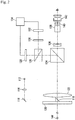
- Fig. 1 is a schematic longitudinal sectional view of a surveying instrument according to the present embodiment.
- the reference numeral 1 denotes a surveying instrument, and the surveying instrument 1 includes a base 4 provided on a leveling portion 3, a bracket portion 7 that rotates horizontally around a horizontal rotary shaft 6 on the base 4, and a telescope 9 that is supported by the bracket portion 7 and rotates vertically around a vertical rotary shaft 11.
- the bracket portion 7 houses a control unit 23.
- the surveying instrument 1 has three kinds of operation modes including a manual collimation mode in which a target is manually collimated, an automatic collimation mode in which automatic rotation to a predetermined survey point is performed, and an automatic tracking mode in which a moving target is automatically tracked.
- the telescope 9 houses a range-finding optical system for automatic collimation, a tracking optical system for automatic tracking, and a telescope optical system for manual collimation.
- Fig. 2 is a block diagram showing a configuration of an optical system of the surveying instrument 1, showing an example of a configuration of the optical system.
- a light source 112 is a laser diode that emits, for example, infrared light as range-finding light or tracking light. Light emitted from the light source 112 is transmitted through a light transmission lens 114 and enters a reflecting mirror 116, enters a light transmission prism 118, and is then transmitted toward a target 144 via a parallel glass 120, and reflected on the target 144.
- the reflected light enters a dichroic prism 124 via the parallel glass 120 and an object lens 122.
- a part of the reflected light is transmitted as collimation light through a focusing lens 136 and an erect prism 138 and forms an image on a focusing glass 140, and forms an image on an operator's retina via an eyepiece lens 142.
- the remainder of the reflected light enters a beam splitter 126 and is split.
- One of the split lights enters a first imaging element 128, and the other one of the split lights is transmitted through a wavelength filter 130 that removes infrared light, and then enters a second imaging element 132.
- the first imaging element 128 and the second imaging element 132 are image sensors, for example, CCD sensors or CMOS sensors. Images imaged by the imaging elements 128 and 132 are transmitted to an image processing device 134 and subjected to image processing. A scenery image including infrared light of the light source 112 is imaged by the first imaging element 128, and a scenery image from which infrared light of the light source 112 is removed is imaged by the second imaging element 132.
- the image processing device 134 obtains a difference between the image of the first imaging element 128 corresponding to a lighted image and the image of the second imaging element 132 corresponding to an unlighted image. By obtaining the difference, a center of the image of the target 144 can be obtained.
- Operation results of the image processing device 134 are transmitted to the control unit 23, and the control unit 23 detects, as a target position, a position at which a deviation between the center of the image of the target 144 and a center of a visual axis of the telescope falls within a predetermined value, and performs automatic collimation and automatic tracking.
- the control unit 23 detects, as a target position, a position at which a deviation between the center of the image of the target 144 and a center of a visual axis of the telescope falls within a predetermined value, and performs automatic collimation and automatic tracking.
- other conventionally known configurations may be adopted, and in particular, elements of the optical system described above may be altered based on knowledge of a person skilled in the art.
- an ultrasonic motor 5 for horizontal rotation is provided at a lower end portion of a horizontal rotary shaft 6, and an encoder 21 for horizontal angle detection is provided at an upper end portion.
- an ultrasonic motor 12 for vertical rotation is provided at one end portion of the vertical rotary shaft 11, and at the other end portion, an encoder 22 to detect a vertical angle is provided.
- the encoders 21 and 22 are absolute encoders each including a rotary disc, a slit, a light emitting diode, and an image sensor. Other than absolute encoders, incremental encoders may be used.
- Fig. 3 is a sectional perspective view of a portion including the ultrasonic motor 5 shown in Fig. 1 .
- the ultrasonic motor 5 includes, in a ring form, in order from the base portion 39, a piezoelectric ceramic 42 that generates vibration, a stator 43 that amplifies the vibration, a rotor 46 that interferes with the stator 43, and a wave washer 48 that presses the rotor 46 toward the stator 43 side.
- a Sin electrode and a Cos electrode are attached, and when a drive voltage is alternately applied to these electrodes, the piezoelectric ceramic 42 ultrasonically vibrates.
- a wavelike traveling wave is formed in the stator 43, and due to friction caused by pressing of the wave washer 48, the stator 43 and the rotor 46 rotate relative to each other.
- a motor case 25 is fixed to the base 4 and a rotor 46 is fixed to the motor case 25, so that when the stator 43 rotates, the horizontal rotary shaft 6 rotates integrally with the stator 43 via the base portion 39.
- a stator 43 is fixed to a motor case 25, and when a rotor 46 rotates, the vertical rotary shaft 11 rotates integrally with the rotor 46.
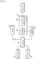
- Fig. 4 is a control block diagram of the surveying instrument 1.
- Block diagrams of vertical rotation and horizontal rotation are equivalent to each other, so that the horizontal rotation is shown, and description on the vertical rotation is omitted.
- the surveying instrument 1 includes a control unit 23, an encoder 21, a range-finding unit 61, a tracking unit 62, a clock signal oscillation unit 63, a drive circuit 73, and the ultrasonic motor 5.
- the control unit 23 consists of a microcontroller including a CPU, a ROM, and a RAM, etc., mounted on an integrated circuit. Software of the control unit 23 is changeable from an external personal computer that is not shown. The control unit 23 sequentially obtains a rotation speed of the rotary shaft 6 from an angle signal of the encoder 21. In addition, the control unit outputs a drive signal to the ultrasonic motor 5 via a drive circuit 73. Then, the control unit changes the waveform of the drive signal according to the rotation speed of the rotary shaft 6. A waveform of this drive signal is described in detail below.
- the range-finding unit 61 performs automatic collimation under control of the control unit 23 by irradiating a target with range-finding light by using the range-finding optical system and capturing a target by the light reflected thereon. In addition, when manual or automatic collimation is completed, the range-finding unit performs range-finding. Under control of the control unit 23, the tracking unit 62 irradiates a target with tracking light by using the tracking optical system and captures the target by the light reflected thereon, and automatically tracks the target when the target moves.
- the drive circuit 73 includes an FPGA (Field Programmable Gate Array) 731 and an analog circuit 732. Definition of an internal logic circuit of the FPGA 731 can be changed by the control unit 23 or an external device not shown.
- the FPGA 731 can generate a control signal at a variable drive frequency (drive signal frequency) and a variable amplitude, and can dynamically change the drive frequency and the amplitude.
- the analog circuit 732 includes a transformer, etc., and amplifies the control signal.
- the drive circuit 73 outputs the control signal from the FPGA 731 in response to a command from the control unit 23, and amplifies the control signal by the analog circuit 732 to generate two kinds of drive signals with different phases, and outputs these to the Sin electrode and the Cos electrode attached to the piezoelectric ceramic 42 of the ultrasonic motor 5.
- PLDs Programmable Logic Devices
- ASIC Application Specific Integrated Circuit
- the clock signal oscillation unit 63 outputs a clock signal to the control unit 23 and the FPGA 731.
- the control unit 23 controls light emission cycles of the encoder 21 based on the clock signal.
- the FPGA 731 controls an amplitude, a drive frequency, and control cycles of the drive signal, and controls, in a low-speed rotation range, a ratio of an acceleration period (time of application of the drive signal) and a deceleration period (time of stoppage of the drive signal) in each control cycle based on the clock signal.
- the low-speed rotation range means a speed range in which the ultrasonic motor cannot be continuously driven to rotate. This low-speed rotation range differs among individual ultrasonic motors according to their manufacturing states, and is defined in advance in the control unit 23 by investigating characteristics of the ultrasonic motor to be adopted.
- Fig. 5 is a control image diagram of the ultrasonic motor 5 according to the present embodiment.
- description about vertical rotation is also omitted, the same control as in the case of horizontal rotation is also performed for vertical rotation.
- the horizontal axis of Fig. 5 represents a rotation speed V of the rotary shaft 6.
- V0 the zero rotation speed
- V1 a first rotation speed
- this section is positioned as a run-up section, and the drive signal in the run-up section is formed into a square wave (first drive signal S1).
- the ultrasonic motor 5 causes an abnormal noise at rises and falls of the drive signal. Therefore, in a range from the first rotation speed V1 to a second rotation speed V2, by sloping either the rises or the falls of the square wave, both maintenance of the start of movement and the noise problem can be handled.
- This section is positioned as a small motion section, and the drive signal in the small motion section is formed into a square wave or triangle wave with a single slope (second drive signal S2).
- both of the rises and the falls of the square wave are sloped to reduce noise sounding.
- This section is positioned as an intermittent section, and the drive signal in the intermittent section is formed into a square wave or a triangle wave with double slopes (third drive signal S3).
- Values of the first rotation speed V1, the second rotation speed V2, and the third rotation speed V3 are set in advance in the control unit 23 according to individual characteristics of the adopted ultrasonic motor.
- “range from the first rotation speed V1 to the second rotation speed V2” means “range not less than the first rotation speed V1 and less than the second rotation speed V2.”
- Figs. 6 are waveform diagrams of the drive signals of the ultrasonic motor 5 in the respective sections described above, and Fig. 6(a) is a waveform diagram of the first drive signal S1, Fig. 6(b) is a waveform diagram of the second drive signal S2, Fig. 6(c) is a waveform diagram of the third drive signal S3, and Fig. 4(d) is a waveform diagram of the fourth drive signal S4.
- the horizontal axis represents time (t)
- the vertical axis represents an amplitude of the drive signal.
- the reference sign WT denotes a control cycle
- the reference sign RT denotes a time in which a rise of the signal is sloped (sloped upward)
- the reference sign FT denotes a time in which a fall of the signal is sloped (sloped downward)
- the reference sign OT denotes an acceleration time (acceleration period) in which the drive signal is applied in the low-speed rotation range.
- the upward slope RT and the downward slope FT are not limited to the linear functional lines shown in the figures, and may be curved slopes.
- the low-speed rotation range (less than the third rotation speed V3) into three sections of the run-up section, the small motion section, and the intermittent section, a proper measure according to the rotation speed can be taken to realize both smoothness of the rotation of the ultrasonic motor 5 and reduction in abnormal noise.
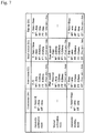
- Fig. 7 is a setting example of values for each operation mode of the ultrasonic motor 5.
- the values of the control cycle WT, the upward slope RT, the downward slope FT, and the acceleration period OT are set in advance. While fixing these control cycle WT, upward slope RT, downward slope FT, acceleration period OT, and amplitude of the drive signal, the control unit 23 performs speed adjustment during collimation or tracking by increasing or decreasing the drive frequency f.
- the drive frequency f a preferable value or a preferable varying range (minimum value and maximum value) is also preferably set for each operation mode.
- control cycle WT (a [ms]) of the tracking mode is set to be shorter than the control cycle WT (A [ms]) of the automatic collimation mode (a ⁇ A). Accordingly, noise sounding can be reduced in the automatic collimation mode, and feedback response can be made quicker and the tracking performance can be improved in the automatic tracking mode.
- control cycle WT of the manual collimation mode is set to be longer (2.5A) than the control cycle WT (A [ms]) of the automatic collimation mode, and the slope is correspondingly set longer (1.25A) to reduce noise.
- the rotary shaft In the manual collimation mode, the rotary shaft is largely rotated to the survey point and then finely rotated, so that the speed range to be used is from the first rotation speed V1 to the third rotation speed V3. Therefore, by using the waveform of the second drive signal S2 for low-speed rotation and the waveform of the third drive signal S3 for high-speed rotation, preferable control can be performed.
- the operation mode without using any of the first to fourth drive signals, only a drive signal in a section matching a rotation speed to be used is set, and setting of drive signals in other sections may be omitted.
- control cycle WT the upward slope RT, the downward slope FT, the acceleration period OT, and the drive frequency f of the drive signal for each operation mode of the surveying instrument 1
- control to meet requirements caused according to the operation mode can be performed.
- the surveying instrument 1 an operation mode to eliminate axial runout may be added.
- the ultrasonic motor 5 has a high holding force in a non-energizing time due to a frictional force between the stator 43 and the rotor 46, so that when motor operation stops, a problemmay occur in which the rotary shaft 6 cannot return from an axial runout position to an original position.
- the surveying instrument 1 may be provided with an operation mode in which a pair of a forward drive signal and a backward drive signal that apply equivalent rotation amounts are output to the ultrasonic motor 5 to return the rotary shaft 6 from an axial runout position to the original position after arriving at a rotation angle of a target position.
- a drive signal in a section corresponding to a speed range to be used for this operation mode is set, and a control cycle WT, an upward slope RT, a downward slope FT, an acceleration period OT, and a drive frequency f thereof are set.
Landscapes
- Physics & Mathematics (AREA)
- Engineering & Computer Science (AREA)
- General Physics & Mathematics (AREA)
- Radar, Positioning & Navigation (AREA)
- Remote Sensing (AREA)
- General Electrical Machinery Utilizing Piezoelectricity, Electrostriction Or Magnetostriction (AREA)
Abstract
Description
- The present invention relates to a method for controlling an ultrasonic motor that drives a rotary shaft of a surveying instrument, and a surveying instrument for the same.
- A surveying instrument, for example, a total station includes a telescope that collimates a measurement point, a bracket portion that supports the telescope rotatably in the vertical direction, and a base that supports the bracket portion rotatably in the horizontal direction. The telescope is driven by a vertical rotary motor provided on a vertical rotary shaft, and the bracket portion is driven by a horizontal rotary motor provided on a horizontal rotary shaft.
Patent Document 1 discloses a surveying instrument adopting ultrasonic motors as the vertical rotary motor and the horizontal rotary motor. - In addition to a mode in which collimation is manually performed by an operator, many surveying instruments have an automatic collimation mode in which automatic rotation to a predetermined survey point is performed, and an automatic tracking mode in which a moving target is automatically tracked.
- [Patent Document 1] Japanese Published Unexamined Patent Application No.
2014-137299 - In the automatic collimation mode, high-speed rotation to a predetermined survey point is desired. On the other hand, in the automatic tracking mode, to track a target that an operator carries, low-speed rotation at approximately 5 [°/s] is necessary. In the manual collimation mode, fine adjustment after large rotation to a survey point is desired. Thus, a surveying instrument has a problem in which required control differs depending on an operation mode.
- It is difficult for an ultrasonic motor to rotate at a low speed during continuous driving, and at the time of low-speed rotation, the speed is controlled by intermittent driving in which a drive signal is applied/stopped. However, when intermittent driving is performed, an abnormal noise occurs at rises and falls of the drive signal. Therefore, there is a problem in which during low-speed rotation, an operator is bothered by a tradeoff relationship between whether to make larger the signal waveform by considering rotation smoothness or whether to make smaller the signal waveform to reduce the noise.
- In order to solve the above-described problem, an object of the present invention is to provide a method for controlling an ultrasonic motor to meet requirements for a rotation speed and a plurality of operation modes by setting a drive signal according to the rotation speed and the plurality of operation modes in a surveying instrument adopting the ultrasonic motor for a rotary shaft, and a surveying instrument for the same.
- In order to solve the above-described problems, a method for controlling an ultrasonic motor according to an aspect of the present invention is a method for controlling an ultrasonic motor that drives a rotary shaft of a surveying instrument in response to a drive signal with a variable frequency, wherein the ultrasonic motor is controlled by a first drive signal in which a square wave is formed by applying and stopping the drive signal in control cycles, in a range of rotation speed of the rotary shaft from zero to a first rotation speed, the ultrasonic motor is controlled by a second drive signal in which rises or falls of the square wave are sloped in a range from the first rotation speed to a second rotation speed, the ultrasonic motor is controlled by a third drive signal in which rises and falls of the square wave are sloped in a range from the second rotation speed to a third rotation speed, and the ultrasonic motor is controlled by a fourth drive signal in which the drive signal is continuously applied in a range higher than the third rotation speed.
- In the aspect described above, it is also preferable that the control cycles and the frequencies of the first to fourth drive signals, acceleration periods as times of application of the drive signal in the first to third drive signals, and values of the slopes of the second and third drive signals, are set for each of a plurality of operation modes of the surveying instrument.
- In the aspect described above, it is also preferable that in at least one of the operation modes, at least one of controls by the first to fourth drive signals is omitted.
- In order to solve the above-described problems, a surveying instrument according to an aspect of the present invention includes a control unit that performs control by a first drive signal in which a square wave is formed by applying and stopping the drive signal in control cycles in a range of rotation speed of the rotary shaft from zero to a first rotation speed, performs control by a second drive signal in which rises or falls of the square wave are sloped in a range from the first rotation speed to a second rotation speed, performs control by a third drive signal in which rises and falls of the square wave are sloped in a range from the second rotation speed to a third rotation speed, and performs control by a fourth drive signal in which the drive signal is continuously applied in a range higher than the third rotation speed.
- The present invention provides a method for controlling an ultrasonic motor to meet requirements for a rotation speed and a plurality of operation modes by setting a drive signal according to the rotation speed and the plurality of operation modes in a surveying instrument adopting the ultrasonic motor for a rotary shaft, and a surveying instrument for the same.
-
-
Fig. 1 is a schematic longitudinal sectional view of a surveying instrument according to the present embodiment. -
Fig. 2 is a block diagram showing a configuration of an optical system of the surveying instrument according to the present embodiment. -
Fig. 3 is a sectional perspective view of a portion including an ultrasonic motor according to the present embodiment. -
Fig. 4 is a control block diagram of the surveying instrument according to the present embodiment. -
Fig. 5 is a control image diagram of the ultrasonic motor according to the present embodiment. -
Figs. 6 are waveform diagrams of drive signals of the ultrasonic motor according to the present embodiment,Fig. 6 (a) is a waveform diagram of a first drive signal,Fig. 6(b) is a waveform diagram of a second drive signal,Fig. 6(c) is a waveform diagram of a third drive signal, andFig. 6(d) is a waveform diagram of a fourth drive signal. -
Fig. 7 is a setting example of values for each operation mode of the ultrasonic motor according to the present embodiment. - Next, a preferred embodiment of the present invention is described with reference to the drawings.
-
Fig. 1 is a schematic longitudinal sectional view of a surveying instrument according to the present embodiment. Thereference numeral 1 denotes a surveying instrument, and thesurveying instrument 1 includes abase 4 provided on aleveling portion 3, a bracket portion 7 that rotates horizontally around a horizontalrotary shaft 6 on thebase 4, and a telescope 9 that is supported by the bracket portion 7 and rotates vertically around a verticalrotary shaft 11. The bracket portion 7 houses acontrol unit 23. Thesurveying instrument 1 has three kinds of operation modes including a manual collimation mode in which a target is manually collimated, an automatic collimation mode in which automatic rotation to a predetermined survey point is performed, and an automatic tracking mode in which a moving target is automatically tracked. - The telescope 9 houses a range-finding optical system for automatic collimation, a tracking optical system for automatic tracking, and a telescope optical system for manual collimation.
Fig. 2 is a block diagram showing a configuration of an optical system of thesurveying instrument 1, showing an example of a configuration of the optical system. Alight source 112 is a laser diode that emits, for example, infrared light as range-finding light or tracking light. Light emitted from thelight source 112 is transmitted through alight transmission lens 114 and enters a reflectingmirror 116, enters alight transmission prism 118, and is then transmitted toward atarget 144 via aparallel glass 120, and reflected on thetarget 144. The reflected light enters adichroic prism 124 via theparallel glass 120 and anobject lens 122. A part of the reflected light is transmitted as collimation light through a focusinglens 136 and anerect prism 138 and forms an image on a focusingglass 140, and forms an image on an operator's retina via aneyepiece lens 142. The remainder of the reflected light enters abeam splitter 126 and is split. One of the split lights enters afirst imaging element 128, and the other one of the split lights is transmitted through awavelength filter 130 that removes infrared light, and then enters asecond imaging element 132. - The
first imaging element 128 and thesecond imaging element 132 are image sensors, for example, CCD sensors or CMOS sensors. Images imaged by theimaging elements image processing device 134 and subjected to image processing. A scenery image including infrared light of thelight source 112 is imaged by thefirst imaging element 128, and a scenery image from which infrared light of thelight source 112 is removed is imaged by thesecond imaging element 132. Theimage processing device 134 obtains a difference between the image of thefirst imaging element 128 corresponding to a lighted image and the image of thesecond imaging element 132 corresponding to an unlighted image. By obtaining the difference, a center of the image of thetarget 144 can be obtained. Operation results of theimage processing device 134 are transmitted to thecontrol unit 23, and thecontrol unit 23 detects, as a target position, a position at which a deviation between the center of the image of thetarget 144 and a center of a visual axis of the telescope falls within a predetermined value, and performs automatic collimation and automatic tracking. For the optical system described above, other conventionally known configurations may be adopted, and in particular, elements of the optical system described above may be altered based on knowledge of a person skilled in the art. - As shown in
Fig. 1 , anultrasonic motor 5 for horizontal rotation is provided at a lower end portion of a horizontalrotary shaft 6, and anencoder 21 for horizontal angle detection is provided at an upper end portion. At one end portion of the verticalrotary shaft 11, anultrasonic motor 12 for vertical rotation is provided, and at the other end portion, anencoder 22 to detect a vertical angle is provided. Theencoders -
Fig. 3 is a sectional perspective view of a portion including theultrasonic motor 5 shown inFig. 1 . Concerning configurations of theultrasonic motors ultrasonic motor 5 includes, in a ring form, in order from thebase portion 39, a piezoelectric ceramic 42 that generates vibration, astator 43 that amplifies the vibration, arotor 46 that interferes with thestator 43, and awave washer 48 that presses therotor 46 toward thestator 43 side. To the piezoelectric ceramic 42, a Sin electrode and a Cos electrode are attached, and when a drive voltage is alternately applied to these electrodes, the piezoelectric ceramic 42 ultrasonically vibrates. When the piezoelectric ceramic 42 vibrates, a wavelike traveling wave is formed in thestator 43, and due to friction caused by pressing of thewave washer 48, thestator 43 and therotor 46 rotate relative to each other. As shown inFig. 1 , in the horizontalultrasonic motor 5, amotor case 25 is fixed to thebase 4 and arotor 46 is fixed to themotor case 25, so that when thestator 43 rotates, the horizontalrotary shaft 6 rotates integrally with thestator 43 via thebase portion 39. In the verticalultrasonic motor 12, astator 43 is fixed to amotor case 25, and when arotor 46 rotates, the verticalrotary shaft 11 rotates integrally with therotor 46. -
Fig. 4 is a control block diagram of the surveyinginstrument 1. Block diagrams of vertical rotation and horizontal rotation are equivalent to each other, so that the horizontal rotation is shown, and description on the vertical rotation is omitted. The surveyinginstrument 1 includes acontrol unit 23, anencoder 21, a range-findingunit 61, atracking unit 62, a clocksignal oscillation unit 63, adrive circuit 73, and theultrasonic motor 5. - The
control unit 23 consists of a microcontroller including a CPU, a ROM, and a RAM, etc., mounted on an integrated circuit. Software of thecontrol unit 23 is changeable from an external personal computer that is not shown. Thecontrol unit 23 sequentially obtains a rotation speed of therotary shaft 6 from an angle signal of theencoder 21. In addition, the control unit outputs a drive signal to theultrasonic motor 5 via adrive circuit 73. Then, the control unit changes the waveform of the drive signal according to the rotation speed of therotary shaft 6. A waveform of this drive signal is described in detail below. - The range-finding
unit 61 performs automatic collimation under control of thecontrol unit 23 by irradiating a target with range-finding light by using the range-finding optical system and capturing a target by the light reflected thereon. In addition, when manual or automatic collimation is completed, the range-finding unit performs range-finding. Under control of thecontrol unit 23, thetracking unit 62 irradiates a target with tracking light by using the tracking optical system and captures the target by the light reflected thereon, and automatically tracks the target when the target moves. - The
drive circuit 73 includes an FPGA (Field Programmable Gate Array) 731 and ananalog circuit 732. Definition of an internal logic circuit of theFPGA 731 can be changed by thecontrol unit 23 or an external device not shown. TheFPGA 731 can generate a control signal at a variable drive frequency (drive signal frequency) and a variable amplitude, and can dynamically change the drive frequency and the amplitude. Theanalog circuit 732 includes a transformer, etc., and amplifies the control signal. Thedrive circuit 73 outputs the control signal from theFPGA 731 in response to a command from thecontrol unit 23, and amplifies the control signal by theanalog circuit 732 to generate two kinds of drive signals with different phases, and outputs these to the Sin electrode and the Cos electrode attached to thepiezoelectric ceramic 42 of theultrasonic motor 5. For thedrive circuit 73, other PLDs (Programmable Logic Devices) such as an ASIC (Application Specific Integrated Circuit) may be used. - The clock
signal oscillation unit 63 outputs a clock signal to thecontrol unit 23 and theFPGA 731. Thecontrol unit 23 controls light emission cycles of theencoder 21 based on the clock signal. TheFPGA 731 controls an amplitude, a drive frequency, and control cycles of the drive signal, and controls, in a low-speed rotation range, a ratio of an acceleration period (time of application of the drive signal) and a deceleration period (time of stoppage of the drive signal) in each control cycle based on the clock signal. In this specification, the low-speed rotation range means a speed range in which the ultrasonic motor cannot be continuously driven to rotate. This low-speed rotation range differs among individual ultrasonic motors according to their manufacturing states, and is defined in advance in thecontrol unit 23 by investigating characteristics of the ultrasonic motor to be adopted. -
Fig. 5 is a control image diagram of theultrasonic motor 5 according to the present embodiment. Hereinafter, although description about vertical rotation is also omitted, the same control as in the case of horizontal rotation is also performed for vertical rotation. - The horizontal axis of
Fig. 5 represents a rotation speed V of therotary shaft 6. For a while from the zero rotation speed, power sufficient to overcome static friction between thestator 43 and therotor 46 is necessary. Therefore, in a range from the zero rotation speed (V0) to a first rotation speed (V1), a smooth start of movement is obtained by making square the waveform of the drive signal. Therefore, this section is positioned as a run-up section, and the drive signal in the run-up section is formed into a square wave (first drive signal S1). - Next, when the rotation speed becomes equal to or higher than the first rotation speed V1, movement has been successfully started, so that a noise problem must be handled next while the start of movement is maintained. The
ultrasonic motor 5 causes an abnormal noise at rises and falls of the drive signal. Therefore, in a range from the first rotation speed V1 to a second rotation speed V2, by sloping either the rises or the falls of the square wave, both maintenance of the start of movement and the noise problem can be handled. This section is positioned as a small motion section, and the drive signal in the small motion section is formed into a square wave or triangle wave with a single slope (second drive signal S2). - Next, when the rotation speed becomes equal to or higher than the second rotation speed V2, the ultrasonic motor has already started to move, so that the focus is preferably on the noise problem. Therefore, in the range from the second rotation speed V2 to a third rotation speed V3, both of the rises and the falls of the square wave are sloped to reduce noise sounding. This section is positioned as an intermittent section, and the drive signal in the intermittent section is formed into a square wave or a triangle wave with double slopes (third drive signal S3).
- Finally, when the rotation speed becomes equal to or higher than the third rotation speed V3, the
ultrasonic motor 5 comes out of the low-speed rotation range. Therefore, at the rotation speed equal to or higher than the third rotation speed V3, intermittent driving is stopped, and the drive signal is continuously applied. This section is called a continuous section, and the drive signal in the continuous section is constant (fourth drive signal S4). - Values of the first rotation speed V1, the second rotation speed V2, and the third rotation speed V3 are set in advance in the
control unit 23 according to individual characteristics of the adopted ultrasonic motor. In this specification, "range from the first rotation speed V1 to the second rotation speed V2" means "range not less than the first rotation speed V1 and less than the second rotation speed V2." -
Figs. 6 are waveform diagrams of the drive signals of theultrasonic motor 5 in the respective sections described above, andFig. 6(a) is a waveform diagram of the first drive signal S1,Fig. 6(b) is a waveform diagram of the second drive signal S2,Fig. 6(c) is a waveform diagram of the third drive signal S3, and Fig. 4(d) is a waveform diagram of the fourth drive signal S4. In each of these figures, the horizontal axis represents time (t), and the vertical axis represents an amplitude of the drive signal. InFigs. 6 , the reference sign WT denotes a control cycle, the reference sign RT denotes a time in which a rise of the signal is sloped (sloped upward), the reference sign FT denotes a time in which a fall of the signal is sloped (sloped downward), and the reference sign OT denotes an acceleration time (acceleration period) in which the drive signal is applied in the low-speed rotation range. The upward slope RT and the downward slope FT are not limited to the linear functional lines shown in the figures, and may be curved slopes. - Thus, by changing the waveform of the drive signal to the first drive signal S1, the second drive signal S2, the third drive signal S3, or the fourth drive signal S4 in response to the rotation speed V of the
rotary shaft 6, control to meet requirements caused according to the rotation speed V can be performed. - In particular, in the present embodiment, by dividing the low-speed rotation range (less than the third rotation speed V3) into three sections of the run-up section, the small motion section, and the intermittent section, a proper measure according to the rotation speed can be taken to realize both smoothness of the rotation of the
ultrasonic motor 5 and reduction in abnormal noise. - Next,
Fig. 7 is a setting example of values for each operation mode of theultrasonic motor 5. In thecontrol unit 23, for each operation mode of the manual collimation mode, the automatic collimation mode, and the automatic tracking mode, the values of the control cycle WT, the upward slope RT, the downward slope FT, and the acceleration period OT are set in advance. While fixing these control cycle WT, upward slope RT, downward slope FT, acceleration period OT, and amplitude of the drive signal, thecontrol unit 23 performs speed adjustment during collimation or tracking by increasing or decreasing the drive frequency f. As the drive frequency f, a preferable value or a preferable varying range (minimum value and maximum value) is also preferably set for each operation mode. - As shown in
Fig. 7 , for example, although high-speed control is performed in the automatic collimation mode, low-speed control is performed in the automatic tracking mode, so that it is also preferable that the control cycle WT (a [ms]) of the tracking mode is set to be shorter than the control cycle WT (A [ms]) of the automatic collimation mode (a < A). Accordingly, noise sounding can be reduced in the automatic collimation mode, and feedback response can be made quicker and the tracking performance can be improved in the automatic tracking mode. In the manual collimation mode, temporal constraints are relaxed more than in the automatic collimation mode, so that it is also possible that the control cycle WT of the manual collimation mode is set to be longer (2.5A) than the control cycle WT (A [ms]) of the automatic collimation mode, and the slope is correspondingly set longer (1.25A) to reduce noise. - In the manual collimation mode, the rotary shaft is largely rotated to the survey point and then finely rotated, so that the speed range to be used is from the first rotation speed V1 to the third rotation speed V3. Therefore, by using the waveform of the second drive signal S2 for low-speed rotation and the waveform of the third drive signal S3 for high-speed rotation, preferable control can be performed. Thus, depending on the operation mode, without using any of the first to fourth drive signals, only a drive signal in a section matching a rotation speed to be used is set, and setting of drive signals in other sections may be omitted.
- Thus, by setting the control cycle WT, the upward slope RT, the downward slope FT, the acceleration period OT, and the drive frequency f of the drive signal for each operation mode of the surveying
instrument 1, control to meet requirements caused according to the operation mode can be performed. - Next, a modification of the present embodiment is described. For example, to the surveying
instrument 1, an operation mode to eliminate axial runout may be added. Theultrasonic motor 5 has a high holding force in a non-energizing time due to a frictional force between thestator 43 and therotor 46, so that when motor operation stops, a problemmay occur in which therotary shaft 6 cannot return from an axial runout position to an original position. In order to solve this, the surveyinginstrument 1 may be provided with an operation mode in which a pair of a forward drive signal and a backward drive signal that apply equivalent rotation amounts are output to theultrasonic motor 5 to return therotary shaft 6 from an axial runout position to the original position after arriving at a rotation angle of a target position. It is also allowed that for this axial runout elimination mode, a drive signal in a section corresponding to a speed range to be used for this operation mode is set, and a control cycle WT, an upward slope RT, a downward slope FT, an acceleration period OT, and a drive frequency f thereof are set. - A preferred embodiment and a modification of the present invention are described above, and the above-described embodiment and modification can be combined based on knowledge of a person skilled in the art, and such alteration is included in the aim of the present invention.
-
- 1
- Surveying instrument
- 5, 12
- Ultrasonic motor
- 6, 11
- Rotary shaft
- 21, 22
- Encoder
- 23
- Control unit
- S1
- First drive signal
- S2
- Second drive signal
- S3
- Third drive signal
- S4
- Fourth drive signal
- WT
- Control cycle
- RT, FT
- Slope
- OT
- Acceleration period
- f
- Drive frequency
Claims (4)
- A method for controlling an ultrasonic motor that drives a rotary shaft of a surveying instrument in response to a drive signal with a variable frequency, wherein
the ultrasonic motor is controlled by a first drive signal in which a square wave is formed by applying and stopping the drive signal in control cycles, in a range of rotation speed of the rotary shaft from zero to a first rotation speed,
the ultrasonic motor is controlled by a second drive signal in which rises or falls of the square wave are sloped, in a range from the first rotation speed to a second rotation speed,
the ultrasonic motor is controlled by a third drive signal in which rises and falls of the square wave are sloped, in a range from the second rotation speed to a third rotation speed, and
the ultrasonic motor is controlled by a fourth drive signal in which the drive signal is continuously applied, in a range higher than the third rotation speed. - The method for controlling an ultrasonic motor according to Claim 1, wherein the control cycles and the frequencies of the first to fourth drive signals, acceleration periods as times of application of the drive signal in the first to third drive signals, and values of the slopes of the second and third drive signals, are set for each of a plurality of operation modes of the surveying instrument.
- The method for controlling an ultrasonic motor according to Claim 2, wherein in at least one of the operation modes, at least one of controls by the first to fourth drive signals is omitted.
- A surveying instrument comprising:a rotary shaft;an ultrasonic motor that drives the rotary shaft in response to a drive signal with a variable frequency;an encoder that detects a rotation speed of the rotary shaft; anda control unit that performs control by a first drive signal in which a square wave is formed by applying and stopping the drive signal in control cycles in a range of rotation speed of the rotary shaft from zero to a first rotation speed, performs control by a second drive signal in which rises or falls of the square wave are sloped in a range from the first rotation speed to a second rotation speed, performs control by a third drive signal in which rises and falls of the square wave are sloped in a range from the second rotation speed to a third rotation speed, and performs control by a fourth drive signal in which the drive signal is continuously applied in a range higher than the third rotation speed.
Applications Claiming Priority (1)
| Application Number | Priority Date | Filing Date | Title |
|---|---|---|---|
| JP2016085770A JP6672055B2 (en) | 2016-04-22 | 2016-04-22 | Ultrasonic motor control method and surveying instrument therefor |
Publications (2)
| Publication Number | Publication Date |
|---|---|
| EP3236578A1 true EP3236578A1 (en) | 2017-10-25 |
| EP3236578B1 EP3236578B1 (en) | 2019-03-20 |
Family
ID=58638686
Family Applications (1)
| Application Number | Title | Priority Date | Filing Date |
|---|---|---|---|
| EP17167494.8A Active EP3236578B1 (en) | 2016-04-22 | 2017-04-21 | Control of ultrasonic motor in surveying instrument |
Country Status (3)
| Country | Link |
|---|---|
| US (1) | US9979324B2 (en) |
| EP (1) | EP3236578B1 (en) |
| JP (1) | JP6672055B2 (en) |
Families Citing this family (5)
| Publication number | Priority date | Publication date | Assignee | Title |
|---|---|---|---|---|
| JP6691419B2 (en) * | 2016-04-15 | 2020-04-28 | 株式会社トプコン | Control method of ultrasonic motor and surveying instrument therefor |
| USD834970S1 (en) * | 2017-03-03 | 2018-12-04 | Topcon Corporation | Surveying instrument |
| USD835532S1 (en) * | 2017-03-03 | 2018-12-11 | Topcon Corporation | Surveying instrument |
| US11064097B2 (en) * | 2018-11-01 | 2021-07-13 | Canon Kabushiki Kaisha | Imaging apparatus for adjusting pressing forces of an ultrasonic motor and a waterproof member |
| CN116420057B (en) * | 2020-09-30 | 2025-12-12 | 天宝公司 | Methods for operating geodetic instruments and related geodetic instruments |
Citations (5)
| Publication number | Priority date | Publication date | Assignee | Title |
|---|---|---|---|---|
| JPS627379A (en) * | 1985-06-28 | 1987-01-14 | Matsushita Electric Ind Co Ltd | Ultrasonic wave motor apparatus |
| US4794294A (en) * | 1986-06-12 | 1988-12-27 | Canon Kabushiki Kaisha | Vibration wave motor |
| JPH11356068A (en) * | 1998-06-08 | 1999-12-24 | Nikon Corp | Vibration actuator drive device and vibration actuator drive method |
| JP2014137299A (en) | 2013-01-17 | 2014-07-28 | Topcon Corp | Rotary drive section of survey instrument, and survey instrument |
| DE202014008041U1 (en) * | 2014-10-10 | 2014-11-03 | Leica Geosystems Ag | Surveyor with traveling wave drive |
Family Cites Families (9)
| Publication number | Priority date | Publication date | Assignee | Title |
|---|---|---|---|---|
| JPH03145976A (en) * | 1989-10-30 | 1991-06-21 | Nikon Corp | Drive unit for ultrasonic motor |
| JPH0479779A (en) * | 1990-07-18 | 1992-03-13 | Asmo Co Ltd | Driving circuit for ultrasonic motor |
| EP0537384A1 (en) * | 1991-08-22 | 1993-04-21 | Mitsubishi Jukogyo Kabushiki Kaisha | Rotation control system for ultrasonic motor |
| JP2986654B2 (en) * | 1993-07-13 | 1999-12-06 | シャープ株式会社 | Piezoelectric vibration control device |
| JP4688245B2 (en) * | 1998-06-02 | 2011-05-25 | セイコーインスツル株式会社 | Electronic system with positioning system and ultrasonic motor |
| JP4803892B2 (en) * | 2001-03-29 | 2011-10-26 | 株式会社ニコン・トリンブル | Surveying instrument |
| JP4894308B2 (en) * | 2006-03-13 | 2012-03-14 | コニカミノルタオプト株式会社 | Drive device |
| EP2237338A1 (en) * | 2009-04-03 | 2010-10-06 | Leica Geosystems AG | Piezo drive |
| JP6302346B2 (en) * | 2013-05-14 | 2018-03-28 | キヤノン株式会社 | Drive control apparatus and drive control method for ultrasonic motor |
-
2016
- 2016-04-22 JP JP2016085770A patent/JP6672055B2/en active Active
-
2017
- 2017-04-18 US US15/490,457 patent/US9979324B2/en active Active
- 2017-04-21 EP EP17167494.8A patent/EP3236578B1/en active Active
Patent Citations (6)
| Publication number | Priority date | Publication date | Assignee | Title |
|---|---|---|---|---|
| JPS627379A (en) * | 1985-06-28 | 1987-01-14 | Matsushita Electric Ind Co Ltd | Ultrasonic wave motor apparatus |
| US4794294A (en) * | 1986-06-12 | 1988-12-27 | Canon Kabushiki Kaisha | Vibration wave motor |
| JPH11356068A (en) * | 1998-06-08 | 1999-12-24 | Nikon Corp | Vibration actuator drive device and vibration actuator drive method |
| JP2014137299A (en) | 2013-01-17 | 2014-07-28 | Topcon Corp | Rotary drive section of survey instrument, and survey instrument |
| EP2759801A2 (en) * | 2013-01-17 | 2014-07-30 | Kabushiki Kaisha Topcon | Rotary drive unit of a surveying instrument and a surveying instrument |
| DE202014008041U1 (en) * | 2014-10-10 | 2014-11-03 | Leica Geosystems Ag | Surveyor with traveling wave drive |
Also Published As
| Publication number | Publication date |
|---|---|
| JP2017194397A (en) | 2017-10-26 |
| US20170310248A1 (en) | 2017-10-26 |
| EP3236578B1 (en) | 2019-03-20 |
| US9979324B2 (en) | 2018-05-22 |
| JP6672055B2 (en) | 2020-03-25 |
Similar Documents
| Publication | Publication Date | Title |
|---|---|---|
| EP3236578B1 (en) | Control of ultrasonic motor in surveying instrument | |
| CN110582715B (en) | High-speed scanning system with accelerated tracking | |
| US12001010B2 (en) | Synchronization of microelectromechanical system (MEMS) mirrors | |
| JP5740321B2 (en) | Distance measuring device, distance measuring method and control program | |
| US8203608B2 (en) | Dynamic image recording system with superimposition movement during scanning movement for momentary image stopping and method | |
| JP5462153B2 (en) | Distance measuring apparatus and method | |
| CN103940413B (en) | The rotary driving part of measuring instrument and measuring instrument | |
| CN1550754A (en) | Displacement meter and displacement measuring method | |
| US10598916B2 (en) | Image acquisition device and method and system for acquiring focusing information for specimen | |
| US9766451B2 (en) | Method for calculating scanning pattern of light, and optical scanning apparatus | |
| JP7240466B2 (en) | 3D surveying device | |
| US20040021922A1 (en) | Rotary mirror array for fast optical tomography | |
| US20190187459A1 (en) | Optical scanner | |
| CN109642789A (en) | 3D scanner with structured probe beam | |
| US10211387B2 (en) | Method for controlling ultrasonic motor and surveying instrument for the same | |
| JP2008292308A (en) | Optical radar device | |
| EP3232560B1 (en) | Control of ultrasonic motor in surveying instrument | |
| WO2018134932A1 (en) | Amplitude measuring device and vibration measuring method in amplitude measuring device | |
| JP2009258089A (en) | Shape measuring apparatus | |
| KR101545491B1 (en) | Scanning synchronization method in interferometry | |
| CN115242191B (en) | Power optimized drive signal switching scheme for oscillating MEMS mirrors | |
| JP6669538B2 (en) | Control method of ultrasonic motor provided in surveying instrument and surveying instrument therefor | |
| WO2023120375A1 (en) | Optical device | |
| KR101545849B1 (en) | Scanning synchronization method in interferometry | |
| JP2017058167A (en) | Inspection device and vehicle |
Legal Events
| Date | Code | Title | Description |
|---|---|---|---|
| PUAI | Public reference made under article 153(3) epc to a published international application that has entered the european phase |
Free format text: ORIGINAL CODE: 0009012 |
|
| STAA | Information on the status of an ep patent application or granted ep patent |
Free format text: STATUS: THE APPLICATION HAS BEEN PUBLISHED |
|
| AK | Designated contracting states |
Kind code of ref document: A1 Designated state(s): AL AT BE BG CH CY CZ DE DK EE ES FI FR GB GR HR HU IE IS IT LI LT LU LV MC MK MT NL NO PL PT RO RS SE SI SK SM TR |
|
| AX | Request for extension of the european patent |
Extension state: BA ME |
|
| STAA | Information on the status of an ep patent application or granted ep patent |
Free format text: STATUS: REQUEST FOR EXAMINATION WAS MADE |
|
| 17P | Request for examination filed |
Effective date: 20180413 |
|
| RBV | Designated contracting states (corrected) |
Designated state(s): AL AT BE BG CH CY CZ DE DK EE ES FI FR GB GR HR HU IE IS IT LI LT LU LV MC MK MT NL NO PL PT RO RS SE SI SK SM TR |
|
| GRAP | Despatch of communication of intention to grant a patent |
Free format text: ORIGINAL CODE: EPIDOSNIGR1 |
|
| STAA | Information on the status of an ep patent application or granted ep patent |
Free format text: STATUS: GRANT OF PATENT IS INTENDED |
|
| INTG | Intention to grant announced |
Effective date: 20181004 |
|
| GRAS | Grant fee paid |
Free format text: ORIGINAL CODE: EPIDOSNIGR3 |
|
| GRAA | (expected) grant |
Free format text: ORIGINAL CODE: 0009210 |
|
| STAA | Information on the status of an ep patent application or granted ep patent |
Free format text: STATUS: THE PATENT HAS BEEN GRANTED |
|
| AK | Designated contracting states |
Kind code of ref document: B1 Designated state(s): AL AT BE BG CH CY CZ DE DK EE ES FI FR GB GR HR HU IE IS IT LI LT LU LV MC MK MT NL NO PL PT RO RS SE SI SK SM TR |
|
| REG | Reference to a national code |
Ref country code: GB Ref legal event code: FG4D |
|
| REG | Reference to a national code |
Ref country code: CH Ref legal event code: EP |
|
| REG | Reference to a national code |
Ref country code: DE Ref legal event code: R096 Ref document number: 602017002763 Country of ref document: DE |
|
| REG | Reference to a national code |
Ref country code: CH Ref legal event code: NV Representative=s name: VALIPAT S.A. C/O BOVARD SA NEUCHATEL, CH Ref country code: AT Ref legal event code: REF Ref document number: 1111533 Country of ref document: AT Kind code of ref document: T Effective date: 20190415 |
|
| REG | Reference to a national code |
Ref country code: IE Ref legal event code: FG4D |
|
| REG | Reference to a national code |
Ref country code: NL Ref legal event code: MP Effective date: 20190320 |
|
| PG25 | Lapsed in a contracting state [announced via postgrant information from national office to epo] |
Ref country code: NO Free format text: LAPSE BECAUSE OF FAILURE TO SUBMIT A TRANSLATION OF THE DESCRIPTION OR TO PAY THE FEE WITHIN THE PRESCRIBED TIME-LIMIT Effective date: 20190620 Ref country code: LT Free format text: LAPSE BECAUSE OF FAILURE TO SUBMIT A TRANSLATION OF THE DESCRIPTION OR TO PAY THE FEE WITHIN THE PRESCRIBED TIME-LIMIT Effective date: 20190320 Ref country code: FI Free format text: LAPSE BECAUSE OF FAILURE TO SUBMIT A TRANSLATION OF THE DESCRIPTION OR TO PAY THE FEE WITHIN THE PRESCRIBED TIME-LIMIT Effective date: 20190320 Ref country code: SE Free format text: LAPSE BECAUSE OF FAILURE TO SUBMIT A TRANSLATION OF THE DESCRIPTION OR TO PAY THE FEE WITHIN THE PRESCRIBED TIME-LIMIT Effective date: 20190320 |
|
| REG | Reference to a national code |
Ref country code: LT Ref legal event code: MG4D |
|
| PG25 | Lapsed in a contracting state [announced via postgrant information from national office to epo] |
Ref country code: BG Free format text: LAPSE BECAUSE OF FAILURE TO SUBMIT A TRANSLATION OF THE DESCRIPTION OR TO PAY THE FEE WITHIN THE PRESCRIBED TIME-LIMIT Effective date: 20190620 Ref country code: HR Free format text: LAPSE BECAUSE OF FAILURE TO SUBMIT A TRANSLATION OF THE DESCRIPTION OR TO PAY THE FEE WITHIN THE PRESCRIBED TIME-LIMIT Effective date: 20190320 Ref country code: LV Free format text: LAPSE BECAUSE OF FAILURE TO SUBMIT A TRANSLATION OF THE DESCRIPTION OR TO PAY THE FEE WITHIN THE PRESCRIBED TIME-LIMIT Effective date: 20190320 Ref country code: GR Free format text: LAPSE BECAUSE OF FAILURE TO SUBMIT A TRANSLATION OF THE DESCRIPTION OR TO PAY THE FEE WITHIN THE PRESCRIBED TIME-LIMIT Effective date: 20190621 Ref country code: RS Free format text: LAPSE BECAUSE OF FAILURE TO SUBMIT A TRANSLATION OF THE DESCRIPTION OR TO PAY THE FEE WITHIN THE PRESCRIBED TIME-LIMIT Effective date: 20190320 Ref country code: NL Free format text: LAPSE BECAUSE OF FAILURE TO SUBMIT A TRANSLATION OF THE DESCRIPTION OR TO PAY THE FEE WITHIN THE PRESCRIBED TIME-LIMIT Effective date: 20190320 |
|
| REG | Reference to a national code |
Ref country code: AT Ref legal event code: MK05 Ref document number: 1111533 Country of ref document: AT Kind code of ref document: T Effective date: 20190320 |
|
| PG25 | Lapsed in a contracting state [announced via postgrant information from national office to epo] |
Ref country code: RO Free format text: LAPSE BECAUSE OF FAILURE TO SUBMIT A TRANSLATION OF THE DESCRIPTION OR TO PAY THE FEE WITHIN THE PRESCRIBED TIME-LIMIT Effective date: 20190320 Ref country code: IT Free format text: LAPSE BECAUSE OF FAILURE TO SUBMIT A TRANSLATION OF THE DESCRIPTION OR TO PAY THE FEE WITHIN THE PRESCRIBED TIME-LIMIT Effective date: 20190320 Ref country code: SK Free format text: LAPSE BECAUSE OF FAILURE TO SUBMIT A TRANSLATION OF THE DESCRIPTION OR TO PAY THE FEE WITHIN THE PRESCRIBED TIME-LIMIT Effective date: 20190320 Ref country code: ES Free format text: LAPSE BECAUSE OF FAILURE TO SUBMIT A TRANSLATION OF THE DESCRIPTION OR TO PAY THE FEE WITHIN THE PRESCRIBED TIME-LIMIT Effective date: 20190320 Ref country code: CZ Free format text: LAPSE BECAUSE OF FAILURE TO SUBMIT A TRANSLATION OF THE DESCRIPTION OR TO PAY THE FEE WITHIN THE PRESCRIBED TIME-LIMIT Effective date: 20190320 Ref country code: PT Free format text: LAPSE BECAUSE OF FAILURE TO SUBMIT A TRANSLATION OF THE DESCRIPTION OR TO PAY THE FEE WITHIN THE PRESCRIBED TIME-LIMIT Effective date: 20190720 Ref country code: EE Free format text: LAPSE BECAUSE OF FAILURE TO SUBMIT A TRANSLATION OF THE DESCRIPTION OR TO PAY THE FEE WITHIN THE PRESCRIBED TIME-LIMIT Effective date: 20190320 Ref country code: AL Free format text: LAPSE BECAUSE OF FAILURE TO SUBMIT A TRANSLATION OF THE DESCRIPTION OR TO PAY THE FEE WITHIN THE PRESCRIBED TIME-LIMIT Effective date: 20190320 |
|
| PG25 | Lapsed in a contracting state [announced via postgrant information from national office to epo] |
Ref country code: SM Free format text: LAPSE BECAUSE OF FAILURE TO SUBMIT A TRANSLATION OF THE DESCRIPTION OR TO PAY THE FEE WITHIN THE PRESCRIBED TIME-LIMIT Effective date: 20190320 Ref country code: PL Free format text: LAPSE BECAUSE OF FAILURE TO SUBMIT A TRANSLATION OF THE DESCRIPTION OR TO PAY THE FEE WITHIN THE PRESCRIBED TIME-LIMIT Effective date: 20190320 |
|
| REG | Reference to a national code |
Ref country code: BE Ref legal event code: MM Effective date: 20190430 |
|
| PG25 | Lapsed in a contracting state [announced via postgrant information from national office to epo] |
Ref country code: AT Free format text: LAPSE BECAUSE OF FAILURE TO SUBMIT A TRANSLATION OF THE DESCRIPTION OR TO PAY THE FEE WITHIN THE PRESCRIBED TIME-LIMIT Effective date: 20190320 Ref country code: IS Free format text: LAPSE BECAUSE OF FAILURE TO SUBMIT A TRANSLATION OF THE DESCRIPTION OR TO PAY THE FEE WITHIN THE PRESCRIBED TIME-LIMIT Effective date: 20190720 Ref country code: LU Free format text: LAPSE BECAUSE OF NON-PAYMENT OF DUE FEES Effective date: 20190421 |
|
| REG | Reference to a national code |
Ref country code: DE Ref legal event code: R097 Ref document number: 602017002763 Country of ref document: DE |
|
| PLBE | No opposition filed within time limit |
Free format text: ORIGINAL CODE: 0009261 |
|
| STAA | Information on the status of an ep patent application or granted ep patent |
Free format text: STATUS: NO OPPOSITION FILED WITHIN TIME LIMIT |
|
| PG25 | Lapsed in a contracting state [announced via postgrant information from national office to epo] |
Ref country code: MC Free format text: LAPSE BECAUSE OF FAILURE TO SUBMIT A TRANSLATION OF THE DESCRIPTION OR TO PAY THE FEE WITHIN THE PRESCRIBED TIME-LIMIT Effective date: 20190320 Ref country code: DK Free format text: LAPSE BECAUSE OF FAILURE TO SUBMIT A TRANSLATION OF THE DESCRIPTION OR TO PAY THE FEE WITHIN THE PRESCRIBED TIME-LIMIT Effective date: 20190320 |
|
| 26N | No opposition filed |
Effective date: 20200102 |
|
| PG25 | Lapsed in a contracting state [announced via postgrant information from national office to epo] |
Ref country code: SI Free format text: LAPSE BECAUSE OF FAILURE TO SUBMIT A TRANSLATION OF THE DESCRIPTION OR TO PAY THE FEE WITHIN THE PRESCRIBED TIME-LIMIT Effective date: 20190320 Ref country code: BE Free format text: LAPSE BECAUSE OF NON-PAYMENT OF DUE FEES Effective date: 20190430 |
|
| PG25 | Lapsed in a contracting state [announced via postgrant information from national office to epo] |
Ref country code: TR Free format text: LAPSE BECAUSE OF FAILURE TO SUBMIT A TRANSLATION OF THE DESCRIPTION OR TO PAY THE FEE WITHIN THE PRESCRIBED TIME-LIMIT Effective date: 20190320 |
|
| PG25 | Lapsed in a contracting state [announced via postgrant information from national office to epo] |
Ref country code: IE Free format text: LAPSE BECAUSE OF NON-PAYMENT OF DUE FEES Effective date: 20190421 |
|
| PG25 | Lapsed in a contracting state [announced via postgrant information from national office to epo] |
Ref country code: FR Free format text: LAPSE BECAUSE OF NON-PAYMENT OF DUE FEES Effective date: 20190520 |
|
| PG25 | Lapsed in a contracting state [announced via postgrant information from national office to epo] |
Ref country code: CY Free format text: LAPSE BECAUSE OF FAILURE TO SUBMIT A TRANSLATION OF THE DESCRIPTION OR TO PAY THE FEE WITHIN THE PRESCRIBED TIME-LIMIT Effective date: 20190320 |
|
| PG25 | Lapsed in a contracting state [announced via postgrant information from national office to epo] |
Ref country code: HU Free format text: LAPSE BECAUSE OF FAILURE TO SUBMIT A TRANSLATION OF THE DESCRIPTION OR TO PAY THE FEE WITHIN THE PRESCRIBED TIME-LIMIT; INVALID AB INITIO Effective date: 20170421 Ref country code: MT Free format text: LAPSE BECAUSE OF FAILURE TO SUBMIT A TRANSLATION OF THE DESCRIPTION OR TO PAY THE FEE WITHIN THE PRESCRIBED TIME-LIMIT Effective date: 20190320 |
|
| GBPC | Gb: european patent ceased through non-payment of renewal fee |
Effective date: 20210421 |
|
| PG25 | Lapsed in a contracting state [announced via postgrant information from national office to epo] |
Ref country code: GB Free format text: LAPSE BECAUSE OF NON-PAYMENT OF DUE FEES Effective date: 20210421 |
|
| PG25 | Lapsed in a contracting state [announced via postgrant information from national office to epo] |
Ref country code: MK Free format text: LAPSE BECAUSE OF FAILURE TO SUBMIT A TRANSLATION OF THE DESCRIPTION OR TO PAY THE FEE WITHIN THE PRESCRIBED TIME-LIMIT Effective date: 20190320 |
|
| PGFP | Annual fee paid to national office [announced via postgrant information from national office to epo] |
Ref country code: DE Payment date: 20250305 Year of fee payment: 9 |
|
| PGFP | Annual fee paid to national office [announced via postgrant information from national office to epo] |
Ref country code: CH Payment date: 20250501 Year of fee payment: 9 |