JP6672055B2 - Ultrasonic motor control method and surveying instrument therefor - Google Patents
Ultrasonic motor control method and surveying instrument therefor Download PDFInfo
- Publication number
- JP6672055B2 JP6672055B2 JP2016085770A JP2016085770A JP6672055B2 JP 6672055 B2 JP6672055 B2 JP 6672055B2 JP 2016085770 A JP2016085770 A JP 2016085770A JP 2016085770 A JP2016085770 A JP 2016085770A JP 6672055 B2 JP6672055 B2 JP 6672055B2
- Authority
- JP
- Japan
- Prior art keywords
- drive signal
- rotation speed
- rotation
- drive
- surveying instrument
- Prior art date
- Legal status (The legal status is an assumption and is not a legal conclusion. Google has not performed a legal analysis and makes no representation as to the accuracy of the status listed.)
- Active
Links
- 238000000034 method Methods 0.000 title claims description 8
- 230000001133 acceleration Effects 0.000 claims description 10
- 230000000630 rising effect Effects 0.000 claims description 5
- 230000004044 response Effects 0.000 claims description 2
- 238000010586 diagram Methods 0.000 description 15
- 230000003287 optical effect Effects 0.000 description 10
- 238000005259 measurement Methods 0.000 description 5
- 239000000919 ceramic Substances 0.000 description 4
- 238000012545 processing Methods 0.000 description 4
- 230000002159 abnormal effect Effects 0.000 description 3
- 230000008859 change Effects 0.000 description 3
- 238000013459 approach Methods 0.000 description 2
- 239000011521 glass Substances 0.000 description 2
- 230000001174 ascending effect Effects 0.000 description 1
- 230000003247 decreasing effect Effects 0.000 description 1
- 238000001514 detection method Methods 0.000 description 1
- 230000008030 elimination Effects 0.000 description 1
- 238000003379 elimination reaction Methods 0.000 description 1
- 238000003384 imaging method Methods 0.000 description 1
- 238000012886 linear function Methods 0.000 description 1
- 238000012423 maintenance Methods 0.000 description 1
- 238000004519 manufacturing process Methods 0.000 description 1
- 238000012986 modification Methods 0.000 description 1
- 230000004048 modification Effects 0.000 description 1
- 230000009467 reduction Effects 0.000 description 1
- 210000001525 retina Anatomy 0.000 description 1
- 230000003068 static effect Effects 0.000 description 1
- 230000000007 visual effect Effects 0.000 description 1
- 238000012800 visualization Methods 0.000 description 1
Images


Classifications
-
- H—ELECTRICITY
- H02—GENERATION; CONVERSION OR DISTRIBUTION OF ELECTRIC POWER
- H02N—ELECTRIC MACHINES NOT OTHERWISE PROVIDED FOR
- H02N2/00—Electric machines in general using piezoelectric effect, electrostriction or magnetostriction
- H02N2/10—Electric machines in general using piezoelectric effect, electrostriction or magnetostriction producing rotary motion, e.g. rotary motors
- H02N2/14—Drive circuits; Control arrangements or methods
- H02N2/142—Small signal circuits; Means for controlling position or derived quantities, e.g. speed, torque, starting, stopping, reversing
-
- G—PHYSICS
- G01—MEASURING; TESTING
- G01C—MEASURING DISTANCES, LEVELS OR BEARINGS; SURVEYING; NAVIGATION; GYROSCOPIC INSTRUMENTS; PHOTOGRAMMETRY OR VIDEOGRAMMETRY
- G01C15/00—Surveying instruments or accessories not provided for in groups G01C1/00 - G01C13/00
- G01C15/002—Active optical surveying means
-
- H—ELECTRICITY
- H02—GENERATION; CONVERSION OR DISTRIBUTION OF ELECTRIC POWER
- H02N—ELECTRIC MACHINES NOT OTHERWISE PROVIDED FOR
- H02N2/00—Electric machines in general using piezoelectric effect, electrostriction or magnetostriction
- H02N2/10—Electric machines in general using piezoelectric effect, electrostriction or magnetostriction producing rotary motion, e.g. rotary motors
- H02N2/16—Electric machines in general using piezoelectric effect, electrostriction or magnetostriction producing rotary motion, e.g. rotary motors using travelling waves, i.e. Rayleigh surface waves
- H02N2/163—Motors with ring stator
Landscapes
- Physics & Mathematics (AREA)
- Engineering & Computer Science (AREA)
- General Physics & Mathematics (AREA)
- Radar, Positioning & Navigation (AREA)
- Remote Sensing (AREA)
- General Electrical Machinery Utilizing Piezoelectricity, Electrostriction Or Magnetostriction (AREA)
Description
本発明は、測量機の回転軸を駆動する超音波モータの制御方法及びそのための測量機に関する。 The present invention relates to a control method of an ultrasonic motor for driving a rotating shaft of a surveying instrument and a surveying instrument therefor.
測量機、例えばトータルステーションは、測定点を視準する望遠鏡と、上記望遠鏡を鉛直方向に回転可能に支持する托架部と、上記托架部を水平方向に回転可能に支持する基盤部とを備えている。上記望遠鏡は鉛直回転軸に設けられた鉛直回転モータによって、上記托架部は水平回転軸に設けられた水平回転モータによって駆動される。特許文献1には、上記鉛直回転モータ及び水平回転モータに超音波モータを採用した測量機が開示されている。
A surveying instrument, for example, a total station, includes a telescope for collimating a measurement point, a mounting portion for supporting the telescope rotatably in a vertical direction, and a base portion for supporting the mounting portion rotatably in a horizontal direction. ing. The telescope is driven by a vertical rotation motor provided on a vertical rotation shaft, and the mounting portion is driven by a horizontal rotation motor provided on a horizontal rotation shaft.
また、測量機には、作業者が手動で視準を行うのに加えて、決められた測点位置まで自動で回転する自動視準モード、移動するターゲットを自動で追尾する自動追尾モードを備えるものも多い。 In addition, the surveying instrument is equipped with an automatic collimation mode that automatically rotates to a determined measurement point position, and an automatic tracking mode that automatically tracks a moving target, in addition to manual collimation by the operator. There are many things.
自動視準モードでは、決められた測点位置まで高速回転することが望まれる。一方、自動追尾モードでは、作業者が持ち運ぶターゲットを追尾するので、5[°/s]程度の低速回転を行う必要がある。手動視準モードでは、測点位置まで大きく回転させたのち細かく調整可能であることが望まれる。このように、測量機では、動作モードに応じて要求される制御が異なるという問題がある。 In the automatic collimation mode, it is desired to rotate at a high speed to a predetermined measuring point position. On the other hand, in the automatic tracking mode, it is necessary to perform low-speed rotation of about 5 [° / s] because the target tracks the operator. In the manual collimation mode, it is desired that fine adjustment is possible after a large rotation to the measurement point position. As described above, in the surveying instrument, there is a problem that required control is different depending on the operation mode.
また、超音波モータは連続駆動での低速回転が困難であり、低速回転の時は、駆動信号を印加/停止する間欠駆動で速度を制御する。しかし、間欠駆動を行うと、駆動信号の立ち上がりと立ち下がりの時に異音が生じてしまう。従って、低速回転の時は、回転のスムーズさを考慮して信号波形を大きくするか、音を下げるために信号波形を小さくするか、トレードオフの関係に悩まなければならないという問題がある。 Also, it is difficult for the ultrasonic motor to rotate at low speed in continuous driving, and at low speed, the speed is controlled by intermittent driving in which a drive signal is applied / stopped. However, when the intermittent driving is performed, abnormal noise occurs at the time of rising and falling of the drive signal. Therefore, at low speed rotation, there is a problem that the signal waveform must be increased in consideration of the smoothness of rotation, or the signal waveform must be reduced to reduce the sound, or the trade-off relationship must be troubled.
本発明は、前記問題を解決するため、回転軸に超音波モータを採用した測量機において、回転速度や複数の動作モードに応じて駆動信号を設定し、それぞれの要求を満たすための超音波モータの制御方法及びそのための測量機を提供することを目的とする。 The present invention solves the above problem, in a surveying instrument that employs an ultrasonic motor on a rotating shaft, sets a drive signal according to a rotation speed and a plurality of operation modes, and an ultrasonic motor for satisfying each requirement. And a surveying instrument therefor.
上記課題を解決するために、本発明のある態様の超音波モータの制御方法は、周波数可変の駆動信号を受けて測量機の回転軸を駆動する超音波モータの制御方法であって、前記回転軸の回転速度が零から第1回転速度までは、前記駆動信号を制御周期内で印加及び停止する矩形波を作る第1駆動信号で制御し、前記第1回転速度から第2回転速度までは、前記矩形波の立ち上がり又は立下りに勾配が付いた第2駆動信号で制御し、前記第2回転速度から第3回転速度までは、前記矩形波の立ち上がり及び立下りに勾配が付いた第3駆動信号で制御し、前記第3回転速度からは、前記駆動信号を連続的に印加する第4駆動信号で制御することを特徴とする。 In order to solve the above problems, an ultrasonic motor control method according to an aspect of the present invention is a method for controlling an ultrasonic motor that drives a rotation axis of a surveying instrument by receiving a frequency-variable drive signal, When the rotation speed of the shaft is from zero to the first rotation speed, the drive signal is controlled by a first drive signal that generates a rectangular wave that is applied and stopped within a control cycle, and is controlled from the first rotation speed to the second rotation speed. A second drive signal having a slope at the rise or fall of the rectangular wave, and a third drive with a slope at the rise and fall of the square wave from the second rotation speed to the third rotation speed. Control is performed by a drive signal, and from the third rotation speed, control is performed by a fourth drive signal that continuously applies the drive signal.
上記態様において、前記測量機が有する複数の動作モードに対し、前記動作モード毎に、前記第1〜第4駆動信号の前記制御周期及び前記周波数と、前記第1〜第3駆動信号の前記駆動信号を印加する時間である加速期間と、前記第2〜第3駆動信号の前記勾配の値を設定することも好ましい。 In the above aspect, the control cycle and the frequency of the first to fourth drive signals and the drive of the first to third drive signals are provided for each of the plurality of operation modes of the surveying instrument. It is also preferable to set an acceleration period, which is a time for applying a signal, and a value of the gradient of the second to third drive signals.
上記態様において、前記動作モードのうち少なくとも一の動作モードでは、前記第1〜第4駆動信号による制御のうち少なくとも一の制御を省略することも好ましい。 In the above aspect, it is preferable that in at least one of the operation modes, at least one of the controls by the first to fourth drive signals is omitted.
上記課題を解決するために、本発明のある態様の測量機は、前記回転速度が零から第1回転速度までは、前記駆動信号を制御周期内で印加及び停止する矩形波を作る第1駆動信号で制御し、前記第1回転速度から第2回転速度までは、前記矩形波の立ち上がり又は立下りに勾配が付いた第2駆動信号で制御し、前記第2回転速度から第3回転速度までは、前記矩形波の立ち上がり及び立下りに勾配が付いた第3駆動信号で制御し、前記第3回転速度からは、前記駆動信号を連続的に印加する第4駆動信号で制御する制御部と、を有することを特徴とする。 In order to solve the above-described problem, a surveying instrument according to an aspect of the present invention includes a first driving device that generates a rectangular wave that applies and stops the driving signal within a control cycle when the rotation speed is from zero to a first rotation speed. Control from the first rotation speed to the second rotation speed by a second drive signal having a slope at the rising or falling edge of the rectangular wave, and from the second rotation speed to the third rotation speed. A control unit that controls with a third drive signal having slopes at the rise and fall of the rectangular wave, and from the third rotation speed, with a fourth drive signal that continuously applies the drive signal. , Is characterized by having.
本発明によれば、回転軸に超音波モータを採用した測量機において、回転速度や複数の動作モードに応じて駆動信号を設定することで、それぞれの要求を満たす超音波モータの制御方法及びそのための測量機を提供することができる。 According to the present invention, in a surveying instrument that employs an ultrasonic motor on a rotating shaft, a control method of an ultrasonic motor that satisfies each requirement by setting a drive signal according to a rotation speed and a plurality of operation modes, and Surveying instrument can be provided.
次に、本発明の好適な実施の形態について、図面を参照して説明する。 Next, a preferred embodiment of the present invention will be described with reference to the drawings.
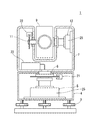
図1は本形態に係る測量機の概略縦断面図である。符号1が測量機であり、測量機1は、整準部3の上に設けられた基盤部4と、基盤部4上を水平回転軸6周りに水平回転する托架部7と、托架部7に鉛直回転軸11周りに鉛直回転する望遠鏡9と、を有する。托架部7には、制御部23が収容されている。測量機1は、手動でターゲットを視準する手動視準モード、決められた測点位置まで自動で回転する自動視準モード、および移動するターゲットを自動で追尾する自動追尾モードの、三種類の動作モードを有する。
FIG. 1 is a schematic vertical sectional view of a surveying instrument according to the present embodiment.
望遠鏡9には、自動視準のための測距光学系、自動追尾のための追尾光学系、および手動視準のための望遠鏡光学系が収容されている。図2は測量機1の光学系の構成を示すブロック図であり、上記光学系の構成の一例である。光源112は、測距光または追尾光として、例えば赤外光を発光するレーザダイオードである。光源112からの発光は、送光レンズ114を透過して反射鏡116に入射し、送光プリズム118に入射した後、平行ガラス120を介してターゲット144に向けて送光され、ターゲット144で反射する。反射光は、平行ガラス120、対物レンズ122を介してダイクロイックプリズム124に入射する。その一部は視準光として合焦レンズ136、正立プリズム138を透過して焦点板140で結像し、接眼レンズ142を介して、作業者の網膜に結像する。反射光の残りは、ビームスプリッタ126に入射し分岐される。分岐された一方の光は第1撮像素子128に入射し、分岐された他方の光は赤外光を除去する波長フィルタ130を透過後、第2撮像素子132に入射する。
The telescope 9 accommodates a ranging optical system for automatic collimation, a tracking optical system for automatic tracking, and a telescope optical system for manual collimation. FIG. 2 is a block diagram showing the configuration of the optical system of the
第1撮像素子128および第2撮像素子132は、イメージセンサ、例えばCCDセンサ、CMOSセンサである。撮像素子128,132で撮られた画像は、画像処理装置134に送られ画像処理される。第1撮像素子128では光源112の赤外光を含む風景画像が撮影され、第2撮像素子132では光源112の赤外光を除いた風景画像が撮影される。画像処理装置134は、点灯画像に相当する第1撮像素子128の画像と消灯画像に相当する第2撮像素子132の画像の差分を求める。差分を取ることにより、ターゲット144の像の中心が求められる。画像処理装置134の結果は制御部23に送られ、制御部23は、ターゲット144の像の中心と望遠鏡の視軸中心からの隔たりが一定値以内に収まる位置をターゲット位置として検出し、自動視準および自動追尾を行う。なお、上記光学系には他の従来公知の構成が採用されてよく、特に上記光学系の各要素は当業者の知識に基づく改変が行われてよい。
The
図1に示すように、水平回転軸6の下端部には水平回転用の超音波モータ5が設けられ、上端部には水平角検出用のエンコーダ21が設けられている。鉛直回転軸11の一方の端部には鉛直回転用の超音波モータ12が設けられ、他方の端部には鉛直角検出用のエンコーダ22が設けられている。エンコーダ21,22は、回転円盤、スリット、発光ダイオード、イメージセンサを有するアブソリュートエンコーダである。この他、インクリメンタルエンコーダが用いられてもよい。
As shown in FIG. 1, a horizontal rotation
図3は図1の超音波モータ5を含む部分の断面斜視図である。超音波モータ5,12の構成について、鉛直回転と水平回転の構成は同等であるので、主に水平回転の構成を用いて説明する。超音波モータ5は、ベース部39から順に、振動を発生する圧電セラミック42、振動を増幅させるステータ43、ステータ43と干渉するロータ46、ロータ46をステータ43側へ押圧するウェーブワッシャ48を、リング状に備える。圧電セラミック42にはSin電極とCos電極が付されており、交互に駆動電圧が掛かることで圧電セラミック42が超音波振動する。圧電セラミック42が振動すると、ステータ43に波状の進行波が形成され、ウェーブワッシャ48の押圧による摩擦によってステータ43とロータ46が相対回転する。図1に示すように、水平側の超音波モータ5は、モータケース25が基盤部4に固定され、ロータ46はモータケース25に固定されているので、ステータ43が回転し、ベース部39を介して水平回転軸6がステータ43と一体に回転する。鉛直側の超音波モータ12は、ステータ43がモータケース25に固定され、ロータ46が回転し、鉛直回転軸11がロータ46と一体に回転する。
FIG. 3 is a sectional perspective view of a portion including the
図4は測量機1の制御ブロック図である。鉛直回転と水平回転のブロック図は同等であるので、水平回転に関して示し、鉛直回転に関しては説明を省略する。測量機1は、制御部23と、エンコーダ21と、測距部61と、追尾部62と、クロック信号発振部63と、駆動回路73と、超音波モータ5を有する。
FIG. 4 is a control block diagram of the surveying
制御部23は、CPU,ROM,RAM等を集積回路に実装したマイクロコントローラによって構成されている。制御部23は、図示を略する外部パーソナルコンピュータからソフトウェアを変更可能である。制御部23は、エンコーダ21の角度信号から回転軸6の回転速度を逐次求める。また、超音波モータ5に対し駆動回路73を介して駆動信号を出力する。そして、回転軸6の回転速度に応じて、駆動信号の波形を変更する。この駆動信号の波形については後に詳述する。
The
測距部61は、制御部23に制御されて、上記測距光学系を用いて測距光をターゲットに照射しその反射光からターゲットを捕捉して自動視準を行う。また、手動または自動視準が完了すると測距を行う。追尾部62は、制御部23に制御されて、上記追尾光学系を用いて追尾光をターゲットに照射してその反射光からターゲットを捕捉して、ターゲットが移動した場合は自動で追尾を行う。
Under the control of the
駆動回路73は、FPGA(Field Programmable Gate Array)731とアナログ回路732によって構成されている。FPGA731は制御部23もしくは図示を略する外部機器によって内部論理回路を定義変更可能である。FPGA731は、可変の駆動周波数(駆動信号の周波数)及び可変の振幅で制御信号を発生させることができ、上記駆動周波数及び上記振幅を動的に変化させることができる。アナログ回路732は、トランス等で構成されており、上記制御信号を増幅させる。駆動回路73は、制御部23からの指令を受けて、FPGA731から上記制御信号を出力し、アナログ回路732で増幅して二種類の位相の異なる駆動信号を生成し、超音波モータ5の圧電セラミック42に付されているSin電極とCos電極に対して出力する。なお、駆動回路73は、ASIC(Application Specific Integrated Circuit)などの他のPLD(Programmable Logic Device)が用いられてもよい。
The
クロック信号発振部63は、クロック信号を制御部23及びFPGA731に出力する。制御部23は、クロック信号に基づき、エンコーダ21の発光周期を制御する。FPGA731は、クロック信号に基づき、駆動信号の振幅,駆動周波数,制御周期の制御と、低速回転域では制御周期内の加速期間(駆動信号を印加する時間)と減速期間(駆動信号を停止する時間)の比率を制御する。なお、本明細書にて、低速回転域とは超音波モータが連続駆動で回転しなくなる速度域のことを意味する。この低速回転域は、超音波モータの製造状態により個々に異なるため、採用する超音波モータの特性を調べることで予め制御部23に定義しておく。
The
図5は本形態に係る超音波モータ5の制御イメージ図である。なお、以降も鉛直回転に関する記載を省略するが、水平回転と同様の制御が行われる。
FIG. 5 is a control image diagram of the
図5の横軸は回転軸6の回転速度Vである。回転速度零からしばらくは、ステータ43とロータ46間の静止摩擦に打ち勝つのに十分な動力が必要である。そのため、回転速度零(V0)からある第1回転速度(V1)までは、駆動信号の波形は矩形波としたほうが、動き出しがスムーズである。従って、この区間は助走区間と位置づけて、助走区間の駆動信号は矩形波とする(第1駆動信号S1)。
The horizontal axis in FIG. 5 is the rotation speed V of the
次に、第1回転速度V1以上となると、動き出しに成功したので、動き出しを維持しつつ、今度は音の問題に対処する必要がある。超音波モータ5は、駆動信号の立ち上がりと立ち下がりの時に異音が生じる。そのため、第1回転速度V1から第2回転速度V2までは、上記矩形波の立ち上がりか立ち下がりのどちらかに勾配を付けることで、動き出しの維持と音の問題の両方に対処する。この区間は微動区間と位置づけて、微動区間の駆動信号は片勾配の矩形波または三角波とする(第2駆動信号S2)。
Next, when the rotation speed becomes equal to or higher than the first rotation speed V1, the movement has been successfully started. Therefore, it is necessary to deal with the sound problem while maintaining the movement. The
次に、第2回転速度V2以上となると、既に動き出しているので、音の問題を重視するのが好ましい。そのため、第2回転速度V2から第3回転速度V3までは、上記矩形波の立ち上がりと立ち下がりの両方に勾配を付けて、音鳴りを低減させる。この区間は間欠区間と位置づけ、間欠区間の駆動信号は両勾配の矩形波又は三角波とする(第3駆動信号S3)。 Next, when the rotation speed becomes equal to or higher than the second rotation speed V2, the movement has already started, so it is preferable to emphasize the sound problem. Therefore, from the second rotation speed V2 to the third rotation speed V3, both the rise and the fall of the rectangular wave are provided with gradients to reduce the noise. This section is regarded as an intermittent section, and the drive signal of the intermittent section is a rectangular wave or a triangular wave having both gradients (third drive signal S3).
最後に、第3回転速度V3以上となると、超音波モータ5は低速回転域を抜け出す。そのため、第3回転速度V3以上では、間欠駆動を止め、駆動信号を連続で印加する。この区間は連続区間と呼び、連続区間の駆動信号は一定とする(第4駆動信号S4)。
Finally, when the rotation speed becomes equal to or higher than the third rotation speed V3, the
上記の第1回転速度V1、第2回転速度V2、および第3回転速度V3の値は、採用する超音波モータの個体特性に応じて予め制御部23に設定しておく。なお、本明細書において「第1回転速度V1から第2回転速度V2まで」と言うときは、「第1回転速度V1以上第2回転速度V2未満」を意味するものとする。
The values of the first rotation speed V1, the second rotation speed V2, and the third rotation speed V3 are set in the
図6は、上記の各区間における超音波モータ5の駆動信号の波形図であり、(a)は第1駆動信号S1の波形図、(b)は第2駆動信号S2の波形図、(c)は第3駆動信号S3の波形図、(d)は第4駆動信号S4の波形図である。いずれも、横軸が時間(t)、縦軸は駆動信号の振幅である。図6における、符号WTが制御周期、符号RTが信号の立ち上がり勾配(上り勾配)を付ける時間、符号FTが信号の立ち下がり勾配(下り勾配)を付ける時間、符号OTが低速回転域において駆動信号を印加する加速時間(加速期間)を示す。なお、上り勾配RT及び下り勾配FTは、図示のような一次関数的な直線に限らず、曲線的な勾配であってもよい。
FIGS. 6A and 6B are waveform diagrams of the drive signal of the
このように、回転軸6の回転速度Vに応じて、駆動信号の波形を、第1駆動信号S1、第2駆動信号S2、第3駆動信号S3、または第4駆動信号S4に変更することで、回転速度Vに応じて生じる要求を満たす制御を行うことができる。
As described above, the waveform of the drive signal is changed to the first drive signal S1, the second drive signal S2, the third drive signal S3, or the fourth drive signal S4 according to the rotation speed V of the
特に、本形態では、低速回転域(第3回転速度V3未満)を、助走区間、微動区間、間欠区間の三段階に分けたことで、超音波モータ5の回転のスムーズさと異音の低減の問題に対し、回転速度に応じた適切な対処を行うことができる。
In particular, in the present embodiment, the low-speed rotation range (less than the third rotation speed V3) is divided into three stages of the approaching section, the fine movement section, and the intermittent section, so that the smooth rotation of the
次に、図7は超音波モータ5の動作モード毎の値の設定例である。制御部23には、手動視準モード、自動視準モード、自動追尾モードの動作モード毎に、制御周期WT、上り勾配RT、下り勾配FT、加速期間OTの値を予め設定しておく。制御部23は、これら制御周期WT、上り勾配RT、下り勾配FT、加速期間OTと駆動信号の振幅を一定とした上で、視準または追尾中の速度調整は駆動周波数fの増減によって行う。なお、駆動周波数fについても、動作モード毎に好適な値または好適な変化域(最小値、最大値)を設定するのも好ましい。
Next, FIG. 7 is an example of setting values for each operation mode of the
図7に例示したように、例えば、自動視準モードは高速制御するのに対し、自動追尾モードでは低速制御するため、追尾モードの制御周期WT(a[ms])は自動視準モードの制御周期WT(A[ms])より短く設定するのも好ましい(a<A)。これにより、自動視準モードでは音鳴りを低減でき、自動追尾モードではフィードバック応答を早めて追尾性能を上げることができる。また、手動視準モードは、自動視準モードよりも時間的な制約が多少緩和されるため、自動視準モードの制御周期WT(A[ms])よりも手動視準モードの制御周期WTを長く設定し(2.5A)、その分勾配を長く設定(1.25A)して音を緩和させるようにしてもよい。 As illustrated in FIG. 7, for example, the automatic collimation mode performs high-speed control, whereas the automatic tracking mode performs low-speed control. Therefore, the control cycle WT (a [ms]) of the tracking mode is controlled in the automatic collimation mode. It is also preferable to set the period shorter than the period WT (A [ms]) (a <A). Thus, in the automatic collimation mode, the noise can be reduced, and in the automatic tracking mode, the feedback response can be accelerated to improve the tracking performance. Further, in the manual collimation mode, the time constraint is somewhat relaxed as compared with the automatic collimation mode. A longer setting (2.5 A) and a longer setting of the gradient (1.25 A) may mitigate the sound.
また、手動視準モードは、測点位置まで大きく回転させた後細かく回転させるので、使用する速度域は、第1回転速度V1から第3回転速度V3までである。よって、低速回転用に第2駆動信号S2と高速回転用に第3駆動信号S3の波形を使用すれば好適な制御が行える。このように、動作モードによっては、全ての第1〜第4駆動信号を使用することなく、使用する回転速度と合致する区間の駆動信号のみを設定し、その他の区間の駆動信号については設定を省略してもよい。 Further, in the manual collimation mode, since the rotation is finely performed after the rotation to the measurement point position, the speed range to be used is from the first rotation speed V1 to the third rotation speed V3. Therefore, if the waveform of the second drive signal S2 for low-speed rotation and the waveform of the third drive signal S3 for high-speed rotation are used, suitable control can be performed. As described above, depending on the operation mode, only the drive signal of the section that matches the rotation speed to be used is set without using all of the first to fourth drive signals, and the setting of the drive signal of the other sections is not performed. It may be omitted.
このように、測量機1の備える動作モード毎に、駆動信号の制御周期WT、上り勾配RT、下り勾配FT、加速期間OT、駆動周波数fを設定することで、動作モードに応じて生じる要求を満たす制御を行うことができる。
As described above, by setting the control cycle WT of the drive signal, the up slope RT, the down slope FT, the acceleration period OT, and the drive frequency f for each operation mode of the surveying
次に、本形態の変形例について述べる。例えば、測量機1に、軸ブレを解消する動作モードを追加してもよい。超音波モータ5は、ステータ43とロータ46間の摩擦力により無通電時に高い保持力を有するので、モータ動作が止まると、回転軸6が軸振れした位置から元の位置に戻らないという不具合が生じることがある。これを解消するために、ターゲット位置の回転角まで到達した後に、超音波モータ5に、同等の回転量を与える一組の順方向の駆動信号と逆方向の駆動信号を出力して、回転軸6を軸振れした位置から元の位置に戻す動作モードを、測量機1に設けてもよい。この軸ブレ解消モードに対し、この動作モードに使用する速度域と合致する区間の駆動信号を設定し、その制御周期WT、上り勾配RT、下り勾配FT、加速期間OT、駆動周波数fを設定してもよい。
Next, a modified example of this embodiment will be described. For example, an operation mode for eliminating axis shake may be added to the surveying
以上、本発明の好ましい実施の形態及び変形例を示したが、上記の実施の形態および変形例を当業者の知識に基づいて組み合わせることは可能であり、そのような改変は本発明の範囲に含まれる。 As described above, the preferred embodiments and modified examples of the present invention have been described. However, the above-described embodiments and modified examples can be combined based on the knowledge of those skilled in the art, and such modifications are included in the scope of the present invention. included.
1 測量機
5,12 超音波モータ
6,11 回転軸
21,22 エンコーダ
23 制御部
S1 第1駆動信号
S2 第2駆動信号
S3 第3駆動信号
S4 第4駆動信号
WT 制御周期
RT,FT 勾配
OT 加速期間
f 駆動周波数
Claims (4)
前記回転軸の回転速度が零から第1回転速度までは、前記駆動信号を制御周期内で印加及び停止する矩形波を作る第1駆動信号で制御し、
前記第1回転速度から第2回転速度までは、前記矩形波の立ち上がり又は立下りに勾配が付いた第2駆動信号で制御し、
前記第2回転速度から第3回転速度までは、前記矩形波の立ち上がり及び立下りに勾配が付いた第3駆動信号で制御し、
前記第3回転速度からは、前記駆動信号を連続的に印加する第4駆動信号で制御し、
前記測量機が有する複数の動作モードに対し、前記動作モード毎に、前記第1〜第4駆動信号の前記制御周期及び前記周波数と、前記第1〜第3駆動信号の前記駆動信号を印加する時間である加速期間と、前記第2〜第3駆動信号の前記勾配の値を設定することを特徴とする超音波モータの制御方法。
A method for controlling an ultrasonic motor that drives a rotation axis of a surveying instrument by receiving a frequency-variable drive signal,
When the rotation speed of the rotation shaft is from zero to the first rotation speed, the drive signal is controlled by a first drive signal that generates a rectangular wave that is applied and stopped within a control cycle,
From the first rotation speed to the second rotation speed, the rising and falling of the rectangular wave is controlled by a second drive signal having a slope,
From the second rotation speed to the third rotation speed, the rise and fall of the rectangular wave are controlled by a third drive signal having a slope,
From the third rotation speed, control is performed by a fourth drive signal that continuously applies the drive signal ,
The control cycle and the frequency of the first to fourth drive signals and the drive signals of the first to third drive signals are applied to the plurality of operation modes of the surveying instrument for each of the operation modes. A method for controlling an ultrasonic motor, comprising setting an acceleration period as time and a value of the gradient of the second to third drive signals .
The method according to claim 1, wherein in at least one of the operation modes, at least one of the controls based on the first to fourth drive signals is omitted .
周波数可変の駆動信号を受けて前記回転軸を駆動する超音波モータと、 An ultrasonic motor that drives the rotating shaft in response to a variable frequency drive signal,
前記回転軸の回転速度を検出するエンコーダと、 An encoder for detecting a rotation speed of the rotation shaft;
前記回転速度が零から第1回転速度までは、前記駆動信号を制御周期内で印加及び停止する矩形波を作る第1駆動信号で制御し、前記第1回転速度から第2回転速度までは、前記矩形波の立ち上がり又は立下りに勾配が付いた第2駆動信号で制御し、前記第2回転速度から第3回転速度までは、前記矩形波の立ち上がり及び立下りに勾配が付いた第3駆動信号で制御し、前記第3回転速度からは、前記駆動信号を連続的に印加する第4駆動信号で制御し、前記測量機が有する複数の動作モードに対し、前記動作モード毎に、前記第1〜第4駆動信号の前記制御周期及び前記周波数と、前記第1〜第3駆動信号の前記駆動信号を印加する時間である加速期間と、前記第2〜第3駆動信号の前記勾配の値を設定する制御部と、 From the rotation speed of zero to the first rotation speed, the drive signal is controlled by a first drive signal for generating a rectangular wave for applying and stopping within a control cycle, and from the first rotation speed to the second rotation speed, Control is performed by a second drive signal having a slope at the rise or fall of the rectangular wave. From the second rotation speed to the third rotation speed, a third drive having a slope at the rise and fall of the square wave. Control by a signal, and from the third rotation speed, control by a fourth drive signal that continuously applies the drive signal, and for a plurality of operation modes of the surveying instrument, The control period and the frequency of the first to fourth drive signals, an acceleration period which is a time for applying the drive signal of the first to third drive signals, and the value of the gradient of the second to third drive signals A control unit for setting
を有することを特徴とする測量機。 A surveying instrument comprising:
Priority Applications (3)
| Application Number | Priority Date | Filing Date | Title |
|---|---|---|---|
| JP2016085770A JP6672055B2 (en) | 2016-04-22 | 2016-04-22 | Ultrasonic motor control method and surveying instrument therefor |
| US15/490,457 US9979324B2 (en) | 2016-04-22 | 2017-04-18 | Method for controlling ultrasonic motor and surveying instrument for the same |
| EP17167494.8A EP3236578B1 (en) | 2016-04-22 | 2017-04-21 | Control of ultrasonic motor in surveying instrument |
Applications Claiming Priority (1)
| Application Number | Priority Date | Filing Date | Title |
|---|---|---|---|
| JP2016085770A JP6672055B2 (en) | 2016-04-22 | 2016-04-22 | Ultrasonic motor control method and surveying instrument therefor |
Publications (3)
| Publication Number | Publication Date |
|---|---|
| JP2017194397A JP2017194397A (en) | 2017-10-26 |
| JP2017194397A5 JP2017194397A5 (en) | 2019-03-07 |
| JP6672055B2 true JP6672055B2 (en) | 2020-03-25 |
Family
ID=58638686
Family Applications (1)
| Application Number | Title | Priority Date | Filing Date |
|---|---|---|---|
| JP2016085770A Active JP6672055B2 (en) | 2016-04-22 | 2016-04-22 | Ultrasonic motor control method and surveying instrument therefor |
Country Status (3)
| Country | Link |
|---|---|
| US (1) | US9979324B2 (en) |
| EP (1) | EP3236578B1 (en) |
| JP (1) | JP6672055B2 (en) |
Families Citing this family (5)
| Publication number | Priority date | Publication date | Assignee | Title |
|---|---|---|---|---|
| JP6691419B2 (en) * | 2016-04-15 | 2020-04-28 | 株式会社トプコン | Control method of ultrasonic motor and surveying instrument therefor |
| USD834970S1 (en) * | 2017-03-03 | 2018-12-04 | Topcon Corporation | Surveying instrument |
| USD835532S1 (en) * | 2017-03-03 | 2018-12-11 | Topcon Corporation | Surveying instrument |
| US11064097B2 (en) * | 2018-11-01 | 2021-07-13 | Canon Kabushiki Kaisha | Imaging apparatus for adjusting pressing forces of an ultrasonic motor and a waterproof member |
| EP4222450B1 (en) * | 2020-09-30 | 2024-06-26 | Trimble AB | Method for operating a geodetic instrument, and related geodetic instrument |
Family Cites Families (14)
| Publication number | Priority date | Publication date | Assignee | Title |
|---|---|---|---|---|
| JPS627379A (en) * | 1985-06-28 | 1987-01-14 | Matsushita Electric Ind Co Ltd | Ultrasonic wave motor apparatus |
| US4794294A (en) * | 1986-06-12 | 1988-12-27 | Canon Kabushiki Kaisha | Vibration wave motor |
| JPH03145976A (en) * | 1989-10-30 | 1991-06-21 | Nikon Corp | Drive unit for ultrasonic motor |
| JPH0479779A (en) * | 1990-07-18 | 1992-03-13 | Asmo Co Ltd | Driving circuit for ultrasonic motor |
| EP0537384A1 (en) * | 1991-08-22 | 1993-04-21 | Mitsubishi Jukogyo Kabushiki Kaisha | Rotation control system for ultrasonic motor |
| JP2986654B2 (en) * | 1993-07-13 | 1999-12-06 | シャープ株式会社 | Piezoelectric vibration control device |
| JP4688245B2 (en) * | 1998-06-02 | 2011-05-25 | セイコーインスツル株式会社 | Electronic system with positioning system and ultrasonic motor |
| JP4253866B2 (en) * | 1998-06-08 | 2009-04-15 | 株式会社ニコン | Vibration actuator driving apparatus and vibration actuator driving method |
| JP4803892B2 (en) * | 2001-03-29 | 2011-10-26 | 株式会社ニコン・トリンブル | Surveying instrument |
| JP4894308B2 (en) * | 2006-03-13 | 2012-03-14 | コニカミノルタオプト株式会社 | Drive device |
| EP2237338A1 (en) * | 2009-04-03 | 2010-10-06 | Leica Geosystems AG | Piezo drive |
| JP6105298B2 (en) | 2013-01-17 | 2017-03-29 | 株式会社トプコン | Surveying instrument rotation drive and surveying instrument |
| JP6302346B2 (en) * | 2013-05-14 | 2018-03-28 | キヤノン株式会社 | Drive control apparatus and drive control method for ultrasonic motor |
| DE202014008041U1 (en) * | 2014-10-10 | 2014-11-03 | Leica Geosystems Ag | Surveyor with traveling wave drive |
-
2016
- 2016-04-22 JP JP2016085770A patent/JP6672055B2/en active Active
-
2017
- 2017-04-18 US US15/490,457 patent/US9979324B2/en active Active
- 2017-04-21 EP EP17167494.8A patent/EP3236578B1/en active Active
Also Published As
| Publication number | Publication date |
|---|---|
| US9979324B2 (en) | 2018-05-22 |
| EP3236578A1 (en) | 2017-10-25 |
| US20170310248A1 (en) | 2017-10-26 |
| EP3236578B1 (en) | 2019-03-20 |
| JP2017194397A (en) | 2017-10-26 |
Similar Documents
| Publication | Publication Date | Title |
|---|---|---|
| JP6672055B2 (en) | Ultrasonic motor control method and surveying instrument therefor | |
| US8203608B2 (en) | Dynamic image recording system with superimposition movement during scanning movement for momentary image stopping and method | |
| JP5740321B2 (en) | Distance measuring device, distance measuring method and control program | |
| JP5653715B2 (en) | Laser surveyor | |
| US20170045734A1 (en) | Method for calculating scanning pattern of light, and optical scanning apparatus | |
| US10211387B2 (en) | Method for controlling ultrasonic motor and surveying instrument for the same | |
| JPS6043752B2 (en) | Motor drive device | |
| KR101278862B1 (en) | Oscillator device, optical deflecting device and method of controlling the same | |
| US20190187459A1 (en) | Optical scanner | |
| JP6691419B2 (en) | Control method of ultrasonic motor and surveying instrument therefor | |
| WO2018134932A1 (en) | Amplitude measuring device and vibration measuring method in amplitude measuring device | |
| JP5998723B2 (en) | Drive device | |
| CN114355620A (en) | Laser speckle suppression device and method for 3D vision | |
| JP7001455B2 (en) | Optical scanning device | |
| JP6669538B2 (en) | Control method of ultrasonic motor provided in surveying instrument and surveying instrument therefor | |
| JP6990573B2 (en) | Optical scanning device | |
| JP4126030B2 (en) | Optical disc master exposure system | |
| JP6615653B2 (en) | Surveying instrument | |
| JP2007057695A5 (en) | ||
| JP2017090793A (en) | Projector | |
| JPS59139015A (en) | Galvanomirror scanning system | |
| KR101545491B1 (en) | Scanning synchronization method in interferometry | |
| JPH0293806A (en) | Moving speed controller for travelling object | |
| JP2017175754A5 (en) | ||
| JP2017125736A (en) | Excitation system |
Legal Events
| Date | Code | Title | Description |
|---|---|---|---|
| A521 | Request for written amendment filed |
Free format text: JAPANESE INTERMEDIATE CODE: A523 Effective date: 20190121 |
|
| A621 | Written request for application examination |
Free format text: JAPANESE INTERMEDIATE CODE: A621 Effective date: 20190121 |
|
| A977 | Report on retrieval |
Free format text: JAPANESE INTERMEDIATE CODE: A971007 Effective date: 20191125 |
|
| A131 | Notification of reasons for refusal |
Free format text: JAPANESE INTERMEDIATE CODE: A131 Effective date: 20191128 |
|
| A521 | Request for written amendment filed |
Free format text: JAPANESE INTERMEDIATE CODE: A523 Effective date: 20200108 |
|
| TRDD | Decision of grant or rejection written | ||
| A01 | Written decision to grant a patent or to grant a registration (utility model) |
Free format text: JAPANESE INTERMEDIATE CODE: A01 Effective date: 20200226 |
|
| A61 | First payment of annual fees (during grant procedure) |
Free format text: JAPANESE INTERMEDIATE CODE: A61 Effective date: 20200304 |
|
| R150 | Certificate of patent or registration of utility model |
Ref document number: 6672055 Country of ref document: JP Free format text: JAPANESE INTERMEDIATE CODE: R150 |
|
| R250 | Receipt of annual fees |
Free format text: JAPANESE INTERMEDIATE CODE: R250 |
|
| R250 | Receipt of annual fees |
Free format text: JAPANESE INTERMEDIATE CODE: R250 |