EP3236536B1 - Zipper-type electrical connector - Google Patents
Zipper-type electrical connector Download PDFInfo
- Publication number
- EP3236536B1 EP3236536B1 EP16863208.1A EP16863208A EP3236536B1 EP 3236536 B1 EP3236536 B1 EP 3236536B1 EP 16863208 A EP16863208 A EP 16863208A EP 3236536 B1 EP3236536 B1 EP 3236536B1
- Authority
- EP
- European Patent Office
- Prior art keywords
- chain
- engaging
- electrical
- electrical connection
- engaging elements
- Prior art date
- Legal status (The legal status is an assumption and is not a legal conclusion. Google has not performed a legal analysis and makes no representation as to the accuracy of the status listed.)
- Active
Links
Images

Classifications
-
- H—ELECTRICITY
- H01—ELECTRIC ELEMENTS
- H01R—ELECTRICALLY-CONDUCTIVE CONNECTIONS; STRUCTURAL ASSOCIATIONS OF A PLURALITY OF MUTUALLY-INSULATED ELECTRICAL CONNECTING ELEMENTS; COUPLING DEVICES; CURRENT COLLECTORS
- H01R13/00—Details of coupling devices of the kinds covered by groups H01R12/70 or H01R24/00 - H01R33/00
- H01R13/02—Contact members
- H01R13/28—Contacts for sliding cooperation with identically-shaped contact, e.g. for hermaphroditic coupling devices
-
- H—ELECTRICITY
- H01—ELECTRIC ELEMENTS
- H01R—ELECTRICALLY-CONDUCTIVE CONNECTIONS; STRUCTURAL ASSOCIATIONS OF A PLURALITY OF MUTUALLY-INSULATED ELECTRICAL CONNECTING ELEMENTS; COUPLING DEVICES; CURRENT COLLECTORS
- H01R13/00—Details of coupling devices of the kinds covered by groups H01R12/70 or H01R24/00 - H01R33/00
- H01R13/62—Means for facilitating engagement or disengagement of coupling parts or for holding them in engagement
- H01R13/629—Additional means for facilitating engagement or disengagement of coupling parts, e.g. aligning or guiding means, levers, gas pressure electrical locking indicators, manufacturing tolerances
-
- H—ELECTRICITY
- H01—ELECTRIC ELEMENTS
- H01R—ELECTRICALLY-CONDUCTIVE CONNECTIONS; STRUCTURAL ASSOCIATIONS OF A PLURALITY OF MUTUALLY-INSULATED ELECTRICAL CONNECTING ELEMENTS; COUPLING DEVICES; CURRENT COLLECTORS
- H01R13/00—Details of coupling devices of the kinds covered by groups H01R12/70 or H01R24/00 - H01R33/00
- H01R13/02—Contact members
- H01R13/20—Pins, blades, or sockets shaped, or provided with separate member, to retain co-operating parts together
-
- H—ELECTRICITY
- H05—ELECTRIC TECHNIQUES NOT OTHERWISE PROVIDED FOR
- H05K—PRINTED CIRCUITS; CASINGS OR CONSTRUCTIONAL DETAILS OF ELECTRIC APPARATUS; MANUFACTURE OF ASSEMBLAGES OF ELECTRICAL COMPONENTS
- H05K1/00—Printed circuits
- H05K1/02—Details
- H05K1/11—Printed elements for providing electric connections to or between printed circuits
- H05K1/118—Printed elements for providing electric connections to or between printed circuits specially for flexible printed circuits, e.g. using folded portions
-
- H—ELECTRICITY
- H05—ELECTRIC TECHNIQUES NOT OTHERWISE PROVIDED FOR
- H05K—PRINTED CIRCUITS; CASINGS OR CONSTRUCTIONAL DETAILS OF ELECTRIC APPARATUS; MANUFACTURE OF ASSEMBLAGES OF ELECTRICAL COMPONENTS
- H05K3/00—Apparatus or processes for manufacturing printed circuits
- H05K3/36—Assembling printed circuits with other printed circuits
- H05K3/361—Assembling flexible printed circuits with other printed circuits
- H05K3/365—Assembling flexible printed circuits with other printed circuits by abutting, i.e. without alloying process
-
- H—ELECTRICITY
- H01—ELECTRIC ELEMENTS
- H01R—ELECTRICALLY-CONDUCTIVE CONNECTIONS; STRUCTURAL ASSOCIATIONS OF A PLURALITY OF MUTUALLY-INSULATED ELECTRICAL CONNECTING ELEMENTS; COUPLING DEVICES; CURRENT COLLECTORS
- H01R12/00—Structural associations of a plurality of mutually-insulated electrical connecting elements, specially adapted for printed circuits, e.g. printed circuit boards [PCB], flat or ribbon cables, or like generally planar structures, e.g. terminal strips, terminal blocks; Coupling devices specially adapted for printed circuits, flat or ribbon cables, or like generally planar structures; Terminals specially adapted for contact with, or insertion into, printed circuits, flat or ribbon cables, or like generally planar structures
- H01R12/70—Coupling devices
- H01R12/77—Coupling devices for flexible printed circuits, flat or ribbon cables or like structures
- H01R12/777—Coupling parts carrying pins, blades or analogous contacts
-
- H—ELECTRICITY
- H05—ELECTRIC TECHNIQUES NOT OTHERWISE PROVIDED FOR
- H05K—PRINTED CIRCUITS; CASINGS OR CONSTRUCTIONAL DETAILS OF ELECTRIC APPARATUS; MANUFACTURE OF ASSEMBLAGES OF ELECTRICAL COMPONENTS
- H05K2201/00—Indexing scheme relating to printed circuits covered by H05K1/00
- H05K2201/09—Shape and layout
- H05K2201/09145—Edge details
- H05K2201/09181—Notches in edge pads
-
- H—ELECTRICITY
- H05—ELECTRIC TECHNIQUES NOT OTHERWISE PROVIDED FOR
- H05K—PRINTED CIRCUITS; CASINGS OR CONSTRUCTIONAL DETAILS OF ELECTRIC APPARATUS; MANUFACTURE OF ASSEMBLAGES OF ELECTRICAL COMPONENTS
- H05K2201/00—Indexing scheme relating to printed circuits covered by H05K1/00
- H05K2201/09—Shape and layout
- H05K2201/09209—Shape and layout details of conductors
- H05K2201/09654—Shape and layout details of conductors covering at least two types of conductors provided for in H05K2201/09218 - H05K2201/095
- H05K2201/09709—Staggered pads, lands or terminals; Parallel conductors in different planes
-
- H—ELECTRICITY
- H05—ELECTRIC TECHNIQUES NOT OTHERWISE PROVIDED FOR
- H05K—PRINTED CIRCUITS; CASINGS OR CONSTRUCTIONAL DETAILS OF ELECTRIC APPARATUS; MANUFACTURE OF ASSEMBLAGES OF ELECTRICAL COMPONENTS
- H05K2201/00—Indexing scheme relating to printed circuits covered by H05K1/00
- H05K2201/20—Details of printed circuits not provided for in H05K2201/01 - H05K2201/10
- H05K2201/2072—Anchoring, i.e. one structure gripping into another
Definitions
- the present invention relates to relates to electrical connectors in electronics industry, and more particularly to a zipper type electrical connector.
- an electronic cable connector such as cable connectors, flexible cable connectors, FPC connectors, etc.
- the electronic cable connection is generally implemented by using a terminal plug, welding, etc., in particular, a FPC cable connection is very cumbersome.
- Zipper type electrical connectors have been disclosed in the related art, for example in CA 995 320 A , US 4 931 021 , GB 2 378 054 , US 5 499 927 , US 2010/136804 and WO 2006/053319 A2 .
- these zipper type electrical connectors have many disadvantages, such as a complicated manufacturing process, uncapable of wiring densely or an unstable connection, which cannot meet the increasing demands of the electronics industry.
- the present disclosure provides a zipper type electrical connector according to claim 6.
- each of engaging elements comprises at least an electrical connection portion and an electrical insulation portion.
- the electrical connection portion and the electrical insulation portion are in a form of a layer.
- the electrical connection portion comprises a metal material
- the electrical insulation portion comprises an insulating material
- the metal material comprises metallic copper
- the insulating material comprises plastic
- the slider is electrically insulated.
- the zipper type electrical connector is a cable connector, a soft cable connector, or a flexible circuit board connector.
- the present disclosure also provides a chain, according to claim 1, for a zipper type electrical connector.
- the chain further comprises a slider slidably disposed on the chain, and the slider is configured such that, the engaging elements of the chain and those of the other chain are switched between the engaged state and the disengaged state by sliding the slider.
- each of the plurality of engaging elements comprises at least an electrical connection portion and an electrical insulation portion.
- each of the engaging elements comprises one electrical connection portion and one electrical insulation portion, the electrical connection portion and the electrical insulation portion of each engaging element on the chain being arranged alternately, an engaging tooth and an engaging groove being formed on each of the electrical connection portion and the electrical insulation portion, and wherein, in the engaging state, the engaging tooth of each engaging element of the chain is engaged into the engaging groove of each engaging element of the other chain.
- the electrical connection portion comprises a metal material
- the electrical insulation portion comprises an insulating material
- the metal material comprises metallic copper
- the insulating material comprises plastic
- the slider is electrically insulated.
- the present disclosure further provides an electrical device comprising the chain according to any one of the above embodiments.
- a zipper type electrical connector comprising: a first chain and a second chain; a plurality of engaging elements provided on the first and second chains respectively; and a slider slidably connected to the first and second chains, such that the engaging elements on the first and second chains are switched between an engaged state and a disengaged state; wherein, in the engaged state, the engaging elements on the first chain and those on the second chain are arranged close to and staggered with respect to each other, and at least one of the engaging elements on one of the first and second chains and at least one of the engaging elements on the other of the first and second chains are connected to each other one by one to achieve an electrical connection; in the disengaged state, the engaging elements on the first chain is disengaged from those on the second chain, and the engaging elements on the first and second chains are electrically insulated from each other.
- the present invention achieves at least the following technical effects:
- the present disclosure provides a zipper type electrical connector which adopts the zipper to realize a design concept of the electrical connection between the corresponding engaging elements of two chains. It facilitates connection between electronic cables (such as cables, flexible cables, FPC cables, etc.) in a way of a simple, convenient, secured and reliable zipper type connection, thus providing a more convenient and efficient electrical connection manner.
- the zipper type electrical connector provided by the present disclosure not only facilitates the replacement of a test object during the test, but also facilitates saving material during maintenance.
- a zipper type electrical connector 10 comprising: a first chain 11 and a second chain 12; a plurality of engaging elements 13 provided on the first and second chains 11, 12 respectively; and a slider 14 slidably connected to the first and second chains 11, 12.
- the engaging elements 13 on the first chain 11 and the engaging elements 13 on the second chain 12 are arranged close to and staggered with respect to each other, and each of the engaging elements 13 includes at least an electrical connection portion and an electrical insulation portion.
- the slider 14 is slidably connected to the first and second chains 11, 12, such that the engaging elements 13 on the first and second chains 11, 12 are switched between an engaged state and a disengaged state.
- the electrical connection portion of the engaging element 13 of one of the first and second chains 11, 12 are connected to the electrical connection portion of the corresponding engaging element 13 of the other of the first and second chains 11, 12 to achieve an electrical connection, and the electrical insulation portion of each of engaging elements 13 electrically isolates two adjacent engaging elements on one same chain.
- the zipper type electrical connector realizes a mechanical connection between the corresponding engaging elements on the two chains (e.g., the first chain 11 and the second chain 12) by way of a zipper, so that the electrical connection portions of the corresponding engaging elements on the different chains are connected to each other one by one to achieve an electrical connection, while the adjacent engaging elements on the same chain (e.g., the first chain 11 or the second chain 12) are electrically insulated to each other by the electrical insulation portion. Therefore, as shown in Fig.
- the aforementioned zipper type electrical connector 10 can be applied to the mechanical and electrical connection between the first flexible circuit board 200 and the second flexible circuit board 300, wherein, through the zipper type electrical connector 10, the electric wires 200A in the first flexible circuit board 200 are electrically connected with the corresponding electrical wires 300A in the second flexible circuit board 300, respectively, to achieve an electrical connection between the first and second flexible circuit boards 200, 300.
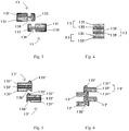
- the engaging elements 13 may be of different construction designs.
- FIGs. 3 and 4 are schematic views of an enlarged structure of a first embodiment of an engaging element of a zipper type electrical connector shown in Fig. 2 , respectively, wherein Fig. 3 shows a state in which a pair of engaging elements are disengaged from each other and Fig. 4 shows a state in which several engaging elements are engaged.
- each of the engaging elements 13 comprises one electrical connection portion 131 and one electrical insulation portion 132.
- the electrical connection portion 131 and the electrical insulation portion 132 of each engaging element on one same chain are arranged alternately.
- each engaging element 13 includes an electrical connection portion 131 facing an adjacent engaging element 13 of the same chain and an electrical insulation portion 132 facing another adjacent engaging element 13 on the same chain.
- an engaging tooth 133 and an engaging groove 134 are formed on each of the electrical connection portion 131 and the electrical insulation portion 132.
- the engaging tooth 133 of the electrical connection portion 131 of each engaging element 13 of one chain is engaged into the engaging groove 134 of the electrical connection portion 131 of each engaging element 13 of the other chain, so as to achieve an electrical connection between the corresponding engaging elements 13 on two chains.
- the engaging tooth 133 of the electrical insulation portion 132 of each engaging element 13 of one chain is engaged into the engaging groove 134 of the electrical insulation portion 132 of each engaging element 13 of the other chain so as to achieve an electrical insulation between two engaging elements on the same chain.
- the corresponding engaging elements 13 in two chains are separated from each other without any connection and contact therebetween, thereby achieving an electrical insulation.
- Figs. 5 and 6 are schematic views of an enlarged structure of the engaging elements in the zipper type electrical connector shown in Fig. 2 , respectively, wherein Fig. 5 shows a state in which a pair of engaging elements are disengaged from each other and Fig. 6 shows a state in which several engaging elements are engaged. This does not form part of the invention but represents background art that is useful for understanding the invention.
- each of engaging elements 13' comprises a first electrical connection portion 131', a second electrical connection portion 131', and an electrical insulation portion 132' arranged between the first and second electrical connection portions and electrically insulating therebetween.
- the first electrical connection portion, the electrical insulation portion, and the second electrical connection portion of each engaging element of the same chain are sequentially arranged in an order of the first electrical connection portion, the electrical insulation portion and the second electrical connection portion.
- each engaging element 13' includes a first electrical connection portion 131' facing an adjacent engaging element 13' of the same chain, a second electrical connection portion 131' facing another adjacent engaging element of the same chain, and an electrical insulation portion 132' arranged between the first and second electrical connection portions and electrically insulating therebetween. Further, an engaging tooth 135' is formed on the first electrical connection portion 131', and an engaging groove 136' is formed on the second electrical connection portion 131'.
- the engaging tooth 135' of each engaging element 13' of one of the first and second chains is engaged into the engaging groove 136' of the corresponding engaging element 13' of the other of the first and second chains so as to achieve a electrical connection between the corresponding engaging elements 13' of two chains.
- the electrical insulation portion 132' which electrically insulates the first and second electrical connection portion 131' from each other is arranged between the first and second electrical connection portions, an electrical insulation is ensured between two adjacent engaging elements of the same chain. In a state in which two chains are separated from each other, the corresponding engaging elements 13' of the two chains are disengaged from each other, without any connection or touch therebetween, so as to achieve an electrical insulation.
- the electrical connection portion 131, 131' and the electrical insulation portion 132, 132' are optionally in a form of a layer.
- the electrical connection portion and the electrical insulation portion may be made of layers with different thicknesses or with an identical thickness.
- density of the engaging elements may be adjusted by changing the number of the engaging elements in the chain and thickness of each individual engaging element.
- the electrical connection portions 131, 131' are made of metal material to achieve an electrical connection, while the electrical insulation portions 132, 132' are made of an insulating material so as to achieve an electrical insulation.
- the metal material optionally comprises metallic copper
- the insulating material optionally comprises plastic.
- the slider 14 is slidably connected to the first and second chains 11, 12, such that the engaging elements 13 on the first and second chains 11, 12 are switched between an engaged state and a disengaged state. Therefore, the slider 14 may be electrically insulated, and may be made of plastic for example. Further, the size of the slider 14 is adapted to that of the chain and engaging elements. Further, according to actual situation, the size of the slider 14 may be set as small as possible. Further, to ensure stability of the connection, the slider 14 should be configured to be secured at an end of the chain.
- the chain on which the engaging elements are provided should be made of an insulating material, for example, insulating cloth or plastic.
- the zipper type electrical connector may also be a cable connector, a flexible cable connector, or any other suitable connector.
- the previously described zipper type electrical connector may be an FPC cable suitable usable between an electrical element CELL and a printed circuit board assembly PCBA so to facilitate testing and maintenance, especially facilitate changing an electrical elements or a printed circuit board assembly in testing.
- material can also be saved in the after-sales maintenance phase.
- a chain comprising a plurality of engaging elements.
- the chain is adapted to be mated with another chain with a plurality of engaging elements, so as to be switched between an engaged state and a disengaged state.
- the plurality of engaging elements of the chain are configured to be arranged close to and stagger with a plurality of corresponding engaging elements of the other chain to achieve an electrical conduction, and to be disengaged from the plurality of engaging elements of the other chain in the disengaged state, without any connection or touch therebetween so as to achieve an electrical insulation.
- each of the plurality of engaging elements comprises an electrical connection portion and an electrical insulation portion.
- the electrical connection portions of an engaging element of one chain are connected, one by one, to the electrical connection portions of a corresponding engaging element of the other chain to achieve an electrical connection, and the electrical insulation portion of each engaging element electrically isolates two adjacent engaging elements on one same chain.
- one of the chain and the other chain further comprises a slider slidably disposed thereon.
- the engaging elements of the chain and those of the other chain are switched between the engaged state and the disengaged state by sliding the slider.
- the chain corresponds to one of the first and second chains 11, 12. Therefore, in these embodiments, the chain may have same features as those in the above mentioned first and second chains 11, 12. To avoid duplication, these technical features are not repeated here.
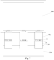
- the present disclosure further provides an electrical device.
- the chain 11 may be arranged on the electrical device 400, such as a display panel.
- the other chain to be mated with it may be arranged on a flexible circuit board so as to achieve an electrical connection between the display panel and the flexible circuit board 401.
- the chain may be arranged in a flexible circuit board (FPC) 401.
- the other chain 12 to be mated therewith may be arranged on another flexible circuit board 501 so as to achieve an electrical connection between two flexible circuit boards, by the cooperation of two chains.
- FPC flexible circuit board
- the zipper type electrical connector provided by the present disclosure adopts the zipper to realize a design concept of the electrical connection between the corresponding engaging elements of two chains. It facilitates connection between electronic cables (such as cables, flexible cables, FPC cables, etc.) in a way of a simple, convenient and reliable zipper type connection, thus providing a more convenient and efficient electrical connection manner.
- the zipper type electrical connector provided by the present disclosure not only facilitates the replacement of the test object during the test, but also facilitates saving material during maintenance.
Landscapes
- Engineering & Computer Science (AREA)
- Microelectronics & Electronic Packaging (AREA)
- Metallurgy (AREA)
- Manufacturing & Machinery (AREA)
- Details Of Connecting Devices For Male And Female Coupling (AREA)
- Coupling Device And Connection With Printed Circuit (AREA)
- Manufacturing Of Electrical Connectors (AREA)
- Insulated Conductors (AREA)
Description
- This application claims the benefit of Chinese Patent Application No.
201620081105.9 filed on January 27, 2016 - The present invention relates to relates to electrical connectors in electronics industry, and more particularly to a zipper type electrical connector.
- In the electronics industry, it is often necessary to use an electronic cable connector (such as cable connectors, flexible cable connectors, FPC connectors, etc.) to achieve a plurality of electrical connections between devices and/or components. At present, the electronic cable connection is generally implemented by using a terminal plug, welding, etc., in particular, a FPC cable connection is very cumbersome. Zipper type electrical connectors have been disclosed in the related art, for example in
CA 995 320 A ,US 4 931 021 ,GB 2 378 054 US 5 499 927 ,US 2010/136804 andWO 2006/053319 A2 . However, these zipper type electrical connectors have many disadvantages, such as a complicated manufacturing process, uncapable of wiring densely or an unstable connection, which cannot meet the increasing demands of the electronics industry. - It is at least one object of the present invention to provide a zipper type electrical connector which can be operated easily and connected stably and reliably.
- It is a further object of the present invention to provide a zipper type electrical connector which facilitates disassembly and/or maintenance.
- Accordingly, the present disclosure provides a zipper type electrical connector according to claim 6.
- In an embodiment, each of engaging elements comprises at least an electrical connection portion and an electrical insulation portion.
- In an embodiment, the electrical connection portion and the electrical insulation portion are in a form of a layer.
- In an embodiment, in each engaging element, the electrical connection portion comprises a metal material, and the electrical insulation portion comprises an insulating material.
- In an embodiment, the metal material comprises metallic copper, and the insulating material comprises plastic.
- In an embodiment, the slider is electrically insulated.
- In an embodiment, the zipper type electrical connector is a cable connector, a soft cable connector, or a flexible circuit board connector.
- The present disclosure also provides a chain, according to claim 1, for a zipper type electrical connector.
- In an embodiment, the chain further comprises a slider slidably disposed on the chain, and the slider is configured such that, the engaging elements of the chain and those of the other chain are switched between the engaged state and the disengaged state by sliding the slider.
- In an embodiment, each of the plurality of engaging elements comprises at least an electrical connection portion and an electrical insulation portion.
- In an embodiment, each of the engaging elements comprises one electrical connection portion and one electrical insulation portion, the electrical connection portion and the electrical insulation portion of each engaging element on the chain being arranged alternately, an engaging tooth and an engaging groove being formed on each of the electrical connection portion and the electrical insulation portion, and wherein, in the engaging state, the engaging tooth of each engaging element of the chain is engaged into the engaging groove of each engaging element of the other chain.
- In an embodiment, in each engaging element, the electrical connection portion comprises a metal material, and the electrical insulation portion comprises an insulating material.
- In an embodiment, the metal material comprises metallic copper, and the insulating material comprises plastic.
- In an embodiment, the slider is electrically insulated.
- The present disclosure further provides an electrical device comprising the chain according to any one of the above embodiments.
- Other inventive objects that can be achieved by the present invention and other technical effects that may be attained will be set forth in the following detailed description of the description of the specific embodiments and the accompanying drawings.
- The above and other features of the present invention will become more apparent by describing in detail exemplary embodiments thereof with reference to the accompanying drawings, in which:
-
Fig. 1 is a schematic structural view of a zipper type electrical connector according to a specific embodiment of the invention applied between a pair of electronic cables; -
Fig. 2 is a schematic structural view of a zipper type electrical connector according to a specific embodiment of the present invention; -
Figs. 3 and 4 are schematic views of an structure of a first embodiment of an engaging element of a zipper type electrical connector shown inFig. 2 , whereinFig. 3 shows a state in which a pair of engaging elements are disengaged from each other andFig. 4 shows a state in which several engaging elements are engaged; -
Figs. 5 and 6 are schematic views of a structure of the engaging elements in the zipper type electrical connector shown inFig. 2 useful for understanding the invention, whereinFig. 5 shows a state in which a pair of engaging elements are disengaged from each other andFig. 6 shows a state in which several engaging elements are engaged; -
Fig. 7 is a schematic structural view of an electrical device comprising a chain or a zipper type electrical connector according to an embodiment of the present invention. - Hereinafter, specific embodiments of the present invention will be described in detail, examples of which are shown in the accompanying drawings, wherein like reference numerals refer to like or similar elements throughout the context. The specific embodiments described below with reference to the accompanying drawings are exemplary and are intended to be illustrative of the invention and are not to be construed as limiting thereto.
- According to a general concept of the present disclosure, there is provided a zipper type electrical connector comprising: a first chain and a second chain; a plurality of engaging elements provided on the first and second chains respectively; and a slider slidably connected to the first and second chains, such that the engaging elements on the first and second chains are switched between an engaged state and a disengaged state; wherein, in the engaged state, the engaging elements on the first chain and those on the second chain are arranged close to and staggered with respect to each other, and at least one of the engaging elements on one of the first and second chains and at least one of the engaging elements on the other of the first and second chains are connected to each other one by one to achieve an electrical connection; in the disengaged state, the engaging elements on the first chain is disengaged from those on the second chain, and the engaging elements on the first and second chains are electrically insulated from each other.
- The present invention achieves at least the following technical effects:
The present disclosure provides a zipper type electrical connector which adopts the zipper to realize a design concept of the electrical connection between the corresponding engaging elements of two chains. It facilitates connection between electronic cables (such as cables, flexible cables, FPC cables, etc.) in a way of a simple, convenient, secured and reliable zipper type connection, thus providing a more convenient and efficient electrical connection manner. In particular, in the aspect of electrical testing and maintenance, the zipper type electrical connector provided by the present disclosure not only facilitates the replacement of a test object during the test, but also facilitates saving material during maintenance. - Referring
Figs. 1-6 , below, a zipper type electrical connector according to a specific embodiment of the present invention is described taking a flexible circuit board (FPC) connector as an example. A zipper typeelectrical connector 10 comprising: afirst chain 11 and asecond chain 12; a plurality ofengaging elements 13 provided on the first andsecond chains second chains engaging elements 13 on thefirst chain 11 and theengaging elements 13 on thesecond chain 12 are arranged close to and staggered with respect to each other, and each of theengaging elements 13 includes at least an electrical connection portion and an electrical insulation portion. The slider 14 is slidably connected to the first andsecond chains engaging elements 13 on the first andsecond chains engaging element 13 of one of the first andsecond chains engaging element 13 of the other of the first andsecond chains engaging elements 13 electrically isolates two adjacent engaging elements on one same chain. - The zipper type electrical connector provided by the present disclosure realizes a mechanical connection between the corresponding engaging elements on the two chains (e.g., the
first chain 11 and the second chain 12) by way of a zipper, so that the electrical connection portions of the corresponding engaging elements on the different chains are connected to each other one by one to achieve an electrical connection, while the adjacent engaging elements on the same chain (e.g., thefirst chain 11 or the second chain 12) are electrically insulated to each other by the electrical insulation portion. Therefore, as shown inFig. 1 , the aforementioned zipper typeelectrical connector 10 can be applied to the mechanical and electrical connection between the firstflexible circuit board 200 and the secondflexible circuit board 300, wherein, through the zipper typeelectrical connector 10, theelectric wires 200A in the firstflexible circuit board 200 are electrically connected with the correspondingelectrical wires 300A in the secondflexible circuit board 300, respectively, to achieve an electrical connection between the first and secondflexible circuit boards - In order to achieve an electrical connection between the electrical connection portions of the corresponding engaging elements of the different chains, and achieve an electrical insulation between the adjacent engaging elements on the same chain by the electrically insulting portion, in the zipper type electrical connector provided by the present disclosure, the
engaging elements 13 may be of different construction designs. -
Figs. 3 and 4 are schematic views of an enlarged structure of a first embodiment of an engaging element of a zipper type electrical connector shown inFig. 2 , respectively, whereinFig. 3 shows a state in which a pair of engaging elements are disengaged from each other andFig. 4 shows a state in which several engaging elements are engaged. - As shown in
Figs. 3 and 4 , each of theengaging elements 13 comprises oneelectrical connection portion 131 and oneelectrical insulation portion 132. Theelectrical connection portion 131 and theelectrical insulation portion 132 of each engaging element on one same chain are arranged alternately. Specifically, except for the first and final engaging elements on the same chain, eachengaging element 13 includes anelectrical connection portion 131 facing an adjacentengaging element 13 of the same chain and anelectrical insulation portion 132 facing another adjacentengaging element 13 on the same chain. Further, in each of theengaging members 13, anengaging tooth 133 and anengaging groove 134 are formed on each of theelectrical connection portion 131 and theelectrical insulation portion 132. As shown inFig. 4 , in the engaging state in which the correspondingengaging elements 13 on two chains, theengaging tooth 133 of theelectrical connection portion 131 of eachengaging element 13 of one chain is engaged into theengaging groove 134 of theelectrical connection portion 131 of eachengaging element 13 of the other chain, so as to achieve an electrical connection between the correspondingengaging elements 13 on two chains. Further, theengaging tooth 133 of theelectrical insulation portion 132 of eachengaging element 13 of one chain is engaged into theengaging groove 134 of theelectrical insulation portion 132 of eachengaging element 13 of the other chain so as to achieve an electrical insulation between two engaging elements on the same chain. In the state in which the two chains are separated from each other, the correspondingengaging elements 13 in two chains are separated from each other without any connection and contact therebetween, thereby achieving an electrical insulation. -
Figs. 5 and 6 are schematic views of an enlarged structure of the engaging elements in the zipper type electrical connector shown inFig. 2 , respectively, whereinFig. 5 shows a state in which a pair of engaging elements are disengaged from each other andFig. 6 shows a state in which several engaging elements are engaged. This does not form part of the invention but represents background art that is useful for understanding the invention. - As shown in
Figs. 5 and 6 , each of engaging elements 13' comprises a first electrical connection portion 131', a second electrical connection portion 131', and an electrical insulation portion 132' arranged between the first and second electrical connection portions and electrically insulating therebetween. The first electrical connection portion, the electrical insulation portion, and the second electrical connection portion of each engaging element of the same chain are sequentially arranged in an order of the first electrical connection portion, the electrical insulation portion and the second electrical connection portion. Specifically, except for the first and final engaging elements on the same chain, each engaging element 13' includes a first electrical connection portion 131' facing an adjacent engaging element 13' of the same chain, a second electrical connection portion 131' facing another adjacent engaging element of the same chain, and an electrical insulation portion 132' arranged between the first and second electrical connection portions and electrically insulating therebetween. Further, an engaging tooth 135' is formed on the first electrical connection portion 131', and an engaging groove 136' is formed on the second electrical connection portion 131'. In the engaged state, as shown inFig. 6 , the engaging tooth 135' of each engaging element 13' of one of the first and second chains is engaged into the engaging groove 136' of the corresponding engaging element 13' of the other of the first and second chains so as to achieve a electrical connection between the corresponding engaging elements 13' of two chains. Further, as shown inFig. 6 , as the electrical insulation portion 132' which electrically insulates the first and second electrical connection portion 131' from each other is arranged between the first and second electrical connection portions, an electrical insulation is ensured between two adjacent engaging elements of the same chain. In a state in which two chains are separated from each other, the corresponding engaging elements 13' of the two chains are disengaged from each other, without any connection or touch therebetween, so as to achieve an electrical insulation. - According to an embodiment of the present disclosure, as shown in
Figs. 3 and 5 , in each engagingelement 13 of the zipper type electrical connector, theelectrical connection portion 131, 131' and theelectrical insulation portion 132, 132' are optionally in a form of a layer. According to practical requirement, the electrical connection portion and the electrical insulation portion may be made of layers with different thicknesses or with an identical thickness. Further, also according to practical requirement, density of the engaging elements may be adjusted by changing the number of the engaging elements in the chain and thickness of each individual engaging element. - According to a specific embodiment of the present disclosure, as shown in
figs. 3 and 5 , in each engagingelement 13, theelectrical connection portions 131, 131' are made of metal material to achieve an electrical connection, while theelectrical insulation portions 132, 132' are made of an insulating material so as to achieve an electrical insulation. For example, the metal material optionally comprises metallic copper, and the insulating material optionally comprises plastic. - According to a specific embodiment of the present disclosure, as shown in
figs. 1 and 2 , in the zipper typeelectrical connector 10, the slider 14 is slidably connected to the first andsecond chains engaging elements 13 on the first andsecond chains - Further, it is to be noted that in the zipper type electrical connector provided by the present invention, the chain on which the engaging elements are provided should be made of an insulating material, for example, insulating cloth or plastic.
- Although a zipper type electrical connector according to a specific embodiment of the present invention has been described with reference to a flexible circuit board connector as an example, it will be understood by those skilled in the art that the zipper type electrical connector may also be a cable connector, a flexible cable connector, or any other suitable connector. For example, the previously described zipper type electrical connector may be an FPC cable suitable usable between an electrical element CELL and a printed circuit board assembly PCBA so to facilitate testing and maintenance, especially facilitate changing an electrical elements or a printed circuit board assembly in testing. In addition, material can also be saved in the after-sales maintenance phase.
- Further, according some embodiments of the present invention, there is provided a chain comprising a plurality of engaging elements. The chain is adapted to be mated with another chain with a plurality of engaging elements, so as to be switched between an engaged state and a disengaged state. Specifically, in the engaging state, the plurality of engaging elements of the chain are configured to be arranged close to and stagger with a plurality of corresponding engaging elements of the other chain to achieve an electrical conduction, and to be disengaged from the plurality of engaging elements of the other chain in the disengaged state, without any connection or touch therebetween so as to achieve an electrical insulation.
- More specifically, each of the plurality of engaging elements comprises an electrical connection portion and an electrical insulation portion. In the engaged state, the electrical connection portions of an engaging element of one chain are connected, one by one, to the electrical connection portions of a corresponding engaging element of the other chain to achieve an electrical connection, and the electrical insulation portion of each engaging element electrically isolates two adjacent engaging elements on one same chain.
- More specifically, one of the chain and the other chain further comprises a slider slidably disposed thereon. The engaging elements of the chain and those of the other chain are switched between the engaged state and the disengaged state by sliding the slider.
- It should be appreciated by those skilled in the art that, the chain corresponds to one of the first and
second chains second chains - In this regard, according to some embodiment of the present disclosure, the present disclosure further provides an electrical device. As shown in
Fig.7 , thechain 11 may be arranged on theelectrical device 400, such as a display panel. Correspondingly, the other chain to be mated with it may be arranged on a flexible circuit board so as to achieve an electrical connection between the display panel and theflexible circuit board 401. In another example, the chain may be arranged in a flexible circuit board (FPC) 401. Correspondingly, theother chain 12 to be mated therewith may be arranged on anotherflexible circuit board 501 so as to achieve an electrical connection between two flexible circuit boards, by the cooperation of two chains. As such, it facilitates testing and maintenance, especially facilitates changing a printedcircuit board assembly 500. In addition, material can also be saved in the after-sales maintenance phase. - The zipper type electrical connector provided by the present disclosure adopts the zipper to realize a design concept of the electrical connection between the corresponding engaging elements of two chains. It facilitates connection between electronic cables (such as cables, flexible cables, FPC cables, etc.) in a way of a simple, convenient and reliable zipper type connection, thus providing a more convenient and efficient electrical connection manner. In particular, in the aspect of electrical testing and maintenance, the zipper type electrical connector provided by the present disclosure not only facilitates the replacement of the test object during the test, but also facilitates saving material during maintenance.
- Although several exemplary embodiments have been shown and described, it would be appreciated by those skilled in the art that various changes or modifications may be made in these embodiments, the scope of which is defined in the claims.
Claims (6)
- A chain (11; 12) for a zipper type electrical connector, comprising a plurality of engaging elements (13) configured to be mated with a plurality of engaging elements (13) of another such chain (12; 11) so as to be switched between an engaged state and a disengaged state, wherein a plurality of engaging elements of the chain (11; 12) are configured to be arranged close to and stagger with a plurality of engaging elements (13) of the other chain (12; 11) in the engaging state to achieve an electrical conduction, and to be disengaged from the plurality of engaging elements (13) of the other chain (12; 11) in the disengaged state to achieve an electrical insulation, each of the plurality of engaging elements (13) comprises one electrical connection portion (131) and one electrical insulation portion (132), wherein, in the engaged state, the electrical connection portion (131) of at least one engaging element (13) of one chain (11; 12) are connected to the electrical connection portion (131) of at least one engaging element (13) of the other chain (12; 11) one by one to achieve an electrical connection, and the electrical insulation portion (132) of each engaging element (13) electrically isolates two adjacent engaging elements (13) on one same chain (11; 12), characterized in that,
the electrical connection portion (131) and the electrical insulation portion (132) of each engaging element (13) on the chain (11; 12) being arranged alternately, an engaging tooth (133) and an engaging groove (134) being formed on each of the electrical connection portion (131) and the electrical insulation portion (132), and wherein, in the engaged state, the engaging tooth (133) of the electrical connection portion (131) of each engaging element (13) of one chain (11;12) is engaged into the engaging groove (134) of the electrical connection portion (131) of each engaging element (13) of the other chain (11;12), so as to achieve an electrical connection between the corresponding engaging elements (13);
wherein the engaging tooth (133) of the electrical insulation portion (132) of each engaging element (13) of one chain (11;12) is engaged into the engaging groove (134) of the electrical insulation portion (132) of each engaging element (13) of the other chain (12;11) so as to achieve an electrical insulation between two engaging elements (13). - The chain (11; 12) according to claim 1, wherein
the chain (11; 12) further comprises a slider (14) slidably disposed on the chain (11; 12), and the slider (14) is configured such that, the engaging elements (13) of the chain (11; 12) and those of the other chain (12; 11) are switched between the engaged state and the disengaged state by sliding the slider (14). - The chain according to any one of claims 1-2, wherein,
the electrical connection portion (131) and the electrical insulation portion (132) are in a form of a thin layer. - The chain according any one of claims 1-3, wherein,
in each engaging element, the electrical connection portion (131) comprises a metal material, and the electrical insulation portion (132) comprises an insulating material. - The chain according to claim 2, wherein,
the slider (14) is electrically insulated. - A zipper type electrical connector (10) comprising: a first chain (11) and a second chain (12), wherein the first chain (11) and the second chain (12) are the chain according to any one of claims 1-5; and
a slider (14) slidably connected to the first and second chains (11; 12), such that the engaging elements (13) on the first and second chains (11; 12) are switched between an engaged state and a disengaged state.
Applications Claiming Priority (2)
| Application Number | Priority Date | Filing Date | Title |
|---|---|---|---|
| CN201620081105.9U CN205488583U (en) | 2016-01-27 | 2016-01-27 | Zip fastener formula electrical connector |
| PCT/CN2016/101653 WO2017128766A1 (en) | 2016-01-27 | 2016-10-10 | Zipper-type electrical connector |
Publications (3)
| Publication Number | Publication Date |
|---|---|
| EP3236536A1 EP3236536A1 (en) | 2017-10-25 |
| EP3236536A4 EP3236536A4 (en) | 2018-08-01 |
| EP3236536B1 true EP3236536B1 (en) | 2020-03-04 |
Family
ID=56619678
Family Applications (1)
| Application Number | Title | Priority Date | Filing Date |
|---|---|---|---|
| EP16863208.1A Active EP3236536B1 (en) | 2016-01-27 | 2016-10-10 | Zipper-type electrical connector |
Country Status (4)
| Country | Link |
|---|---|
| US (1) | US9966697B2 (en) |
| EP (1) | EP3236536B1 (en) |
| CN (1) | CN205488583U (en) |
| WO (1) | WO2017128766A1 (en) |
Families Citing this family (5)
| Publication number | Priority date | Publication date | Assignee | Title |
|---|---|---|---|---|
| CN205488583U (en) * | 2016-01-27 | 2016-08-17 | 京东方科技集团股份有限公司 | Zip fastener formula electrical connector |
| CN105931717B (en) * | 2016-06-08 | 2017-10-03 | 深圳市华星光电技术有限公司 | A kind of flexible flat cable |
| CN109361124A (en) * | 2018-10-24 | 2019-02-19 | 邱俊浩 | Zip mode electrical interface assembly |
| CN111987504A (en) * | 2020-07-25 | 2020-11-24 | 苏州浪潮智能科技有限公司 | Port connecting device and method |
| EP4209141A1 (en) * | 2022-01-06 | 2023-07-12 | Tsz Kuen Lam | Zipper-type circuit fabric and smart clothes composed thereof |
Citations (1)
| Publication number | Priority date | Publication date | Assignee | Title |
|---|---|---|---|---|
| EP1494321A1 (en) * | 2002-06-12 | 2005-01-05 | Infineon Technologies AG | Zipper connector |
Family Cites Families (13)
| Publication number | Priority date | Publication date | Assignee | Title |
|---|---|---|---|---|
| CA995320A (en) * | 1973-02-28 | 1976-08-17 | Karel Havel | Electrical slide fastener connector |
| US4931021A (en) * | 1988-06-24 | 1990-06-05 | Environmental Research Institute Of Michigan | Reversible high density electrical connector apparatus |
| JP2961711B2 (en) * | 1993-05-21 | 1999-10-12 | 株式会社テクセル | Zipper connector |
| US5903059A (en) * | 1995-11-21 | 1999-05-11 | International Business Machines Corporation | Microconnectors |
| US5938455A (en) * | 1996-05-15 | 1999-08-17 | Ford Motor Company | Three-dimensional molded circuit board having interlocking connections |
| GB2378054B (en) * | 2001-07-20 | 2004-05-19 | Motorola Inc | Electrical connector |
| US7612443B1 (en) * | 2003-09-04 | 2009-11-03 | University Of Notre Dame Du Lac | Inter-chip communication |
| WO2005093540A1 (en) * | 2004-03-29 | 2005-10-06 | Matsushita Electric Industrial Co., Ltd. | Cell, package device and package device manufacturing method |
| US7479940B2 (en) * | 2004-11-12 | 2009-01-20 | Kent Displays Incorporated | Display device with electrical zipper interconnect |
| US20100136804A1 (en) * | 2008-12-02 | 2010-06-03 | Raytheon Company | Electrical Interconnection System |
| US9231327B1 (en) * | 2013-08-27 | 2016-01-05 | Flextronics Ap, Llc | Electronic circuit slidable interconnect |
| JP6466266B2 (en) * | 2015-06-18 | 2019-02-06 | 日本航空電子工業株式会社 | connector |
| CN205488583U (en) * | 2016-01-27 | 2016-08-17 | 京东方科技集团股份有限公司 | Zip fastener formula electrical connector |
-
2016
- 2016-01-27 CN CN201620081105.9U patent/CN205488583U/en not_active Expired - Fee Related
- 2016-10-10 EP EP16863208.1A patent/EP3236536B1/en active Active
- 2016-10-10 WO PCT/CN2016/101653 patent/WO2017128766A1/en active Application Filing
- 2016-10-10 US US15/529,872 patent/US9966697B2/en active Active
Patent Citations (1)
| Publication number | Priority date | Publication date | Assignee | Title |
|---|---|---|---|---|
| EP1494321A1 (en) * | 2002-06-12 | 2005-01-05 | Infineon Technologies AG | Zipper connector |
Also Published As
| Publication number | Publication date |
|---|---|
| US9966697B2 (en) | 2018-05-08 |
| CN205488583U (en) | 2016-08-17 |
| EP3236536A1 (en) | 2017-10-25 |
| US20180026394A1 (en) | 2018-01-25 |
| EP3236536A4 (en) | 2018-08-01 |
| WO2017128766A1 (en) | 2017-08-03 |
Similar Documents
| Publication | Publication Date | Title |
|---|---|---|
| EP3236536B1 (en) | Zipper-type electrical connector | |
| CA2493566A1 (en) | Patch cord connector | |
| EP1848072A3 (en) | Electric connection and electric component | |
| TWI460936B (en) | Connector device | |
| US3214725A (en) | Flexible ribbon cable connector | |
| US20150213924A1 (en) | Flexible flat cable | |
| KR101676747B1 (en) | Flexible Bonding Structure including Flexible-Joints and FPCB | |
| TWI422291B (en) | Multi-layer stacked circuit cable with local separation section | |
| US8911261B2 (en) | Bidirectional connector with movable circuit unit | |
| KR102537263B1 (en) | Connector assembly for flexible cable with wire connectable and method for manufacturing the same | |
| CN104813545A (en) | Dual pull tab | |
| CN206893859U (en) | Coaxial cable connector assembly | |
| CN106257753A (en) | Electric connector and be configured to the pluggable adapter coordinated with electric connector | |
| US8202113B2 (en) | Jumper assembly | |
| CN101488620B (en) | Electric connection device | |
| CN203645915U (en) | Display device and flexible circuit board thereof | |
| JP2006260803A (en) | Connector for flexible wiring board | |
| US20160006152A1 (en) | Card edge connector and card edge connector assembly | |
| KR20220001721U (en) | Narrow pitch flexible flat cable | |
| CN201717403U (en) | Cable connecting structure | |
| KR101050876B1 (en) | Manufacturing Method Of Flexible Printed Circuit Board And Its Flexible Printed Circuit Board | |
| CN102005668B (en) | Splicing and positioning connector of circuit board | |
| JP2006019025A (en) | Connector | |
| CN106332435B (en) | Flexible circuit board and preparation method thereof | |
| CN203589256U (en) | Electric connector and electronic device having the same |
Legal Events
| Date | Code | Title | Description |
|---|---|---|---|
| STAA | Information on the status of an ep patent application or granted ep patent |
Free format text: STATUS: UNKNOWN |
|
| STAA | Information on the status of an ep patent application or granted ep patent |
Free format text: STATUS: THE INTERNATIONAL PUBLICATION HAS BEEN MADE |
|
| PUAI | Public reference made under article 153(3) epc to a published international application that has entered the european phase |
Free format text: ORIGINAL CODE: 0009012 |
|
| STAA | Information on the status of an ep patent application or granted ep patent |
Free format text: STATUS: REQUEST FOR EXAMINATION WAS MADE |
|
| 17P | Request for examination filed |
Effective date: 20170518 |
|
| AK | Designated contracting states |
Kind code of ref document: A1 Designated state(s): AL AT BE BG CH CY CZ DE DK EE ES FI FR GB GR HR HU IE IS IT LI LT LU LV MC MK MT NL NO PL PT RO RS SE SI SK SM TR |
|
| AX | Request for extension of the european patent |
Extension state: BA ME |
|
| R17P | Request for examination filed (corrected) |
Effective date: 20170518 |
|
| A4 | Supplementary search report drawn up and despatched |
Effective date: 20180628 |
|
| RIC1 | Information provided on ipc code assigned before grant |
Ipc: H01R 13/20 20060101ALN20180622BHEP Ipc: H01R 12/77 20110101ALN20180622BHEP Ipc: H01R 13/28 20060101AFI20180622BHEP Ipc: H05K 3/36 20060101ALI20180622BHEP |
|
| STAA | Information on the status of an ep patent application or granted ep patent |
Free format text: STATUS: EXAMINATION IS IN PROGRESS |
|
| 17Q | First examination report despatched |
Effective date: 20190219 |
|
| DAV | Request for validation of the european patent (deleted) | ||
| DAX | Request for extension of the european patent (deleted) | ||
| GRAP | Despatch of communication of intention to grant a patent |
Free format text: ORIGINAL CODE: EPIDOSNIGR1 |
|
| STAA | Information on the status of an ep patent application or granted ep patent |
Free format text: STATUS: GRANT OF PATENT IS INTENDED |
|
| RIC1 | Information provided on ipc code assigned before grant |
Ipc: H01R 12/77 20110101ALN20190918BHEP Ipc: H05K 3/36 20060101ALI20190918BHEP Ipc: H01R 13/20 20060101ALN20190918BHEP Ipc: H01R 13/28 20060101AFI20190918BHEP Ipc: H05K 1/11 20060101ALI20190918BHEP |
|
| RIC1 | Information provided on ipc code assigned before grant |
Ipc: H01R 13/28 20060101AFI20190926BHEP Ipc: H01R 13/20 20060101ALN20190926BHEP Ipc: H05K 3/36 20060101ALI20190926BHEP Ipc: H05K 1/11 20060101ALI20190926BHEP Ipc: H01R 12/77 20110101ALN20190926BHEP |
|
| INTG | Intention to grant announced |
Effective date: 20191011 |
|
| GRAS | Grant fee paid |
Free format text: ORIGINAL CODE: EPIDOSNIGR3 |
|
| GRAA | (expected) grant |
Free format text: ORIGINAL CODE: 0009210 |
|
| STAA | Information on the status of an ep patent application or granted ep patent |
Free format text: STATUS: THE PATENT HAS BEEN GRANTED |
|
| AK | Designated contracting states |
Kind code of ref document: B1 Designated state(s): AL AT BE BG CH CY CZ DE DK EE ES FI FR GB GR HR HU IE IS IT LI LT LU LV MC MK MT NL NO PL PT RO RS SE SI SK SM TR |
|
| REG | Reference to a national code |
Ref country code: GB Ref legal event code: FG4D |
|
| REG | Reference to a national code |
Ref country code: CH Ref legal event code: EP |
|
| REG | Reference to a national code |
Ref country code: AT Ref legal event code: REF Ref document number: 1241458 Country of ref document: AT Kind code of ref document: T Effective date: 20200315 |
|
| REG | Reference to a national code |
Ref country code: DE Ref legal event code: R096 Ref document number: 602016031290 Country of ref document: DE |
|
| REG | Reference to a national code |
Ref country code: IE Ref legal event code: FG4D |
|
| PG25 | Lapsed in a contracting state [announced via postgrant information from national office to epo] |
Ref country code: FI Free format text: LAPSE BECAUSE OF FAILURE TO SUBMIT A TRANSLATION OF THE DESCRIPTION OR TO PAY THE FEE WITHIN THE PRESCRIBED TIME-LIMIT Effective date: 20200304 Ref country code: RS Free format text: LAPSE BECAUSE OF FAILURE TO SUBMIT A TRANSLATION OF THE DESCRIPTION OR TO PAY THE FEE WITHIN THE PRESCRIBED TIME-LIMIT Effective date: 20200304 Ref country code: NO Free format text: LAPSE BECAUSE OF FAILURE TO SUBMIT A TRANSLATION OF THE DESCRIPTION OR TO PAY THE FEE WITHIN THE PRESCRIBED TIME-LIMIT Effective date: 20200604 |
|
| REG | Reference to a national code |
Ref country code: NL Ref legal event code: MP Effective date: 20200304 |
|
| PG25 | Lapsed in a contracting state [announced via postgrant information from national office to epo] |
Ref country code: BG Free format text: LAPSE BECAUSE OF FAILURE TO SUBMIT A TRANSLATION OF THE DESCRIPTION OR TO PAY THE FEE WITHIN THE PRESCRIBED TIME-LIMIT Effective date: 20200604 Ref country code: HR Free format text: LAPSE BECAUSE OF FAILURE TO SUBMIT A TRANSLATION OF THE DESCRIPTION OR TO PAY THE FEE WITHIN THE PRESCRIBED TIME-LIMIT Effective date: 20200304 Ref country code: SE Free format text: LAPSE BECAUSE OF FAILURE TO SUBMIT A TRANSLATION OF THE DESCRIPTION OR TO PAY THE FEE WITHIN THE PRESCRIBED TIME-LIMIT Effective date: 20200304 Ref country code: LV Free format text: LAPSE BECAUSE OF FAILURE TO SUBMIT A TRANSLATION OF THE DESCRIPTION OR TO PAY THE FEE WITHIN THE PRESCRIBED TIME-LIMIT Effective date: 20200304 Ref country code: GR Free format text: LAPSE BECAUSE OF FAILURE TO SUBMIT A TRANSLATION OF THE DESCRIPTION OR TO PAY THE FEE WITHIN THE PRESCRIBED TIME-LIMIT Effective date: 20200605 |
|
| REG | Reference to a national code |
Ref country code: LT Ref legal event code: MG4D |
|
| PG25 | Lapsed in a contracting state [announced via postgrant information from national office to epo] |
Ref country code: NL Free format text: LAPSE BECAUSE OF FAILURE TO SUBMIT A TRANSLATION OF THE DESCRIPTION OR TO PAY THE FEE WITHIN THE PRESCRIBED TIME-LIMIT Effective date: 20200304 |
|
| PG25 | Lapsed in a contracting state [announced via postgrant information from national office to epo] |
Ref country code: PT Free format text: LAPSE BECAUSE OF FAILURE TO SUBMIT A TRANSLATION OF THE DESCRIPTION OR TO PAY THE FEE WITHIN THE PRESCRIBED TIME-LIMIT Effective date: 20200729 Ref country code: IS Free format text: LAPSE BECAUSE OF FAILURE TO SUBMIT A TRANSLATION OF THE DESCRIPTION OR TO PAY THE FEE WITHIN THE PRESCRIBED TIME-LIMIT Effective date: 20200704 Ref country code: SM Free format text: LAPSE BECAUSE OF FAILURE TO SUBMIT A TRANSLATION OF THE DESCRIPTION OR TO PAY THE FEE WITHIN THE PRESCRIBED TIME-LIMIT Effective date: 20200304 Ref country code: EE Free format text: LAPSE BECAUSE OF FAILURE TO SUBMIT A TRANSLATION OF THE DESCRIPTION OR TO PAY THE FEE WITHIN THE PRESCRIBED TIME-LIMIT Effective date: 20200304 Ref country code: SK Free format text: LAPSE BECAUSE OF FAILURE TO SUBMIT A TRANSLATION OF THE DESCRIPTION OR TO PAY THE FEE WITHIN THE PRESCRIBED TIME-LIMIT Effective date: 20200304 Ref country code: RO Free format text: LAPSE BECAUSE OF FAILURE TO SUBMIT A TRANSLATION OF THE DESCRIPTION OR TO PAY THE FEE WITHIN THE PRESCRIBED TIME-LIMIT Effective date: 20200304 Ref country code: CZ Free format text: LAPSE BECAUSE OF FAILURE TO SUBMIT A TRANSLATION OF THE DESCRIPTION OR TO PAY THE FEE WITHIN THE PRESCRIBED TIME-LIMIT Effective date: 20200304 Ref country code: LT Free format text: LAPSE BECAUSE OF FAILURE TO SUBMIT A TRANSLATION OF THE DESCRIPTION OR TO PAY THE FEE WITHIN THE PRESCRIBED TIME-LIMIT Effective date: 20200304 Ref country code: ES Free format text: LAPSE BECAUSE OF FAILURE TO SUBMIT A TRANSLATION OF THE DESCRIPTION OR TO PAY THE FEE WITHIN THE PRESCRIBED TIME-LIMIT Effective date: 20200304 |
|
| REG | Reference to a national code |
Ref country code: AT Ref legal event code: MK05 Ref document number: 1241458 Country of ref document: AT Kind code of ref document: T Effective date: 20200304 |
|
| REG | Reference to a national code |
Ref country code: DE Ref legal event code: R097 Ref document number: 602016031290 Country of ref document: DE |
|
| PLBE | No opposition filed within time limit |
Free format text: ORIGINAL CODE: 0009261 |
|
| STAA | Information on the status of an ep patent application or granted ep patent |
Free format text: STATUS: NO OPPOSITION FILED WITHIN TIME LIMIT |
|
| PG25 | Lapsed in a contracting state [announced via postgrant information from national office to epo] |
Ref country code: DK Free format text: LAPSE BECAUSE OF FAILURE TO SUBMIT A TRANSLATION OF THE DESCRIPTION OR TO PAY THE FEE WITHIN THE PRESCRIBED TIME-LIMIT Effective date: 20200304 Ref country code: AT Free format text: LAPSE BECAUSE OF FAILURE TO SUBMIT A TRANSLATION OF THE DESCRIPTION OR TO PAY THE FEE WITHIN THE PRESCRIBED TIME-LIMIT Effective date: 20200304 Ref country code: IT Free format text: LAPSE BECAUSE OF FAILURE TO SUBMIT A TRANSLATION OF THE DESCRIPTION OR TO PAY THE FEE WITHIN THE PRESCRIBED TIME-LIMIT Effective date: 20200304 |
|
| 26N | No opposition filed |
Effective date: 20201207 |
|
| PG25 | Lapsed in a contracting state [announced via postgrant information from national office to epo] |
Ref country code: PL Free format text: LAPSE BECAUSE OF FAILURE TO SUBMIT A TRANSLATION OF THE DESCRIPTION OR TO PAY THE FEE WITHIN THE PRESCRIBED TIME-LIMIT Effective date: 20200304 Ref country code: SI Free format text: LAPSE BECAUSE OF FAILURE TO SUBMIT A TRANSLATION OF THE DESCRIPTION OR TO PAY THE FEE WITHIN THE PRESCRIBED TIME-LIMIT Effective date: 20200304 |
|
| REG | Reference to a national code |
Ref country code: CH Ref legal event code: PL |
|
| GBPC | Gb: european patent ceased through non-payment of renewal fee |
Effective date: 20201010 |
|
| PG25 | Lapsed in a contracting state [announced via postgrant information from national office to epo] |
Ref country code: MC Free format text: LAPSE BECAUSE OF FAILURE TO SUBMIT A TRANSLATION OF THE DESCRIPTION OR TO PAY THE FEE WITHIN THE PRESCRIBED TIME-LIMIT Effective date: 20200304 Ref country code: LU Free format text: LAPSE BECAUSE OF NON-PAYMENT OF DUE FEES Effective date: 20201010 |
|
| REG | Reference to a national code |
Ref country code: BE Ref legal event code: MM Effective date: 20201031 |
|
| PG25 | Lapsed in a contracting state [announced via postgrant information from national office to epo] |
Ref country code: FR Free format text: LAPSE BECAUSE OF NON-PAYMENT OF DUE FEES Effective date: 20201031 |
|
| PG25 | Lapsed in a contracting state [announced via postgrant information from national office to epo] |
Ref country code: CH Free format text: LAPSE BECAUSE OF NON-PAYMENT OF DUE FEES Effective date: 20201031 Ref country code: BE Free format text: LAPSE BECAUSE OF NON-PAYMENT OF DUE FEES Effective date: 20201031 Ref country code: LI Free format text: LAPSE BECAUSE OF NON-PAYMENT OF DUE FEES Effective date: 20201031 Ref country code: GB Free format text: LAPSE BECAUSE OF NON-PAYMENT OF DUE FEES Effective date: 20201010 |
|
| PG25 | Lapsed in a contracting state [announced via postgrant information from national office to epo] |
Ref country code: IE Free format text: LAPSE BECAUSE OF NON-PAYMENT OF DUE FEES Effective date: 20201010 |
|
| PG25 | Lapsed in a contracting state [announced via postgrant information from national office to epo] |
Ref country code: TR Free format text: LAPSE BECAUSE OF FAILURE TO SUBMIT A TRANSLATION OF THE DESCRIPTION OR TO PAY THE FEE WITHIN THE PRESCRIBED TIME-LIMIT Effective date: 20200304 Ref country code: MT Free format text: LAPSE BECAUSE OF FAILURE TO SUBMIT A TRANSLATION OF THE DESCRIPTION OR TO PAY THE FEE WITHIN THE PRESCRIBED TIME-LIMIT Effective date: 20200304 Ref country code: CY Free format text: LAPSE BECAUSE OF FAILURE TO SUBMIT A TRANSLATION OF THE DESCRIPTION OR TO PAY THE FEE WITHIN THE PRESCRIBED TIME-LIMIT Effective date: 20200304 |
|
| PG25 | Lapsed in a contracting state [announced via postgrant information from national office to epo] |
Ref country code: MK Free format text: LAPSE BECAUSE OF FAILURE TO SUBMIT A TRANSLATION OF THE DESCRIPTION OR TO PAY THE FEE WITHIN THE PRESCRIBED TIME-LIMIT Effective date: 20200304 Ref country code: AL Free format text: LAPSE BECAUSE OF FAILURE TO SUBMIT A TRANSLATION OF THE DESCRIPTION OR TO PAY THE FEE WITHIN THE PRESCRIBED TIME-LIMIT Effective date: 20200304 |
|
| PGFP | Annual fee paid to national office [announced via postgrant information from national office to epo] |
Ref country code: DE Payment date: 20220621 Year of fee payment: 7 |